1
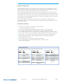
vicorpower.com PE AC PE +5 V +12 V Smart Fan controller FAN EMI Filter DC 85 – 264 Vrms 47 – 400 Hz 120 – 300 Vdc External 15 A fuse required MicroPAC Chassis PIC program Port T Temp detecon on Boost heatsink Bridge Recfier PE Microcontroller PFC Control +12 V Boost Converters 20 MHz +5 V +12 V BCM control So Start +5 V +12 V House Keeping BCM_1 BCM_1 BCM_1 BCM_1 Applications Engineering: 800 927.9474 Over Temp Fan Fault AC_OK Standby Mode GSD ED/4 ED/3 ED/2 ED/1 Reverse logic 1) +5.0 Vdc 2) OV 3) ED 1 4) Over Temp Warning 5) ED 3 6) AC_OK 7) Standby Mode 8) General Shutdown 9) Fan Fault 10) ED 2 11) N/C 12) ED 4 Interface Connector LED Indicators Isolated +5 Vdc / 500 mA Isolated Output Isolated Output Isolated Output Isolated Output Brief Technical Description The MicroPAC power supply is designed to operate using a single phase voltage source input between 85 Vrms and 264 Vrms or 120 to 300 V dc source. The basic building blocks of the MicroPAC are an EMI filter, Power Factor Correction stage, cooling fan, and housekeeping, associated microcontroller circuits along with customer interfaces and galvanic isolated outputs and control signals. Figure 1: Simple Block Diagram Page 3