1
AT&T
AT&T SYSTEM 25
CALL MANAGEMENT SYSTEM
SYSTEM MANUAL
©1988 AT&T
All Rights Reserved
Printed in USA
Call Management System
System Manual
Prepared by System 25
Document Development Group and the
Technical Publications Group
Contents
Section 1: Introduction
How to Use the CMS Documents
1-1
Section 2: Understanding CMS
Overview
Key Terms and Concepts
Optional CMS Features
A Typical CMS Application
Managing CMS
CMS Components
2-1
2-2
2-5
2-10
2-13
2-15
Section 3: Your PC and CMS
Overview
Duplicating the CMS Diskettes
Installing the CMS Software
Using Your PC with CMS
3-1
3-2
3-5
3-10
Section 4: Administering CMS
Overview
Getting Started
Administering Stations
Administering CMS Lines and Line Groups
Creating an Agent Directory
Building or Editing Shift Configurations
Setting Options
Selecting Exceptions
Printing System 25 Administration Instructions
Backing Up Shift Configurations
4-1
4-4
4-6
4-10
4-26
4-29
4-47
4-51
4-63
4-67
Section 5: Supervising CMS
Overview
Startup Procedures
Making Agents Available for CMS Calls
Monitoring Call Management
Supervising Your Agents
Dynamic Reconfiguration
Selecting Day or Night Service
Day-to-Day Operation of CMS
5-1
5-3
5-8
5-10
5-33
5-34
5-49
5-53
Section 6: Handling CMS Calls
Overview
The Agent’s Voice Terminal
The CMS Supervisor’s Voice Terminal
6-1
6-2
6-10
Section 7: Generating CMS Reports
Overview
Types of CMS Reports
7-1
7-3
Section 8: Archiving Data
Overview
8-1
Section 9: Troubleshooting
Overview
Startup Problems
Call Management Problems
Voice Announcement Unit Problems
Printer Problems
Agent Problems
System Errors
Running CMS from a Floppy Diskette Backup
Managing Calls When CMS is Not Running
9-1
9-2
9-18
9-22
9-26
9-29
9-33
9-34
9-35
Section 10: Ongoing System 25 Administration
Overview
The Partial Print
Adding Lines, Stations, or Voice Announcement Units
Changing Station, Line, PC Jack, or VAU Information
Removing Lines, Stations or Voice Announcement Units
10-1
10-2
10-5
10-7
10-8
Glossary
Overview
CMS and System 25 Terms
G-1
G-2
Index
Index
I-l
Section 1: Introduction
How to Use the CMS Documents
The Call Management System (CMS) is the Automatic Call Distributor (ACD)
for System 25. The CMS component of System 25 answers calls and connects
them to available agents. When there’s more than one agent available for a
call, CMS connects the call to the agent who has been idle the longest. If no
agent is available, CMS connects the call to a delay message. When the
message is finished playing, CMS places the call on hold until an agent
becomes available.
It’s important that your System 25 is administered to support CMS and that
the CMS options and parameters are set to meet your call management
needs. The explanations and instructions in each of the following CMS
documents can contribute to a fully integrated System 25/CMS system.
CMS PLANNING GUIDE
(555-532-650)
The AT&T System 25 Call Management System Planning Guide (CMS Planning
Guide) is designed to help you, the CMS Supervisor, together with the System
25 Administrator plan a fully integrated System 25/CMS oriented to the way
your business operates. The “Original Forms” section of the AT&T System 25
Call Management System binder (CMS binder) includes planning forms for
recording the decisions you make during planning. A complete set of
planning forms will help ensure a trouble-free system installation and
administration.
NOTE: If you don’t have a completed set of planning forms at this
point, the CMS Planning Guide is the place to start.
CMS INSTALLATION AND
STARTUP GUIDE
(555-532-504)
The AT&T System 25 Call Management System Installation and Startup Guide
(CMS Installation and Startup Guide) comes packaged with the CMS binder.
When you have completed the planning forms described in the CMS Planning
Guide, the System 25/CMS installer can use the CMS Installation and Startup
Guide to get your CMS up and running. This document leads the System
25/CMS installer through the steps needed to prepare the PC for CMS. These
include:
•
Installing the AT&T CMS PC Interface Card
•
Installing the MS-DOS operating system
•
Installing the CMS software
•
Administering CMS
•
Administering System 25 to support CMS
•
Testing CMS
When finished, you will have a fully operational CMS with a primary
configuration.
Once you have an operational shift configuration, you should keep the CMS
Installation and Startup Guide in the CMS binder for future reference.
How to Use the CMS Documents 1-1
CMS SYSTEM MANUAL
(555-532-110)
This is the manual you are reading now. It contains information on every
aspect of CMS operation and administration, from understanding CMS to
troubleshooting. The AT&T System 25 Call Management System, System Manual
(CMS System Manual) can be used after the initial installation and
administration described in the CMS Installation and Startup Guide.
AGENT CARD
(555-532-506)
Copies of the card are packaged with this binder. CMS agents can use the
card as a handy reference for using the agent voice terminal with CMS. Each
CMS Supervisor and agent should have one of these cards.
What’s in This Manual
The CMS System Manual is intended for the CMS Supervisor, the person
who oversees the setup and operation of CMS, and the System 25
Administrator, who is responsible for the administration and operation of
System 25. Here you will find an overall description of CMS – all the
concepts, procedures, and other information you need to make the most of
CMS in your business. This information is organized as follows:
Introduction
This section previews the contents of the manual and explains what the
special symbols and typefaces mean.
Understanding CMS
This section includes the following background information about CMS:
— Definitions and descriptions of key terms and features
– Description of how Bon Voyage Travel, a fictitious business, uses CMS
– Description of the responsibilities and interactions of the CMS Supervisor
and the System 25 Administrator for CMS operation
– Description of CMS components
– Contingency planning
Your PC and CMS
This section gives you instructions on how to make duplicates of the CMS
diskettes and install the CMS software. You’ll also learn how to enter and
edit data in response to prompts that appear on your AT&T Personal
Computer (PC) screen.
1-2 How to Use the CMS Documents
Administering CMS
This section tells you how to use your PC to administer CMS. This includes
identifying stations, identifying agents, identifying CMS lines, assigning voice
announcement units, and building a shift configuration (an arrangement of
line groups and agent splits for call management).
This section also describes other administration tasks used to fine tune CMS
for your business. These include setting options and exception thresholds to
alert you of unusual and undesirable situations. Procedures for making a
backup copy of your shift configuration(s) are also described. A menu map
illustrates the interrelationships of the screens used for CMS administration.
Supervising CMS
From the information in this section, you will learn how to activate a shift
configuration, monitor system status, and dynamically reconfigure the
system. Dynamic reconfiguration involves changing the configuration that is
currently being used to manage calls, for example, moving an agent from one
split to another. Menu maps show you the screens you will be using. This
section also describes two modes of CMS operation: Day Service and Night
Service.
Handling CMS Calls
This section includes criteria for selecting the right voice terminal for your
agents and for the supervisor station. It also includes procedures for using
voice terminal features for CMS.
Generating Reports
This sections describes the types of reports available from CMS, and how to
select, print, and interpret these reports.
Archiving Data
The information in this section tells you how to archive historical data onto
floppy diskettes for storage and analysis.
Troubleshooting
This section helps you identify system problems and correct them.
Glossary
The Glossary defines CMS and System 25 terms.
Index
The index provides page references for screens, terms, and procedures.
How to Use the CMS Documents 1-3
Documentation Conventions
Several special symbols and typefaces appear in this manual.
For instance, keys that appear on your keyboard are shown like this:
[F1] (fuction key F1) and
[Shift] + [Print Scrn] (press the [Print Scrn] key while holding down the [Shift]
key to print a screen).
The following typefaces are used to distinguish information you type (using
the keyboard) from information that appears on your PC screen:
This italic bold typeface represents information that you type on the PC screen.
This bold typeface represents information that CMS or MS-DOS displays, such as a
prompt or message.
1-4 How to Use the CMS Documents
Section 2: Understanding CMS
Overview
The Call Management System for System 25 is a powerful tool for managing
your incoming calls. With CMS, you can handle calls efficiently, distribute
the workload equally among your agents, and collect many types of data on
call traffic and call handling performance.
“Understanding CMS” includes information that is basic to understanding
CMS. It is organized as follows:
Key Terms and Concepts
Explains important CMS terms.
Optional CMS Features
Describes four optional CMS features.
A Typical CMS Application
Describes how Bon Voyage Travel, a fictitious business, uses CMS to manage
its incoming call traffic. This example appears throughout this manual and
other CMS documents to illustrate CMS concepts.
Managing CMS
Lists the responsibilities and interactions of the CMS Supervisor and the
System 25 Administrator for CMS operation.
CMS Components
Describes hardware, software, and trunks that are required or can be used
with CMS. Also included are procedures for recording messages on the voice
announcement units.
Overview 2-1
Key Terms and Concepts
The terms listed below appear frequently in this manual and other CMS
documents. The paragraphs that follow the list offer explanations of these
key concepts:
• Automatic Call Distributor
(ACD)
• Trunks (Lines)
• Line groups
• Line sub-groups
• Priority lines
• Agents
• Agent splits
• Shift configurations
• Main and secondary splits
• Intraflow
• Intraflow Threshold
• Answer Delay
• Force Delay
• Logged Out state
• Available state
• After-Call-Work (ACW) state
• Call management
• Day Service
• Night Service
CMS is the Automatic Call Distributor (ACD) designed to work with your
System 25 communications system. It distributes calls that come in on the
System 25 trunks that have been assigned to CMS. (Although CMS
personnel may know these as lines, the System 25 Administrator will refer to
them as trunks.)
NOTE: A System 25 may have more than one CMS, but each CMS
requires its own PC, hardware, and software.
The System 25 telephone lines assigned to CMS are organized into line
groups. You usually assign lines to line groups so that all calls coming in on
lines assigned to a particular line group are the same type. For instance, the
lines for a service department might be assigned to one line group; the lines
for a billing inquiries department might be assigned to a second line group,
and the lines for a sales department might be assigned to a third line group.
You can assign up to 28 telephone lines to CMS, and you can divide the lines
among a maximum of four line groups. In order to have CMS generate
reports on separate lines or smaller groups of lines within a line group, you
can also divide the lines in your line groups into sub-groups. Each line group
can have its lines divided into a maximum of seven line sub-groups. If you
have lines that should be answered before other lines in a line group, you can
designate these lines as priority lines.
Incoming calls are answered by agents who are organized into agent splits.
A split is a team of agents who handle the same type of call. Each split is
assigned to answer calls for one or more line groups. You can have up to six
splits handling CMS calls at the same time, and you can assign up to 28
agents to a split. A maximum of 28 agents can be active in CMS at any one
time.
A shift configuration is an arrangement of agent splits for answering calls.
You can store up to six shift configurations in the system’s memory, but only
one shift configuration can be active at a time.
2-2 Key Terms and Concepts
In a shift configuration, some agent splits are main splits and others are
secondary splits. A main split has primary responsibility for answering calls
for a line group. A secondary split acts as a backup to the main split for a
line group. Agents in the secondary split answer calls that come in for the
line group when all agents in the main split are busy or unavailable. Routing
calls to the secondary split is called intraflow. The number of seconds a call
waits for an agent in the main split before it is eligible to be sent to the
secondary split is called the Intraflow Threshold.
The Answer Delay is the number of seconds CMS lets a call ring before
answering it and connecting it to the voice announcement unit if no agent is
available to service the call. When you turn on the Force Delay option, no
calls arriving for a group are transferred to an agent until callers have heard
the entire delay message, even if an agent is available. If Force Delay is off,
calls are transferred to an agent as soon as one becomes available.
When call management begins for a shift, the agents in the shift are in the
Logged Out state. CMS neither sends calls to nor keeps statistics on agents
who are logged out. The agents must signal CMS when they are ready to
receive calls, that is, they must put themselves in the Available state. Agents
enter the Available state by turning on the light next to the Available button
on their voice terminals. CMS will send calls to agents who have indicated to
CMS that they are available. When agents need time to complete work on
their most recent CMS call (such as processing an order or updating a record),
they can leave the Available state and enter the After-Call-Work (ACW) state
by pressing the ACW button to turn on the light next to it. (The light next to
the Available button is automatically extinguished.) CMS does not send calls
to agents who are in the ACW state. When agents are neither handling calls
nor doing after-call-work, they log themselves out by pressing their Logged
Out button, which turns on the light next to it.
CMS automatically changes the agent’s state under the following conditions:
•
When an agent is moved or added to an active shift configuration, the
agent is put in the Logged Out state.
•
If an agent does not answer a CMS call within the number of rings
specified as the Transfer Return Threshold, the agent is put in the ACW
state.
•
If you have the Agent Logout ACW exception turned on, an agent who
has been in the ACW state longer than the specified time is placed in the
Logged Out state.
•
When you put CMS in Night Service mode, agents’ voice terminals are
placed in the Logged Out state.
From the CMS PC, you can move an agent from the Logged Out state to the
Available state, or you can log out an agent who is in the Available or ACW
state.
Key Terms and Concepts 2-3
Call management is the automatic distribution of calls that come in on CMS
lines. CMS provides two modes of call management, Day Service and Night
Service. When Day Service mode is active, a call that comes into CMS goes
through this basic sequence of steps:
1 . CMS looks for an available agent in the main split assigned to the line
group on which the call came in. (If the Force Delay option is turned on,
calls are not transferred to an agent until callers have heard the entire
delay message, even if an agent is available.)
2 . If agents in the main split are available, CMS routes the call to the agent
who has been idle the longest.
If no agent is available, CMS connects the call to a voice announcement
unit for a delay message after waiting the number of seconds specified as
the Answer Delay. If an agent becomes available while the delay message
is playing, CMS immediately transfers the call to the agent and the caller
does not hear the complete delay message.
3 . If no agent has become available by the end of the delay message, CMS
puts the call on hold in the main split’s queue of waiting calls.
4 . As soon as an agent in the main split becomes available, CMS transfers
the call at the front of the queue to the agent.
5 . If no agent in the main split becomes available and the call at the front of
the queue has waited a predetermined amount of time (the Intraflow
Threshold), the call is sent to an available agent in the secondary split (if
intraflow has been turned on for the split and a secondary split has been
administered for the call’s line group).
When CMS Night Service is active, CMS routes calls to a voice announcement
unit, and disconnects the calls after the message is finished.
2-4 Key Terms and Concepts
Optional CMS Features
As you plan your CMS, you may want to consider the following optional
features for CMS operation:
THE ASSIST FEATURE
•
The Assist and Transfer-into-Queue features help CMS agents in their
daily routine.
•
•
The Service Monitoring feature allows you to monitor your agents’ calls.
When CMS is not managing calls, you can use the CMS contingency plan
to distribute calls automatically to agents.
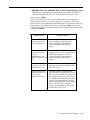
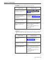
Feature Description
The Assist feature provides agents with a visual means of signaling you when
they need assistance. The System 25 Station-to-Station Message Waiting
feature is used to implement this feature.
When help is needed, an agent presses the Assist (MSG WAIT) button on the
agent voice terminal. This turns on the light next to the agent’s Assist button
and also turns on the light next to the paired Assist (MSG WAIT) button on
the supervisor voice terminal. A subsequent press of the Assist button from
either voice terminal turns off both lights. If the agent has a call in progress,
using the Assist button will not disrupt the call.
Button Requirements
This feature requires an administered System 25 MSG WAIT button on the
agent’s voice terminal and a paired MSG WAIT button on your supervisor
voice terminal. The supervisor voice terminal must have a paired MSG WAIT
button for each agent who has this feature.
Hardware Requirements
None.
CMS Administration Requirements
None.
System 25 Administration Requirements
A MSG WAIT button must be administered on both the agent and supervisor
voice terminal.
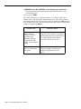
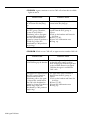
THE
TRANSFER-INTO-QUEUE
FEATURE
Feature Description
The Transfer-into-Queue feature is designed to facilitate the handling of calls
that come in on a trunk associated with one line group when the caller
actually needs to speak to an agent handling calls for another line group.
For example, a retail business has set up its CMS with three line groups:
Sales, Service, and Billing. Each line group is serviced by a split of the same
name. A caller with a question about an invoice mistakenly calls in on a line
in the Sales line group. The agent in the Sales split who answers the call
uses this feature to transfer the call to a transfer-queue line in the Billing line
group. Transfer-queue lines are priority lines. CMS, therefore, places this
call at the front of the Billing line group’s queue of waiting calls so that it will
be answered by the first available agent in the Billing split.
Optional CMS Features 2-5
The CMS Transfer-into-Queue feature can be used by CMS agents and other
System 25 users; for example, the System 25 Attendant can use this feature to
transfer calls that come in on non-CMS lines to a particular CMS line group
for servicing. The agent, or other System 25 user, transfers the call to a
“ghost” single-line voice terminal whose associated System 25 port on a Tip
Ring Line or Analog Line Circuit Pack is physically connected to a port on a
Loop Start Trunk Circuit Pack. Though neither a “real” single-line voice
terminal nor a loop start trunk is used with this feature, one real single-line
(Tip Ring Line or Analog Line) port and one real Loop Start Trunk port are
required for each transfer-queue line. See “Hardware Requirements” for this
feature below. A line group can have up to three transfer-queue lines
assigned to it.
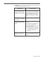
If a CMS agent answers the original call, both the agent who transfers the call
and the agent who services the transferred call get credit for handling a CMS
call on CMS reports. CMS statistics count the call as two distinct CMS calls.
Button Requirements
Though no voice terminal buttons are required for this feature, you may want
to have a DSS, Flex DSS, or Repertory Dial button on your agents’ voice
terminals programmed with the PDC of the “ghost” single-line voice terminal
associated with the transfer-queue line. This will provide one-touch dialing of
that voice terminal’s PDC.
Even if there is more than one transfer-queue line assigned to the line group,
only one button is required. It can be programmed with the PDC of any one
of the single-line voice terminals associated with that group of transfer-queue
lines. If the “ghost” single-line voice terminal dialed is busy, the call
automatically hunts to the next “ghost” single-line voice terminal in the
group.
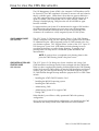
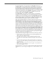
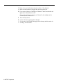
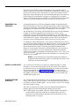
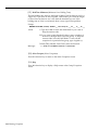
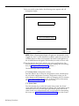
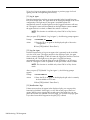
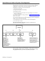
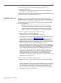
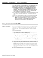
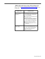
Hardware Requirements
For each transfer-queue line, a port on a Tip Ring Line (ZTN78) or Analog
Line (TN742) Circuit Pack, and a port on a Loop Start Trunk (ZTN77) Circuit
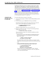
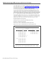
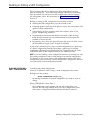
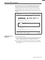
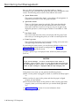
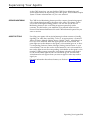
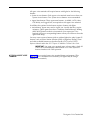
Pack are required. Figure 2-1 illustrates the hardware connection for this
CMS feature.
2-6 Optional CMS Features
FIGURE 2-1 Hardware Connections for the Transfer-into-Queue Feature.
LEGEND:
ZTN77 - C.O. Line Loop Start Trunk Circuit Pack
B - 3 to 1 Splitter Connectorized Cable (OR6016)
ZTN78 - Tip Ring Line Circuit Pack
W1 - 1-Pair Inside Wiring Cable
TN742 - Analog Line Circuit Pack
C2 - Octopus Cable (WP90780)
CMS Administration Requirements
The transfer-queue line must be administered on the Admin Queued Transfer
screen. See “Administering Transfer-Queue Lines” in Section 4 for details.
System 25 Administration Requirements
The "ghost” single-line voice terminal port and Loop Start Trunk port must be
administered according to the instructions on computer-generated System
25/CMS Single-Line Voice Terminal and Central Office Trunks
implementation forms.
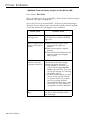
SERVICE MONITORING
Feature Description
The CMS Service Monitoring feature provides a means for you to monitor
(that is, listen in on) agents’ calls without being detected by the agent or the
caller. This feature can be very useful in the training process. You can also
use this feature to join a CMS call when an agent requests help with a caller.
Only CMS calls can be monitored with this feature.
Button Requirements
Your supervisor voice terminal needs an administered Personal Line button
with lights for each CMS and transfer-queue line you may want to monitor.
Optional CMS Features 2-7
Hardware Requirement
None.
CMS Administration Requirements
None.
System 25 Administration Requirements
Administer Personal Line buttons on your supervisor voice terminal.
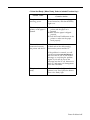
CONTINGENCY PLAN
Feature Description
When CMS is not managing calls, either because you are generating reports
or administering the system, or in the event of PC problems which prevent
CMS from managing calls, you can still distribute calls automatically to agents
if you have implemented the CMS contingency plan. This backup plan uses
the System 25 Direct Group Calling (DGC) Group Coverage feature to
distribute CMS calls to predefined groups of agents. Each of these agent
groups is known as a System 25 DGC group. Calls to a DGC group hunt for
an idle voice terminal in a circular manner starting with the voice terminal
following the last one to ring (whether or not the call was answered at that
voice terminal). CMS statistics are not kept for calls handled through the
DGC feature. For information on using this feature to manage calls, see
"Managing Calls When CMS is Not Running" in Section 9.
Button Requirements
None.
Hardware Requirements
None.
CMS Administration Requirements
None.
System 25 Administration Requirements
For each CMS line group, a "ghost" 34-button voice terminal on a fictitious
System 25 ATL Line Circuit Pack must be administered. Each "ghost" voice
terminal must have a Personal Line button administered for each CMS and
transfer-queue line in that line group. The "ghost" voice terminal must also
have DGC Group Coverage. The DGC group covering the "ghost" voice
terminal must be administered to include the agent voice terminals which
normally handle calls to the line group.
In the section, "Completing System 25/CMS Implementation Forms", in the
CMS Planning Guide, you will find information for setting up this contingency
plan. It is strongly recommended that you complete the necessary System
25/CMS implementation forms for the contingency plan and that you have
your System 25 Administrator or System 25/CMS installer complete all
necessary administration before you start using CMS so this alternate means of
call distribution is available if you should need to use it.
2-8 Optional CMS Features
IMPORTANT: The administration of fictitious System 25 voice terminal
ports causes the following message to be entered as a Permanent
System Alarm and also causes the Alarm light on the Attendant
console to flash following a Warm Start of System 25:
XXXXX Port Board Missing But Administered
(XXXXX represents the port number of the fictitious port.)
The Attendant Alarm light can be turned off by removing the
Permanent System Alarm message through System 25 administration.
The System 25 translations for the fictitious port(s) must not be
removed or the CMS contingency plan, described above, will not
work.
Optional CMS Features 2-9
A Typical CMS Application
In this part of the manual you’ll learn about a fictitious travel agency, Bon
Voyage Travel, which uses CMS to manage the revenue producing incoming
call traffic for its System 25 communications system. Examples based on Bon
Voyage Travel are used in the remaining sections of this manual.
CMS AND BON VOYAGE
TRAVEL
At Bon Voyage Travel, agents plan and book trips for several types of
customers. Most of the travel agency orders are placed by phone, so CMS
plays an important role in the agency’s daily business transactions.
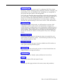
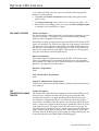
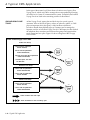
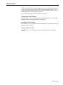
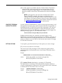
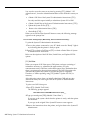
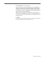
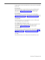
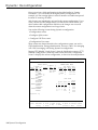
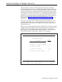
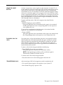
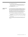
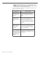
In order to handle three different types of customers and to manage the
frequent overflow of calls, Bon Voyage Travel’s CMS Supervisor has divided
the telephone lines customers use into three line groups and organized the
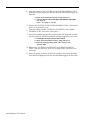
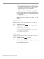
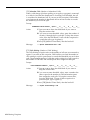
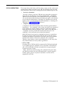
travel agents into four splits. Figure 2-2 shows a diagram of Bon Voyage
Travel’s CMS.
FIGURE 2-2 Bon Voyage Travel’s CMS.
Public Line Group
4 lines with the published
number 555-3070;
2 lines with the published
number 800-555-4185;
2 priority Lines with the unpublished
number 800-555-4950;
1 transfer-queue line with
the PDC 500.
Business Line Group
4 lines with the published
number 800-555-1242;
2 lines with the published
number 555-8300.
Charter Line Group
2 lines with the published
number 555-1234;
3 lines with the published
number 800-555-3000.
= Calls routed to the main split
= Calls intraflowed to the secondary split
2-10 A Typical CMS Application
• The Public line group has nine lines, eight Central Office (CO) trunks and
one transfer-queue line. There are four local lines with the published
number 555-3070, and two WATS lines with the published number 800555-4185. The number for the local lines is published in the Yellow Pages
and advertised in the local newspapers; the number for the WATS lines is
advertised in several national travel magazines. There are also two
priority lines with the number 800-555-4950. These lines are reserved for
valued repeat customers who may book several trips with Bon Voyage
Travel each year. Their unpublished telephone number is given only to
these preferred clients. For reporting purposes, the Central Office lines
have been divided into three line sub-groups, Public local lines (PL),
Public WATS lines (PW), and Public special lines (PS).
In addition, there is one transfer-queue line assigned to this line group.
When calls come in on lines other than the Public line group’s lines and
need to be placed in the Public line group’s queue of waiting calls, agents
can transfer the calls to PDC 500, the PDC of the single-line port
associated with the transfer-queue line. The transfer-queue line is in line
sub-group Q1.
Calls coming into the Public -line group are from customers who want to
book personal vacations. The Public Travel split handles calls that come
into the Public line group.
To provide optimal service to customers when there is a high volume of
call traffic coming into the Public line group, the Support split has been
assigned as the Public line group’s secondary (or backup) split. The
number of agents available for CMS calls in this split varies according to
the incoming call traffic. The employees who staff the Support split have
primary responsibilities such as bookkeeping, advertising, and trip
packaging. But, since these people have some experience as travel agents,
they are often used to back up the Personal Travel split when call traffic is
heavy on the lines in the Public line group.
• The Business line group consists of six lines. These lines have been
divided into two line sub-groups. One line sub-group, BW, contains four
WATS lines with the published number 800-555-1242. The other line subgroup, BL, has two lines for local service with the advertised number 5558300.
Calls coming into this line group are from large corporations wishing to
book business trips for their employees. The Business Travel split serves
as this line group’s main split.
• The Charter line group consists of five lines, divided into two line subgroups. Two lines, which have the published number 555-1234 listed in
the local Yellow Pages, are in the line sub-group CL. Three WATS lines,
which have the published number 800-555-3000 listed in national travel
magazines, are in the line sub-group CW.
The Charter Travel split, which handles CMS calls coming into the
Charter line group, arranges trips for groups and frequently books trips
for local and national holiday clubs.
A Typical CMS Application
2-11
Occasionally, customers who have previously made travel arrangements
through a holiday club will call one of the Charter line group’s numbers to
make personal travel arrangements. In these cases the agent in the
Charter split who receives the call uses the Transfer-into-Queue feature to
transfer the call to the Public line group’s queue of waiting calls. CMS
then distributes the call to an agent in the Public Travel split.
Since both the Charter Travel split and the Business Travel split handle
group trips, the Business Travel split serves as a secondary split to handle
call overflow from the Charter Travel split. Likewise, the Charter Travel
split backs up the Business Travel split during peak calling hours.
BON VOYAGE TRAVEL’S
OTHER CALL TRAFFIC
All of Bon Voyage Travel’s voice terminals and outside telephone lines are
part of the agency’s System 25 communications system, but some of Bon
Voyage Travel’s voice terminals and outside lines are not assigned to the Call
Management System. Agents and nonagents alike use lines not assigned to
CMS for all outgoing calls and nonrevenue producing incoming calls.
CMS AND OTHER
BUSINESSES
Bon Voyage Travel’s line groups and agent splits are typical for a travel
agency. Other types of businesses would have other names for their line
groups and splits. For example, a wholesale distributor might have line
groups and splits for inside sales and customer service (such as order
tracking) while a bank may have line groups and splits dedicated to specific
types of loans and customer services. The characteristics of your business
should dictate your decisions as you plan your CMS.
2-12 A Typical CMS Application
Managing CMS
Since System 25 must be administered to support CMS, the CMS Supervisor
and the System 25 Administrator work together to ensure successful CMS
operation. This section describes the typical CMS interactions and
responsibilities of these two people.
RESPONSIBILITIES OF
THE CMS SUPERVISOR
The CMS Supervisor has many responsibilities, all of which are described in
this manual. Typically, the role of the CMS Supervisor involves:
• Working with the System 25 Administrator to:
– Identify and record port numbers, PDCs, and trunk numbers for CMS
equipment
– Ensure removal of stations or trunks no longer needed by CMS
– See that System 25 administration needed to support CMS is
performed
Administering CMS, including the following:
Administering stations, CMS lines, transfer-queue lines, line groups,
and voice announcement units
– Building an Agent Directory
– Creating shift configurations of line groups and agent splits
– Setting options
– Selecting Exception Thresholds to be monitored
– Printing System 25 administration instructions
See Section 4, “Administering CMS. ”
• Monitoring line status, split status, call traffic, and system problems
during call management, and making changes to shift configurations as
needed, to ensure efficient call handling and maximum agent productivity.
See “Monitoring Call Management” and “Dynamic Reconfiguration” in
Section 5.
• Helping agents understand how to use their voice terminals for handling
CMS calls. See Section 6, “Handling CMS Calls. ”
• Generating reports and using the data in the CMS reports to maintain
efficient call management and agent productivity. See Section 7,
"Generating Reports," for ongoing data collection; see Section 8,
"Archiving Data," for storing historical CMS data.
• Having a contingency plan in place and using it to manage calls when
CMS is not running. See “Managing Calls When CMS is Not Running” in
Section 9.
• Troubleshooting. See Section 9, “Troubleshooting.”
Managing CMS
2-13
RESPONSIBILITIES OF
THE SYSTEM 25
ADMINISTRATOR
2-14 Managing CMS
System 25 and CMS must be administered identically with respect to trunk
numbers, port numbers, PDCs, and feature button assignments required by
CMS. The following are typical responsibilities involved in maintaining
harmony between the two systems:
●
Assigning trunk numbers, ports, and PDCs to CMS equipment and
facilities, both when CMS is installed and when more resources are
needed.
●
Using the System 25 administration instructions printed out by the CMS
software, along with hand-completed System 25/CMS implementation
forms, to administer System 25 for CMS.
●
Backing up System 25 translations to a tape or diskette when CMS is first
configured and after changes are made. (Translations are specific
information assigned to a voice terminal or System 25 such as port
numbers and PDCs. )
CMS Components
This section lists the hardware required for and trunks compatible with CMS.
HARDWARE COMPATABLE
WITH CMS
•
•
•
The following hardware and software are required for CMS:
AT&T System 25: Release 2
An AT&T Personal Computer (PC), with the following characteristics:
— Hard disk (10 MB and 512K RAM minimum)
— One floppy diskette drive
— MS-DOS 3.2, Version 2.02 (or higher)
•
•
•
•
•
—
Keyboard
—
Monochrome or color monitor
AT&T Printer Model 473 (or compatible parallel printer)
AT&T CMS PC Interface Card
Two System 25-CMS floppy diskettes
At least two blank floppy diskettes
Agent voice terminals (any of the following):
— 5-Button Voice Terminal
— 10-Button Voice Terminal
— 10-Button Hands-Free Answer on Intercom (HFAI) Voice Terminal
— 10-Button Built-in Speakerphone (BIS) Voice Terminal
— 22-Button BIS Voice Terminal
34-Button Voice Terminal
— 34-Button Deluxe Voice Terminal
— 34-Button BIS Voice Terminal
34-Button Deluxe BIS Voice Terminal
— 34-Button BIS Voice Terminal with Display
— 34-Button Deluxe BIS Voice Terminal with Display
— Direct Trunk Attendant Console (DTAC), a 34-Button Deluxe or
34-Button Deluxe BIS Voice Terminal
— Switched Loop Attendant Console (SLAC), a 34-Button Deluxe BIS
with Display -
•
Supervisor voice terminal:
– One 34-button Deluxe voice terminal is required. A second multiline
voice terminal may be needed.
•
For more information about selecting a voice terminal for yourself and for
the CMS agents, see Section 6, “Handling CMS Calls. ”
•
Cables:
– Two 14-foot 4-pair modular-plug stations cords (D8W-87) for
connections to the AT&T CMS PC Interface Card
CMS Components 2-15
The following optional hardware can be used with CMS:
● Up
to four Model DACON-DA-5SL voice announcement units (strongly
recommended). One 14-foot 2-pair modular-plug station cord (D4BU-87) is
required for each voice announcement unit.
● Headsets
and headset adapters
NOTE: A headset and headset adapter cannot be used with a 5-button
voice terminal or a 10-button HFAI voice terminal.
●A
music source compatible with the System 25 Music-on-Hold port
(strongly recommended).
●A
telephone answering machine capable of answering calls on the first
ring for special Night Service applications. See "Caller Message Recording
During Night Service" in Section 5.
TRUNKS COMPATIBLE
WITH CMS
Either Ground Start or Loop Start trunks maybe used with CMS, but
Ground Start trunks are strongly recommended because they lessen the
likelihood of abandoned calls being transferred to agents. Ground Start
trunks are also recommended if headsets will be used with voice terminals
used for CMS.
Central Office (CO), WATS (800 Service), and Foreign Exchange (FX) trunks
may be used with CMS. Trunks may be arranged in CO hunt groups. A
hunt group is a group of trunks that share a listed telephone number. When
a call comes in on the listed number, the CO switch scans the hunt group for
an idle trunk and connects the call to the first one it finds.
THE VOICE
ANNOUNCEMENT UNIT
Before recording delay messages on the DACON unit, read the
documentation that came with it, and keep the following guidelines in mind:
● You
can assign a separate voice announcement unit to each line
group, or two or more line groups can share one voice
announcement unit.
● The
voice announcement unit has two channels to provide two
messages, one for Day Service and the other for Night Service. The
announcement unit has 64 seconds of message time available that can
be divided between your two messages.
● Leave
3 or 4 seconds of silence before the beginning of your message
to allow time for CMS to connect the caller to the voice
announcement unit. This will ensure that the caller will hear the
message from the beginning.
● You
must note the length of the Day Service message on the Assign
Announcement screen. See “Assigning Announcements” in Section
4 for more information.
● If
call traffic is light when CMS is in Night Service mode, you can
use a telephone answering machine(s) to answer calls and record
callers’ voice messages. Refer to “Caller Message Recording During
Night Service” in Section 5 of this manual for additional information.
2-16 CMS Components
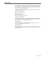
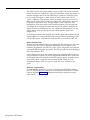
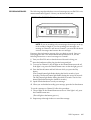
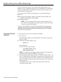
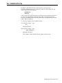
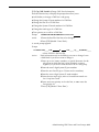
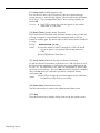
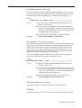
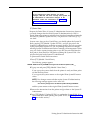
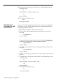
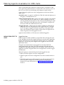
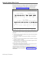
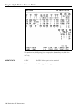
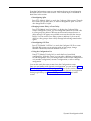
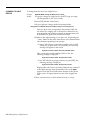
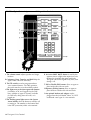
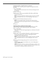
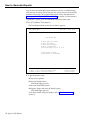
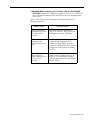
RECORDING MESSAGES
The following steps describe how to record a message on your DACON voice
announcement unit. Figure 2-3 shows you the front of the unit.
FIGURE 2-3 The DACON-DA-5SL Voice Announcement Unit.
NOTE: If you are recording only one message, the message can be up
to 64 seconds in length. If you are recording two messages, one
message on Channel 1 and one on Channel 2, you must divide the 64
seconds of message time between the two messages.
Prepare a clear, informative message before you begin to record. Once you
have plugged in the voice announcement unit and turned it on, use the
following instructions to record a message on Channel 1.
1 Turn your DACON unit so that the front of the unit is facing you.
2 Insert the handset modular plug into the front panel jack.
3 To record on Channel 1, the red light on the Channel button must be off.
If the light is on, press the Channel button once so that the light goes off.
4 Press the Record button and hold it down while you press the Play
button.
(The Channel button light flashes during the first 16 seconds of your
recording. The Record button light flashes during the second 16 seconds.
The Play button light flashes during the third 16 seconds. The On-Line
button light flashes during the fourth 16 seconds.)
5
Speak into the handset to record your message.
6
When you are finished recording your message, press the On-Line button.
To record a message on Channel 2, follow this procedure:
1
The red light on the Channel button must be on. If the light is off, press
the Channel button once.
(The red light on the button goes on.)
2
Repeat steps 4 through 6 above to record the message.
CMS Components
2-17
To listen to the recorded announcement on either of the channels:
1 Make sure the handset is plugged into the front panel jack.
2 If you want to listen to a message on Channel 1, make sure that the red
light on the Channel button is off.
If you want to listen to a message on Channel 2, the red light on the
Channel button should be on.
2-18 CMS Components
3
Press the Play button.
4
Listen to the message through the handset.
5
If you want to rerecord the message, follow the steps in this section for
recording announcements.
Section 3: Your PC and CMS
Overview
CMS runs on the AT&T Personal Computer (PC). By working with the CMS
menus and screens, you can tailor CMS to suit your business needs. This
section of the manual describes how to load the CMS software onto your PC’s
hard disk and how to enter data into your PC.
The information in this section is organized as follows:
Duplicating the CMS Diskettes
Describes how to make working copies of the CMS diskettes. (A set of blank
diskettes has been packaged with the CMS binder.)
Installing the CMS Software
Describes how to copy the CMS software onto the PC’s hard disk, and set the
time and date on your PC.
Using Your PC with CMS
Describes how to use CMS screens, enter and edit data, and access help
screens.
Overview 3-1
Duplicating the CMS Diskettes
Since it is important to protect your original CMS floppy diskettes from
damage or wear, a duplicate (working copy) of each diskette was made when
CMS was installed. Keep the originals in a safe place and use them only to
make additional working copies.
If you have to make additional working copies, you need the following:
●
Your PC
● The
original CMS diskettes, labeled “SYSTEM 25 CMS SYSTEM” and
“ SYSTEM 25 CMS REPORT AND ADMIN”
● Two
blank diskettes
NOTE: If you are reusing diskettes, make sure the diskettes do not
have old files on them that you need because they will be overwritten
when you copy the CMS diskettes.
In order to make duplicates of the CMS diskettes, MS-DOS (including the
“diskcopy” and “diskc omp” commands) must already be on the hard disk.
MS-DOS (including these commands) was installed on your PC’s hard disk
when CMS was first installed.
DUPLICATING THE CMS
DISKETTES
To make duplicate copies of the original CMS diskettes:
1 Turn on the PC.
If the CMS Menu appears, press [F8] (labled "Exit to DOS") to get to the
MS-DOS prompt.
2
When the C> prompt appears, type:
diskcopy a: a:
and press [Enter]
You see the following messages:
Insert SOURCE diskette in drive A:
Strike any key when ready . . .
NOTE: PC responses may be slightly different from the ones printed here,
depending on the version of MS-DOS you are using.
3
Insert the original CMS diskette labeled “SYSTEM 25 CMS SYSTEM, ” into
drive A with the label of the diskette facing upwards, and the notch in the
side of the diskette on the left. When you hear a click, indicating that the
diskette has been fully inserted, press down the latch on drive A until you
feel the latch lock.
This diskette is the “source” diskette, the diskette that contains the
information being copied.
3-2 Duplicating the CMS Diskettes
4
When you are ready, press any key.
The in-use light on disk drive A comes on while the system is reading the
source diskette.
WARNING
Do not remove a diskette from the drive while the
in-use light is on; data on the diskette may be
damaged or lost.
When the system has read the diskette, the following messages are
displayed:
Insert TARGET diskette in drive A:
Strike any key when ready. . .
5
When the in-use light on drive A is off, remove the source diskette, insert
a blank diskette, and press any key. This diskette is the “target” diskette,
the diskette on which the information is being copied.
The in-use light comes on while the system is copying the information
onto the target diskette. If the blank diskette is not formatted, the
message
Formatting While Copying
appears on the screen.
NOTE: Depending on the amount of memory on your PC, the system may
prompt you to swap diskettes during diskcopy.
When the copying process is finished, you see:
Copying complete
Copy another diskette (Y/N)?
6
Remove the duplicate diskette, write “SYSTEM 25 CMS SYSTEM
WORKING COPY” on a label using a felt tip pen, apply the label to the
diskette, and put the diskette in its paper sleeve. Return the original
diskette to its paper sleeve.
7
Type y. The following message appears:
Insert SOURCE diskette in drive A:
Strike any key when ready...
8
Insert the original CMS diskette labeled “SYSTEM 25 CMS REPORT AND
ADMIN” into drive A. This is the source diskette.
9
Repeat Steps 4 and 5, using the second blank diskette as the “target”
diskette.
Duplicating the CMS Diskettes 3-3
10
Type n when prompted to copy another diskette.
11
When the C> prompt appears, remove the duplicate diskette, write
“SYSTEM 25 CMS REPORT AND ADMIN WORKING COPY” on a label
using a felt tip pen, apply the label to the diskette, and store the diskette
in its paper sleeve. Return the original diskette to its paper sleeve.
12 Store both the original and working copy CMS diskettes in a safe place.
It is recommended that you store the working copy diskettes separately
from the original diskettes.
3-4 Duplicating the CMS Diskettes
Installing the CMS Software
Installing the CMS software involves copying the contents of the working
copies of the two CMS diskettes onto the PC’s hard disk. This was done
when CMS was first set up for you. As part of the installation procedure, a
CONFIG.SYS and an AUTOEXEC.BAT file were placed on your PC’s hard
disk. If these files existed prior to CMS installation, the installation procedure
edited these files. See “The CONFIG.SYS File” and “The AUTOEXEC.BAT
File” later in this section.
You can perform the following software procedures tore-install the CMS
software if errors occur that you cannot fix and you need to begin again.
When you are finished, the system will have copied the programs
required
— —
for CMS operations onto the ‘PC’s hard disk. COPYING THE CMS
SOFTWARE ONTO THE
PC’S HARD DISK
To copy the CMS software onto the PC’s hard disk:
1
Insert the diskette labeled “SYSTEM 25 CMS SYSTEM WORKING COPY”
into drive A.
2 At the C> prompt, type a:\cmsinstall and then press [Enter].
.
The following messages appear in the upper portion of the screen and
remain on the screen throughout the installation procedure:
**** SYSTEM 25 Call Management System
**** Installation Procedure
Additional messages appear in the lower area of the screen.
3 While the installation procedure is in progress, the following message
usually appears on your screen:
**** Installation Now In Progress. Please Wait...
However, there are a couple ways in which the installation procedure
could be interrupted:
— If there are errors on your CMS working copy diskette that prevent
the installation program from continuing, the following messages
appear on the screen:
**** ERROR on Installation Floppy Disk
Try installation from Another Floppy
Discard the diskette, make another working copy using the original
CMS diskette, and then begin the CMS software installation procedure
again.
— If there is insufficient storage space on the hard disk for new
information, the following messages appear on your screen:
**** “Insufficient Disk Space for CMS.
An Additional xxxK is Required.
Delete Old Files and Try Installation Again.
If you need directions on using the MS-DOS “delete” (del) and
“directory” (dir) commands to delete files, see the user’s guide that
came with the MS-DOS diskette.
Installing the CMS Software 3-5
4
After the contents of the “SYSTEM 25 CMS SYSTEM WORKING COPY”
diskette have been copied onto the hard disk, the following messages are
displayed:
**** Please remove the diskette currently in floppy disk drive A.
**** “Insert the diskette labeled SYSTEM 25 CMS REPORT AND ADMIN
into drive A.
Press ‘c’ to continue or ‘q’ to quit.
5
Remove the “SYSTEM 25 CMS SYSTEM WORKING COPY” diskette and
place it in its protective cover.
6
Insert the diskette labeled “SYSTEM 25 CMS REPORT AND ADMIN
WORKING COPY” into drive A and press c .
7
Once the installation program has copied all the CMS programs and files
onto the hard disk, the final installation messages appear on your screen:
**** Call Management System Successfully Installed.
**** Please remove the diskette currently in floppy disk drive A.
**** Reboot the system by holding down ‘CTRL’ and ‘ALT’ while
pressing ‘DEL.’
8
Remove the “SYSTEM 25 CMS REPORT AND ADMIN WORKING
COPY” from the disk drive, place it in its paper sleeve, and store it in a
safe place.
9
Reboot the system by holding down [Ctrl] and [Alt] while pressing [Delete].
After Resident Diagnostics are run, the CMS Menu appears
on the screen.
—
3-6 Installing the CMS Software
The CONFIG.SYS File
In order for the CMS software to run properly, you must have a
CONFIG.SYS file in the root (\) directory of the PC’s hard disk. This file
must contain the following lines:
BUFFERS =20
FILES =20
If the CONFIG.SYS file existed prior to CMS software installation, the above
two lines were appended to the file when CMS was installed. If no file
existed, a CONFIG.SYS file containing these lines was automatically created
when CMS was installed.
To view the contents of the CONFIG.SYS file:
1 At the C> prompt, type
cd \
then press [Enter]
2 At the C> prompt, type
type config.sys
then press [Enter].
The contents of the CONFIG.SYS file appear on the screen.
Installing the CMS Software 3-7
The AUTOEXEC.BAT File
During the CMS installation process, an AUTOEXEC.BAT file containing the
three lines below was placed on your PC’s hard disk. If the AUTOEXEC.BAT
file existed on your PC’s hard disk prior to CMS installation, these three lines
were added to the end of the file when CMS was installed.
The three lines are:
prompt $p$g
cd c: \cms
cms
The first line causes the full pathname of the current directory to be displayed
as part of the MS-DOS prompt. The second and third lines cause the CMS
Menu to displa}’ automatically after MS-DOS Resident Diagnostics are run.
This happens whenever your PC is turned on or MS-DOS is rebooted.
If you ever edit the AUTOEXEC.BAT file, make sure these lines remain as the
last three lines of the file.
To view the contents of the AUTOEXEC.BAT file:
1 At the C> prompt, type
cd \
then press [Enter].
2 At the C> prompt, type
type autoexec.bat
then press [Enter].
The contents of the AUTOEXEC.BAT file appear on the screen.
3-8 Installing the CMS Software
Setting the Time and Date
Since the date and time are significant parts of your daily CMS statistics, it is
important that your PC screen show the correct date and the correct time.
You can check the time and date by looking at the upper right-hand corner of
any CMS screen. If the time or date is incorrect, you can easily change it on
your PC.
To check or change the date on your PC:
1 Exit to MS-DOS by pressing [F8] (labeled “Exit to DOS”) on the CMS
Menu.
2 When the C> prompt appears, type
date
and press [Enter].
The following message appears on your screen:
Current date is Wed 4-07-1988
Enter new date (mm-dd-yy):
3 If the date is correct, press [Enter].
If the date is incorrect, type in the correct date in the form mm-dd-yy (for
example, 04-08-88 ) and press [Enter].
To check or change the time on your PC:
1 When the C> prompt appears, type
time
and press [Enter].
The following message appears on your screen:
Current time is 12:01:30.00
Enter new time:
2 If the time is correct, press [Enter].
If the time is incorrect, type in the correct hour and minute in the form
hh:mm (for example, 9:03) and press [Enter]. (MS-DOS works on the
basis of a 24-hour clock, so if you want to enter the time as 2:30 P.M. you
must type 14:30.)
MS-DOS keeps track of the seconds and hundredths of seconds.
You do not enter these details into your PC.
Installing the CMS Software 3-9
Using Your PC with CMS
This section describes the format of CMS screens, the method of entering and
editing data, and how to access help screens. If you have questions about
MS-DOS, the layout of your keyboard, or other information about your PC,
refer to the manuals that accompanied them.
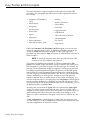
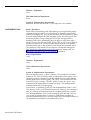
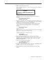
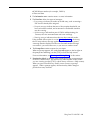
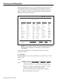
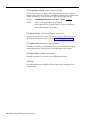
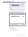
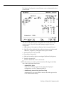
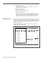
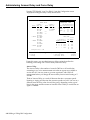
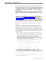
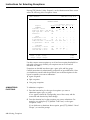
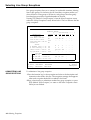
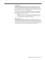
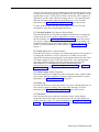
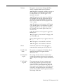
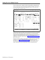
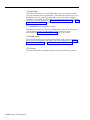
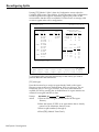
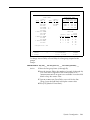
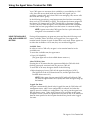
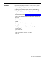
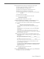
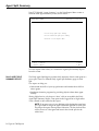
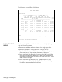
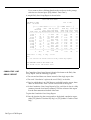
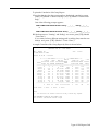
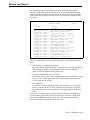
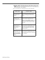
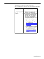
The general format of a CMS screen is demonstrated below in the Agent
Directory screen.
e
SCREEN FORMATS
c
a
1
AGENT DIRECTORY
ANNC CU1 CU2 Don’tPrtScr LoStorage
d
DAY CMS1.0 2:38p 04/18
AGENT DIRECTORY
Last Name
Abell
Beckman
Brown
Chu
Dumbra
Fang
Fenton
Garcia
Gerkensmeier
Johnson
Kesselring
Leonard
Lindquist
Lindquist
Mack
First
Mary-Ann
Jim
Allan
David
Marie
John
Scott
Jose
Otto
Andrew
Ana
Michael
Hal
Hal
Joel
ID
MARYA
JIM
ALLAN
DAVE
MARIE
John
SCOTT
JOSE
OTTO
ANDY
ANA
MIKE
HALl
HAL2
JOEL
Last Name
Marietta
Masson
Ong
Opalach
Reicheg
Rowlinson
Seiler
Siegel
Smith
Son
Stickler
Vatier
Walsh
Well
Yang
3
2:38 04/18 l *** Split 1 - Agent LINDA - Refused Calls
4
ADD AGENT: Last Name: Zuckerman
F Cancel
1 Prompt
5
First: Amy
ID: AMY
FPrevious F Next
5 Field 6 Field
First
Jane
William
Ien
Joseph
Louis
Don
Linda
Lawrence
Bernard
Sarah
Craig
Barbara
Jennifer
Harvey
CJ
ID
JANE
BILL
IEN
Joe
LOU
Don
LINDA
LARRY
BERNE
SARAH
CRAIG
BARB
JENNY
HARV
CJ
F Enter
8 Data
Each numbered or lettered term listed below corresponds to a number or
letter in the screen above. The following types of information may appear in
the indicated area of the screen.
1 The ID line contains:
a Screen name
b
c
Status indicators: ANNC blinks if there is a voice announcement unit
problem. (If you decide not to use any voice announcement units,
ANNC appears in the ID line, even though there is no problem.) If
there is a problem with the connections to the PC, CU1 and/or CU2
blinks. Don’tPrtSc appears if the printer is disconnected or is not
ready. NoStorage or LoStorage appears if there is a storage problem
on the hard disk. For information on resolving problems, see Section
9, “Troubleshooting.”
Current CMS mode: CMS appears when the CMS Menu is displayed.
DAY or NIGHT indicates that calls are being managed using Day
Service or Night Service mode, respectively. (See “Selecting Day or
Night Service” in Section 5.) ADMIN indicates CMS is being used for
administration. REPT appears when you generate reports.
3-10 Using Your PC with CMS
d CMS Release number (for example, CMS1.0)
e Time and date
2 The Information area contains menus or status information.
3 The Error line offers four types of messages:
— Error messages indicate you made an invalid entry, such as entering a
PDC that has already been assigned.
— Exception messages indicate that one of the exception thresholds you
have set has been reached, and an unusual or undesirable situation
may be occurring.
— System messages indicate that part of CMS is malfunctioning (for
instance, the voice announcement unit is not working).
— Warning messages indicate actions that may have unusual results.
If the Audible Alarm option is on (see “Setting Options” in Section 4),
the PC beeps when a message appears on the error line. In general,
a message remains displayed on the error line until another message
overwrites it, you correct the error, or you move to another screen.
4
The Prompt line contains requests for your input.
When no prompt appears, the words F10 - Help appear to the far right on
the prompt line reminding you that [F10] accesses the help screens.
For more information, see “Entering and Editing Data, ” in this section.
5
Function key labels in this area of the screen tell you the current meaning
of the PC’s function keys. The function key labels depend on the screen
you are viewing (except [F10], which always accesses a Help screen).
When you press a function key, usually a new screen or a prompt
appears. When a prompt appears, the function key labels change to
provide data entry functions.
Using Your PC with CMS 3-11
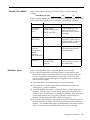
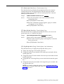
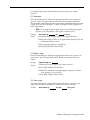
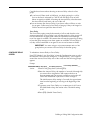
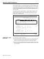
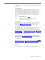
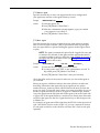
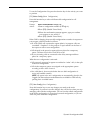
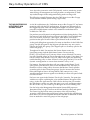
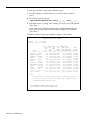
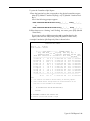
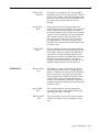
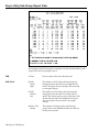
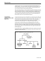
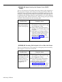
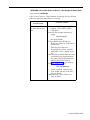
Entering and Editing Data
Entering and editing data is easy. You enter data by pressing function keys
and responding to the prompt that appears on the prompt line on your
screen. Prompts contain one or more fields (blank spaces) into which you
type your responses. Whenever a prompt appears, the function keys are
labeled as shown in the screen below.
AGENT DIRECTORY
ADMIN CMS1.O 2:31p 04/18
AGENT DIRECTORY
Last Name
Abell
Beckman
Brown
Chu
Dumbra
Fang
Fenton
Garcia
Gerkensmeir
Johnson
Kesselring
Leonard
Lindquist
Lindquist
Mack
ADD AGENT:
F Cancel
l Prompt
First
Mary-Ann
Jim
Allan
David
Marie
John
Scott
Jose
Otto
Andrew
Ana
Michael
Hal
Hal
Joel
Last Name:
ID
MARYA
JIM
ALLAN
DAVE
MARIE
JOHN
SCOTT
JOSE
OTTO
ANDY
ANA
MIKE
HAL1
HAL2
JOEL
Last Name
Manetta
Masson
Ong
Opalach
Reicheg
Rowlinson
Seiler
Seigel
Smith
Son
Stickler
Vatier
Walsh
Woll
Yang
First:
F Previous
5 Field
First
Jane
William
Ien
Joseph
Louis
Don
Linda
Lawrence
Bernard
Sarah
Craig
Barbara
Jennifer
Harvey
CJ
ID
JANE
BILL
IEN
JOE
LOU
DON
LINDA
LARRY
BERNE
SARAH
CRAIG
BARB
JENNY
HARV
CJ
ID:
F Next
8 Field
F Enter
8 Data
NOTE: When a prompt contains only one field, the only function keys
displayed are [F1] (labeled “Cancel Prompt”) and [F8] (labeled
“Enter Data” ).
In this manual, instructions for entering data in prompts are usually
presented as follows:
[F1] Add Agent
Pressing this function key on the Agent Directory screen allows you to add
agents to CMS.
Prompt:
ADD AGENT: Last Name:
Action:
First:
ID:
1 Enter a last name up to 12 letters, numbers, or special
characters (such as * or #), with no spaces between them.
2 Enter a first name up to eight letters, numbers, or special
characters, with no spaces between them.
3 Enter a unique ID up to five letters and/or numbers.
4 Press [F8] (labeled “Enter Data”).
3-12 Using Your PC with CMS
MOVING THE CURSOR
Many CMS prompts contain several empty fields, as in the following
example:
ADD AGENT: Last name:
First:
ID:
When a prompt appears, the cursor is positioned at the beginning of the first
field. Use the keys shown below to move the cursor within a prompt:
Press
Or
To move the cursor
[F5] (labeled
“Previous
Field”)
[Shift] + [Tab]
(while holding down
[Shift], press [Tab] )
to the beginning of the
previous field (except
when the cursor is in the
first field).
[F6] (labeled
“Next Field”)
[Tab]
to the beginning of the
next field. If the cursor is
in the last field, it will not
return to the first field.
[ → ] (the right
arrow key
located on the
numeric
keypad on
your keyboard)
[Backspace]
ENTERING DATA
one character to the right.
(This key does not work
in a blank field.)
[ ← ] (the left arrow key
on the numeric
keypad)
one character to the left.
(This key does not work
in a blank field.)
Follow these guidelines when completing the fields in a prompt:
●
You can type uppercase or lowercase letters in your entries. In this
manual, the sample entries are usually lowercase. On your screen, all
entries, except agent names, appear as uppercase, even if you typed
lowercase letters. Agent names appear in uppercase and/or lowercase
letters, exactly as typed.
●
Some field entries can contain numbers or special characters.
●
The system does not allow spaces between characters in a field; use
underscores (_) in these instances.
●
Press [F8] (labeled "Enter Data") or [Enter] when you finish typing your
response. This tells the PC to process the data you have entered. The
cursor can be in any field when you press [F8] or [Enter]. (The instructions
in this manual usually tell you to press [F8] after your last entry in a
prompt. You may press either [F8] or [Enter], however.)
●
If you skip a required field in a prompt and press [F8] or [Enter], your PC
beeps (provided the Audible Alarm option is On), and an error message
appears. The Audible Alarm option is administered from the Set Options
screen. If you have turned off this option, your PC does not beep.
Using Your PC with CMS 3-13
IMPORTANT: To cancel any prompt, press [F1] (labeled “Cancel
Prompt”) or [Delete]. Any data you entered in the prompt fields are
ignored, the prompt disappears, and the function key labels change
from data entry labels to the labels for the particular CMS screen.
EDITING DATA
To change a character in a field:
●
Move the cursor to the incorrect character and simply type another
character over it.
To add characters at the end of an entry:
●
Press [ → ] after the last character and type additional characters.
To insert characters in an entry:
●
Move the cursor to the first character you want to change and retype the
entry from that character onward. You cannot use [Insert] to insert a
character between other characters.
To replace a long entry with a shorter one:
●
VALIDATING DATA
Type over any characters you want to change, then press the space bar
after the last character of the new entry. The remaining characters in the
previous entry disappear. For example, to change “Joseph” to “Joe”,
move the cursor to “s”, type “e”, and press [Space]. The letters “eph”
disappear.
CMS validates the information entered in two ways:
1 The first type of validation occurs as you type each piece of information in
a field. If you make an invalid entry (for instance, entering a letter in a
numeric field), the PC beeps, the character does not display, and the
cursor remains in the same position so you can make another entry.
2 The second type of validation occurs after you press [F8] (labeled “Enter
Data n). At this point, CMS begins to validate each field of information
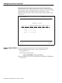
from left to right. If there is an invalid entry or you left a required field
blank, the PC beeps, and an error message appears above the prompt.
The cursor returns to the first error so you can correct the entry.
USING THE HELP
SCREENS
3-14 Using Your PC with CMS
You can press [F10] (labeled “Help”) on any screen to receive more
information about the function keys on that screen. To exit a Help screen and
return to your previous place, press the spacebar. If you press a labeled
function key to exit a Help screen, you will exit Help and then perform the
function of that particular function key.
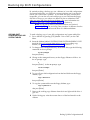
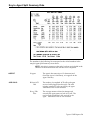
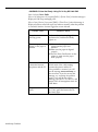
Section 4: Administering CMS
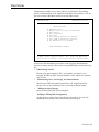
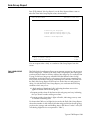
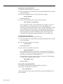
Overview
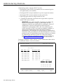
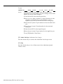
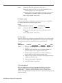
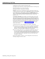
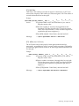
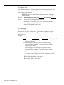
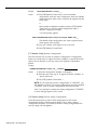
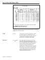
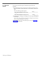
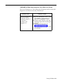
Administration enables you to tailor CMS for your business. The starting
point for administration is the Administration Menu, shown below. You can
get to it from the CMS Menu and from several other screens.
ADMIN CMS1.O 9:35a 04/18
ADMINISTRATION MENU
F1
F2
F3
F4
F5
F6
F7
F8
Administration Menu
Administer Stations
Administer Lines, Line Groups and Announcements
Agent Directory
Shift Configurations
Set Options
Select Exception Thresholds to be Monitored
Print SYSTEM 25 Administration Instructions
Exit Administration (Go to CMS MENU)
SELECT ADMINISTRATION FUNCTION
F1O - Help
F Admin F Lines/ F Agent F Config F Set F Select FS25 Admn F Exit
lStations 2Line Gps 3Directry 4 List 5 Options 6Exceptns 7Instrctn 8 Admin
As the list in the information area of the screen suggests, administration
involves a variety of tasks. These tasks are explained briefly in the following
list:
• Administering Stations
Identify each agent station by PDC, port number, and type of voice
terminal. Identify the PDC and port numbers of the supervisor station(s)
and PC jacks.
•
Administering Lines, Line Groups, and Announcements
Identify your CMS and transfer-queue lines, and assign them to line
groups. You can also administer your voice announcement unit(s).
•
Building the Agent Directory
Enter the name and CMS ID of each agent.
Building or Editing Shift Configurations
Assign agents to splits, and assign splits to line groups. You can also
administer Answer Delay and/or Force Delay for each split.
Overview 4-1
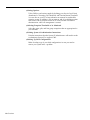
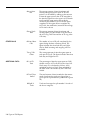
● Setting
Options
Tailor CMS to your business needs by defining your Service Level Limit,
Abandoned vs. Incoming Call Threshold, and Transfer Return Threshold.
You can also set your PC to beep whenever an unusual or undesirable
situation occurs. In addition, you can turn on and off a validation option
that causes CMS to perform a check of PC-Port Personal Line button
administration when call management is started.
● Selecting
Exception Thresholds to be Monitored
Select the agent, split, and line group exceptions that are appropriate for
your business.
● Printing
System 25 Administration Instructions
Print the instructions that the System 25 Administrator will need in order
to administer System 25 to support CMS.
● Backing
Up Shift Configurations
Make a backup copy of your shift configurations in case you need to
restore your system after a problem.
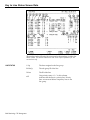
4-2 Overview
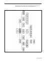
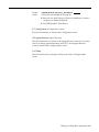
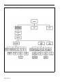
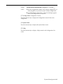
The map of the CMS Administration screens in Figure 4-1 illustrates the
interrelationships of the screens used for CMS administration.
FIGURE 4-1 Menu Map for CMS Administration.
Overview 4-3
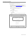
Getting Started
These procedures describe turning on the PC and selecting an administration
activity from the Administration Menu.
STARTING CMS
ADMINISTRATION
To start administering CMS:
1 Make sure the PC’s floppy drive is empty; then turn on your PC.
The AUTOEXEC.BAT file, installed on your PC’s hard disk during the
CMS installation process, causes the CMS Menu to be displayed
automatically after MS-DOS Resident Diagnostics are run. (For more
information, see “The AUTOEXEC.BAT File” in Section 3.)
NOTE: If the PC is already on and the C> prompt appears, do the
following to display the CMS menu:
a Type cd \cms and press [Enter].
b Type cms and press [Enter].
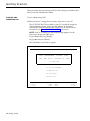
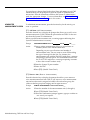
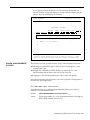
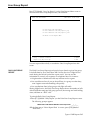
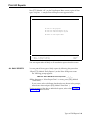
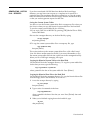
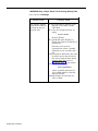
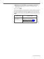
The CMS Menu, shown below, appears.
CMS MENU
CMS CMS1.09:19a 04/18
CALL
FOR
MANAGEMENT
THE
AT&T
SYSTEM
SYSTEM
(CMS)
25
PBX
(c) 1988 by AT&T
F1 Start Call Management
F4 Administer CMS
F5 Print Reports
F8 Exit to DOS
F Start
1 Call Mgt
4-4 Getting Started
F Admin
4 CMS
F Print
5 Reports
F10 - Help
F Exit
8 to DOS
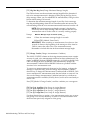
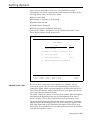
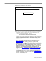
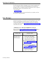
2 Press [F4] (labeled “Admin CMS”) to begin administering CMS.
The Administration Menu screen, shown below, appears.
ADMINISTRATION MENU
F1
F2
F3
F4
F5
F6
F7
F8
ADMIN CMS1.O 9:35a 04/18
Administration Menu
Administer Stations
Administer Lines, Line Groups and Announcements
Agent Directory
Shift Configurations
Set options
Select Exception Thresholds to be Monitored
Print SYSTEM 25 Administration Instructions
Exit Administration (Go to CMS MENU)
SELECT ADMINISTRATION FUNCTION
F1O - Help
F Admin F Lines/ F Agent F Config F Set F Select F S25 Admin F Exit
1 Stations 2 line Gps 3 Directry 4 List 5 Options 6 Exceptns 7 Instrctn 8 Admin
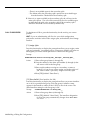
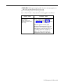
3 Press the function key for the administration activity you want to
perform. Turn to the corresponding instructions in this section of the
manual.
Getting Started 4-5
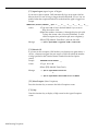
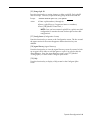
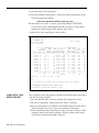
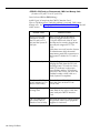
Administering Stations
Administering stations with the CMS PC involves:
• Entering the System 25 PDC, port number, and voice terminal type for
each agent station (voice terminal)
• Entering the PDCs and port numbers for up to two supervisor stations
• Entering the PDCs and port numbers for the two PC jacks
• Removing agent stations no longer needed for CMS
•
Changing the information associated with an agent station, supervisor
station, or PC jack, as needed
IMPORTANT: Port number and PDC assignments are made by the
System 25 Administrator. Changes in port number and PDC
assignments should not be made without consulting the System 25
Administrator. System 25 and CMS must reflect the same
assignments of port numbers, PDCs, and voice terminal type for
correct operation of CMS. If you make any additions, deletions, or
changes when administering stations that require System 25
administration, CMS prompts you to print System 25 administration
instructions when you attempt to exit CMS administration. You must
print the System 25 administration instructions and have your System
25 Administrator administer System 25 to reflect these changes.
Otherwise, CMS may not function properly. For more information,
see “Printing Administration Instructions,” later in this section.
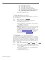
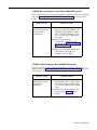
Pressing [F1] (labeled “Admin Stations”) on the Administration Menu selects
the Administer Stations screen shown below.
ADMINISTER STATIONS
ADMIN CMS1.0 9:44a 04/19
AGENT STATIONS
PDC
401
402
403
404
405
406
407
408
409
410
Port#
11101
11102
11103
11104
11105
11106
11107
11108
11201
11202
Type
304
304
304
304
304
304
304
304
304
304
PDC Port# TYPE
411 11203 304
412 11204 304
413 11205 304
414 11206 304
415 11207 304
416 11208 308
417 11004 304
418 11006 304
424 10902 307
Other Connections
USE
PDC Port #
SUPVR STA: 430 11001
431 11002
PC Jack CU1: 600 11003
PC Jack CU2: 601 11005
F Add
F Remove F Change
1 Agnt Stn 2 Agnt Stn 3 Agnt Stn
4-6 Administering Stations
F Admin F Admin
5 Supervsr 6 PC Jacks
F10 - Help
F Admin
8 Menu
This section describes the following activities which you can perform from the
Administer Stations screen:
●
Adding an Agent Station
Add an agent station to CMS.
●
Removing an Agent Station
Take an agent station out of CMS use.
●
Changing Agent Station Information
Change an agent station’s port number or voice terminal type.
●
Administering the Supervisor Station(s)
Identify the System 25 PDC and port number of each supervisor station,
●
Administering PC Jacks
Identify the PDCs and port numbers for the two PC jacks.
ADMINISTER STATIONS
SCREEN
When administering stations, keep the CMS Station Assignments Planning
form handy. This form includes information about your agent stations,
supervisor stations, and PC jacks.
To administer stations, press the function key for the activity you want to
perform:
[F1] Add Agnt Stn (Add Agent Station)
Press this function key to display the prompt that allows you to add an agent
station to CMS by identifying its System 25 PDC and port number, and its
voice terminal type. You must obtain the PDC and port number from the
System 25 Administrator.
Prompt:
ADD AGENT STATION: PDC:
Action:
1 Enter the System 25 PDC (maximum of 4 digits).
Port #:
Type:
2 Enter the System 25 port number (5 digits).
3 Enter the number that corresponds to the type of voice
terminal:
302 = 5-Button
303 = 10-Button Hands-Free Answer on Intercom (HFAI)
304 = 10-Button Built-in Speakerphone (MS)
304 = 10-Button
305 = 22-Button BIS (without headset)
305 = 34-Button BIS (without headset)
305 = 34-Button BIS, Deluxe (without headset)
305 = 34-Button BIS with Display (without headset)
305 = 34-Button Deluxe BIS with Display (without headset)
307 = 34-Button
307 = 34-Button Deluxe
Administering Stations 4-7
308 = 22-Button BIS (with headset)
308 = 34-Button BIS (with headset)
308 = 34-Button BIS, Deluxe (with headset)
308 = 34-Button BIS with Display (with headset)
308 = 34-Button Deluxe BIS with Display (with headset)
309 = 34-Button Direct Trunk Attendant Console (DTAC)
311 = Switched Loop Attendant Console, Deluxe
4 Press [F8] (labeled “Enter Data”).
[F2] Remove Agnt Stn (Remove Agent Station)
Press this function key to display the prompts that allow you to remove an
agent station from CMS.
Prompt:
Action:
REMOVE AGENT STATION: PDC:
1 Enter the PDC of the agent station to be removed.
2 Press [F8] (labeled “Enter Data”).
3 When the confirmation prompt appears, type y to confirm
your request or n to cancel it.
4 Press [F8] (labeled "Enter Data").
NOTE: Removing an agent station may cause inaccuracies in the
historical data. Therefore, if you have been managing calls with
CMS and decide to remove an agent station, print any
outstanding historical reports before you remove the agent station.
(See Section 7, “Generating CMS Reports.”) If you archive the
data, be sure to copy the old system tables, too. (For more
information, see Section 8, “Archiving Data.”)
[F3] Change Agnt Stn (Change Agent Station Information)
Press this function key to display the prompt that allows you to change an
agent station’s port number and/or voice terminal type. You cannot change
an agent station’s PDC with this function key. To change an agent station’s
PDC, you must first remove the station by pressing [F2] (labeled “Remove
Agnt Stn”), and then add the station with the correct PDC by pressing [F1]
(labeled “Add Agnt Stn”).
Prompt:
CHANGE AGENT STATION INFO: PDC:
Action:
1 Enter the PDC of an agent station displayed on the screen.
Port #:
T y p e :
2 Enter the new port number. Leave the field blank if you don’t
want to change it.
3 Enter the new voice terminal type. Leave the field blank if
you don’t want to change it.
4 Press [F8] (labeled “Enter Data”).
4-8 Administering Stations
[F5] Admin Supervsr (Administer Supervisor Station)
Press this function key to display the prompt that allows you to add a
supervisor station to CMS or to change supervisor station information
displayed on the screen. You can enter data for either one or two supervisor
stations. To change a field, enter information only in the field you want to
change.
Prompt:
2nd PDC:
SUPERVISOR STATION(S): PDC: Port #:
Action:
2nd Port #:
1 Enter the PDC for the first supervisor station.
2 Enter the System 25 port number for the first supervisor
station.
3 Enter the PDC for the second supervisor station.
4 Enter the System 25 port number for the second supervisor
station.
5 Press [F8] (labeled “Enter Data”).
[F6] Admin PC Jacks (Administer PC Jacks)
The AT&T CMS PC Interface Card in the PC has two connections (labeled
CU1 and CU2) for wiring to System 25. Use this function key to administer
the two CMS PC jacks by identifying their System 25 PDCs and port
numbers. You must obtain the PDCs and port numbers from the System 25
Administrator.
Prompt:
PC JACKS: CU1-PDC: CU1-Port#:
Action:
CU2-PDC:
CU2-Port#:
1 Enter the PDC for PC jack CU1.
2 Enter the System 25 port number for PC jack CU1.
3 Enter the PDC for PC jack CU2.
4 Enter the System 25 port number for PC jack CU2.
5 Press [F8] (labeled “Enter Data”).
[F8] Admin Menu (Administration Menu)
Press this function key to return to the Administration Menu screen.
[F10] Help
Press this function key to view a Help screen for the Administer Stations
screen.
Administering Stations 4-9
Administering CMS Lines and Line Groups
Your CMS supports up to 28 lines, including both CMS and transfer-queue
lines. (Refer to the next section, “Administering Transfer-Queue Lines,” for
more information.) You can arrange your lines in up to four line groups. If
you want, you can assign all your lines to a single line group.
You can also divide lines into sub-groups (for reporting purposes), and/or
assign priority to lines. The priority of a line determines its position in the
queue of calls waiting to be transferred to an agent. Calls on priority lines are
answered before older calls on non-priority lines. Priority lines are identified
by a “+” in the Priority (P) column of the Administer Line Groups screen.
Pressing [F2] (labeled “Lines/Line Gps”) on the Administration Menu screen
selects the Administer Line Groups screen, shown below. Use this screen to:
● Identify
● Assign
the CMS lines (Central office trunks) that are part of CMS.
CMS lines to line groups.
● Change
CMS line information (including line priority).
● Assign
or change line group IDs.
● Access
the screen for administering transfer-queue lines.
● Access
the screen for administering voice announcement units.
ADMINISTER LINE GROUPS
ADMIN CMS1.0 2:52p 04/18
LINE GROUPS
I -------------Line--- ”---------l I -------------Line --, ----------l
Group SbGrp Port# ID Tk# Typ P
Tk # Typ P
Group SbGrp Port# ID
C CHART CL 10603 L1234 1234 G
A PUBLC PL 10401 L3070 3070 G
PL 10402 L3071 3071 G
CL 10604 L1235 1235 G
PL 10403 L3072 3072 G
CW 106O5 W3000 3000 G
PL 10404 L3073 3073 G
CW 10606 W3001 3001 G
PW 10405 W4185 4185 G
CW 10607 W3002 3002 G
PW 10406 W4186 4186 G
PS 10407 S4950 4950 G + D
PS 10408 S4951 4951 G +
Q1 10701 Q500 8000 L +
B BUSNS
BW
BW
BW
BW
BL
BL
10501
10502
10503
10504
10601
10602
W1242
W1243
W1244
W1245
L8300
L8301
1242
1243
1244
1245
8300
8301
G
G
G
G
G
G
F Add CMS F Remove F Move CMS FChg CMS FAsgn/Chg F Admin F Admin
1 Line 2CMS Line 3 Line
4LineInfo 5Group ID 6Xfr Que 7 Anncs
4-10 Administering CMS Lines and Line Groups
F10 - Help
F Admin
8 Menu
ADMINISTER LINE
GROUPS SCREEN
To administer lines and groups:
.
●
Keep your CMS Line Groups Planning Form handy. It includes
information about each of your CMS lines and line groups.
●
Press the function key for the activity you want to perform.
●
Perform the activity according to the instructions on the following pages.
NOTE: When you add, remove, or move a line, or add, remove or change
the sub-group of a line, inaccuracies may occur in the historical data,
Therefore, if you have been managing calls with CMS and decide to make
any of the above changes, print out any outstanding historical reports
before you make the changes. (See Section 7, “Generating CMS Reports.”)
If you archive the data, be sure to copy the old system tables, too. (For
more information, see Section 8, “Archiving Data.”)
If you add or remove a CMS line, or if you change the port number, trunk
number, or line type of a CMS line, CMS prompts you to print the
System 25 Administration instructions when you attempt to exit CMS
Administration. You must print the administration instructions and have
your System 25 Administrator administer System 25 to reflect these
changes. Otherwise, CMS may not function properly. For more
information, see “Printing System 25 Administration Instructions,” later in
this section.
IMPORTANT: The instructions below cannot be used to administer
transfer-queue lines. To administer transfer-queue lines, press [F6]
(labeled “Admin Xfr Que”), and follow the instructions in the next
part of this section, “Administering Transfer-Queue Lines.”
[F1] Add CMS Line
Press this function key to display the prompt that allows you to add a CMS
line and assign it to a line group. Obtain the port number, trunk number and
trunk type from the System 25 Administrator.
Prompt:
ADD LINE: Grp (A-D):__ SubGrp:___ Port # :_______ ID:______ Trunk #:_______ Type:
Action:
1
2
Enter the letter (A through D) for the line group to which you
are assigning the line.
If you want to keep track of sub-groups within a line group,
such as the WATS lines, enter up to two numbers, letters, or
special characters for the sub-group in which the line is to be
included. (You can have a maximum of seven sub-groups for
each line group.)
Otherwise, press [F6] (labeled “Next Field”) to skip the
SubGrp field.
3
Enter the 5-digit System 25 port number.
Administering CMS Lines and Line Groups 4-11
4 Enter a unique line ID of up to five letters or numbers to help
you identify the line. You may want to use the last four digits
of the telephone number, an ID which associates the line with
a particular line group (such as SERV1 or SALE1), or an ID
which indicates the type of line (such as WATS1).
NOTE: A CMS line ID cannot begin with the letter “Q.” Only
transfer-queue lines can have ID’s beginning with a “Q.”
5 Enter the 4- digit System 25 trunk number (0001 through 9999).
6 In the Type field, enter G for a Ground Start trunk or L for a
Loop Start trunk.
7 Press [F8] (labeled "Enter Data").
NOTE: To assign priority to the line, use [F4] (labeled "Chg CMS
Line Info").
[F2] Remove CMS Line
Press this function key to display the prompts that allow you to remove a
CMS line.
Prompt:
REMOVE CMS LINE: Port #:
Action:
1 Enter the System 25 port number of a line displayed on the
screen.
2 Press [F8] (labeled “Enter Data”).
3 When the confirmation prompt appears, type y to confirm
your request or n to cancel it.
4 Press [F8] (labeled “Enter Data”).
[F3] Move CMS Line
Press this key to display the prompt that allows you to shift a line from one
line group to another.
Prompt:
MOVE CMS LINE: Line ID:
Action:
1 Enter the ID of the line to be moved.
to Group (A-D): _
2 Enter the letter (A through D) of the group to which the line is
to be moved.
3 Press [F8] (labeled “Enter Data”).
4-12 Administering CMS Lines and Line Groups
[F4] Chg CMS LineInfo (Change CMS Line Information)
Press this function key to display the prompts that allow you to:
● Add,
delete, or change a CMS line’s sub-group
● Change
the System 25 port number of a CMS line
● Change
the line ID of a CMS line
● Change
the System 25 trunk number of a CMS line
● Change
the trunk type of a CMS line
● Turn
priority on or off for a CMS line
Prompt:
CHANGE CMS LINE INFORMATION: for Old Line ID:
Action:
1 Enter the line ID of the line to be changed.
2 Press [F8] (labeled “Enter Data”).
A second prompt appears:
Prompt:
Line XXXXX: SbGrp:_____ Prt#:
ID:
Trk#:______ Typ:_____ Pri(ON/OFF):_____
(where XXXXX is the Line ID).
Action:
Enter information only in the field(s) you want to change. Leave
a field blank if you do not want to change it.
1 Enter up to two letters, numbers, or special characters for the
sub-group in which the line is to be included, or enter a
hyphen (-) if you do not want the line to be in a sub-group.
2 Enter the new 5-digit System 25 port number.
3 Enter the new line ID (up to 5 letters and/or numbers).
4 Enter the new 4-digit System 25 trunk number.
5 Enter the new trunk type, G for a Ground Start trunk or L
for a Loop Start Trunk.
6 Enter on to turn priority on for the line, or off to turn the
line priority off.
7 Press [F8] (labeled "Enter Data").
Administering CMS Lines and Line Groups 4-13
[F5] Assgn/Chg Group ID (Assign/Change Group ID)
Press this function key to display the prompt that allows you to assign or
change a line group’s ID. IDs help you identify the line groups on the status
screens and reports. A line group and a split can have the same ID.
Prompt:
ASSIGN/CHANGE GROUP ID: Group (A-D): _ New ID:
Action:
1 Enter a line group letter (A through D).
2 Enter the new line group ID (up to 5 letters or numbers).
3 Press [F8] (labeled “Enter Data”).
[F6] Admin Xfr Que (Administer Transfer-Queue Lines)
Press this function key to display the screen you use to administer lines for
the Transfer-into-Queue feature. See the next heading in this section.
[F7] Admin Anncs (Administer Announcements)
Press this function key to display the screen you use to administer voice
announcement units. This function is described later in this section.
[F8] Admin Menu (Administration Menu)
Press this function key to return to the Administration Menu.
[F10] Help
Press this function key to display a Help screen for the Administer Line
Groups screen.
4-14 Administering CMS Lines and Line Groups
Administering Transfer-Queue Lines
Each line group can have up to three transfer-queue lines assigned to it. Each
transfer-queue line is automatically assigned as a priority line. The priority
status of a transfer-queue line can only be changed from the Line Status
screen. (See “Using the Line Status Screen” in Section 5.) Transfer-queue
lines allow an agent to transfer a call to another line group’s queue. When
the call is received by that line group, it is then treated as a new incoming
CMS call. It is important to note that transfer-queue lines cannot be used to
make outside calls.
A Loop Start trunk port and a single-line station port are associated with each
transfer-queue line.
CMS automatically assigns each transfer-queue line a line ID that cannot be
changed. This is designated by a “Q” followed by the PDC of the single-line
station.
Pressing [F6] (labeled “Admin Xfr Que”) on the Administer Line Groups
screen selects the Administer Queued Transfer screen, shown below.
ADMIN CMS1.0 2:54p 04/18
ADMIN QUEUED TRANSFER
LINE GROUPS
|------------ Trunk Port ---------------|
Group SubGrp Port# ID
Trk# Type Prior
+
10701 Q500 8000 L
A PUBLIC Q1
F Add Xfr F Remove F Move Xfr F Chg Xfr
l Que Line 2 Que Line 3 Que Line 4 Que Info
|-Single-Line Port-|
Port#
10801
F10 - Help
F Admin
8 LineGrps
On this screen you can:
•
Add transfer-queue lines
•
Remove transfer-queue lines
•
Move transfer-queue lines
•
Change transfer-queue line information
Administering CMS Lines and Line Groups 4-15
ADMINISTER QUEUED
TRANSFER SCREEN
To administer transfer-queue lines:
● Keep
the Transfer-into-Queue Planning Form handy.
● Press
the function key for the activity you want to perform
NOTE: When you add, remove, or move a transfer-queue line, or add,
remove, or change the sub-group of a transfer-queue line, inaccuracies
may occur in the historical data. Therefore, if you have been managing
calls with CMS and decide to make changes to transfer-queue line
administration, print any outstanding historical reports before you make
the changes. (See Section 7, “Generating CMS Reports.”) If you archive
the data, be sure to copy the old system tables as well. (For more
information, see Section 8, “Archiving Data.”)
If you add or remove a transfer-queue line, or if you change the port or
trunk number of the associated Loop Start trunk, or the PDC or port
numbers of its associated single line station, CMS prompts you to print
System 25 administration instructions when you attempt to exit CMS
administration. You must print the administration instructions and have
your System 25 Administrator administer System 25 to reflect these
changes. Otherwise, CMS may not function properly. For more
information, see “Printing System 25 Instructions, ” later in this section.
[F1] Add Xfr Que Line (Add Transfer-Queue Line)
Press this function key to display the prompts that allow you to add a
transfer-queue line.
Prompt:
ADD TRUNK PORT FOR XFR QUEUE: Grp (A-D):
Action:
SubGrp:
Port #:
Trunk#:
Enter the letter of the line group (A through D) to which the
transfer-queue line is to be assigned.
1
2
Enter up to two letters, numbers, or special characters for the
line sub-group in which the transfer-queue line is to be
included. Leave this field blank if there is to be no sub-group
assignment.
3 Enter the 5-digit System 25 port number of the trunk port
associated with the transfer-queue line.
4
Enter the 4-digit System 25 trunk number of the trunk port
associated with the transfer-queue line.
5
Press [F8] (labeled “Enter Data”).
After the validation check has been passed, a second prompt appears:
Prompt:
ADD SINGLE-LINE PORT: PDC:
Action:
1 Enter the System 25 PDC of the single-line port associated
with the transfer-queue line.
Port #:
2 Enter the System 25 port number of the single-line port
associated with the transfer-queue line.
3 Press [F8] (labeled “Enter Data”).
4-16 Administering CMS Lines and Line Groups
[F2] Remove Que Line (Remove Transfer-Queue Line)
Press this function key to display the prompts that allow you to remove
a transfer-queue line. The information for both the trunk port and the
single-line station port associated with the transfer-queue line is removed
when you use this function.
Prompt:
REMOVE TRANSFER QUEUE LINE: Port #:
Action:
1 Enter the port number of the trunk associated with the
transfer-queue line.
2 Press [F8] (labeled "Enter Data").
3 When the confirmation prompt appears, type y to confirm
your request, or n to cancel it.
4 Press [F8] (labeled “Enter Data”).
[F3] Move Xfr Que Line (Move Transfer-Queue Line)
Press this function key to display the prompt that allows you to move the
transfer-queue line to a different line group.
Prompt:
MOVE TRANSFER QUEUE LINE: ID:
Action:
1 Enter the ID of the transfer-queue line to be moved.
to Group (A-D):___
2 Enter the letter of the line group (A through D) to which the
line is to be moved.
3 Press [F8] (labeled “Enter Data”).
[F4] Chg Xfr Que Info (Change Transfer-Queue Line Information)
Press this function key to display the prompt that allows you to:
●
Change the sub-group of the transfer-queue line
●
Change the System 25 port number of the trunk port associated with the
transfer-queue line
●
Change the System 25 trunk number of the trunk port associated with the
transfer-queue line
●
Change the PDC of the single-line port associated with the transfer-queue
line
●
Change the System 25 port number of the single-line port associated with
the transfer-queue line
NOTE: If you need to change the priority status of a transfer-queue line,
you must do so from the Line Status screen. See “Using the Line Status
Screen” in Section 5.
Administering CMS Lines and Line Groups 4-17
Prompt:
CHG INFO: ID:
Action:
SbGrp:
Tk Prt#:
T r k # :
P D C :
SL Prt#:
You must enter the ID; the other fields are optional. Enter
information only in the field(s) you want to change. Leave a field
blank if you do not want to change it.
1 Enter the line ID of the transfer-queue line.
2 Enter up to two letters, numbers, or special characters for the
sub-group in which the line is to be included, or enter a
hyphen (-) if you do not want the line to be in a sub-group.
3 Enter the new System 25 port number for the associated trunk
port.
4 Enter the new System 25 trunk number for the associated
trunk port.
5 Enter the new PDC for the single-line port.
6 Enter the new System 25 port number for the single-line port.
7 Press [F8] (labeled “Enter Data”).
[F8] Admin LineGrps (Administer Line Groups)
Press this function key to return to the Administer Line Groups screen.
[F10] Help
Press this function key to view a Help screen for the Administer Queued
Transfer screen.
4-18 Administering CMS Lines and Line Groups
Administering Announcements
Your CMS supports up to four voice announcement units for providing delay
messages to callers. The voice announcement units are connected to System
25 ports and have PDCs associated with them.
To administer voice announcement units, press [F7] (labeled “Admin Anncs”)
on the Administer Line Groups screen. The Administer Announcement
screen, shown below, appears.
ADMIN CMS1.0 2:57p 04/18
ADMINISTER ANNOUNCEMENT
ADMINISTER ANNOUNCEMENTS
ANNC ID
PORT#
PDC
1
PUBLIC
10802
610
2
BUSINES
10803
611
3
CHARTER
10804
612
4
F10 - Help
F Assign F Admin F Admin
6 Anncs 7 lineGrps 8 Menu
F Add
F Remove F Change
l Annc 2 Annc 3 Annc
With this screen you can:
●
Add an announcement unit by entering its announcement ID, System 25
port number, and PDC
●
Remove an announcement unit
●
Change the information (announcement ID, port number, or PDC)
pertaining to an announcement unit
●
Access the screen used to assign announcements to line groups, specify
the message length of each announcement unit, and put an
announcement unit in or out of service
You can return to the Administer Line Groups screen or Administration
Menu from the Administer Announcement screen by pressing [F7] or [F8] ,
respectively.
NOTE: The following require System 25 administration:
– Adding a voice announcement unit
– Removing a voice announcement unit
– Changing the PDC or port number of a voice announcement unit
Administering CMS Lines and Line Groups 4-19
If you make any changes listed in the above Note and attempt to exit CMS
administration, you are prompted to print the System 25 administration
instructions. Print the instructions and have the System 25 Administrator
make the appropriate changes. For more information, see “Printing System
25 Administration Instructions, ” later in this section.
ADMINISTER
ANNOUNCEMENT SCREEN
To administer announcements, press the function key for the activity you
want to perform:
[F1] Add Annc (Add Announcement)
Press this function key to display the prompt that allows you to add a voice
announcement unit to CMS. Obtain the port number and PDC for the new
unit from the System 25 Administrator.
When you add an announcement unit, a warning appears indicating that
System 25 administration is necessary.
Prompt:
ADD ANNOUNCEMENT: Anne ID:
Action:
1 Enter a unique announcement ID (up to seven letters or
numbers) for the voice announcement unit.
Port #:
PDC:_______
Depending on your type of business and number of
announcement units, you may want to use an ID describing
the type of message on that unit. For instance, the
announcement unit with the ID SALES might have a message
advertising a seasonal special. The announcement unit with
the ID ACCTNO might have a message requesting customers
to have their account numbers ready.
2 Enter the System 25 port number.
3 Enter the PDC.
4 Press [F8] (labeled “Enter Data”).
[F2] Remove Annc (Remove Announcement)
Press this function key to display the prompts that allow you to remove a
voice announcement unit from CMS. If you remove a voice announcement
unit and no other unit is assigned to handle calls on that line group, the
callers to that line group hear ringing until an agent answers.
Prompt:
Action:
REMOVE ANNOUNCEMENT: Announcement Number___
1 Enter the number of the announcement unit (1 through 4).
2 Press [F8] (labeled “Enter Data”).
3 When the confirmation prompt appears, type y to confirm or
n to cancel your request.
4 Press [F8] (labeled “Enter Data”).
4-20 Administering CMS Lines and Line Groups
[F3] Change Annc (Change Announcement Information)
Press this function key to display the prompt that allows you to update or
correct the ID, System 25 port number, or PDC for a voice announcement
unit. Unless you are correcting a typing error, changing a port number or
PDC also requires System 25 administration.
Prompt:
CHANGE ANNC INFO: Annc #:__ Annc ID:
Action:
1
Port #:
PDC:
Enter the number of the announcement unit you want to
change (1 through 4).
2
Enter the new announcement ID or leave the field blank if you
don’t want to change it.
3
Enter the new System 25 port number or leave the field blank
if you don’t want to change it.
4
Enter the new System 25 PDC or leave the field blank if you
don’t want to change it.
5
Press [F8] (labeled “Enter Data”).
NOTE: If you enter an announcement number and press [F8] without
changing the information in any field, the data for that voice
announcement unit stay the same.
[F6] Assign Anncs (Assign Announcements)
See the following heading “Assigning Announcements.”
[F7] Admin LineGrps (Administer Line Groups)
Press this function key to return to the Administer Line Groups screen.
[F8] Admin Menu (Administration Menu)
Press this function key to return to the Administration Menu.
[F10] Help
Press this function key to view a Help screen for the Administer
Announcement screen.
Administering CMS Lines and Line Groups
4-21
Assigning Announcements
Certain information about the daily use of voice announcement units is
administered from the Assign Announcement screen. To reach the Assign
Announcement screen, you must first select an announcement from the Select
Announcement screen. Press [F6] (labeled “Assign Anncs”) on the
Administer Announcement screen to reach the Select Announcement screen,
shown below.
ADMIN CMS1.O 3:07p 04/18
SELECT ANNOUNCEMENT
ANNOUNCEMENT ASSIGNMENTS
MAX MSG ANNC LINE GP A LINE GP B LINE GP C LINE GP D
ANNC# ANNC ID LENGTH CONDTN PUBLIC BUSNS CHART x
1
PUBIC
18 sec REMVD
2
BUSINES
15 sec AVAIL -
3
CHARTER
13 sec AVAIL -
x
x
4
F Select
l Annc
F1O - Help
F Admin
8 Anncs
SELECT ANNOUNCEMENT To select an announcement from the Select Announcement screen:
SCREEN
1 Press [F1] (labeled “Select Annc”) to select a particular voice
announcement unit.
The following prompt appears:
SELECT ANNOUNCEMENT: Announcement Number____
2 Enter the number of the voice announcement unit and press [F8] (labeled
“Enter Data”).
4-22 Administering CMS Lines and Line Groups
A box appears around the data for the voice announcement unit you
selected, and the screen title changes to Assign Announcement, and the
function keys are relabeled as shown below.
ADMIN CMS1.0 3:07p 04/18
ASSIGN ANNOUNCEMENT
ANNOUNCEMENT ASSIGNMENTS
MAX MSG ANNC LINE GP A LINE GP B LINE GP C LINE GP D
ANNC# ANNC ID LENGTH CONDTN PUBLC BUSNS CHART 1
PUBLIC
18 sec REMVD
x
2
BUSINES
15 sec AVAIL -
3
CHARTER
13 sec AVAIL -
x
x
4
F1O - Help
F Select F Chg Max FChange FLn Gp A FLn Gp B FLn Gp C FLn Gp D F Admin
l Annc 2 Msg Len 3Condtn 4 Asgn/Rmv 5 Asgn/Rmv 6 Asgn/Rmv 7 Asgn/Rmv 8 Anncs
ASSIGN ANNOUNCEMENT
SCREEN
The activities you can perform from the Assign Announcement screen are:
● Indicating
the maximum length of the Day Service message on a voice
announcement unit
● Changing
the condition (available, broken, or removed) of a voice
announcement unit in order to put it in or out of service.
● Assigning
a voice announcement unit to one or more line groups
Press the function key for the activity you want to perform. Descriptions of
the functions keys begin below.
[F1] Select Annc (Select Announcement)
Press this function key to display the prompt that allows you to select a
different voice announcement unit.
Prompt:
SELECT ANNOUNCEMENT: Announcement Number: ____
Action:
1 Enter the number of a voice announcement unit (1 through 4).
2 Press [F8] (labeled “Enter Data”) .
Administering CMS Lines and Line Groups 4-23
[F2] Chg Max Msg Len (Change Maximum Message Length)
The CMS software uses the maximum message length field to determine if
each voice announcement unit is hanging up after playing the Day Service
delay message. When you first administer an announcement, CMS gives this
field an initial setting of 10 seconds.
To determine the maximum message length of your Day Service message,
time the period beginning when the voice announcement unit answers the
call and ending when the voice announcement unit disconnects from the call.
NOTE: If the maximum message length you enter is less than the
actual Day Service delay message, CMS will indicate that the voice
announcement unit is broken when it is actually working properly.
Prompt:
Maximum Message Length in Seconds (1-999):____
Action:
1 Enter the maximum message length in seconds.
2 Press [F8] (labeled “Enter Data”).
IMPORTANT: When recording an announcement, leave three to four
seconds of silence at the beginning of the message to allow time for
CMS to connect the caller to the voice announcement unit.
Remember to include this time in the maximum message length.
[F3] Change Condtn (Change Announcement Condition)
The ANNC CONDTN column on the Assign Announcement screen contains
an entry for each voice announcement unit that has been administered. The
entries are BROKN (broken), REMVD (removed), or AVAIL (available). Only
CMS can change the entry to BROKN. CMS automatically changes the
Announcement Condition field to BROKN if it detects a problem with the
associated voice announcement unit.
To remove an announcement unit from service (for instance, to change the
message or repair the unit), press the Change Announcement Condition
function key to change the Announcement Condition field to REMVD. Calls
are not transferred to announcement units that are broken or removed. You
also use the Change Announcement Condition function key to indicate an
announcement unit is available (AVAIL), that is, back in service and ready to
receive calls.
Press [F3] (labeled “Change Condtn”) until the condition you want appears.
[F4]
[F5]
[F6]
[F7]
Ln Gp A Asgn/Rmv (Line Group A Assign/Remove)
Ln Gp B Asgn/Rmv (Line Group B Assign/Remove)
Ln Gp C Asgn/Rmv (Line Group C Assign/Remove)
Ln Gp D Asgn/Rmv (Line Group D Assign/Remove)
Use these function keys to assign a voice announcement unit to one or more
line groups. You also use these keys to remove voice announcement units
that have been previously assigned to a line group.
4-24 Administering CMS Lines and Line Groups
An X in the line group column for an announcement unit indicates that the
unit is assigned to that line group. A hyphen (-) indicates the unit is not
assigned to that line group.
To assign a voice announcement unit to a line group (or remove it from that
group) press the appropriate function key. As you press the function key, the
mark in the column toggles between “X” and “-”.
[F8] Admin Anncs (Administer Announcements)
Press this function key to return to the Administer Announcement screen.
[F10] Help
Press this function key to view a Help screen for the Assign Announcement
screen.
Administering CMS Lines and Line Groups 4-25
Creating an Agent Directory
The Agent Directory screen contains a "master list" of CMS agents. It lists all
CMS agents alphabetically by last name.
Each CMS agent needs a unique ID of up to 5 characters. You use this ID
when you add, remove, or move an agent. Agents are also identified by ID
in exception messages. You can assign up to 60 agent IDs. However, only 28
agents can be assigned to a single shift configuration.
Pressing [F3] (labeled “Agent Directry”) from the Administration Menu screen
selects the Agent Directory screen, shown below. Use this screen to add
agents, remove agents, or edit agent information.
AGENT DIRECTORY
ADMIN CMS1.0 2:31p 04/18
AGENT DIRECTORY
Last Name
Abell
Beckman
Brown
Chu
Dumbra
Fang
Fenton
Garcia
Gerkensmier
Johnson
Kesslering
Leonard
Lindquist
Lindquist
Mack
F Add
1 Agent
USING THE AGENT
DIRECTORY SCREEN
First
Mary-Ann
Jim
Allan
David
Marie
John
Scott
Jose
Otto
Andrew
Ana
Michael
Hal
Hal
Joel
F Remove F Change
2 Agent 3 Agt Name
ID
MARYA
JIM
ALLAN
DAVE
MARIE
JOHN
SCOTT
JOSE
OTTO
ANDY
ANA
MIKE
HAL1
HAL2
JOEL
Last Name First
Jane
Manetta
William
Masson
Ien
Ong
Joseph
Oplach
Louis
Reicheg
Rowlinson Don
Seiler
Linda
Siegl
Lawrence
Smith
Bernard
Son
Sarah
Stickler
Craig
Vaiter
Barbara
Jennifer
Walsh
Harvey
Woll
CJ
Yang
F Next
5 Page
ID
JANE
BILL
IEN
JOE
LOU
DON
LINDA
LARRY
BERNE
SARAH
CRAIG
BARB
JENNY
HARV
CJ
F1O - Help
F Config F Admin
7 Splits 8 Menu
To use the Agent Directory screen, press the function key for the activity you
want to perform:
[F1] Add Agent
Use this function key to add new agents to the Agent Directory. This activity
does not add agents to an active configuration; it merely identifies them in
the Agent Directory.
HINT: If any agent is regularly assigned to more than one split, create more
than one entry for the agent in the Agent Directory. Enter the agent with a
different ID for each split. Then use the appropriate ID when you add the
agent to a split. The different IDs permit separate tracking of the
agent’s statistics in each split. For example, Hal works in split 1 sometimes
and in split 2 other times. Hal’s supervisor added him to the directory once
with the ID HAL1 and again as HAL2.
4-26 Creating an Agent Directory
Prompt:
ADD AGENT: Last Name:
Action:
1 Enter the agent’s last name, up to 12 letters, numbers, or
special characters (such as * or #), with no spaces between
them. The last name appears in uppercase and/or lowercase
letters, exactly as you type it.
First:
I D :
2 Enter the agent’s first name, up to 8 letters, numbers, or
special characters, with no spaces between them. The first
name appears in uppercase and/or lowercase letters, exactly as
you type it.
3 Enter a unique agent ID, up to 5 letters or numbers. The ID
appears on the screen in uppercase letters, even if you enter
lowercase ones.
4 Press [F8] (labeled “Enter Data”).
[F2] Remove Agent
Press this function key to display the prompts that allow you to delete an
agent from CMS. To help you avoid removing an agent by accident, CMS
prompts you to confirm your request.
NOTE: Removing an agent from the Agent Directory will delete the
historical data for that agent. If you have any historical reports that
have not yet been printed, print them before you remove the agent.
Refer to Section 7 for information on generating CMS reports. (If you
are archiving the historical data, be sure to copy the system tables as
well as the data files. For more information, see Section 8, “Archiving
Data.”)
Prompt:
REMOVE AGENT: ID:
Action:
1 Enter the ID of the agent to be removed.
2 Press [F8] (labeled "Enter Data").
3 When the confirmation prompt appears, type y to confirm
your request or n to cancel it.
4 Press [F8] (labeled “Enter Data”).
[F3] Change Agt Name (Change Agent Name)
Press this function key to display the prompt that allows you to change an
agent’s last name or first name in the Agent Directory. (You cannot change
an agent’s ID using this function key. To change an agent’s ID, you must
first remove the agent and then add the agent with a different ID.)
Prompt:
CHANGE AGENT NAME: ID:
Last Name:
First:
Creating an Agent Directoy 4-27
Action:
1 Enter the agent ID as it appears on the screen.
2 Enter the new last name, or leave the field blank if you don’t
want to change it.
3 Enter the new first name, or leave the field blank if you don’t
want to change it.
4 Press [F8] (labeled “Enter Data”).
[F5] Next Page/Prev Page (Next Page/Previous Page)
If the Agent Directory contains more than 30 entries and the first page is
displayed, [F5] is labeled “Next Page.” Pressing this key allows you to look
at the second page of the Agent Directory. When the second page of the
Agent Directory is displayed, [F5] is labeled "Prev Page", and pressing it
returns you to the first page of the Agent Directory.
[F7] Config Splits (Configure Splits)
Press this function key to display the Configure Splits screen. This function
key works only if you have already selected a particular configuration to build
or edit. If you haven’t already selected a configuration, use the Configuration
List screen to select a configuration. You can access the Configuration List
screen by pressing [F4] (labeled “Config List” ) from the Administration Menu
screen.
[F8] Admin Menu (Administration Menu)
Press this function key to return to the Administration Menu screen.
[F10] Help
Press this function key to view a Help screen for the Agent Directory screen.
4-28 Administering CMS
Building or Editing Shift Configurations
A shift configuration is an arrangement of line groups and agent splits for
managing calls. Before CMS can begin managing calls, you must build at
least one shift configuration. You can build as many as six configurations to
handle different calling patterns in your business. For instance, a business
may require Day, Evening, and Weekend configurations.
CMS Night Service mode (which is different from System 25 Night Service)
can be used when no agents are on duty. During Night Service, CMS
connects all incoming calls to a voice announcement unit message and
automatically disconnects the calls when the message is over. For more
information, see “Selecting Day or Night Service” in Section 5.
In a shift configuration, splits are assigned to line groups as main splits and
secondary splits. A main split has primary responsibility for answering calls
for a line group (or line groups). A secondary split answers calls to a line
group only if all agents in the main split are busy or unavailable, intraflow is
turned on, and the Intraflow Threshold has been reached. (For more
information on intraflow, see “Administering Call Flow,“ later in this section.)
In the Day configuration for Bon Voyage Travel, main splits and secondary
splits are assigned like this:
Line Group
Main Split
Secondary Split
Public line
group
Public Travel
split
Support split
Business line
group
Business Travel
split
Charter Travel
split
Charter line
group
Charter Travel
split
Business Travel
split
Building or Editing Shift Configurations 4-29
Administering shift configurations begins with the Configuration List screen
shown below. Pressing [F4] (labeled “Config List” ) from the Administration
Menu screen selects this screen.
ADMIN CMS1.0 3:18p 04/18
CONIFIGURATION LIST
STORED SHIFT CONFIGURATIONS
1
2
3
4
5
6
— DAY
— EVENING
— WEEKEND
— UNUSED
— UNUSED
— UNUSED
F Select F Save F Rename F Choose
1 Config 2 Config 3 Config 4 Startup
F10 - Help
F Config F Admin
7 Screen 8 Menu
This section describes the following activities you can perform from the
Configuration List screen:
●
Selecting a Shift Configuration
Select a new shift configuration to build, or change (edit) an existing one.
●
Saving an Edited Configuration
Store the shift configuration that was last edited.
●
Renaming a Shift Configuration
Name, rename, or delete a shift configuration.
●
Selecting a Startup Configuration
Select one of your shift configurations to be invoked automatically during
the call management startup procedure.
●
Returning to Other Screens
If you press [F7] (labeled “Config Screen”), you return to the
Configuration screen for the cofiguration you last selected. (The name of
that configuration is shown in reverse video on the Configuration List
screen.) If you press [F8] (labeled “Admin Menu”), you return to the
Administration Menu screen.
4-30 Building or Editing Shift Configurations
Building or Editing a Shift Configuration
This section describes how to build a new shift configuration or change
(edit) an existing one. Your CMS cannot manage calls while you are using
these procedures. (To edit an active shift configuration without stopping
call management, follow the instructions in “Dynamic Reconfiguration” in
Section 5.)
Building or editing a shift configuration involves these activities:
●
Selecting the shift configuration you want to build or edit
●
Assigning agents to splits (up to 28 agents to a split, and a maximum of 28
agents to a shift configuration)
●
Administering call flow (assigning main and secondary splits to line
groups, administering intraflow)
●
Programming answer delay (the number of seconds a CMS call rings
before being connected to a voice announcement unit if no agents are
available to answer the call)
Programming force delay (an optional feature that causes all callers to hear
the entire delay message, even if an agent is available)
.
If you haven’t already done so, plan your shift configuration on a photocopy
of a Shift Configuration Planning Form. Make a photocopy of the Shift
Configuration Planning Form found behind the “Original Forms” tab in the
CMS binder. Refer to the completed form as you administer CMS.
●
HINT: If you are building a shift configuration similar to an existing one, edit
the existing configuration and save the changes in an unused configuration.
For instance, if you want to create a shift configuration similar to the shift 1
configuration you have already created, edit the shift 1 configuration and save
it in a previously unused configuration number.
BUILDING OR EDITING A
SHIFT CONFIGURATION
To build or edit a shift configuration:
1 Press [F1] (labeled “Select Config” ) on the Configuration List screen.
2 Respond to the prompt
SELECT CONFIGURATION: Config # (1-6):___
by entering the number of the shift configuration you want to create or
change.
3 Press [F8] (labeled “Enter Data”).
The Configuration screen appears with the shift configuration you
selected. The following example shows how the Configuration screen
looks when a configuration that has already been built is selected.
Building or Editing Shift Configurations 4-31
CONFIGURATION
ADMIN CMS1.0 3:20p 04/18
AGENT SPLITS
ANSWER/FORCE DELAY
|--Agent--|
|--Agent--|
Num Answer Force
Split PDC ID
Split PDC ID
Group Lines Delay Delay
A PUBLC 9
10s
Off
1 PUBLIC 401 LINDA 4 SPPT 417 CRAIG
B BUSNS 6
418 BARB
0s
On
402 JOEL
424 CJ
C CHART 5
5s
Off
403 IEN
D0
404 JENNY 5 5s
Off
405 SCOTT 6 406 BILL
2 BUSNS 407 SARAH
CALL FLOW
408 JOHN
Flow
409 JIM
|-Splits-|
Spl
Thresh
Intra
3 CHART 410 BERNE
50s
Gp Main Sec Flow 1
411 DON
2
30s
A 1 4 On
412 ALLAN
B 2 3 Off
3
30s
4 SUPPT 415 ANDY
C 3 2 Off
4
30s
416 LOU
D - - Off
5
30s
6
30s
Configuration #1 - DAY
F Splits FAns/Fore F Call
1
2 Delay 3 Flow
4-32 Building or Editing Shift Configurations
F Clear
5 Config
F10 - Help
F Config F Admin
7 List 8 Menu
The following Configuration screen illustrates a new configuration that has
yet to be built.
The items in the following list correspond to the circled letters in the
previous screen. They show the initial settings supplied for a new
configuration.
a
Split numbers 1 through 6 are displayed in the Agent Splits area.
b
Split IDs will be displayed if the splits have been previously named.
Otherwise, a hyphen (-) will appear in the “Split” column.
c
Answer delay is set to 5 seconds.
d
Force delay is turned off.
e
Main and secondary splits are unassigned (indicated by hyphens).
f
Intraflow is turned off.
g
Intraflow thresholds are set to 30 seconds.
4 Select the activity you want to perform from the following list and then
turn to the appropriate instructions.
—
Administering Splits
Add, move, or remove agents in the splits in the displayed
configuration, as well as change the split ID.
—
Administering Answer Delay and Force Delay
Administer how you want CMS to answer calls with respect to the
voice announcement unit(s).
Building or Editing Shift Configurations 4-33
– Administering Call Flow
Assign splits to cover line groups, turn intraflow on or off, or set
Intraflow Thresholds for splits.
– Clearing a Configuration
Delete the contents of a configuration.
– Returning to Other Screens
Return to the Configuration List screen by pressing [F7] (labeled
“Config List” ), where you can save the configuration you have just
built or edited. Return to the Administration Menu by pressing [F8]
(labeled "Admin Menu") to select another administration activity.
CONFIGURING SPLITS
The list of agents you created on the Agent Directory screen is your master list
of agents. Any agent in the Agent Directory can be assigned to a split. The
Administer Stations screen contains the master list of PDCs for agent stations.
You can assign only PDCs that appear in the Agent Stations section of the
Administer Stations screen.
Pressing [F1] (labeled “Splits”) from the Configuration screen selects the
Configure Splits screen shown below.
CONFIGURE SPLITS
ADMIN CMS1.O 3:27p 04/18
ANSWER/FORCE DELAY
AGENT SPLITS
Num Answer Force
❘ --Agent-- ❘
❘ ..Agent.. ❘
Group Lines Delay Delay
Split
Split PDC ID
PDC ID
Off
A PUBLIC 9
10S
1 PUBLIC401 LINDA 4 SUPPT 417 CRAIG
On
B
BUSNS
6
0S
418
BARB
402 JOEL
C CHART 5
Off
5S
424
CJ
403 IEN
D
Off
0
5S
5
404 JENNY
6
405 SCOTT
406 BILL
CALL FLOW
2 BUSNS 407 SARAH
Flow
408 JOHN
JIM
409
Spl Thresh
❘ -Splits- ❘ Intra
3 CHART
1
410 BERNE
50s
Gp Main Sec Flow
2
30s
On
A 1
411 DON
4
3
30s
Off
412 ALLAN
B 2
3
4
4 SUPPT
30s
Off
415 ANDY
2
C 3
5
30s
Off
516 LOU
D 30s
6
Configuration #1 - DAY
F Add
1 Agent
4-34 Building or Editing Shift Configurations
F Remove F Move
2 Agent 3 Agent
F1O - Help
F Replace F New
F Change F Config F Agent
5 Agent 6 Split ID 7 Screen 8 Directry
4 Agent
To configure splits, press the function key for the activity you want to
perform:
[F1] Add Agent
Press this function key to display the prompt that allows you to assign an
agent to a split. The agent must already be listed on the Agent Directory
screen and the station must already appear on the Administer Stations screen.
A split may have up to 28 agents. A total of 28 agents can be assigned to a
shift configuration.
HINT: If you want to add an agent who is not already in the Agent
Directory, use [F5] (labeled “New Agent”) instead of [F1].
Prompt:
ADD AGENT: ID:
Action:
1 Enter the ID of an agent listed in the Agent Directory.
PDC:
to Split #: _
2 Enter the System 25 PDC of an agent station displayed on the
Administer Stations screen.
3 Enter the split number (1 through 6).
4 Press [F8] (labeled “Enter Data”).
[F2] Remove Agent
Press this function key to display the prompts that allow you to remove an
agent from a split. (The agent will still be Listed on the Agent Directory
screen.)
Prompt:
REMOVE AGENT: ID:
Action:
1 Enter the ID for the agent you want to remove.
2 Press [F8] (labeled “Enter Data”).
3 When the confirmation prompt appears, type y to confirm
your request, or n to cancel it.
4 Press [F8] (labeled “Enter Data”).
[F3] Move Agent
Press this function key to display the prompt that allows you to move an
agent from one split to another and/or from one station to another.
Prompt:
MOVE AGENT: ID:
New PDC:
New Split #: _
Building or Editing Shift Configurations 4-35
Action:
1 Enter the ID for the agent you want to move.
2 Enter the agent’s new PDC or leave this field blank if you
want the agent to stay at the same station.
3 Enter the agent’s new split number (1 through 6) or leave this
field blank if you want the agent to stay in the same split.
4 Press [F8] (labeled “Enter Data”).
[F4] Replace Agent
Press this function key to display the prompt that allows you to substitute
one agent for another at a particular agent station.
Prompt:
REPLACE AGENT: Remove Agent ID:
Action:
and Add Agent ID:
1 Enter the ID of the agent to be replaced.
2 Enter the ID of the agent you want to substitute at that
station.
3 Press [F8] (labeled “Enter Data”).
[F5] New Agent
Press this function key to display the prompt that allows you to add an agent
who is not already listed on the Agent Directory screen to a split. The agent
is simultaneously added to the split and to the Agent Directory.
Prompt:
NEW AGNT: ID: ____ Last name:
Action:
1
First:
PDC:
Split#:___
Enter the agent ID, up to 5 letters or numbers. (IDs must be
unique.)
2
Enter the agent’s last name, up to 12 letters, numbers, or
special characters with no spaces between them.
3
Enter the agent’s first name, up to 8 letters, numbers, or
special characters with no spaces between them.
4
Enter the System 25 PDC of an agent station displayed on the
Administer Stations screen.
5
Enter the split number (1 through 6).
6
Press [F8] (labeled “Enter Data”).
[F6] Change Split ID
Press this function key to display the prompt that allows you to assign,
change, or delete the ID for a split. Split IDs carry through all shift
configurations. They make it easier to identify splits on screens and in
reports. Each split ID must be unique. However, a split and a line group can
have the same ID.
4-36 Building or Editing Shift Configurations
Prompt:
CHANGE SPLIT ID: Split # (l-6):_ New Split ID:
Action:
1 Enter the split number (1 through 6).
2 Enter the new split ID (up to 5 letters or numbers), or enter a
hyphen (-) to delete the split ID.
3 Press [F8] (labeled “Enter Data”).
[F7] Config Screen (Configuration Screen)
Press this function key to return to the Configuration screen.
[F8] Agent Directory (Agent Directory)
Press this function key to return to the Agent Directory screen if you need to
refer to or change agent information. Press [F7] on the Agent Directory
screen to return to the Configure Splits screen.
[F10] Help
Press this function key to display a Help screen for the Configure Splits
screen.
Building or Editing Shift Configurations 4-37
Administering Answer Delay and Force Delay
Pressing [F2] (labeled “Ans/Forc Delay”) from the Configuration screen
displays the Configure Delay screen, shown below.
CONFIGURE DELAY
Split
1 PUBLIC
2 BUSNS
3 CHART
4 SUPPT
AGENT SPLITS
|-Agent-|
|-Agent-|
PDC ID
Split PDC ID
4 SUPPT 417 CRAIG
401 LINDA
418 BARB
402 JOEL
424 CJ
403 IEN
5 404 JENNY
6 405 SCOTT
406 BILL
407 SARAH
408 JOHN
409 JIM
410 BERNE
411 DON
412 ALLAN
415 ANDY
416 LOU
ADMIN CMS1.0 3:31p 04/18
ANSWER/FORCE DELAY
N u m Answer Force
Group Lines Delay Delay
A PUBLC 9
10s Off
B BUSNS 6
0s On
C CHART 5
5s Off
D 0
5s Off
CALL FLOW
|-Splits-|
Gp Main Sec Flow
A 1 4 On
B 2 3 Off
C 3 2 Off
D - - Off
Flow
Spl Thresh
1 50s
2 30s
3 30s
4 30s
5 30s
6 30s
Configuration #1 - DAY
ANS/FORCE DELAY: Grp (A-D):___ Ans Delay (0-99 sec):___ Force Delay (ON/OFF):____
F Cancel
F Enter
F Previous F Next
8 Data
1 Prompt
5 Field 6 Field
From this screen, you can administer two delay options that affect the
handling of incoming calls: Answer Delay and Force Delay.
Answer Delay
The Answer Delay is the number of seconds CMS has a call wait before
connecting it to a voice announcement unit when no agents are available to
service the call. You may want to get some experience with CMS call
management before you change the answer delay from its initial setting of 5
seconds.
Think of Answer Delay as a trade-off between the time a customer spends
listening to ringing and the time the customer spends on hold. You can set a
different Answer Delay value for each line group, depending on the type of
lines in the group and the amount of time the caller is likely to wait before an
agent is available.
4-38 Building or Editing Shift Configurations
Consider these factors when choosing an Answer Delay value for a line
group:
● If
you have toll lines (such as 800 lines), you begin paying for a call as
soon as the line is answered by CMS. If calls are likely to be on hold
before an agent is available, increasing the Answer Delay value decreases
the time on hold, and, hence, the cost of the call.
● You
can increase the Answer Delay if you know callers will have to wait
for an agent. Callers may be less likely to hang up if they wait longer for
CMS to answer but spend less time on hold.
Force Delay
The Force Delay option controls the transfer of calls to and from the voice
announcement unit. If Force Delay is on, calls that arrive for a line group will
not be transferred to an agent until callers have heard the entire message,
even if an agent is available. This means that calls may be queued up waiting
to hear the delay message even when agents are available. If Force Delay is
off, they will be transferred to an agent as soon as one becomes available.
IMPORTANT: You must assign a voice announcement unit to a line
group before you can turn on Force Delay for that line group.
CONFIGURE DELAY
SCREEN
To administer Answer Delay or Force Delay:
Press [F2] (labeled “Ans/Fore Delay”) from the Configuration screen to select
this function. The screen title changes to “Configure Delay,” a box appears
around the Answer/Force Delay area of the screen and the following prompt
appears:
Prompt:
ANS/FORCE DELAY: Grp (A-D): __ Ans Delay (0-99 sec): __ Force Delay (ON/OFF):___
Action:
1 Enter a line group letter (A through D).
2 Enter the Answer Delay, the number of seconds (0 through 99)
you want calls to ring before CMS connects them to an
announcement unit if no agent is available to service the call.
Leave this field blank if you don’t want to change it.
The initial answer delay setting is 5 seconds, the approximate
time from the beginning of one ring to the beginning of the
next.
3 Type on to turn Force Delay on, or off to turn it off. Leave
this field blank to keep the current value. The initial setting
is off.
4 Press [F8] (labeled “Enter Data”).
Building or Editing Shift Configurations 4-39
Administering Call Flow
Administering call flow includes the following tasks:
● Assigning
● Turning
● Setting
a main split and a secondary split (optional) for each line group
intraflow on or off for a line group
an Intraflow Threshold for each split
Intraflow is the process of transferring calls from a main split’s queue to an
available agent in the secondary split. A main split has primary responsibility
for answering calls for a line group (or groups). A secondary split covers
calls to a line group only if all the agents in the main split for that line group
are busy or unavailable, the Intraflow Threshold has been reached, and
intraflow is on.
The Intraflow Threshold is the number of seconds the oldest call in a main
split’s queue must wait before it can be sent to an available agent (if there is
one) in the secondary split. This waiting time begins when the call first rings.
However, if calls already in the secondary split’s queue have exceeded its
Intraflow Threshold, the secondary split will not accept intraflowed calls until
these queued calls have been answered. For a detailed description of how
and when calls are intraflowed, see “How Intraflow Works” later in this
section of the manual.
Consider these points when establishing your Intraflow Threshold(s):
● How
long do you want your callers to wait for an agent in the main split
if there are agents available in your secondary split? (The waiting time
starts as soon as the call begins ringing.) Answering this question helps
determine a reasonable Intraflow Threshold for the main split.
● If
your secondary split serves as a main split for another line group, you
may not want that split to accept intraflowed calls if it is busy with its
own calls. The secondary split’s Intraflow Threshold determines how long
its own calls may wait before the split refuses to accept intraflowed calls.
(If a secondary split is not a main split as well, you don’t need to set a
threshold for that split.)
Pressing [F3] (labeled “Call Flow”) on the Configuration screen selects the
following Configure Call Flow screen.
4-40 Building or Editing Shift Configurations
CONFIGURE CALL FLOW
Split
1 PUBLC
2 BUSNS
3 CHART
4 SUPPT
ADMIN CMS1.0 3:32p 04/18
AGENT SPLITS
|--Agent--|
|--Agent--|
PDC ID
Split PDC ID
401 LINDA 4 SUPPT 417 CRAIG
402 JOEL
418 BARB
403 IEN
424 CJ
404 JENNY 5 405 SCOTT 6 406 BILL
407 SARAH
408 JOHN
409 JIM
410 BERNE
411 DON
412 ALLAN
415 ANDY
416 LOU
ANSWER/FORCE DELAY
Num Answer Force
Group Lines Delay Delay
A PUBLC 9
Off
10s
B BUSNS 6
0s On
C CHART 5
5 s Off
D0
5 s Off
CALL FLOW
|-Splits-|
Gp Main Sec
A 1 4
B 2 3
C 3 2
D - -
Flow
Intra Spl Thresh
Flow
1
50s
On
2
30s
3
30s
Off
4
30s
Off
5
30s
Off
6
30s
Configuration #1 - DAY
F10 - Help
F Config
7 Screen
F Assign F Flow F Set
1 Splits 2 On/Off 3 Thresh
How Intraflow Works
This example assumes there are main and secondary splits assigned to the
line group and no agent is available in the main split. If an agent became
available at any step, CMS would immediately transfer the call to that agent.
This example also assumes that Force Delay is off.
If a call comes in and no agent is available in the main split, the call is treated
as follows:
1 The call continues to ring for the Answer Delay interval you have
established.
2 CMS answers the call and connects it to the voice announcement unit for
a delay message.
NOTE: If the Answer Delay for a line group is longer than the Intraflow
Threshold for the line group’s main split, the call may be intraflowed to
the secondary split before the delay message is played.
3 The call is put on hold (or connected to Music-on-Hold) and is put into
the main split’s queue of waiting calls.
4 The call is intraflowed (sent) to an agent in the secondary split if all these
conditions are met:
- Intraflow is turned on for the call’s line group.
– The call is the oldest call eligible for intraflow to the secondary split.
- The amount of time the call has waited (that is, from the time the call
started ringing until now) has exceeded the Intraflow Threshold for
the main split.
- There is no available agent in the main split.
Building or Editing Shift Configurations 4-41
– There is an available agent in the secondary split.
– The oldest call in the secondary split’s queue has not waited longer
than the Intraflow Threshold for the secondary split.
5 If there is no agent available in the secondary split, the call stays in the
main split’s queue. The call will be answered by the first available agent
in either the main split or the secondary split (if the secondary split’s
Intraflow Threshold is not exceeded by another call).
CALL FLOW SCREEN
To administer call flow, press the function key for the activity you want to
perform:
HINT: If you are administering call flow for a new shift configuration,
perform the activities in this order: assign splits, set thresholds, then change
intraflow.
[F1] Assign Splits
Press this function key to display the prompt that allows you to assign a main
split and, optionally, a secondary split, to a line group. Initially, all splits are
unassigned; you choose which split answers calls for each line group.
Prompt:
ASSIGN SPLITS for Call Flow: Line Group (A-D): _ Main Spiit: _ Secondary Split: _
Action:
1 Enter a line group letter (A through D).
2 Enter the number of the main split number (1 through 6) that
will answer calls for the line group.
3 Enter a split number to assign to a secondary, or enter a
hyphen (-) if you do not want to assign a secondary split or if
you want to delete a previously assigned secondary split.
4 Press [F8] (labeled “Enter Data“).
[F2] Flow On/Off (Turn Intraflow On/Off)
Press this function key to display the prompt that allows you to turn intraflow
on or off for a particular line group. Each line group’s intraflow status
appears in the Intraflow column of the Call Flow area of the screen. The
initial intraflow setting for each line group is Off.
Prompt:
CHANGE INTRAFLOW: Line Group (A-D):__
Action:
1 Enter a line group letter (A through D).
2 Press [F8] (labeled “Enter Data”). The intraflow designation
for that line group automatically changes from On to Off or
vice versa.
4-42 Building or Editing Shift Configurations
[F3] Set Thresh (Set Intraflow Threshold)
Press this function key to display the prompt that allows you to set the
Intraflow Threshold for a split. This threshold sets the number of seconds the
oldest call waits in a main split’s queue before becoming eligible for intraflow.
You need reasonable thresholds for your main splits. For more information
on choosing your thresholds, see “Administering Call Flow” earlier in this
section. The initial setting is 30 seconds.
Prompt:
SET CALL FLOW THRESHOLD: Split # (1-6):__ Threshold (0-999 sec):__
Action:
1 Enter a split number (1 through 6).
2 Enter a number of seconds (0 through 999).
3 Press [F8] (labeled “Enter Data”).
[F7] Config Screen (Configuration Screen)
Press this function key to return to the Configuration screen after you have
finished administering call flow.
[F10] Help
Press this function key to display a Help screen for the Configure Call Flow
screen.
Building or Editing Shift Configurations 4-43
Clearing a Configuration
Pressing [F5] (labeled "Clear Config") on the Configuration screen displays
the prompt that allows you to clear the contents of a shift configuration. You
might want to do this if you have made several data entry errors and want to
begin again instead of making changes. If you clear the contents of the
configuration, the values on the Configuration screen return to their initial
settings.
Prompt:
CLEAR CONFIG: This deletes contents of config. Clear Config? (Y/N): __
Action:
1 Type y or n.
2 Press [F8] (labeled "Enter Data"). If you clear the contents of
the configuration, the values on the Configuration screen
return to their initial settings.
NOTE: If you accidentally clear a configuration, you can
restore the configuration by doing the following immediately
after you’ve cleared it: Press [F7] (labeled "Config List") to
select the Configuration List screen. On this screen, press [F1]
(labeled “Select Config”) to select a configuration. A prompt
asks if you want to save your previous editing changes (which
include clearing the configuration). Type n, and press [Enter]
to restore the cleared configuration to the state it was in the
last time it was saved.
Returning to Other Screens
You can select two other screens from the Configuration screen: the
Configuration List screen and the Administration Menu. You may want to go
to the Configuration List screen to save your new configuration or an old one
you have edited. Pressing [F7] (labeled "Config List") selects the
Configuration List screen, from which you can:
● Select
● Save
a configuration to view, build, or edit
your editing changes (or save a new configuration you’ve just built)
● Rename
● Select
a configuration
a startup configuration
You can return to the Administration Menu from the Configuration screen by
pressing [F8] (labeled "Admin Menu").
4-44 Building or Editing Shift Configurations
Saving an Edited (Changed) Configuration
When you build a new shift configuration or make changes in an existing
one, the word (edited) appears on the Configuration List screen to the left of
the configuration number. You can store the last edited configuration in a
previously unused configuration or store it in place of another configuration.
For example, you could edit configuration 1 (DAY in our example) and
replace the original with the updated copy. If, on the other hand, you want
to keep the original configuration 1 as well as the edited copy, store the copy
in an unused configuration number.
Pressing [F2] (labeled "Save Config" ) on the Configuration List screen
displays the prompts that allow you to save the last selected configuration.
The name of the configuration is highlighted. If you edit the selected
configuration, the word (edited) appears to the left of the configuration name.
Prompt:
Action:
SAVE CONFIGURATION: in Config #:__
1 Press [F8] (labeled “Enter Data”) to save the edited
configuration under the same configuration name and number
as the original (in other words, to replace the original with the
updated copy).
or
Enter a configuration number, then press [F8] (labeled “Enter
Data”) to save the edited configuration under a different
configuration number.
A second prompt appears:
SAVE CONFIGURATION: Replace Contents of Config #X - NAME? (Y/N):__
The number of the configuration (X) you want to replace and
its name (NAME) appear in this prompt.
2 Type y to confirm your request or n to cancel it; then press
[F8] (labeled "Enter Data").
IMPORTANT: If you accidentally cleared a configuration with [F5]
(labeled “Clear Config”) on the Configuration List screen, do not press
[F2] (labeled “Save Config”) on the Configuration List screen. For
information on restoring a configuration that has been accidentally
cleared, see "Clearing a Configuration" earlier in this section.
Building or Editing Shift Configurations 4-45
Renaming a Shift Configuration
To name or rename a configuration, press [F3] (labeled “Rename Config” ) on
the Configuration List screen. Configuration names can contain up to 10
letters, numbers, or special characters. Spaces are not allowed, so you may
want to use hyphens or underlines instead. Renaming a configuration
"UNUSED", will clear the configuration.
Prompt:
RENAME CONFIGURATION: Config # (1-6): _ New Name:
Action:
1
Enter the configuration number (1 through 6).
2
Enter the new name (up to 10 letters, numbers, or special
characters).
NOTE: A startup configuration cannot be renamed
“UNUSED,” and results in an error message if you attempt to
do so.
3
Press [F8] (labeled “Enter Data”).
Selecting a Startup Configuration
You can select one of the six shift configurations to be invoked automatically
during the CMS call management startup procedure. Don’t select a startup
configuration, however, if you want to choose a configuration each time you
begin call management.
Press [F4] (labeled “Choose Startup”) on the Configuration List screen to
choose this activity.
Prompt:
CHOOSE STARTUP CONFIGURATION: Config # (1-6 or ‘-’ for none):___
Action:
1 Enter the number of the configuration you want to use as the
startup configuration, or enter a hyphen (-) if you don’t want a
startup configuration.
2 Press [F8] (labeled “Enter Data”). The word (Startup) appears
to the right of the configuration you selected.
4-46 Administering CMS
Setting Options
After you have used CMS for a few days, you should have enough
information to set several system options. Initial settings are in effect for the
following options until you define new values:
● Service
Level Limit
● Abandoned
● Audible
● Transfer
vs. Incoming Call Threshold
Alarm On/Off
Return Threshold
● CMS-Port
Personal Line Button Verification
Pressing [F5] (labeled “Set Options”) on the Administration Menu screen
selects the Set Options screen, shown below.
ADMIN CMS1.0 3:36p 04/18
SET OPTIONS
OPTION SETTINGS
Option
F1
Service Level Limit
20 sec
F2 Abandoned vs. Incoming Call Threshold
10 sec
F3
Audible Alarm (ON/OFF)
ON
F4
Transfer Return Threshold
5 rings
F5
CMS-Port Personal Line Button Verify ON
F Service F Abandon F Alarm F Return F Verify
1 Level 2 Thresh 3 On/Off 4 Thresh 5 On/Off
SERVICE LEVEL LIMIT
Value
F10 - Help
F Admin
8 Menu
The service level is a measure of how quickly your customers’ calls are
answered by agents. The service level is the percentage of calls that were
connected to agents within a specified number of seconds (called the Service
Level Limit). For instance, during a particular hour your agents may answer
90% of the CMS calls within 20 seconds.
The initial value for the Service Level Limit is 20 seconds. Since the length of
time between the beginning of one ring and the beginning of the next is
about 5 seconds, a Service Level Limit of 20 seconds equals about 4 rings.
The service level is displayed on the System Status screen and is continually
updated while CMS is managing calls. (The service level also appears in the
Daily Split Report and in the Cumulative Split Report.) If the service level
drops below an acceptable level, it may indicate the need to turn on intraflow
or to add more agents to a split.
Setting Options 4-47
The Service Level Limit you choose depends on your particular type of
business. The Service Level Limit is measured from the time a call first rings
at System 25 until the call is answered by an agent. This includes Answer
Delay time, time connected to the voice announcement unit (if any), time on
hold waiting to be transferred to an agent, and ringing time at an agent
station. You need to decide how quickly you want the majority of your calls
answered. Note that having Force Delay on impacts your service level.
ABANDONED CALL
THRESHOLD
An important function of CMS is tracking the number of abandoned calls,
that is, the number of callers who hang up before they’ve been connected to
an agent. Occasionally an abandoned call gets transferred to an agent. When
this happens, the agent answers the call and finds no one on the line.
The Abandoned vs. Incoming Call Threshold allows you to set the minimum
number of seconds an agent must be connected to a call for it to be
considered a serviced call. By setting this threshold, you can distinguish
between the abandoned calls that are connected to agents and “real“ calls that
are handled by the agents. Distinguishing serviced calls from abandoned
ones gives a more accurate picture of the service level of your system.
To establish a realistic Abandoned vs. Incoming Call Threshold, you need to
know how long agents usually spend talking to callers. If your agents usually
spend at least 30 seconds talking to customers, then you can assume that
most calls that take less than 15 seconds are probably abandoned calls.
However, if your agents often receive calls that take only a few seconds to
handle, you will want to set a lower abandoned call threshold, and the
chance of errors (that is, mistaking an abandoned call for a “real” call, or vice
versa) will increase. The initial value for the Abandoned vs. Incoming Call
Threshold is 10 seconds.
NOTE: If your CMS lines are Ground Start trunks, the number of
abandoned calls transferred to agents is considerably less than if your
CMS lines are Loop Start trunks.
AUDIBLE ALARM ON/OFF
You can have your PC beep every time an exception message, a system
message, or an error message appears on the PC screen. (An exception
occurs when a service or performance threshold you set has been exceeded.
For more information, see “Selecting Exceptions” later in this section.)
Turning the alarm on is helpful since it will alert you to potential problems
that might occur when you are not looking at the PC screen. Initially, the
Audible Alarm option is on.
TRANSFER RETURN
THRESHOLD
The Transfer Return Threshold allows you to set the maximum number of
times a CMS call will ring at an agent’s voice terminal before being returned
to CMS for transfer to another agent. You can choose a value of 1 to 9 rings;
the initial setting is 5 rings.
There are two instances in which a call is not transferred immediately to
another agent when the Transfer Return Threshold is reached:
● If
4-48 Setting Options
no other agents are available when the Transfer Return Threshold is
reached, and the caller has not heard an announcement, the call is
connected to an announcement and then placed in the queue of calls
awaiting transfer to an agent.
● If
no other agents are available when the Transfer Return Threshold is
reached and the caller has already heard an announcement, the call
continues to ring at the original agent’s voice terminal until an agent
becomes available. At that time, CMS transfers the call to the available
agent.
NOTE: If the agent does not answer the call before the Transfer
Return Threshold is reached, the agent is considered to have
“refused” the call, and the agent’s station is placed in the ACW state.
If the Refused Call agent exception is turned on, then CMS generates
an exception message when the Transfer Return Threshold is reached.
See “Selecting Agent Exceptions” later in this section.
CMS-PORT PERSONAL
LINE BUTTON VERIFY
Accurate System 25 administration is critical to the proper functioning of call
management; inaccuracies may result in unanswered calls, dropped calls, or
mistransferred calls. If CMS-Port Personal Line verification is on, CMS can
verify that the Personal Line appearances of the CMS trunks are correctly
administered on PC jack CU1. When the verification procedure begins, the
following message appears on the Initialization screen:
PC-Port Verification In Progress-May Last Up To 4 Minutes
Problems detected during the verification procedure appear on the
Initialization screen and are listed in the Events Log. Initially, verification of
CMS-Port Personal Line button administration is on. You should turn this
option on whenever you run CMS for the first time after System 25 changes
for CMS have been made.
SETTING OPTIONS
To set options, press the function key for the option you want to change:
[F1] Service Level (Service Level Limit)
The service level is the percentage of calls connected to agents within a
specified number of seconds (the Service Level Limit). The initial value is
20 seconds.
Prompt:
SERVICE LEVEL: % Calls Answered within XXX sec. XXX (1-999):___
Action:
1 Enter the number of seconds (1 through 999).
2 Press [F8] (labeled "Enter Data").
[F2] Abandon Thresh (Abandoned vs. Incoming Call Threshold)
The Abandoned vs. Incoming Call Threshold is the minimum number of
seconds an agent must be connected to a call for the call not to be considered
an abandoned call. The initial value is 10 seconds.
Prompt:
ABANDON THRESHOLD: (1-99 seconds):___
Action:
1 Enter the number of seconds (1 through 99).
2 Press [F8] (labeled “Enter Data”).
Setting Options 4-49
[F3] Alarm On/Off (Audible Alarm On/Off)
You can choose to have your PC beep every time an exception message,
system message, or error message appears. The word ON in this field means
the PC beeps. The word OFF means the PC does not beep. Initially, the
alarm is ON.
Action:
●
Press [F3] to change the value that appears in the Audible
Alarm field on your screen.
[F4] Return Thresh (Transfer Return Threshold)
The Transfer Return Threshold is the maximum number of times a CMS call
will ring at an agent’s voice terminal before being returned to CMS for
transfer to another agent. The initial value for the Transfer Return Threshold
is 5 rings.
Prompt:
TRANSFER RETURN: (1-9 rings):__
Action:
1 Enter the number of times (1 through 9) a CMS call should
ring at an agent’s voice terminal before being returned to
CMS.
2 Press [F8] (labeled “Enter Data”).
[F5] Verify On/Off (CMS-Port Personal Line Button Verification)
If CMS-Port Personal Line Button Verification is on, CMS will check to see if
the Personal Line appearances of CMS trunks are correctly administered on
PC jack CU1. This verification occurs when call management is started, and
can last up to four minutes. The word ON means that verification is enabled.
The word OFF means the verification procedure is disabled. Initially,
verification is ON.
Action:
● Press
[F5] to change the value that appears in the CMS-Port
Personal Line Verify field on your screen.
[F8] Admin Menu (Administration Menu)
Press this function key to return to the Administration Menu screen.
[F10] Help
Press this function key to display a Help screen for the Set Options screen.
4-50 Setting Options
Selecting Exceptions
An exception message indicates that a particular performance threshold has
been reached or exceeded and an unusual or undesirable situation may be
occurring. Exceptions allow you to customize performance goals for each split
or line group. For instance, you may establish a threshold of 3 minutes as an
acceptable Talk Time for one split and 4 minutes as an acceptable Talk Time
for another split.
You may want to use CMS for a few days before you select your exceptions
and set your exception thresholds. In the meantime, all exceptions are set to
off.
After you turn on an exception, you receive an exception message on your PC
screen whenever the threshold for that exception has been reached or
exceeded. The exception message also appears on the CMS Events Log. (For
more information see, “Using the Events Log Screen” in Section 5, and
“Events Log Report” in Section 7.) The exception message includes the date
and time the exception occurred. For instance, you may choose to receive an
exception message when an agent has refused a call or when all the lines in a
line group have been busy for a certain number of seconds. In addition, if
you want your PC to beep when an exception occurs, turn on the Audible
Alarm option from the Set Options screen (described earlier in “Setting
options “).
Exceptions are an important management tool because they free you to do
more productive work. Instead of constantly monitoring system status on
your PC, you can administer exceptions to notify you when problems arise.
Most businesses need only two or three exceptions. Using all the exceptions
available or setting unrealistic exception thresholds merely gives you unusable
or inappropriate data. Consider these points when choosing the exceptions
for your business:
● In
sales line groups, the exceptions that indicate the length of time all
lines are busy and the number of abandoned calls are important. When
all lines are busy, potential customers may not be able to get through and
may call a competitor. This means lost revenue for your business.
Abandoned calls (instances where a caller hangs up before being
connected to an agent) signal callers who are tired of waiting for an agent
and who might not call back— again, lost revenue.
The thresholds for these exceptions depend on the dollar value of each call
versus the expense of an additional agent:
– In businesses where each call generates high revenue (or where
customer service directly affects sales), the thresholds should be set
low. Thus the exception messages can alert the supervisor before too
many calls are lost.
– In businesses where the revenue per call is low, it may not be
economical to have enough lines and agents to handle all calls.
Exception thresholds could be set high.
● In
a service business, agent productivity and cost per call may be
important concerns. In this situation, the length of time an agent spends
on a call (Talk Time) and in the ACW state may be the most important
exceptions to monitor.
Let the characteristics of your business guide your decisions about selecting
exceptions and setting thresholds.
Selecting Exceptions 4-51
Instructions for Selecting Exceptions
Pressing [F6] (labeled “Select Exceptns”) on the Administration Menu screen
selects the following Select Exceptions screen.
SELECT EXCEPTIONS
ADMIN CMS1.0 3:38p 04/18
EXCEPTION SETTINGS
|--------Split/Line Group---------|
5 6
Exception
On/Off 1/A 2/B 3/C 4/D
AGENTS
Talk Time > = xxx sec
Off
–
–
–
–
After Call Work > = xxx min On
5m 4m 4m –
Agent Logout ACW > = xxx min
Off
–
–
–
Refused Call
On
SPLITS
On
# Abandon Calls > = xx
On
# Calls Waiting > = xx
Oldest Call Wait > = xxx sec On
Avg Speed Answer > = xxx sec
Off
LINE GROUPS
All Lines Busy > = xxx sec
Line Hold Time > = xx min
Line Hold Time <= xx sec
F Agent
F Split F Group
l Exceptns 2 Exceptns 3 Exceptns
Off
On
Off
4
2
45s
–
–
8m
-
3
3
2
2
45s 30s
–
-
–
–
–
–
7m
–
–
-
8m
-
–
–
–
–
–
-
F10 - Help
F Admin
8 Menu
Use this screen to turn exceptions on or off and set exception thresholds for
each split or line group. Initially, all exceptions are set to Off and all
thresholds are blank.
Exceptions are divided into three types– agent, split, and line group.
General instructions for administering exceptions are provided below. After
you familiarize yourself with the procedure, turn to the descriptions for the
type of exceptions you want to administer:
ADMINISTERING
EXCEPTIONS
●
Agent exceptions
●
Split exceptions
●
Line group exceptions
To administer exceptions:
1 Press the function key for the type of exceptions you want to
administer-agent, split, or group.
A box appears around the corresponding area of the screen, and the
screen title and function key labels change.
2 Press the function key for the exception you want to administer. For
example, you could press [F1] (labeled “Talk Time”) on the Agent
Exceptions screen.
If you decide not to administer that exception, press [F1] (labeled “Cancel
Prompt” ) to cancel the prompt.
4-52 Selecting Exceptions
3
Type on in the ON/OFF field of the prompt to turn the exception on, or
type off to turn the exception off.
4
Enter thresholds for splits or line groups.
Keep these points in mind:
– You do not need to enter a threshold for each split or line group. If
you don’t want to enter a threshold for a particular split or line group,
simply leave it blank. This feature allows you to turn on an exception
for selected splits or groups.
– To delete a threshold value, type a hyphen (-) in the field you want to
delete.
– You may enter thresholds even if you turn off an exception. For
example, you may want to turn on the Talk Time exception when call
traffic is heavy. During slow periods, however, you might not care
how long an agent talks to customers. You may want to turn off the
Talk Time exception then, but still keep the thresholds set.
5
Press [F8] (labeled "Enter Data") after you make an entry in the last field.
6
Press a different function key to administer another exception on that
screen.
7
Press [F8] (labeled “Select Exceptns” ) on the Agent Exceptions, Split
Exceptions, or Line Group Exceptions screen to return to the Select
Exceptions screen when you finish administering exceptions for Agents,
Splits, or Line Groups, respectively.
8
Press [F8] (labeled “Admin Menu”) to return to the Administration Menu
screen.
Selecting Exceptions 4-53
Selecting Agent Exceptions
Agent exceptions allow you to monitor the activity of individual agents. You
can use these exceptions to indicate reasonable expectations for call handling,
and to help determine where extra training might be necessary. You can set
different exception thresholds for each split to tailor the exception for the type
of calls each split handles. For instance, some splits may need more ACW
time than others.
Pressing [F1] (labeled “Agent Exceptns” ) from the Select Exceptions screen
selects the Agent Exceptions screen shown below. The box in the screen
indicates the four agent exceptions: Talk Time, After Call Work, Agent
Logout ACW, and Refused Call.
AGENT EXCEPTIONS
ADMIN CMS1.0 3:39p 04/18
EXCEPTION SETTINGS
|--------Split/Line Group--------|
On/Off 1/A 2/B 3/C 4/D 5 6
Exception
AGENTS
Off
Talk Time > = xxx sec
After Call Work > = xxx min On
Agent Logout ACW >= xxx min Off
Refused Call
On
5m
-
SPLITS
# Abandon Calls > = xx
# Calls Waiting > = xx
Oldest Call Wait > = xxx sec
Avg Speed Answer > = xxx sec
On
On
On
Off
4 3 3
2
2
2
45s 45s 45s
-
LINE
All Lines
Line Hold
Line Hold
Off
On
Off
GROUPS
Busy > = xxx sec
Time > = xx min
Time < = XX sec
F Talk F ACW
1 Time 2
ADMINISTERING AGENT
EXCEPTIONS
F Agent FRefused
3 Logout 4 Call
8m
-
4m 4m -
7m
-
8m
-
-
-
-
-
-
F10 - Help
F Select
8Exceptns
To administer an agent exception:
1 Press the function key for that exception and refer to the description and
instructions that follow this list. The exception message that appears
when an exception threshold is reached or exceeded is also listed.
2 Press a function key to administer another agent exception, or press [F8]
(labeled “Select Exceptns”) to return to the Select Exceptions screen when
you are finished.
4-54 Selecting Exceptions
[F1] Talk Time
Talk Time is the number of seconds an agent is connected to a call. If you
turn on this exception, CMS notifies you when an agent’s Talk Time meets or
exceeds the threshold set for that split.
Prompt:
TALK TIME (seconds): ON/OFF?__ Split 1:__
Action:
2:___ 3:____
4:___ 5:____ 6 : _ _ _
1 Type on or off, or leave the field blank if you want to
keep the current value.
2 Enter the number of seconds (1 through 999) for the
maximum Talk Time for each split. To keep the current
value, leave the field blank. To turn off this exception for
a particular split, enter a hyphen (-).
3 Press [F8] (labeled “Enter Data”) after the last field.
Message:
• • • Split X - Agent XXXXX - Talk Time > = XXX seconds
[F2] ACW (After Call Work)
The ACW state refers to the period of time agents make themselves
temporarily unavailable for calls. If you turn on this exception, CMS notifies
you when an agent has been in the ACW state longer than the threshold set
for that split.
Prompt:
ACW (minutes): ON/OFF?__ Split 1:___ 2:___ 3:___ 4:___ 5:___ 6:___
Action:
1 Type on or off, or leave the field blank if you want to
keep the current value.
2 Enter a number of minutes (1 through 999) for each split.
To keep the current value of a field, leave the field blank.
To turn off this exception for a particular split, enter a
hyphen (-).
3 Press [F8] (labeled “Enter Data”) after the last field.
Message:
• • • Split X - Agent XXXXX - After Call Work > = XXX minutes
Selecting Exceptions 4-55
[F3] Agent Logout (Agent Logout ACW)gent
If you turn on this exception, CMS automatically logs out an agent who has
been in the ACW state as long or longer than the threshold you set. You are
notified when the exception threshold is reached and the agent is logged out.
Prompt:
AGENT OUT (minutes): ON/OFF?__ S p l i t 1 : _ _ _ 2 : _ _ _ 3 : _ _ _ 4 : _ _ _ 5 : _ _ _ 6 : _ _ _
Action:
1 Type on or off, or leave the field blank if you want to
keep the current value.
2 Enter the number of minutes (1 through 999) for each split.
To keep the current value, leave the field blank. To turn
off this exception for a particular split, enter a hyphen (-).
3 Press [F8] (labeled “Enter Data”) after the last field.
Message:
• • • Split X - Agent XXXXX - Logged Out - ACW > = XXX minutes
[F4] Refused Call
If you turn on this exception, CMS notifies you whenever an agent refuses a
call (i.e., whenever an agent does not answer a CMS call within the number
of rings specified in the Transfer Return Threshold on the Set Options
screen).
Prompt:
REFUSED CALLS: ON/OFF?
Action:
1 Type on or off.
___
2 Press [F8] (labeled “Enter Data”).
Message:
• • • Split X - Agent XXXXX - Refused Call
or
• • • Split X - Agent XXXXX - Refused XFR Call on Line QXXXX
[F8] Select Exceptns (Select Exceptions)
Press this function key to return to the Select Exceptions screen.
[F10] Help
Press this function key to display a Help screen for the Agent Exceptions
screen.
4-56 Selecting Exceptions
Selecting Split Exceptions
Split exceptions alert you to unusual or undesirable situations affecting a
whole split. For example, you can be notified when the number of calls
waiting in a split’s queue meets or exceeds a threshold you set. Split
exceptions can alert you to a need for more agents or faster call handling.
Pressing [F2] (labeled "Split Exceptns") from the Select Exceptions screen
selects the Split Exceptions screen shown below. The box indicates the split
exceptions.
ADMIN CMS1.0 3:40P 04/18
SPLIT EXCEPTIONS
EXCEPTION SETTINGS
❘ .........Split/Line Group......... ❘
6
On/Off 1/A 2/B 3/C 4/D 5
EXCEPTION
A G E N T S
Talk Time > = xxx sec
After Call Work >= xxx min
Agent Logout ACW>= xxx min
Refused Call
SPLITS
# Abandon Calls >=
# Calls Waiting >=
Oldest Call Wait >= xxx
Avg Speed Answer >= xx
xx
xx
sec
sec
LINE GROUPS
All Lines Busy>= xxx sec
Line Hold Time >= xx min
Line Hold Time= xx sec
FAbandon F Calls F Oldest
1 Calls
2Waiting 3 Call
ADMINISTERING SPLIT
EXCEPTIONS
Off
On
Off
On
4
2
45s
-
- - 5m 4m 4m
- - -
3
2
45s
-
3
2
30s
-
Off - 8m 7m
On
Off - -
F Avg
4 Speed
-
-
-
-
-
-
- 8m - F10 - Help
F Select
8Exceptns
To administer a split exception:
1 Press the function key for that exception and refer to the description and
instructions that follow this list. The exception message that appears
when an exception threshold is met or exceeded is also listed.
2 Press a function key to administer another split exception or press [F8]
(labeled “Select Exceptns”) to return to the Select Exceptions screen when
you are finished.
Selecting Exceptions 4-57
[F1] Abandon Calls (Number of Abandoned Calls)
When a caller hangs up before speaking to an agent, or an agent is connected
to a caller for less than the Abandoned vs. Incoming Call Threshold, the call
is considered an abandoned call. If you turn on this exception, CMS notifies
you whenever the number of abandoned calls in an hour reaches or exceeds
the threshold you set for the split.
Prompt:
# ABANDON CALLS: ON/OFF? _ Split 1:___ 2:___ 3:___ 4:___ 5:___ 6:___
Action:
1 Type on or off, or leave the field blank if you want to
keep the current value.
2 If you want to enter threshold values, enter the number of
seconds (1 through 99) for each split. To keep the current
value, leave the field blank. To turn off this exception for
a particular split, type a hyphen (-).
3 Press [F8] (labeled “Enter Data”) after the last field.
Message:
• • • Split X - # Abandoned Calls > = XX
[F2] Calls Waiting (Number of Calls Waiting)
The Calls Waiting exception refers to the number of calls not yet connected to
agents. If you turn on this exception, CMS notifies you when the number of
calls waiting in a split’s queue meets or exceeds the threshold you set for that
split. The maximum number of calls that can be waiting for a split is equal to
the number of CMS lines and transfer-queue lines assigned to that split.
Prompt:
# CALLS WAITING: ON/OFF? _ Split 1:___ 2:___ 3:___ 4:___ 5:___ 6:___
Action:
1 Type on or off, or leave the field blank if you want to
keep the current value.
2 If you want to enter threshold values, enter a number less
than or equal to the number of CMS and transfer-queue
lines assigned to each split. To keep the current value,
leave the field blank. To turn off this exception for a
particular split, type a hyphen (-).
3 Press [F8] (labeled "Enter Data") after the last field.
Message:
4-58 Selecting Exceptions
• • • Split X - # Calls Waiting > = XX
[F3] Oldest Call (Oldest Call Waiting)
The oldest call is the call that has been waiting the longest in a split’s queue.
If you turn on this exception, CMS notifies you when the number of seconds
the oldest call has been waiting meets or exceeds the threshold you set.
Prompt:
OLDEST CALL (sec): ON/OFF?__ Split 1:___ 2:___ 3:___ 4:___ 5:___ 6:___
Action:
1 Type on or off, or leave the field blank if you want to
keep the current value.
2 If you want to enter threshold values, enter a number of
seconds (1 through 999) for each split. To keep the current
value, leave the field blank. To turn off this exception for
a particular split, type a hyphen (-).
3 Press [F8] (labeled “Enter Data”) after the last field.
Message:
• • • Split X - Oldest Call Waiting > = XXX seconds
[F4] Avg Speed (Average Answering Speed)
The average answering speed is the average time it takes from the time a call
rings until it is connected to an agent in a particular split. This includes the
Answer Delay (the amount of time a call rings before CMS answers it and
connects it to a voice announcement unit), the time connected to the voice
announcement unit, the time on hold waiting to be transferred to an agent,
and the time it takes to transfer the call to an agent.
If you turn on this exception, CMS notifies you when the average speed of
answer in a split meets or exceeds the threshold you set.
Prompt:
AVG SPEED ANS (sec): ON/OFF?___ Split 1:___ 2:___ 3:___ 4:___ 5:___ 6:___
Action:
1 Type on or off, or leave the field blank if you want to
keep the current value.
2 If you want to enter threshold values, enter a number of
seconds (1 through 999) for each split. To keep the current
value, leave the field blank. To turn off this exception for
a particular split, type a hyphen (-).
3 Press [F8] (labeled "Enter Data") after the last field.
Message:
• • • Split X - Avg Speed of Answer > = XXX seconds
[F8] Select Exceptns (Select Exceptions)
Press this function key to return to the Select Exceptions screen.
[F10] Help
Press this function key to view a Help screen for the Split Exceptions screen.
Selecting Exceptions 4-59
Selecting Line Group Exceptions
Line group exceptions alert you to unusual or undesirable situations affecting
lines or line groups. For instance, the All Lines Busy exception notifies you
when all lines in a line group or all lines in a sub-group of that line group
have been busy more than a specified number of seconds.
Pressing [F3] (labeled “Group Exceptns”) from the Select Exceptions screen
selects the Group Exceptions screen, shown below. The box indicates the line
group exceptions.
GROUP EXCEPTIONS
ADMIN CMS1.0 3:42P 04/18
EXCEPTION SETTINGS
❘ .........Split/Line
Exception
On/Off 1/A 2/B 3/C
AGENTS
Off
- Talk Time >= xxx sec
On
4m
5
m
4m
After Call Work >= xxx min
- Agent Logout ACW >= xxx min Off
On
Refused Call
SPLITS
3
3
4
# Abandon Calls >= xx O n
2
2
2
# Calls Waiting >= xx On
45s 45s 30s
Oldest Call Wait >= xxx sec O n
Avg Speed Answer > = xxx sec O f f
LINE GROUPS
All Lines Busy >= xxx sec Off
Line Hold Time > = xx min On
Line Hold Time <= xx sec O f f
F Lines
1 Busy
ADMINISTERING LINE
GROUP EXCEPTIONS
FHoldTime FHoldTime
2Maximum 3Minimum
8 m 7m 8m
-
Group........ ❘
4/D 5 6
-
-
-
-
-
-
F10 - Help
F Select
8Exceptns
To administer a line group exception:
1 Press the function key for that exception and refer to the description and
instructions that follow this list. The exception message that appears
when each exception threshold is exceeded is also listed.
2 Press a function key to administer another line group exception, or press
[F8] (labeled “Select Exceptns”) to return to the Select Exceptions screen
when you are finished.
4-60 Selecting Exceptions
[F1] Lines Busy (All Lines Busy)
The All Lines Busy exception refers to the number of seconds all lines in a
line group (or all lines in a sub-group of that line group) are busy. If you
turn on this exception, CMS notifies you when the threshold you set is met
or exceeded.
NOTE: If there are transfer-queue lines in the line group, all the CMS
and transfer-queue lines in the group must be busy for the exception
message to be displayed. If you want to be notified when all nontransfer-queue lines in a line group are busy, assign all non-transferqueue lines to a sub-group.
Prompt:
ALL LINES BUSY (seconds): ON/OFF? ___ Line Group A:___
Action:
B : _ _ _ C:___ D:____
1 Type on or off, or leave the field blank if you want to
keep the current value.
2 If you want to enter threshold values, enter a number of
seconds (1 through 999) for each line group. To keep the
current value, leave the field blank. To turn this exception
off for a particular line group, type a hyphen (-).
3 Press [F8] (labeled “Enter Data”) after the last field.
Message:
• • • Group X - All Lines Busy > = XXX seconds
or
• • • Sub-Group XX of Group X - All Lines Busy > = XX seconds
[F2] Hold Time Maximum (Maximum Line Holding Time)
The line holding time refers to the length of time a line has been in use for a
single call. If you turn on the Maximum Line Holding Time exception, CMS
notifies you when the length of time a line has been seized meets or exceeds
the threshold you set for its line group.
Prompt:
MAXIMUM HOLD-TIME (minutes): ON/OFF?___ Line Group A:___ B:___ C:___ D:___
Action:
1 Type on or off, or leave the field blank if you want to
keep the current value.
2 If you want to enter threshold values, enter a number of
minutes (1 through 99) for each line group. To keep the
current value, leave the field blank. To turn off this
exception for a particular line group, type a hyphen (-).
3 Press [F8] (labeled “Enter Data”) after the last field.
Message:
• • • Group X - Line XXXXX Hold Time > = XX minutes
Selecting Exceptions 4-61
[F3] HoldTime Minimum (Minimum Line Holding Time)
The line holding time refers to the length of time a line has been in use for a
single call. If you turn on this exception, CMS notifies you when the length
of time a line has been in use is less than the threshold you set. If the
holding time of a line is consistently short, it may signal a line problem.
Prompt:
MINIMUM HOLD-TIME (seconds): ON/OFF?___ Line Group A:___ B:___ C:___ D:___
Action:
1 Type on or off, or leave this field blank if you want to
keep the current value.
2 If you want to enter threshold values, enter a number of
seconds (1 through 99) for each line group. To keep the
current value, leave the field blank. To turn off this
exception for a particular line group, type a hyphen (-).
3 Press [F8] (labeled “Enter Data”) after the last field.
Message:
• • • Group X - Line XXXXX - Hold Time < = XX seconds
[F8] Select Exceptns (Select Exceptions)
Press this function key to return to the Select Exceptions screen.
[F10] Help
Press this function key to display a Help screen or the Group Exceptions
screen.
4-62 Selecting Exceptions
Printing System 25 Administration Instructions
System 25 must be administered to support CMS operation. In order for
CMS to function properly, System 25 must reflect the same port numbers,
PDCs, voice terminal types, trunk numbers, and trunk types as CMS.
Therefore, if you make changes to any of the above for agent stations, PC
jacks, voice announcement units or lines (CMS or transfer-queue), you must
print out System 25 Administration Instructions and have the System 25
Administrator make the necessary changes before resuming CMS call
management; otherwise, CMS will not operate correctly.
NOTE: Changes to the CMS supervisor station(s) do not appear on
the System 25 Administration Instructions. Any changes to a
supervisor’s station should be discussed with, and administered by,
the System 25 Administrator.
To remind you that System 25 administration is needed, CMS prompts you to
print administration instructions when you attempt to exit CMS
administration. The following message is displayed:
You made changes affecting SYSTEM 25 Admin: Print Instructions? (Y/N):___
Type y and press [Enter] to print the instructions. The following screen is
displayed.
ADMIN CMS1.0 3:44p 04/18
PRINT SYSTEM25 INSTRUCT
Form Print
System 25 CMS Administration
Turn on Printer and Align Paper. (When Ready, Select a Labeled Function Key)
F Admin
F Full F Partial F Update
8 Menu
1 Print 2 Print 3 S25 File
Printing System 25 Administration Instructions 4-63
You can also access the screen at any time by pressing [F7] (labeled “ S25
Admn Instrctn” ) from the Administration Menu screen. With this screen you
can:
•
Obtain a Full Print of the System 25 Administration Instructions ( [F1] )
You only need this report initially to administer System 25 for CMS.
•
Obtain a Partial Print of the System 25 Administration Instructions ( [F2] )
• Update the System 25 file ( [F3] )
•
Return to the Administration Menu ( [F8] )
•
Obtain Help ( [F10] )
When you access the Print System25 Instruct screen, the following message
appears on the prompt line:
Turn on Printer and Align Paper. (When Ready, Select a Labeled Function Key.)
To print the System 25 Administration instructions:
1 Turn on the printer connected to your PC. Make sure the “Ready” light is
on, indicating that the printer is ready to print.
2 Press [F1] to obtain a Full Print or [F2] to obtain a Partial Print of System
25 Administration Instructions.
Below are descriptions of the Full Print, Partial Print, and Update S25 File
options.
[F1] Full Print
When you request a Full Print report, CMS prints out forms consisting of
information necessary to administer the agent stations, PC jacks,
announcement units, CMS lines, and transfer-queue lines. (Remember that
there is no printout for the supervisor stations.) The Full Print option also
automatically updates the System 25 file after the print is completed.
Therefore, no further updating using [F3] (labeled “Update S25 File”) is
necessary.
Select this print option when you initially administer CMS and any time
afterwards when you want to get a full set of System 25 Administration
Instructions.
To print out a Full Print report:
1 Press [F1] (labeled “Full Print”).
The following prompt appears:
FULL PRINT: Print all SYSTEM 25 Instructions? (Y/N):___
2 Type y or n and press [F8] (labeled “Enter Data”).
If you type y, the system checks that the printer is ready, and then prints
out the forms.
If you type n, the original Print System25 Instruct screen appears.
3 Remove the instructions from the printer, and give them to the System 25
Administrator.
4-64 Printing System 25 Administration Instructions
WARNING
If you selected this option because you made
changes, CMS will not work correctly until System 25
is administered to reflect these changes. In the
meantime, follow the instructions for “Managing
Calls When CMS is Not Running”, in Section 9 of
this manual.
[F2] Partial Print
Request the Partial Print of System 25 Administration Instructions whenever
you make changes after the initial System 25 administration for CMS. A
Partial Print report prints out only the forms that have been affected since the
last time [F3] (labeled “Update S25 File”) was pressed or a Full Print ( [F1] )
was done.
In most cases, after you do a Partial Print, you should update the System 25
file by pressing [F3] (labeled “Update S25 File”), and give the print to the
System 25 Administrator to make the necessary changes. The only exception
to this print update sequence is if you are planning to make more changes
affecting System 25 administration before resuming call management. In this
case, you can do as many interim prints as you like, but wait until after the
final print is done (Partial or Full) before updating the System 25 file. Give
only the final print to the System 25 Administrator.
To print out the Partial Print instructions:
1 Press [F2] (labeled “Partial Print“).
The following prompt appears:
PARTIAL PRINT: Print only SYSTEM 25 changes from last S25 File Update? (Y/N):___
2 Type y or n and press [F8] (labeled “Enter Date”).
If you type y, the system checks that the printer is ready and then prints
out the necessary forms.
If you type n, the system returns to the original Print System25 Instruct
screen.
NOTE: If no changes were made that require System 25 administration,
the following message appears on the error line:
Can’t find any changes since last S25 File Update affecting SYSTEM 25
and the system returns to the original Print System25 Instruct screen.
3 Remove the instructions from the printer and give them to the System 25
Administrator.
4 Press [F3] (labeled “Update S25 File”) to update the System 25 file. (For
more information about updating the System 25 File, see [F3] Update S25
File, later in this section.)
Printing System 25 Administration Instructions 4-65
WARNING
CMS will not work correctly until the System 25
administration is complete. In the meantime, follow
the instructions for “Managing Calls When CMS is
Not Running”, in Section 9 of this manual.
[F3] Update S25 File
After you have obtained the System 25 Administration Instructions Partial
Print, press this function key to update the System 25 file with all the changes
made prior to your last Partial Print of System 25 instructions. In most
instances, you should update the file immediately following a Partial Print.
NOTE: The Full Print option updates the System 25 file automatically,
so you don’t need to press [F3] after a Full Print is done.
4-66 Printing System 25 Administration Instructions
Backing Up Shift Configurations
By routinely making a backup copy (on a diskette) of your shift configurations
and system tables files, you will have a current version to use if you need to
restore your system after a problem. If your hard disk drive ever becomes
inoperable, you can also use your backup copy to run CMS from the floppy
disk drive. However, you cannot save historical data or administer CMS
when you run CMS using the floppy diskette. (For more information see
“Running CMS From a Floppy Diskette Backup,” in Section 9.)
NOTE: If you plan to archive your historical data, see Section 8,
“Archiving Data”. The Archiving Data procedure is different from the
one described here and must be done on a different diskette.
COPYING SHIFT
CONFIGURATIONS AND
SYSTEM TABLES
To make a backup copy of your shift configurations and system tables files:
1
Exit to MS-DOS by pressing [F8] (labeled “Exit to DOS”) on the CMS
Menu.
2
Insert the diskette labeled “SYSTEM 25 CMS SYSTEM WORKING COPY”
into disk drive A. For instructions on how to make a working copy
diskette, see “Duplicating the CMS Diskettes” in Section 3.
3
To change to the cmsmgmt directory on the hard disk, type the following
command at the c> prompt:
cd \ cms \ cmsmgmt
then press [Enter].
4
Change to the cmsmgmt directory on the floppy diskette as follows. At
the c> prompt type
a:
then press [Enter]. At the A> prompt type
cd \ cms \ cmsmgmt
then press [Enter].
5 To copy all your shift configurations from the hard disk onto the floppy
diskette, type
copy c:shift*.cms a:
then press [Enter].
6
To copy the system tables onto the floppy diskette, type
copy c:systbls.cms a:
then press [Enter].
7
Remove the working copy diskette when the in-use light on disk drive A
goes out.
8
With a felt tip pen, write the current date on a label and attach it to the
diskette.
Backing Up Shift Configurations 4-67
9 To return to the cms directory on disk drive C, do the following. At the
A> prompt type
c:
then press [Enter]. At the C> prompt type
cd . .
then press [Enter].
10 To display the CMS Menu, type
cms
and then press [Enter].
RESTORING SHIFT
CONFIGURATIONS AND
SYSTEM TABLES
If you ever lose a shift configuration (for instance, if you clear a configuration
by accident), copy the desired configuration (or all configurations) from the
working copy diskette as follows:
1
Repeat steps 1 through 4 in the previous procedure.
2
To copy all your shift configurations from the duplicate onto the hard
disk, type
COPY
a:shift*.cms c:
then press [Enter] .
or
To copy a single shift configuration from the working copy diskette, type
the following, replacing the X with the number of the shift configuration.
copy a:shiftX.cms c:
then press [Enter].
3
To copy the system tables from the working copy diskette onto the hard
disk, type
copy a:systbls.cms c:
then press [Enter].
4
Remove the working copy diskette when the in-use light on the disk drive
goes out.
5
To return to the CMS directory on disk drive C, do the following. At the
A> prompt type
c:
then press [Enter]. At the C> prompt type
cd. .
then press [Enter].
6
To display the CMS Menu, type
cms
and then press [Enter].
4-68 Backing Up Shift Configurations
Section 5: Supervising CMS
Overview
“Supervising CMS” means starting and monitoring call management, making
changes in the configuration being used to manage calls, and operating CMS
day to day. This section is organized as follows:
Startup Procedures
Describes turning on your PC and starting data collection and call
management.
Making Agents Available for CMS Calls
Describes how agents make themselves available for CMS calls and how they
can enter the After-Call-Work state or Logged Out state.
Monitoring Call Management
Explains how to read the status screens to obtain current information on
agent and split activity, call traffic, and system problems.
Supervising Your Agents
Describes the Service Monitoring feature that allows you to monitor agents’
calls, and the Assist feature that enables agents to signal you when they need
assistance.
Dynamic Reconfiguration
Describes changing the active shift configuration while CMS is managing
calls. Typical changes during dynamic reconfiguration are reassigning agents
and turning intraflow on or off. This part also tells you how to save the
changes you have made, and how to select a new configuration for call
management.
Selecting Day or Night Service
Describes changing CMS from Day Service mode (where CMS routes calls to
agents) to Night Service mode (where CMS answers calls, connects them to a
delay message, and then disconnects them).
Day-to-Day Operation of CMS
Describes how the CMS Supervisor at Bon Voyage Travel, a fictitious
business, uses CMS on a typical day. You may want to read this brief part
first to become more familiar with the types of activities involved in using
CMS.
Figure 5-1, “Menu Map for Call Management,” on the following page shows
the screens you use to monitor call management and perform dynamic
reconfiguration.
Overview 5-1
FIGURE 5-1 Menu Map for Call Management.
5-2 Overview
Startup Procedures
To start CMS call management, follow these steps:
1 Turn on your PC.
If your PC automatically starts the CMS program, the CMS Menu, shown
below, appears soon after you turn on the PC. For information on
automatic startup, refer to “The AUTOEXEC.BAT File” in Section 3 of this
manual.
If you do not use automatic startup, do the following:
●
When the MS-DOS prompt C> appears, type
cd \ cms
and press [Enter].
●
When c> appears again, type
cms
and press [Enter].
This starts the CMS program. The CMS Menu screen, shown below,
appears.
CMS MENU
CMS CMS1.0 9:19a 04/18
CALL
FOR
MANAGEMENT
THE
AT&T
SYSTEM
SYSTEM
25
(CMS)
PBX
(C) 1988 by AT&T
F1 Start Call Management
F4 Administer CMS
F5 Print Reports
F8 Exit to DOS
F Start
1 Call Mgt
F Admin F Print
4 CMS
5 Reports
F10 - Help
F Exit
8 to DOS
Startup Procedures 5-3
2 Press [F1] (labeled “Start Call Mgt”) to begin call management.
3 If you have previously selected a particular shift configuration to begin
automatically during call management startup, go to step 5. For more
information about activating a configuration automatically, see “Selecting a
Startup Configuration” in Section 4 of this manual.
If you have not preselected a startup shift configuration, a list of
configurations and a prompt appear, as shown below.
INITIALIZATION
DAY CMS1.0 6:02p 04/20
STORED SHIFT CONFIGURATIONS
1 — DAY
2 — EVENING
3 — WEEKEND
4 — UNUSED
5 — UNUSED
6 — UNUSED
SELECT CONFIGURATION: Config # (l-6): ___
F Cancel
1 Prompt
F Enter
8 Data
4 Enter the number of the configuration you want to activate and press [F8]
(labeled “Enter Data”).
5-4 Startup Procedures
5 The following Initialization screen appears.
INITIALIZATION
DAY CMS1.0 6:10p 04/20
INITIALIZATION IN PROGRESS
6 CMS performs a series of checks. If the CMS-Port Personal Line Button
Verification option is on, the following message appears below the
“INITIALIZATION IN PROGRESS” message:
PC-Port Verification In Progress--May Last Up to 4 Minutes
CMS will verify that the Personal Line appearances of the CMS trunks are
correctly administered on PC jack CU1. Any problems appear on this
screen below the “INITIALIZATION IN PROGRESS” message, as well as
in the Events Log.
If you receive an error message, find the error message in Section 9,
“Troubleshooting,” and take the recommended corrective action.
NOTE: Eleven error messages will fit on the Initialization screen. If more
than eleven errors are found, the earlier messages displayed will scroll off
the screen. In that case, exit call management and print the Events Log
Report. By checking the “Time” and “Date” columns on the Events Log
Report, you can locate all the error messages generated during call
management startup. For more information about generating the Events
Log Report, see “Events Log Report” and “How to Generate Reports “ in
Section 7 of this manual.
You can disable the CMS-Port Personal Line Button Verification option
from the administration Set Options screen. Refer to “Setting Options” in
Section 4, “Administering CMS ”.
Startup Procedures 5-5
7 After successful system checks, the following screen appears and call
management begins.
INITIALIZATION
DAY CMS1.0 6:10p 04/20
INITIALIZATION COMPLETED
CMS IS NOW MANAGING CALLS
F Con fig
1 Screen
F System
3 Status
F10 - Help
F Exit
8 Call Mgt
NOTE: When call management begins, all agents are automatically in the
Logged Out state. To make themselves available, agents have to press the
Available button on their voice terminals. This turns on the light next to
the Available button and signals CMS that they are ready to receive calls.
8 Press the function key for the activity you want to perform next. For
information on moving the cursor in prompts, entering data, and editing
data, see “Using Your PC with CMS” in Section 3.
The function keys active on this screen are:
[F1] Config Screen (Configuration Screen)
Press this function key to select the Configuration screen, which displays
the active shift configuration. From the Configuration screen you can
make changes to the configuration while it is managing calls. For instance,
you may want to replace an agent who is absent. For more information,
see “Dynamic Reconfiguration, ” later in this section.
[F3] System Status
Press this function key to select the System Status screen, the “home”
screen while CMS call management is running. The System Status screen
summarizes the activity in each agent split and line group and lists the
status of each voice announcement unit. For information on interpreting
this screen, see “Key to System Status Screen Data,“ later in this section.
5-6 Startup Procedures
[F8] Exit Call Mgt (Exit Call Management)
Press this function key to stop call management. You are prompted to
confirm your request. Your CMS stops answering new incoming calls but
continues to function until all calls already answered by CMS, whether
connected to the voice announcement unit, on hold waiting for an agent,
or connected to an agent are completed. The status screens continue to be
updated as long as calls are being handled.
When all calls are completed, the historical data are written to the PC’s
hard disk and the CMS Menu screen appears. From the CMS Menu you
can choose to administer CMS, print reports, exit to MS-DOS, or start call
management again.
[F10] Help
Press this function key to display a Help screen containing a description of
the functions available from the Initialization screen.
Startup Procedures 5-7
Making Agents Available for CMS Calls
Since it is important that CMS knows when an agent is available for CMS
calls, agents must understand how to indicate the work state they are in. In
this way your CMS can run efficiently and maintain accurate records.
Agents assigned to splits in an active configuration can be in one of three
agent states:
state. An agent is available for CMS calls when the light next to
the agent’s Available button is on.
● Available
(ACW) state. Agents may need to complete work related
to the current CMS call. In order to do so, before hanging up from the
call, they should place themselves in the ACW state by pressing the ACW
button. This turns on the light next to the ACW button. An agent will
not receive CMS calls while in the ACW state.
● After-Call-Work
Out state. When agents are neither available for CMS calls nor
doing after-call-work, they must be in the Logged Out state. The light
next to the agent’s Logged Out button must be on. Time spent in this
state is not included in report statistics. When CMS is in Night Service
mode, all agents are in the Logged Out state.
● Logged
Agents in the Available or ACW states are considered logged in.
MOVING FROM STATE TO
STATE
Logged Out State
When an agent is neither available to accept CMS calls nor doing after-callwork, the agent can enter the Logged Out state by pressing the Logged Out
button. (The light next to the Logged Out button goes on.) As the CMS
Supervisor, you can also place an agent in the Logged Out state from the
Split Status screen.
All agents are automatically in the Logged Out state when CMS call
management begins and when CMS stops managing calls with one shift
configuration and begins managing calls with another. While CMS is in the
Night Service mode, all agents in the active configuration are in the Logged
Out Nite state.
Individual agents are automatically placed in the Logged Out state:
• When you add an agent to an active configuration.
• When an agent in an active configuration is moved to another station or
split .
• When the Agent Logout ACW exception is on and an agent has been in
the ACW state for longer than the time specified as the exception
threshold. For more information, see “Selecting Agent Exceptions” in
Section 4.
5-8 Making Agents Available for CMS Calls
Available State
When call management begins, all agents are automatically placed in the
Logged Out state. Tell your agents when CMS call management has begun
so they can make themselves available for CMS calls. Those agents who are
ready for CMS calls can turn on the light next to the Available button at their
voice terminals by pressing the Available button.
When agents want to reenter the Available state from the ACW or Logged
Out state, they can signal their availability by pressing the Available button
and thus turning on the light next to it.
NOTE: Remind agents whom you add to a configuration, move to a
new split, or move to a different agent station that they must press
the Available button to signal their availability.
After-Call-Work State
When agents need to finish paperwork associated with a CMS call, they can
announce their unavailability by pressing the ACW button. (The light next to
it goes on.) Agents who refuse a CMS call (that is, the agents do not answer
the call within the number of rings specified in the Transfer Return Threshold
on the Set Options screen) are automatically placed in the ACW state.
Making Agents Available for CMS Calls 5-9
Monitoring Call Management
Once you begin call management (as described earlier in “Startup
Procedures“), you can monitor line group and split activity through the status
screens. The following status screens are described in this section:
●
System Status screen
This screen is considered the “home” screen during call management. It
summarizes the activity in each line group and split.
●
Split Status screens
There is a Split Status screen for each split. This screen describes the
activity of each agent in the split and summarizes the activity for the
entire split. From this screen you can log in or log out an agent in the
displayed split (that is, make an agent available or unavailable for CMS
calls).
●
Line Status screen
This screen summarizes the activity for each line and line group. From
this screen you can change the priority of a CMS or transfer-queue line.
●
Events Log screen
.
This screen lists the 19 most recent exception, warning, and system error
messages along with the time they occurred.
By monitoring the status screens, you can discover problems as they occur
and correct them through dynamic reconfiguration. See “Dynamic
Reconfiguration“, later in this section.
To obtain a printed copy of a displayed screen, hold down [Shift] and press
[Print Scrn].
CAUTION
If you see the message
Don’tPrtSc on the top line of the screen or
WARNING-- Printer Not Ready. Using Prt SC Key Will Halt CMS on the error line,
do NOT attempt to print a screen. If you attempt to print a screen while
either of these messages is displayed, CMS will stop managing calls.
If the printer is not ready, you can perform the following checks:
● Make
sure the printer is plugged in, turned on, and that the Ready light is
on.
● Make
sure there is paper in the printer and that the paper is aligned
properly and not jammed.
● Press
the Form Feed button on the printer to make sure the paper feeds
properly. (After you do that, make sure you turn the Ready light back
on.)
See “Printer Problems” in Section 9 for more information about
troubleshooting your printer.
5-10 Monitoring Call Management
STATUS SCREEN TERMS
The System Status, Split Status, and Line Status screens provide continuously
updated data to help you monitor your CMS. The following terms are used
in the remainder of this section to distinguish between different types of calls:
•
Serviced vs. Abandoned
“Serviced” calls have come into CMS and were connected to an agent for
longer than the Abandoned vs. Incoming Call Threshold. “Abandoned”
calls have come into CMS but were not handled by an agent. Either the
call was disconnected before being transferred to an agent, or the talk time
was less than the Abandoned vs. Incoming Call Threshold set on the Set
Options screen. For information about the Abandoned vs. Incoming Call
Threshold, see “Setting Options” in Section 4.
•
Completed vs. Not Completed
“Completed” calls are those that have been serviced by agents and then
disconnected. “Not completed” calls are those that either were abandoned
or are currently in progress (ringing, on hold, or connected to agents).
When these terms are used to describe “other” (that is, non-CMS) calls, a
“completed” call is any call that has been disconnected, and a “not
completed” call is one that has not yet been disconnected.
Many CMS statistics are based on completed activities for a certain hour.
If a call is in progress when an hour ends, the data on that call are not
included in the statistics for that hour. The data on the call are included
instead in the statistics for the hour in which the call is completed.
Therefore, some statistics, such as total holding time of a line, may show
more than 60 minutes of activity within a given hour.
• ACD vs. Other
Incoming calls to CMS lines which are answered by CMS and transferred
to an available agent are considered “ACD” (Automatic Call Distributor)
calls. ACD calls include calls that are transferred to an agent using the
Transfer-into-Queue feature.
“Other” calls are non-ACD incoming calls, outbound calls (even if they
use CMS lines), inside calls, and calls transferred to a specific agent by
another agent or person on System 25 (whether or not the call was
originally an ACD Call).
Monitoring Call Management 5-11
Using the System Status Screen
The System Status screen, an example of which is shown below, summarizes
the activity in each line group and agent split. It is considered the “home”
screen during call management. For an explanation of the data on this
screen, see “Key to System Status Screen Data,” later in this section. SYTEM STATUS
DAY CMS1.0 10:26a 05/19
LINE GROUP INFORMATION
Line ❘ ...Lines... ❘ ❘ ...Splits... ❘
Group Busy Total Main Sec Flow
9
A PUBLC 2
4
Off
1
6
3
B BUSNS 5
2
On
5
2
3
C CHART 0
Off
0
D 0
Off
ANNOUNCEMENT UNIT STATUS
❘ ...1... ❘ ❘ ...2... ❘ ❘ ...3... ❘ ❘ ...4... ❘
PUBLIC BUSINES CHARTER
---IDLE
------CNCT
---------------IDLE
----------------
SPLIT INFORMATION
❘ -------Agents------- ❘ ❘ -Waiting- ❘ ❘ -Abandon- ❘ Intrflw ❘ -Calls Handled- ❘ Serv
Split ACD Aval ACW Out
1 PUBLC 2 2
1 1
2 BUSNS 3 0
0 0
3 CHART 0 2
0 0
4 SUPPT 0 0
0 5
0 0
50 0
0 0
60 0
Othr
0
0
1
0
0
0
Num
0
2
0
0
0
0
Old Num Delay In Out
0s 1 7s 0 0
7s 0 0s 0 11
0s 0 0s 11 0
0s 0 0 s 0 0
0s 0 0s 0 0
0s 0 0s 0 0
Num
66
42
51
0
0
0
AvgTalk
2:02
2:55
2:25
0:00
0:00
0:00
ASA
10s
37s
51s
0s
0s
0s
Levl
90%
57%
33%
0%
0%
0%
F10 - Help
FSet Opt/ F Select F Select F Events F Line F Split F Config F Exit
1Chg Mode 2 Anncs 3Exceptns 4 Log 5 Status 6 Status 7 Screen 8Call Mgt
So you can tell at a glance if CMS is operating efficiently, the System Status
screen lists:
●
The status of line groups (the number of busy lines and the total number
of lines in the line group)
●
How splits are assigned to line groups and whether or not intraflow is
turned on
●
The status of each voice announcement unit and an indication of the line
group(s) to which it is assigned
●
Status information on each split (such as the number of agents on CMS
calls and the number of available agents)
●
The number of calls waiting for each split
●
Important data collected since the beginning of the report hour (such as
the number of calls handled and the service level)
If the System Status screen indicates a call management problem that needs
immediate correction, you can make that correction through dynamic
reconfiguration. For more information, see “Dynamic Reconfiguration,” later
in this section.
5-12 Monitoring Call Management
You can access the screen used to change the system from Day Service mode
to Night Service mode by pressing [F1] (labeled “Set Opt/Chg Mode”) on the
System Status screen. In Day Service mode, CMS routes calls to agents. In
Night Service mode, CMS connects incoming calls to a voice announcement
unit and disconnects them when the announcement is over. For more
information, see “Selecting Day or Night Service,” later in this section.
To select another screen from the System Status screen, or to exit call
management, press the corresponding function key:
[F1] Set Opt/Chg Mode (Set Options/Change Mode)
Press this function key to select the Set Options/Modes screen to change the
system from Day Service mode to Night Service mode or vice versa. For
more information, see “Selecting Day or Night Service,” later in this section.
You can also change the Service Level Limit, Abandoned vs. Incoming Call
Threshold, Audible Alarm, and Transfer Return Threshold options from this
screen. For more information on these options, see “Setting Options“ in
Section 4.
[F2] Select Anncs (Select Announcements)
Press this function key to reassign voice announcement units to line groups or
to change the condition of a unit to removed or available. You can also
change the maximum message length of each announcement from this screen.
You cannot change the port or PDC associated with a voice announcement
unit while CMS is managing calls. This must be done through CMS
administration. For more information about administering voice
announcement units, see “Administering Announcements” and “Assigning
Announcements” in Section 4.
[F3] Select Exceptns (Select Exceptions)
Press this function key to display the Select Exceptions screen, which enables
you to select different exceptions or change exception thresholds. For more
information, see "Selecting Exceptions" in Section 4.
[F4] Events Log
Press this function key to select the Events Log screen, which displays the 19
most recent exception, warning, and system error messages. For more
information, see “Using the Events Log Screen,“ later in this section.
[F5] Line Status
Press this function key to select the Line Status screen, which displays
information about every line in every line group. You can also change line
priority from this screen. For more information, see “Using the Line Status
Screen” and “Key to Line Status Screen Data,” later in this section.
Monitoring Call Management 5-13
[F6] Split Status
Press this function key to view a Split Status screen for a particular split. You
are prompted for the split number. The Split Status screens give you a
detailed picture of the activity in each split. You can change the status of an
agent to Available or Logged Out from these screens. For more information,
see “Using the Split Status Screen” and “Key to Split Status Screen Data,”
later in this section.
[F7] Config Screen (Configuration Screen)
Press this function key to select the Configuration screen. From that screen
you can begin dynamic reconfiguration of your system. This involves
modifying the configuration that is currently managing calls. For more
information, see “Dynamic Reconfiguration,” later in this section.
[F8] Exit Call Mgt (Exit Call Management)
Press this function key to stop call management. You are prompted to
confirm your request. Your CMS stops answering new incoming calls but
continues to function until all calls already answered by CMS, whether
connected to the voice announcement unit, on hold waiting for an agent, or
connected to an agent are completed. The status screens continue to be
updated as long as calls are being handled.
Once all calls are completed, the historical data are written to the disk and the
CMS Menu screen appears. From the CMS Menu you can choose to
administer CMS, print reports, exit to MS-DOS, or start call management
again.
[F10] Help
Press this function key to view a Help screen for the System Status screen.
5-14 Monitoring Call Management
Key to System Status Screen Data
The numbers in the following list correspond to the circled numbers provided
in the above screen.
LINE GROUP
INFORMATION
1 Line Group
The line group letter and line group ID.
2 Lines Busy
The number of lines in the line group that are not
idle. They may be connected, ringing, or on hold.
3 Lines Total
The total number of lines assigned to the line
group.
4 Splits Main
The number of the main split assigned to the line
group. If no main split is assigned, a hyphen (-)
appears instead of a number.
5 Splits Sec
The number of the secondary split assigned to the
line group for intraflow. The secondary split can
receive calls for the line group only if intraflow is
on. If no secondary split is assigned, a hyphen (-)
appears instead of a number.
6 Flow
Intraflow status is indicated by On or Off .
Monitoring Call Management 5-15
ANNOUNCEMENT UNIT
STATUS
7 Announcement Unit
Status
Number, ID, and status of each voice
announcement unit. Statuses are as follows:
— : the unit is not assigned to that particular
line group or is not administered in CMS.
BUSY: the unit is in use on a CMS call, but the
call is not connected to a line in that line group.
CNCT: the unit is connected to one of the line
group’s calls.
IDLE: the unit is in service and assigned to that
line group, but is not connected to a call at the
moment.
RMVD: the unit has been taken out of service by
the CMS Supervisor, but is still assigned to that
line group.
BRKN: CMS has determined that the unit is not
working and has taken it out of service.
TEST: CMS is performing a test on the unit to
see if it will answer a call. This test is performed
automatically when a unit is put back into service
and also when CMS call management is started.
OTHR: A non-CMS call is connected to the unit
or the message is being played during the test call.
SPLIT INFORMATION
5-16 Monitoring Call Management
8 Split
The number and ID of each split.
9 Agents ACD
The number of agents currently active on ACD
(CMS) calls. Active calls include both calls
currently connected to an agent and calls the
agent has placed on hold.
10 Agents
Avail
During Day Service, the number of agents
currently available to receive ACD (CMS) calls
(that is, agents whose Available light is on and
whose voice terminals are on-hook).
11 Agents
ACW
During Day Service, the number of agents
on-hook in the After-Call-Work state.
12 Agents Out
During Day Service, the number of agents in the
Logged Out state. During Night Service, the
number of agents on-hook.
13 Agents
Othr
During Day Service, the number of agents in the
Available or ACW state that are currently active
on non-ACD calls such as outgoing calls, nonACD incoming calls, and inside calls. Active calls
include calls currently connected to agents and
calls agents have placed on hold. Also included
are agents handling calls transferred directly to
them by other agents using the System 25
Transfer feature, even if the calls originally came
in on CMS lines. (Note, however, that agents
handing calls transferred to them through the
CMS Transfer-into-Queue feature are counted as
being active on an ACD call.) During Night
Service, the number of agents off-hook.
14 Waiting
The number of CMS calls that are waiting to be
transferred to an agent in the split.
15 Waiting
Old
The number of seconds the current oldest call has
been waiting to be transferred to an agent in a
particular split. Call waiting time begins when a
call reaches System 25. The waiting time ends
when the call begins ringing at the station of the
agent who answers it.
The following information reflects activity during the current hour only.
16 Abandon
Num
The number of abandoned calls for a particular
split. Abandoned calls include those that were
disconnected prior to being answered by an agent
and those that were answered by an agent but
had a talk time less than the Abandoned vs.
Incoming Call Threshold.
Abandoned calls are credited to the main split,
even if the call was abandoned after being
intraflowed to the secondary split.
17 Abandon
Delay
The average length of time (in seconds)
abandoned calls spent waiting in the system.
18 Intrflow In
The number of serviced calls intraflowed into this
split from another split. Calls are credited to the
split after they are completed (that is,
disconnected).
19 Intrflow
Out
The number of serviced calls originally queued for
this split but intraflowed to the secondary split.
Calls are credited to the split after they are
completed (that is, disconnected).
Monitoring Call Management 5-17
20 Calls
Handled
Num
The total number of ACD calls serviced by a split.
This includes completed calls only; abandoned
calls are not counted.
21 Calls
Handled
Avg Talk
The average time (in minutes and seconds) that
agents in a particular split spent on each CMS call
they completed. Talk time includes time that calls
were put on hold by an agent. Completed
intraflowed calls are also included.
22 Calls
Handled
ASA
The average speed of answer (ASA) for completed
calls. It is the average number of seconds that
these calls waited for an agent. Waiting time
includes the initial ringing time, CMS hold time,
and the time the call rings at an agent’s voice
terminal. Abandoned calls are not counted. An
average speed of answer of zero means no calls
were answered by that split.
The waiting time for intraflowed calls is reflected
in the average speed of answer for both the main
and secondary splits; that is, the waiting time is
divided proportionally based on the amount of
time the call waited in each split.
23 Service
Levl
5-18 Monitoring Call Management
The service level is the percentage of calls
connected to agents within the Service Level Limit
set by the CMS Supervisor on the Set Options
screen. This includes completed calls only;
abandoned calls are not counted.
Using the Split Status Screens
With the Split Status screens, you can get a detailed picture of the activities of
each agent-in each split. You can also make an agent available or unavailable
for CMS calls by logging the agent in or out from the Split Status screen.
The same type of data is collected for each split. Each Split Status screen
contains one split’s data. Pressing [F6] (labeled “Split Status”) from any
other status screen, the Configuration screen, or the Events Log screen,
prompts you to enter the split number for the Split Status screen you want to
see. A sample Split Status screen appears below.
SPLIT STATUS
DAY CMS1.0 4:27P 06/14
SPLIT 2: BUSNS
❘ ---ACD Calls--- ❘ Calls ❘ --Other-- ❘
PDC ID Stat Line Num AvgTlk AvgACW Rfusd Num AvgTlk
407 SARAH Ring
5 2:19 0:23 0
0 0:00
408 JOHN ACD W1242 5 1:39 0:27 0
0 0:00
4 2:04 0:00 1
409 JIM Aval
3 1:54
Spl 2:2 Avail/3 Tot 14 2:00 0:25 1
3 1:54
SPLIT STATUS
❘ Waiting ❘
Split Num Old
1 PUBLC 1 6s
2 BUSNS 2 122s
3 CHART 2 55s
4 SUPPT 0 0s
0 0s
5 6 0 0s
CALL FLOW
❘ Splits- ❘ Intra
Gp Main Sec Flow
A
On
1 4
B
Off
2 3
C
3 2
On
D
- Off
Log In
1 Agent
Flog Out
2 Agents
F10 - Help
F Config F System
F Events F Line F Split
4 log 5 Status 6 Status 7 Screen 8 Status
NOTE: If the split has more than 14 agents, the Split Status screen
contains two pages.
The left section of the screen describes the activities of each agent in the split
and summarizes the activity in the entire split. The right side of the screen
keeps you in touch with the system as a whole by displaying the number of
calls waiting to be transferred to agents for each split and call flow status for
each line group. For an explanation of each type of data, see “Key to Split
Status Screen Data” later in this section.
If the data on a Split Status screen indicate a problem that needs immediate
correction, you can do so through dynamic reconfiguration. For more
information, see “Dynamic Reconfiguration,” later in this section.
Monitoring Call Management 5-19
To log in or log out an agent or view the next or previous page of a list of
agents, press the corresponding function key:
[F1] Log In Agent
Press this function key to place an agent currently in the Logged Out state
into the Available state. The agent must be in the displayed split of the active
configuration. The light next to the agent’s Available button will
automatically turn on, and the light next to the Logged Out button will turn
off. The agent’s status will be updated on the Split Status screen to Aval if
the agent station is on-hook, or Othr if the station is off-hook.
NOTE: This function is available only when CMS is in Day Service
mode.
After you press [F1] (labeled “ Log In Agent”) , the following prompt appears:
Prompt:
Action:
LOG IN AGENT: ID:
1 Enter the ID of an agent in the displayed split of the active
configuration.
2 Press [F8] (labeled “Enter Data”).
[F2] Log Out Agent
Press this function key to log out an agent who is presently in the Available
or in the ACW state. The agent must be in the displayed split. An agent
who is currently handling a CMS call cannot be logged out until he or she has
finished the call. The light next to the agent’s Logged Out button
automatically turns on, and the light next to the Available or ACW button
turns off. The agent’s status is updated on the Split Status screen to LOut .
NOTE: This function is available only when CMS is in Day Service
mode.
After you press [F2] (labeled “Log Out Agent“) , the following prompt
appears:
Prompt:
LOG OUT AGENT: ID:
Action:
1 Enter the ID of an agent in the displayed split who is currently
in the Available or ACW state.
2 Press [F8] (labeled “Enter Data”).
[F3] Next/Previous Page
If there are more than 14 agents in the displayed split, you can press this
function key (labeled “Next Page”) to view the second page of the list of
agents. When you are viewing the second page of the agent list, you can
press this function key (labeled “Previous Page” ) to view the first page again.
If you have fewer than 14 agents in the split, [F3] is blank.
5-20 Monitoring Call Management
To select another screen from the Split Status screen, press the corresponding
function key:
[F4] Events Log
Press this function key to select the Events Log screen, which lists the 19
most recent exception, warning, and system error messages. For more
information, see “Using the Events Log Screen,” later in this section.
[F5] Line Status
Press this function key to select the Line Status screen, which displays
information about every line and every line group. For more information, see
“Using the Line Status Screen” and “Key to Line Status Screen Data,” later in
this section.
[F6] Split Status
Press this function key to view the Split Status screen for a different split.
You are prompted to enter a split number.
[F7] Config Screen (Configuration Screen)
Press this function key to select the Configuration screen. From that screen
you can begin dynamic reconfiguration of your system. For more
information, see “Dynamic Reconfiguration, ” later in this section.
[F8] System Status
Press this function key to select the System Status screen, which summarizes
the activity in each split and line group. For more information, see “Using
the System Status Screen” and “Key to System Status Screen Data,” earlier in
this section.
[F10] Help
Press this function key to view a Help screen for the Split Status screen.
Monitoring Call Management 5-21
Key to Split Status Screen Data
The numbers in the following list correspond to the numbers circled in the
sample screen above. The statistics presented on this screen reflect the current
hour only.
AGENT STATUS
5-22 Monitoring Call Management
1 PDC
The PDC of the agent’s voice terminal.
2 ID
The ID assigned to the agent.
3 Status
The agent’s current status. During CMS Day
Service an agent’s status can be as follows:
Aval: The agent is currently available to accept an
ACD (CMS) call. The light next to the agent’s
Available button is on, and the agent’s voice
terminal is on-hook.
ACD: The light next to the agent’s Available or
ACW button is on, but the agent is busy on an
ACD (CMS) call or has placed an ACD call on
hold. The associated line ID is displayed in the
“Line” column.
ACW: The light next to the agent’s ACW button
is on, and the agent’s voice terminal is on-hook.
Othr: The light next to the agent’s Available or
ACW button is on, but the agent is busy on a
non-ACD call.
LOut: The light next to the agent’s Logged Out
button is on.
Ring: The agent’s voice terminal is ringing with
an ACD (CMS) call.
During CMS Night Service, an agent’s status can
be:
Nite: The
agent’s voice terminal is on-hook.
Othr: The
agent’s voice terminal is off-hook.
4 Line
The line ID of the line to which the agent is
connected while servicing an ACD (CMS) call.
5 ACD Calls
Num
The number of completed ACD (CMS) calls the
agent has serviced. This figure includes
intraflowed calls.
6 ACD Calls
AvgTlk
The average amount of time (in minutes and
seconds) the agent has spent on each completed
ACD (CMS) call. This figure includes intraflowed
calls .
7 ACD Calls
AvgACW
The average amount of time (in minutes and
seconds) the agent has spent on-hook in the
After-Call-Work state. Time spent off-hook on
non-ACD (“other”) calls while in the After-CallWork state is not included. If no ACD calls were
serviced by the agent during the data collection
period, the total ACW time is reported instead of
the average ACW time.
Monitoring Call Management 5-23
8 Calls Rfusd
The number of ACD (CMS) calls that rang at an
agent’s station and were not answered by the
agent before the Transfer Return Threshold was
reached.
NOTE: A CMS call continues to ring at an agent
station beyond the Transfer Return Threshold if
no other agent is available and the caller has
already heard the announcement (or no
announcement is available). Even though the call
continues to ring at the station, CMS moves the
station from the Available to the ACW state when
the Transfer Return Threshold is exceeded. To
receive credit for the call after it has exceeded the
threshold, the agent must press the Available
button before answering the call. Otherwise, the
agent is credited for handling an “other” call.
9 Other Num
The number of completed non-ACD calls the
agent has placed or received.
10 Other
AvgTlk
The average amount of time (in minutes and
seconds) the agent has spent on completed
“other” calls. This includes any time during
which the agent had the calls on hold.
Summary data for the agent split appear in reverse video (dark letters on a
light background) below the agent data. The figures are totals and averages
for the entire split during the current hour.
SPLIT SUMMARY LINE
11 Spl X
The number of the split, such as Spl 1 for split 1.
12 XX Avail
The number of agents currently available to
answer ACD (CMS) calls.
13
XX Tot
The total number of agents currently assigned to
the split.
14 ACD Calls
Num
The total number of ACD calls answered by
agents in the split.
15 ACD Calls
AvgTalk
The average talk time per ACD (CMS) call (not per
agent).
16 ACD Calls
AvgACW
The average ACW time per call.
17 Calls Rfusd
The total number of calls refused.
18 Other Num
The total number of non-ACD calls placed or
answered.
5-24 Monitoring Call Management
19 Other
AvgTlk
SPLIT STATUS
CALL FLOW
INFORMATION
The average talk time per non-ACD call.
The top right section of the screen summarizes calls waiting for all splits.
20 Split
The number and ID of the split.
21 Waiting
Num
The number of CMS calls that are waiting to be
transferred to an agent in the split.
22 Waiting
Old
The number of seconds the current oldest call has
been waiting to be transferred to an agent in a
particular split. Call waiting time ends when the
call begins ringing at the station of the agent who
answers it.
The bottom right section of the screen shows how splits are assigned to line
groups and whether intraflow is turned on or off for each line group.
23 G P
The line group letter.
24 Splits Main
The number of the main split assigned to the line
group. A hyphen (-) indicates that there is no
main split assigned to the line group.
25 Splits Sec
The number of the secondary split assigned to the
line group. A hyphen (-) indicates that there is no
secondary split assigned to the line group.
26 IntraFlow
The intraflow status for the line group (On or
Off).
Monitoring Call Management
5-25
Using the Line Status Screen
The Line Status screen, a sample of which is shown below, summarizes the
activity for each line in each line group. Pressing [F5] (labeled “Line Status”)
from any other status screen, the Configuration screen, or the Events Log
screen selects the Line Status screen.
LINE STATUS
Day
CMS1.0
10:28a
06/14
LINE STATUS
Sub
❘ .Calls. ❘ SPLIT STATUS
❘ .Calls. ❘
P Status Num HldT Gp Gp Line P Status Num HldT ❘ Waiting ❘
15 Calls Split Num Old
13m B 3 BUSY/6 Total
↔ JOEL 4
21s
6m
↔ LINDA 2
1 PUBLC 2
↔ IEN 2
7m C CLL1234 ↔ BERNE 6 13m 2 BUSNS 1
76s
DON 4 9 m 3 CHART 2
↔ JENNY 2
CL L1235
7m
36s
↔ BILL 1
CW W3000 ↔ ALLAN 4 9 m 4 SUPPT 0
3m
0s
↔ SCOTT 1
ANNC3 3 9 m 5 CW W3001
3m
0s
0
+
RING 0
Ring 2 6 m 6 CW W3002
0m
0s
0
+
RING 0
0m C 5 Busy/5 Total
19
Calls
+
IDLE 0
CALL FLOW
0m
A 8 Busy/9 Total 12Calls
D 0 Busy/0 Total
0 Calls ❘ -Splits- ❘ Intra
Gp Main Sec Flow
B B W W1242
A 1
4
On
SARAH 5 12m
B 2
3
B W W1243
Off
Idle 5 13m
C 3
2
On
B W W1244
7m
3
Ring
D Off
B W W1245 ↔ JOHN 2
6m
B L L8300
0m
Idle 0
B L L8301
0m
Idle 0
Sub
Gp Gp Line
A P L L3070
P L L3071
P L L3072
P L L3073
P W W4185
P W W4186
P S S4950
P S S4951
Q 1 Q500
F Change
1Priority
F Events
4 Log
F Split
6 Status
F10 - Help
F Config F System
7 Screen 8 Status
The left section of the Line Status screen summarizes the activity for each line
and line group. The right side of the screen keeps you in touch with the
system as a whole by displaying the number of calls waiting to be transferred
to agents for each split and call flow status for each line group. For an
explanation of the data on this screen, see “Key to Line Status Screen Data,”
later in this section.
If the data on the Line Status screen indicate a problem that needs immediate
correction, you can do so through dynamic reconfiguration. For more
information, see “Dynamic Reconfiguration,” later in this section. You can
also change the priority of a CMS or transfer-queue line from this screen.
(Calls on priority lines are answered before calls on nonpriority lines.)
5-26 Monitoring Call Management
To change a line’s priority or select another screen, press the corresponding
function key:
[F1] Change Priority
Press this function key to display the prompt that allows you to change a
CMS or transfer-queue line from a priority line to a nonpriority line, or vice
versa. The priority of a line determines its position in the queue of calls
waiting to be answered by an agent. Priority lines are answered first and are
indicated by a “+” in the P (priority) column of the Line Status screen.
After you press [F1] (labeled “Change Priority”) , the following prompt
appears.
Prompt:
CHANGE PRIORITY: Line ID:
Action:
1 Enter a line ID to change the priority of that line.
2 Press [F8] (labeled “Enter Data”).
[F4] Events Log
Press this function key to select the Events Log screen, which displays the 19
most recent exception, warning, and system error messages. For more
information, see “Using the Events Log Screen ” later in this section.
[F6] Split Status
Press this function key to view the Split Status screen for a particular split.
You are prompted to enter a split number. The Split Status screens
summarize the activity in each split. You can also make an agent available or
unavailable for CMS calls by logging the agent in or out from these screens.
For more information, see “Using the Split Status Screens” and “Key to Split
Status Screen Data, ” earlier in this section.
[F7] Config Screen (Configuration Screen)
Press this function key to select the Configuration screen. From that screen
you can begin dynamic reconfiguration of your system. For more information
and instructions, see “Dynamic Reconfiguration,” later in this section.
[F8] System Status
Press this function key to select the System Status screen, which summarizes
the activity in each split and line group. For more information, see “Using
the System Status Screen” and “Key to System Status Screen Data,” earlier in
this section.
[F10] Help
Press this function key to display a Help screen for the Line Status screen.
Monitoring Call Management 5-27
Key to Line Status Screen Data
The numbers in the following list correspond to the numbers circled in the
above screen. The statistics described on this screen reflect information for the
current hour only.
LINE STATUS
5-28 Monitoring Call Management
1 Gp
The letter assigned to the line group.
2 SubGp
The sub-group ID of the line.
3 Line
The ID of the line.
4P
Line priority status. A "+" in this column
indicates that the line is a priority line. Priority
lines are answered before nonpriority lines in the
line group.
5 Status
The line status, which can be one of the following:
Ring: A call ringing on the line, but CMS has not
answered it.
Idle:
The line is not in use.
Q u e u e d : The call is in the CMS hold state. The
call has already been played the announcement
and is on hold, waiting for an agent to become
available.
AGTID: The call has been transferred to an
agent with the ID, AGTID, but the call has not yet
been answered by an agent.
↔ AGTID: The agent with the ID, AGTID, has
answered and is handling the call.
ANNCX: The call is being played announcement
number “X“.
The line is being used by an incoming or
outgoing non-CMS call.
Othr:
NOTE: When a CMS call that comes in on a CMS
line (Central Office trunk) is transferred by an
agent to a transfer-queue line, the status of the
CMS line changes from " ↔ AGTID" to “Othr”
when the agent who transfers the call goes onhook.
LINE GROUP SUMMARY
LINE
6 Calls Num
The number of CMS calls that came in on a
particular line in the current hour. This includes
serviced and abandoned calls. Calls answered by
stations other than agent stations are not included.
Outgoing calls are also not included.
7 Calls HldT
The amount of time between the moment a call
begins ringing at System 25 and the time it is
disconnected. Calls HldT includes completed calls
only. It includes both serviced and abandoned
calls. It does not include calls connected to nonagents nor does it include data on outgoing calls.
A line group summary line appears below the data for the lines in the line
group. The summary line is displayed in reverse video (dark letters on a light
background).
8 XX Busy
The number of lines (XX) in the line group that
are currently in use for incoming or outgoing calls.
9 XX Total
The total number of lines (XX) in the line group.
10 XX Calls
The total number of completed CMS calls (XX) to
the line group during the current hour. Both
serviced and abandoned calls are included.
Monitoring Call Management 5-29
SPLIT STATUS
The top right section of the screen summarizes calls waiting for all splits.
CALL FLOW
INFORMATION
5-30 Monitoring Call Management
11 Split
The number and ID of the split.
12 Waiting
Num
The number of CMS calls that are waiting to be
transferred to an agent in the split.
13 Waiting
Old
The number of seconds the current oldest call has
been waiting to be transferred to an agent in a
particular split. Call waiting time ends when the
call begins ringing at the station of the agent who
answers it.
The bottom right section of the screen shows how splits are assigned to line
groups and whether intraflow is turned on or off for each line group.
14 Gp
The line group letter.
15 Splits Main
The number of the main split assigned to the line
group. A hyphen (-) indicates that there is no
main split assigned to the line group.
16 Splits Sec
The number of the secondary split assigned to the
line group. A hyphen (-) indicates that there is no
secondary split assigned to the line group.
17 IntraFlow
The intraflow status for the line group (On or
Off).
Using the Events Log Screen
The Events Log screen displays the last 19 exception, warning, and system
error messages with the time and date they occurred. For more information
about exception messages, see “Setting Exceptions” in Section 4 of this
manual.
Pressing [F4] (labeled “Events Log”) on any status screen or the Configuration
screen selects the Events Log screen. A sample Events Log screen is shown
below.
EVENTS LOG
DAY CMS1.0 3:46p 04/20
Event
Time Date
3:02p 05/18 *** Split 2 - Agent JOHN - Talk Time > = 480 seconds
4:25p 05/18 *** Split 1 - Agent LINDA - Refused Calls
4:30p 05/18 *** Split 1 - Oldest Call Waiting > = 45 seconds
5:35p 05/18 Night Service Now In Effect
5:43p 05/18 Normal Call Management Shutdown
5:47p 05/18 REPORT ABORTED - Check Printer
8:0la 05/19 CMS for System 25 PBX Version 1.0 Call Management Started
8:02a 05/19 Firmware Version 2.1. Clock Type 18.205
8:lla 05/19 Day Service Now In Effect
9:15a 05/19 *** Group C - All Lines Busy >= 240 seconds
9:27a 05/19 *** Split 1 - Agent JOEL - Refused Calls
10:03a 05/19 *** Group A - Line L3071 - Hold Time >= 8 minutes
10:21a 05/19 *** Split 3 - Agent DON - Talk Time >= 480 seconds
11:20a 05/19 *** Split 2 - #Abandoned Calls >= 3
ll:32a 05/19 *** Split 1 - Oldest Call Waiting >= 45 seconds
ll:54a 05/19 *** Split 1 - Agent JENNY - Refused Calls
12:44p 05/19 *** Group A - Line L3072 - Hold Time >= 8 minutes
l:33p 05/19 *** Split 3 - Oldest Call Waiting >= 30 seconds
l:45p 05/19 *** Split 2 - Agent BERNE - Refused Calls
l:56p 05/19 *** Split 1 - #Abandoned calls >= 4
F Line F Split F Con fig
5 Status 6 Status 7 Screen
F10 - Help
F System
8 Status
You must select the specific exceptions your CMS monitors. If you have not
selected any exceptions, the Events Log screen lists only system and warning
messages.
If an exception indicates a problem that needs immediate correction, you can
do so through dynamic reconfiguration. For more information, see "Dynamic
Reconfiguration", later in this section.
To access another screen from the Events Log screen, press the corresponding
function key:
[F5] Line Status
Press this function key to select the Line Status screen, which displays
information about every line in every line group. For more information, see
“Using the Line Status Screen” and “Key to Line Status Screen Data,“ earlier
in this section.
Monitoring Call Management
5-31
[F6] Split Status
Press this function key to view the Split Status screen for a particular split.
(You are prompted for the split number.) The Split Status screens give you a
detailed picture of the activity in each split. You can also make an agent
available or unavailable for CMS calls by logging the agent in or out from this
screen. For more information, see “Using the Split Status Screens” and “Key
to Split Status Screen Data,” earlier in this section.
[F7] Config Screen (Configuration Screen)
Press this function key to select the Configuration screen. From that screen
you can begin dynamic reconfiguration of your system. For more
information, see “Dynamic Reconfiguration,” later in this section.
[F8] System Status
Press this function key to select the System Status screen, which summarizes
the activity in each split and line group. For more information, see “Using
the System Status Screen” and “Key to System Status Screen Data,” earlier in
this section.
[F10] Help
Press this function key to display a Help screen for the Events Log screen.
5-32 Monitoring Call Management
Supervising Your Agents
As the CMS Supervisor, you may find the CMS Service Monitoring and
Assist features useful in supervising your CMS agents. These features require
System 25 button administration on your voice terminal.
SERVICE MONITORING
The CMS Service Monitoring feature provides a means of monitoring agents’
calls without being detected by the agent or the caller. This feature can be
very useful in the agent training process. You can also use the Service
Monitoring feature to join a call when an agent requests help with a
customer. For this feature, your multiline voice terminal must have one
Personal Line button administered for each CMS and transfer-queue line you
want to monitor.
ASSIST BUTTONS
Providing your agents with an Assist button gives them a means of visually
signaling you when they need help. To do so, an agent presses a System 25
Station-to-Station Message Waiting button, labeled “Assist,” administered on
his or her voice terminal. When the agent presses the Assist button, the
green light next to that button on the agent’s voice terminal goes on, as does
a corresponding Station-to-Station Message Waiting (Assist) button on your
voice terminal. You can also use the Assist button on your voice terminal to
turn on the light next to the corresponding Assist button on the agent’s voice
terminal. If either person presses the Assist button when the green light is
on, the Assist button lights at both voice terminals go off. You need one
Assist button for each agent whom you want to signal or who may need to
signal you.
For more information about these features, see Section 6, “Handling CMS
calls.“
Supervising Your Agents 5-33
Dynamic Reconfiguration
Once you activate a shift configuration (as described earlier in “Startup
Procedures”), you can modify it through dynamic reconfiguration. For
example, you can reassign agents or turn on intraflow to handle unexpected
increases in incoming call traffic.
Such changes are immediately activated in the current configuration. If you
want, you can save the changes before you shut down CMS or before you
select another shift configuration. Otherwise, the changes are not saved
when the current configuration is no longer active.
You use the following screens during dynamic reconfiguration:
• Configuration screen
• Configure Splits screen
• Configure Call Flow screen
• Configuration List screen
These screens are almost identical to the configuration screens you use for
CMS administration. During administration, however, CMS is not managing
calls. CMS is managing calls during dynamic reconfiguration.
Pressing [F1] (labeled “Config Screen”) from the Initialization screen or [F7]
(labeled “Config Screen”) from any status screen selects the Configuration
screen. It displays the current configuration, as shown in the example below.
CONFIGURATION
DAY
CMS1.0 3:20p 04/18
AGENT SPLITS
ANSWER/FORCE DELAY
❘ --Agent-- ❘
❘ --Agent-- ❘
Num Answer Force
Split PDC ID
Group Lines Delay Delay
Split PDC ID
A PUBLC 9 10s O f f
1 PUBLC 401LINDA 4 SUPPT 417 CRAIG
0s O n
418 BARB
402JOEL
B BUSNS 6
424 CJ
5s O f f
403IEN
C CHART 5
5s O f f
404JENNY 5 0
D 405SCOTT 6 406BILL
2 BUSNS 407SARAH
CALL FLOW
Flow
408JOHN
❘ -Splits- ❘ Intra Spl Thresh
409JIM
3 CHART 410BERNE
1 50s
Gp Main Sec Flow
411DON
2 30s
A 1 4 On
412ALLAN
3 30s
B 2 3 Off
4 SUPPT 415ANDY
4 30s
C 3 2 Off
416LOU
5 30s
D - - Off
6 30s
Configuration #1 - Day
F10 - Help
F Splits FAns/Forc F Call F Events F Line F Split F Config F System
5 Status 6 Status 7 List 8 Status
2 Delay
3 Flow 4 Log
1
5-34 Dynamic Reconfiguration
From the Configuration screen you can perform the types of reconfiguration
described below or select other screens. Each of these topics is described in
detail later in this section.
• Reconfiguring Splits
Press [F1] (labeled “Splits”) to reach the Configure Splits screen. Through
this screen you can add, move, or remove the agents in splits. You can
also change the ID of a split.
• Changing Answer Delay or Force Delay
Press [F2] (labeled “Ans/Fore Delay”) to display the Configure Delay
screen. Through this screen, you can change the number of seconds calls
to a line group ring before CMS answers them and connects them to a
delay message if no agents are available to answer the calls (the Answer
Delay). You can use the Force Delay option to indicate if you want all
callers to a line group to hear a delay message before being transferred to
agents.
• Reconfiguring Call Flow
Press [F3] (labeled “Call Flow”) to reach the Configure Call Flow screen.
Through this screen you can reassign splits to line groups, change
Intraflow Thresholds, and turn intraflow on or off.
• Using the Configuration List
Press [F7] (labeled "Config List") to reach the list of stored shift
configurations. With this screen, you can select a different configuration
for call management, save your changes either in the current configuration
or in another configuration, rename a configuration, or select a startup
configuration.
You can also reach the status screens from the Configuration screen.
Once you are familiar with dynamic reconfiguration, you can use the “Quick
Reference Guide to Dynamic Reconfiguration,” later in this section. TO see
how the CMS Supervisor at Bon Voyage Travel uses dynamic reconfiguration
during a typical day, see “Day-to-Day Operation of CMS", later in this
section.
Dynamic Reconfiguration 5-35
Reconfiguring Splits
Pressing [F1] (labeled “Splits”) from the Configuration screen selects the
Configure Splits screen, shown below. It looks the same as the Configuration
screen except that a box appears around the Agent Splits portion of the
screen and the function keys are relabeled. Use this screen to reassign, add,
or remove agents in the active configuration.
CONFIGURE SPLITS
Split
1 PUBLC
2 BUSNS
3 CHART
4 SUPPT
DAY CMS1.0 3:27p 04/18
AGENT SPLITS
|--Agent--|
|--Agent--|
PDC ID
Split PDC ID
4 SUPPT 417 CRAIG
401 LINDA
418 BARB
402 JOEL
424 CJ
403 IEN
5 404 JENNY
6 405 SCOTT
406 BILL
407 SARAH
408 JOHN
409 JIM
410 BERNE
411 DON
412 ALLAN
415 ANDY
416 LOU
ANSWER/FORCE DELAY
N u m Answer Force
Group Lines Delay Delay
A PUBLC 9
10s Off
B BUSNS 6
0s On
C CHART 5
5s Off
D0
5s Off
CALL FLOW
|-Splits-|
Gp Main Sec
A 1 4
B 2 3
C 3 2
D - -
Flow
Intra Spl Thresh
Flow 1 50s
2 30s
On
3 30s
Off
4 30s
Off
5 30s
Off
6 30s
Configuration #1 - DAY
F Add F Remove F Move
1 Agent 2 Agent 3 Agent
F10 Help
F Replace F New F Change F Config F Agent
4 Agent 5 Agent 6 Split ID 7 Screen 8 Directry
To reconfigure splits, press the function key for the activity you want to
perform and follow the instructions:
[F1] Add Agent
Press this function key to assign an agent already listed on the Agent
Directory screen to the active configuration. When you add agents, they are
automatically placed in the Logged Out state. They must make themselves
available for calls by pressing the Available button. No report statistics are
collected for an agent until this is done.
Prompt:
ADD AGENT: ID:
Action:
1 Enter an ID of an agent already entered in the Agent
Directory.
PDC:
to Split #:___
2 Enter the System 25 PDC of an agent station that is already
entered on the Administer Stations screen.
3 Enter a split number (1 through 6).
4 Press [F8] (labeled “Enter Data”).
5-36 Dynamic Reconfiguration
[F2] Remove Agent
Press this function key to remove an agent from the active configuration.
(The agent entry remains on the Agent Directory screen.)
Prompt:
Action:
REMOVE AGENT: ID:
1 Enter the agent’s ID.
2 Press [F8] (labeled “Enter Data”).
3 When the confirmation prompt appears, type y to confirm
your request or n to cancel it.
4 Press [F8] (labeled “Enter Data”).
[F3] Move Agent
Press this function key to move an agent from one agent station to another
and/or from one split to another. (This is equivalent to removing the agent
from one agent station or split and adding the agent to another agent station
or split.)
NOTE: The agent is automatically placed in the Logged Out state, and
no statistics are collected for the agent until the agent makes himself
or herself available or until you make the agent available by logging in
the agent from the Split Status screen. See “Using the Split Status
Screen”, earlier in this section.
Prompt:
Action:
MOVE AGENT: ID:
New PDC:
New Split #: _
1 Enter the ID of the agent you want to move.
2 You may enter a new PDC, a new split number, or both. To
skip a field, press [F6] (labeled “Next Field”).
3 Press [F8] (labeled “Enter Data”) after your last entry.
Check the Splits section of the screen to make sure you moved the agent as
you intended.
Moving an agent to a different station in the same split does not affect the
data being collected for that agent. Moving an agent from one split to
another, however, results in partial collected data for the hour in which the
move was made. To keep the agent’s data as accurate as possible, do not use
the Move Agent function key to move an agent to a different split. Instead,
remove the agent from the first split and add the agent to the second split with
a different ID. (If the Agent Directory screen does not already have more than
one ID for that agent, use the New Agent function key to add the agent with
a different ID.)
For example, an agent named Hal might have the ID HAL1 when he works in
split 1 and HAL2 when he works in split 2. If you use a separate ID for him
for each split in which he works, the data will show Hal’s work in each split
separately.
Dynamic Reconfiguration 5-37
[F4] Replace Agent
Press this function key to substitute agents at a particular agent station. This
is equivalent to removing one agent and adding another agent to the same
agent station in the same split.
NOTE: The agent you added remains in the same state as the agent
being replaced.
Prompt:
REPLACE AGENT: Remove Agent ID:
Action:
1 Enter the ID of the agent to be removed.
and Add Agent ID:
2 Enter the ID of the new agent. (This agent must already be
entered into the Agent Directory.)
3 Press [F8] (labeled “Enter Data”).
[F5] New Agent
Press this function key to add a new agent (one who is not listed in the Agent
Directory) to the active configuration. Agents added using the New Agent
function on the Configure Splits screen are simultaneously added to the
Agent Directory.
Prompt:
NEW AGNT: ID:
Action:
Last Name:
First:
PDC: ___ Split #:____
1
Enter the agent ID, up to 5 uppercase letters or numbers. (The
ID must be unique.)
2
Enter the agent’s last name, up to 12 uppercase and/or
lowercase letters, numbers, or special characters, with no
spaces between them.
3 Enter the agent’s first name, up to 8 uppercase and/or
lowercase letters, numbers, or special characters, with no
spaces between them.
4 Enter the System 25 PDC. (The PDC must already be assigned
to a station, that is, already listed on the Administer Stations
screen.)
5 Enter the split number (1 through 6).
6 Press [F8] (labeled “Enter Data”).
5-38 Dynamic Reconfiguration
[F6] Change Split ID
Press this function key to assign, change, or delete a split ID. Each split ID
must be unique. However, a split and a line group can have the same ID.
Prompt:
CHANGE SPLIT ID: Split # (l-6): _ New Split ID:
Action:
1 Enter a split number (1 through 6).
2 Enter a split ID (up to 5 uppercase letters or numbers).
3 Press [F8] (labeled "Enter Data" ).
NOTE: Once you have entered a split ID for a split in one shift
configuration, it remains the same for that split in other shift
configurations.
[F7] Config Screen (Configuration Screen)
Press this function key to return to the Configuration screen. The box around
the agents section of the screen disappears and the functions keys are
relabeled.
[F8] Agent Directry (Agent Directory)
Press this function key to view the Agent Directory screen if you need to look
up an agent’s ID in order to add the agent to a split. You can also edit the
Agent Directory. From the Agent Directory screen, press [F7] (labeled
“Config Splits”) to return to the Configure Splits screen.
[F10] Help
Press this function key to display a Help screen for the Configure Splits
screen.
Dynamic Reconfiguration 5-39
Reconfiguring Answer Delay or Force Delay
You can change the current setting for the Answer Delay or Force Delay
option at any time.
ANSWER DELAY
The Answer Delay is the number of seconds CMS lets a call ring before
connecting it to a voice announcement unit if no agent is available to service
the call.
Think of Answer Delay as a trade-off between the time a customer spends
listening to ringing and the time the customer spends on hold. You can use a
different Answer Delay value for each line group, depending on the type of
lines in the group and the amount of time the caller is likely to wait before an
agent is available.
The initial setting for Answer Delay is 5 seconds, the approximate length of
time from the beginning of one ring to the beginning of the next. Consider
these factors when choosing an Answer Delay value for a line group:
• Someone begins paying for a call as soon as the line is answered. If calls
are likely to be on hold before an agent is available, you can increase the
Answer Delay value in order to decrease the amount of time on hold and
the cost of the call.
• You may want to increase the Answer Delay value if you know callers
have to wait for an agent. Callers may be less inclined to hang up if they
wait a little longer for CMS to answer the call but spend less time on hold.
FORCE DELAY
The Force Delay option controls the transfer of calls to and from the voice
announcement unit. If Force Delay is on for a particular line group, calls that
arrive for that line group will not be transferred to an agent until callers have
heard the entire message, even if an agent is available. This means that calls
may be queued up waiting to hear the delay message even when agents are
available.
When Force Delay is on, the Answer Delay setting for that line group is
ignored by CMS; that is, calls to that line group are transferred to the line
group’s voice announcement unit as soon as it is available. If Force Delay is
off, the caller will be transferred to an agent as soon as one becomes
available.
Pressing [F2] (labeled “Ans/Forc Delay”) from the Configuration screen selects
the Configure Delay screen. A box appears around the Answer/Force Delay
area of the screen and a prompt appears, as shown in the following example
of a Configure Delay screen.
5-40 Dynamic Reconfiguration
CONFIGURE DELAY
AGENT SPLITS
|--Agent--|
|--Agent--|
Split PDC ID
Split PDC ID
1 PUBLC 401 LINDA 4 SUPPT 417 CRAIG
418 BARB
402 JOEL
424 CJ
403 IEN
404 JENNY 5 405 SCOTT 6 406 BILL
2 BUSNS 407 SARAH
408 JOHN
409 JIM
3 CHART 410 BERNE
411 DON
412 ALLAN
4 SUPPT 415 ANDY
416 LOU
DAY CMS1.0 3:31p 04/18
ANSWER/FORCE DELAY
Num Answer Force
Group Lines Delay Delay
A PUBLC 9
10s Off
B BUSNS 6
0s On
C CHART 5
5s Off
D0
5s Off
CALL FLOW
|-Splits-| Intra
Gp Main Sec Flow
A 1 4 On
B 2 3 Off
C 3 2 Off
D - - Off
Configuration #1 - DAY
Flow
Spl Thresh
1 50s
2 30s
3 30s
4 30s
5 30s
6 30s
ANS/FORCE DELAY: Grp (A-D):____ Ans Delay (0-99 sec):___ Force Delay (ON/OFF):____
F Cancel
F Previous F Next
F Enter
8 Data
1 Prompt
5 Field 6 Field
To change Answer Delay or Force Delay for a line group, respond to the
prompt:
Prompt:
ANS/FORCE DELAY: Grp (A-D):___ Ans Delay (0-99 sec): ___ Force Delay (ON/OFF): ___
Action:
1 Enter the line group letter (A through D).
2 Enter the Answer Delay, the number of seconds (0 through 99)
you want calls to ring before CMS connects them to an
announcement unit if an agent is not available. Leave the field
blank to keep the current value.
3 Type on or off to turn Force Delay on or off for the line
group. Leave the field blank to keep the current value.
4 Press [F8] (labeled “Enter Data”).
Dynamic Reconfiguration
5-41
Reconfiguring Call Flow
If you experience unexpected changes in call traffic, you may need to
reconfigure call flow assignments in the active configuration. For instance,
you may decide to reassign secondary splits or turn on intraflow for some line
groups. Pressing [F3] (labeled “Call Flow” ) from the Configuration screen
selects the Configure Call Flow screen, a sample of which is shown below.
CONFIGURE LIST
Split
1 PUBLC
2 BUSNS
3 CHART
4 SUPPT
AGENT SPLITS
|--Agent--|
|--Agent--|
PDC ID
Split PDC ID
4 SUPPT 417 CRAIG
401 LINDA
418 BARB
402 JOEL
424 CJ
403 IEN
5 404 JENNY
6 405 SCOTT
406 BILL
407 SARAH
408 JOHN
409 JIM
410 BERNE
411 DON
412 ALLAN
415 ANDY
416 LOU
DAY CMS1.0 3:32p 04/18
ANSWER/FORCE DELAY
Num Answer Force
Group Lines Delay Delay
A PUBLC 9
10s Off
B BUSNS 6
0s On
C CHART 5
5s Off
D0
5s Off
CALL FLOW
|-Splits-| Intra
Gp Main Sec Flow
A 1 4 On
B 2 3 Off
C 3 2 Off
D - - Off
Flow
Spl Thresh
1 50s
2 30s
3 30s
4 30s
5 30s
6 30s
Configuration #1 - DAY
F Assign F Flow F Set
1 Splits 2 ON/OFF 3 Thresh
F10 Help
F Config
7 Screen
Use the Configure Call Flow screen to set thresholds for intraflow, assign
splits to line groups, and turn intraflow on or off.
To reconfigure call flow, press the function key for the activity you want to
perform:
[F1] Assign Splits
Press this function key to assign main splits and secondary splits to line
groups. If you do not want to assign a secondary split for a line group, enter
a hyphen (-) instead of a split number. For more information on intraflow,
see “Administering Call Flow” in Section 4.
Prompt:
ASSIGN SPLITS for Call Flow: Line Group (A-D): ___ Main Split:___ Secondary Split:___
Action:
1 Enter a line group letter (A through D).
2 Enter a main split number (1 through 6), or leave the field
blank if you do not want to change it.
5-42 Dynamic Reconfiguration
3 Enter a secondary split number (1 through 6), or enter a
hyphen (-) if you do not want to assign a secondary split.
Leave the field blank if you do not want to change it.
4 Press [F8] (labeled “Enter Data”).
[F2] Flow On/Off (Turn Intraflow On/Off)
Press this function key to turn intraflow on or off for a particular line group.
Each line group’s intraflow status appears in the Intraflow column of the Call
Flow area of the screen.
Prompt:
Action:
CHANGE INTRAFLOW: Line Group (A-D): ___
1 Enter a line group letter (A through D).
2 Press [F8] (labeled “Enter Data”). The intraflow designation
for that line group automatically changes from On to Off or
vice versa.
[F3] Set Thresh (Set Intraflow Threshold)
Press this function key to change the Intraflow Threshold for a split. This
threshold is based on the number of seconds the oldest call has been waiting
in a split’s queue. The initial setting is 30 seconds. For more information on
intraflow and Intraflow Thresholds, see “Administering Call Flow” in Section
4.
Prompt:
SET CALL FLOW THRESHOLD: Split # (1-6):___ Threshold (0-999 sec):___
Action:
1 Enter a split number (1 through 6).
2 Enter a number of seconds (0 through 999).
3 Press [F8] (labeled “Enter Data”).
[F7] Config Screen (Configuration Screen)
Press this function key to return to the Configuration screen.
[F10] Help
Press this function key to display a Help screen for the Configure Call Flow
screen.
Dynamic Reconfiguration 5-43
Using the Configuration List
The Configuration List screen, shown below, is very similar during call
management and administration.
CONFIGURATION LIST
DAY CMS1.0 3:18p 04/18
STORED SHIFT CONFIGURATIONS
(edited)
1 - DAY (Startup)
2
3
4
5
6
—
—
—
—
—
F Select F Save F Rename F Choose
1 Config 2 Config 3 Config 4 Startup
EVENING
WEEKEND
UNUSED
UNUSED
UNUSED
F10 Help
F Config F System
7 Screen 8 Status
The shift configuration currently in use for call management is shown in
reverse video. If you made any changes to the configuration but have not yet
saved them, the word (edited) appears to the left of that configuration
number. If you have chosen a configuration to be invoked automatically
when you start call management, the word (Startup) appears to the right of
that configuration name.
During call management, you can perform these activities with the
Configuration List:
• Select a different shift configuration for call management.
• Save the changes you made during dynamic reconfiguration.
• Rename a configuration.
• Select a startup configuration.
• Display the Configuration screen for the active configuration.
• Display the System Status screen.
5-44 Dynamic Reconfiguration
To use the Configuration List, press the function key for the activity you want
to perform:
[F1] Select Config (Select Configuration)
Press this function key to select a different shift configuration for call
management.
Prompt:
SELECT CONFIGURATION: Config # (1-6): ___
Action:
1 Enter a configuration number (1 though 6).
2 Press [F8] (labeled “Enter Data”).
3 When the confirmation prompt appears, type y to confirm
your request or n to cancel it.
4 Press [F8] (labeled “Enter Data”).
When CMS is changing from one shift configuration to another in response to
your request, calls are handled as follows:
• All ACD (CMS) calls connected to agents (that is, in-progress calls) are
considered “completed” for the purpose of report statistics at the time of
the request to select a new configuration.
• Calls already in the queue for agent splits are placed in a temporary
queue. The time of arrival for each call is saved.
• All new incoming calls are connected to the delay message and then
placed in a temporary queue.
When the new configuration is activated:
• Calls currently connected to agents are credited as “other” calls, in the split
in the new configuration.
• Calls in the temporary queue are assigned to the appropriate queues
according to their order of arrival.
• New calls (that is, those received after the new shift configuration is
active) are handled normally.
NOTE: All agents in the new configuration are automatically placed in the
Logged Out state and must make themselves available for CMS calls by
pressing their Available button.
[F2] Save Config (Save Configuration)
Press this function key to save any changes you made to the active
configuration. If you don’t save the changes, they will be lost when you stop
managing calls with that configuration. You can save the edited configuration
in the active configuration, in a previously unused configuration, or you can
store it in place of another configuration.
Dynamic Reconfiguration 5-45
Prompt:
SAVE CONFIGURATION: in Config #: ___
Action:
1 Press [F8] (labeled “Enter Data”) to save the edited
configuration under the same configuration name and number
as the original (in other words, to replace the original with the
edited copy).
or
Enter another configuration number and press [F8] (labeled
“Enter Data”) to save the edited configuration under a
different configuration number.
A second prompt appears:
SAVE CONFIGURATION: Replace Contents of Config #X - NAME? (Y/N):___
The number of the configuration you want to replace and its
name appear in this prompt.
2 Type y to confirm your request or n to cancel it.
3 Press [F8] (labeled “Enter Data”).
[F3] Rename Config (Rename Configuration)
Press this function key to name or rename a configuration. Configuration
names can contain up to 10 uppercase letters, numbers, or special characters.
Spaces are not allowed, so you may want to use hyphens or underlines
instead.
Prompt:
RENAME CONFIGURATION: Config # (1-6):___ New Name:
Action:
1 Enter the configuration number (1 through 6).
2 Enter the new name (up to 10 uppercase letters, numbers, or
special characters).
3 Press [F8] (labeled “Enter Data”).
NOTE: If you rename an inactive configuration as “UNUSED", you
will delete its contents. The current configuration cannot be renamed
“UNUSED” since an unused configuration cannot be activated.
Also, if you attempt to rename the startup configuration "UNUSED",
an error message appears on the screen.
[F4] Choose Startup (Choose Startup Configuration)
Press this function key to select a shift configuration to be invoked
automatically during call management startup. Don’t select a startup
configuration, however, if you want to choose a startup configuration each
time you begin call management.
5-46 Dynamic Reconfiguration
Prompt:
CHOOSE STARTUP CONFIGURATION: Config # (1-6 or ‘-’ for none): ___
Action:
1 Enter the configuration number of the startup configuration, or
enter a hyphen (-) if you do not want a startup configuration.
2 Press [F8] (labeled “Enter Data”). The word (startup) appears
next to the configuration you selected.
[F7] Config Screen (Configuration Screen)
Press this function key to display the Configuration screen for the active
configuration.
[F8] System Status
Press this function key to display the System Status screen.
[F10] Help
Press this function key to display a Help screen for the Configuration List
screen.
Dynamic Reconfiguration 5-47
Quick Reference Guide to Dynamic Reconfiguration
This guide shows what screens to select if you want to activate a different
configuration or make changes to the active configuration. While call
management is running, you can do the following:
• Reconfigure agent splits
• Change Answer Delay or Force Delay
• Reconfigure call flow
• Use the Configuration List screen to save your changes or to activate a
different configuration
For detailed descriptions of these procedures, see “Dynamic Reconfiguration",
earlier in this section.
You can make changes in an active CMS configuration from the Configuration
screen. You can access this screen from:
• The Initialization screen, from which you start call management
• Any of the status screens
The screens and function keys used for dynamic reconfiguration are
illustrated in the following diagram.
After you make a change, press [F7] (labeled “ Config Screen”) to return to
the Configuration screen. Continue with dynamic reconfiguration or press
the appropriate function key to access one of the status screens.
5-48 Dynamic Reconfiguration
Selecting Day or Night Service
CMS provides two modes of call management: Day Service and Night
Service. During Day Service, one of your shift configurations is active and
CMS routes each call to an agent. During Night Service, CMS answers each
incoming call, connects it to the appropriate voice announcement unit, and
disconnects the call after the message is over. Depending upon the needs of
your business, you may choose to use a tape answering machine instead of
the Dacon voice announcement unit during Night Service so that callers can
leave a recorded message after hearing the announcement. For more
information, see "Caller Message Recording During Night Service", later in
this section.
You may want callers to hear a different message when Night Service is in
effect than when Day Service is in effect. If that is the case, record two
announcements, a Day Service and a Night Service announcement, on each
announcement unit.
When you start call management, CMS is automatically in Day Service mode.
Change the mode of service from the System Status screen by pressing [F1]
(labeled “Set Opt/Chg Mode”). The Set Options/Modes screen, shown
below, appears. Press [F5] (labeled “Chg Serv Mode”) , and continue with
the instructions below for the mode to which you are changing.
DAY CMS1.0 3:36p 04/18
SET OPTIONS/MODES
OPTION AND MODE SETTINGS
Value
Option/Mode
F1 Service Level Limit
20 sec
F2 Abandoned vs. Incoming Call Threshold
10 sec
F3 Audible Alarm (ON/OFF)
ON
F4
5 rings
Transfer Return Threshold
F5 Change Mode of Service (Day/Night)
F Service F Abandon F Alarm F Return F Chg Serv
1 Level 2 Thresh 3 On/Off 4 Thresh 5 Mode
DAY
F10 - Help
F System
8 Status
Selecting Day or Night Service 5-49
CHANGING TO NIGHT
SERVICE
To change from Day Service to Night Service:
Prompt:
SERVICE MODE: Change to NIGHT Service? (Y/N):___
Action:
1 Type y to change to Night Service mode or type n to keep
call management in Day Service mode.
2 Press [F8] (labeled “Enter Data”).
3 If you typed y to change mode, the prompt reads:
Change Anncs for NIGHT, then press F8 when ready; or to Cancel press F1.
Until you press a key in response to this prompt, CMS will
not answer any ringing calls. Calls that are connected to an
announcement unit or that have heard an announcement will
be distributed to agents and recorded in the data.
4 Switch to the night message, if you have one, by pressing the
“Chan.” button on the front of the Dacon voice announcement
unit and then responding to the prompt.
– If some CMS calls are connected to agents or are on hold
waiting for an agent when you press [F8], the following
message will appear on the screen:
Night Service Now in Effect. Some Day Calls Still Active
Then, when agents finish handling all those calls, the
following message is displayed:
Night Service Now in Effect. All Day Calls Finished
– If no CMS calls are in progress when you press [F8], the
following message is displayed:
Night Service Now in Effect. All Day Calls Finished
Ringing CMS calls and new incoming CMS calls are connected
to the night message, then disconnected. The word NIGHT
appears to the left of the CMS release number on the ID line
of the screen. All agent stations are put in the Logged Out
state.
5 Press a function key to select another activity or screen.
5-50 Selecting Day or Night Service
CHANGING TO DAY
SERVICE
To change from Night Service to Day Service:
Prompt:
SERVICE MODE: Change to DAY Service? (Y/N): ___
Action:
1 Type y to change to Day Service mode or type n to keep call
management in Night Service mode.
2 Press [F8] (labeled “Enter Data”).
3 If you typed y to change mode, the prompt reads:
Change Anncs for DAY then press F8 when ready; or to Cancel press F1.
When the prompt appears, CMS stops answering ringing calls
(that is, the calls keep ringing). Any calls already connected to
the voice announcement unit stay connected until the message
is finished, and are then disconnected. Any calls not yet
connected to the voice announcement unit remain ringing until
Day Service mode is in effect. At that time, the calls are
answered by CMS and connected to an agent or a voice
announcement unit, as appropriate.
4 Switch to the day message, if necessary, by pressing the
“Chan.” button on the front of the Dacon voice announcement
unit, and then respond to the prompt.
When you press [F8], the last configuration that was active on
the system is activated again. Call management and data
collection proceed as normal for Day Service, and the
following message appears:
Day Service Now in Effect.
The word DAY appears to the left of the CMS release number
on the ID line of the screen. When Day Service call
management begins, all agents in the configuration are
automatically in the Logged Out state. To become available to
answer calls, they must press their Available button to turn on
the Available light on their voice terminals.
5 Press a function key to select another activity or screen.
Selecting Day or Night Service 5-51
CMS OPERATION DURING You can access all your status screens while CMS is in the Night Service
NIGHT SERVICE
mode. If you start Night Service during a data collection hour, then for the
rest of that hour the status screens show whatever Day Service data had been
collected prior to the switchover, plus any Night Service data collected. After
that hour is over, the screens show only Night Service data.
The System Status screen shows Night Service data for the number of busy
lines and for calls waiting. It shows agent status as Othr if the agent station
is off-hook, and as Out if the agent station is on-hook. Time spent in Night
state is not counted as time logged in for reporting purposes.
On the Split Status screen, the “Stat” column will show Nite when the agent
station is on-hook and Othr when the agent station is off-hook. The number
of calls shown in the “Other” (Calls) column will reflect the number of calls
placed plus the number of calls received and answered during that hour.
You can also access reconfiguration screens during Night Service. Any
changes you make on these screens do not influence Night Service operation,
but do affect the last active configuration (that is, the displayed shift
configuration). If you return to Day Service, any changes you made in the
last active configuration will be in effect.
CALLER MESSAGE
RECORDING DURING
NIGHT SERVICE
For standard CMS operation during Day Service, it is strongly recommended
that you use a digital voice announcement unit. However, there may be
situations during Night Service when call volume is low. At those times you
may choose to use a tape answering machine instead, so callers can leave a
message for you. The tape answering machine must be one which you can
program to answer calls on the first ring and which has a voice-activated
message length.
You can set up the tape answering unit in either of two ways:
• You can disconnect the voice announcement unit used during Day Service
and connect the tape answering unit in its place for Night Service.
• You can administer the tape answering unit as a valid announcement unit
and keep it connected at all times. However, you can change the status of
the tape answering unit reflected in the “Annc Condtn” column on the
Assign Announcement screen to REMVD (Removed) during Day Service,.
and change the status of the digital voice announcement unit to AVAIL
(Available). When you switch to Night Service, you can change the tape
answering unit’s status to AVAIL on the Assign Announcement screen
and change the status of the digital voice announcement unit to REMVD.
5-52 Selecting Day or Night Service
Day-to-Day Operation of CMS
Your day-to-day interaction with CMS primarily involves monitoring system
status during call management and using dynamic reconfiguration to make
any needed changes in the configuration being used to manage calls.
The following example illustrates how the CMS Supervisor at Bon Voyage
Travel interacts with the system during a typical day.
THE CMS SUPERVISOR’S
ACTIVITIES AT BON
VOYAGE TRAVEL
At 9 A.M. each business day, Pat Roberts turns on Bon Voyage’s PC and starts
managing calls with the Day configuration. All agents are automatically in
the Logged Out state when call management begins. Pat asks the agents to
press the Available button on their voice terminals to make themselves
available for CMS calls.
Pat performs several dynamic reconfiguration activities during the day. First,
Pat removes Linda Seiler from her position in the Public Travel split because
she is on vacation, and moves a new agent, Allan Brown, into Linda’s
position in that split. Pat tells Allan to place himself in the Available state.
As the peak calling hour approaches, Pat turns on intraflow for the Public line
group. Pat tells the agents in the Support split that they may now receive
calls for the Public line group. (The Support split is a secondary split for the
Public line group.)
Throughout his shift, Pat monitors the System Status screen, the
Line Status screen, and the Split Status screens. Pat can use the
[Shift] + [Print Scrn] keys to print any of these screens if desired. The screens
provide a detailed picture of activity throughout the system. Using them, Pat
can tell when to turn intraflow on or off, when a new agent may be having
trouble handling calls, or when all lines in a line group are busy. Pat can use
dynamic reconfiguration to correct these situations as they occur.
For instance, Pat notices that three calls are waiting in the Charter Travel
split’s queue, and there have been several abandoned calls. Pat turns on
intraflow to allow waiting calls to be sent to the Business Travel split (the
secondary split for the Charter line group). Pat also increases the Answer
Delay (the length of time a call rings before CMS connects it to a voice
announcement unit when no agents are available) so callers will spend a little
less time on hold.
Pat has a new agent in the Business Travel split. Yesterday, Pat spent time
with the new agent, explaining the voice terminal features the agent will be
using. As the new agent answers CMS calls for the first time, Pat watches
the Split Status screen to see when the agent is on a call, and then monitors
the call. In this way, Pat is able to give the agent advice on handling calls.
Pat also looks at the Management Information System (MIS) reports to
determine if Bon Voyage Travel has an efficient number of lines and agents.
The Events Log Report lists many occurrences of the All Lines Busy
exception, which means that people heard a busy signal if they called during
those times. Pat can use exception information like this to determine if more
lines are needed for some line groups or line sub-groups.
Day-to-Day Operation of CMS 5-53
Section 6: Handling CMS Calls
Overview
When a call comes into CMS during Day Service, the system looks for an
available agent in the main split assigned to the line group for the call. If
agents are available, CMS routes the call to the agent who has been idle the
longest. After answering the call, the agent may need to do the following:
• Transfer the call to another agent or person on System 25
• Transfer the call to another line group’s queue
• Signal the CMS Supervisor for help
When the conversation with the customer is completed, the agent may need
to enter the After-Call-Work state to complete the necessary paperwork
associated with the call.
So that agents can complete all of these CMS duties with a minimum of
difficulty, it is important that they understand how to use their voice terminal
features. In most cases, you, as the CMS Supervisor, will be the person
responsible for teaching the agents how to use their voice terminals and the
one whom agents will call should problems arise.
This section will help you understand how you and your CMS agents can use
your voice terminals and features to handle CMS calls efficiently. The
information in this section is organized as follows:
The Agent’s Voice Terminal
Describes the types of voice terminals agents can use, the features to be
assigned to agent voice terminal buttons, and procedures for using these
features.
The CMS Supervisor’s Voice Terminal
Describes the type of voice terminal the CMS Supervisor needs, the features
the CMS Supervisor uses, and the procedures for using these features.
Overview 6-1
The Agent’s Voice Terminal
This section describes the voice terminals and the features that enable CMS
agents to handle ACD (CMS) calls efficiently. The CMS Agent Card also
describes procedures for using the agent voice terminal for CMS.
The information in this section supplements the information in the AT&T
System 25 Multiline Terminal User Guide. That guide describes many other
System 25 features you may find useful.
Selecting Voice Terminals for Your Agents
A critical factor in selecting a voice terminal for your agents is choosing a
voice terminal with enough buttons to accommodate the necessary CMS and
System 25 features. The following information will help you decide the
number of buttons with lights your agents’ voice terminals will need, and, in
turn, help you decide the size of the voice terminal that you should assign
.
each agent.
You may use any of these as a CMS agent voice terminal:
• 5-Button Voice Terminal
• 10-Button Voice Terminal
• 10-Button Hands-Free Answer on Intercom (HFAI) Voice Terminal
• 10-Button Built-in Speakerphone (BIS) Voice Terminal
• 22-Button BIS Voice Terminal
• 34-Button Voice Terminal
• 34-Button Deluxe Voice Terminal
• 34-Button Built-in Speakerphone (BIS) Voice Terminal
• 34-Button Deluxe BIS Voice Terminal
• 34-Button BIS Voice Terminal with Display
• 34-Button Deluxe BIS Voice Terminal with Display
• Direct Trunk Attendant Console (DTAC), a 34-Button Deluxe Voice
Terminal or 34-Button Deluxe BIS Voice Terminal
• Switched Loop Attendant Console (SLAC), a 34-Button Deluxe BIS Voice
Terminal with Display
NOTE: A headset cannot be used with a 5-button voice terminal or a
10-button HFAI voice terminal.
Each of these types of voice terminals provides basic telephone functions,
such as Transfer, Conference, and Hold. However, other features required or
useful for CMS may be administered on agent voice terminals.
6-2 The Agent’s Voice Terminal
All agent voice terminals will require buttons with lights for the following
features:
• System Access buttons. Each agent voice terminal must have at least one
System Access button. Two System Access buttons are recommended.
• Agent State buttons. Three agent-state buttons, Available, ACW (AfterCall-Work), and Logged Out, are required on each agent voice terminal.
In addition, the optional Assist feature requires a button with lights.
• Assist button. Agents may need to signal you visually that they require
assistance. These agents must have a Station-to-Station Message Waiting
(MSG WAIT) button on their voice terminal. (Your supervisor voice
terminal will have a corresponding button so that you will know when the
agent needs help.)
You may want to reserve buttons (with or without lights) for other System 25
features, such as Direct Station Selection (DSS) or Repertory Dialing. These
and other available features are described in the AT&T System 25 R2VI
Reference Manual and in the AT&T System 25 Multiline Terminal User Guide.
IMPORTANT: An agent voice terminal must not have either a Send All
Calls or an Exclusion button administered on it. These System 25
features interfere with CMS operation.
A TYPICAL AGENT VOICE
TERMINAL
Figure 6-l shows typical agent voice terminal button assignments. (This
example shows a 10-button voice terminal; your agents may be using a
different voice terminal.)
The Agent’s Voice Terminal 6-3
FIGURE 6-1 Typical Button Assignments on a CMS Agent Voice Terminal.
1 The volume control adjusts speaker and ringer
loudness.
2 Conference, Drop, Transfer, and Hold help the
agent handle calls more efficiently.
3 The T/P switch is used to program and test
voice terminal features. For CMS operation,
the switch must be set to the middle position.
4 The lights next to the three agent-state buttons
(Available, ACW, and Logged Out) let CMS
know whether an agent is currently available
for CMS calls, doing after-call-work, or is
logged out.
5 The flashing green lights next to the System
Access buttons show the button on which a call
is coming in. The number on the button label
is the PDC (extension) of this voice terminal.
6-4 The Agent’s Voice Terminal
6 An Assist (MSG WAIT) button is used by the
agent to turn on a light at the supervisor voice
terminal to signal that the agent needs help.
The agent can use this signal at any time, even
during a call.
7 DSS or Flexible DSS buttons allow an agent to
place inside calls with one touch.
8 Repertory Dialing buttons allow an agent to
place inside or outside calls with one touch.
9 An optional headset and adaptor maybe
plugged into the jack labeled "Other" or “HFU”
underneath some types of voice terminals.
Using the Agent Voice Terminal for CMS
Your CMS agents can announce their availability or unavailability for CMS
calls, place and answer both inside and outside calls, signal you for
assistance, transfer calls, and, when CMS is not managing calls, answer calls
that come into a DGC group.
In the following procedures, some button names have brackets surrounding
them, such as [AVAILABLE] or [DSS]. This indicates the feature assigned to
the button. For features such as DSS, Flexible DSS, or Repertory Dialing,
you may choose to label the agent’s voice terminal buttons with a telephone
number that has been programmed onto that button for automatic dialing.
NOTE: Agents can use the CMS Agent Card as a quick reference for
using their voice terminals for CMS.
USING THE AVAILABLE,
ACW, AND LOGGED OUT
BUTTONS
During call management, an agent may enter and leave the following work
states: Available, After-Call-Work, and Logged Out. Every agent voice
terminal needs a button for each of these three work states. When agents are
in either the Available or ACW state, they are considered logged in.
Available State
In order to receive CMS calls, an agent’s voice terminal must be in the
Available state.
To enter the Available state, the agent must:
• Press [AVAILABLE].
(The green light next to the Available button turns on.)
After-Call-Work State
Entering the ACW state makes the agent unavailable for CMS calls while
finishing paperwork associated with the previous CMS call.
To enter the ACW state, the agent should do the following:
• Before hanging up from a CMS call, the agent should press [ACW].
(The light next to the ACW button turns on, and the light next to the
Available button turns off.)
NOTE: If the agent does not press [ACW] while still off-hook, CMS
can send the agent another ACD (CMS) call when the agent hangs up
the handset.
Logged Out State
An agent is automatically placed in the Logged Out state by CMS when call
management starts, when a new configuration is selected, and when the
agent is moved or added to a configuration. You can log out the agent from
the Split Status screen. If the Agent Logout ACW exception on the Agent
Exceptions screen is turned on, agents who have been in the ACW state more
than the time specified as the exception threshold are placed in the Logged
Out state.
The Agent’s Voice Terminal 6-5
To enter the Logged Out state, the agent should do the following:
• Press [LOGGED OUT].
(The light next to the Logged Out button turns on, and the light next to
the Available or ACW button turns off.)
When ready for CMS calls again, the agent should press the Available button.
(The light next to the Available button turns on.)
ANSWERING CMS CALLS
During Day Service, when a CMS call comes in, the CMS automatically
distributes the call to the agent in the appropriate split who has been idle the
longest. If all agents are busy, CMS connects the caller to a recorded delay
message and then puts the call on hold. The caller is connected to an agent
when one becomes free.
NOTES: All CMS calls, including those transferred through the
Transfer-into-Queue feature, ring on the System Access button(s).
Agents will receive CMS calls only if the light next to the button
labeled “Available” is on and the agent’s voice terminal is on-hook.
To answer a ringing call, the agent must do the following:
• Lift the handset or switch on the headset.
(The agent is automatically connected to the CMS call.)
If the agent does not answer a CMS call within the time specified in the
Transfer Return Threshold (see “Setting Options” in Section 4), the call is
transferred to another agent, if available, or is connected to the voice
announcement unit, if the caller has not yet heard the delay message. If
neither an agent nor a voice announcement unit is available, the call will
continue to ring at the agent’s station until an agent or voice
announcement unit becomes available. The agent who didn’t answer the
call is then placed in the ACW state (the light next to the Available button
turns off, and the light next to the ACW button turns on), and the CMS
statistics show that the agent refused a call. The agent will not receive
any more CMS calls until he or she announces availability again by
pressing the Available button. If the call is still ringing at the refusing
agent’s station because no other agent or voice announcement unit is
available, and the agent answers the call without first pressing the
Available button, the agent will get credited for answering an "Other" call
rather than an ACD (CMS) call.
When the CMS call is finished, the agent should:
• Hang Up the handset, or press the switchhook, or switch off the headset
but
if the agent needs to complete paperwork associated with a previous CMS
call, the agent should press the ACW button before hanging up from the
call. If the agent waits to press the ACW button until after he or she
hangs up, CMS may send the agent another CMS call before the agent
has a chance to press the ACW button.
6-6 The Agent’s Voice Terminal
USING THE ASSIST
BUTTON
At times an agent may want to signal you that assistance is needed. To do
so, the agent can press the Assist button. (This will not interrupt the current
CMS call.) This action turns on the green light next to the corresponding
Assist button at your voice terminal. To find out what line the agent is using
so that you can join the agent’s call in progress, look at the CMS Line Status
screen or appropriate Split Status screen. Either you or the agent can turn off
the Assist button lights at both voice terminals by pressing the Assist button
next to the light that is on. (If you need to assign Assist buttons, refer to the
CMS Planning Guide for information.)
If agents need help with a CMS call in progress, they should do the
following:
• Without hanging up, press [ASSIST].
(The green light next to the Assist button on the agent’s voice terminal
and the green light next to the corresponding button on the supervisor
voice terminal turn on.)
To turn off the Assist button on both the agent voice terminal and the
supervisor voice terminal, do the following:
• Press [ASSIST].
(The green light next to the Assist button on the agent voice terminal and
the corresponding button on the supervisor voice terminal turn off.)
PLACING A CALL ON
HOLD
If an agent puts a call on hold and then places the voice terminal on-hook,
CMS considers the call finished and makes the agent available for another
CMS call. When the agent then lifts the handset to pickup the call again,
CMS credits the agent with an “other” call. Therefore, if an agent is to
receive ACD credit for the entire call, the agent must leave the handset offhook while the call is on hold.
To place a call on hold, the agent should do the following:
• Press [HOLD]. Do not hang up the handset.
(The green light next to the held call’s line button winks.)
NOTE: If the agent hangs up while a call is on hold, the agent is
automatically available for another CMS call.
To return to the call on hold, the agent should:
• Press the button next to the winking light of the held call.
TRANSFERRING CALLS
After answering a CMS call, an agent may need to transfer the call:
• TO a specific person (agent or non-agent) on your System 25
• Into another line group’s queue of calls
The Agent’s Voice Terminal 6-7
Transferring Calls to a Specific Person on System 25
To transfer a call to a specific person on System 25, the agent must do the
following:
1 Press [TRANSFER].
(The green light next to the button of the call winks, indicating the call is
put on hold.)
2 Listen for dial tone.
3 Dial the person’s PDC or press the [DSS], [FLEX DSS], or [REP DIAL]
button for that person.
NOTE: If the agent misdials the number, the agent can return to the held
call by pressing the button next to the winking light. Then return to
step 1.
4 Announce the call when the other person answers.
NOTE: If a busy signal is heard or the other person doesn’t answer,
return to the held call by pressing the button next to the winking light of
the held call.
5 Hang up.
Transferring Calls to Another Line Group’s Queue
If the Transfer-into-Queue feature has been administered for your CMS,
agents can transfer a call to another line group’s queue as follows:
1 Press [TRANSFER].
(The call is put on hold, and the green light next to the button of the held
call winks.)
2 Listen for dial tone.
3 Dial the PDC or press the [DSSJ, [FLEX DSS], or [REP DIAL] button for
the line group’s queue (that is, the PDC of the single-line station
associated with the transfer-queue line).
NOTE: If the agent misdials the number, the agent can return to the held
call by pressing the button next to the winking light. Then return to
step 1.
4 When the call starts ringing, hang up. Do not wait for the call to be
answered.
(If a busy signal is heard, press the button next to the winking light to
return to the held call.)
NOTE: This feature can also be used by non-CMS agents to transfer a call
into a line group’s queue. People who may need to use this feature, such
as the System 25 Attendant, should be trained in its use.
6-8 The Agent’s Voice Terminal
DGC GROUPS
Direct Group Calling (DGC) groups may be set up to provide an alternate
means of call distribution when CMS is not able to distribute calls. When
CMS is managing calls, all agents must remove themselves from their
assigned DGC groups so that CMS can distribute calls to them.
If CMS is not able to distribute calls, the agents must return to their DGC
group assignments so that System 25 can distribute calls to the CMS agents.
When System 25 is distributing calls, and agents need to make themselves
unavailable for CMS calls, they must remove themselves from their DGC
groups.
For more information, refer to “Managing Calls When CMS is Not Running”
in Section 9 of this manual.
In order to remove themselves from assigned DGC groups, agents must do
the following:
1 Lift the handset.
2 Listen for dial tone.
3 Dial ✱ 4.
4 Listen for confirmation tone (three short tones).
5 Hang Up.
When CMS is not managing calls, you must inform your agents to return to
their DGC groups by following this procedure:
1 Lift the handset.
2 Listen for dial tone.
3 Dial
✱
6
4 Listen for confirmation tone (three short tones).
5 Hang up.
The Agent’s Voice Terminal 6-9
The CMS Supervisor’s Voice Terminal
As the CMS Supervisor, you are required to have one 34-button deluxe voice
terminal. On your voice terminal you may want the following features:
• A Personal Line appearance for each CMS and transfer-queue line is
recommended in order to provide you with the ability to do Service
Monitoring. These Personal Line button assignments will also allow you
to answer and/or join CMS calls, if the need arises. One button with
lights is required for each Personal Line appearance.
• You will also need one Station-to-Station Message Waiting button for each
agent with an Assist (MSG WAIT) button. These buttons must have
lights.
You may need additional buttons for other System 25 features. Refer to the
AT&T System 25 R2V1 Reference Manual for descriptions of these features.
NOTE: It is recommended that you do not have an Exclusion button
on your voice terminal. If you press this button while you are
monitoring a call, you will drop the agent from the call.
Using Your Voice Terminal for CMS
SERVICE MONITORING
If your voice terminal has a Personal Line button for every CMS and transferqueue line, you can listen to any CMS call without being detected by the
caller or the agent. This Service Monitoring feature is useful for training
agents.
To use Service Monitoring:
1 Look at the Line Status screen or appropriate Split Status screen to see
which line the agent you want to monitor is using.
– On the Line Status screen, look at the “Status” column to locate the
agent. A ↔ AGTID (where AGTID represents the agent’s CMS ID)
in the “Status” column indicates the agent is handling a CMS call.
Look in the “Line” column to see which line the agent is handling.
– On the Split Status screen, ACD will be displayed next to the agent’s
ID, in the "Stat" column and the ID of the CMS line will be displayed
in the “Line” column.
2 Check the light next to the Personal Line button to make sure that the call
is not on hold. (The green light should be steady rather than winking.)
NOTE: If Service Monitoring is done incorrectly, it will interfere with the
handling of CMS calls. If you try to monitor a CMS call that has not yet
been answered by an agent or that is on hold, CMS will relinquish control
of the call.
3 Press the Personal Line button on your voice terminal.
6-10 The CMS Supervisor’s Voice Terminal
4 Press [SPEAKER] to join the call.
You will not be able to speak to either person unless you lift your
handset. If you listen to the call through the handset instead of through
the voice terminal speaker, the caller and agent may be able to hear
surrounding room noise.
5 Press [SPEAKER] again to leave the call.
USING THE ASSIST
FEATURE
For each agent who may need a visual means of signaling you for help, there
must be a System 25 Station-to-Station Message Waiting button on the
agent’s voice terminal and a paired Station-to-Station Message Waiting button
on your supervisor voice terminal. On both voice terminals, label the button
either ASSIST or MSG WAIT and the PDC of the corresponding voice
terminal. When an agent needs assistance, the agent can press the Assist
(MSG WAIT) button on the agent voice terminal. The green light next to the
corresponding button on your supervisor voice terminal will turn on.
You can see which agent is signaling you by following this procedure:
1 Your Assist buttons should be marked with the PDC of the corresponding
voice terminal so that you will be able to tell which station is signaling you
for assistance.
2 If necessary, look at the Split Status screen to see which agent is handling
calls at that station.
To turn off the light next to the Assist button on both the agent’s and your
supervisor voice terminal, press the Assist button next to the light you want
to turn off.
The CMS Supervisor’s Voice Terminal
6-11
Section 7: Generating CMS Reports
Overview
In addition to real-time status screens, CMS provides a wealth of
Management Information System (MIS) data through historical reports.
They can help you manage your resources efficiently and cost effectively.
For instance, you can use reports to forecast staffing needs and to see if
line groups need more or fewer lines.
The reports are generated from historical data stored on the hard disk.
You can print reports whenever CMS is not managing calls.
This section, “Generating CMS Reports” is organized as follows:
How to Generate Reports describes how to select and print reports.
Types of CMS Reports describes the MIS reports:
• Agent Split Summary
• Split Report
• Line Group Report
• Sub-Group Report
• Events Log Report
Also included in this section is a description of the Print All Reports option.
You can also copy historical data onto floppy disks so that you will always
have the data available should you want to generate or regenerate reports at
any time in the future. For more information, see Section 8, “Archiving
Data.“
Overview 7-1
WARNING
Several types of changes that you can make could affect the historical
data for a line group, agent, or split. These changes include:
• Adding or removing a station
• Removing an agent from the Agent Directory
• Adding a line to a line group, removing a line from a line group,
or moving a line from one line group to another
• Adding a line to a sub-group, removing a line from a sub-group,
or moving a line from one sub-group to another
• Assigning an agent an ID that used to belong to another agent
• Changing line group IDs or the number of line groups on the
Administer Line Groups screen
• Changing line sub-group IDs or the number of sub-groups on the
Administer Line Groups or the Admin Queued Transfer screen
• Changing a split ID or changing the number of splits on the
Configure Splits screen
To keep your historical data accurate, print any outstanding
historical reports and delete the old historical data files before
making any of the changes listed. The historical files are located in
the directory \cms\cmsrept. For instructions on deleting files, see
the MS-DOS user’s guide that came with your PC.
7-2 Overview
Types of CMS Reports
The CMS reports are described individually in this order:
• Agent Split Summary
• Split Report
• Line Group Report
• Sub-Group Report
• Events Log Report
The first four reports give you the option of selecting either a Daily Report or
a Cumulative Report. You can choose to print all daily or all cumulative
reports at the same time by using the Print All Reports option described in
this section.
Daily reports cover one day‘s activities from 12:00 A.M. through 11:59 P.M.
Many of the report statistics are based on activities completed during one
particular hour. If an activity is still in progress at the end of an hour, its
data are not included in that hour’s statistics. Instead, those data are
included in the statistics for the hour in which the activity is completed.
For instance, one line of a daily report might show data collected from 3:00
3:59 P.M. The next line would show data collected from 4:00
through 4:59. If a call was answered at 3:50 and ended at 4:05, that call
would be included in the statistics on the 4:00 line. This makes it possible for
some statistics, such as the holding time of a line, to show more than 60
minutes of activity within a single hour.
P.M. through
In the reports, the term ACD (Automatic Call Distributor) calls refers to
incoming calls on CMS or transfer-queue lines that were handled by CMS
agents.
Cumulative reports cover activities that span anywhere from 2 to 93 days,
inclusive, thus allowing you to generate quarterly reports. The Split, Line
Group, and Sub-Group Reports break this down even further by allowing
you to select cumulative reports that cover activities by the hour or by the
day.
The Events Log Report lists the 200 most recent exceptions and system
messages. Depending on how often exceptions and system messages occur in
your system, this report may span several days or part of one day.
Types of CMS Reports 7-3
How to Generate Reports
You can select and print MIS reports whenever you are not administering
CMS and are not using CMS to manage calls. (If you need to automatically
distribute calls when you are generating reports, follow the directions in
“Managing Calls When CMS is Not Running” in Section 9 of this manual.)
To generate a report, go to the CMS Menu and follow these steps:
1 Press [F5] (labeled "Print Reports").
The Print Reports Menu screen, shown below, appears.
PRINT REPORTS MENU
REPT CMS1.0 10:04a 04/20
Print Reports Menu
F1
F2
F3
F4
F5
Print Agent Split Sumary
Print Split Report
Print Line Group Report
Print Sub-Group Report
Print All Reports (Fl, F2, F3, & F4)
F7 Print Events Log Report
F8 Exit Reports (Go to CMS Menu)
Turn on Printer and Align Paper. (When Ready, Select a Labeled Function Key)
F Events F Exit
F Agent F Split FLine Grp FSub-Grp F All
7Log Rept 8Reports
1Summary 2 Report 3 Report 4 Report 5
2 To get the printer ready:
a Turn on the printer.
b Press the Ready button.
(The Ready light goes off.)
c Press the Form Feed button.
d Align the paper and press the Ready button.
(The Ready light goes on.)
If you have trouble with your printer, refer to “Printer Problems” in
Section 9.
7-4 Types of CMS Reports
3 Press the function key for the type of report(s) you want to print.
– [F1] Print Agent Split Summary for all splits active.
– [F2] Print Split Report for all splits active.
– [F3] Print Line Group Report for all line groups active.
– [F4] Print Sub-Group Report for all line groups.
– [F5] Print All Reports (Fl, F2, F3, and F4) for all active line groups
and splits.
– [F7] Print Events Log Report.
If you select the Events Log Report, the error line reads:
Generating Events Log Report
and printing begins automatically. Go to step 5.
4 If you press function key F1 through F5, you are prompted to select a
daily or cumulative report (or all daily or cumulative reports).
If you select a daily report (or all daily reports), the following prompt
appears:
PRINT [report name]: Select Report Date: mm/dd/yy
where mm/dd/yy is the current date or the date of the last report
requested.
If the date that you see in the prompt is correct, press [F8] (labeled
“Enter Data” ).
If you want to select a different date than the one shown in the
prompt, enter a new date (for instance, 05/19/88 for May 19, 1988) and
press [F8] (labeled “Enter Data”).
If you select a cumulative report (or all cumulative reports), one of
these prompts appears, according to the type of cumulative report you
have chosen:
PRINT CUMULATIVE REPORT BY DAY: Starting:___/___/___ Ending:___/___/___
or
PRINT CUMULATIVE REPORT BY HOUR: Starting:___/___/___ Ending:___/___/___
If the starting and ending dates shown in the prompt are correct,
press [F8] (labeled “Enter Data”).
If you want to select a different starting and/or ending date, enter the
new date(s) (for instance, 06/10/88 for June 10, 1988) and press [F8]
(labeled “Enter Data”).
After you supply the date, the error line reads:
Generating [report name]…
5 Press another function key to select another report or press [F8] (labeled
“Exit Reports”) to return to the CMS Menu.
Types of CMS Reports 7-5
Agent Split Summary
Press [F1] (labeled “Agent Summary”) on the Print Reports Menu screen to
reach the Print Agent Summary screen, shown below.
PRINT AGENT SUMMARY
REPT CMS1.0 10:04a 04/20
F1 Print Daily Agent Split Summary
F2 Print Cumulative Agent Split Summary
F8 Return to Print Reports Menu
PRINT AGENT SPLIT SUMMARY REPORT:
F Daily F Cumltive
1 Report 2 Report
F10 - Help
F Reports
8 Menu
You can request either a daily or a cumulative Agent Split Summary Report
from this screen.
DAILY AGENT SPLIT
SUMMARY REPORT
The Daily Agent Split Report provides daily summary data for each agent in a
given split. There is a different Daily Agent Split Summary page for each
split.
This report can help you:
• Understand the skills of your top performers and transfer those skills to
other agents.
• Implement incentive programs by providing objective data about agent
activity.
During Night Service, only data on “other” calls are recorded in the Daily
Agent Split Summary Report. Time spent in the Logged Out or Night states
is not counted as time staffed in this report.
NOTE: If an agent serves in two different splits during the same hour,
it is a good idea to assign the agent a different agent ID for each split.
This keeps the report data separate. Otherwise, all data for that hour
will be shown as if the agent had been in the second split for the
whole hour.
7-6 Types of CMS Reports
To print the Daily Agent Split Summary Report:
1 Press [F1] (labeled “Daily Report”) on the Print Agent Summary screen.
The following prompt appears:
PRINT DAILY AGENT SUMMARY: Select Report Date:___/___/___
2 If the date next to “Select Report Date” is correct, press [F8] (labeled
“Enter Data”).
If you want to select a different date than the one shown in the prompt,
enter the new date and press [F8] (labeled “Enter Data”).
A sample Daily Agent Split Summary is shown below.
DAILY AGENT SPLIT SUMMARY
SPLIT 1: PUBLC
Date: 04/20/88
❘ ---------ACD CALLS--------- ❘ ❘ OTHER CALLS ❘
Num Avg Avg Avg Num Avg Total
ACD Talk After Work Other Talk Time
Calls Time Call Time Calls Other Staffed
Agent
--------------------------------------------------------------------------------Scott
20 2:40 13:44 16:25
22 0:46 8.5hr
Fenton
13 2:38 7:21 9:59
Kesselring Ana
1 1:51 4.1hr
Joel
6 3:15 66:49 70:04
Mack
31 0:54 8.5hr
Bill
Masson
26 6:00 4:30 10:30
8 0:44 8.4hr
Ien
Ong
25 2:41 3:23 6:04
64 1:02 8.5hr
Linda
Seiler
7 3:25 19:27 22:52
10 3:22 4.3hr
Stickler Craig
39 2:56 2:10 5:06
17 1:00 8.5hr
Walsh
Jenny
21 2:12 8:29 10:41
22 1:17 8.5hr
Woll
Harvey
41 2:13 2:20 4:33
10 1:17 8.5hr
Yang
CJ
35 1:57 2:41 4:41
32 0:50 8.5hr
-------------------------------------------------------------------------------------------------------------233 2:54 6:42 9:36
217 1:05 76.3hr
Split 1 Totals
Note
1. Call statistics are counted in the hour and day in which they complete.
2. Split totals may not be the sum of the agent total if agents have been
moved between splits within an hour.
CALL MANAGEMENT SYSTEM FOR THE SYSTEM 25 PBX
Date Printed: 2/21/88 Time Printed: 9:30am
CUMULATIVE AGENT
SPLIT SUMMARY REPORT
The Cumulative Agent Split Summary Report is identical in format to the
Daily Agent Split Summary Report except for the following:
• The start and end dates are shown on the report instead of the single
report date.
• The word “Cumulative” replaces the word "Daily" in the report title.
• Days for which there are no CMS data do not appear in the report; these
dates are listed in the "Note" section at the bottom of the report.
Types of CMS Reports 7-7
To print the Cumulative Agent Split Summary Report:
1 Press [F2] (labeled “Cumltive Report”) on the Print Agent Summary
screen.
2 The following prompt appears:
PRINT CUMULATIVE REPORT BY DAY: Starting:___/___/___ Ending: ___/___/___
3 If the dates next to “Starting” and "Ending" are correct, press [F8] (labeled
“Enter Data”).
If you want to use a different starting and/or ending date than the ones
shown in the prompt, enter the desired date(s) and press [F8] (labeled
“Enter Data”).
A sample Cumulative Agent Split Summary Report is shown below.
CUMULATIVE AGENT SPLIT SUMMARY
SPLIT
1:
PUBLC
Period of: 04/20/88 - 04/24/88
❘ ---------ACD CALLS--------- ❘ ❘ OTHER CALLS ❘
Num Avg
Avg
Avg
Num Avg %
Total
ACD Talk After Work Other Talk ACD
Time
Calls Time Call Time Calls Other Time Staffed
Agent
--------------------------------------------------------------------------------------------Fenton
42 1:35 59% 25.4hr
Scott
48 2:25 16:16 18:41
Kesselring A n a
33 1:00 33% 25.4hr
118 2:09 2:08 4:17
Leonard
22 0:48 40% 17.0hr
Mike
53 2:22 5:22 7:44
Mack
Joel
8 1:56 45% 3.7hr
17 2:17 3:34 5:51
Masson Bill
67 1:06 58% 29.0hr
65 2:20 13:09 15:29
Ong
Ien
96 1:28 56% 29.2hr
64 2:51 12:31 15:22
Seiler L i n d a
43 1:27 52% 16.3hr
31 2:31 14:02 16:33
Stickler C r a i g
19 0:46 45% 16.8hr
51 4:40 4:10 8:49
Walsh
Jenny
70 2:26 3:17 5:43
165 1:12 26% 25.3hr
Harvey
Woll
78 0:52 37% 28.2hr
103 2:05 3:57 6:02
CJ
Yang
48 0:51 43% 25.4hr
92 2:30 4:36 7:06
-------------------------------------------------------------------------------------------------------------Split 1 Totals
712 2:32 6:39 9:11 621 1:11 45% 241.6hr
Note
1. Call statistics are counted in the hour and day in which they complete.
2. Split totals may not be the sum of the agent totals if agents have been
moved between splits within an hour.
CALL MANAGEMENT SYSTEM FOR THE SYSTEM 25 PBX
Date Printed: 4/25/88 Time Printed: 9:31am
7-8 Types of CMS Reports
Key to Agent Split Summary Data
The numbers in the following list correspond to the circled numbers in the
sample Agent Split Summary screen above.
NOTE: Activities in progress at the end of an hour are included in the
statistics for the hour in which the activities were completed.
AGENT
1 Agent
The agent’s last name (up to 12 characters) and
first name (up to 8 characters), as it appears in the
Agent Directory.
ACD CALLS
2 Num ACD
Calls
The number of completed ACD calls each agent
serviced while logged into this split. The total
includes intraflowed calls serviced by the agent.
Abandoned calls are not included.
3 Avg Talk
Time
The average amount of time (in minutes and
seconds) the agent spent on each ACD call. The
total includes intraflowed calls serviced by the
agent. Abandoned calls are not included.
Types of CMS Reports 7-9
OTHER CALLS
ADDITIONAL DATA
7-10 Types of CMS Reports
4 Avg After
Call
The average amount of time (in minutes and
seconds) the agent spent in each ACW state
period. It is calculated by adding up the amount
of time the agent spent in the ACW state (that is,
the time the light next to the agent’s ACW button
was lit and the agent station was on-hook),
divided by the number of ACD calls the agent
completed. If the agent did not complete any
ACD calls, the cumulative, instead of the average,
ACW time is shown.
5 Avg Work
Time
The average amount of time (in minutes and
seconds) spent on CMS-related work (the sum of
the ACD Avg Talk Time and the ACD Avg After
Call time).
6 Num Other
Calls
The number of non-ACD calls completed by the
agent during the data collection period. The
figure includes data from both Day and Night
Service. Both incoming and outgoing calls are
included.
7 Avg Talk
Other
The average amount of time the agent spent on
each non-ACD call. The figure includes data from
both Day and Night Service.
8 % ACD
Time
The percentage of time the agent spent on CMSrelated work (on ACD calls and in the After-CallWork state). It is calculated as follows: 100%
multiplied by the Avg Work Time multiplied by
the Num ACD Calls divided by the Total Time
Staffed.
9 Total Time
Staffed
The total amount of time (rounded to the nearest
tenth of an hour) the agent was logged into a
given split on a particular day (and under a given
ID).
10 Split X
Totals
Totals and averages for split number X in each of
the above categories.
Split Report
Press [F2] (labeled “Split Report”) on the Print Reports Menu screen to reach
the following Print Split Report screen.
REPT CMS1.0 10:04a 04/20
PRINT SPLIT REPORT
F1 Print Daily Split Report
F2 Print Cumulative Split Report by Day
F3 Print Cumulative Split Report by Hour
F8 Return to Print Reports Menu
F1O - Help
F Reports
8 Menu
PRINT SPLIT REPORT:
F Daily F Cumltive F Cumltive
1 Report 2 Day Rep 3 Hour Rep
You can request either a daily or cumulative Split Report from this screen.
DAILY SPLIT REPORT
The Daily Split Report shows the statistics for a particular split by hour and
summarized for each hour (up to 24 hours) that CMS was managing calls.
During Night Service, only data on “other” calls are recorded in the Daily
Split Report an example of which is shown on the following page. You can
use this report to:
• Compare the performance of splits that answer similar calls.
• Pinpoint peak calling hours for each split and staff the splits accordingly.
• See if the splits are reaching your target service level.
To print the Daily Split Report:
1 Press [F1] (labeled “Daily Report”) on the Print Split Report screen.
2 The following prompt appears:
PRINT DAILY SPLIT REPORT: Select Report Date:___/___/___
3
If the date next to "Select Report Date" is correct, press [F8] (labeled
“Enter Data”).
If you want to select a different date than the one shown in the prompt,
enter the new date and press [F8] (labeled “Enter Data“).
Types of CMS Reports 7-11
The following is a sample Daily Split Report.
DAILY SPLIT REPORT
SPLIT 1: PUBLC
Date: 04/20/88
❘ ----------ACD CALLS--------- ❘ ❘ -OTHER CALLS- ❘
Avg Num Num
Num Avg Avg %
Avg Avg
Speed Calls ACD Flow Flow Talk After Other Talk Num ACD Serv
Ans Aband Calls In Out Time Call Calls Other Pos Time Levl
Time
------------------------------------------------------------------------------------------------------------------------------------------------------7:00a 12s 1
5 1 0 2:56 4:44
20 0:46 2.6 25% 80%
8:00a 8s 1
20 0 0 3:46 4:44
30 0:46 8.0 35% 100%
9:00a 8s 2
36 2 0 2:40 5:21
21 0:56 8.0 60% 92%
10:00a 8s 0
29 5 0 3:26 3:50
22 0:50 8.0 44% 97%
11:00a 7s 0
20 1 0 2:25 9:15
14 1:52 8.1 48% 95%
12:00p 8s 1
25 0:56 0.0 55% 92%
25 4 0 3:36 9:30
1:00p 15s 1
12 1:53 10.0 67% 84%
31 3 0 2:04 10:49
2:00p 9s 0
30 1:36 10.0 39% 90%
30 4 0 2:17 5:37
3:00p 8s 2
40 0:55 10.0 44% 90%
31 2 0 3:20 5:15
4:00p
3 1:06 1.7 67% 100%
7s 0
6 0 0 2:21 8:44
---------------------------------------------------------------------------------------------------------233 22 0 2:54 6:42
217 1:05 7.6 48% 92%
9s 8
Note
1. Call statistics are counted in the hour and day in which they complete.
CALL MANAGEMENT SYSTEM FOR THE WSYSTEM 25 PBX
Date Printed: 4/21/88/ Time Printed: 9:32am
CUMULATIVE SPLIT
REPORT
The Cumulative Split Report is identical in format to the Daily Split Report
with the following exceptions:
• The start and end dates are shown instead of the single report date.
• The word “Cumulative” replaces the word “Daily” in the title.
• Days for which there are no CMS data are excluded from the report; these
dates appear in the “Note” section at the bottom of the report.
• On the Cumulative Split Report by Hour, hours that CMS was in Night
Service mode for the entire duration of the hour are not included in the
report; these excluded Night Service hours are listed in the “Note” section
at the bottom of the report.
• On the Cumulative Split Report by Day, each line of data is a daily
summary instead of an hourly summary. The first column of this report
lists the date summarized instead of the hour.
7-12 Types of CMS Reports
To print the Cumulative Split Report:
1 Press the function key that corresponds to the desired cumulative report,
either [F2] (labeled “Cumltive Day Rep”) or [F3] (labeled “Cumltive Hour
Rep”).
One of the following prompts appears:
PRINT CUMULATIVE REPORT BY DAY: Starting:___/___/___ Ending: ___/___/___
or
PRINT CUMULATIVE REPORT BY HOUR: Starting:___/___/___ Ending: ___/___/___
2 If the dates next to “Starting” and “Ending” are correct, press [F8] (labeled
“Enter Data”).
If you want to select a different starting and/or ending date for the
reports, enter the new date(s) and press [F8] (labeled “Enter Data”).
A sample Cumulative Split Report by Hour is shown below.
CUMULATIVE SPLIT REPORT
SPLIT
1:
PUBLC
Period: 04/20/88 - 04/24/88
❘ ---------ACD CALLS--------- ❘ ❘ -OTHER CALLS- ❘
Avg Num Num
%
Avg Avg Num Avg Avg
Speed Calls ACD Flow Flow Talk After Other Talk Num ACD Serv
Time Ans Aband Calls In Out Time Call CAlls Other Pos Time Levl
----------------------------------------------------------------18 5 0 2 : 4 0 1:46 33 0:54 1.7 20% 83%
7:00a 13s 1
100 10 0 2 : 3 8 2:18 78 1:19 6.2 33% 91%
8:00a 10s 3
109 7 0 2 : 3 1 5:23 76 1:17 7.0 52% 92%
9:00a 9s 3
90 11 0 2 : 3 3 6:28 88 0:57 7.5 45% 94%
10:00a 9s 6
6 9 7 0 1 : 5 9 10:57 56 1:46 7.8 48% 91%
11:00a 8s 2
12:00p 8s 1
7 5 9 0 2 : 4 4 7:47 54 1:11 7.4 45% 93%
1:00p 11s 3
7 6 7 0 2 : 2 8 11:06 50 1:05 7.2 59% 87%
2:00p 9s 1
7 9 7 0 2 : 2 1 6:01 84 1:11 7.3 38% 94%
3:00p 8s 3
8 4 9 0 2 : 5 1 6:25 91 0:57 7.2 45% 90%
4:00p 8s 0
12 1 0 2 : 3 1 9:21 11 1:15 1.1 56% 92%
-----------------------------------------------------------------------712 73 0 2 : 3 2 6:39 621 1:11 6.0 45% 91%
9s 23
Note
1. Call statistics are counted in the hour and day in which they complete.
2. Hours in which CMS was in Night Sevice for the entire duration of the
hour will not be included in the averages.
3.
NO CMS DATA EXISTS FOR THE FOLLOWING DAY(S)
04/24/88
CALL MANAGEMENT SYSTEM FOR THE SYSTEM 25 PBX
Date Printed: 4/25/88 Time Printed: 10:50pm
Types of CMS Reports 7-13
Key to Daily Split Report Data
The numbers in the following list correspond to the numbers circled in the
sample Daily Split Report above.
TIME
1 Time
The start time of each data collection hour. Hours
in which no agents were logged into the split
during Day Service mode, or no calls were placed
or received at an agent station during Night
Service mode, are not shown on the report.
ACD CALLS
2 Avg Speed
Ans
The average speed of answering for ACD calls
answered by agents in the split during a given
hour. This is determined by dividing the wait time
for all completed calls in the split (the time from
when the call first reaches System 25 until it is
answered by an agent) by the number of
completed calls. Abandoned calls are not counted.
The waiting time for intraflowed calls is reflected
in the average speed of answer for both the main
and secondary splits; that is, the waiting time is
divided proportionally based on the amount of
time the call waited in each split.
7-14 Types of CMS Reports
OTHER CALLS
3 Num Calls
Aband
The number of ACD calls which were
disconnected before reaching the Abandoned vs.
Incoming Call Threshold set by the CMS
Supervisor on the Set Options screen.
4 Num ACD
Calls
The total number of completed ACD calls to
agents during a given hour. Abandoned calls are
not counted. Calls still in progress at the end of
the hour are included in the next hour’s data.
5 Flow In
The total number of completed calls intraflowed
from another split into this split during a given
hour. Abandoned calls are not included.
Intraflowed calls still in progress at the end of the
hour are included in the next hour’s data.
6 Flow Out
The total number of completed calls intraflowed
out of this split and answered by agents in
another split during a given hour. Abandoned
calls are not included.
7 Avg Talk
Time
The average amount of time (in minutes and
seconds) agents in the split spent on an ACD call.
The average includes time a call may have been
placed on hold by an agent. Calls still in progress
at the end of the hour are included in the next
hour’s data. Abandoned calls are not included.
8 Avg After
Call
The average amount of time (in minutes and
seconds) the agent spent in each After-Call-Work
state period. It is calculated by adding up the
amount of time the agent spent in the ACW state
(that is, the time the light next to the agent’s
ACW button was lit and the agent station was
on-hook), divided by the number of ACD calls the
agent completed. If the agent did not complete
any ACD calls, the cumulative, instead of the
average ACW time is shown.
9 Num Other
Calls
The number of non-ACD calls (incoming or
outgoing) completed by agents in the split during
a given hour. This includes calls transferred to a
specific agent by another agent, even if the calls
were originally ACD calls. The total includes data
from both Day and Night service.
10 Avg Talk
Other
The average amount of time (in minutes and
seconds) spent on non-ACD calls by agents in the
split during a given hour. The total includes data
from both Day and Night Service.
Types of CMS Reports 7-15
ADDITIONAL DATA
7-16 Types of CMS Reports
11 Avg Num
Pos
The average number of agent stations (to the
nearest “tenth of an agent”) staffed during a given
hour. The average is determined by dividing the
total number of minutes all agents in the split are
logged in during the hour by 60.
12 % ACD
Time
The percentage of time agents spent on CMSrelated work (on ACD calls and in the ACW
state). It is calculated by taking the sum of the
time spent on ACD calls plus the time spent in the
ACW state and multiplying by 100% and then
dividing by the cumulative time the agents were
logged into the split during the hour.
13 Serv Levl
The percentage of completed calls that were
connected to an agent in the split within the
Service Level Limit. The value of the Service
Level Limit is set on the Set Options screen.
Line Group Report
Press [F3] (labeled “Line Grp Report”) on the Print Reports Menu screen to
select the Print Line Group Report screen, shown below.
PRINT LINE GROUP REPORT
REPT CMS1.0 10:04a 04/20
F1 Print Daily Line Group Report
F2 Print Cumulative Line Group Report by Day
F3 Print Cumulative Line Group Report by Hour
F8 Return to Print Reports Menu
F1O - Help
F Reports
8 Menu
PRINT LINE GROUP REPORT:
F Daily F Cumltive F Cumltive
1 Report 2 Day Rep 3 Hour Rep
You can request either a daily or cumulative Line Group Report from this
screen.
DAILY LINE GROUP
REPORT
The Daily Line Group Report gives hour-by-hour data for a given line group.
It includes data for every hour that CMS is in Day Service or Night Service
mode during the 24-hour period the report covers. You can use this
information to control your expenses for telephone lines. For instance:
• A high number of abandoned calls may indicate too few agents.
• You can add more lines if you see that all lines in a group are often busy,
even if agents seem to be handling calls quickly.
• You can eliminate lines in line groups with light call traffic.
During Night Service, the Daily Line Group Report shows the number of calls
offered (calls that rang) per line group per hour, the average and total holding
times, and data on “other” calls.
To print the Daily Line Group Report:
1 Press [F1] (labeled “Daily Report”) on the Print Line Group Report screen.
The following prompt appears:
PRINT DAILY LINE GROUP REPORT: Select Report Date: ___/___/___
2 If the date next to “Select Report Date” is correct, press [F8] (labeled
“Enter Data” ).
Types of CMS Reports 7-17
If you want to select a different date than the one shown in the prompt,
enter the new date and press [F8] (labeled “Enter Data”).
A sample Daily Line Group Report is shown below.
DAILY LINE GROUP REPORT
LINE GROUP A: PUBLC
Date: 04/20/88
Size: 8 Lines
❘ ---------ACD CALLS------------ ❘ ❘ ----OTHER CALLS--- ❘
Calls
Total % All
Num
Num Avg Total
Num Avg
Offered Calls Calls Hold Hold
Other Hold Hold Lines
Time Night Day Aband Handled Time Time
Calls Time Time
Busy
--------------------------------------------------------7:00a 0
5 1
4 2:42 14m
0 0:00
0%
om
8:00a 0
21 1
2 0 4:05 86m
0%
0 0:00
0m
9:00a 0
36 2
3 4 2:53 104m
5%
1 3:20
3m
10:00a 0
24 0
2 4 3:51 9 2 m
0%
0 0:00
0m
11:00a 0
19 0
1 9 3:45 71m
0%
0 0:00
0m
12:00p 0
20 1
1 9 3:37 72m
0%
0 0:00
0m
1:00p 0
31 1
3 0 3:28 107m
4%
1 2:44
3m
2:00p 0
26 0
2 6 3:21 87m
om
1%
0 0:00
3:00p 0
30 2
2 8 3:56 118m
0m
3%
0 0:00
4:00p 0
7 0
7 3:33 25m
0m
0%
0 0:00
----------------------------------------------------------------2 3:02
0
219 8
211 3:33 776m
1%
6m
Busiest hours: 1- 3:00p, 2- 1:00p, 3- 9:00a
Note
1. Call statistics are counted in the hour and day in which they complete.
CALL MANAGEMENT SYSTEM FOR THE SYSTEM 25 PBX
Date Printed: 3/21/88 Time Printed: 9:55am
CUMULATIVE LINE
GROUP REPORT
The Cumulative Line Group Report is identical in format to the Daily Line
Group Report with the following exceptions:
• The start and end dates are shown instead of the single report date.
• The word “Cumulative” replaces the word “Daily” in the title.
• Days for which there is no CMS data are excluded from the report; these
dates are listed in the “Note” section at the bottom of the report.
• On the Cumulative Line Group Report by Day, each line of data is a daily
summary instead of an hourly summary. The first column of this report
lists the date summarized instead of the hour.
To print the Cumulative Line Group Report:
1 Press the function key that corresponds to the desired cumulative report,
either [F2] (labeled "Cumltive Day Rep") or [F3] (labeled “Cumltive Hour
Rep”).
7-18 Types of CMS Reports
One of the following prompts appears:
PRINT CUMULATIVE REPORT BY DAY: Starting: ___/___/___ Ending: ___/___/___
or
PRINT CUMULATIVE REPORT BY HOUR: Starting: ___/___/___ Ending: ___/___/___
2 If the dates next to “Starting” and "Ending" are correct, press [F8] (labeled
“Enter Data”).
If you want to select a different starting and/or ending date than the ones
shown in the prompt, enter the new date(s) and press [F8] (labeled “Enter
Data").
A sample Cumulative Line Group Report by Hour is shown below.
CUMULATIVE LINE GROUP REPORT
LINE GROUP A: PUBLC
Period: 04/20/88 - 04/24/88
Size: 8 Lines
❘ --------ACD CALLS------------ ❘ ❘ ----OTHER CALLS-- ❘
Num Num Avg Total
Num Avg Total % All
Calls
Other Hold Hold Lines
Offered Calls Calls Hold Hold
Time Night Day Aband Handled Time Time
Calls Time Time Busy
-------------------------------------------------39m
0 0:00
1
0%
12 3:01
0m
13
7:00a 0
0 0:00
3
2%
90 3:17 305m
0m
93
8:00a 0
1 3:20
3
7%
3m
103 2:59 317m
9:00a 0 106
0 0:00
6
5%
0m
77 3:03 254m
83
10:00a 0
0 0:00
2
2%
0m
62 3:21 214m
64
11:00a 0
0 0:00
0m
1
0%
64 2:59 194m
65
12:00p 0
3m
1 2:40
3
1%
74
71 3:25 253m
1:00p 0
0m
1
0%
0 0:00
72 3:06 226m
2:00p 0
73
8m
3
3%
2 4:01
3:00p 0
75
72 3:18 247m
0m
0
0%
50m
0 0:00
4:00p 0
14
14 3:34
--------------------------------------------0 660 23
4
2%
637 3:11 2099m
3:31 14m
Busiest hours: 1- 9:00, 2- 8:00a, 3- 10:00a
Note
1. Call statistics are counted in the hour and day in which they complete.
2.
NO CMS DATA EXISTS FOR THE FOLLOWING DAY(S)
04/20/88
CALL MANAGEMENT SYSTEM FOR THE SYSTME 25 PBX
Date printed: 3/25/88 Time Printed: 9:58pm
Types of CMS Reports 7-19
Key to Line Group Report Data
The numbers in the following list correspond with the circled numbers in the
above sample Line Group Report.
TIME
1 Time
The start time of the data collection hour.
ACD CALLS
2 Calls
Offered Night
The number of ACD calls to the line group during
each hour CMS was in Night Service mode. The
figure does not include calls answered at non-agent
stations.
3 Calls
Offered Day
The number of ACD calls to a line group during
each hour while CMS was in Day Service mode.
This total is equal to the sum of the Num Calls
Aband and the Num Calls Handled. Calls
answered at non-agent stations are not included.
4 Num Calls
Aband
The number of incoming calls to the line group
which were abandoned while CMS was in Day
Service mode.
7-20 Types of CMS Reports
OTHER CALLS
5 Num Calls
Handled
The number of completed ACD calls (including
intraflowed calls) to the line group while CMS was
in Day Service mode. Calls still in progress at the
end of the data collection hour are included in the
next hour’s data. Abandoned calls are not
included.
6 Avg Hold
Time
The average amount of time (in minutes and
seconds) each incoming call held a line. Avg Hold
Time is determined by dividing the cumulative
hold time (measured from the time the call reaches
System 25 to line disconnect, for both abandoned
and completed calls) by the Calls Offered Day.
The average does not include calls answered at
non-agent stations. Calls still in progress at the
end of the data collection hour are included in the
next hour’s data.
7 Total Hold
Time
The total amount of time (to the nearest minute)
all lines were held (in use) by incoming calls. The
total includes times for serviced and abandoned
calls, and for calls placed during both Day and
Night Service, but does not include times for calls
answered at non-agent stations. Calls still in
progress at the end of the data collection hour are
reported with the statistics for the next hour.
8 Num Other
Calls
The number of “other” calls on the line group’s
lines during the indicated hour. Outgoing calls
placed on CMS lines, incoming calls on CMS lines
that are answered at non-agent voice terminals
and incoming calls on CMS lines that have been
answered by an agent and then transferred to
another voice terminal are included. Calls still in
progress at the end of the hour are included in the
next hour’s data.
9 Avg Hold
Time
The average amount of time (in minutes and
seconds) each “other” call completed during the
reporting hour held a CMS line.
10 Total Hold
Time
The total amount of time (to the nearest minute)
all lines were held (in use) by completed “other”
calls .
Types of CMS Reports
7-21
ADDITIONAL DATA
7-22 Types of CMS Reports
11 % All Lines
Busy
The percentage of time in a given hour that all
lines (both CMS and transfer-queue lines) in the
line group were simultaneously busy.
12 Busiest
Hours
The three data collection hours with the largest
ACD Calls Total Hold Time values appear, in
descending order, under the totals line. Fewer
than three hours will appear if there were fewer
than three hours in which calls were handled.
Sub-Group Report
Press [F4] (labeled “Sub-Grp Report”) on the Print Reports Menu screen to
select the Print Sub-Group Report screen, shown below.
PRINT SUB-GROUP REPORT
REPT CMS1.0 10:04a 04/20
F1 Print Daily Sub. Group Report
F2 Print Cumulative Sub-Group Report by Day
F3 Print Cumulative Sub-Group Report by Hour
F8 Return to Print Reports Menu
PRINT SUB-GROUP REPORT:
F Daily F Cumltive F Cumltive
l Report 2 Day Rep 3 Hour Rep
F1O - Help
F Reports
8 Menu
You can request either a daily or cumulative Sub-Group Report from this
screen.
DAILY SUB-GROUP
REPORT
The Daily Sub-Group Report allows you to generate a report by sub-group on
all line sub-groups. Similar to the Daily Line Group Report, this report gives
you hour-by-hour data for all lines within a line sub-group. For example, Bon
Voyage Travel has a line group called BUSNS (the Business Line Group)
whose lines are divided into two sub-groups, one sub-group containing four
WATS lines and another sub-group containing two local lines. The firm uses
the Daily Sub-Group Report to find out how each of the two sub-groups is
doing. As with the Daily Line Group Report, you can detect the following
situations which may occur:
• A high number of abandoned calls, indicating that there are too few
agents to handle calls to the line group.
• Frequent periods when all the lines in this sub-group are busy, indicating
that you should consider adding more lines.
• Frequent periods when there is light call traffic, indicating you may want
to consider eliminating lines.
For hours that CMS was in Night Service mode, the Daily Sub-Group Report
shows the number of calls offered (calls that rang) per line (in the sub-group)
per hour, the average and total holding times, and data on “other” calls. (All
calls during Night Service are reported as “Othr”.)
Types of CMS Reports 7-23
To print the Daily Sub-Group Report:
1 Press [F1] (labeled “Daily Report”) on the Print Sub-Group Report screen.
The following prompt appears:
PRINT DAILY SUB-GROUP REPORT: Select Report Date: ___/___/___
2 If the date next to “Date” is correct, press [F8] (labeled “Enter Data”).
If you want to select a different date than the one shown in the prompt,
enter the new date and press [F8] (labeled “Enter Data”).
A typical Daily Sub-Group Report is shown below.
DAILY LINE SUB - GROUP REPORT
SUB - GROUP: PL
LINE GROUP A: PUBLC
Date: 04/20/88
Size: 4 Lines
❘ ---------ACD CALLS-------------- ❘ ❘ --OTHER CALLS--- ❘
Calls
Num
Num Avg Total
Num Avg Total % All
Offered Calls Calls Hold Hold
Other Hold Hold Lines
Time Night Day Aband Handled Time Time
Busy
Calls Time Time
-----------------------------------------------------------------------------------2 2:39
3 1
0:00
0%
7m
0
0m
7:00a 0
12 4:02 4 9 m
12 0
0
0:00
1%
0m
8:00a 0
20 3:05 6 8 m
21 1
3:20
3%
1
9:00a 0
3m
12 3:59 5 1 m
12 0
0:00
0%
0
10:00a 0
0m
11 3:51 4 3 m
11 0
0:00
0%
11:00a 0
0
0m
11 3:01 3 0 m
11 0
0:00
0%
12:00p 0
0
0m
18 3:16 6 1 m
19 1
0:00
2%
1:00p 0
0
0m
17 3:03 5 0 m
17 0
0:00
0%
2:00p 0
0
0m
15 3:51 6 1 m
16 1
0:00
1%
3:00p 0
0
0m
4 3:32 1 4 m
4:00p 0
4 0
0:00
0%
0
0m
-----------------------------------------------------------------122 3:26 434m
0 126 4
1
3:20
3m
1%
Busiest hours: 1 - 9:00a. 2- 1:00p. 3- 3:00p
Note
1. Call statistics are counted in the hour and day in which they complete.
CALL MANGEMENTS SYSTEM FOR THE SYSTEM 25 PBX
Date Printed: 4/21/88 Time Printed: 2:16pm
CUMULATIVE SUBGROUP REPORT
The Cumulative Sub-Group Report is identical to the Daily Sub-Group Report
with the following exceptions:
• The start and end dates are shown instead of the single report date.
• The word “Cumulative” replaces the word “Daily” in the title.
• Days for which there is no CMS data are excluded from the report; these
dates are listed in the “Note” section at the bottom of the report.
• On the Cumulative Sub-Group Report by Day, each line of data is a daily
summary instead of an hourly summary. The first column of this report
lists the date summarized instead of the hour.
7-24 Types of CMS Reports
To print the Cumulative Sub-Group Report:
1 Press the function key that corresponds to the desired cumulative report,
either [F2] (labeled “Cumltive Day Rep”) or [F3] (labeled “Cumltive Hour
Rep”).
One of the following prompts appears:
PRINT CUMULATIVE REPORT BY DAY: Starting: ___/___/___ Ending:___/___/___
or
PRINT CUMULATIVE REPORT BY HOUR: Starting: ___/___/___Ending:___/___/___
2 If the dates next to “Starting” and Ending” are correct, press [F8] (labeled
“Enter Data”).
If you want to select a different starting and/or ending date, enter the new
date(s) and press [F8] (labeled “Enter Data”).
A sample Cumulative Sub-Group Report by Hour is shown below.
CUMULATIVE LINE SUB - GROUP REPORT
SUB - GROUP: PL
of LINE GROUP A: PUBLC
Period: 04/20/88 - 04/24/88
Size: 4 Lines
x ---------ACD CALLS------------ x x --OTHER CALLS--- x
Num Avg Total % All
Calls
Num Avg Total
Num
Other Hold Hold Lines
Offered Calls Calls Hold Hold
Time Night Day Aband Handled Time Time
Calls Time Time
Busy
------------------------------------------------------------------------------------------1
0m
7
0 0:00
0%
6 3:34
7:00a 0
26m
0m
53 1
0 0:00
2%
8:00a 0
5 2 3:50 205m
65 1
3m
1 3:20
9:00a 0
3%
64 3:08 221m
48 4
0m
10:00a 0
4%
0 0:00
5 4 2:53 142m
41 1
11:00a 0
0m
0%
0 0:00
4 0 3:17 112m
12:00p 0
41 0
0m
1%
0 0:00
4 1 2:27
95m
1:00p 0
2
48
2%
0m
4 6 3:07 130m
0 0:00
2:00p 0
0
45
0%
0m
45 2:48 103m
0 0:00
3:00p 0
41 1
1%
0m
40 3:21 117m
0 0:00
4:00p 0
0
0%
9
0m
26m
9 3:10
0 0:00
---------------------------------------------------------------3:20
1
0 408 11
397 3:23 1177m
1%
3m
Busiest hours: 1- 9:00a. 2- 8:00a. 3- 10:00a
Note
1. Call statistics are counted in the hour and day in which they complete.
CALL MANAGEMENT SYSTEM FOR THE SYSTEM 25 PBX
Date Printed: 4/25/88/Time Printed: 2:16pm
Types of CMS Reports 7-25
Key to Daily Sub-Group Report Data
The numbers in the following list correspond with the circled numbers in the
sample Daily Sub-Group Report above.
TIME
1 Time
The start time of the data collection hour.
ACD CALLS
2 Calls
Offered
Night
The number of ACD calls to the line sub-group
during each hour the CMS was in Night Service
mode. The figure does not include calls answered
at non-agent stations.
3 Calls
Offered
Day
The number of ACD calls to the line sub-group
during each hour the CMS was in Day Service
mode. This total is equal to sum of the Num Calls
Aband and the Num Calls Handled. The figure
does not include calls answered at non-agent
stations.
4 Num Calls
Aband
The number of incoming calls to the line subgroup which were abandoned while the CMS was
in Day Service mode.
7-26 Types of CMS Reports
OTHER CALLS
5 Num Calls
Handled
The number of completed ACD calls (including
intraflowed calls) to the line sub-group while the
CMS was in Day Service mode. Calls still in
progress at the end of the data collection hour are
included in the next hour’s data. Abandoned calls
are not included.
6 Avg Hold
Time
The average amount of time (in minutes and
seconds) each incoming call held a line in the
sub-group. Avg Hold Time is determined by
dividing the cumulative hold time (measured from
time the call reaches System 25 to line disconnect,
for both abandoned and completed calls) by the
Num Calls Offered. The average does not include
calls answered at non-agent stations. Calls still in
progress at the end of the data collection hour are
included in the next hour’s data.
7 Total Hold
Time
The total amount of time (to the nearest minute)
all lines in the sub-group were held (in use) by
incoming calls. The total includes times for
serviced and abandoned calls, and for calls placed
during both Day and Night Service, but does not
include times for calls answered at non-agent
stations. Calls still in progress at the end of the
data collection hour are reported with the statistics
for the next hour.
8 Num Other
Calls
The number of “other” calls on lines in the subgroup during the indicated hour. Outgoing calls
made on CMS lines, incoming calls on CMS lines
that are answered at non-agent voice terminals,
and incoming calls on CMS lines that have been
answered by an agent and then transferred to
another voice terminal are included. Calls still in
progress at the end of the hour are included in the
next hour’s data.
9 Avg Hold
Time
The average amount of time (in minutes and
seconds) each “other” call completed during the
reporting hour held a CMS line.
10 Total Hold
Time
The total amount of time (to the nearest minute)
all lines in the sub-group were held (in use) by
completed “other” calls.
Types of CMS Reports 7-27
ADDITIONAL DATA
7-28 Types of CMS Reports
11 % All Lines
Busy
The percentage of time in a given hour that all
CMS and transfer-queue lines in the line subgroup were simultaneously busy.
12 Busiest
Hours
The three data collection hours with the largest
ACD Calls Total Hold Time values appear, in
descending order, under the totals line. Fewer
than three hours will appear if there were fewer
than three hours in which calls were handled.
Print All Reports
Press [F5] (labeled “All”) on the Print Reports Menu screen to print all four
types of reports. A sample Print All Report screen appears below.
REPT CMS1.O 10:04a 04/20
PRINT ALL REPORT
F1 Print All Daily Reports
F2 Print All Cumulative Reports by Day
F3 Print All Cumulative Reports by Hour
F8 Return to Print Reports Menu
PRINT ALL REPORTS: (Agent Split Summary Not Computed by Hour)
F Daily F Cunltive F Cumltive
1 Reports 2 Day Reps 3 Hour Rep
F1O - Help
F Reports
8 Menu
You can request either all daily or all cumulative reports from this screen.
ALL DAILY REPORTS
You can print all four types of daily reports by following this procedure:
1 Press [F1] (labeled “Daily Reports”) on the Print All Reports screen.
The following prompt appears:
PRINT ALL DAILY REPORTS: Select Report Date: ___/___/___
2 If the date next to “Select Report Date” is correct, press [F8] (labeled
“Enter Data”).
If you want to select a different date than the one shown in the prompt,
enter the new date and press [F8] (labeled “Enter Data“ ).
For the meaning of the data on individual reports, refer to the key to the
specific report in this section.
Types of CMS Reports 7-29
ALL CUMULATIVE
REPORTS
If you want to print all four types of cumulative reports, follow this
procedure:
1 Press the function key that corresponds to the desired cumulative report,
either [F2] (labeled “Cumltive Day Reps”) or [F3] (labeled “Cumltive Hour
Rep”).
One of the following prompts appears:
PRINT CUMULATIVE REPORT BY DAY: Starting: ___/___/___ Ending:___/___/___
or
PRINT CUMULATIVE REPORT BY HOUR: Starting: ___/___/___ Ending:___/___/___
2 If the dates next to “Starting” and “Ending” are correct, press [F8] (labeled
"Enter Data").
If you want to select a different starting and/or ending date, enter the new
date(s) and press [F8] (labeled “Enter Data”).
For the meaning of the data on individual reports, refer to the key to the
specific report in this section.
7-30 Types of CMS Reports
Events Log Report
The Events Log Report lists the 200 most recent exceptions and system
messages, along with the date and time they occurred. Depending on how
often exceptions and system messages occur in your system, this report may
span several days or part of one day. Below is a portion of a sample Events
Log Report.
EVENTS LOG REPORT
Time Date
Page 1
Event
8:11a05/19 Day Service Now In Effect
9:15a05/19 *** Group C- All Lines Busy > = 240 seconds
9:27a05/19 *** Split 1- Agent JOEL - Refused Calls
10:03a05/19 *** Group A- Line L3071 - Hold Time > = 8 minutes
10:21a05/19 *** Split 3- Agent DON - Talk Time > = 480 seconds
11:20a05/19 *** Split 2- # Abandoned Calls > = 3
11:32a05/19 *** Split 1- Oldest Call Waiting > = 45 seconds
11:54a05/19 *** Split 1- Agent JENNY - Refused Calls
12:04p05/19 *** Group A- Line L3072 - Hold Time > = 8 minutes
12:33p05/19 *** Split 3- Oldest Call Waiting > = 30 seconds
1:15p05/19 *** Split 2- Agent BERNE - Refused Calls
1:17p05/19 *** Split 1- # Abandoned Calls > = 4
1:24p05/19 *** Split 3- Agent ALLAN - Talk Time > =480 seconds
1:56p05/19 *** Split 1- Agent SCOTT - Refused Calls
2:12p05/19 *** Split 1- Oldest Call Waiting > =45 seconds
2:16p05/19 *** Split 1- Agent BILL - Refused Calls
2:19p05/19 *** Split 2- # Calls Waiting > = 2
2:25p05/19 *** Split 1- # Abandoned Calls > = 4
2:56p05/19 *** Split 1- Agent Scott = Refused Calls
You can use information on the Events Log Report to spot problems such as
these:
• Split staffing or configuration problems
By monitoring the Abandoned Call, Average Speed of Answer and Oldest
Call Waiting exceptions, you can determine if you need to add more
agents or activate intraflow during peak hours.
• Exception thresholds that are set too low
For instance, if you receive many exception messages for Talk Time, Agent
Logout ACW, or time spent in the ACW state, exception thresholds you
are using may not be realistic.
• Line problems
For instance, frequent minimum holding time exceptions for a particular
line may indicate the line is faulty. Frequent All Lines Busy exceptions
may indicate that you need more lines or that agents need to handle calls
faster.
You can also use this report to see how effectively dynamic reconfiguration
was used during each shift. If many exceptions are listed for a single shift,
the exception thresholds may be set too low or the information from the
status screens may not have been used effectively.
Types of CMS Reports 7-31
Section 8: Archiving Data
Overview
Archiving is the process of copying historical data from the hard disk onto
floppy diskettes. You need to archive data when the hard disk begins to run
out of space and you want to save your old files. You should archive data
once a month to keep the system running efficiently.
This section discusses how to archive data and contains information about the
directories and files CMS uses. It includes procedures for copying the system
tables and historical data files to a floppy diskette using the MS-DOS copy
command, and for erasing these files from the hard disk using the MS-DOS
erase command. This section also tells you how to restore archived data to
the hard disk so that you can print historical reports.
TRANSFERRING
HISTORICAL DATA ONTO
DISKETTES
To print historical reports from archived data, you need the system tables and
historical data files for the days in which you’re interested. The system tables
file includes the information that identifies the lines, splits, and agents
contained in historical data that have been saved. Up to four historical data
files and one system tables file fit on a single 360K floppy diskette.
To clear space on the hard disk, you can simply erase your oldest files.
However, if you want to save the data for possible future use, you should
archive those files onto a floppy diskette first, and then erase them from the
hard disk. Copy the four oldest data files and the oldest system table to the
floppy diskette. After you verify that the files were copied, erase those files
from the hard disk.
If you archive files on a regular schedule, such as once a week, you can avoid
running out of space on the hard disk. Figure 8-1 shows the locations of the
directories and files CMS uses.
Overview 8-1
Copying the System Tables File
To copy the system tables file, do as follows:
1 If you are in CMS, exit to MS-DOS by pressing [F8] (labeled Exit to DOS)
on the CMS Menu.
2 Access the cmsmgmt directory on the hard disk by typing
cd \ cms \ cmsmgmt
and pressing [Enter].
3 To copy the system tables file for the current date, type
copy c:systbls.cms a:syymmdd.cms
where yymmdd is the date, and press [Enter]. For example, to copy the
system tables file on 04/19/88, copy it to a file called s880419.cms.
If you copy the system tables file only when a change affecting line, agent,
or split assignments has been made, use the date the change became
effective. For instance, if the change was made Monday morning before
call management was started, use Monday’s date. If the change was
made after call management stopped on Monday, use Tuesday’s date.
Copying Historical Data Files
To copy the historical data files, do the following:
1 If you are in CMS, exit to MS-DOS by pressing [F8] (labeled Exit to DOS)
on the CMS Menu.
2 Access the cmsrept directory by typing
cd \ cms \ cmsrept
and pressing [Enter].
3 Type a series of commands in the form
copy c:dyymmdd.cms a:
where yymmdd is the date on which data were collected. Press [Enter]
after each command. For example, if you want the historical data file for
04/19/88, you would copy the file d880419.cms.
To copy 10 days’ data at a time, for instance, files from 07/20/88 through
07/29/88, type a command in this format:
copy c:d88072* .cms a:
then press [Enter].
Erasing Files from the Hard Disk
To erase the archived files from the hard disk, do as follows:
Type a series of commands in the form
erase c:dyymmdd.cms
where dyymmdd.cms is the name of the file to be erased. Press [Enter] after
each command.
8-2 Overview
GENERATING HISTORICAL REPORTS
If you have transferred old CMS data from the hard disk onto floppy
diskettes, you may later want a report or a complete set of reports for a
particular date. The procedures that follow explain how to copy the system
tables and data files for the date from the floppy diskette onto the hard disk,
so that you can then generate reports for that date.
Saving the Current System Tables
You have to save the current system tables file in a temporary file so that you
don’t lose it when you copy the historical system table file to the hard disk.
To save the current system tables file, do as follows:
1 If you are in CMS, exit to MS-DOS by pressing [F8] (labeled Exit to DOS)
on the CMS Menu.
2 Access the cmsmgmt directory on the hard disk by typing
cd \ cms \ cmsmgmt
and pressing [Enter].
3 To copy the current system tables file to a temporary file, type
.
copy systbls.cms temp
then press [Enter].
This copies (and saves) the current system tables file to a file called “temp.”
(You can choose another name for the file if you want.) Remember to copy
the current system tables file back into systbls.cms in the cmsmgmt directory
before you have CMS begin managing calls again.
Copying the Historical System Tables to the Hard Disk
You should still be in the cmsmgmt directory. To copy the system tables files
for the date you want, type the following:
copy a:syymmdd.cms c:systbls.cms
where yymmdd is the date of the system tables file. Press [Enter].
Copying the Historical Data Files to the Hard Disk
You should still be in the cmsmgmt directory. To copy the historical data files
from the floppy disk to the hard disk, do as follows:
1 Access the cmsrept directory by typing
cd \ cms \ cmsmpt
then press [Enter].
2 Type a series of commands in the form
copy a:dyymmdd.cms c:
where yymmdd is the date of the data you want. Press [Enter] after each
command.
3 When you’re finished copying data to the hard disk, type
cd \ cms
then press [Enter].
Overview 8-3
Generating Reports
The system tables file and data for the date(s) you’re interested in should now
be in the correct locations on the hard disk. To generate the reports you
want, follow the instructions in “Generating CMS Reports” in Section 7.
RESTORING DATA
COLLECTION
CONDITIONS
Now that you have the historical reports, you must restore the hard disk to
its previous condition. Otherwise, CMS cannot effectively store new data
when it resumes managing calls. To do this, erase the historical data from
the hard disk-data remains saved on the floppy diskette-and restore the
current system tables file to the proper file.
Erasing the Historical Data from the Hard Disk
To erase the historical data from the hard disk, do the following:
1 If you are in CMS, exit to MS-DOS by pressing [F8] (labeled Exit to DOS)
on the CMS Menu.
2 To access the cmsrept directory, type
cd \ cms \ cmsrept
then press [Enter].
3 To erase a data file, type
erase c:dyymmdd.cms
where yymmdd is the date of the data file to be erased. Then press
[Enter].
Restoring the Current System Tables File
To restore the current system tables file to its appropriate place in the cms
directory, do the following:
1 To access the cmsmgmt directory, type
cd \ cms \ cmsmgmt
and then press [Enter].
2 To restore the system tables file, type
copy temp systbls.cms
and press [Enter].
You should now have the historical reports you wanted, and CMS should be
ready to store new data.
8-4 Overview
Section 9: Troubleshooting
Overview
This section of the manual suggests corrective action for problems that may
occur with your CMS. It is organized as follows:
Startup Problems
Suggests corrective action for problems the CMS program detects during call
management startup.
Call Management Problems
Identifies problems that can cause CMS to stop managing calls and suggests
corrective action.
Voice Announcement Unit Problems
Suggests corrective action for problems that effect voice announcement units.
Printer Problems
Identifies and suggests corrective action for problems that can prevent you
from printing CMS screens and reports.
Agent problems
Anticipates and suggests solutions to problems you and your agents are most
likely to encounter as you begin to use CMS.
System Errors
Explains messages beginning SYSERR that may appear on your status screens
and/or Events Log screen during CMS operation.
Running CMS from a Floppy Diskette Backup
Tells you how to run CMS using the floppy diskette backups in the event that
the PC’s hard disk is damaged.
Managing Calls When CMS is Not Running
Tells you how to use your System 25 Direct Group Calling (DGC) Coverage
feature to manage calls until CMS is running again.
Overview 9-1
Startup Problems
The following pages identify and suggest corrective action for problems that
may occur when you start up CMS call management. The problems are
grouped as follows, according to the kind of message they cause to appear in
the information portion of the Initialization screen:
• Error messages
• Warning messages
Use these pages to find the message that identifies your problem, and take
the corrective action(s) described.
Error Messages
Problems that generate error messages on the CMS Initialization screen always
bring the call management startup procedure to a halt. Until you have
corrected the problem, you have to manage incoming calls on CMS lines
according to the instructions in “Managing Calls When CMS is Not Running”
at the end of this section.
• ERROR--NO Lines in CMS. Must ADMINISTER Lines/Groups.
Effect on Call Management: Until this problem is corrected, CMS cannot
manage calls. See “Managing Calls When CMS is Not Runnin g“ at the end
of this section of the manual.
Possible Cause
You omitted one or
more steps when you
administered your
CMS line groups.
9-2 Startup Problems
Corrective Action
1 From the Initialization screen, in
sequence, press [F8] (labeled
“Exit Call Mgt”), [F4] (labeled
"min CMS", and [F2] (labeled
"Lines/LineGps") to get the
Administer Line Groups screen.
2 Follow the instructions under the
heading “Administering CMS Lines
and Line Groups” in Section 4 to
administer line groups.
3 Make sure you have completed at
least one shift configuration as
described in “Building or Editing
Shift Configurations” in Section 4.
4 Restart call management from the
CMS Menu by pressing [F1]
(labeled “Start Call Mgt”).
• ERROR--NO Configurations Found. Must ADMINISTER System.
Effect on Call Management: Until this problem is corrected, CMS cannot manage
calls. See “Managing Calls When CMS is Not Running” at the end of this
section.
Possible Cause
Corrective Action
You omitted one or
more steps when you
built your shift
configurations.
1 From the Initialization screen, in
sequence, press [F8] (labeled "Exit
Call Mgt"), [F4] (labeled “Admin
CMS”), and [F4] (labeled “Config
List”) to get to the Configuration
List screen.
2 Build at least one shift
configuration according to the
instructions in “Building or Editing
Shift Configurations” in Section 4
of this manual.
3 Restart call management from the
CMS Menu by pressing [F1]
(labeled “Start Call Mgt”).
• ERROR--CMS File Missing. Must ADMINISTER System.
Effect on Call Management: Until this problem is corrected, CMS cannot
manage calls. See “Managing Calls When CMS is Not Running” at the end
of this section of the manual.
Possible Cause
CMS was not
administered or was
administered
incorrectly.
Corrective Action
1 From the Initialization screen, press
[F8] (labeled "Exit Call Mgt"); then
press [F4] (labeled "Admin CMS")
to access the Administration Menu
screen.
2 Administer CMS according to the
instructions in Section 4 of this
manual.
Startup Problems 9-3
• ERROR--CUX Faulty or Disconnected. CMS Can’t Manage Calls
(X refers to PC jack CU1 or PC jack CU2).
Status Indicator: CU1 or CU2 (flashing)
Audible Signal: A beep from the CMS PC Interface Card.
Effect on Call Management: Until this problem is corrected, CMS cannot
manage calls. See “Managing Calls When CMS is Not Running” at the end
of this section.
Possible Cause
Corrective Action
There’s a loose cable
connection between
the CU1 and/or CU2
jack and the System 25
wall jack.
Make sure one end of the cable is
securely plugged into the CU1 (or
CU2) jack at the back of the PC and
the other end is securely plugged into
the wall jack assigned to CU1 (or
CU2).
If this does not work, have the System
25 Administrator check the station
interconnect panel (SIP) connections to
the System 25 cabinet for CU1 and/or
CU2.
9-4 Startup Problems
The cable is faulty.
Try switching the two cables around
(unplug the cable from the CU1 jack
and plug it into CU2, and vice versa).
If the CU1 indicator on the screen
stops flashing and the CU2 indicator
goes on (or vice versa), you know the
problem is either a faulty cable or a
faulty System 25 component.
The System 25 ATL
port(s) assigned to CU1
and/or CU2 is faulty.
Have the System 25 Administrator
check the ports on the ATL Line
Circuit Pack.
The wrong cable type
is being used.
The cable must be a 4-pair modular
cable, D8W-87, the type of cable that
came with your CMS PC Interface
Card.
The CU1 and/or CU2
jack on the CMS PC
Interface Card is faulty.
If none of the previous actions corrects
the problem, contact your equipment
supplier for assistance.
• ERROR--CMS Card Not Found or Faulty. CMS Can’t Manage Calls.
Effect on Call Management: Until this problem is corrected, CMS cannot
manage calls. See “Managing Calls When CMS is Not Running” at the end
of this section.
Possible Cause
Corrective Action
The CMS PC Interface
Card is installed
incorrectly.
1 From the Initialization screen, press
[F8] (labeled “Exit Call Mgt”), then
press [F8] (labeled "Exit to DOS")
to exit to MS-DOS.
2 Turn off the PC and unplug it from
the power source.
3 Make sure the CMS PC Interface
Card is installed as described in the
AT&T System 25 Call Management
System Installation and Startup Guide.
4 Reconnect and turn on the PC.
5 Restart call management from the
CMS Menu.
The CMS PC Interface
Card is faulty.
If the same message appears when
you restart CMS call management, you
may have a faulty CMS PC Interface
Card. Contact your equipment
supplier for assistance.
Startup Problems 9-5
Warning Messages
Problems that generate warning messages on the Initialization screen do not
halt the CMS call management startup procedure. While these problems do
not prevent CMS from managing calls, they do adversely affect call
management in various ways as indicated, and should be corrected as quickly
as possible.
• WARNING--SYSTEM ACCESS Not Working (PC CUX Port’s Button #7).
(where X refers to either PC jack CU1 or PC jack CU2).
Effect on Call Management: If the System Access feature has not been
administered on CU1, CMS cannot transfer calls.
NOTE: The System Access feature on buttons 7 of CU1 and CU2 is
used to perform verification tests during call management startup. If
these buttons are not correctly administered, other verification tests
will fail, even if there are no other administration errors. Therefore, it
is important to correct the administration of button(s) 7 and to restart
call management before investigating other warning messages.
Possible Cause
Button 7 on CU1 or
CU2 (as indicated in
the warning message)
is not administered as
a System Access
button.
9-6 Startup Problems
Corrective Action
Check and correct the administration
of the button.
• WARNING--EXCLUSION Not Working (PC CU1 Port’s Button #8).
Effect on Call Management: Some CMS calls are disconnected before being
connected to an agent station.
Possible Cause
Corrective Action
The modular cables
connected to PC jacks
CU1 and CU2 are
reversed.
Reverse the cables connected to PC
jacks CU1 and CU2. Then restart
CMS call management from the CMS
Menu.
PC jack CU1 is
connected to the
wrong System 25 ATL
port.
Check that PC jack CUl is connected
to the wall jack assigned to CU1.
System 25 feature
administration of
button number 8 on
PC jack CU1 is
incorrect.
Have the System 25 Administrator
check System 25 administration of the
CMS CU1 jack to see that button
number 8 was administered with the
Exclusion feature.
If this is not the problem, have the
System 25 Administrator check the
Station Interconnect Panel (SIP)
connections to the System 25 cabinet
for CU1.
Startup Problems 9-7
• WARNING--PERS LINE Not Working (CU1’s Button # NN for Trunk
XXXXX) (where NN is the button number on CU1 and XXXXX is the Line
ID associated with the CMS or transfer-queue line).
Effect on Call Management: CMS does not recognize an incoming call, and
therefore, does not answer the call.
Possible Cause
9-8 S t a r t u p
Problems
Corrective Action
The modular cables
connected to PC jacks
CU1 and CU2 are
reversed.
Reverse the cables connected to PC
jacks CU1 and CU2. Then restart
CMS call management from the CMS
Menu.
PC jack CU1 is
connected to the
wrong System 25 ATL
port.
Check that PC jack CU1 is connected
to the wall jack assigned to CU1.
System 25 feature
administration of
button number NN for
PC jack CU1 is
incorrect.
Have the System 25 Administrator
check System 25 administration of PC
jack CU1 to see that button number
NN was administered as a Personal
Line for trunk XXXX.
The trunk with Line ID
XXXX is administered
for Dial-in Only access.
This causes the CMS
test for this line to fail
when there is not a
problem
Have the System 25 Administrator
change the Dial-in Only option to no.
Then restart call management from the
CMS Menu.
If this is not the problem, have the
System 25 Administrator check the SIP
connections to the System 25 cabinet
for CU1.
• WARNING--DSS Not Working (CU1’s Button # NN for VAU XXXXXX,
PDC ZZZZ) (where NN is the button number on PC jack CU1, XXXXXX is
the voice announcement unit ID, and ZZZZ is the voice announcement
unit’s PDC).
Effect on Call Management: Calls cannot be transferred to the voice
announcement unit.
Possible Cause
Corrective Action
The modular cables
connected to PC jacks
CU1 and CU2 are
reversed.
Reverse the cables connected to PC
jacks CU1 and CU2. Then restart call
management from the CMS Menu.
PC jack CU1 is
connected to the
wrong System 25 ATL
port.
Check that PC jack CU1 is connected
to the wall jack assigned to CU1.
System 25 feature
administration of
button number NN on
PC jack CU1 is
incorrect.
Have the System 25 Administrator
check System 25 administration of PC
jack CU1 to see that button number
NN was administered as a DSS button
for PDC ZZZZ.
If this is not the problem, have the
System 25 Administrator check the SIP
connections to the System 25 cabinet
for CU1.
Startup Problems 9-9
• WARNING--AGENT STATUS Not Working (CU2’S Button # NN for PDC
ZZZZ) (where NN is the button number on PC jack CU2 and ZZZZ is the
PDC of the agent’s voice terminal).
Effect on Call Management: CMS agents do not receive CMS calls.
Possible Cause
9-10 Startup Problems
Corrective Action
The modular cables
connected to PC jacks
CU1 and CU2 are
reversed.
Reverse the cables connected to PC
jacks CU1 and CU2. Then restart
CMS call management from the CMS
Menu.
PC jack CU2 is
connected to the
wrong System 25 ATL
port.
Check that PC jack CU2 is connected
to the wall jack assigned to CU2.
System 25 feature
administration for
button number NN on
PC jack CU2 is
incorrect.
Have the System 25 Administrator
check System 25 administration of PC
jack CU2 to see that button number
NN was administered with the CMS
Monitor feature.
System 25 feature
administration of one
or more of the agent
status buttons on the
agent voice terminal is
incorrect.
Have the System 25 Administrator
check System 25 administration of the
three agent status buttons on the agent
voice terminal.
If this is not the problem, have the
System 25 Administrator check the SIP
connections to the System 25 cabinet
for CU2.
• WARNING--One or More Line Groups Has No Lines.
Effect on Call Management: Calls cannot come into a line group with no lines.
Possible Cause
Corrective Action
You have at least one
agent split assigned to
a line group containing
no lines.
1 From the Initialization screen, press
[F1] (labeled "Config Screen") to
get to the Configuration screen.
2 By looking at the "Num" column in
the Answer/Force Delay area and
the “Main” and “Sec” columns in
the Call Flow area, find the line
group(s) (A-D) with no lines and a
main and/or secondary split
assigned to it (them).
– If you want to assign lines to a
line group with no lines, exit
call management and follow
the instructions in
“Administering CMS Lines and
Line Groups” in Section 4 of
this manual.
– If you want to remove an agent
split assignment from an empty
line group, then do so when
call management begins by
following the instructions in
“Reconfiguring Call Flow” in
Section 5.
Startup Problems 9-11
• WARNING--NO Agents Covering Line Group(s). Press CONFIG
SCREEN.
Effect on Call Management: If both the main and secondary splits assigned to a
line group have no agents, calls coming in on that group of lines will not be
answered. If the main split has agents but the secondary split does not, calls
coming in on that group of lines cannot be intraflowed. If the main split has
no agents but the secondary split does, and if intraflow is on, calls coming in
on that group of lines will be connected to a delay message, then put on hold
until they can be intraflowed to the secondary split.
Possible Cause
Corrective Action
You have at least one
empty split assigned to
at least one line group.
1 From the Initialization screen, press
[F1] (labeled “Config Screen”) to get
the Configuration screen.
2 Looking at the Agent Split and the
Call Flow areas, find the split(s) with
no agents.
3 Assign agents to the empty split(s)
using the Configure Splits screen or
remove the empty splits using the
Call Flow screen according to the
instructions in “Dynamic
Reconfiguration” in Section 5 of this
manual.
• WARNING--NO Secondary Split Assigned to One or More Line Groups.
Effect on Call Management: Calls coming in to a line group with no secondary
split assigned to it cannot be intraflowed.
9-12 Startup Problems
Possible Cause
Corrective Action
You have at least one
line group with a main
split assigned to it and
intraflow turned on,
but the line group has
no secondary split
assigned to it.
1 From the Initialization screen, press
[F1] (labeled “Config Screen”) to get
the Configuration screen.
2 In the Call Flow area, find the line
group(s) with intraflow turned on
but no secondary split assigned.
3 Following the instructions in
“Reconfiguring Call Flow” in Section
5, either turn intraflow off or assign
a secondary split to the line group.
• WARNING--NO Main Split Assigned to One or More Line Groups.
Effect on Call Management: Calls coming into a line group with no main split
assigned to it will be answered only if intraflowed.
Possible Cause
You have at least one
line group with no
main split assigned to
it, but with a
secondary split
assigned to it.
Corrective Action
1 From the Initialization screen, press
[F1] (labeled “Config Screen”) to
get to the Configuration screen.
2 Looking at the Call Flow area, find
the line group(s) with no main split
assigned.
3 Following the instructions in
“Reconfiguring Call Flow” in
Section 5, assign a main split to the
line group(s).
Startup Problems 9-13
• WARNING--Only x Day’s Space Left for Storing History Data.
Status Indicator: LoStorage
Possible Cause
This message appears
when there is room for
less than ten days of
historical data.
Corrective Action
1 Exit to MS-DOS by pressing [F8]
(labeled “Exit to DOS”) on the
CMS Menu.
2 Access the cmsrept directory by
typing
cd \ cms \ cmsrept
then press [Enter].
3 Type dir, then press [Enter] to
display the names of all the files in
the directory.
Data files are in the form
dyymmdd.cms (where yymmdd
represents a year, a month, and a
day.
4 If you plan to delete files, but want
to transfer (save) data from these
files onto a floppy diskette before
deleting them, see Section 8,
“Archiving Data” in this manual.
5 Delete files by typing
erase c:dyymmdd.cms
(where yymmdd represents the
year, month and day of the file);
then press [Enter].
6 Repeat Step 5 for each file you
want to delete.
9-14 Startup Problems
• WARNING--Out of Disk Space on Drive C:--No Storage of History Data.
Status Indicator: NoStorage
Effect on Data Collection: CMS continues to manage calls, but all data
collection stops until the problem is corrected.
Possible Cause
There’s no room on
the hard disk for new
data.
Corrective Action
1 Exit to MS-DOS by pressing [F8]
(labeled “Exit to DOS”) on the
CMS Menu.
2 Access the cmsrept directory by
typing
cd \ cms \ cmsrept
then press [Enter]
3 Type dir then press [Enter] to
display the names of all the files in
the directory.
Data files are in the form
dyymmdd.cms (where yymmdd
represents a year, a month, and a
day.
4 If you plan to delete files, but want
to transfer (save) data from these
files onto a floppy diskette before
deleting them, see Section 8,
“Archiving Data” in this manual.
5 Delete files by typing
erase c:dyymmdd.cms
(where yymmdd represents the
year, month and day of the file);
then press [Enter].
6 Repeat Step 5 for each file you
want to delete.
Startup Problems 9-15
• WARNING--Printer Not Ready. Using Prt Sc Key Will Halt CMS.
Status Indicator: Don’t PrtSc
Effect on Call Management: If you press [Shift] + [Print Scrn] when this message is
displayed, CMS stops managing calls.
Effect on Data Collection: If you press [Shift] + [Print Scrn] when this message is
displayed, all data collection stops, but resumes normally when the problem
is corrected. Statistics for time logged in are not affected.
Possible Cause
Corrective Action
The printer is not
receiving power.
Make sure the printer is plugged in
and turned on, and that the Ready
light is on.
There’s no paper in the
printer, or the paper is
jammed.
1 Make sure there’s paper in the
printer and the paper isn’t
jammed.
2 Make sure the paper is aligned
properly.
3 Press the Form Feed button on the
printer to make sure the paper
feeds properly.
There’s a loose cable
connection between
the printer and the PC.
Make sure the connections are secure
at both ends of the cable running
between the printer and the PC.
If the problem is corrected, you will
see the message Printer Now Ready on
the error line. If you do not see this
message, try correcting the problem
again. If you still do not see the
message, turn the PC off, then on, and
restart CMS call management from the
CMS Menu.
The printer is not
ready.
9-16 Startup Problems
Make sure the printer’s Ready light is
on. If not, press the button next to
the Ready light.
• WARNING-Annc #N, XXXXXXX, is Not Hanging Up. Check Unit. (N
represents the announcement unit number and XXXXXXX is the
Announcement ID.)
Status Indicator: ANNC
Effect on Call Management: Until the problem is corrected, CMS cannot connect
calls to the designated announcement unit. The Announcement Unit Status
field on the System Status screen displays BRKN and the Annc Condtn field
on the Select Announcement and Assign Announcement screens also shows
BROKN.
Possible Cause
The announcement
unit is in the
Continuous Play mode.
Corrective Action
Turn off the Continuous Play switch.
Bring the unit back into service
following the directions in “Voice
Announcement Unit Problems,” later
in this section.
Startup Problems 9-17
Call Management Problems
The following pages identify and suggest corrective action for problems that
may occur while CMS is managing calls. Scan the pages to locate the error
message or problem description that identifies your problem. Then take the
recommended corrective action.
IMPORTANT: All the problems identified here bring call management
to a halt. In most cases, CMS resumes managing calls as soon as the
problem is corrected. Meanwhile, you have to manage incoming calls
on CMS lines according to the instructions in “Managing Calls When
CMS is Not Running” at the end of this section of the manual.
• ERROR--CMS Card Not Found or Faulty. CMS Can’t Manage Calls.
Status Indicator: CU1 (flashing) and CU2 (flashing)
Audible Signal: A 30-second beep from the PC
Effect on Call Management: Until this problem is corrected, CMS cannot
manage calls. See “Managing Calls When CMS is Not Running” at the end
.
of this section of the manual.
Effect on Data Collection: When this problem occurs, data collection stops.
Data on calls completed within the hour are saved if the problem is corrected
within the same hour in which CMS became disabled. Data on calls in
progress when CMS became disabled are lost. When the problem is
corrected, data collection resumes.
9-18 Call Management Problems
Possible Cause
Corrective Action
The CMS PC Interface
Card has become
loose.
1 Exit to MS-DOS bv pressing [F8]
(labeled “Exit to DOS”) on the
CMS Menu.
2 Turn off the PC and unplug it from
the power source.
3 Make sure the CMS PC Interface
Card is installed as described in the
AT&T System 25 Call Management
System Installation and Startup Guide.
4 Reconnect and turn on the PC.
5 Restart CMS call management.
The CMS PC Interface
Card is faulty.
If the same message appears on the
screen when you try to restart CMS,
contact your equipment supplier for
assistance.
• PROBLEM: The PC stops functioning, and call management stops, but
no message appears on the screen.
Audible Signal: The alarm on the CMS PC Interface Card comes on and stays
on.
Effect on Call Management: Until this problem is corrected, CMS cannot
manage calls. See “Managing Calls When CMS is Not Running” at the end
of this section of the manual.
Effect on Data Collection: When this problem occurs, data collection stops, and
all data from the current hour are lost.
Possible Cause
The PC has failed.
Corrective Action
Press the reset button below the disk
drives on the front of the PC, and
restart CMS call management from the
CMS Menu.
If you cannot restart the PC , see the
user’s guide that came with your PC.
• PROBLEM: The PC stops, restarts, and displays the MS-DOS
C> prompt, or the CMS Menu.
Effect on Call Management: Call management stops, but should resume shortly
after you restart call management.
Effect on Data Collection: Data for the current hour are lost.
Possible Cause
Electrical power to the
PC was interrupted, or
someone pressed the
reset button on the PC.
Corrective Action
Restart call management from the
CMS Menu. (Refer to “Startup
Procedures” in Section 5 for details.)
Call Management Problems 9-19
• ERROR--CU X Faulty or Disconnected. CMS Can’t Manage Calls
(X refers to either PC jack CU1 or PC jack CU2).
Status Indicator: CU1 or CU2 (flashing)
Audible Signal: A single short beep from the PC and a longer beep from the
CMS PC Interface Card
Effect on Call Management: Until this problem is corrected, CMS cannot
manage calls. See “Managing Calls When CMS is Not Running” at the end
of this section of the manual.
Effect on Data Collection: When this message appears, data collection stops.
Data on completed calls are saved, but data on calls in progress when the
problem occurred are lost. When the problem is corrected, data collection
resumes.
Possible Cause
There’s a loose cable
connection between
the CU1 and/or CU2
jack and the System 25
wall jack.
Corrective Action
Make sure one end of the cable is
plugged securely into the CU1 (or
CU2) jack at the back of the PC and
the other end is plugged securely into
the wall jack assigned to CU1 (or
CU2).
If this does not work, have the System
25 Administrator check that the station
interconnect panel (SIP) connections to
the System 25 cabinet for the CU1
and/or CU2 are in place.
9-20 Call Management Problems
The cable is faulty.
Try switching the cables around
(unplug the cable from CU1 and plug
it into CU2, and vice versa). If the
CU1 indicator on the screen stops
flashing and the CU2 indicator appears
on the screen (or vice versa), you
know the problem is either a faulty
cable or a faulty System 25
component.
The ATL port(s)
assigned to CU1 and/or
CU2 is faulty.
Have the System 25 Administrator
check the ATL Line Circuit Pack to
which CU1 and CU2 are connected.
The wrong cable is
being used.
The cable must be a 4-pair modular
cable, D8W-87, the type of cable that
came with your CMS PC Interface
Card.
The CU1 and/or CU2
jacks on the CMS PC
Interface Card are
faulty.
If none of the above actions corrects
the problem, contact your equipment
supplier for assistance.
• PROBLEM: CMS stops managing calls. No error message appears on
the screen, and the function keys don’t work.
Effect on Call Management: No calls are processed.
Effect on Data Collection: Only statistics for time logged in are collected.
Possible Cause
You pressed
[Shift] + {Print Scrn]
when the printer was
not ready.
Corrective Action
• See “Printer Not Ready” message
under the heading, “Printer
Problems” later in this section for a
list of corrective actions.
When the printer is fixed, CMS
resumes call management. If it does
not, reboot the PC (by pressing the
reset button on the front of the PC or
by turning the PC off and then on
again), and then restart CMS call
management from the CMS Menu.
Call Management Problems 9-21
Voice Announcement Unit Problems
After correcting a voice announcement unit problem, bring the unit back into
service as follows:
1 From the System Status screen, press [F2] (labeled “Select Anncs” ).
2 Press [F1] (labeled “Select Annc”).
3 Enter the number of the announcement unit; then press [F8] (labeled
“Enter Data”).
4 Press [F3] (labeled “Change Condtn” ) once to change the announcement
unit condition from BROKN to REMVD.
5 Press [F3] again to change the condition to AVAIL .
CMS immediately attempts to test the unit.
9-22 Voice Announcement Unit Problems
• WARNING--Annc #N, XXXXXXX, (PDC = YYYY) Not Responding. Check
Unit (where N represents the announcement unit number, XXXXXXX is
the Announcement ID, and YYYY is the announcement unit’s PDC).
Status Indicator: ANNC
Effect on Call Management: The voice announcement unit has failed the
startup/back-in-service test. Until the problem is corrected, CMS cannot
connect calls to the designated announcement unit. The Announcement Unit
Status field on the System Status screen is updated to BRKN and the Annc
Condtn field on the Select Announcement and Assign Announcement screens
is updated to BROKN.
Possible Cause
Corrective Action
The voice
announcement unit is
not receiving power.
Make sure the voice announcement
unit is plugged in and turned on.
Using the Assign Announcement
screen, bring the unit back into
service.
There is a loose cable
connection between
the voice
announcement unit
and the System 25 wall
jack.
Make sure the modular cable is
plugged into the voice announcement
unit and the System 25 wall jack.
Using the Assign Announcement
screen, bring the unit back into
service.
There is no message
recorded on the voice
announcement unit.
Record a message. Using the Assign
Announcement screen, bring the unit
back into service.
System 25 and CMS
administration do not
match for the
announcement unit.
Have the System 25 Administrator
check System 25 administration for the
PDC and port numbers associated with
the announcement unit. The System
25 Administrator should also check the
System 25 administration of the DSS
button representing the announcement
unit on PC jack CU1.. Using the
Assign Announcement screen, bring
the unit back into service.
Voice Announcement Unit Problems
9-23
• WARNING--Annc #N, XXXXXXX, is Not Hanging Up. Check Unit.
(N represents the announcement unit number and XXXXXXX is the
Announcement ID.)
Status Indicator: ANNC
Effect on Call Management: Until the problem is corrected, CMS cannot
connect calls to the designated announcement unit. The Announcement
Unit Status field on the System Status screen is updated to BRKN and the
Annc Condtn field on the Select Announcement and Assign Announcement
screens are updated to BROKN.
Possible Cause
Corrective Action
The delay message is
longer than the
number of seconds
specified in the
Maximum Message
Length field on the
Assign Announcement
screen.
Listen to and time the delay message.
The announcement
unit is in Continuous
Play mode.
Turn off the Continuous Play switch.
Using the Assign Announcement
screen, bring the unit back into
service.
9-24 Voice Announcement Unit Problems
Enter the correct number of seconds in
the Maximum Message Length field on
the Assign Announcement screen.
Bring the unit back into service.
• WARNING--Annc # N, XXXXXXX, Not Answering. Check Unit.
(N represents the Announcement Number and XXXXXXX is the
announcement ID.)
Status Indicator: ANNC
Effect on Call Management: Until the problem is corrected, CMS cannot
connect calls to the designated voice announcement unit. The
Announcement Unit Status field on the System Status screen is updated to
BRKN and the Annc Condtn field on the Select Announcement and Assign
Announcement screens is updated to BROKN.
Possible Cause
Corrective Action
The voice
announcement unit is
not receiving power.
Make sure the voice announcement
unit is plugged in and turned on.
Using the Assign Announcement
screen, bring the unit back into
service.
There is a loose cable
connection between
the voice
announcement unit
and the System 25 wall
jack.
Make sure the modular cable is
plugged into the voice announcement
unit and the System 25 wall jack.
Using the Assign Announcement
screen, bring the unit back into
service.
• WARNING--Annc # N, XXXXXXX, Hung Up Too Soon. Check Unit.
Status Indicator: ANNC
Effect on Call Management: Until the problem is corrected, CMS cannot
connect calls to the designated voice announcement unit. The
Announcement Unit Status field on the System Status screen is updated to
BRKN and the Annc Condtn field on the Select Announcement and Assign
Announcement screens is updated to BROKN.
Possible Cause
Delay message is less
than 5 seconds long.
Corrective Action
Record new delay message that is at
least 5 seconds long. Using the Assign
Announcement screen, bring the unit
back into service.
Voice Announcement Unit Problems 9-25
Printer Problems
• WARNING--Printer Not Ready. Using Prt Sc Key Will Halt CMS.
Status Indicator: Don’t PrtSc
Effect on Call Management: If you press [Shift] + [Print Scrn] when this message is
displayed, CMS stops managing calls.
Effect on Data Collection: If you press [Shift] + [Print Scrn] when this message is
displayed, all data collection stops, but resumes normally when the problem
is corrected. Statistics for time logged in are not affected.
Possible Cause
9-26 Printer Problems
Corrective Action
The printer is not
receiving power.
Make sure that the printer is plugged
in and turned on, and that the Ready
light is on.
There’s no paper in the
printer, or the paper is
jammed.
1 Make sure there’s paper in the
printer and the paper isn’t
jammed.
2 Make sure the paper is aligned
properly.
3 Press the Form Feed button on the
printer to make sure the paper
feeds properly.
There’s a loose cable
connection between
the printer and the PC.
Make sure the connections are secure
at both ends of the cable running
between the printer and the PC.
• If the problem is corrected, you
will see the message Printer Now
Ready on the error line. (If you do
not see this message, try correcting
the problem again.)
• If, after a second attempt, you still
do not see the message, turn the
PC off, then turn it on, or reboot
the PC by pressing the Reset
button below the disk drive on the
front of the PC. Then restart call
management from the CMS Menu.
The printer is not
ready.
Make sure the printer’s Ready light is
on. If not, press the button next to
the Ready light.
• Printer Not Ready. (When Ready, Select a Labeled Function Key.)
Possible Cause
Corrective Action
The printer is not
receiving power.
Make sure that the printer is plugged
in and turned on, and that the Ready
light is on.
There’s no paper in the
printer, or the paper is
jammed.
1 Make sure there’s paper in the
printer and the paper isn’t
jammed.
2 Make sure the paper is aligned
properly.
3 Press the Form Feed button on the
printer to make sure the paper
feeds properly.
There’s a loose cable
connection between
the printer and the PC.
Make sure the connections are secure
at both ends of the cable running
between the printer and the PC.
If the problem is corrected, you will
see the message Printer Now Ready on
the error line. If you do not see this
message, try correcting the problem
again. If you still do not see the
message, turn the PC off, then turn it
back on, and restart call management
from the CMS Menu.
The printer is not
ready.
Make sure the Ready light on the
printer is on. If not, press the button
next to the Ready light.
Printer Problems 9-27
• REPORT ABORTED-Printer Not Ready.
9-28 Printer Problems
Possible Cause
Corrective Action
There’s no paper in the
printer, or the paper is
jammed.
1 Make sure there’s paper in the
printer and the paper isn’t
jammed.
2 Press the Form Feed button on the
printer to make sure the paper
feeds properly.
3 When the printer is ready, repeat
your print request.
Agent Problems
• PROBLEM: An agent is not receiving any CMS calls.
Possible Cause
Connective Action
The agent isn’t using the
Available, ACW, or Logged
Out buttons correctly.
Refer the agent to “Using the
Available, ACW, and Logged Out
Buttons” in Section 6, “Handling CMS
Calls” in this manual.
The agent has not been added
to the shift configuration
currently being used for call
management.
Add the agent to the current shift
configuration following the
instructions in "Reconfiguring Splits"
in Section 5 of this manual.
The agent used the System 25
Following or Forwarding
feature.
Have the agent sign in at the CMS
agent station using the PDC for that
station.
One or more agents are not
removed from their DGC
group.
Have all the agents remove themselves
from their DGC groups as follows:
1 Lift the handset.
2 Press [*] [4] and listen for the
confirmation tone.
3 Hang Up.
• PROBLEM: An agent is receiving the wrong CMS calls. For example, an
agent in the Public-Travel split is receiving calls for the Business Travel
split.
Possible Cause
Corrective Action
The agent is assigned to the
wrong split.
Reassign the agent to the correct split
following the instructions in
“Reconfiguring Splits” in Section 5 of
this manual.
The agent used the System 25
Following or Forwarding
feature.
Have the agent sign in at the CMS
agent station using the PDC for that
station.
One or more agents are not
removed from their DGC
group.
Have all the agents remove themselves
from their DGC groups as follows:
1 Pick up the handset and listen for
dial tone.
2 Press [*] [4] and listen for the
confirmation tone.
3 Hang Up.
Agent Problems 9-29
• PROBLEM: Agents continue to receive CMS calls when their Available
lights are not lit.
Possible Cause
Corrective Action
The agents are pressing the
ACW button after they hang
up.
Remind the agents to press the ACW
button before they hang up.
The agent is not removed from
the DGC group. Therefore,
System 25 (not CMS) is
distributing calls to the agent.
(A clue to this would be that
the CMS calls distributed to
agents by System 25 produce a
double ring, while calls
distributed by CMS produce a
single ring.)
The agent must remove himself or
herself from the DGC group, as
follows:
1 Pick up the handset and listen for
dial tone.
2 Press [*] [4].
3 Listen for confirmation tone.
4 Hang up.
• PROBLEM: While on one CMS call, an agent receives another CMS call.
9-30 Agent Problems
Possible Cause
Corrective Action
The agent put the first call on
hold and hung up the handset.
Remind the agent to lay the handset
on the desk after putting a call on
hold. Hanging up while the light next
to the Available button is on signals
CMS that the agent is available for
CMS calls.
The agent is not removed from
the DGC group. Therefore,
System 25 and CMS are
distributing calls to the agent.
(A clue to this would be that
the CMS calls distributed to
agents by System 25 produce a
double ring, while calls
distributed by CMS produce a
single ring.)
The agent must remove himself or
herself from the DGC group, as
follows:
1 Pick up the handset and listen for
dial tone.
2 Press [*] [4].
3 Listen for confirmation tone.
4 Hang Up.
• PROBLEM: Agents sometimes find the light next to the Available button
is off even though they did not turn it off.
Possible Cause
Corrective Action
CMS sent a call to the agent’s
voice terminal (perhaps when
the agent was away from the
desk) and it went unanswered.
Remind agents that any time CMS
sends a call to a voice terminal and it
goes unanswered, the voice terminal is
automatically placed in the ACW state.
Agents should press the Available
button to make themselves available
again.
The CMS Supervisor logged
out the agent from the Split
Status screen.
No corrective action is needed.
The Send All Calls feature was
activated on the agent’s voice
terminal.
Deactivate the Send All Calls feature
as follows:
1 Press the Send All Calls button on
the agent’s voice terminal.
2 Press the Available button to make
the agent available.
3 Have the System 25 Administrator
remove the Send All Calls feature
from the agent’s voice terminal to
prevent the problem from
recurring.
The agent used the System 25
Following or Forwarding
feature.
Have the agent sign in at the CMS
agent station using the PDC for that
station.
Agent Problems 9-31
• PROBLEM: The agent presses the Available, ACW, or Logged Out
button, but can’t change the status of the associated light.
Possible Cause
Corrective Action
The agent terminal switch is in
Program Mode.
Take the voice terminal out of Program
Mode by moving the top left hand
switch on the agent’s voice terminal to
the midpoint (neutral) position.
NOTE: Instruct agents that if they hear
a single burst of ringing, repeating
every 60 seconds, their voice terminals
are in Program Mode, and need to be
returned to operating mode.
9-32 Agent Problems
System Errors
While CMS is managing calls, messages beginning with SYSERR may appear
on the error line of a status screen and also on the Events Log screen.
WHAT THEY MEAN
A SYSERR usually indicates that a CMS file has been damaged. (For
example, a user may have accidentally deleted a CMS file, or a power surge
may have damaged one.) A SYSERR does not necessarily mean that CMS
has stopped managing calls. For example, if the only SYSERR you receive is
SYSERR-Possible Help File Damage. Reinstall CMS.
you will not be able to use the Help screens, but CMS is probably still
managing calls correctly.
WHAT TO DO
If you receive a SYSERR message on a status screen or on the Events Log
screen, try the following:
1 Study the CMS screens to determine if CMS is still managing calls
correctly. If you are not sure, call one of your CMS lines.
— Does the System Status screen add your call to the Call Waiting
column soon after you hear ringing?
— Is your call answered by an agent in the appropriate split?
— Does the System Status screen show an agent’s status change from
Available to ACD?
If CMS is stall managing calls correctly, you do not have to shut the
system down. You should check CMS periodically, however, just in case
other problems develop. If the Events Log screen shows additional
system errors, make sure your printer is on (and the Ready light is lit),
then print a copy of the Events-Log screen by pressing [Shift] + [Print Scrn].
2 If CMS has stopped managing calls, print the Events Log Report to see
what sequence of error messages was generated.
3 Reboot the PC by pressing the reset button located below the disk drives
on the front of the PC or by turning the PC off and then on again.
4 Try to restart CMS Call Management.
— If CMS restarts, check to see if it is managing calls correctly.
— If CMS is managing calls correctly, check CMS periodically for a
recurrence of the problem.
5 If CMS does not restart, or if you get the same SYSERR again, you have
to reinstall the CMS software. See “Installing the CMS Software” in
Section 3 of this manual.
6 If CMS continues to have problems after you reinstall the software, call
the CMS Hotline: 1-800-628-2888
NOTE: Be sure to have a list of the system errors generated by the
problem handy.
7 See “Managing Calls When CMS is Not Running” at the end of this
section.
System Errors 9-33
Running CMS from a Floppy Diskette Backup
If the PC’s hard disk becomes damaged, you may still be able to manage calls
with CMS by running the CMS program from the "SYSTEM 25 CMS
SYSTEM WORKING COPY" diskette. In order to be able to do this, the
diskette must contain the latest version of the CMS shift configurations and
system tables. (The procedure for copying the needed files onto diskettes is
described in Section 4, “Backing Up Shift Configurations.”)
When CMS is run from a floppy diskette, you cannot store historical data,
run reports, or administer CMS. You should only run from a floppy diskette
temporarily while the hard disk problem is being corrected.
To run CMS from the floppy diskette:
1 Insert the “MS-DOS/GW BASIC System Diskette” into the PC’s floppy
disk drive.
2 Turn on the PC.
3 When the A> prompt appears, remove the “MS-DOS/GW BASIC System
Diskette.”
4 Insert the “SYSTEM 25 CMS SYSTEM WORKING COPY” diskette into
the floppy disk drive.
5 At the A> prompt, type
cd cms
and press [Enter].
6
At the A> prompt, type cms, and press [Enter].
7
When the CMS Menu is displayed, press [F1] (labeled “Start Call Mgt”).
9-34 Running CMS from a Floppy Diskette Backup
Managing Calls When CMS is Not Running
If you need an alternate method of distributing calls to agents when CMS is
not ruining, use the System 25 Direct Group Calling (DGC) Contingency
Plan. This feature should have already been administered by the System 25
Administrator or CMS installer.
If this feature has not been administered, you can use the Alternative
Contingent Plan described later in this section.
ABOUT THE DGC
FEATURE
Agent stations are divided into DGC groups, with each agent station
belonging to only one DGC group. Each line group is assigned a DGC group
to cover its calls. A DGC group can be assigned to cover the calls for one or
more line groups.
The CMS Planning Guide describes how to plan your DGC groups. The
appropriate forms can be found behind the “Original Planning Forms” tab in
the CMS binder.
NOTE: You should plan your DGC groups when you first start using
CMS so this feature will be available whenever you need it.
MANAGING CALLS WITH
DGC
When CMS is managing calls, all agents must be logged out of their DGC
groups (as described below). Failure to do so may disrupt CMS call
management. When it becomes necessary to use the DGC feature, agents can
simply return to their DGC groups.
NOTE: If it becomes necessary for agents to leave their stations
unattended or to otherwise make themselves unavailable for CMS
calls while the DGC contingency plan is being used to manage calls,
they should remove themselves from their DGC group.
To log out of a DGC group, agents should:
1 Lift the handset.
2 Listen for dial tone.
3 Dial [*] [4].
4 Listen for confirmation tone (three short tones).
5 Hang up.
When CMS is again managing calls, or when agents need to leave their DGC
groups temporarily, they should use the procedure above to remove
themselves from their DGC group.
To return to their DGC groups so System 25 can distribute calls to them,
agents should:
1 Lift the handset.
2 Listen for dial tone.
3 Dial [*] [4].
4 Listen for confirmation tone (three short tones).
5 Hang up.
Managing Calls When CMS is Not Running
9-35
ALTERNATIVE TO
CONTINGENCY PLAN
If you have not set up a DGC contingency plan, you can still distribute your
calls manually, as follows:
1 Unplug the cord connected to PC jack CU1.
2 Plug the cord into a 34-Button Deluxe voice terminal.
3 Answer the calls and transfer them to the appropriate agents.
NOTE: If you have Personal Line buttons administered on your
supervisor voice terminal for all the CMS and transfer-queue lines,
then you can use that voice terminal to answer CMS calls (instead
of unplugging the cord from PC jack CU1 and connecting it to a
34-Button Deluxe voice terminal).
9-36 Managing Calls When CMS is Not Running
Section 10: Ongoing System Administration
Overview
Once the System 25/CMS installer has installed and administered CMS and
System 25, you can begin CMS operation. However, as the needs of your
business change, you may find that you need to add or remove lines, stations
or voice announcement units. If this happens, you can make the necessary
CMS administration changes and then request a Partial Print of System 25
administration instructions. The Partial Print will show only those System 25
administration changes needed as a result of changes to CMS administration
since the last System 25 File Update or last Full Print of System 25
administration instructions.
Overview 10-1
The Partial Print
The page(s) of the Partial Print have the same format as those in the initial
administration instructions. However, the words “CMS PARTIAL
PRINTOUT” appear on each page as a reminder that these administration
instructions reflect only changes in System 25 administration made since the
last System 25 File Update or Full Print of System 25 administration
instructions. (The changes shown in the System 25 administration
instructions printout represent System 25 administration needed to support
changes in CMS administration.)
Below, a page from a Partial Print showing PC jack CU1 button feature
assignment changes is illustrated.
10-2 The Partial Print
The Partial Print 10-3
The voice terminal buttons that are labeled on a Partial Print Button Layout
page reflect the button features that need to be added, changed, or deleted.
As in the illustration, the numbers and labels across the top of the buttons
indicate the following:
a The button number
b The System 25 button feature
c The button feature code.
In this example, Buttons 35 and 37 show button features that need to be
added because of the addition of a line and a voice announcement unit,
respectively. The label on button 38 means that the feature previously
administered on that button needs to be removed. It’s your responsibility, as
CMS Supervisor, to inform the System 25 Administrator what equipment and
facilities are no longer needed for CMS.
On Partial Print Implementation forms, the following conventions have been
followed:
• If a value appears in ( ), it is strongly recommended that this value not be
changed to ensure optimal CMS functioning.
• A System 25 default value, shown in { }, may be left as is, or changed, if
necessary. It will not affect CMS operation.
• When a value has been filled in for you, and does not have either a ( ) or
{ } around it, the value must not be changed since it is required for proper
CMS functioning.
For more information about administering System 25 from the the computergenerated administration printouts, see “Performing Software Translations for
CMS” in the CMS Installation and Startup Guide.
NOTE: It is recommended that after you have administered CMS with
the changes and have generated a Partial Print of System 25
administration instructions that you update the System 25 File by
pressing [F3] (labeled “Update S25 File”) on the Print System25
Instruct screen.
10-4 The Partial Print
Adding Lines, Stations, or Voice Announcement Units
In general, when adding lines, agent stations, supervisor stations or voice
announcement units to CMS, update the CMS Planning Forms with the new
information, and complete the necessary System 25/CMS implementation
forms. (Refer to the CMS Planning Guide for instructions.) Then administer
CMS to reflect these additions, and generate a Partial Print.
Give the hand-completed System 25/CMS implementation forms and the
computer-generated forms to the System 25 Administrator so that System 25
can be administered to reflect these additions. (Instructions for coordinating
the information on these forms and using these forms to administer System
25 can be found in the CMS Installation and Startup Guide.)
CMS LINES
When adding a line (that is, a Central Office trunk) to CMS, you need to
obtain the trunk number, trunk type, and System 25 port assignment from
the System 25 Administrator. Update the Line Groups Planning Form, and
complete a System 25/CMS Central Office Trunks implementation form.
Referring to the Line Groups Planning Form, administer the trunk on the
CMS Administer Line Groups screen. Then generate a Partial Print of
System 25 administration instructions.
NOTE: Add a Personal Line button for the trunk on the appropriate
“Ghost” Voice Terminal for the CMS Contingency Plan form. If
Service Monitoring is desired, add a Personal Line button for the
trunk on on the CMS Supervisor Voice Terminal implementation
form.
Give the hand-completed System 25/CMS implementation forms and the
computer-generated forms to the System 25 Administrator so that System 25
can be administered to reflect these additions.
CMS AGENT AND
SUPERVISOR STATIONS
When adding an agent or supervisor station, obtain the PDC and port
number from the System 25 Administrator. Update the Station Assignments
Planning Form and complete a System 25/CMS voice terminal implementation
form for the voice terminal. Enter the new information from the Station
Assignments Planning Form onto the CMS Administer Stations screen. Then
generate a Partial Print of System 25 administration instructions.
If you’re adding an agent station, remember to assign that agent to a DGC
Group so the agent station will be included in the Contingency Plan. Enter
the agent station on the appropriate System 25/CMS Direct Group Calling List
for the CMS Contingency Plan implementation form. Also, if you want to
use the Assist feature, remember to add a Station-to-Station Message Waiting
(Assist) button on both the agent and supervisor voice terminals.
NOTE: The addition of a supervisor station does not appear on the
Partial (or Full) printout. Be sure to complete a System 25/CMS
implementation form if you are adding a supervisor station.
Give the hand-completed System 25/CMS implementation forms and the
computer-generated forms to the System 25 Administrator so that System 25
can be administered to reflect these additions.
Adding Lines, Stations, or Voice Announcement Units
10-5
TRANSFER-QUEUE LINES
To add a transfer-queue line, obtain a trunk number and System 25 port
assignment for the transfer-queue line’s Loop Start Trunk port and a PDC
and System 25 port assignment for single-line port from the System 25
Administrator. Update the Transfer-into-Queue Planning Form with the new
information.
Referring to the Transfer-into-Queue Planning Form, administer the transferqueue line on the CMS Admin Queued Transfer screen. Then generate a
Partial Print of System 25 administration instructions.
NOTE: On the appropriate “Ghost” Voice Terminal for the CMS
Contingency Plan implementation form, add a Personal Line button
for the Loop Start Trunk associated with the transfer-queue line. If
Service Monitoring is desired, add a Personal Line button for the
associated Loop Start Trunk on the CMS Supervisor Voice Terminal
implementation form.
Give the hand-completed System 25/CMS implementation forms and the
computer-generated forms to the System 25 Administrator so that System 25
can be administered to reflect these additions.
VOICE ANNOUNCEMENT
UNITS
When adding a Voice Announcement Unit (VAU), obtain a PDC and port
number from the System 25 Administrator. Update the Voice Announcement
Unit Planning Form, and enter the new information on the Administer
Announcement and Assign Announcement screens. Then generate a Partial
Print of System 25 administration instructions. Give the computer-generated
form to the System 25 Administrator so that System 25 can be administered to
reflect this addition.
10-6 Adding Lines, Stations, or Voice Announcement Units
Changing Station, Line, PC Jack, or VAU Information
When making changes in PDCs or port numbers of CMS equipment or
facilities, obtain the completed System 25/CMS implementation forms from
the Administration Records binder and make the desired changes on these
forms. Update the appropriate CMS Planning Forms with this information,
and administer the changes on the appropriate CMS screens. Then generate
a Partial Print of System 25 administration instructions. Any changes you’ve
made that require System 25 administration will appear on the computergenerated printouts. Give the hand-completed implementation forms and
any computer-generated printouts to the System 25 Administrator for
administration.
Record changes to System 25 voice terminal or trunk features and options on
the hand-completed implementation forms (stored in the Administration
Records binder) and have these changes administered by the System 25
Administrator. (Consult the CMS Planning Guide for voice terminal and
trunk feature restrictions.)
Changes made to the supervisor station(s) do not appear on the System 25
administration instructions printouts. Therefore, these changes should be
recorded on the hand-completed forms (stored in the Administration Records
binder) and given to the System 25 Administrator for administration.
Changing Station, Line, PC Jack, or VAU Information 10-7
Removing Lines, Stations, or Voice Announcement Units
If there are lines, stations or voice announcement units that are no longer
needed for CMS, update the CMS Planning Forms with this information and
administer those changes on the appropriate CMS screens. Then generate a
Partial Print of System 25 administration instructions and give it to the
System 25 Administrator for administration.
AGENT STATIONS
If there is an agent station that is no longer needed for CMS, update the
Station Assignments Planning Form and delete the station from the CMS
Administer Stations screen. There will be no System 25 administration
instructions printout for this change, so you must be sure to remove the three
CMS Agent Status buttons (Available, ACW and Logged Out) from the voice
terminal implementation form (stored in the Administration Records binder)
and have the System 25 Administrator administer the change.
If the agent station was part of a DGC Group used for the CMS Contingency
Plan, delete the voice terminal from the System 25/CMS Direct Group Calling
List implementation form and have the System 25 Administrator administer
the change. If the agent station has an Assist (Station-to-Station Message
Waiting) button, you may want to remove it and the corresponding Assist
button on the supervisor voice terminal.
REMOVING CMS LINES
If there is a Central Office trunk that is no longer needed for CMS, update
the Line Groups Planning Form and remove the line from the CMS
Administer Line Groups screen.
Remove the Personal Line button for the trunk from the appropriate “Ghost”
Voice Terminal for the CMS Contingency Plan implementation form. If you
have Service Monitoring administered for this line, update the System
25/CMS Supervisor Voice Terminal implementation form by removing the
Personal Line button administered for that line.
Generate a Partial Print of System 25 administration instructions and give the
computer-generated form and any updated hand-completed System 25/CMS
implementation forms to the System 25 Administrator for administration.
REMOVING TRANSFERQUEUE LINES
If there is a transfer-queue line that is no longer needed for CMS, update the
Transfer-into-Queue Planning Form and remove the line from the CMS
Admin Queued Transfer screen.
Remove the Personal Line button for the associated Loop Start Trunk from
the appropriate “Ghost” Voice Terminal for the CMS Contingency Plan
implementation form. If you have Service Monitoring administered for this
line, update the System 25/CMS Supervisor Voice Terminal implementation
form by removing the Personal Line button administered for that line.
Generate a Partial Print of System 25 administration instructions and give the
computer-generated form and any updated hand-completed System 25/CMS
implementation forms to the System 25 Administrator for administration.
10-8 Removing Lines, Stations, or Voice Announcement Units
Glossary
Overview
This glossary defines key terms used to describe the setup and operation of
CMS. The list also includes System 25 terminology related to CMS.
For an explanation of the various statistics presented in the System Status,
Split Status, and Line Status screens, see Section 5, “Supervising CMS.” The
terms used to identify the information contained in the CMS reports are
explained in Section 7, “Generating Reports.”
Overview G-1
CMS and System 25 Terms
G-2 CMS and System 25 Terms
Abandoned
call
A call that came into CMS and was either
disconnected by the caller before being serviced by
an agent, or was connected, but the talk time was
less than the Abandoned vs. Incoming Call
Threshold.
Abandoned vs.
Incoming Call
Threshold
The minimum number of seconds an agent must
be connected to a call for it to be considered a
serviced call. Calls that are disconnected before
reaching this threshold are considered abandoned
calls.
Automatic Call
Distributor
(ACD)
The abbreviation for Automatic Call Distributor.
ACD is the general term for systems like CMS that
automatically answer incoming calls and distribute
them to available agents.
ACD Call
An incoming call that is distributed to an agent by
CMS.
ACW Button
A button administered on agents’ voice terminals
that they use to turn on their After-Call-Work
(ACW) light. When the ACW light is on, the
agent will not receive CMS calls.
ACW (AfterCall-Work)
State
An agent-activated or CMS-activated state in
which the agent receives no ACD calls. Agents
usually put their voice terminals into this state
when they need to finish work associated with a
previous call. CMS puts an agent voice terminal
in this state when the agent fails to answer an
ACD call. When an agent is in the ACW state,
the ACW light on the agent’s voice terminal is on.
Administer
To access and change the parameters associated
with the services or features of System 25 or CMS.
Agent Split
A team of agents who handle the same types of
incoming calls.
Agent Station
The voice terminal assigned to an agent.
Answer Delay
The amount of time an incoming ACD call is
administered to ring before being connected to a
voice announcement unit if no agents are available
to answer the call.
Assist Button
A button administered on an agent’s voice
terminal that, when pressed, turns on the light
beside a corresponding button on the CMS
Supervisor’s voice terminal. This optional feature
enables an agent on an ACD call to signal the
supervisor for help without interrupting the call.
The System 25 Station-to-Station Message Waiting
feature is used to implement this feature.
ATL
Analog Terminal Line.
Available
Button
A button administered on agents’ voice terminals
that they use to turn on their Available light. If
the Available light is on, and the agent’s voice
terminal is on-hook, the agent is available to
receive ACD calls.
Available State
An agent-activated state in which the Available
light on the agent voice terminal is on, and the
agent is idle and available to handle ACD calls.
The CMS Supervisor can place an agent who is in
the Logged Out state into the Available state.
Central Office
The location housing telephone switching
equipment that provides local service and access
to toll facilities for long distance calling.
CMS Hold
Time
The time period beginning when an ACD call
reaches System 25 and ending when the call is
disconnected from System 25. CMS Hold Time
often includes delay messages.
Completed Call
A call on a CMS or transfer-queue line that was
answered by an agent, serviced, and
disconnected.
Configuration,
Shift
An arrangement of CMS line groups and agent
splits that, when activated, determines how CMS
calls are routed to agents. CMS allows you to
define as many as six different shift
configurations.
Direct Station
Selection (DSS)
A System 25 feature that allows one-button access
to another voice terminal, a paging zone, or a
DGC group. For instance, the System 25
Administrator could program the CMS
Supervisor’s PDC onto a DSS button on each
agent’s voice terminal. The agents could then
press the DSS button to call the supervisor.
CMS and System 25 Terms G-3
G-4 CMS and System 25 Terms
Direct Group
Calling (DGC)
A System 25 feature that allows incoming calls to
be directed to a specific group of voice terminals.
The DGC Group Coverage feature, if
administered, can be used to manage CMS calls
when CMS call management is not running.
Dynamic
Reconfiguration
The process of making changes to the CMS
configuration currently being used to manage
calls.
Exception
An indication that a particular performance
threshold for an agent, split, or line group has
been reached or exceeded and an unusual or
undesirable situation may be occurring. Exception
messages appear on the screen of the CMS PC.
Exception
Threshold
The point at which the CMS exception message
will be displayed indicating that an exception has
occurred.
Exclusion
A System 25 feature that allows multiline voice
terminal users to keep other users who have a
Personal Line appearance of the line being used
from listening in on their call. This feature should
not be administered on agent voice terminals
because agents invoking Exclusion prevent the
CMS Supervisor from monitoring their CMS calls
using the Service Monitoring feature.
External Call
A connection between a System 25 user and a
person on the public telephone network or on a
tie trunk.
Flexible DSS
A Flexible Direct Station Selection button enables
a user to dial a PDC, by pressing just one button,
a Flex DSS button. The System 25 Administrator
must administer a particular button as a Flex DSS
button (unless the button is assigned this feature
by default). The user then programs the PDC on
the button.
Force Delay
An answering option that forces incoming ACD
calls to be connected to a delay message and
forces callers to hear the entire delay message
before being transferred to an available agent. If
Force Delay is off, calls are transferred to an agent
as soon as one becomes available, even if the
message has not finished playing.
Foreign
Exchange
(FX) Trunk
A trunk that directly connects System 25 to a
central office other than the local central office.
Initial Setting
The factory-set (default) value for a system option
which allows CMS to operate immediately after
installation. The CMS Supervisor may later fine
tune system performance by replacing some initial
settings with values more appropriate to the needs
of the business.
Internal Call
A connection between two System 25 users.
Intraflow
The automatic transfer of a call waiting in the
main split’s queue to an agent in the secondary
split. This occurs when no agents are available in
the main split and the call has waited a
predetermined number of seconds.
Intraflow
Threshold
The number of seconds the oldest call waits in the
main split’s queue before it is eligible to be
intraflowed (transferred) to an available agent in
the secondary split.
Line Group
A group of telephone lines assigned to CMS that
can be answered by the same team of agents
(agent split).
Logged Out
Button
A button administered on agents’ voice terminals
that they use to turn on the Logged Out light to
indicate they are not doing CMS work. When the
Logged Out light is on, an agent will not receive
ACD Calls.
Logged Out
State
A state in which the agent receives no ACD calls
and is not counted as logged in for reporting
purposes. Agents are placed in this state when call
management is started, when a new shift
configuration is selected, when an agent is moved
or added to a configuration, or when an agent has
remained in the After-Call-Work state longer than
the specified Agent Logout ACW exception
threshold (if the threshold is enabled). Agents
place themselves in the Logged Out state when
they are not doing CMS work. The CMS
Supervisor can also place an agent in the Available
or ACW state into the Logged Out state. When
the agent is in the Logged Out state, the Logged
Out light on the agent’s voice terminal is on.
Main Split
The agent split with primary responsibility for
answering calls that come in on a particular line
group.
CMS and System 25 Terms G-5
G-6 CMS and System 25 Terms
Night Service
Mode
A mode of CMS operation in which the system
answers calls, connects them to a voice
announcement unit, and then disconnects the calls
when the message is over.
Other Calls
Non-ACD calls, such as outgoing calls, non-ACD
incoming calls, internal calls, and calls transferred
to an agent by another person (except Transferinto-Queue calls).
Personal Dial
Code (PDC)
A number with up to four digits assigned to each
System 25 ATL port or single-line port. Voice
terminals, PC jacks CU1 and CU2, voice
announcement units, and the single-line station
associated with each transfer-queue line have a
unique PDC. People within System 25 can call
each other by dialing a PDC.
Personal Line
A dedicated outside line which can be accessed
through a dedicated feature button on a multiline
voice terminal. Each CMS and transfer-queue line
has a Personal Line button appearance on CMS
PC jack CU1. For Service Monitoring, the CMS
Supervisor’s voice terminal must have a Personal
Line button for each CMS and transfer-queue line
to be monitored.
Port
A physical address on a System 25 circuit pack.
Each CMS line, transfer-queue line, voice
terminal, voice announcement unit, and PC jack is
connected to a port with a specific number, such
as 20608. The two connections (PC jacks) from the
CMS PC Interface Card in the PC (labeled CU1
and CU2) are also called ports.
Priority Line
A line that has a special status in CMS. Incoming
calls on a priority line are answered before older
calls on nonpriority lines.
Queue
An ordered sequence of calls waiting to be
answered.
Refused Call
A call that rings at an available agent’s station and
is not answered before the Transfer Return
Threshold is reached. When a call is refused, the
agent’s station is automatically put into the ACW
state.
Repertory
Dialing
A feature that allows multiline voice terminal
users to store a frequently dialed number in
System 25’s memory and associate that number
with a particular Rep Dial button. The user can
then dial the stored number by pressing the Rep
Dial button.
Ringing
Two types of ringing are of importance to CMS:
initial ringing occurs during the answer delay,
from the time the line is seized by an incoming
call until CMS answers the call; transfer ringing
occurs at an agent voice terminal, from the time
CMS transfers the call to an available agent until
the agent lifts the handset.
Secondary Split
The agent split assigned to answer calls on a
particular line group if all of the agents in the
main split are busy or unavailable. After a preset
number of seconds, calls that haven’t been
answered are intraflowed (routed automatically) to
available agents in the secondary split.
Service Level
The percentage of calls that go from initial ringing
to answered within a specified length of time,
called the Service Level Limit.
Service Level
Limit
A performance goal for answering incoming calls.
It represents the maximum number of seconds it
should take for an incoming call to be answered
by an agent.
Serviced Call
An ACD call that has been connected to an agent
for longer than the Abandoned vs. Incoming Call
Threshold.
Service
Monitoring
A CMS feature that enables the CMS Supervisor
to join or listen to calls on CMS or transfer-queue
lines. This feature can be used in agent training.
Shift
Configuration
See Configuration, Shift.
Speaker Button
A button on the lower right corner of multiline
voice terminals which the CMS Supervisor can use
to monitor CMS calls without lifting the handset.
Split, Agent
See Agent Split.
Station-toStation
Message
Waiting
A System 25 feature that allows a multiline voice
terminal user to turn on or off a pre-designated
light located on another multiline voice terminal.
Both voice terminals must have a Station-toStation Message Waiting button. CMS uses this
System 25 feature to implement the CMS Assist
feature.
CMS and System 25 Terms G-7
G-8 CMS and System 25 Terms
Status LED
The green light on a voice terminal that shows the
status of a call appearance or a feature button by
the state of the light (on, off, flashing, winking, or
broken flutter).
System Access
Buttons
System 25 users can place and receive internal and
external calls using System Access buttons. All
ACD calls appear on agent System Access
buttons.
System
Administrator
A person responsible for specifying and
administering features and services for System 25.
System 25
An advanced digital switching system which
integrates voice and data communications.
Tape Save
A System 25 administration procedure used to
create a backup tape of System 25 translations.
This tape can later be used to restore System 25
after a problem that resulted in a loss of
translations.
Transfer-intoQueue
A CMS feature that allows an agent to transfer a
call into another line group’s queue of waiting
calls. The call will be treated as a new incoming
ACD call to that line group.
Transfer Return
Threshold
A limit on the number of times an ACD call rings
at an agent station before returning to CMS. A
call not answered within the Transfer Return
Threshold is recorded as being refused by the
agent. The CMS Supervisor can select from one to
nine rings as the Transfer Return Threshold.
Translations
System 25 specific information assigned to a voice
terminal or to the system and customized for the
user. Examples are port numbers, Personal Dial
Codes (PDCs), and features assigned to voice
terminal buttons.
Trunk
A phone line between the central office and
System 25.
Voice
Announcement
Unit (VAU)
The machine used to provide a delay
announcement to callers. CMS can support up to
four VAUs.
Index
A
Abandoned Call Threshold, definition of, 4-48
ACD. See Automatic Call Distributor
ACW Button, using, 6-5. See also After-Call-Work State
Administering Announcements, 4-19 — 4-21
Administer Announcement screen, 4-19
using the Administer Announcement
screen, 4-20 — 4-21
Administering Answer Delay and Force Delay,
4-38 — 4-39. See also Answer Delay Option
answer delay, 4-38 — 4-39
Configure Delay screen, 4-38
force delay, 4-39
using the Configure Delay screen, 4-39
Administering Call Flow, 4-40 — 4-43. See also
Intraflow
Configure Call Flow screen, 4-41
using the Call Flow screen, 4-42 — 4-43
Administering CMS, 1-2, 4-1 — 4-3
Administration Menu screen, 4-5
Administer Stations screen, 4-6
CMS Menu, 4-4
Menu Map for CMS Administration, 4-3
starting CMS administration, 4-4
using the Administer Stations screens, 4-7 — 4-9
Administering Exceptions, 4-50
Administering CMS Lines and Line Groups, 4-10 — 4-25
Administer Line Groups screen, 4-10
using the Administer Line Groups screen, 4-11 — 4-14
Administering Stations, 4-6 — 4-9
Administer Stations screen, 4-6
using the Administration Menu screen, 4-7 — 4-9
Administering System 25 to Support CMS, 1-1
Administering Transfer-Queue Lines, 4-15 — 4-18
Administer Queued Transfer screen, 4-15
using the Administer Queued Transfer
screen, 4-16 — 4-18
After-Call-Work (ACW) State, 2-3, 4-51, 5-8 — 5-9
Agent(s), 2-2
adding, 10-5
assist buttons, 5-33
making agents available for CMS calls, 5-8 — 5-9
problems, 9-29 — 9-32
Service Monitoring feature, 5-33
supervising your, 5-33
warning, 7-2
Agent Card, 1-2. See also CMS Documents
Agent Directory
Agent Directory screen, 4-26
creating, 4-26 — 4-28
using the agent Directory screen, 4-26 — 4-28
Agent Directory Screen, using, 3-10, 3-12, 4-24 — 4-26
Agent Exceptions
administering agent exceptions, 4-54 — 4-56
Agent Exceptions screen, 4-54
selecting, 4-52 – 4-54
Agent Splits, 2-2
Agent Split Summary, 7-6 — 7-8
Cumulative Agent Split Summary Report,
7-7 — 7-8
Daily Agent Split Summary Report, 7-6 — 7-8
Print Agent Summary screen, 7-6
Agent Station(s)
adding, 4-7
administering, 4-7
changing information, 4-7
removing, 4-7
Agent Work State
ACW State, 2-2 — 2-3
Available State, 2-2 — 2-3
Logged Out State, 2-2 — 2-3, 5-8
reasons CMS may change the state, 2-3
Agent’s Voice Terminal, 2-15, 6-2 — 6-9
button assignments, illustration of, 6-4
selecting voice terminals for your
agents, 6-2 — 6-3
typical agent voice terminal, 6-3
using the terminal for CMS, 6-5 See also
Using the Agent Voice Terminal for CMS
Analog Line (TN742) Circuit Pack, 2-6
ANNC, 3-10
Announcement Screen, administering, 4-19
Announcements, selecting, 4-21
assigning an Announcement screen, 4-21
Answer Delay Option, 2-2 — 2-3, 4-36 — 4-37
reconfiguring, 5-40 — 5-41
Archiving Data, 1-3, 8-1
generating historical reports, 8-3 — 8-4
restoring data collection conditions, 8-4
transferring historical data onto diskettes,
procedures for, 8-1 — 8-2
ASA. See Average Speed of Answer
Assigning Announcements, 4-22 — 4-25
Assign Announcement screen, 4-23
Select Announcement screen, 4-22
using the Assign Announcement screen, 4-23 — 4-25
using the Select Announcement screen, 4-22 — 4-23
Assist Feature, optional CMS features, 2-5, 6-10
Assist (MSG Wait) Button, using, 2-5, 6-6
Attendant Alarm Light, 2-9
AT&T CMS PC Interface Card, installing, 1-1, 2-15
AT&T Personal Computer (PC) 6300, 2-15, 3-1
Audible Alarm On/Off, 3-11, 3-13, 4-48
AUTOEXEC.BAT File, 3-5, 3-8. See also CMS Software
Automatic Call Distributor (ACD), 1-1, 2-2
Available Button, using, 6-5
Available State, 2-2 – 2-3, 5-8
Average Speed of Answer (ASA), 5-18
B
Backing Up Shift Configurations, 4-67 — 4-68.
See also Shift Configuring
Backup Split. See Secondary Split
copying shift configurations and system tables,
4-64 — 4-65
BIS. See Built-in Speakerphone
BL, 2-11
Bon Voyage Travel, 2-10
other call traffic, 2-12
Built-in Speakerphone (BIS), 2-15
Building or Editing Shift Configurations, 4-29 — 4-37.
See also Shift Configuration
Configuration screen, 4-32 — 4-33
Configuration List screen, 4-30. See also
Configuration List screen
configuring splits, 4-34 — 4-37
Configure Splits screen, 4-32
Business Line Group, 2-11, 4-29
Business Travel Split, 2-11, 4-29
Button Feature Code, 10-4. See also Partial
Print Button Layout
Button Layout, partial print, 10-4
BW, 2-11
Index I-l
C
Call Flow, 5-30
administering, 4-38 — 4-41
Configure Call Flow screen, 5-42
reconfiguring, 5-42 — 5-43
Call Management, 2-2, 2-4
Menu Map for, 5-2
monitoring, 5-10
problems, 9-18 — 9-21
typical application of CMS, 2-10 — 2-12
Call Management System (CMS), 1-1, 2-1, 2-4, 5-1
Day Service mode, 2-2 — 2-4
day-to-day operation of, 5-53
handling calls, 6-1 — 6-10
managing, 2-13 — 2-14. See also Managing CMS
Menu screen, CMS, 5-3
Night Service mode, 2-3 — 2-4
startup procedures, 5-3 — 5-7
testing. See CMS Installation and Startup Guide
understanding, 2-1
using your PC with, 3-1, 3-10
Central Office (CO), 2-7, 2-16
Charter Line Group, 2-11, 4-29
Charter Travel Split, 2-11, 4-29
Circuit Pack (CP)
Analog Line (TN742), 2-6
Loop Start Trunk (ZTN77), 2-6
CL, 2-11
Clearing a Configuration, 4-44
CMS Administration Menu Map, 4-3
CMS Administration screens, map of, 4-3
CMS Application, 2-10 — 2-12
Bon Voyage Travel’s other call traffic, 2-12
CMS and Bon Voyage Travel,
illustration, 2-10 — 2-12
CMS and other businesses, 2-12
CMS Calls, answering, 6-6
making agents available for, 5-8 — 5-9
CMS Compatibility With AT&T PC, 3-1
CMS Components, 2-15 — 2-18
hardware compatible with CMS, 2-15 — 2-16
trunks compatible with CMS, 2-16
voice announcement unit, 2-16
recording messages, 2-17 — 2-18
CMS Contingency Plan, 2-5, 2-8 — 2-9
implementation form, 10-8
CMS Directories and Files, location of, 8-1
CMS Diskettes
duplicating, 3-2 — 3-4
running CMS from a floppy diskette
back-up, 9-34
CMS Documents, how to use them, 1-1 — 1-2
CMS Planning Guide, 1-1
CMS Installation and Startup Guide, 1-1
System Manual, 1-2
Agent Card, 1-2
CMS Features, optional, 2-5 — 2-6
CMS for Bon Voyage, 2-8. See also Bon Voyage Travel
CMS Hardware, 2-15 — 2-18
optional hardware to use with, 2-14
CMS Installation and Startup Guide, 1-1
administering CMS, 4-1 — 4-3
administering System 25 to support CMS, 1-1
installing the AT&T CMS PC interface card, 1-1
installing the CMS software, 1-1
installing the MS-DOS operating system, 1-1
testing CMS, 1-1
I-2 Index
CMS Lines, 2-2. See also Trunks
adding, 10-5
Central Office, 2-11
changing, 10-7
local, published number, 2-11
priority, 2-2
Public Local, 2-11
Public Special, 2-11
Public WATS, 2-11
removing, 10-8
subgroups, 2-2
transfer-queue lines, 10-8
CMS Menu, 4-1
CMS Night Service Mode, 4-27
CMS Planning Guide, 1-1
CMS-Port
administration option, 5-5
personal line button verification, 4-49 — 4-50
CMS Reports, 7-3
Agent Split Summary, 7-1, 7-3. See also
Agent Split Summary
Split Report, 7-1, 7-3
Line Group Report, 7-1, 7-3
Sub-Group Report, 7-1, 7-3
Events Log Report, 7-1, 7-3
CMS Software, 2-15
AUTOEXEC.BAT file, 3-5, 3-8
CONFIG.SYS file, 3-5, 3-7
installing, 1-1, 3-5 — 3-6
CMS Supervisor
responsibilities of, 2-13
voice terminal, 6-10
CMS System Manual, 1-2
CMS Terms, glossary, G-1 — G-8
CO. See Central Office
Configuration(s)
clearing, 4-42
listing of, 5-4
returning to other configuration screens, 4-42
saving an edited (changed) configuration, 4-43
selecting a startup configuration, 4-44
using the configuration list, 5-44
Configuration List, using, 5-44 –5-47
Configuration List screen, 5-44
Configuration List Screen Options, 4-28
renaming a shift configuration, 4-28, 4-44
returning to other screens, 4-28, 4-42
saving an edited (changed) configuration, 4-28, 4-43
selecting a shift configuration, 4-28
selecting a startup configuration, 4-28, 4-44
Configure Delay Screen, 4-37
Configuring Splits, 4-34 — 4-37
CONFIG.SYS File, 3-5, 3-7. See also CMS Software
Contingency Plan, 2-8
Copying Shift Configurations and System Tables, 4-64 — 4-65
CP. See Circuit Pack
Creating an Agent Directory, 4-26 — 4-28.
See also Agent Directory
Cursor, moving, 3-13
Cumulative Agent Split Summary Report, 7-7 — 7-8
Cumulative Line Group Report by Hour, 7-18 — 7-19
Cumulative Split Report, 7-12 — 7-13
Cumulative Sub-Group Report, 7-24 — 7-25
CW, 2-9
D
DACON-DA-5SL Voice Announcement Unit, 2-16 — 2-17
Daily Agent Split Summary Report, 7-6 — 7-7
Daily Split Report, 7-11
Data
editing, 3-13 — 3-14
entering, 3-13 — 3-14
using the Help screens, 3-14
validating, 3-14
Day Service Mode, 2-3 — 2-4
changing to, 5-51
selecting, 5-49
Day-to-Day Operation of CMS, 5-53
CMS supervisor’s activities at Bon Voyage, 5-53
D8W-87. See Modular-Plug Station Cord
Deleting Information, 10-7
agent stations, 10-7
CMS lines, 10-7
supervisor stations, 10-7
Direct Group Calling (DGC) Group Coverage
Feature, 2-17, 9-35. See also System 25
Diskettes, 2-15, 3-2 — 3-4
DGC. See Direct Group Calling
DGC Groups, 6-9
Documentation Conventions, 1-4
Partial Print implementation forms, 10-4
Don’tPrtSc, 3-10
DSS Button, 2-6
Duplicating the CMS Diskettes, 3-2 — 3-4
Dynamic Reconfiguration, 5-34 — 5-48
Configuration screen, 5-34
Configure Splits screen, 5-36
quick reference guide to, 5-48
reconfiguring splits, 5-36 — 5-39
screens and function keys, 5-48
using the configuration list, 5-44 — 5-47
E
Entering and Editing (Changing) Data, 3-12 — 3-14
Agent Directory screen, 3-12
editing data, 3-14
entering data, 3-13 — 3-14
moving the cursor, 3-13
using the Help screens, 3-13
validating data, 3-14
Editing CMS Data, 3-12 — 3-14
Entering Data Into the PC, 3-12 — 3-14
Error Line, 3-11
error messages, 3-11
exception messages, 3-11
system messages, 3-11
warning messages, 3-11
Error Messages, 5-5, 9-2 — 9-5. See also Startup Procedures
Events Log Report, 7-31
Events Log Screen, using, 4-51, 5-31 — 5-32
agent, selecting, 4-54 — 4-56
Exceptions
administering, 4-52 — 4-53
instructions for selecting, 4-52
Select Exceptions screen, 4-52
selecting, 4-51 — 4-62
F
Flex DSS Button, 2-6
Force Delay Option, 2-3, 4-39, 5-40 — 5-41. See also
Administering Answer Delay and Force Delay
Forms
CMS Contingency Plan Implementation Form, 10-8
Implementation Forms, partial print, 10-4
Station Assignments Planning Form, 10-5
Transfer-into-Queue Planning, 10-6, 10-8
Function Key Labels, 3-11
FX, 2-16
G
Generating Reports, 1-3, 7-1, 7-4 — 7-5
Getting Started, CMS administration, 4-4 – 4-5
CMS Menu screen, 4-4
Administration Menu screen, 4-5
Ghost, 2-6. See also Single-Line Station,
Single-Line Voice Terminal
Glossary, CMS and System 25 terms, G-1 – G-8
H
Handling CMS Calls, 1-3, 6-1 – 6-10
answering, 6-6
placing a call on hold, 6-7
Hands-Free Answer on Intercom Voice Terminal, 2-13
Hard Disk, 2-15
copying onto, 3-5 – 3-6
damaged, 9-34
erasing files from, 8-2
Hardware Compatible With CMS, 2-15 – 2-16.
See also CMS Components
Help Screens, using, 3-14
HFAI. See Hands-Free Answer on Intercom
Historical Data
copying files, 8-2
copying the System Tables file, 8-1
erasing files from the hard disk, 8-2
transferring onto diskettes, 8-10
warning, 7-2
Historical Data Files, copying to hard disk, 8-3
Historical Reports, generating, 8-3 –8-4.
See also Archiving Data
Hold Feature, placing a call on hold, 6-7
How to Generate Reports, 7-24
How to Use the CMS Documents, 1-1 – 1-2
I
Implementation Forms, 10-4
Index, 1-3, I-1 – I-6
Information that Appears on Your Screen. See
Documentation Conventions
Initialization Screen, error messages, 5-5
Installing the CMS Software, 3-5 – 3-9
AUTOEXEC.BAT File, 3-5, 3-8
CONFIG.SYS File, 3-5, 3-7
copying the CMS software onto the
PC’s hard disk, 3-5 — 3-6
setting the time and date, 3-9
Instructions for Selecting Exceptions, 4-52 — 4-53
Intraflow, 2-3, 4-40 — 4-41
Intraflow Threshold, 2-3, 4-40 — 4-41
Introduction to CMS, 1-1 — 1-4
K
Key Terms and Concepts of CMS, 2-2 — 2-4
Key to Agent Split Summary Data, 7-9 — 7-10
Key to Daily Split Report Data, 7-14 — 7-16
Key to Daily Sub-Group Report Data, 7-26 — 7-28
Index I-3
Key to Line Group Report Data, 7-20 — 7-22
Key to Line Status Screen Data, 5-28 — 5-30
call flow information, 5-30
line group summary line, 5-29
line status, 5-28 — 5-29
split status, 5-30
Key to Split Status Screen Data, 5-22
agent status, 5-22 — 5-24
call flow information, 5-25
split status, 5-25
split summary line, 5-24
Key to System Status Screen Data, 5-15 — 5-18
announcement unit status, 5-16
line group information, 5-15
split information, 5-16 — 5-18
L
Line Group(s), 2-2
assigning, 4-29
planning form, 10-5, 10-8
public, 2-9
warning, 7-2
Line Group Exceptions
administering, 4-60 — 4-62
Group Exceptions screen, 4-60
selecting, 4-60 — 4-62
Line Group Report, 7-17 — 7-19
Cumulative Line Group Report by Hour, 7-19
Daily Line Group Report, 7-18
using the Cumulative Line Group Report by Hour, 7-19
using the Daily Line Group Report, 7-17 — 7-18
Line Status Screen, using, 5-10, 5-26 — 5-27
call flow information, 5-30
key to screen data, 5-28 — 5-30
line group summary line, 5-29
line status, 5-28 — 5-29
split status, 5-30
using the Line Status Screen, 5-26 — 5-27
Line Subgroups, 2-2
Logged Out Button, using, 6-5
Logged Out State, 2-3, 5-8 — 5-9
Loop Start Trunk (ZTN77) Circuit Pack, 2-6
LoStorage, 3-10. See also NoStorage
M
Main Split(s), 2-2 — 2-3
assigning, 4-29
Making Agents Available for CMS Calls, 5-8 — 5-9
moving from state to state, 5-8 — 5-9
Management Information System (MIS), 7-1
Managing Calls When CMS Is Not Running, 9-35 — 9-36
about the DGC feature, 9-35
alternative to contingency plan, 9-36
managing calls with DGC, 9-35
Managing CMS, 2-13 — 2-14
responsibilities of the CMS Supervisor, 2-13
responsibilities of the System 25 Administrator, 2-14
Menu Map for Call Management, 5-2
Menu Map for CMS Administration, 4-3
MIS. See Management Information System
Modular-Plug Station Cord, 2-15
Monitoring Call Management, 5-10 — 5-32
Status screen terms, 5-11
MS-DOS Operating System, 1-1, 3-2, 3-5, 3-7 — 3-9.
See also CMS Installation and Startup Guide
I-4 Index
MSG Wait Button. See Assist Button
Music-on-Hold Port, 2-16
N
Night Service Mode, 2-2, 2-4
caller message recording during, 5-52 — 5-53
changing from Day Service to, 5-50
CMS operation during, 5-52
other calls, 7-6
selecting, 5-49
NoStorage, 3-10. See also LoStorage
O
Ongoing System 25 Administration, overview, 10-1
abandoned vs. incoming call threshold, 4-47 — 4-48
alarm on/off, 4-47 — 4-48
CMS-port personal line button verify, 4-49
partial print, 10-2 — 10-3
service level, 4-47 — 448
transfer return threshold, 4-48 — 4-49
Option(s)
answer delay, 2-3, 4-38 — 4-39
CMS-port personal line button verify, 4-49
force delay, 2-3, 4-39
setting, 4-49 — 4-50
Optional CMS Features, 2-5 – 2-6
Assist feature, 2-5
Service Monitoring feature, 2-5
Transfer-into-Queue feature, 2-5
P
Partial Print, 10-2 — 10-3
implementation forms, 10-4
Partial Print, button layout, 10-4
button feature code, 10-4
button number, 10-4
System 25 button feature, 10-4
PC, using with CMS, 3-1, 3-10 — 3-14. See also
Personal Computer
PC Jacks
administering, 4-7
changing, 10-7
PDC. See Personal Dial Code
Permanent System Alarm Message, 2-9
Personal Computer (PC), 1-2
Personal Dial Code (PDC), 2-6
Personal Line Button, 10-8
verification, 4-49. See also CMS-Port
PL. See Public Local
Placing a Call on Hold, 6-7
Print All Reports, 7-29 — 7-30
Cumulative Reports, 7-30
Daily Reports, 7-29
Printer Problems, 9-26 — 9-28
Printing Screen Formats, 5-10
Printing System 25 Administration Instructions,
4-63 — 4-66
Priority Lines, 2-2
PS. See Public Special
Public Line Group, 2-11, 4-29
Public Local (PL), 2-11
Public Travel Split, 2-11, 4-29
Public Special (PS), 2-11
Public WATS (PW), 2-11
PW. See Public WATS
Q
Quick Reference Guide to Dynamic Reconfiguration,
5-48. See also Dynamic Reconfiguration
R
Reconfiguring Answer Delav or Force Delav, 5-40 — 5-41
Configure Delay screen, 5-41
Reconfiguring Call Flow, 5-42 — 5-43
Reconfiguring Splits, 5-36 — 5-39
Recording Messages, 2-17 — 2-18
Renaming a Shift Configuration, 4-46
Repertory Dial Button, 2-6
Reports, types of, 7-1
CMS Agent Split Summary, 7-1, 7-3.
See also Agent Split Summary
Cumulative Agent Split Summary, 7-7 — 7-8
Cumulative Line Group Report by Hour, 7-19
Cumulative Line SubGroup Report, 7-18
Cumulative Split Report, 7-12 — 7-13
Daily Agent Split Summary Report, 7-6
Daily Split Report, 7-9
Events Log Report, 7-1, 7-3, 7-31
generating CMS reports, 7-4 — 7-5
historical. See Archiving
Line Group Report, 7-1, 7-3, 7-17 — 7-19.
See also Line Group Report
Split Report, 7-1, 7-3, 7-11 — 7-13
Sub-Group Report, 7-1, 7-3, 7-23 — 7-25
Resolving Problems. See Troubleshooting
Restoring Data Collection Conditions, 8-4
erasing the historical data from hard disk, 8-4
restoring the current System Tables file, 8-4
Returning to Other Screens, 4-44
Root Directory, 3-7
Running CMS from a Floppy Diskette Back-up, 9-34
S
Saving an Edited (Changed) Configuration, 4-45
Screen Formats, 3-10 — 3-11
ID line, 3-10
information area, 3-11
error line, 3-11
function key labels, 3-11
how to print, 5-10
printing, 5-10
prompt line, 3-11
Secondary Split(s), 2-3 — 2-4, 2-11, 4-29, 4-40
Selecting a Startup Configuration, 4-46
Selecting Agent Exceptions. See Agent Exceptions
Selecting Day or Night Service, 5-49 — 5-52
caller message recording during Night
Service, 5-52
changing to Day Service, 5-51
changing to Night Service, 5-50
CMS operation during Night Service, 5-52
Set Options/Modes Screen, 5-49
Selecting Exceptions, 4-51 — 4-62. See also
Exceptions
Selecting Line Group Exceptions, 4-60 — 4-62.
See also Line Group Exceptions
Selecting Split Exceptions. See Split Exceptions
Service Level Limit, 4-47 — 4-48. See also
Daily Split Report
Service Monitoring Feature, 2-5, 2-7 — 2-8, 6-10
Set Options Screen, 4-47
Setting Options, 4-47 — 4-50
abandoned call threshold, 4-48
audible alarm on/off, 4-48
CMS-port personal line button verify, 4-49
service level limit, 4-47 — 4-48
Set Options screen, 4-47
setting options, 4-49 — 4-50
transfer return threshold, 4-48 — 4-49
Setting the Time and Date, 3-9
Shift Configuration, definition of, 2-2
backing up, 4-67 — 4-68
building, 4-29, 4-31 — 4-37
copying, 4-67 — 4-68. See also System Tables
editing, 4-31 — 4-34
renaming, 4-28, 4-46
saving an edited (changed), 4-30, 4-46
selecting, 4-30
selecting a startup. See Startup Configuration
Single-Line Station, 2-6
Single-Line Voice Terminal, 2-6
Split Exceptions, selecting, 4-57
administering, 4-57 — 4-59
selecting, 4-57
Split Exceptions screen, 4-57
Split Report, 7-11 — 7-13
Cumulative Split Report, 7-12
Daily Split Report, 7-11
Split Status Screen, using, 5-10, 5-19 – 5-21
key to split status screen data, 5-22 — 5-25
Splits, 2-2
agent, 2-2
configuring, 4-34 — 4-37
main, 2-2 — 2-3
reconfiguring, 5-36 — 5-39
secondary, 2-3
warning, 7-2
Starting CMS Administration, automatically, 4-4
Startup Configuration, 4-30, 4-46
Startup Procedures, 5-3 — 5-7
CMS Menu screen, 5-3 — 5-6
error messages, 9-2 — 9-5
Initialization screen, 5-4, 5-5
listing of configurations, 5-4
problems, 9-2
warning messages, 9-6 — 9-17
State to State, moving from, 5-8 — 5-9
Station Assignments Planning Form, 10-5
Station(s)
adding, 10-5
administering, 4-6 — 4-7
changing information, 10-7
removing, 10-8
screen, administering, 4-7 — 4-9
Station-to-Station Message Waiting Feature, 2-5
Status Screen Terms, 5-11
Sub-Group Report, 7-19, 7-23 — 7-25
Cumulative Sub-Group Report, 7-24
Daily Sub-Group Report, 7-23 — 7-24
Sub-Groups, 2-2
Supervising CMS, 1-3, 5-1
Supervising Your Agents, 5-33
Assist buttons, 5-33
Service Monitoring feature, 5-33
Supervisor Station(s), 4-6 — 4-7, 10-5
Supervisor’s Voice Terminal, 2-15, 6-9 — 6-10
Service Monitoring feature, 6-9
using the Assist feature, 6-10
Index I-5
Support Split, 2-11, 4-29
System Errors, 9-33
System Manual, 1-2
System Status Screen, using, 5-12 — 5-14
key to screen data, 5-15 — 5-18
System Tables File, 4-67 — 4-68, 8-2. See also
Backing Up Shift Configurations
copying historical System Tables to hard disk, 8-3
restoring current System Tables files, 8-4
System 25
administering System 25 to support CMS, 1-1
administrator, responsibilities, 2-14
Direct Group Calling (DGC) Group Coverage feature, 2-8
Night Service mode, 4-29
ongoing administration, 10-1 — 10-8. See also
Station-to-Station Message Waiting feature, 2-5
terms, G-1 — G-8
Warm start, 2-9
System 25 Administration Instructions, printing, 4-63 — 4-66
T
Tip Ring Line (ZTN78), 2-6
TN742, 2-6. See also Analog Line (TN742) Circuit Pack
Transfer-into-Queue Feature, 2-5 — 2-7
hardware connections, 2-7
planning form, 10-6, 10-8
Transfer-Queue Line(s)
adding, 10-6
administering Queued Transfer Screen, 4-16 — 4-18
removing, 10-8
Transfer-Queued Transfer Screen Options, 4-14
Transfer Return Threshold, definition of, 4-48
Transferring Calls, 6-7
Troubleshooting, 9-1
agent problems, 9-29 — 9-32
call management problems, 9-18 — 9-21
error messages, 9-2 — 9-5
printer problems, 9-26 — 9-28
startup problems, 9-2
system errors, 9-33
voice announcement unit problems, 9-22 — 9-25
warning messages, 9-6 — 9-17
Trunks (Lines) Compatible With CMS, 2-2, 2-16
U
Understanding CMS, overview, 2-1
Using the Agent Voice Terminal for CMS, 6-5 — 6-9
answering CMS calls, 6-6
DGC groups, 6-9. See also Direct Group Calling
placing a call on hold, 6-7
transferring calls, 6-7
using the Assist button, 6-7
using the Available, ACW, and Logged Out buttons, 6-5
Using the Help Screens, 3-14
Agent Directory Screen, 3-10
screen formats, 3-10 — 3-11
Using Your PC With CMS, 3-10. See also PC
entering and editing data, 3-12 — 3-14
screen formats, 3-10 — 3-11
I-6 Index
V
Validating Data, 3-14
Voice Announcement Unit (VAU), 2-4, 2-16, 10-8
adding, 10-6
changing information, 10-7
DACON-DA5, 2-16
problems, 9-22 — 9-25
recording messages, 2-17 — 2-18
removing, 10-8
Voice Terminal
CMS Agent Card, quick reference, 6-5
Service Monitoring feature, 6-11
using the Assist feature, 6-11
using your voice terminal for CMS, 6-10
W
Warm Start of System 25, 2-9
Warning Messages 9-6 — 9-17. See also
Startup Procedures
WATS Lines, 2-11
What’s in This Manual, 1-2 — 1-3
When You Have Finished Ongoing Administration, 10-8
Y
Your PC and CMS, overview, 3-1
Z
ZTN78, 2-6. See also Tip Ring Line
ZTN77, 2-6. See also Loop Start Trunk Circuit Pack