1
APPLICATION NOTE
RX600 & RX200 Series
Simple Flash API for RX
R01AN0544EU0250
Rev.2.50
March 4, 2014
Introduction
A simple Application Program Interface (API) has been created to allow users of flash based RX600 & RX200 Series
devices to easily integrate reprogramming abilities into their applications using User Mode programming. User Mode
programming is the term used to describe a Renesas MCU's ability to reprogram its own internal flash memory while
running in its normal operational mode. This application note focuses on using that API and integrating it with your
application program.
The API source files comply with the Renesas RX compiler only.
Reading Erased Data Flash
The most common question that is received for this package is that the user has read erased data flash and the values
were not 0xFF. If you wish to see why this is, please refer to Section 3.10.
Target Device
The following is a list of devices able to use this API:
•
RX610 Group
•
RX621, RX62N, RX62T, RX62G Group
•
RX630, RX631, RX63N, RX63T Group
•
RX210 Group
•
RX21A Group
•
RX220 Group
Related Documents
•
Firmware Integration Technology User’s Manual (R01AN1833EU)
•
Board Support Package Module Using Firmware Integration Technology (R01AN1685EU)
•
Adding Firmware Integration Technology Modules to Projects (R01AN1723EU)
Contents
1.
Overview ........................................................................................................................................... 2
2.
API Information.................................................................................................................................. 3
3.
Usage Notes .................................................................................................................................... 12
4.
API Functions .................................................................................................................................. 19
Website and Support ............................................................................................................................... 33
R01AN0544EU0250 Rev.2.50
March 4, 2014
Page 1 of 33
RX600 & RX200 Series
Simple Flash API for RX
1. Overview
The Simple Flash API is provided to customers to make the process of programming and erasing on-chip flash areas
easier. Both ROM and data flash areas are supported. The API in its simplest form can be used to perform blocking
erase and program operations. The term ‘blocking’ means that when a program or erase function is called, the function
does not return until the operation has finished. When a flash operation is on-going, that flash area cannot be accessed
by the user. If an attempt to access the flash area is made, the flash control unit will transition into an error state. For
this reason ‘blocking’ operations are preferred by some users to prevent the possibility of a flash error. But there are
other cases where blocking operations are not desired. If the user is writing data to the data flash for example, the ROM
can still be read. In this case many users would like for the data flash write or erase to occur in the background (nonblocking) while their application continues to run in ROM. RX600 and RX200 Series MCUs support this feature and it
is available in the Simple Flash API. The user can also perform non-blocking ROM operations as well, but application
code will need to be located outside of ROM.
1.1
Features
Below is a list of the features supported by the Simple Flash API.
•
Blocking erasing and programming of User ROM
•
Non-blocking, background operation, erasing and programming of User ROM
•
Blocking erasing, programming, and blank checking of data flash
•
Non-blocking, background operation, erasing, programming, and blank checking of data flash
•
Callback functions for when flash operation has finished (only with non-blocking)
•
ROM to ROM transfers
•
Data flash to data flash transfers
•
Lock bit protection
•
Lock bit set/read
R01AN0544EU0250 Rev.2.50
March 4, 2014
Page 2 of 33
RX600 & RX200 Series
Simple Flash API for RX
2. API Information
This Middleware API follows the Renesas API naming standards.
2.1
Hardware Requirements
This middleware requires your MCU support the following features:
•
Flash with background operation feature (all RX600 & RX200 Series MCUs feature this)
•
Clock speed supplied to Flash Control Unit must be greater than or equal to 4MHz
2.2
Hardware Resource Requirements
This section details the hardware peripherals that this middleware requires. Unless explicitly stated, these resources
must be reserved for the middleware and the user cannot use them.
2.2.1
Flash Control Unit (FCU)
The FCU takes care of programming and erasing internal memory. This middleware uses the FCU and therefore should
not be used by the middleware user.
2.3
Software Requirements
This driver is dependent upon the following packages:
•
2.4
Renesas Board Support Package (r_bsp) v2.40 or higher.
Supported Toolchains
This middleware is tested and working with the following toolchains:
2.5
•
Renesas RX Toolchain v1.02.01
•
Renesas RX Toolchain v2.01.00
Header Files
All API calls are accessed by including a single file r_flash_api_rx_if.h which is supplied with this middleware’s
project code.
2.6
Integer Types
This project uses ANSI C99 “Exact width integer types” in order to make the code clearer and more portable. These
types are defined in stdint.h.
2.7
Configuration Overview
Configuring this middleware is done through the supplied r_flash_api_rx_config.h header file. Each configuration item
is represented by a macro definition in this file. Each configurable item is detailed in the table below.
Configuration Options in r_flash_api_rx_config.h
FLASH_API_RX_CFG_
ENABLE_ROM_PROGRAMMING
FLASH_API_RX_CFG_FLASH_TO_FLASH
R01AN0544EU0250 Rev.2.50
March 4, 2014
If defined then ROM programming is enabled and code required
for this operation is copied to RAM. If undefined then only data
flash operations are available and all code will be located in ROM.
If defined then ROM to ROM and data flash to data flash
operations will be enabled. When enabled the Flash API will
require a RAM buffer to hold the data to be programmed. The size
of the RAM buffer will be maximum number of bytes between the
programming size of the data flash and ROM.
Page 3 of 33
RX600 & RX200 Series
Simple Flash API for RX
FLASH_API_RX_CFG_DATA_FLASH_BGO
Enables non-blocking data flash operations. When enabled, data
flash operations will occur in the background and API functions
will return before the operation has finished. When disabled API
functions will not return until the data flash operation has
completed.
FLASH_API_RX_CFG_ROM_BGO
Enables non-blocking ROM operations. When enabled, ROM
operations will occur in the background and API functions will
return before the operation has finished. When disabled API
functions will not return until the ROM operation has completed.
FLASH_API_RX_CFG_FLASH_READY_IPL
This is the interrupt priority level that will be used for the flash
ready interrupt when BGO operations are enabled.
If defined then lock bit protection will be ignored. If undefined
then lock bit protection will be used and if a program/erase is
attempted on a block with its lock bit set, the operation will fail.
FLASH_API_RX_CFG_
IGNORE_LOCK_BITS
After a reset parts of the Flash API must be copied to RAM before
the API can be used. This originally was done by editing the
dbsct.c file to copy the code over when other RAM sections are
initialized. There is now the R_FlashCodeCopy() function which
does the same thing. Uncomment this macro if you will be using
the R_FlashCodeCopy() function. Comment out this macro if you
are using the original dbsct.c method.
FLASH_API_RX_CFG_
COPY_CODE_BY_API
Table 1 : Flash API Configuration Items
2.7.1
What About Configuring the MCU Information?
In earlier versions of this API, information about the MCU was required to be input by the user. Examples of
information that was needed included:
•
•
•
Which MCU family (e.g. RX62N)
ROM and Data Flash size
Clock speed supplied to FCU
This is no longer defined in the Flash API middleware since this code now uses the r_bsp package. The r_bsp package
includes startup code and MCU information for different RX boards. The Flash API gets the information it needs from
the files in the r_bsp package. Users are encouraged to add their own boards to the r_bsp package. By having a clear
foundation for middleware to be built on top of this should enable RX middleware to be more easily integrated.
2.7.2
What happened to DATA_FLASH_OPERATION_PIPL AND
ROM_OPERATION_PIPL?
In v2.00 of the Simple Flash API for RX there were two extra #define’s in the user configuration file that are not shown
in the table above. These definitions were removed due to a bug that was found in the code. The way the definitions
were meant to work was that when a flash operation was called, the API would set the MCU’s IPL to a certain level.
When the flash operation was finished, the API would set the IPL back to what it was before the flash operation was
called. Using this method, the user could easily prevent certain interrupts from occurring during flash operation which
could cause a ROM or data flash access violation. The problem occurred when trying to restore the MCU’s IPL at the
end of a flash operation. If the flash operation was done using BGO then it would finish inside of the flash ready ISR.
The IPL could be changed inside of the ISR but since the IPL is restored from the stack when returning from an ISR,
the change essentially had no effect. This means that after the flash operation was finished the MCU’s IPL was not
correctly restored. To fix this, the definitions were removed. This means the user must take extra care to make sure no
interrupts occur during flash operations that may cause an access violation.
If the user would like to restore these features, two options are presented here. The first is to have code that alters the
IPL value that is stored on the stack when an ISR is taken. This can be tricky since the location on the stack can change
depending on how many stack variables are used and how many registers are saved. The other option is to make the
flash ready interrupt the fast interrupt. This option is easier to code for and safer since the IPL will always be stored in
R01AN0544EU0250 Rev.2.50
March 4, 2014
Page 4 of 33
RX600 & RX200 Series
Simple Flash API for RX
the backup PSW register. The downside to this approach is that the user loses the ability to use the fast interrupt for
another interrupt.
2.8
API Data Structures
This section details the data structures that are used with the middleware’s API functions.
2.8.1
Flash Block Addresses
If needed, the user can use the g_flash_BlockAddresses[] array to get the addresses associated with a MCU’s memory
blocks. Note that these addresses are the program and erasing addresses rather than the read addresses. The only
difference in these addresses is that when reading the high-order byte is always 0xFF (e.g. 0xFFFF4000) for ROM
addresses and when programming or erasing the high-order byte is always 0x00 (e.g. 0x00FF4000). This means that the
user can easily OR in 0xFF000000 to a ROM address from the array and have the appropriate read address. No change
is needed when using data flash addresses. Also, when erasing ROM, make sure you do not erase this array since it is a
constant array and is stored in ROM by default.
/* Data Structure #1 */
const uint32_t g_flash_BlockAddresses[86] = {
0x00FFF000, /* EB00 */
0x00FFE000, /* EB01 */
0x00FFD000, /* EB02 */
0x00FFC000, /* EB03 */
...
};
2.9
Return Values
This shows the different values API functions can return. These definitions are all found in r_flash_api_rx_if.h. Some
of the return values have the same value to keep compatibility with older versions of the middleware. No function will
use two return definitions from the list below with identical values.
/**** Function Return Values ****/
/* Operation was successful */
#define FLASH_SUCCESS
(0x00)
/* Flash area checked was blank, making this 0x00 as well to keep existing
code checking compatibility */
#define FLASH_BLANK
(0x00)
/* The address that was supplied was not on aligned correctly for ROM or DF */
#define FLASH_ERROR_ALIGNED
(0x01)
/* Flash area checked was not blank, making this 0x01 as well to keep existing
code checking compatibility */
#define FLASH_NOT_BLANK
(0x01)
/* The number of bytes supplied to write was incorrect */
#define FLASH_ERROR_BYTES
(0x02)
/* The address provided is not a valid ROM or DF address */
#define FLASH_ERROR_ADDRESS
(0x03)
/* Writes cannot cross the 1MB boundary on some parts */
#define FLASH_ERROR_BOUNDARY
(0x04)
/* Flash is busy with another operation */
#define FLASH_BUSY
(0x05)
/* Operation failed */
#define FLASH_FAILURE
(0x06)
/* Lock bit was set for the block in question */
#define FLASH_LOCK_BIT_SET
(0x07)
/* Lock bit was not set for the block in question */
#define FLASH_LOCK_BIT_NOT_SET (0x08)
/* 'Address + number of bytes' for this operation went past the end of this
* memory area. */
#define FLASH_ERROR_OVERFLOW
(0x09)
R01AN0544EU0250 Rev.2.50
March 4, 2014
Page 5 of 33
RX600 & RX200 Series
2.10
Simple Flash API for RX
Adding Middleware to Your Project
Follow the steps below to add the middleware’s code to your project.
1.
2.
3.
4.
5.
6.
7.
Copy the ‘r_flash_api_rx’ directory (packaged with this application note) to your project directory.
Add src\r_flash_api_rx.c to your project.
Add an include path to the 'r_flash_api_rx' directory.
Add an include path to the 'r_flash_api_rx\src' directory.
Copy the reference configuration file 'r_flash_api_rx_config_reference.h' from the ‘ref’ folder to your project
and rename it r_flash_api_rx_config.h.
Configure middleware for your system through just copied r_flash_api_rx_config.h.
Add a #include for r_flash_api_rx_if.h in any source files that need to use the Flash API.
The following steps are only required if you are programming or erasing ROM. If you are only operating on data flash,
then these steps can be ignored. These steps are discussed with more detail in Section 2.13.
8.
9.
10.
11.
2.11
1.
2.
3.
2.12
Make a ROM section named ‘PFRAM’.
Make a RAM section named ‘RPFRAM’.
Configure your linker such that code allocated in the ‘FRAM’ section will actually be executed in RAM.
After reset, make sure the Flash API code is copied from ROM to RAM. This can be done by calling the
R_FlashCodeCopy() function.
Limitations
This code is not re-entrant but does protect against multiple concurrent function calls.
During ROM operations neither ROM nor DF can be accessed. If using ROM BGO then make sure code runs
from RAM.
During DF operations the DF cannot be accessed but ROM can be accessed normally.
Memory Requirements
The ROM and RAM requirements will vary depending upon which configuration options are enabled. For example,
when ROM programming is enabled the amount of RAM required is significantly higher because Flash API code must
be run from RAM. This means that the code will have to be stored in ROM when the MCU is programmed and then it
will have to be copied to RAM when the user application is executed. The table below gives memory requirements for
several different commonly used configurations.
Three different configurations are shown:
1.
2.
3.
Default
a. This is how the Flash API is configured by default. ROM operations are enabled without BGO. Data
flash operations are enabled without BGO. Lock bits are ignored. Flash to flash transfers are disabled.
Data Flash BGO Only (Virtual EEPROM mode)
a. This is a configuration that is used when users only want to perform data flash operations. This is
common when using the Virtual EEPROM code. ROM operations are disabled. Data flash operations
are enabled with BGO. Lock bits are ignored. Flash to flash transfers are enabled.
Data Flash BGO & ROM
a. The only feature that is not enabled is ROM BGO. ROM operations are enabled without BGO. Data
flash operations are enabled with BGO. Lock bits are not ignored. Flash to flash transfers are enabled.
Optimization was set to O2, Size for all tests.
R01AN0544EU0250 Rev.2.50
March 4, 2014
Page 6 of 33
RX600 & RX200 Series
MCU
Simple Flash API for RX
Configuration
1
RX63N
512KB ROM
2
3
1
RX62N
512KB ROM
2
3
1
RX210B
1MB ROM
2
3
1
RX220
256KB ROM
2
3
Toolchain
ROM (Bytes)
RAM (Bytes)
RXC v1.02.01
2638
1505
RXC v2.00.00
2292
1276
RXC v1.02.01
3092
148
RXC v2.00.00
2675
148
RXC v1.02.01
3702
2237
RXC v2.00.00
3218
1946
RXC v1.02.01
2214
1209
RXC v2.00.00
1894
1002
RXC v1.02.01
2657
276
RXC v2.00.00
2284
276
RXC v1.02.01
3204
2050
RXC v2.00.00
2765
1781
RXC v1.02.01
4271
1453
RXC v2.00.00
3949
1237
RXC v1.02.01
4679
148
RXC v2.00.00
4372
148
RXC v1.02.01
5336
2185
RXC v2.00.00
4874
1905
RXC v1.02.01
2647
1403
RXC v2.00.00
2325
1193
RXC v1.02.01
3164
148
RXC v2.00.00
2769
148
RXC v1.02.01
3712
2135
RXC v2.00.00
3250
1861
Table 2 : Memory Requirements
R01AN0544EU0250 Rev.2.50
March 4, 2014
Page 7 of 33
RX600 & RX200 Series
2.13
Simple Flash API for RX
Putting Flash API Code in RAM
RX600 & RX200 Series MCUs require that sections in RAM and ROM be created to hold the API functions for
reprogramming ROM. This is required because the FCU cannot program or erase ROM while executing or reading
from ROM. Also, the RAM section will need to be initialized after reset. Note that this is only for ROM programming.
If you are only programming the data flash area, you do not need these settings, but you should change the
configuration setting ‘FLASH_API_RX_CFG_ENABLE_ROM_PROGRAMMING’ to undefined in the file
r_flash_api_rx_config.h. Please follow the steps below if you are programming or erasing ROM:
In HEW:
1. Add a new section titled ‘RPFRAM’ in a RAM area.
2. Add a new section titled ‘PFRAM’ in a ROM area.
R01AN0544EU0250 Rev.2.50
March 4, 2014
Page 8 of 33
RX600 & RX200 Series
Simple Flash API for RX
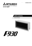
3.
Add the linker option to map the ROM section (PFRAM) address to RAM section address (RPFRAM) as seen
below.
4.
The linker is now setup to correctly allocate the appropriate Flash API code to RAM. Now we need to make sure
that the code gets copied from ROM to RAM after reset. If this is not done before a Flash API function is called
then the MCU will jump to uninitialized RAM. Two ways to copy this code to RAM are presented below.
The first way is to edit the dbsct.c. This file contains an array that specifies which RAM areas need to be initialized
after a reset. In dbsct.c add the initialization of this code for the RAM section as seen below in RED (note: don’t forget
to add the comma on the previous line)
-- FILE [dbsct.c] -#pragma section $DSEC
static const struct {
_UBYTE *rom_s; /* Initial address on ROM of initialization data section */
_UBYTE *rom_e; /* Final address on ROM of initialization data section */
_UBYTE *ram_s; /* Initial address on RAM of initialization data section */
}
DTBL[] = {
{ __sectop("D"), __secend("D"), __sectop("R") } ,
{ __sectop("PFRAM"), __secend("PFRAM"), __sectop("RPFRAM") }
};
Starting with v2.20 of the Simple Flash API for RX, there is now an API function that will copy the code to RAM. This
is the R_FlashCodeCopy() function. Just call this function before making any other Flash API calls. If using this
method the user will need to make sure and uncomment the macro for COPY_CODE_BY_API in
r_flash_api_rx_config.h. If using the dbsct.c method then the user can comment out this macro which will lead to the
R_FlashCodeCopy() function not being compiled.
R01AN0544EU0250 Rev.2.50
March 4, 2014
Page 9 of 33
RX600 & RX200 Series
Simple Flash API for RX
In e2 studio:
The same process of setting up the linker sections and mapping ROM to RAM needs to be done in e2 studio as well.
1. Add a new section titled ‘RPFRAM’ in a RAM area.
2. Add a new section titled ‘PFRAM’ in a ROM area.
3.
To make the linker map the PFRAM ROM section to the RPFRAM RAM section a new entry must be added to the
‘ROM to RAM mapped section’ table. This is done using the Linker >> Output section of the Tool Settings in e2
studio. Click the Add button and add an entry with the following text: PFRAM=RPFRAM.
4.
Follow the last step from the HEW instructions above to copy the Flash API to RAM.
R01AN0544EU0250 Rev.2.50
March 4, 2014
Page 10 of 33
RX600 & RX200 Series
2.14
Simple Flash API for RX
Using Non-Blocking Background Operations
When background operations (BGO) for ROM or data flash are enabled, API function calls will not block and will
return before the flash operation has finished. The user should take care in these instances that they do not try to access
the flash area that is being operated on until the operation has finished. If the area is accessed during an operation then
the FCU will go into an error state and the operation will fail.
The user will be alerted when a background flash operation has finished through a callback function. There are 3
callback functions that the Simple Flash API uses when an operation completes. The user should write these functions
in their application code. The 3 callback functions are:
•
void FlashEraseDone(void)
o
•
void FlashWriteDone(void)
o
•
This function is called when a data flash or ROM erase has completed
This function is called when a data flash or ROM write has completed
void FlashBlankCheckDone(uint8_t result)
o
This function is called when a data flash blank check has completed. The ‘result’ parameter will be
‘FLASH_BLANK’ in the event that the block was blank and ‘FLASH_NOT_BLANK’ in the event
that the block was not blank.
There is also a callback function in the event that a flash error has occurred.
•
void FlashError(void)
The Flash API will reset the FCU when an error is detected but this callback is included to alert the user that the flash
operation did not complete successfully.
R01AN0544EU0250 Rev.2.50
March 4, 2014
Page 11 of 33
RX600 & RX200 Series
Simple Flash API for RX
3. Usage Notes
3.1
Debugging within HEW
Using the E1, E20 and J-Link, you are allowed to debug while erasing and programming the on board flash memory
and data flash memory. Care should be taken to make sure that the flash block holding the user program is not erased
unless the user has some way of programming new code while executing in RAM.
You cannot use FDT or RFP programming software to view previously written data to flash memory when an ID code
has not been set. The reason for this is that RX600 and RX200 Series devices will automatically erase all flash memory
when entering boot mode as a built-in security feature. If an ID code is set then access to boot mode will be allowed
without first erasing flash memory. Please see the ‘ID Code Protection (Boot Mode)’ section of your MCU’s hardware
manual for more information.
If you attempt to disconnect and then re-connect to your system with HEW or e2 studio, the entire flash memory will be
erased upon re-connecting with default debugger settings. In order to preserve the flash values you will need to specify
which flash blocks you want to be overwritten, rather than erased. How to do this is shown below.
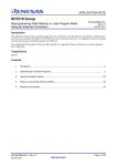
In HEW:
This is done in the ‘Configuration Properties’ window underneath the ‘Internal flash memory overwrite’ tab. Place a
check in the boxes next to the flash blocks you desire to be overwritten instead of being erased. A screenshot of the
window is below.
R01AN0544EU0250 Rev.2.50
March 4, 2014
Page 12 of 33
RX600 & RX200 Series
Simple Flash API for RX
In e2 studio:
This is done in the ‘Debug Configurations’ window which is accessed by selecting your project and clicking ‘Run >>
Debug Configurations’. Select your debug configuration and then select the ‘Debugger’ tab. Now click the ‘Debug Tool
Settings’ tab and click the box at the end of the row which contains ‘Internal Flash Memory Overwrite’.
Place a check in the boxes next to the flash blocks you desire to be overwritten instead of being erased and click OK.
R01AN0544EU0250 Rev.2.50
March 4, 2014
Page 13 of 33
RX600 & RX200 Series
3.2
Simple Flash API for RX
Viewing Programmed/Erased Flash Memory in HEW
Use of the Memory window inside HEW or e2 studio to view the flash memory contents after an erase or write will not
work under the default debugger settings. The reason for this is that the IDE will cache the flash memory contents when
the debug session starts and will not refresh the values after the program/erase command finishes. There is an option
when connecting though that specifies you are using CPU rewrite code and therefore to refresh the flash memory values.
This option will also inform the debugger to not cause ROM or data flash access violations when flash operations are
on-going. How to enable this feature is shown below.
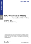
In HEW:
This option is in the ‘Configuration Properties’ window that will come up when connecting to the E1, E20, or J-Link.
Depending on which version of the debugger software is installed, you may see different options. The screenshots
below show the different screens that may be presented. First switch to the ‘System’ tab. If using an earlier version of
the debugger software (as shown below on the left) then check the box next to ‘Debug the program using the CPU rewrite mode’. If using a newer version of the software then you will likely see the screenshot on the right. In this case
check the boxes next to the memory areas you will be programming or erasing. If programming or erasing both, then
check both boxes as shown below. Now when using the memory window the current flash memory values will be
displayed.
R01AN0544EU0250 Rev.2.50
March 4, 2014
Page 14 of 33
RX600 & RX200 Series
Simple Flash API for RX
In e2 studio:
This is done in the ‘Debug Configurations’ window which is accessed by selecting your project and clicking ‘Run >>
Debug Configurations’. Select your debug configuration and then select the ‘Debugger’ tab. Now click the ‘Debug Tool
Settings’ tab and locate the ‘Program re-writes internal Program ROM’ and ‘Program re-writes internal Data Flash’
rows. Change the ‘Program re-writes internal Program ROM’ drop down to ‘Yes’ if your application will rewrite ROM.
Change the ‘Program re-writes internal Data Flash’ if your application will rewrite Data Flash.
3.3
ROM Area Boundaries
The RX600 and RX200 Series have some MCUs that have more than one ROM Area. For example, a RX63N with
2MB of ROM has 4 ROM Areas (Area 0, 1, 2, and 3). You are allowed to write over flash blocks that are inside the
same ROM Area, but not over ROM Area boundaries. If you do try to write over a boundary, then the R_FlashWrite()
function will return an error code before performing any write operations stating that this has occurred. In order to
write over a boundary, the user will have to take precautions to make sure and split the write up where the first write
programs up to the boundary and then the second write starts at the boundary.
Which ROM Area is currently selected for programming and erasure is controlled by the FENTRY bits located in the
FENTRYR register. The reason programming cannot go across the boundary is because only one of these bits can be
set at a time. Which bit is set is automatically taken care of when the user calls the R_FlashWrite() function.
3.4
Data Flash BGO Precautions
When using data flash BGO the User ROM, RAM, and external memory can still be accessed. This means that care
should only be taken to make sure that the data flash is not accessed during a data flash operation. This includes
interrupts that may access the data flash.
3.5
ROM BGO Precautions
When using ROM BGO external memory and RAM can still be accessed. Since most users will put their code in ROM,
extra care should be taken compared to performing BGO data flash operations. Since the API code will return before
the ROM operation has finished the code that calls the API function will need to be outside of the User ROM. Another
important issue to be aware of is the relocatable vector table. The vector table by default resides in the User ROM. If
an interrupt occurs during the ROM operation then ROM will be accessed to fetch the interrupt’s starting address and an
error will occur. To fix this situation the user will need to relocate the vector table and any interrupt service routines
that may occur outside of ROM. The user will also need to change the variable vector table’s pointer register (INTB).
R01AN0544EU0250 Rev.2.50
March 4, 2014
Page 15 of 33
RX600 & RX200 Series
3.6
Simple Flash API for RX
Interrupts
ROM or data flash areas cannot be accessed while a flash operation is on-going for that particular memory area. This
means that care will need to be taken when allowing interrupts to occur during flash operations. These precautions
apply whether the user is using BGO operations or not.
3.7
Configure for Only Data Flash Use
The Flash API can be configured to only enable data flash operations. This can be very beneficial for users who do not
need ROM operations because it saves code and RAM space. If ROM operations are disabled then the user does not
need to have any of the Flash API code in RAM. This means the user does not need to setup the RPFRAM and PFRAM
sections. In order to disable ROM operations the user should do the following:
1.
2.
3.
Comment out the FLASH_API_RX_CFG_ENABLE_ROM_PROGRAMMING macro in the file
r_flash_api_rx_config.h.
If you previously setup the RPFRAM and PFRAM sections then you can remove them. You can also remove the
ROM to RAM mapping that was previously setup. See Section 2.13 for more info.
You do not need to call the R_FlashCodeCopy() function if ROM operations are disabled. If you do call it, it will
just return without doing anything.
3.8
Erase Entire User Application Area (ROM)
There are multiple ways to erase the entire User Application Area. One way is to place the Flash API in the User Boot
Area. This area is usually used for bootloaders and can only be erased in Serial Boot Mode. Since the user’s application
cannot run in Boot Mode, the user does not have to worry about accidentally erasing the User Boot Area. When using
the User Boot Area the user will still need follow the steps to copy the appropriate Flash API functions to RAM. The
user will also need to move the relocatable vector table to either the User Boot Area or RAM if they are using ROM or
data flash BGO.
Another way to approach this is to copy everything to RAM and use RAM exclusively. When doing this the user will
need to modify the Flash API code to put the array that holds flash addresses in RAM instead of ROM. Follow these
steps to move the array to RAM:
1. Open up the header file for your MCU’s Group in the src/targets/ folder. For example, if you are using the RX62N
MCU then you would open the file src/targets/rx62n/r_flash_api_rx62n.h.
2. In the file find the g_flash_BlockAddresses[] array. There will be two declarations of the array. One that actually
defines the array’s contents and the other that declares it as an extern. Remove the const keyword from both
declarations. Removing the const keyword will move the array to RAM.
If using RAM only the user will also need to move the relocatable vector table to RAM if they are using ROM or data
flash BGO since these features use FCU interrupts.
3.9
Reading from Data Flash After Reset
After reset the user cannot read, write, or erase the data flash. In order to enable these operations the user will need to
call the R_FlashDataAreaAccess() function. See the API information page (Section 4.5) for more information.
3.10
Checking if a Data Flash Location is Blank (Erased)
Data flash locations on the RX cannot be checked for blank (i.e. erased) by comparing the read value to 0xFF. The
reason for this is that RX data flash cells actually have 2 cells per bit (compared to 1 cell per bit for ROM). This means
that there are 4 different states the bit can be in; though only 3 are used: undefined, 0, and 1. Erased data flash locations
on the RX have a value of undefined (not 0 or 1) and therefore the read bit value cannot be used to determine if the bit
is erased. When a data flash bit is programmed, one of the cells is always changed depending on whether a 0 or 1 is
being written. If the user wishes to know if a data flash location is erased then they should use the
R_FlashDataAreaBlankCheck() function (Section 4.6). This API function uses the Blank Check feature of the RX’s
Flash Control Unit (FCU) to determine if a data flash location has programmed data or not.
R01AN0544EU0250 Rev.2.50
March 4, 2014
Page 16 of 33
RX600 & RX200 Series
3.11
Simple Flash API for RX
Putting Flash API in User Boot Area
By default, the Renesas RX Toolchain will use 24 bits for the maximum distance that a branch instruction can jump to.
The options are 16, 24, or 32 bits. The smaller the chosen value, the smaller the compiled code will be. The reason for
this is that if you choose 16 or 24 bits then you are guaranteeing the Renesas RX Toolchain that the destination of all
branches will be within the range specified and therefore the compiler does not need to reserve 32 bits for branches.
With this guarantee the toolchain can save 1 byte per branch with 24 bit offsets or 2 bytes per branch with 16 bit offsets.
With regular applications, 24 bits will usually be fine. When using User Boot Mode with the Flash API though, 32 bit
branches are required. The reason for this is that the Flash API has to put some code in RAM when programming or
erasing ROM. Since the end of the User Boot Area is 0xFF800000 and the beginning of RAM is 0x00000000 this
means there is a distance of 0x800000. This appears to be within 24 bits, but branches can have positive or negative
offsets so the offset is a 2’s complement number and therefore the range is half in each direction. This means that calls
to Flash API routines in the User Boot Area cannot reach the functions in RAM with 24 bit branches. If the user does
not change this setting in the Renesas RX Toolchain then the user will get a ‘L2330 (E) Relocation size overflow’ error.
To set the Renesas RX Toolchain to use 32 bit branches, follow these steps:
In HEW:
1.
2.
3.
4.
5.
6.
Open up your project in HEW.
Go to Build >> RX Standard Toolchain.
Click the right arrow at the top-right of the ‘RX Standard Toolchain’ window until you can see the ‘CPU’ tab.
Click the ‘CPU’ tab.
Click the ‘Details…’ button.
In the window that comes up (‘CPU details’) choose ’32 bit’ for ‘Width of divergence of function’.
In e2 studio:
1.
2.
3.
4.
Right click on your project folder and select ‘Properties’.
Expand ‘C/C++ Build’ and click on ‘Settings’.
Click on the ‘Tool Settings’ tab and choose Compiler >> CPU >> Advanced.
Choose ’32 bit’ for ‘Width of divergence of function’..
R01AN0544EU0250 Rev.2.50
March 4, 2014
Page 17 of 33
RX600 & RX200 Series
3.12
Simple Flash API for RX
Execute from Data Flash
A common question is if the MCU can execute code from the data flash. The answer is yes, but performance will be
degraded. The reason for this is that the MCU can access ROM in a single cycle using the same clock that is used for
the CPU (ICLK) while the data flash is accessed using the FCLK (or PCLK on RX610 and RX62x MCUs). In many
cases the FCLK will be less than the ICLK which will lead to read delays. The real issue though is that the data flash
requires multiple cycles to be read no matter what frequency is used for the FCLK. For example, on the RX63N a ROM
read takes 1 cycle of ICLK while the data flash takes 6 cycles of the FCLK. Since the ICLK can operate at a maximum
of 100MHz while the FCLK has a maximum of 50MHz this means the user will potentially see a difference of
performance of around 12x.
Many users also ask if code can be executed from data flash while a ROM operation is on-going through the use of
BGO. This will not work since data flash cannot be accessed during a ROM operation. If this is attempted then an
access exception will occur.
3.13
Access Rules
The table below details what memory areas can be accessed while ROM and data flash operations are on-going.
Type of Operation
On-Going
RAM Access OK?
Data Flash Access
OK?
ROM Access OK?
External Memory
Access OK?
Data Flash
Yes
No
Yes
Yes
ROM
Yes
No
No
Yes
R01AN0544EU0250 Rev.2.50
March 4, 2014
Page 18 of 33
RX600 & RX200 Series
Simple Flash API for RX
4. API Functions
4.1
Summary
The following functions are included in this API:
Function
Description
R_FlashErase()
Erases an entire flash block.
R_FlashEraseRange()
Erases a range of addresses. Erases at least 1 flash block.
R_FlashWrite()
Write data to ROM or data flash.
R_FlashDataAreaAccess()
Enable read, write, erase access to data flash.
R_FlashDataAreaBlankCheck()
Check if a data flash address (or block) is erased.
R_FlashProgramLockBit()
Set lock bit for a ROM block so it cannot be erased or written.
R_FlashReadLockBit()
Read lock bit for a ROM block.
R_FLashSetLockBitProtection()
Enable or disable ROM lock bit protection.
R_FlashGetStatus()
Get the current status of flash operations.
R_FlashCodeCopy()
Copy Flash API code from ROM section to RAM.
R_FlashGetVersion()
Get the current version of this API.
R01AN0544EU0250 Rev.2.50
March 4, 2014
Page 19 of 33
RX600 & RX200 Series
4.2
Simple Flash API for RX
R_FlashErase
This function allows an entire flash block to be erased.
Format
uint8_t R_FlashErase(uint32_t block);
Parameters
block
Specifies the block to erase. This value is defined in the r_flash_api_rx_if.h file. The blocks are labeled
in the same fashion as they are in the device’s Hardware Manual. For example, on the RX610 the
block located at address 0xFFFFE000 is called Block 0 in the hardware manual therefore “BLOCK_0”
should be passed for this parameter.
Return Values
FLASH_SUCCESS:
FLASH_FAILURE:
FLASH_BUSY:
Operation successful (if BGO is enabled this means the operations was started
successfully)
Operation failed.
Other flash operation in progress, try again later
Properties
Prototyped in file “r_flash_api_rx_if.h”
Implemented in file “r_flash_api_rx.c”
Description
Erases a single block of flash memory. Starting with RX63x MCUs some RX MCUs now have much smaller
erase blocks for the data flash. For example, the RX630, RX631, and RX63N have 32 byte erase blocks.
This means that that for a 32KB data flash there are 1024 blocks. Instead of having a definition for each
block (e.g. BLOCK_DB0, BLOCK_DB1, …, BLOCK_DB1023) data flash blocks were grouped into 2KB
virtual blocks. Each virtual block therefore consists of 64 real data flash blocks. This was done to make it
easier on users to delete larger regions of data flash as has been done in the past. Users still have the
option of deleting with 32 byte granularity using the R_FlashEraseRange() function.
Reentrant
No, but is protected by lock to prevent errors from concurrent function calls.
Example
uint32_t loop;
uint8_t ret;
/* Search for record */
for (loop = 0; loop < NUM_BLOCKS_TO_ERASE; loop++)
{
/* Erase block */
ret = R_FlashErase(loop);
/* Check for errors. */
if (FLASH_SUCCESS != ret)
{
. . .
}
}
Special Notes:
Do not attempt to erase a flash block that you are currently executing from. If you are erasing a data flash
block then make sure you have enabled modifications of the data flash block by calling the
R_FlashDataAreaAccess() function.
R01AN0544EU0250 Rev.2.50
March 4, 2014
Page 20 of 33
RX600 & RX200 Series
4.3
Simple Flash API for RX
R_FlashEraseRange (Not Available on RX610, RX62x)
The function starts erasing data flash blocks at a given address and stops when the number of bytes to
erase has been reached.
Format
uint8_t R_FlashEraseRange(uint32_t start_addr, uint32_t bytes);
Parameters
start_addr
Specifies the address where the erase should begin. This must be on an erase boundary and the
address must be in the data flash area.
bytes
Specifies the number of bytes to erase. This must be a multiple of the data flash erase size. For
example, on the RX630 the data flash erase size is 32 bytes so 32, 64, 96, etc… could used for this
parameter.
Return Values
FLASH_SUCCESS:
Operation successful (if BGO is enabled this means the operations was
started successfully)
FLASH_FAILURE:
Operation failed.
FLASH_BUSY:
Other flash operation in progress, try again later
FLASH_ERROR_BYTES:
Number of bytes did not match erase size
FLASH_ERROR_ADDRESS:
Invalid address, this is only for data flash
FLASH_ERROR_ALIGNED:
Flash address not on erase boundary
FLASH_ERROR_OVERFLOW: Erase attempted to go past end of data flash
Properties
Prototyped in file “r_flash_api_rx_if.h”
Implemented in file “r_flash_api_rx.c”
Description
Erases at least 1 data flash block. This function was first introduced for RX63x MCUs that had significantly
smaller data flash erase sectors than previous RX600 MCUs. Instead of having the user deal with a large
number of data flash block #defines, this function allows the user to send in an address and how many bytes
they wish to erase.
Reentrant
No, but is protected by lock to prevent errors from concurrent function calls.
Example
uint8_t ret;
/* Erase 64 bytes. */
ret = R_FlashEraseRange(address, 64);
/* Check for errors. */
if (FLASH_SUCCESS != ret)
{
. . .
}
Special Notes:
•
•
•
This function is not available on RX610 or RX62x MCUs. The reason for this is that these MCUs
have larger data flash erase sectors and therefore can be erased using the R_FlashErase() function.
This function is only available for data flash blocks. Cannot be used on ROM blocks.
Make sure you have enabled modifications of the data flash block by calling the
R_FlashDataAreaAccess() function.
R01AN0544EU0250 Rev.2.50
March 4, 2014
Page 21 of 33
RX600 & RX200 Series
4.4
Simple Flash API for RX
R_FlashWrite
This function allows data to be written into flash.
Format
uint8_t R_FlashWrite(uint32_t
uint32_t
uint16_t
flash_addr,
buffer_addr,
bytes);
Parameters
flash_addr
This is a pointer to the Flash or Data Flash area to write. The address must be on a programming line
boundary. See Description below for important restrictions regarding this parameter.
buffer_addr
This is a pointer to the buffer containing the data to write to Flash.
bytes
The number of bytes contained in the buffer_addr buffer. This number must be a multiple of the
programming size for memory area you are writing to. See Special Notes below for important
restrictions regarding this parameter.
Return Values
FLASH_SUCCESS:
Operation successful (if BGO is enabled this means the operations was
started successfully)
FLASH_FAILURE:
Operation failed.
FLASH_BUSY:
Other flash operation in progress, try again later
FLASH_ERROR_ALIGNED:
Flash address was not on a programming boundary
FLASH_ERROR_BYTES:
Number of bytes provided was not a multiple of the programming size
FLASH_ERROR_ADDRESS:
Invalid address was input
FLASH_ERROR_BOUNDARY: (ROM) Cannot write across ROM Area Boundaries
FLASH_ERROR_OVERFLOW: Write attempted to go past end of ROM or DF
Properties
Prototyped in file “r_flash_api_rx_if.h”
Implemented in file “r_flash_api_rx.c”
Description
Writes data to flash memory.
When performing a write the user must make sure to start the write on a programming boundary and the
number of bytes to write must be a multiple of the programming size. The boundaries and programming
sizes differ depending on what MCU is being used and whether the ROM or data flash is being written to.
Programming boundaries start at the beginning of the flash area and then each boundary is a multiple of the
programming size. For example, if the programming line size is 256, then the flash address you pass must
have bits B0-B7 all be ‘0’.
Some RX MCUs have ROM Area boundaries (different than programming boundaries previously discussed)
that cannot be written over. If the user is writing over this location then they will need to make sure to split up
the writes such that the first write will program up to the boundary, and the second write will start at the
boundary. If the user tries to write over this boundary the function will return an error before doing any
programming operations. The user can see the boundaries for their device by looking at the ROM_AREA_#
definitions for their device in r_flash_api_rx_private.h.
Reentrant
No, but is protected by lock to prevent errors from concurrent function calls.
R01AN0544EU0250 Rev.2.50
March 4, 2014
Page 22 of 33
RX600 & RX200 Series
Simple Flash API for RX
Example
uint8_t ret;
uint8_t write_buffer[PROGRAM_SIZE] = “Hello World...”;
/* Write data to internal memory. */
ret = R_FlashWrite(address, (uint32_t)write_buffer, PROGRAM_SIZE);
/* Check for errors. */
if (FLASH_SUCCESS != ret)
{
. . .
}
Special Notes:
The programming sizes for different RX MCUs are shown in the table below.
ROM
Programming Line Size
Data Flash
Programming Line Size
RX61x & RX62x Groups
256 bytes
8 or 128 bytes
RX63x Groups
128 bytes
2 bytes
RX210 Group
2, 8, or 128 bytes
2 or 8 bytes
MCU
If you are writing a data flash block then make sure you have enabled modifications of the data flash block by
calling the R_FlashDataAreaAccess() function.
R01AN0544EU0250 Rev.2.50
March 4, 2014
Page 23 of 33
RX600 & RX200 Series
4.5
Simple Flash API for RX
R_FlashDataAreaAccess
This function allows Data Flash areas to be accessed or modified. The data flash cannot be read, written,
or erased before calling this function.
Format
void R_FlashDataAreaAccess(uint16_t read_en_mask,
uint16_t write_en_mask);
Parameters
read_en_mask
This is a bitmapped value where bits are used to determine which Data blocks should be able to be
read by the MCU. A ‘0’ indicates the block cannot be accessed and a ‘1’ indicates it can. Bits 0-3
represent Data Blocks 0-3 respectively.
write_en_mask
This is a bitmapped value where bits are used to determine which Data blocks should be able to be
modified (Erase/Write) by the Flash Control Unit (FCU). A ‘0’ indicates the block cannot be modified
and a ‘1’ indicates it can. Bits 0-3 represent Data Blocks 0-3 respectively.
Return Values
None.
Properties
Prototyped in file “r_flash_api_rx_if.h”
Implemented in file “r_flash_api_rx.c”
Description
After reset, the data flash area is not readable by the MCU. It is also not enabled for reprogramming. This
function is used to select what blocks you would like to be read or modifiable. You only have to set this
function once at the beginning of your application.
Reentrant
No, but this function should only need to be called once after reset.
Example
/* Enable reading, writing, and erasing of all data flash blocks. */
R_FlashDataAreaAccess(0xFFFF, 0xFFFF);
Special Notes:
None.
R01AN0544EU0250 Rev.2.50
March 4, 2014
Page 24 of 33
RX600 & RX200 Series
4.6
Simple Flash API for RX
R_FlashDataAreaBlankCheck
This function is used to determine if an area in the Data Flash area is blank or not, since this cannot be
determined by simply reading the memory location. This function is required because the user cannot
read data flash locations and check they are blank by comparing them to 0xFF.
Format
uint8_t R_FlashDataAreaBlankCheck(uint32_t address, uint8_t size);
Parameters
address
The address of the area to blank check.
If the parameter 'size'=='BLANK_CHECK_SMALLEST', this should be set to an appropriate address
boundary based upon the smallest blank check size. The smallest blank check size is the same as the
smallest program size for the data flash.
If the parameter 'size' is specified as 'BLANK_CHECK_ENTIRE_BLOCK' this should be set to a
defined Data Block Number ('BLOCK_DB0', 'BLOCK_DB1', 'BLOCK_DB2' or 'BLOCK_DB3') or an
address in the data flash block. Either option will work.
size
This specifies if you are checking an entire flash block or a smaller memory area. The size of the
smaller memory area will match the smallest programming size of the data flash for the MCU being
used. You must set this to either 'BLANK_CHECK_SMALLEST' or 'BLANK_CHECK_ENTIRE_BLOCK'.
Return Values
FLASH_BLANK:
FLASH_NOT_BLANK:
FLASH_FAILURE:
FLASH_BUSY:
FLASH_ERROR_ADDRESS:
FLASH_ERROR_BYTES:
FLASH_ERROR_ALIGNED:
(Small memory area check or non-BGO) Address was blank.
(Entire Block & BGO) Blank check operation started.
Address was not blank
Operation Failed
Another flash operation is in progress
Invalid address was input
Incorrect 'size' was submitted
Address not on programming boundary (only required when ‘size’ !=
BLANK_CHECK_ENTIRE_BLOCK)
Properties
Prototyped in file “r_flash_api_rx_if.h”
Implemented in file “r_flash_api_rx.c”
Description
Before you can write to any flash area in an MCU, the area must already be blank. Since the memory
locations in RX600 and RX200 Series Data Flash areas are not represented by a defined ‘blank’ value of
0xFF like they are in the User Program area, an additional function is needed to test a section of flash to
determine if it is blank.
RX600 and RX200 Series devices have two methods for checking for blank areas; one checks a smaller
area and the other a larger area. The number of bytes checked by the smaller method is same as the
programming size for the data flash (i.e. 8 bytes on RX610 and RX62x, 2 bytes on RX63x). The larger check
performs the blank check on the entire Data Flash block at once. This function does not have to be called for
each section prior to programming. It is simply here to assist in application programming.
Reentrant
No, but is protected by lock to prevent errors from concurrent function calls.
R01AN0544EU0250 Rev.2.50
March 4, 2014
Page 25 of 33
RX600 & RX200 Series
Simple Flash API for RX
Example
uint8_t ret;
/* Blank check an entire data flash block. */
ret = R_FlashDataAreaBlankCheck(address, BLANK_CHECK_ENTIRE_BLOCK);
/* Check result. */
if (FLASH_NOT_BLANK == ret)
{
/* Block is not blank. */
. . .
}
else if (FLASH_BLANK == ret)
{
/* Block is blank. */
. . .
}
Special Notes:
The blank check sizes for different RX MCUs are shown in the table below.
MCU
Blank Check Sizes
RX610
8 bytes or Entire Block (8KB)
RX62x
8 bytes or Entire Block (2KB)
RX63x
2 bytes or Entire Block (2KB)
RX210
2 bytes or Entire Block (2KB)
Earlier versions of this API had the option to use BLANK_CHECK_2_BYTE or BLANK_CHECK_8_BYTE
depending on which MCU was being used. The use of these macros has been deprecated in favor of use of
the BLANK_CHECK_SMALLEST macro. Use of BLANK_CHECK_2_BYTE or BLANK_CHECK_8_BYTE will
still work with no issues.
R01AN0544EU0250 Rev.2.50
March 4, 2014
Page 26 of 33
RX600 & RX200 Series
4.7
Simple Flash API for RX
R_FlashProgramLockBit
Sets the lock bit for a flash block.
Format
uint8_t R_FlashProgramLockBit(uint32_t block);
Parameters
block
The ROM erasure block that will have its lock bit set.
Return Values
FLASH_SUCCESS:
FLASH_FAILURE:
FLASH_BUSY:
FLASH_ERROR_ADDRESS:
Operation successful, lock bit set.
Operation failed.
Other flash operation in progress, try again later
Invalid block was input.
Properties
Prototyped in file “r_flash_api_rx_if.h”
Implemented in file “r_flash_api_rx.c”
Description
Each block of ROM has a lock bit associated with it. If lock bit protection is enabled and the lock bit is set for
a given block then that block cannot be programmed or erased. If an attempt to erase or program the block
is made, the operation will be ignored. This function will set the lock bit for the selected flash block. Whether
lock bit protection is enabled or not is controlled by the API function R_FlashSetLockBitProtection().
Reentrant
No, but is protected by lock to prevent errors from concurrent function calls.
Example
uint8_t ret;
/* Enable lock bit protection (this is default out of reset) */
ret = R_FlashSetLockBitProtection(true);
/* Check for errors. */
if (FLASH_SUCCESS != ret)
{
. . .
}
/* Program lock bits */
ret = R_FlashProgramLockBit(flash_block);
/* Check for errors. */
if (FLASH_SUCCESS != ret)
{
. . .
}
Special Notes:
•
•
Lock bits for a flash block are cleared by erasing the flash block with lock bit protection disabled.
This function is not available for use when the FLASH_API_RX_CFG_IGNORE_LOCK_BITS macro
is defined in r_flash_api_rx_config.h.
R01AN0544EU0250 Rev.2.50
March 4, 2014
Page 27 of 33
RX600 & RX200 Series
4.8
Simple Flash API for RX
R_FlashReadLockBit
Reads the lock bit for a flash block.
Format
uint8_t R_FlashReadLockBit(uint32_t block);
Parameters
block
The ROM erasure block that will have its lock bit read.
Return Values
FLASH_LOCK_BIT_SET:
Lock bit is set
FLASH_LOCK_BIT_NOT_SET: Lock bit is not set
FLASH_FAILURE:
Operation Failed
FLASH_BUSY:
Another flash operation is in progress
FLASH_ERROR_ADDRESS: Invalid block was input.
Properties
Prototyped in file “r_flash_api_rx_if.h”
Implemented in file “r_flash_api_rx.c”
Description
Each block of ROM has a lock bit associated with it. If lock bit protection is enabled and the lock bit is set for
a given block then that block cannot be programmed or erased. If an attempt to erase or program the block
is made, the operation will be ignored. This function will return whether a flash block has its lock bit set or
not. Whether lock bit protection is enabled or not is controlled by the API function
R_FlashSetLockBitProtection().
Reentrant
No, but is protected by lock to prevent errors from concurrent function calls.
Example
uint8_t ret;
/* Program lock bits */
ret = R_FlashReadLockBit(flash_block);
/* Check result. */
if (FLASH_LOCK_BIT_SET == ret)
{
/* Lock bit is set for this block. */
. . .
}
else if (FLASH_LOCK_BIT_NOT_SET == ret)
{
/* Lock bit was not set for this block. */
. . .
}
Special Notes:
•
•
Lock bits for a flash block are cleared by erasing the flash block with lock bit protection disabled.
This function is not available for use when the FLASH_API_RX_CFG_IGNORE_LOCK_BITS macro
is defined in r_flash_api_rx_config.h.
R01AN0544EU0250 Rev.2.50
March 4, 2014
Page 28 of 33
RX600 & RX200 Series
4.9
Simple Flash API for RX
R_FlashSetLockBitProtection
Enables or disables lock bit protection.
Format
uint8_t R_FlashSetLockBitProtection(uint32_t lock_bit);
Parameters
lock_bit
Boolean value that determines whether to enable or disable lock bit protection. If set to ‘true’ then lock
bit protection will be enabled. If set to ‘false’ then lock bit protection will be disabled.
Return Values
FLASH_SUCCESS:
FLASH_BUSY:
Operation was successful
Flash is busy with another operation
Properties
Prototyped in file “r_flash_api_rx_if.h”
Implemented in file “r_flash_api_rx.c”
Description
Each block of ROM has a lock bit associated with it. If lock bit protection is enabled and the lock bit is set for
a given block then that block cannot be programmed or erased. If an attempt to erase or program the block
is made, the operation will be ignored. This function controls whether lock bit protection is enabled. If
disabled then all flash blocks are eligible for programming and erasure regardless of whether their lock bit is
set or not.
Reentrant
No, but is protected by lock to prevent errors from concurrent function calls.
Example
uint8_t ret;
/* Enable lock bit protection (this is default out of reset) */
ret = R_FlashSetLockBitProtection(true);
/* Check for errors. */
if (FLASH_SUCCESS != ret)
{
. . .
}
Special Notes:
•
•
Lock bits for a flash block are cleared by erasing the flash block with lock bit protection disabled.
This function is not available for use when the FLASH_API_RX_CFG_IGNORE_LOCK_BITS macro
is defined in r_flash_api_rx_config.h.
R01AN0544EU0250 Rev.2.50
March 4, 2014
Page 29 of 33
RX600 & RX200 Series
4.10
Simple Flash API for RX
R_FlashGetStatus
Returns the current state of the flash.
Format
uint8_t R_FlashGetStatus(void);
Parameters
None.
Return Values
FLASH_SUCCESS:
FLASH_BUSY:
Flash is ready to use
Flash is busy with another operation
Properties
Prototyped in file “r_flash_api_rx_if.h”
Implemented in file “r_flash_api_rx.c”
Description
This function will return the current state of the flash. If BGO operations are used then this function call can
be used to poll for detecting when the last flash operation has finished.
Reentrant
Yes.
Example
uint8_t ret;
/* Blank check an entire data flash block. */
ret = R_FlashDataAreaBlankCheck(address, BLANK_CHECK_ENTIRE_BLOCK);
while( R_FlashGetStatus() == FLASH_BUSY )
{
/* Wait for previous operation to finish. You could also stall this task
and do some real work. */
}
Special Notes:
None.
R01AN0544EU0250 Rev.2.50
March 4, 2014
Page 30 of 33
RX600 & RX200 Series
4.11
Simple Flash API for RX
R_FlashCodeCopy
Copies Flash API code from ROM to RAM.
Format
void R_FlashCodeCopy(void);
Parameters
None.
Return Values
None.
Properties
Prototyped in file “r_flash_api_rx_if.h”
Implemented in file “r_flash_api_rx.c”
Description
When programming or erasing ROM the Flash API code cannot reside in ROM. This function will transfer the
code from ROM to RAM.
Reentrant
Yes.
Example
/* Transfer Flash API code to RAM so that we can program/erase ROM. */
R_FlashCodeCopy();
/* Flash API can now program/erase ROM. */
Special Notes:
•
•
•
If you are only programming/erasing data flash (not ROM) then all Flash API code will reside in ROM
and this function will not need to be called.
If using the dbsct.c method described in Section 2.13 then this function does not need to be run.
If you are programming/erasing ROM and not using the dbsct.c method then this function must be
run before any other Flash API functions are called. If this function is not called first then other Flash
API functions will jump to uninitialized RAM.
R01AN0544EU0250 Rev.2.50
March 4, 2014
Page 31 of 33
RX600 & RX200 Series
4.12
Simple Flash API for RX
R_FlashGetVersion
Returns the current version of the Flash API.
Format
uint32_t R_FlashGetVersion(void);
Parameters
None.
Return Values
Version of Flash API.
Properties
Prototyped in file “r_flash_api_rx_if.h”
Implemented in file “r_flash_api_rx.c”
Description
This function will return the version of the currently installed Flash API. The version number is encoded
where the top 2 bytes are the major version number and the bottom 2 bytes are the minor version number.
For example, Version 4.25 would be returned as 0x00040019.
Reentrant
Yes.
Example
uint32_t cur_version;
/* Get version of installed Flash API. */
cur_version = R_FlashGetVersion();
/* Check to make sure version is new enough for this application’s use. */
if (MIN_VERSION > cur_version)
{
/* This Flash API version is not new enough and does not have XXX feature
that is needed by this application. Alert user. */
....
}
Special Notes:
•
This function is specified to be an inline function in r_flash_api_rx.c.
R01AN0544EU0250 Rev.2.50
March 4, 2014
Page 32 of 33
RX600 & RX200 Series
Simple Flash API for RX
Website and Support
Renesas Electronics Website
http://www.renesas.com/
Inquiries
http://www.renesas.com/inquiry
All trademarks and registered trademarks are the property of their respective owners.
R01AN0544EU0250 Rev.2.50
March 4, 2014
Page 33 of 33
Revision Record
Rev.
1.00
1.20
Date
Jan.27.10
Feb.11.10
1.30
1.40
1.41
1.43
2.00
Mar.05.10
May.26.10
Jun.11.10
Feb.18.11
Apr.27.11
2.10
Jul.11.11
2.20
Dec.01.11
2.30
Sep.12.12
2.40
Dec.12.12
2.50
Mar.04.14
Description
Page
Summary
—
First edition issued
—
Made minor text revisions and added section on disabling
interrupts.
—
Made fixes based on recommendations from RTE
—
Revised to include support for the RX62x Group
—
Fixed some typographical errors
12
Updated blank check function argument description
—
API now includes support for BGO, flash to flash transfers, and
lock bit protection.
—
Added support for RX630, RX631, and RX63N devices.
Removed ‘DATA_FLASH_OPERATION_PIPL’ and
‘ROM_OPERATION_PIPL’ definitions and added section that
talks about why this was done. Added R_FlashEraseRange()
function to API. Rewrote section on ROM area boundaries
(used to be Section 3.4) to apply to RX610 and RX63x
devices.
—
Moved document over to new template. Restructured existing
data and added new information about using r_bsp package.
Added the R_FlashCodeCopy() function to the API.
—
Added R_FlashGetVersion() function to the API. Removed
config macro for not using r_bsp; the code now recognizes this
automatically. Added ‘Configure for Only Data Flash Use’,
‘Erased Entire User Application Area’, ‘Reading from Data
Flash After Reset’, ‘Checking if a Data Flash Location is Blank’,
and ‘Putting Flash API in User Boot Area’ sections. Added
blank check size table in R_FlashDataAreaBlankCheck
section.
—
Added support for RX210, RX62G, and RX63T MCUs. Since
RX200 Series devices are now supported the name was
changed from Simple Flash API for RX600 to Simple Flash API
for RX. Expanded ‘Checking if a Data Flash Location is Blank
(Erased)’ section. Added note on first page about where to find
info about why erased data flash locations are not read as
0xFF since this question comes up often. Added API list to
beginning of API Functions section. Added Demo Projects
section.
—
Added support for RX21A and RX220. For all instructions that
2
referenced HEW, the equivalent steps are now provided for e
studio. Added ‘Execute from Data Flash’ subsection. Added
‘Access Rules’ subsection. Added Related Documents to cover
page. Added ‘Memory Requirements’ subsection. Removed
‘Bootloader Implementations’ section. Revised
‘R_FlashDataAreaBlankCheck’ subsection with use of new
‘BLANK_CHECK_SMALLEST’ macro. Use of
‘BLANK_CHECK_2_BYTE’ & ‘BLANK_CHECK_8_BYTE’ has
been deprecated. Removed ‘Demo’ section.
A-1
General Precautions in the Handling of MPU/MCU Products
The following usage notes are applicable to all MPU/MCU products from Renesas. For detailed usage notes on the
products covered by this document, refer to the relevant sections of the document as well as any technical updates that
have been issued for the products.
1. Handling of Unused Pins
Handle unused pins in accordance with the directions given under Handling of Unused Pins in the
manual.
The input pins of CMOS products are generally in the high-impedance state. In operation with an
unused pin in the open-circuit state, extra electromagnetic noise is induced in the vicinity of LSI, an
associated shoot-through current flows internally, and malfunctions occur due to the false
recognition of the pin state as an input signal become possible. Unused pins should be handled as
described under Handling of Unused Pins in the manual.
2. Processing at Power-on
The state of the product is undefined at the moment when power is supplied.
The states of internal circuits in the LSI are indeterminate and the states of register settings and
pins are undefined at the moment when power is supplied.
In a finished product where the reset signal is applied to the external reset pin, the states of pins
are not guaranteed from the moment when power is supplied until the reset process is completed.
In a similar way, the states of pins in a product that is reset by an on-chip power-on reset function
are not guaranteed from the moment when power is supplied until the power reaches the level at
which resetting has been specified.
3. Prohibition of Access to Reserved Addresses
Access to reserved addresses is prohibited.
The reserved addresses are provided for the possible future expansion of functions. Do not access
these addresses; the correct operation of LSI is not guaranteed if they are accessed.
4. Clock Signals
After applying a reset, only release the reset line after the operating clock signal has become stable.
When switching the clock signal during program execution, wait until the target clock signal has
stabilized.
When the clock signal is generated with an external resonator (or from an external oscillator)
during a reset, ensure that the reset line is only released after full stabilization of the clock signal.
Moreover, when switching to a clock signal produced with an external resonator (or by an external
oscillator) while program execution is in progress, wait until the target clock signal is stable.
5. Differences between Products
Before changing from one product to another, i.e. to a product with a different part number, confirm
that the change will not lead to problems.
The characteristics of an MPU or MCU in the same group but having a different part number may
differ in terms of the internal memory capacity, layout pattern, and other factors, which can affect
the ranges of electrical characteristics, such as characteristic values, operating margins, immunity
to noise, and amount of radiated noise. When changing to a product with a different part number,
implement a system-evaluation test for the given product.
Notice
1.
Descriptions of circuits, software and other related information in this document are provided only to illustrate the operation of semiconductor products and application examples. You are fully responsible for
the incorporation of these circuits, software, and information in the design of your equipment. Renesas Electronics assumes no responsibility for any losses incurred by you or third parties arising from the
use of these circuits, software, or information.
2.
Renesas Electronics has used reasonable care in preparing the information included in this document, but Renesas Electronics does not warrant that such information is error free. Renesas Electronics
assumes no liability whatsoever for any damages incurred by you resulting from errors in or omissions from the information included herein.
3.
Renesas Electronics does not assume any liability for infringement of patents, copyrights, or other intellectual property rights of third parties by or arising from the use of Renesas Electronics products or
technical information described in this document. No license, express, implied or otherwise, is granted hereby under any patents, copyrights or other intellectual property rights of Renesas Electronics or
others.
4.
You should not alter, modify, copy, or otherwise misappropriate any Renesas Electronics product, whether in whole or in part. Renesas Electronics assumes no responsibility for any losses incurred by you or
5.
Renesas Electronics products are classified according to the following two quality grades: "Standard" and "High Quality". The recommended applications for each Renesas Electronics product depends on
third parties arising from such alteration, modification, copy or otherwise misappropriation of Renesas Electronics product.
the product's quality grade, as indicated below.
"Standard": Computers; office equipment; communications equipment; test and measurement equipment; audio and visual equipment; home electronic appliances; machine tools; personal electronic
equipment; and industrial robots etc.
"High Quality": Transportation equipment (automobiles, trains, ships, etc.); traffic control systems; anti-disaster systems; anti-crime systems; and safety equipment etc.
Renesas Electronics products are neither intended nor authorized for use in products or systems that may pose a direct threat to human life or bodily injury (artificial life support devices or systems, surgical
implantations etc.), or may cause serious property damages (nuclear reactor control systems, military equipment etc.). You must check the quality grade of each Renesas Electronics product before using it
in a particular application. You may not use any Renesas Electronics product for any application for which it is not intended. Renesas Electronics shall not be in any way liable for any damages or losses
incurred by you or third parties arising from the use of any Renesas Electronics product for which the product is not intended by Renesas Electronics.
6.
You should use the Renesas Electronics products described in this document within the range specified by Renesas Electronics, especially with respect to the maximum rating, operating supply voltage
range, movement power voltage range, heat radiation characteristics, installation and other product characteristics. Renesas Electronics shall have no liability for malfunctions or damages arising out of the
use of Renesas Electronics products beyond such specified ranges.
7.
Although Renesas Electronics endeavors to improve the quality and reliability of its products, semiconductor products have specific characteristics such as the occurrence of failure at a certain rate and
malfunctions under certain use conditions. Further, Renesas Electronics products are not subject to radiation resistance design. Please be sure to implement safety measures to guard them against the
possibility of physical injury, and injury or damage caused by fire in the event of the failure of a Renesas Electronics product, such as safety design for hardware and software including but not limited to
redundancy, fire control and malfunction prevention, appropriate treatment for aging degradation or any other appropriate measures. Because the evaluation of microcomputer software alone is very difficult,
please evaluate the safety of the final products or systems manufactured by you.
8.
Please contact a Renesas Electronics sales office for details as to environmental matters such as the environmental compatibility of each Renesas Electronics product. Please use Renesas Electronics
products in compliance with all applicable laws and regulations that regulate the inclusion or use of controlled substances, including without limitation, the EU RoHS Directive. Renesas Electronics assumes
no liability for damages or losses occurring as a result of your noncompliance with applicable laws and regulations.
9.
Renesas Electronics products and technology may not be used for or incorporated into any products or systems whose manufacture, use, or sale is prohibited under any applicable domestic or foreign laws or
regulations. You should not use Renesas Electronics products or technology described in this document for any purpose relating to military applications or use by the military, including but not limited to the
development of weapons of mass destruction. When exporting the Renesas Electronics products or technology described in this document, you should comply with the applicable export control laws and
regulations and follow the procedures required by such laws and regulations.
10. It is the responsibility of the buyer or distributor of Renesas Electronics products, who distributes, disposes of, or otherwise places the product with a third party, to notify such third party in advance of the
contents and conditions set forth in this document, Renesas Electronics assumes no responsibility for any losses incurred by you or third parties as a result of unauthorized use of Renesas Electronics
products.
11. This document may not be reproduced or duplicated in any form, in whole or in part, without prior written consent of Renesas Electronics.
12. Please contact a Renesas Electronics sales office if you have any questions regarding the information contained in this document or Renesas Electronics products, or if you have any other inquiries.
(Note 1)
"Renesas Electronics" as used in this document means Renesas Electronics Corporation and also includes its majority-owned subsidiaries.
(Note 2)
"Renesas Electronics product(s)" means any product developed or manufactured by or for Renesas Electronics.
SALES OFFICES
http://www.renesas.com
Refer to "http://www.renesas.com/" for the latest and detailed information.
Renesas Electronics America Inc.
2801 Scott Boulevard Santa Clara, CA 95050-2549, U.S.A.
Tel: +1-408-588-6000, Fax: +1-408-588-6130
Renesas Electronics Canada Limited
1101 Nicholson Road, Newmarket, Ontario L3Y 9C3, Canada
Tel: +1-905-898-5441, Fax: +1-905-898-3220
Renesas Electronics Europe Limited
Dukes Meadow, Millboard Road, Bourne End, Buckinghamshire, SL8 5FH, U.K
Tel: +44-1628-585-100, Fax: +44-1628-585-900
Renesas Electronics Europe GmbH
Arcadiastrasse 10, 40472 Düsseldorf, Germany
Tel: +49-211-6503-0, Fax: +49-211-6503-1327
Renesas Electronics (China) Co., Ltd.
Room 1709, Quantum Plaza, No.27 ZhiChunLu Haidian District, Beijing 100191, P.R.China
Tel: +86-10-8235-1155, Fax: +86-10-8235-7679
Renesas Electronics (Shanghai) Co., Ltd.
Unit 301, Tower A, Central Towers, 555 Langao Road, Putuo District, Shanghai, P. R. China 200333
Tel: +86-21-2226-0888, Fax: +86-21-2226-0999
Renesas Electronics Hong Kong Limited
Unit 1601-1613, 16/F., Tower 2, Grand Century Place, 193 Prince Edward Road West, Mongkok, Kowloon, Hong Kong
Tel: +852-2265-6688, Fax: +852 2886-9022/9044
Renesas Electronics Taiwan Co., Ltd.
13F, No. 363, Fu Shing North Road, Taipei 10543, Taiwan
Tel: +886-2-8175-9600, Fax: +886 2-8175-9670
Renesas Electronics Singapore Pte. Ltd.
80 Bendemeer Road, Unit #06-02 Hyflux Innovation Centre, Singapore 339949
Tel: +65-6213-0200, Fax: +65-6213-0300
Renesas Electronics Malaysia Sdn.Bhd.
Unit 906, Block B, Menara Amcorp, Amcorp Trade Centre, No. 18, Jln Persiaran Barat, 46050 Petaling Jaya, Selangor Darul Ehsan, Malaysia
Tel: +60-3-7955-9390, Fax: +60-3-7955-9510
Renesas Electronics Korea Co., Ltd.
12F., 234 Teheran-ro, Gangnam-Ku, Seoul, 135-920, Korea
Tel: +82-2-558-3737, Fax: +82-2-558-5141
© 2014 Renesas Electronics Corporation. All rights reserved.
Colophon 4.0