1
APPLICATION NOTE
Firmware Integration Technology
User's Manual
R01AN1833EU0100
Rev.1.00
Nov 15, 2013
Introduction
Firmware Integration Technology (FIT) is a global set of Renesas standards enabling creation of quality, easy-to-use,
inter-operable firmware. This document will give specific information on what FIT is, how it works, and how to use
FIT code with your own application code.
Target Device
RX Family
When using this application note with other Renesas MCUs, careful evaluation is recommended after making
modifications to comply with the alternate MCU.
Related Documents
•
Board Support Package Using Firmware Integration Technology Module (R01AN1685EU0230)
•
Adding Firmware Integration Technology Modules to Projects (R01AN1723EU0100)
Contents
1.
Overview ........................................................................................................................................... 2
2.
Board Support Package .................................................................................................................... 4
3.
Module File Structure ........................................................................................................................ 5
4.
Using FIT Modules ............................................................................................................................ 7
5.
Tutorial .............................................................................................................................................. 9
6.
Frequently Asked Questions ........................................................................................................... 14
Website and Support ............................................................................................................................... 15
R01AN1833EU0100 Rev.1.00
Nov 15, 2013
Page 1 of 15
Firmware Integration Technology
User's Manual
1. Overview
1.1
Terminology
The following terms will be used throughout the rest of this document.
Term
Meaning
Module
The core unit of FIT. Modules can be peripheral drivers, purely software (i.e.
middleware), or anything in between. Each Module consists of a folder with source
code, documentation, and anything else that the user needs to use the code effectively.
Modules are independent units, but they may depend on other FIT Modules. FIT
Modules are designed to work together out-of-the-box. Example FIT Modules could be:
• UART driver
• MMC protocol code (relies on separate SPI driver Module)
• Low power mode controller
• MP3 decoder/encoder software
Applications can be built by combining multiple FIT modules with user application
code to provide the users with the features they need.
Platform
The user’s development board. Used interchangeably with ‘board’.
BSP
Short for Board Support Package. BSP’s usually have source files related to a specific
board.
r_bsp
Renesas provided Board Support Package FIT Module. Provides a common foundation
of code, for a variety of boards and MCUs, upon which FIT Modules and user
application code can be built. See Section 2 for more information.
Callback Function
This term refers to a function that is called when an event occurs. For example, the bus
error interrupt handler is implemented in the r_bsp. The user will likely want to know
when a bus error occurs. To alert the user, a callback function can be supplied to the
r_bsp. When a bus error occurs the r_bsp will jump to the provided callback function
and the user can handle the error. Most callbacks in FIT Modules occur from within
Interrupt Service Routines (ISRs), which means other interrupts in the system may be
delayed while processing the callback. Because of this, user created callback functions
should be kept as short as possible.
1.2
What is FIT?
Firmware Integration Technology is an agreed upon set of rules that all Renesas developers follow when writing FIT
code. Users may follow the FIT rules if they want, but there is no requirement for them to apply any of the FIT rules to
their own code. Key items that are addressed by the FIT rules are:
•
•
•
•
•
•
•
1.3
Easy insertion into user’s existing project
Integrating multiple modules
Simple, one file configuration
Common documentation practices
Common file and directory structure
Strong foundation to build code on top of
Mixture of compile-time and run-time configuration options
Why is FIT needed?
Microcontrollers continue to evolve and become more complex. In order to be able to use all the new and advanced
peripherals that are available, the software needed to evolve as well. FIT fills this need by offering advanced software
while exposing a simple API to the user.
R01AN1833EU0100 Rev.1.00
Nov 15, 2013
Page 2 of 15
Firmware Integration Technology
1.4
User's Manual
What does a FIT project look like?
A user's project that uses FIT will typically have 3 parts.
1.
2.
3.
User Application Code:
Includes all code written by user such as application code and custom drivers.
FIT Modules:
Multiple FIT modules; each of which provides its own individual features and functions. Examples
include peripheral drivers and software middleware. FIT Modules can be dependent upon other FIT
modules as shown in the example.
FIT Board Support Package:
Board support package for the user's custom board. The r_bsp is technically a FIT module too, but it
is shown separately here because it is the lowest layer that all other FIT modules depend on.
R01AN1833EU0100 Rev.1.00
Nov 15, 2013
Page 3 of 15
Firmware Integration Technology
User's Manual
2. Board Support Package
The foundation of any project that uses FIT modules is the Renesas Board Support Package, abbreviated as r_bsp. The
r_bsp provides a common starting point for all projects, and is a baseline requirement for all FIT modules. It is
responsible for getting the MCU from reset to the user application's main() function. The r_bsp contains startup code
for a specific platform, such as early pin initialization and clock setup, and a base set of common MCU-specific
services such as setting the global interrupt level, I/O register definitions, and resource locking primitives. Many MCUs
are supported, and the r_bsp is meant to be modified for use with the user's custom board. Choosing a particular board
from the r_bsp is done through the platform.h header file. Configuration of the r_bsp is completed through a single
header file r_bsp_config.h.
2.1
Features
Most Renesas MCUs can be configured in many ways on reset. Knowing all of the configuration options and how to set
them can be a daunting task; especially for a new user. The r_bsp makes this easier by supplying the user with a known
good default configuration that can easily be modified. Typical features of the r_bsp include:
1.
2.
3.
4.
5.
6.
7.
Clock setup and configuration
Stack initialization
Setup of MCU exceptions with callbacks for events
Support for security features (e.g. flash access protection)
Provides API functions for common CPU tasks
Makes information about the current MCU and board available to FIT modules and the user
Many more...
For much more information on the r_bsp, including a complete list of the features, how to add it to your project, and
how to make your own custom BSP, please reference the ‘Board Support Package FIT Module’ application note
(R01AN1685EU).
2.2
Using the r_bsp in Application Code
After the r_bsp FIT Module has been added to a project, all of its API functions, types, and macros can be accessed
from your application code by including the platform.h file. platform.h must always be included before any other FIT
Modules. For example, if your source file uses the r_gpio_rx, r_sci_async_rx, and r_s12ad_rx Modules then its
includes would look like this:
/* platform.h must always be included first. */
#include "platform.h"
/* The order of these FIT Module includes does not matter. */
#include "r_gpio_rx_if.h"
#include "r_sci_async_rx_if.h"
#include "r_s12ad_rx_if.h"
R01AN1833EU0100 Rev.1.00
Nov 15, 2013
Page 4 of 15
Firmware Integration Technology
User's Manual
3. Module File Structure
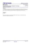
FIT rules define the file structure for all Modules. Having common directory structures and file naming conventions
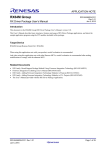
makes it easier for users to quickly find what they need. The required file structure is shown below.
Figure 1 : FIT Module File Structure
Examples of r_<module_name> include:
•
•
•
•
•
•
r_bsp
r_adc_rx
r_sci_async_rx
r_flash_api_rx
r_cgc_rx111
r_vee
(Renesas Board Support Package)
(Analog-to-Digital Converter driver)
(Asynchronous UART driver)
(Flash Rewrite driver)
(Clock Generation Circuit driver)
(Virtual EEPROM Project)
Notice that many of these Module names end with ‘_rx’. This is a postfix that is used to designate which MCUs this
Module can, or will, support. In the case of using ‘_rx’, this signifies that this Module supports all RX devices. Modules
can be more specific as well. For example, the r_cgc_rx111 module only supports the RX111. In the case that a Module
does not have a MCU postfix, such as r_vee, this means that it is not MCU dependent. The r_vee is the Virtual
EEPROM Project and is purely software; therefore it can support any MCU.
Each required folder and file is explained in more detail in the following sections.
3.1
Documentation Folder (‘doc’)
This is folder holds all of the documentation for the Module. At a minimum the Module’s application note will be in
this folder.
3.2
Reference Configuration Folder (‘ref’)
An important feature of FIT is that all of a Module’s compile-time options are contained in one header file. A reference
version of this configuration is stored in the Module’s ‘ref’ (stands for ‘reference’) folder. One required task when
adding a FIT Module to a project is to copy the Module’s reference configuration file, paste it into the r_config folder,
and remove the ‘_reference’ portion of the filename. Users are encouraged to put all of their configuration files in one
folder. By default, the r_config folder name is used. By putting all configuration files in the same folder it makes it easy
for users to find them and requires only one include path to be setup. It also allows for easy back up in a version control
system.
A reference configuration file is supplied so that users always have a known good configuration file in the event that
their custom configuration file is deleted or corrupted.
R01AN1833EU0100 Rev.1.00
Nov 15, 2013
Page 5 of 15
Firmware Integration Technology
3.3
User's Manual
Source Folder (‘src’)
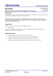
All MCU source code for a FIT Module is stored in the src folder. There can be multiple source folders underneath this
folder if needed. FIT Modules that support multiple MCUs might have a targets folder. Inside of this folder users will
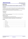
find ports for different MCUs or peripheral versions. Figure 2 shows an example in which a FIT Module has ports for
all RX11x, RX21x, and RX63x MCUs. The ‘x’ character in the name is used as a wildcard. The rx63x folder means that
it will support the RX63N, RX631, RX63T, etc. If users are only using one target folder then they can delete the other
unused folders. For example, if the user is developing using an RX111 then they can delete the rx21x and rx63x folders.
Figure 2 : FIT Module with 'targets' Folder
3.4
Interface Header File (‘r_<module_name>_if.h’)
The interface header file is the one header file that the user will need to #include in their code to use a FIT Module. In
this way the file is an interface to the FIT Module. The interface header file will have all the needed API function
prototypes, data structures, and macros required to use the Module. The naming of the interface file starts with the same
name as the Module with ‘_if.h’ appended.
3.5
readme.txt
The readme.txt file is a simple text file that can be quickly referenced to find important information about a FIT Module.
Information in this file includes:
•
•
•
•
•
•
•
•
•
•
•
•
•
3.6
Module Name
Renesas Document Number
Version
Overview
Features
Supported MCUs
Boards Tested On
Limitations
Peripherals Used Directly
Dependencies (other FIT Modules that are required for this one to work)
How to Add to Your Project
Toolchain(s) Used
File Structure
Other Folders
All of the files and folders in Figure 1 are mandatory except for the utilities folder which has a dotted line. The utilities
folder is an example of extra collateral that can be included with a FIT Module. For example, some modules might
come with code that needs to be run on a PC. This code could be included with the Module in an extra directory.
Another example is a Module that comes in library form. This module could have a folder named lib which would
contain the library.
R01AN1833EU0100 Rev.1.00
Nov 15, 2013
Page 6 of 15
Firmware Integration Technology
User's Manual
4. Using FIT Modules
4.1
Adding FIT Modules to a Project
Since FIT Modules follow a standard file structure, the steps to add most Modules to a project are very similar. The
basic steps that are always required are:
1.
2.
3.
4.
5.
6.
Copy the FIT Module to your project (or wherever you want it to reside).
Add r_<module_name> and r_<module_name>/src to the project’s include path.
Add all source code underneath the r_<module_name> to the project (ensure it is built).
Create a folder named r_config if one does not already exist and add it to the project’s include path.
Copy the reference configuration header file, from r_<module_name>/ref, to the r_config folder.
Remove the ‘_reference.h’ from the configuration file that was just copied to the r_config folder.
Reference the readme.txt or application note for a Module to see the required steps for that specific module.
e2 studio Plug-in
4.2
Renesas provides a plug-in that integrates with e2 studio which automates the process of adding a FIT Module to a
project. The plug-in takes care of all the steps listed in Section 4.1, and it handles additional tasks like automatically
inserting other FIT modules when needed. For information on using the plug-in, please reference the ‘Adding FIT
Modules to Projects’ application note (Renesas Document Number: R01AN1723EU0100).
4.3
Using the Module’s API
After a FIT Module has been added to a project, users need to perform the following steps to use it in their application
code:
1.
2.
Open the Module’s configuration file (in the r_config folder) and review the file for any changes that are
required for the current project. Making changes to a configuration file typically involves changing the value
of #define macros. In some cases commenting out, or uncommenting a #define might be required as well.
Add a #include for platform.h and the Module’s interface header file to any source file that needs to access the
Module.
The header file platform.h comes from the r_bsp and it must be modified by the user to choose which board they are
currently using. Including platform.h is required before including any other FIT Modules. The reason for this is that
platform.h brings in all FIT foundation information that all FIT Modules use.
All users are recommended to review the Module’s application note and interface header file before use so that they are
aware of all available data structures and functions. The application note is located in the Module’s doc folder.
FIT Modules are typically designed to use the Open(), Close(), Read(), Write(), Control() functional paradigm. In this
setup:
•
•
•
•
•
4.4
Open() is used to power on the peripheral and perform initial configuration
Close() is used to disable and power down the peripheral
Read() is used to get data from the Module (e.g. read ADC)
Write() is used to supply data to the Module (e.g. write byte to UART)
Control() takes a command and is used to perform various tasks that expand the functionality of the API
without cluttering the API with many small functions. One of the main benefits of the Control() function is that
the commands can be extended without altering the Module’s API. An example of a Control() function in use
would be to have a command that would abort an on-going transmission with a UART driver.
Interrupt Handling
FIT Modules handle peripheral interrupts internally. Users are alerted of interrupts in one of two ways. One way is
through the use of callback functions. When using this method the user is required to supply a function address to the
FIT Module. When the interrupt occurs the FIT Module will call the function that was provided by the user. When this
method is used users should be very careful of what they put in the callback function. The function will be called from
within an interrupt service routine. If the callback function takes a relatively long period of time to execute, then it can
lengthen the response time of your system.
The other option is to poll for interrupt completion using a Module API function. This method has the benefit of not
being called from within an interrupt service routine, but requires the user to check the Module on a regular basis.
Many FIT Modules will have the option of using callbacks or polling. When polling is desired and the API still requires
a callback function address the user is encouraged to use the FIT_NO_FUNC macro that is defined in the r_bsp. Using
R01AN1833EU0100 Rev.1.00
Nov 15, 2013
Page 7 of 15
Firmware Integration Technology
User's Manual
this macro has the benefit on RX MCUs that it is defined as an address to undefined memory that will cause a bus error
which can be detected and handled by the r_bsp. Users can also use the common NULL macro, but since it is typically
defined to 0, which is a valid RAM address on the RX, it can be harder to detect when used incorrectly.
4.5
Parameter Checking
All FIT Modules contain a macro in their configuration files that pertains to parameter checking. This macro will
always end with ‘CFG_PARAM_CHECKING_ENABLE’ and by default will be set to use the macro
BSP_CFG_PARAM_CHECKING_ENABLE. This macro is defined in the r_bsp and allows the user to globally enable
or disable parameter checking. You can locally override the global setting by setting the macro in the Module.
/**************************************************************************************
Configuration Options
**************************************************************************************/
/* SPECIFY WHETHER TO INCLUDE CODE FOR API PARAMETER CHECKING
Available settings:
BSP_CFG_PARAM_CHECKING_ENABLE:
Utilizes the system default setting
1:
Includes parameter checking
0:
Compiles out parameter checking
*/
#define GPIO_CFG_PARAM_CHECKING_ENABLE
(BSP_CFG_PARAM_CHECKING_ENABLE)
When parameter checking is enabled FIT Modules will check all parameters input by the user to be valid. If a parameter
is found to be invalid then an error code will be returned to the user. This is great for debugging, but it does take extra
memory and execution time. Once development and testing is complete, some users may wish to disable parameter
checking for a module. This reduces code size and execution time; however, if parameter checking is disabled, and an
invalid parameter is input, then improper module operation will likely occur.
R01AN1833EU0100 Rev.1.00
Nov 15, 2013
Page 8 of 15
Firmware Integration Technology
User's Manual
5. Tutorial
This section will lead the user through adding a FIT Module to a project that already has the r_bsp installed. This result
will be a very simple demo, but the point of the exercise is to learn to use FIT Modules. For steps on how to create an
empty project, and add the r_bsp to it, please reference the ‘Project Setup’ section in the Board Support Package FIT
Module application note (R01AN1685EU0230).
The RSKRX111 will be used in this tutorial but the same steps should work for most boards by adjusting which pins are
used.
5.1
Blink a LED
In this section we will add the r_gpio_rx FIT Module. We will use this Module to control GPIO pins on the MCU and
blink an LED. NOTE: This demo is for illustration purposes only; LED definitions do exist in the r_bsp that can access
GPIO pins directly.
1.
With your e2 studio project open, click File >> New >> Renesas FIT Module.
2.
Set the ‘Family’, ‘Series’, ‘Group’, and ‘Target Board’ filters for your board.
3.
Choose r_gpio_rx from the Module list.
4.
Select your project from the ‘Project adding to’ drop-down.
5.
Click ‘Finish’.
6.
The plug-in will pop up a window stating that the r_gpio_rx module has a dependency upon r_bsp v2.30 and
that it appears this Module has already been installed. Click OK.
R01AN1833EU0100 Rev.1.00
Nov 15, 2013
Page 9 of 15
Firmware Integration Technology
7.
User's Manual
The plug-in will pop up another window alerting you that the include and source paths for the project have
been updated. Click OK.
8.
A window will pop up showing you the include directories for your project. Verify that two include paths were
added for the r_gpio_rx Module.
9.
Click Apply and then click OK to close the window.
10. Verify in the Project Explorer pane that r_gpio_rx is now in your project. Underneath the r_gpio_rx folder you
will see the doc folder which holds this Module’s application note. The application note provides the user with
all of the reference information needed for the Module. It also includes sample code that can be cut and pasted
into the user’s application.
11. Verify that the r_gpio_rx configuration file (i.e. r_gpio_rx_config.h) was copied to the r_config directory.
12. Open up the r_gpio_rx_config.h file to see the available compile-time options. In this case the only option is to
enable or disable parameter checking. This is discussed in Section 4.5.
13. We can now use the r_gpio_rx Module in our application code. Open the source file that contains the
application’s main() function.
14. Add a #include for platform.h and the Module’s interface file:
#include "platform.h"
#include "r_gpio_rx_if.h"
R01AN1833EU0100 Rev.1.00
Nov 15, 2013
Page 10 of 15
Firmware Integration Technology
User's Manual
15. Open up the interface file from the r_gpio_rx folder and see the available types and functions. Notice the
comment in the ‘Typedef definitions’ section.
/* The gpio_port_t and gpio_port_pin_t enums are located in the 'targets' folder for
* each MCU. For example, to see these enums for a RX111 look at the following file:
* r_gpio_rx/src/targets/rx111/r_gpio_rx111.h
*/
Typically, all typdefs, enumerators, and structures are contained in the Module’s interface file. For some FIT
Modules that support multiple MCUs, these items will need to change depending on which MCU is chosen. To
offer this capability, some items might be moved to the targets directory as is done here. The r_gpio_rx
module supplies an enumerator for all of the available pins on a MCU. Obviously this enumerator will need to
change depending on what MCU is chosen. This enumerator can even change depending on which pin and
package option for a MCU is chosen.
16. Open up the r_gpio_rx/src/targets/rx111/r_gpio_rx111.h header file and examine the gpio_port_t and
gpio_port_pin_t enumerators.
17. From looking at the interface file, we can get an overview of what functionality is provided by the FIT Module.
If you need extra information remember that an application note is provided for all FIT Modules in the doc
folder. For the r_gpio_rx module we may not need to reference the application note since the Module is fairly
simple. Now that we have an idea of what is offered by the r_gpio_rx module let’s turn an LED on. LED0 on
the RSKRX111 is Port B Pin 7. This can be found from the schematic for the board, or it is commonly defined
in the r_bsp as well. For the RSKRX111, this information could be found by viewing the LED0 macro found
in r_bsp/board/rskrx111/rskrx111.h.
/* LEDs */
#define LED0
PORTB.PODR.BIT.B7
18. To control the port pin we will need to set the pin as an output and then drive it in a certain direction. The
LEDs on the RSKRX111 board have pull-ups on them so to turn on the LED we will need to drive the pin low.
According to the Module’s application note we will need to use the R_GPIO_PinDirectionSet() and
R_GPIO_PinWrite() functions. Both of these functions take a gpio_port_pin_t type for the pin so let’s go
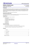
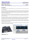
ahead and define a variable for LED0. In your main() function type ‘gpio_’ and then press ‘Control + Space’.
A helper window should pop-up that looks similar to this:
R01AN1833EU0100 Rev.1.00
Nov 15, 2013
Page 11 of 15
Firmware Integration Technology
User's Manual
This is a very helpful feature in e2 studio called autocomplete. The way this works is that e2 studio will scan
your project and give you a list of possible completions to what you have already typed. Since FIT Modules
follow specific naming conventions, it is very easy to find what you need quickly. Press the down key on your
keyboard, or click with your mouse, and select gpio_port_pin_t. Notice that e2 studio proceeds to autocomplete
the variable type. Name the variable led_0_pin and assign it to GPIO_PORT_B_PIN_7.
void main (void)
{
gpio_port_pin_t led_0_pin = GPIO_PORT_B_PIN_7;
}
19. We will now set the pin to be an output using the R_GPIO_PinDirectionSet() function. Type ‘R_GPIO’ in the
editor and then hit ‘Control + Space’ again. Notice that the autocomplete window pops up again and this time
it lists all of the available API functions. Choose the R_GPIO_PinDirectionSet() function from the list. Notice
that once the function name has been filled in, e2 studio also shows the names and types of the variables that
need to be used.
20. For the pin argument type in our variable led_0_pin.
21. For the dir argument type in ‘GPIO_DIR’ and press ‘Control + Space’. Choose GPIO_DIRECTION_OUTPUT
from the autocomplete list. You are probably wondering how we knew to start with ‘GPIO_DIR’. Once again
we are following FIT naming conventions. Enumerator values follow the name of the typedef. In this case the
type is gpio_dir_t so we start typing that name in all caps and use the autocomplete feature to see the available
options.
22. Now that the pin is set as an output, let’s set it low to turn on the LED on. We will use the R_GPIO_PinWrite()
function for this. Go ahead and type ‘R_GPIO’ and then hit Control + Space to autocomplete the function
name.
23. The 1st argument is once again the pin, led_0_pin, and the 2nd argument is the direction which is represented by
the gpio_level_t type. Type ‘GPIO_LEVEL’ and hit Control + Space to see the available options. The options
will be GPIO_LEVEL_HIGH and GPIO_LEVEL_LOW. We want to set the pin low so choose
GPIO_LEVEL_LOW.
24. Add a while(1) infinite loop. Your code should look like the following:
R01AN1833EU0100 Rev.1.00
Nov 15, 2013
Page 12 of 15
Firmware Integration Technology
User's Manual
/* platform.h must be included first. */
#include "platform.h"
#include "r_gpio_rx_if.h"
void main (void)
{
gpio_port_pin_t led_0_pin = GPIO_PORT_B_PIN_7;
R_GPIO_PinDirectionSet(led_0_pin, GPIO_DIRECTION_OUTPUT);
R_GPIO_PinWrite(led_0_pin, GPIO_LEVEL_LOW);
}
while(1)
{
/* Infinite loop. */
}
25. Build the code, and debug it. LED0 should be on.
26. To blink the LED we’ll need to use the R_GPIO_PinRead() function. Use the same methods as before, mainly
the autocomplete feature, to read the pin and set it based on the result.
27. Add a for() loop for delay purposes to make sure we can see the LED blink.
/* platform.h must be included first. */
#include "platform.h"
#include "r_gpio_rx_if.h"
void main (void)
{
uint32_t i;
gpio_port_pin_t led_0_pin = GPIO_PORT_B_PIN_7;
R_GPIO_PinDirectionSet(led_0_pin, GPIO_DIRECTION_OUTPUT);
R_GPIO_PinWrite(led_0_pin, GPIO_LEVEL_LOW);
while (1)
{
for (i = 0; i < 500000; i++)
{
/* Delay so we can see the LED blink. */
}
}
}
if (GPIO_LEVEL_LOW == R_GPIO_PinRead(led_0_pin))
{
R_GPIO_PinWrite(led_0_pin, GPIO_LEVEL_HIGH);
}
else
{
R_GPIO_PinWrite(led_0_pin, GPIO_LEVEL_LOW);
}
28. Build the code and debug it. The LED should be blinking!
R01AN1833EU0100 Rev.1.00
Nov 15, 2013
Page 13 of 15
Firmware Integration Technology
User's Manual
6. Frequently Asked Questions
6.1
What IDEs are supported by FIT?
FIT Modules, and FIT in general, are not tied to any specific IDE. The FIT Plug-in is currently only supported by e2
studio.
6.2
What MCUs are supported by FIT?
The FIT specification can be applied to any MCU. Currently, FIT is only being implemented on RX MCUs.
6.3
What toolchains/compilers are supported?
Which toolchains are supported varies depending on which FIT Module is used. As a baseline requirement, all FIT
Module will support the Renesas supplied toolchain. Other toolchains may be supported based upon requests, and the
amount of work it takes to ‘port’ the code.
6.4
Where can I download FIT Modules?
FIT Modules can be downloaded from the Renesas website alongside other Renesas application notes. To identify a FIT
Module look for the term ‘FIT’ in the name.
6.5
Does FIT provide RTOS support?
Currently FIT Modules are not tied to any RTOS, and do not supply direct RTOS support. However, FIT Modules are
designed such that they do not prevent the user from using an RTOS with the Module.
The r_bsp provides atomic locking mechanisms in the event that the user wants to ensure safe access to shared
resources, but does not want to use an RTOS. These mechanisms should be understood and used with care; when used
improperly, they can cause deadlock in the application code. For more information on this feature, please reference the
‘Board Support Package FIT Module’ application note (R01AN1685EU).
6.6
Can I make my own FIT Module?
Absolutely. Users are encouraged to create their own FIT Modules that can then be used with the FIT Plug-in.
6.7
How do I request a new Module, feature, help, or anything else?
Please contact Renesas using the technical support email:
[email protected]
R01AN1833EU0100 Rev.1.00
Nov 15, 2013
Page 14 of 15
Firmware Integration Technology
User's Manual
Website and Support
Renesas Electronics Website
http://www.renesas.com/
Inquiries
http://www.renesas.com/inquiry
All trademarks and registered trademarks are the property of their respective owners.
R01AN1833EU0100 Rev.1.00
Nov 15, 2013
Page 15 of 15
Revision Record
Rev.
1.00
Date
Nov.15.2013
Description
Page
Summary
—
First edition issued
A-1
General Precautions in the Handling of MPU/MCU Products
The following usage notes are applicable to all MPU/MCU products from Renesas. For detailed usage notes on the
products covered by this document, refer to the relevant sections of the document as well as any technical updates that
have been issued for the products.
1. Handling of Unused Pins
Handle unused pins in accord with the directions given under Handling of Unused Pins in the manual.
⎯ The input pins of CMOS products are generally in the high-impedance state. In operation with an
unused pin in the open-circuit state, extra electromagnetic noise is induced in the vicinity of LSI, an
associated shoot-through current flows internally, and malfunctions occur due to the false
recognition of the pin state as an input signal become possible. Unused pins should be handled as
described under Handling of Unused Pins in the manual.
2. Processing at Power-on
The state of the product is undefined at the moment when power is supplied.
⎯ The states of internal circuits in the LSI are indeterminate and the states of register settings and
pins are undefined at the moment when power is supplied.
In a finished product where the reset signal is applied to the external reset pin, the states of pins
are not guaranteed from the moment when power is supplied until the reset process is completed.
In a similar way, the states of pins in a product that is reset by an on-chip power-on reset function
are not guaranteed from the moment when power is supplied until the power reaches the level at
which resetting has been specified.
3. Prohibition of Access to Reserved Addresses
Access to reserved addresses is prohibited.
⎯ The reserved addresses are provided for the possible future expansion of functions. Do not access
these addresses; the correct operation of LSI is not guaranteed if they are accessed.
4. Clock Signals
After applying a reset, only release the reset line after the operating clock signal has become stable.
When switching the clock signal during program execution, wait until the target clock signal has
stabilized.
⎯ When the clock signal is generated with an external resonator (or from an external oscillator)
during a reset, ensure that the reset line is only released after full stabilization of the clock signal.
Moreover, when switching to a clock signal produced with an external resonator (or by an external
oscillator) while program execution is in progress, wait until the target clock signal is stable.
5. Differences between Products
Before changing from one product to another, i.e. to a product with a different part number, confirm
that the change will not lead to problems.
⎯ The characteristics of an MPU or MCU in the same group but having a different part number may
differ in terms of the internal memory capacity, layout pattern, and other factors, which can affect
the ranges of electrical characteristics, such as characteristic values, operating margins, immunity
to noise, and amount of radiated noise. When changing to a product with a different part number,
implement a system-evaluation test for the given product.
Notice
1.
Descriptions of circuits, software and other related information in this document are provided only to illustrate the operation of semiconductor products and application examples. You are fully responsible for
the incorporation of these circuits, software, and information in the design of your equipment. Renesas Electronics assumes no responsibility for any losses incurred by you or third parties arising from the
use of these circuits, software, or information.
2.
Renesas Electronics has used reasonable care in preparing the information included in this document, but Renesas Electronics does not warrant that such information is error free. Renesas Electronics
3.
Renesas Electronics does not assume any liability for infringement of patents, copyrights, or other intellectual property rights of third parties by or arising from the use of Renesas Electronics products or
assumes no liability whatsoever for any damages incurred by you resulting from errors in or omissions from the information included herein.
technical information described in this document. No license, express, implied or otherwise, is granted hereby under any patents, copyrights or other intellectual property rights of Renesas Electronics or
others.
4.
You should not alter, modify, copy, or otherwise misappropriate any Renesas Electronics product, whether in whole or in part. Renesas Electronics assumes no responsibility for any losses incurred by you or
5.
Renesas Electronics products are classified according to the following two quality grades: "Standard" and "High Quality". The recommended applications for each Renesas Electronics product depends on
third parties arising from such alteration, modification, copy or otherwise misappropriation of Renesas Electronics product.
the product's quality grade, as indicated below.
"Standard": Computers; office equipment; communications equipment; test and measurement equipment; audio and visual equipment; home electronic appliances; machine tools; personal electronic
equipment; and industrial robots etc.
"High Quality": Transportation equipment (automobiles, trains, ships, etc.); traffic control systems; anti-disaster systems; anti-crime systems; and safety equipment etc.
Renesas Electronics products are neither intended nor authorized for use in products or systems that may pose a direct threat to human life or bodily injury (artificial life support devices or systems, surgical
implantations etc.), or may cause serious property damages (nuclear reactor control systems, military equipment etc.). You must check the quality grade of each Renesas Electronics product before using it
in a particular application. You may not use any Renesas Electronics product for any application for which it is not intended. Renesas Electronics shall not be in any way liable for any damages or losses
incurred by you or third parties arising from the use of any Renesas Electronics product for which the product is not intended by Renesas Electronics.
6.
You should use the Renesas Electronics products described in this document within the range specified by Renesas Electronics, especially with respect to the maximum rating, operating supply voltage
range, movement power voltage range, heat radiation characteristics, installation and other product characteristics. Renesas Electronics shall have no liability for malfunctions or damages arising out of the
use of Renesas Electronics products beyond such specified ranges.
7.
Although Renesas Electronics endeavors to improve the quality and reliability of its products, semiconductor products have specific characteristics such as the occurrence of failure at a certain rate and
malfunctions under certain use conditions. Further, Renesas Electronics products are not subject to radiation resistance design. Please be sure to implement safety measures to guard them against the
possibility of physical injury, and injury or damage caused by fire in the event of the failure of a Renesas Electronics product, such as safety design for hardware and software including but not limited to
redundancy, fire control and malfunction prevention, appropriate treatment for aging degradation or any other appropriate measures. Because the evaluation of microcomputer software alone is very difficult,
please evaluate the safety of the final products or systems manufactured by you.
8.
Please contact a Renesas Electronics sales office for details as to environmental matters such as the environmental compatibility of each Renesas Electronics product. Please use Renesas Electronics
products in compliance with all applicable laws and regulations that regulate the inclusion or use of controlled substances, including without limitation, the EU RoHS Directive. Renesas Electronics assumes
no liability for damages or losses occurring as a result of your noncompliance with applicable laws and regulations.
9.
Renesas Electronics products and technology may not be used for or incorporated into any products or systems whose manufacture, use, or sale is prohibited under any applicable domestic or foreign laws or
regulations. You should not use Renesas Electronics products or technology described in this document for any purpose relating to military applications or use by the military, including but not limited to the
development of weapons of mass destruction. When exporting the Renesas Electronics products or technology described in this document, you should comply with the applicable export control laws and
regulations and follow the procedures required by such laws and regulations.
10. It is the responsibility of the buyer or distributor of Renesas Electronics products, who distributes, disposes of, or otherwise places the product with a third party, to notify such third party in advance of the
contents and conditions set forth in this document, Renesas Electronics assumes no responsibility for any losses incurred by you or third parties as a result of unauthorized use of Renesas Electronics
products.
11. This document may not be reproduced or duplicated in any form, in whole or in part, without prior written consent of Renesas Electronics.
12. Please contact a Renesas Electronics sales office if you have any questions regarding the information contained in this document or Renesas Electronics products, or if you have any other inquiries.
(Note 1)
"Renesas Electronics" as used in this document means Renesas Electronics Corporation and also includes its majority-owned subsidiaries.
(Note 2)
"Renesas Electronics product(s)" means any product developed or manufactured by or for Renesas Electronics.
http://www.renesas.com
SALES OFFICES
Refer to "http://www.renesas.com/" for the latest and detailed information.
California Eastern Laboratories, Inc.
4590 Patrick Henry Drive, Santa Clara, California 95054, U.S.A.
Tel: +1-408-919-2500, Fax: +1-408-988-0279
Renesas Electronics Europe Limited
Dukes Meadow, Millboard Road, Bourne End, Buckinghamshire, SL8 5FH, U.K
Tel: +44-1628-651-700, Fax: +44-1628-651-804
Renesas Electronics Europe GmbH
Arcadiastrasse 10, 40472 D üsseldorf, Germany
Tel: +49-211-65030, Fax: +49-211-6503-1327
Renesas Electronics (China) Co., Ltd.
7th Floor, Quantum Plaza, No.27 ZhiChunLu Haidian District, Beijing 100083, P.R.China
Tel: +86-10-8235-1155, Fax: +86-10-8235-7679
Renesas Electronics (Shanghai) Co., Ltd.
Unit 301, Tower A, Central Towers, 555 LanGao Rd., Putuo District, Shanghai, China
Tel: +86-21-2226-0888, Fax: +86-21-2226-0999
Renesas Electronics Hong Kong Limited
Unit 1601-1613, 16/F., Tower 2, Grand Century Place, 193 Prince Edward Road West, Mongkok, Kowloon, Hong Kong
Tel: +852-2886-9318, Fax: +852 2886-9022/9044
Renesas Electronics Taiwan Co., Ltd.
13F, No. 363, Fu Shing North Road, Taipei, Taiwan
Tel: +886-2-8175-9600, Fax: +886 2-8175-9670
Renesas Electronics Singapore Pte. Ltd.
80 Bendemeer Road, Unit #06-02 Hyflux Innovation Centre Singapore 339949
Tel: +65-6213-0200, Fax: +65-6213-0300
Renesas Electronics Malaysia Sdn.Bhd.
Unit 906, Block B, Menara Amcorp, Amcorp Trade Centre, No. 18, Jln Persiaran Barat, 46050 Petaling Jaya, Selangor Darul Ehsan, Malaysia
Tel: +60-3-7955-9390, Fax: +60-3-7955-9510
Renesas Electronics Korea Co., Ltd.
12F., 234 Teheran-ro, Gangnam-Gu, Seoul, 135-080, Korea
Tel: +82-2-558-3737, Fax: +82-2-558-5141
© 2013 Renesas Electronics Corporation. All rights reserved.
Colophon 3.0