1
INSTRUCTION MANUAL
&
FACTORY TEAM
Thank You.
Thank you for selecting the race proven MCD Race Runner. Version 5 is designed to ensure you the
best driving experience in the large scale. Technical superiority, unrivaled endurance, terrific 4WD
handling and strong emotions are the qualities that have always set MCD apart in the world large
scale RC scenario. The same values lie behind the V5, the latest model in the brand, embody the
marriage of design and technology, set in the very DNA of any MCD.
Contents
Introduction
Contents
Warranty and safety precautions
Fuel safety precautions
Make sure your car is properly maintained before you start running!
Operation
Needed equipment
Recommended items(not included)
Mounting the air flow set
Mounting the servo heat plate
Air filter
Mounting the engine
Adjusting the gear ratio
Throttle and brake linkage
Installing the throttle linkage
Installing the brake linkage
Optional rear brake servo installation
Steering servo installation
Steering single-servo installation
Steering double-servo installation
Starting the engine
Preparing the fuel
Shutting the engine off
Carburetor default settings
Starting the engine
Setting the idle-mixture needle L
Setting the mixture-needle H for WOT
Break in procedure
Toe setting
Body cut-out RR5
Cut-out tips RR5
Body cut-out XS-5
Cut-out tips XS-5
Drive-train maintenance
Decal Set RR5
Body Shell Kit - Exploded RR5
Mounting the side body holders RR5
Decal Set XS-5
Body Shell Kit - Exploded XS-5
Mounting the side body holders XS-5
RR5 Decal Set Application
XS-5 Decal Set Application
RR-5 FT Chassis
RR-5 Competition Chassis
XS-5 FT Chassis
XS-5 Competition Chassis
RR5 Competition Default set-up
XS-5 FT & Competition Default set-up
1
1
1
2
2
3
3
3
3
4
4
5
5
5
6
6
7
7
8
8
8
9
9
9
9
9
10
10
10
10
11
11
12
12
12
13
13
13
14
14
14
15
15
16
16
17
17
18
19
Quick Guide MCD Racing Cars
Warranty and safety precautions
With the purchase of this MCD 1:5 car, your car is under two year warranty starting with the date of purchase. This warranty
covers any material or manufacturing faults that might be present at the date of purchase.
This warranty does not cover:
Ordinary wear and tear.
Wearable parts like the clutch or gears.
Damages as a result of misuse by the driver.
Damages from wrong maintenance procedures .
Cosmetic damage.
Please consult your local hobby shop first in case of a warranty claim.
In case you decide to send this product for repair, please attach a proof of purchase. Before you send
your product to your dealer, we recommend you to consult them first (either via telephone or email)
The sender has to pay for shipping costs. Every warranty claim has to be validated by service department
first. Dismissed claims are subject to administrative fees (checking and handling) before we send the items
back. Repairs that are not covered by warranty have to be paid for in advance. MCD Racing cannot be held
responsible for any damages that emerge from or are caused by, directly nor indirect use or misuse of this
product or its accessories.
This product should not be considered as a toy and therefore not suitable for children under the age of 14. The engine
must not be operated interiors.
IMPORTANT:
Advise your local hobby shop before you first start up the engine, especially considering proper operation
and safety precautions. If possible, get a demonstration on how to operate the engine, and make yourself
familiar with it.
Only if and when you fully understand its operation, you should start using the engine. Always be sure to
operate within the safety guidelines indicated below to avoid damages or personal injury. Never try to
modify any part of the engine as this voids the warranty and may lead to damages or personal injury.
Fuel – Safety precautions
Use only minimum 95 Octane gasoline mixed with high quality two-cycle engine oil. Use a 20:1 ratio gasoline to oil.
(e.g. 250ml oil mixed with 5lt Fuel)
Stay away from open fires while fuelling or running the engine. Do not smoke nearby!
Store the fuel in a well ventilated area, away from heat sources, fire or batteries.
Always keep the fuel in a clearly marked container away from the reach of children.
Never handle the engine or the exhaust until they are cooled down. These parts can get up to 170°C when
operating.
In case of eye contact, rinse thoroughly with warm water.
In case of skin contact, rinse thoroughly with warm water and soap. Do not scrub.
Never breathe the exhaust fumes as they are poisonous. Never operate the engine in closed spaces.
If someone is exposed to the exhaust fumes, the person has to be taken out to open air in case of nausea.
Always store your fuel in a sealed container specifically made for gasoline.
2
Make sure your car is properly maintained before you start running!
Check all screws and nuts for a proper and firm seat. Use thread lock, where screws thread into metal.
Never drive without fully charging batteries for the transmitter and receiver against the risk of a runaway.
Always check the brake and throttle linkage before you start the engine.
Be sure the air filter is clean and properly oiled. Never run the engine without an air filter as dust
and debris may enter inside and seriously damage the engine.
Always be sure that there is chain wax inside the CCD Axles.
Always be sure that there is grease inside the cup joint boots.
Always be sure that nobody else uses the same frequency.
Operation
Exhaust fumes are poisonous. Never operate the engine in closed spaces.
Break-in procedure should be payed attention.
Be sure the air filter is clean and well-oiled. Never operate the engine without an air filter attached.
Check the air filter regularly for eventual damages.
Use minimum 95 Octane gasoline mixed with high quality two-cycle engine oil.
Use a 20:1 ratio gasoline to oil. (e.g. 250ml oil mixed with 5lt Fuel)
Use original engine spare parts only.
The Do’s
Switch on the transmitter before starting the
engine.
The Dont’s
Never run with low batteries.
Drive carefully when there are people around.
Never run your car in wet conditions or on tall grass.
Switch engine off first, and then the transmitter.
Never use chemicals for cleaning your car.
Always check the condition of the batteries before
running the engine.
Never run your car without the bodyshell.
Needed Equipment
Li-PO/LiFE Battery
(Max dimensions:
127mm x 57mm x h:39mm)
At least 2 Servos
(Minimum capacity: 25kg for
steering, 15kg for throttle and
brake)*
NiMH Battery
(Max dimensions:
127mm x 57mm x h:39mm)
Receiver*
Transmitter*
Engine*
Or
Battery Charger
Battery extension wire*
Required items if “rolling chassis only” car is purchased.
Air Filter Oil
Thread Lock
Grease
95 or Higher
Octane Gasoline
2 Stroke Oil
(High Quality racing
oil recommended)
Shock Oil
(standart 1000cps)
Tire Glue
Chain Lube
Polycarbonate
Paint
Screwdriver
Needlenose Pliers
PZ 2
PH 1
Wrench
Hex Driver
Sizes: 5.5mm, 7mm, 8mm, 10 mm
3
Sizes: 2mm, 2.5mm, 3mm, 4mm, 5mm
Divider
Cutter
Caliper
Body Reamer
Mounting the Air Flow Set - 7751 (Optional Part)
1. Screw the bottom bracket on the engine (6307 - 4mm allen wrench)
6251
PH1 Self Tap 3x9 mm
6302
Hex Screw M4x12 mm
2. Screw the main insulation plate on the bracket. 3. Screw the main insulation plate directly on the
(6251, 6307)
engine. You don’t need to drill. (6251)
6307
Hex Screw M5x10 mm
4. Screw the spark plug protection on the engine.
(6302)
5. Screw the spark plug protection on the main
insulation plate. (6251)
Mounting the Servo Heat Plate
Screw with 6252
Drill 3mm holes
Optional Barracuda G Performance Exhaust.(7506)
Cut away from the sign if the Air Flow Set(7751)
is mounted.
You can only mount the standart
exhaust shown on the picture.
4
Air Filter
Warning!
Do not use the air filter without oiling.
Dust and particle can damage the engine.
Fixing the air filter:
APPLY FOAM FILTER OIL!
Seal the filter with a plastic safety seal.
Be sure the foams rest properly.
You can drill a 2mm hole to fix the air filter to chassis
with a body pin.
Mounting the Engine
6307
CH Hex Screw M5x10 mm
Fuel return
6307
CH Hex Screw M5x10 mm
6310
Hex Screw M6x20 mm
Fuel intake
6352
CS Hex Screw M5x16 mm
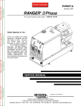
Adjusting the Gear Ratio
When adjusting the gear ratio, depending on the main gear, set the Gear Mesh Selection Plate and the Brake Plate Stiffener
according to figures shown below.
Default Gear set: Main: 64T, Pinion: 21T
(default ratio: 9,14)
Pinion: 18 19 20 21 22 23
Gear Mesh Selection Plate
5
Main Gear: 63T
Brake Plate Stiffener
Pinion: 19 20 21 22 23 24
Main Gear: 62T
Brake Plate Stiffener
Pinion: 20 21 22 23 24 25
Brake Plate Stiffener
Pinion: 23
22
Pinion: 24
23
Pinion: 25
24
21
20
22
21
23
22
19
18
20
19
21
20
Gear Mesh Selection Plate
Gear Mesh Selection Plate
Throttle and brake linkage
The throttle/brake servo controls both linkages and serves two purposes: 1. The throttle linkage controls
the amount of air that goes in to the engine and therefore controls engine rpm. 2. When the throttle linkage
stops at idle, the brake linkage engages.
Installing the throttle linkage
Throttle
1. Turn on your radio first.
2. Check if servos are functioning.
3. Be sure the servo turns on correct direction. (Throttle direction: CCW, Brake direction: CW. As shown
beside. Reverse if direction is not correct!)
4. Install servo horn.
5. Make sure you adjust neutral position as shown in Figure A. If necessary correct the neutral position from
the sub trim menu on your transmitter.
6. Cut the engine cover from the spot indicated in Figure B.
7. After completing the previous steps connect linkage as indicated in Figure A.
8. After adjusting the neutral position install the throttle linkage as indicated in Figure C.
9. Make sure you leave a 0,2mm gap in between the “linkage stopper” and “linkage plastic” as indicated in Figure A.
Cut the supplied silicone
hose to 5mm pieces and
install here.
Brake
Figure A
Leave a 0,2 mm gap(9)
Neutral Position(5)
Figure B
Cut the engine cover from here(6)
Figure C
Screw from here(8)
10. Reduce the throttle end point adjustment(EPA) around %50
from the transmitter.
11. Apply full throttle from the trigger. (Figure D)
Figure D
Rotate the air filter up.
12. Hold full throttle on the transmitter then increase throttle
EPA slowly until there is 0,2mm gap left between the
parts shown in Figure E.
13. After this setting leave the throttle to neutral position.
Figure E
Leave a 0,2 mm gap while on full throttle(12)
14. The throttle linkage is assembled and alignment is done. Check if the linkage is functioning properly.
6
Installing the brake linkage
During operation the brake pads wear over time causing weakening of the brakes. In order to compensate
you should extend the brake linkage by turning it.
1. Make sure you assemble the brake linkages with the dimensions as indicated below.
2. Connect the upper linkage to the front brake and the bottom linkage to the rear brake as indicated in Figure F.
40
2,5
4
Cut one of the supplied springs to 20mm.
15
6
40
10
Cut one of the supplied hoses to 2 pieces of 10mm.
Figure F
Rear brake adjustment collar.
Front brake adjustment collar.
Adjust the brake bias 55% front and 45% rear.
3. After the linkages are installed, switch on your radio and reduce the brake end point from the transmitter
EPA menu to %30.
4. Apply full brake from the trigger and hold.
5. By moving the car back and forth with your hand, start slightly increasing EPA to approx. %50 untill the brakes lock.
6. If it doesn’t lock at %50 turn back to the step 1 and re-adjust.
7. After the brakes are functioning properly adjust the brake bias by using the collars as indicated in Figure F.
8. After the step 7 is complete your brake set-up is finished.
Optional rear brake servo installation
Requires advanced programmable mixing 3 channel radio.
Check your transmitters manual to adjust.
Figure G
7
Install the linkage in this side if double servo is used.
Install the linkage in this side if single servo is used.
Steering servo installation.
You can use single or double steering servos on this car. We recommend using large scale 30x60mm min of 25kg/cm
torque servos.
Steering single-servo installation.
1. Cut the beam with a diagonal pliers as indicated in Figure H.
2. Install servo as shown in Figure I.
3. Insert a 4 mm round pin and lock the Ackerman plate to prevent steering as shown in Figure L. Servo saver will be locked
in the central position.
4. Turn on the radio and install the double horn to neutral position. Perpendicular to servo case.
5. Set steering EPA to approx. %70.
6. Set from the sub trim menu the distances from “the servo horn” to “servo saver” equal at both sides as shown in Figure J.
You can use a divider to measure the distance. (Figure K)
7. Assemble the linkages supplied in the accessory bag and adjust them to same lengths measured in step 6.
8. Install the assembled linkages to the outer holes on the servo saver as indicated in Figure I and Figure J.
9. Remove the round pin inserted in step 3.
10. Adjust steering EPA to max. possible left then max. possible right from the transmitter. The servo should stop turning
when the steering reaches its maximum travel.
11. After step 10 is completed your steering single servo installation and set-up is finished.
Figure I
Figure H
Figure J
x
x
Cut the beam with diagonal pliers(1).
Single servo hole
Twin servo holes
Steering double-servo installation.
Caution!
Figure K
Double-servo installation is critical and should be handled carefully. If not installed
properly the servos will work against each other and damage themselves.
1. Install servos as shown in Figure L.
2. Insert a 4 mm round pin and lock the Ackerman plate to prevent steering as shown in Figure L.
Servo saver will be locked in the central position.
3. Turn on the radio and install the single horns to neutral position as shown in Figure L.
4. Set steering EPA to approx. %70.
5. Measure the distance A shown in Figure L with a divider.
6. Set from the sub trim menu, the servo 1 horn distance to servo saver
Figure L
inner hole(distance B) is equal to distance A.
7. Repeat step 6 for servo 2 distance C and check if the distance B has
remained same.
Distances may change during sub trim. Remove the horns of servo 1
and servo 2 and swap them then repeat step 5,6 and 7.
Make sure the distances A, B and C are equal!
8. Assemble the linkages supplied in the accessory bag with the same
length with distance A.
9. Install the assembled linkages to the inner hole on the servo saver for
faster response (make sure the distance D is equal to the servo horn
distance E as shown in Figure L).
10. Remove the round pin inserted in step 2.
11. Adjust steering EPA to max. possible left then max. possible right from
the transmitter. Be sure the servo stops turning before the steering
reaches its maximum travel.
12. After step 11 is completed your steering single servo installation
and set-up is finished.
Insert a 4 mm round pin and lock the
ackerman plate to prevent steering(3,2).
D
D
B
C
A
A
E
E
Servo 2
Servo 1
8
Starting the Engine
Preparing fuel
Fill the fuel tank. Use only minimum 95 Octane gasoline mixed with high quality two-cycle engine oil.
Use a 20:1 ratio gasoline to oil. (e.g. 250ml oil mixed with 5lt Fuel)
Shutting the engine off
Push engine stop switch E shown in Figure M. ( For RR5 cut the body from the indicated
area in order to access the engine switch when the body is mounted.)
Caution!
Be sure you understand all engine instructions before attempting to start the engine. Turn on the transmitter
first, then the receiver before starting the engine.
Carburetor default settings
Slight adjustments of the carburetor might be needed depending on the external factors such as mixture,
spark plug, muffler and environmental factors(air pressure, humidity and temperature).
Fine-tuning idle and full throttle settings will only work after the engine is fully broken in. The factory settings
provide a rich mixture that results in a significant blue smoke from the exhaust.
In case the idle-mixture needle L or the main needle H were accidentally altered, turn the setting screws H
and L clockwise as far as they will go. Afterwards, turn the H screw 1hour 30mins +- 5mins turns counter-clockwise
and the L-screw 1 hour 10mins +- 5mins counter-clockwise. (As explained in Figure O below)
Figure O
Figure N
H Needle:
+
+1Hour 30mins
H needle
L needle
+- 5mins
1 hour(60mins)
Idle Screw
L Needle:
1Hour 10mins
+- 5mins
30mins
+
1 hour(60mins)
+10mins
Figure M
Starting the engine
The engine is provided with an integrated fuel pump to get fuel to the
carburetor. The carburetor features a manual pump (B) with a transparent
cover to see the fuel flow. Follow the steps below to start the engine.
1. Pump the primer bulb on the carburetor(B in
Figure M) until it is filled.
2. Set the choke lever(A in Figure M) as shown.
3. Pull the starter cord 3 times slowly for the fuel
to get in the cylinder.(Do not pull the cord fast
and more than 50-60cm)
4. Set the choke lever as shown.
5. Pull the starter cord rapidly 5-6 times until the
engine starts.(Do not pull the cord more than 50-60cm)
6. When the engine starts, set the idle if its too high
(vehicle moves at idle) or too low(engine stops running
from the idle screw shown in Figure N.
7. If the engine does not start set the carburetor to
default settings as indicated above.
9
5mins
5mins
Caution!
- Pulling the pull-start cord to its full length can damage the pull starter.
- Pull about 50-60cm of the cord. (first try slowly with the ignition disengaged)
- Never apply too much force to the pull-start mechanism.
Caution!
The mixture gets too rich if too much fuel enters the crankcase or the choke stays closed for too long. This
causes the engine to stall. In this condition, the pull-start can only be operated with considerable force. Do not
try to start the engine, but rather drain the excess fuel to prevent damage on the engine or the pullstart
mechanism. Proceed as outlined below:
- Take out the spark plug and let the electrode dry
- Fully open the choke
- Pull the starter cord several times. CAUTION: fuel may spatter from the combustion chamber and catch fire,
and if contacted irritate your eyes and skin.
- Reassemble the spark plug.
- Start the engine again.
Setting the idle-mixture needle L
- Let the engine warm up.
- If the engine responds weak when throttle is pulled , the idle-mixture is too lean.
- Richen the mixture as you slowly turn the idle-mixture needle counter-clockwise by 5 min increments.
(As indicated in Figure O on the previous page)
- If the engine responds to throttle input with stuttering and smoke plumes from the exhaust, the
idle-mixture is too rich.
- Lean the mixture as you slowly turn the idle-mixture needle clockwise by 5 min increments.
Setting the mixture-needle H for WOT
- Prop the car and let the warmed up engine run at full throttle for a short duration.
- Lean the mixture as you slowly turn the mixture needle H clockwise by 5 min increments.
- Richen the mixture as you slowly turn the mixture needle H counter-clockwise by 5 min increments.
- We recommend a setting slightly on the rich side to prolong the engine life.
Caution!
The mixture must not be set too lean under any circumstances! Engine lubrication solely depends on the oil contained in
the fuel. Too little fuel in the mixture leads to overheating and piston squeezing due to lack of lubrication. During operation, a lightly blue smoke trail should be visible. Otherwise, immediately stop the engine and richen the mixture accordingly.
Also make sure that the cylinder is cooled enough with fresh air to avoid overheating. Spark plugs are subject to wear,
especially during break in. Always keep spare plugs of the CMR 7H class at hand. An unsuitable spark plug will make the
engine run rough and hamper carburetor settings. Check spark plugs for visual defects and proper electrode clearance.
Break-in procedure
The engine performs best after a short break-in period due to the engines internal parts manufacturing methods. During
thisbreak-in, the piston’s and liner’s surfaces mate each other for best performance and best break-in possible. Break in
the engine by driving for around 1tank of fuel before full throttle may be applied.
Toe Setting
Toe-in:
Mount the toe inserts pointing the direction that the hubs will be installed
(L or R) as shown beside.
e.g. If the hub will be installed on the left side, the inserts should be pointing L
for toe-in.
Toe-out:
Though not used frequently if toe-out desired in the rear, simply swap left and
right hubs. You will obtain same amount of toe-out.
Hub
The toe angle can be changed by replacing the inserts with the desired angle.
The degree which defines the toe-angle can be noticed by the sign on the
inserts as indicated in the figure below.
Toe inserts angle
0°
1°
2°
3°
Toe inserts pointing left
10
Body cut-out
Exhaust
Power switch access
Figure P
Important!
We recommend to ream out more
holes for cooling if the weather
temprature gets too high.
Fuel tank access
Air intake
Pull start access
Cut-out tips
Engine-off access
1. Drill holes on the corners and center before cutting out.
2. Cut the specified lines with PC scissors.
3. Scratch the edges with the cutter tool shown in Figure P.
4. Bend and brake the pieces towards inside of the body.
(We recommend to use mechanic gloves during these steps)
11
Body cut-out
Important!
Power switch access & Air intake
Figure P
Cut-out tips
We recommend to ream out more
holes for cooling if the weather
temprature gets too high.
Pull start & Engine-off access
Carburator access & Air intake
1. Drill holes on the corners and center before cutting out.
2. Cut the specified lines with PC scissors.
3. Scratch the edges with the cutter tool shown in Figure P.
4. Bend and brake the pieces towards inside of the body.
(We recommend to use mechanic gloves during these steps)
Drive-train maintenance
Important!
Apply chain lube inside the CCD Axles
after every 3-4 tanks.
Important!
Apply grease inside the boots and check frequently.
Replace them if they are ripped.
12
13
6251
6251
5002
- Drill a hole on the body shell for side body mounts as shown
5002 RR5 Body Shell Composite Accessories
Mounting the side body holders.
5002
5008
5007
5001 Body Shell Kit Complete
5002
5007
5008
Screw the body holders onto each side guard.
(6252 BH PH1 Self Tap 3x13 mm)
6251
5002
6251
5007
5008
5002
5002 - Decal Set
14
5008
5012 XS-5 Front/Side Small Body Holders
Front Body Holder - Side Body Holders
Mounting the side body holders.
5007
5007
5008
5011
5009 Body Shell Kit Complete
5009
5007
6251
Screw the body holders onto front bumper.
(6252 BH PH1 Self Tap 3x13 mm)
5007
5010
5007
6251
5011
5008
5013 - Decal Set
Screw the side body holders onto each side guard.
(6252 BH PH1 Self Tap 3x13 mm)
5011
6201
RR5 Decal Set Application
XS-5 Decal Set Application
15
RR5 FT Chassis
RR5 Competition Chassis
16
XS-5 FT Chassis
XS-5 Competition Chassis
17
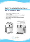
Factory Default Set-up
TOTAL
CASTER
LSD
OPEN
LSD Ramp
60°
90° 120°
LSD
SOLID
LSD Ramp
60°
90° 120°
LSD
OPEN
18°
FT & Competition
CASTER BLOCK
6°
1°
10°
39-40
mm
LSD Ramp
60°
90° 120°
KICK-UP
KICK-UP
LSD
OPEN
LSD
SOLID
LSD
8°
ACKERMAN
8°
OPEN
TOE
COG
1000
1000
4646,5
mm
25
mm
OUT BOARD TOE IN
2x2mm
0°
2x2mm
1°
2°
3°
50-51
mm
ANTI-SQUAT
3°
short
ANTI-SQUAT
3°
3,5mm
1
2
3
4
5
6
7
8
9
10
11
12
13
14
15
16
17
18
3,5mm
Final Ratio Engine Center Diff
62
7.44
25
24
62
7.75
63
7.88
24
23
62
8.09
63
8.22
23
23
64
8.35
62
8.45
22
63
22
8.59
22
64
8.73
62
8.86
21
63
21
9.00
21
64
9.14
9.30
20
62
20
63
9.45
64
9.60
20
9.95
19
63
64
10.11
19
64
10.67
18
IN BOARD
TOE-IN
1°
COG
IN BOARD
TOE-IN
1°
25
mm
You can download the set-up sheet from: www.mcdracing.com/support
Factory Default Set-up
LSD
OPEN
LSD
LSD Ramp
LSD Ramp
60°
OPEN
90° 120°
60°
90° 120°
LSD
TOTAL
CASTER
OPEN
18°
CASTER BLOCK
6°
1°
10°
43-44
mm
LSD Ramp
60°
90° 120°
KICK-UP
KICK-UP
8°
ACKERMAN
8°
Astro Grip
1000
W
COG
TOE
W
1000
3x3mm
4646,5
mm
40-45
mm
OUT BOARD TOE IN
3x3mm
0°
1°
2°
3°
48-49
mm
short
ANTI-SQUAT
ANTI-SQUAT
1
2
3
4
5
6
7
8
9
10
11
12
13
14
15
16
17
18
Final Ratio Engine Center Diff
62
7.44
25
24
62
7.75
63
7.88
24
23
62
8.09
63
8.22
23
23
64
8.35
62
8.45
22
22
63
8.59
64
8.73
22
62
8.86
21
21
63
9.00
9.14
21
64
20
62
9.30
9.45
20
63
9.60
20
64
19
63
9.95
19
64
10.11
10.67
18
64
3°
COG
3°
IN BOARD
TOE-IN
3°
IN BOARD
TOE-IN
3°
40-45
mm
You can download the set-up sheet from: www.mcdracing.com/support
1
2
MCD XS5 Factory Team
A
4
3
2612
8254
(not inc.) 3401
6501
6452
2614
2609
2611
3401
6751
2613
2608
6201
6303
3406
8251
(not inc.)
6309
6051
3407
6203
e
t-R
n
Fro
&
ar
al
ti
ren
iffe
D
ter
n
Ce
6051
6701
6151
1
6452
3409
6201
3009
6102
6202
6503
6007
6004
2018
2015
6051
6201
3010
2312
3401
6351
3401
2309
3405
3008
2306
2308
6455
6006
3006
3008
7001
6051
4
2309
3013
2310
6004
6053
1003
6201
1001
1004
7501
(not inc.)
6304
t&
n
Fro
4001
4004
6552
6053
3223
3402
6
7
3206
E
3402
6351
5
D
6306
6502
6351
2310
3404
6502
3006
1002
3205
3
2308
6455
6006
4004
6454
6004
7003
3401
3012
6201
2306
6502
6351
3401
3405
6502
6702
C
6102
4452
7252
3012
3401
6752
7002
3001
6203
6201
6251
6101
7002
7004
6306
6201
7752
6252
5012
6305
3401
6456
3011
7002
3603
3407
3408
3003
3005
6203
7005
4151
6002
3602
4006
6201
6502
6051
2013
3220
6203
6402
6402
6301
2003
900101X
Electric Motor Conversion Kit
(not included)
4151
2011
3809
4451
6502
3007
6052
2
6551
6201
3404
6201
7501
(not inc.)
6302
4601
3005
3003
6051 6201
2017
2018
6003
6309
2313
2305
6203
6252
5012
4005
6306
2312
3011
3001
2304
2313
2018
3002
6102
3004
3401
3012
6456
2008
6054
2007
2012
2006
2005
F/R Differential Ass'y
= 2001
2004
Center Differential Ass'y = 2002
6201
2001
4151
6051
2309
6203
6051
2309
6201
2015
3010
6202
4151
2307
6102
4154
6201
4152
6051
2017
6003
4151
6007
2011
6004
2018
3002
3602
6004
2002 6051
2018
6502
3801
6351
6203
3004
3603
6651
2601
6201
3220
6452
3408
4152
2016
3403
4151
3401
3403
6503
2314
4154
2605
2016
6004
6503
4007
6201
6503
6502
2605
3401
2001
6309
6201
6201
2602
2602
6201 4251
6309
6203
7753
4153
2607
6453
2603
2604
6311
3401
3218
6503
4304
3803
6201
3409
B
6311
3808
6001
4303
4251
3807
3805
3218
F
6201
6202
7506 Tune Pipe Set
(not included)
6203
6352
6001
3806
D
6252
4602
(not inc.)
6352
7253
7256
6201
3801
6201
6002
6452
6201
7255
6252
8502
(not inc.)
5008
7253
7251
6553
3405
6252
4751
E
6152
4752
8501
(not inc.)
8251
(not inc.)
2014
7502
(not inc.)
6301
4605
4601
7254
6005
3801
4753
8254
(not inc.)
6251
A
(not inc.)
6308
7751
4604
4603
7504
7505
6251
6307
6005
7251
3804
6305
4752
C
6456
6504
6001
6452
6307
2311
6310
3401
2613
7751
4155
3810
6313
2612
3401
2611
2613 6452
6501
6302
6307
7751
8001
(not inc.)
3406
2613
6452
8
(not inc.)
6303
6551
4158
B
7
EXPLODED VIEW
Please check www.mcdracing.com/parts for up-to-date parts list.
6314
6
5
Re
ck
ho
S
ar
3215
3216
3207
A
6312
r
rbe
o
bs
6502
6551
3222
3205
3213
3214
6703
3216
6704
3208
3221
F
Revision
24.09.2013
Scale
1:6
Sheet
8
A3
1
2
4
3
6
5
7
EXPLODED VIEW
A
(not inc.)
8001
(not inc.)
Please check www.mcdracing.com/parts for up-to-date parts list.
6303
6313
2612
3401
2611
2613
2613
6452
6314
6501
2612
B
8254
(not inc.)
3810
6452
2613
2608
2614
2609
2611
6452
3401
6751
2613
3401
6501
6201
6452
2014
C
8251
(not inc.)
8502
(not inc.)
3805
3803
2016
3218
6503
6201
6309
3801
3403
3401
6351
6051
2017
6003
3220
4151
2001
4151
6007
2011
6203
6202
4151
6201
2015
6004
2018
6051
t&
n
Fro
R
t
ne
Pla
6203
6201
6051
2309
2313
2304
6252
3001
6315
3401
6402
3
6502
D
3006
6006
3013
6306
3006
6004
2310
1003
6053
6502
6351
1001
1004
4001
3401
3405
6006
4
6454
6004
2310
t&
n
Fro
4004
Re
3205
6502
3206
6551
3216
3219
3222
3221
3208
3215
F
3223
3402
3205
6
r
rbe
o
s
Ab
3216
3207
6552
6053
ck
ho
S
ar
6502
5
E
3402
6502
6351
6304
3008
2
3404
1002
6351
2308
3006
2021
6051
7001
3401
2308
2309
3012
3405
6051
3012
4004
2309
2003
7003
6201
2306
4452
6502
7252
6305
2306
6702
6102
2312
6203
6252
5012
6502
3009
3401
C
7002
6201
6201
7002
3401
3001
6203
3012
6201
7004
4006
3809
4451
3404
6402
2021
6503
6551
4601
3011
6752
6101
3010
6203
6302
4005
3007
t
ren
fe
Dif
2309
6051
6102
6203
2018
6003
2018
6309
2305
6456
7002
6251
6351
2313
6102
6004
6007
2018
2015
6201
6051
3005
3003
6201
6051
3401
2019
1
6201
6502
6202
3003
3005
6203
2011
4151
4154
2017
6306
ial
2020
F
2018
6456
2312
3011
3010
r
ea
6004
2025
3002
3004
6203
3004
3002
E
6051
2026
4151
2001
6102
5012
6309
6203
6201
2307
7005
6201
4151
2314
6651
2016
6051
6502
6311
6309
4154
4152
6201
3403
6503
6201
4152
6502
6302
2601
2018
6001
4251
4153
2602
2605
3801
5008
6311
2603
2604
3808
3220
6201
2607
3802
3405
900101X
Electric Motor Conversion Kit
(not included)
6201
6201
3401
4153
B
6309
6503
6202
6001
4007
3218
7753
6201
6305
4251
6203
6352
7256
6252
6201
6252
3806
D
7255
3807
8501
(not inc.)
6352
4601
7251
3801
6252
4605
7254
7253
7251
3804
(not inc.)
7506 Tune Pipe Set (opt.)
(not included)
6301
4155
6504
6001
4752
4753
8254
(not inc.)
6005
6553
3406
4602
4603
6310
6456
4752
8251
(not inc.)
4604
6152
3401
6303
6307
4158
6005
A
(not inc.)
2311
6551
3406
8
7
Revision
24.09.2014
Scale
1:6
Sheet
8
A3
0&'55&RPSHWLWLRQ
$
QRWLQF
%
QRWLQF
QRWLQF
QRWLQF
'
(
O
)
W
HQ
IHU
3
WHU
Q
QW
)UR
(
HU
RUE
V
$E
N
RF
6K
U
HD
5
'
)5'LIIHUHQWLDO$VV
\ &HQWHU'LIIHUHQWLDO$VV
\ LI
W'
H
ODQ
&H
LDO
&
WLD
UHQ
IIH
'L
W
QH
3OD
DU
H
5
W
Q
)UR
QRWLQF
%
QRWLQF
&
$
QRWLQF
7XQH3LSH6HWRSW
QRWLQFOXGHG
(;3/2'('9,(:
3OHDVHFKHFNZZZPFGUDFLQJFRPSDUWVIRUXSWRGDWHSDUWOLVW
)
5HYLVLRQ
6FDOH
6KHHW
$
The Winning Experience
We observe the racers and gather information from the tracks, with these information we rapidly develop new
race oriented ideas and re-implement them into our race machines. This is the experience behind this cycle
that leads us at the championships.