1
ECE391: Computer Systems Engineering
Machine Problem 2
Spring 2015
Checkpoint 1: Monday, March 2, 7pm
Checkpoint 2: Monday, March 9, 7pm
Device, Data, and Timing Abstractions
Read the whole document before you begin, or you may miss points on some requirements.
In this machine problem, you will extend a video game consisting of about 4,000 lines of code with additional graphical
features and a serial port device. The code for the game is reasonably well-documented, and you will need to read
and understand the code in order to succeed, thus building your ability to explore and comprehend existing software
systems. Most code that you will encounter is neither as small nor as well documented—take a look at some of the
Linux sources for comparison—but this assignment should help you start to build the skills necessary to extend more
realistic systems. As your effort must span the kernel/user boundary, this assignment will also expose you to some of
the mechanisms used to manage these interactions, many of which we will study in more detail later in the course.
Before discussing the tasks for the assignment, let’s discuss the skills and knowledge that we want you to gain:
• Learn to write code that interacts directly with devices.
• Learn to abstract devices with system software.
• Learn to manipulate bits and to transform data from one format into another.
• Learn the basic structure of an event loop.
• Learn how to use the pthread API.
Device Protocols:
We want you to have some experience writing software that interacts directly with devices and must adhere to the
protocols specified by those devices. Similar problems arise when one must meet software interface specifications,
but you need experience with both in order to recognize the similarities and differences. Unfortunately, most of the
devices accessible from within QEMU have fully developed drivers within Linux. The video card, however, is usually
managed directly from user-level so as to improve performance, thus most of the code is in other software packages
(e.g., XFree86).
We were fortunate to have a second device designed by Kevin Bassett and Mark Murphy, two previous staff members.
The Tux Controller is that funny little game controller attached to each of the machines in the lab.
The Tux Controller connects to the USB port of the lab machine. An FTDI “Virtual Com Port” (VCP) driver makes the
USB port appear to software as a standard (old fashioned) RS232 serial port. We can then set up QEMU so that one of
the emulated serial ports on the virtual machine maps to the emulated serial port connected to the Tux Controller. In
this assignment, you will write code that interacts directly with both the (emulated) video card and the game controller
board.
Device Abstraction:
Most devices implement only part of the functionality that a typical user might associate with them. For example, disk
drives provide only a simple interface through which bits can be stored and retrieved in fixed-size blocks of several
kB. All other functionality, including everything from logical partitions and directories to variable-length files and filesharing semantics, is supported by software, most of which resides in the operating system. In this machine problem,
you will abstract some of the functionality provided by the Tux controller board.
Format Interchange:
This machine problem gives you several opportunities for working with data layout in memory and for transforming
data from one form to another. Most of these tasks relate to graphics, and involve taking bit vectors or pixel data laid out
in a form convenient to C programmers and changing it into a form easily used by the Video Graphics Array (VGA)
operating in mode X. Although the details of the VGA mode X layout are not particularly relevant today, they do
represent the end product of good engineers working to push the limits on video technology. If you work with cuttingedge systems, you are likely to encounter situations in which data formats have been contorted for performance or to
meet standards, and you are likely to have to develop systems to transform from one format to another.
Event Loops:
The idea of an event loop is central to a wide range of software systems, ranging from video games and discrete event
simulators to graphical user interfaces and web servers. An event loop is not much different than a state machine
implemented in software, and structuring a software system around an event loop can help you to structure your
thoughts and the design of the system.
Threading:
Since the advent of faster processors, it became possible to exploit code parallelism by creating multiple threads.
Multiple threads of execution also allow logical separate tasks to be executed using synchronous operations. If one
thread blocks waiting for an operation to complete, other threads are still free to work. Note that threads are different
from processes. A thread is the smallest unit of processing that can be scheduled by an operating system. Multiple
threads can exist within the same process and share resources such as memory. Different processes cannot share these
resources. On a single processor, multithreading generally occurs by having the processor switch between different
threads, which is known as context switching. Since context switching happens frequently, the user perceives the
threads as running concurrently.
In this machine problem, we illustrate the basic concepts by using a separate thread to get updates from the keyboard.
You will need to synchronize your code in the main thread with this helper thread using a Posix mutex. You will also
need to add a new thread to take input from the tux controller. This thread may also need synchronization to guarantee
correctness.
You may want to read the class notes on Posix threads to help you understand these interactions. Later classes will
assume knowledge of this material.
Software examples and test strategies:
In addition to these five learning objectives for the assignment, this machine problem provides you with examples of
software structure as well as testing strategies for software components.
Two of the files include main functions that are only included when a defined value is changed at the top of the file. By
setting this value to one and compiling the file by itself, you create an executable that tests the functionality provided
by the file in the absence of other code. When you design software interfaces, you should do so in a way that allows
you to test components separately in this manner and thus to deal with bugs as soon as possible and in as small a body
of code as possible. Individual function tests and walking through each function in a debugger are also worthwhile,
but hard to justify in an academic setting. The input control file allows you to develop and test your Tux controller
code without using the game interface. Since the game changes the display to mode X, testing without the hassle of
changing back to text mode can be quite helpful.
The modex.c file is compiled by the Makefile to create a separate executable that returns your system to text mode.
We also made use of a technique known as a memory fence to check some of the more error-prone activities in the
file; read the code to understand what a memory fence is and what it does for you.
The Pieces Provided
You are given a working but not fully-functional copy of the source tree for a maze game along with a skeletal kernel
module for the Tux controller. The Tux controller boards are attached to each machine in the lab.
The table below explains the contents of the source files.
assert.c
blocks.s
input.c
maze.c
mazegame.c
modex.c
text.c
Support for assertions and cleanups as design and debugging aids.
Graphic block images of the maze, the player, fruits, etc.
Input control. Provides for initialization and shutdown of the input controller. The version provided
to you supports keyboard control. You must write the support for the Tux controller. This file is not
compiled with the rest of the game and should be used only to test your inputs separately from the
game. Can be compiled stand-alone to test the input device.
Maze generation and logic. Creates the maze; creates, checks for, and consumes fruit; checks for
win conditions. Transforms the block image data in blocks.s into pixelized graphic images of
maze lines and columns for use by modex.c in drawing parts of the logical view. Can be compiled
stand-alone to test maze generation.
Multithreaded main process of the mazegame. There is a thread that controls the game logic, including the main event loop, level set up, all timing logic, display control logic (motion and scrolling).
Includes a computer-controlled player as well as one using the regular input control. Another thread
is created to handle keyboard control. You will eventually need to add another thread for the Tux
Controller control.
Functions to support use of VGA mode X. Includes things like switching from text mode to mode
X and back, and clearing the screens. Provides a logical view window abstraction that is drawn in
normal memory and copied into video memory using a double-buffering strategy. When the logical
view is shifted, data still on the screen are retained, thus only those portions of the logical view that
were not previously visible must be drawn. Finally, supports mapping from pixelized graphics in
formats convenient to C into drawing a screen at a certain logical position. Relies on maze.c to
provide vertical and horizontal lines from the maze. Is also compiled stand-alone to create the tr
text mode restoration program.
Text font data and conversion from ASCII strings to pixelized graphic images of text (you must write
the latter).
We have also included two stripped binaries to illustrate your end goal. The mazegame-demo program is a fully
working version of the game that allows both keyboard and Tux controller input. The input-demo program is a
stand-alone compilation of input.c, again allowing both forms of input.
The tr Program
The make file provided to you builds both the game and a text-mode-restoration program called tr. The latter program
is provided to help you with debugging. One difficulty involved with debugging code that makes use of the video
hardware is that the display may be left in an unusable (i.e., non-text-mode) state when the program crashes, hangs, or
hits a breakpoint. In order to force the display back into text mode for debugging purposes (or, if you are not running
the program in a debugger, to regain control of your shell), you can run the tr program. Unless you are fairly confident
in your ability to type without visual feedback, we recommend that you keep a second virtual console (CTRL-ALT-F1
through F6) logged in with the command to execute the text restoration program pre-typed, allowing you to simply
switch into that console and press Enter. Using this program is substantially easier than rebooting your machine to put
it back into text mode.
You should also look at the cleanup handlers provided by the assert module (assert.h and assert.c). These
cleanup handlers provide support for fatal exceptions, putting the machine back into a usable state when your program
crashes. However, there may be instances and problems not covered by the handlers, and GDB can stop the program
before the handlers are invoked, leaving the machine in an unusable state until you restore text mode with tr.
Mode X and Graphic Images
Mode X is a 256-color graphics mode with 320x200 resolution. It was not supported by the standard graphics routines
that came with the original VGAs, but was supported by the VGA hardware itself, and was quickly adopted as the standard for video games at the time because of certain technical advantages over the documented 256-color mode (mode
13h, where the ‘h’ stands for hexadecimal). In particular, mode X supports multiple video pages, allowing a program
to switch the display between two screens, drawing only to the screen not currently displayed, and thereby avoiding the
annoying flicker effects associated with showing a partially-drawn image. This technique is called double-buffering.
Each pixel in mode X is represented by a one-byte color value. Although only 256 colors are available in mode X, the
actual color space is 18-bit, with 6-bit depth for red, green, and blue saturation. A level of indirection is used to map
one-byte pixel color values into this space. The table used in this mapping is called a palette, as it is analogous to a
painter’s palette, which in theory holds an infinite range of colors, but can only hold a few at any one time. Palettes
are often used to reduce the amount of memory necessary to describe an image, and are thus useful on embedded
devices even today. For your final projects, some of you may want to play with graphic techniques such as palette
color selection to best represent a more detailed image and dithering to map a more detailed image into a given palette.
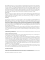
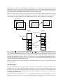
The mapping between screen pixels and video memory in mode X is a little contorted, but is not as bad as some of the
older modes. The screen is first separated into blocks four pixels wide and one pixel high. Each block corresponds to
a single memory address from the processor’s point of view. You may at this point wonder how four bytes of data get
crammed into a single memory address (one byte in a byte-addressable memory). The answer, of course, is that they
don’t. For performance reasons, the VGA memory was 32-bit, and the interface between the processor and the VGA
is used to determine how the processor’s 8-bit reads and writes are mapped into the VGA’s 32-bit words. For example,
when the processor writes to a memory address, four bits of a specific VGA register are used to enable (1 bits) or
disable (0 bits) writes to 8-bit groups of the corresponding word in VGA memory. When drawing rectangles of one
color, this mask reduces the work for the processor by a factor of four. When drawing images, however, it poses a
problem in that adjacent pixels must be written using different mask register settings. As changing a VGA register
value is relatively slow, the right way to use mode X is to split the image data into four groups of interleaved pixels, set
the mask for each group, and write each group as a whole using the x86 string instructions (you won’t need to write
any of these, although you may want to look at how it is done in the existing code or in the x86 manual).
address
0xA1284
(0xA1234 + 80)
address
0xA1234
address
0xA1236
address
0xA1237
0 1 2 3 0 1 2 3 0 1 2 3 0 1 2 3
0 1 2 3
address
0xA12D4
(0xA1234 + 160)
address
0xA1235
0 1 2 3
...
...
...
(all at 0xA1236)
plane 3
plane 2
plane 1
plane 0
Mode X video memory is memory-mapped and runs from (physical) memory address 0xA0000 to 0xAFFFF, for a
total of 216 addresses and 256 kB of addressable memory (counting all four planes). The addresses used in your
program are virtual rather than physical addresses, a concept to be discussed later in the course; don’t be surprised if
they are not the same as the physical addresses, though. A full screen occupies 320 × 200/4 = 16, 000 addresses, so
four fit into the full memory, with a little extra room. The VGA can be directed to start the display from any address in
its memory; addresses wrap around if necessary. In the figure shown above, for example, the screen starts at address
0xA1234.
Due to the timing behavior of emulated interactions with video memory, the code provided to you does not use a
traditional double-buffering model in which the off-screen image is drawn directly within video memory. As with
double-buffering, we do maintain two regions within the video memory for screen images. However, we use regular
memory to maintain an image of the screen and to update that image in place. When a new image is ready for display,
we copy it into one of two regions of the video memory (the one not being displayed) and then change the VGA
registers to display the new image. Copying an entire screen into video memory using one x86 string instruction
seems to take about as long as writing a small number of bytes to video memory under QEMU, thus our image display
is actually faster than trying to draw a vertical line in video memory, which requires one MOV instruction per vertical
pixel.
Only the modex.c file relies on mode X. The rest of the code should use a graphics format more convenient to C. In
particular, an image that is X pixels wide and Y pixels high should be placed in an array of dimensions [Y ][X]. The
type of the array depends on the color depth of the image, and in our case is an unsigned char to store the 8-bit
color index for a pixel. The block images in blocks.s already use this format, as do the line generation routines in
maze.c. When you write code to generate graphic images from text, as described in a later section, you should use
the same format.
Graphical Mapping in the Game
The game defines a two-dimensional world of pixels, and the screen at any time shows a region of that world. The
maze world is never fully constructed in memory; rather, it is constructed dynamically as necessary to fill the screen.
This facet is useful for games in which drawing the entire virtual world at once requires too much memory.
build buffer
mapped into
build buffer
using maze
coordinates for
mode X planes
maze world pixels
(0,0)
(show_x,show_y)
logical
view
window
size of
scrolling
portion of
video screen
plane 3 of
logical view
plane 2 of
logical view
plane 1 of
logical view
planes shift in
the build buffer
as the logical view
moves within the
maze world
plane 0 of
logical view
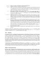
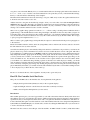
We use a build buffer to keep the pixel data relevant to the screen organized in a form convenient for moving into video
memory in mode X. However, in order to avoid having to move the data around a lot in the build buffer (or redraw
the whole screen each time we move the logical view window by one pixel), we break the maze world into 4x1 pixel
chunks using the mode X mapping illustrated in the previous section. The address of the logical view window in the
maze world is used to decide where to place the image planes within the build buffer, and moves around within the
build buffer as the logical window moves in the maze world, as shown in the figure below.
0 1 2 3
this address is in
the window for
planes 1, 2, and 3
this address is in
the window for
plane 0
logical view
window
0 1 2 3
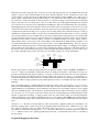
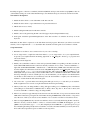
The mapping that we have described has a subtle detail: the address range used for the different planes within the
logical view window may not be the same. Consider the case shown above, in which show x & 3 == 1. As we
move the logical view window around in the maze world, we need to keep each address block at a fixed plane in the
build buffer (again to avoid having to copy data around). If we were to keep the planes in the order 0 to 3 and not put
any extra space between them, the image of plane 0 would in this case overlap with the image of plane 1 in the build
buffer. By reversing the order, we can avoid this problem (alternatively, we could have used a one-byte buffer zone
between consecutive planes).
The next problem is mapping the build buffer into the video memory. We use two buffers in video memory and map
into the non-displayed buffer, then change the VGA register to show the new screen. You can read about this doublebuffering technique in the code and see how it works. The complexity with regard to the plane mapping is that we
must map the build buffer planes, which are defined in terms of the maze world coordinates, into the video planes,
which are defined in terms of the screen coordinates. The picture below illustrates this problem. In general, a cyclic
shift of the planes suffices for the mapping.
0 1 2 3
0 1 2 3
video screen
memory
logical view
window
0 1 2 3
build buffer layout
0 1 2 3
build
buffer
video
memory
0
0
1
1
2
2
3
3
(a cyclic shift of planes)
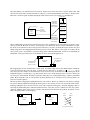
The next question is the size of the build buffer. If we can limit the size of the maze world, we can allocate a build
buffer large enough to hold any logical view window. If the window starts at pixel (0,0) in the maze world, plane 3 is
placed at the beginning of the build buffer. If the window occupies the lower right corner of the maze world, plane 0
is placed at the end of the build buffer. Such calculations are not particularly hard.
However, we do not want to restrict the size of the maze world, so we add a level of indirection and move the relative
offset of the logical view window within the build buffer as the logical view shifts within the maze world. The maze
world can thus be of almost arbitrary size, and is limited only by the size of the coordinate types (32-bit indices).
(show_x,show_y)
old logical
view window
old logical
view window
new logical
view window
(scr_x,scr_y)
new logical
view window
build buffer
before copy
build buffer
after copy
new img3 + address of
(scr_x,scr_y)
old img3 + address of
(show_x,show_y)
copies a contiguous
region of memory for
simplicity
The img3 and img3 off variables provide the additional level of indirection. At any point in time, adding the address
calculated from the logical view window coordinates (show x,show y) to the img3 pointer produces a pointer to the
start of plane 3 in the build buffer. However, the actual position of that plane in the build buffer may change over time.
Whenever a new logical view window setting is requested, the code checks whether all four planes of the new window
fall within the build buffer boundaries. If they do not, the window is repositioned within the build buffer in order to
make it fit. To minimize copying, the planes of the new window are centered within the build buffer. The figure at the
bottom of the previous page illustrates the process.
Finally, we add a memory fence to the build buffer to ensure that we didn’t screw up the copying calculations. Read
about it in the code.
The Checkpoint
The order presented here is only a suggestion, but we do strongly recommend that you read the code first, that you
tackle the parts one at a time rather than working on them all at once, that you commit working versions to your
repository as you get each part working, and that you start with the easier parts. You must do all of these things for the
first checkpoint. Other parts of the final MP are optional at the first checkpoint, and will not serve to make up points
for missing required functionality.
Write the vertical line drawing routine in modex.c. Everything but the function body is already in place for you (even
the function header!), and you can look at the horizontal line drawing routine right next to it, so this part should be an
easy place to start. The main difficulty is for you to understand both how mode X maps pixels and how the abstractions
in modex.c work, so try to read the code and documentation to the point that you feel you understand these things,
then try to write the function with the help of the examples.
Find the VGA documentation for the status bar. Doing so was part of PS2, and you can work together and discuss how
it should be done, but not trade code to do it.
Add the status bar to the game. It should be big enough to allow you to write a line of text with an extra pixel above
and below. How big is that? Read the code. Defined constants have been cleverly included to reduce the amount of
work for you (see IMAGE versus SCROLL dimensions in the code), but you will have to shift a couple of bits of the
existing code around here and there because of VGA constraints.
Write a text to graphics image generation routine in text.c. Given a string, it should produce a buffer that holds a
graphical image of the ASCII characters in the string. The height of the buffer is fixed. You may either (a) figure out
how much text fits on the status bar and produce a buffer of fixed-size, or (b) return the resulting image width. In either
case, the text must be centered on the bar, in case (a) by this routine, and in case (b) by the next routine. Don’t forget
to put a prototype and explanation into text.h.
Write a routine to put a graphic image, and in particular, the output of routine described in the previous paragraph, on
to the status bar.
Put the level number, number of fruits, and clock (using minutes and seconds since the level was started, as shown in
the demonstration version) on the status bar.
You will notice that the player is surrounded by black pixels and leaves a trail in the code provided to you, whereas the
player is drawn on top of the normal maze floor and does not leave a trail in the demo version of the game. This effect
is accomplished by a technique known as masking, in which a separate mask image is used to differentiate between
fully transparent and fully opaque pixels in the image of the player. The blocks for the mask have been provided to
you, but you must write a routine to use the mask to determine which pixels are copied from the player image to the
screen, and which are not. You should store the old values for those pixels written to the screen in a buffer, which
you can think of as a third block image holding a picture of the maze floor under the player. Finally, you should
write an undraw routine that takes the mask and the pixel values copied from the floor and puts them back into the
screen, effectively erasing the player image. By drawing the player just before showing the screen and erasing the
player immediately afterwards, you can then create the effect illustrated by the demo version while retaining freedom
to move the player as you like in the rest of the event loop.
Be sure to look ahead at the rest of the assignment. You may want to get an early start.
Final CP: Tux Controller Serial Port Device
This portion of the MP is due on the final due date. Your requirements in the game are:
• Display the elapsed level time (minutes.seconds) on the 7-segment displays.
• Up/down/left/right on the tux controller have the same affect as the keyboard’s keys.
• Make some VGA palette manipulations (see next section)
Introduction:
This machine problem gives you several opportunities to work with software that interacts directly with devices and
must adhere to the protocols specified by those devices. Similar problems arise when one must meet software interface
specifications, but you need experience with both in order to recognize the similarities and differences. The Tux Controller is that funny little game controller attached to each of the machines in the lab. It was designed and implemented
by Kevin Bassett and Mark Murphy, two students who took this class during the 2004-2005 school year, and went on
to work as lab assistants for the class.
The Tux Controller connects to the USB port of the lab machine. An FTDI “Virtual Com Port” (VCP) driver makes
the USB port appear to software as a standard (old fashioned) RS232 serial port. We can then set up QEMU so that one
of the emulated serial ports on the virtual machine maps to the emulated serial port connected to the Tux Controller.
Your tasks for checkpoint 2:
1. Enable the device driver to control the LEDs on the Tux controller
2. Enable the device driver to report when buttons are pressed and released
3. Handle device resets correctly
4. Enable reading the LED state from the Tux controller.
5. Enable control of the game using the Tux controller (support keyboard input simultaneously).
6. In the game, enable the up/down/left/right buttons on the Tux controller to do what the arrow keys do on the
keyboard.
Remember, the Tux driver is expected to work with ANY user-level program. This means you will not receive full
credit if you do not implement all ioctls described in this document even if the game does not make use of them.
Set up instructions:
1. Remember to use SVN or save a current version of your code as a backup.
2. You no longer need to compile the entire linux kernel, so you no longer need to boot your compiled kernel.
To prevent your compiled kernel from running, right click on “test debug.lnk” shortcut, go to properties and
remove the -kernel ...
bzImage from the target line.
3. Enable your test machine to make use of the serial port (named COM#) corresponding to the Tux controller. To
check which COM number the Tux controller is currently connected on: Go to Start -> Devices and Printers ->
right-click on FT232R USB UART -> Hardware tab -> USB Serial Port (COM#) where # should be less than
10. If it is higher, call a TA because it will not work with QEMU. Right click on “test debug.lnk” shortcut, go to
properties and add -serial COM# to the end of the target line. This connects the Windows COM# port to the
Linux ttyS0 serial port. Note: Only your test machine will be able to communicate with the Tux controller with
this setup. Although you can also add this option to your devel machine, you can only have one virtual machine
use the Tux at a time. Therefore, we recommend you use the devel machine to compile your code and the test
machine to load the kernel module and run the game.
4. Also remove the -S option from the end of the target line This option told qemu to wait until gdb was attached.
In this assignment we don’t need to start gdb until after the kernel is up and running.
5. When you first start your debug machine, a dialog will appear asking you for COM# Properties. The default
values (Bits per second should be = 9600, Data bits = 8, Parity = None, Stop bits = 1, Flow control = None) will
be correct. Click OK to continue booting your debug machine.
6. If there is no activity for approximately 2 hours, the Tux controllers will enter a low-power state and turn off the
LEDs. This is intended to prolong the life of the LEDs. Pressing the RESET button will return it to a responsive
state. Be aware of this if you sit down at a new machine or do not use the controller for more than two hours.
7. There is a bug in QEMU that may cause the test machine to freeze occasionally while using the Tux controllers.
When it is frozen, you will be unable to connect to or interact with it from GDB. If that happens, go to the
QEMU console (ctrl+alt+2), type i 0x3f8 (this will pull bytes from UART like in), press the up arrow to get
the command again and repeatedly enter it several times. Go back to the virtual terminal you were in (ctrl+alt+1).
If it is still locked, repeat the steps above until it becomes responsive.
Building the Driver:
The mp2/module directory contains a framework for the driver you will be implementing for the Tux controller. A
module is similar to a dynamically-loaded user-level library but instead of being used by an application it is used by
the kernel to extend functionality. Modules allow for drivers to be loaded without having to recompile (or even reboot)
the whole kernel. This simplifies the process of debugging as well. Modules can also be unloaded and a new version
loaded into the kernel assuming that nothing catastrophic happened that would crash the kernel. Your driver code, of
course, is running in the kernel, and bugs that are severe enough to crash the kernel are not impossible to produce.
The module directory uses a separate Makefile to compile a device driver module for use with Tux controller, thus
building a module is similar to building a user level program: Change directories into the module directory and type
make.
To load the module into the kernel, type sudo /sbin/insmod ./tuxctl.ko while in the module directory. A line
should print out saying the tuxctl line discipline has been registered. You can safely ignore the “module license
‘unspecified’ taints the kernel” message. 1
If you want to remove the module, issue the sudo /sbin/rmmod tuxctl command. This removes the module
from kernel space and should print a line stating the tuxctl line discipline was removed. You can use these commands
to install and remove the kernel module repeatedly during your development. If your module corrupts the kernel,
however, you may eventually crash the system and have to reboot. If all else fails, try rebooting the test machine and
then loading your module to see if it is really your latest code that is failing.
The module we have given you implements a tty line discipline. A line discipline is a driver that receives commands
from the tty or serial port driver. In other words, it acts as a middle man between the serial port and the code you
will implement to actually interpret the Tux controller commands. The code you will be implementing is in the
tuxctl-ioctl.c file. You may add anything you deem necessary to the header files to make your implementation
work. We also recommend you look at the mtcp.h file for a description of how the Tux controller works and some
predefined constants, and at the appendix at the end of this document.
Writing Your Driver:
You will write portions of both the device driver which communicates with the Tux controller and the user-level
application code to make use of the driver. On the driver side, you will need to add constants and definitions for
the abstracted bit format to the header file. These constants (located in tuxctl-ioctl.h) will shared by the kernel and
user-level code, ensuring that no inconsistencies arise. There is no user-level test harness for MP2. We advise you to
write a simple test program to test your driver outside the game. We suggest that you write a test program to test the
basic functionality (open, close, ioctls) before trying to make the game use the driver. We have provided input.c as
a starting point for your user-level testing. To compile input.c type make input. We will test your driver with our
own testing code, so be sure to test your driver’s functionality thoroughly and adhering strictly to the spec. For the
checkpoint, you must add the Tux controller functions (open, ioctls, close) to the input control in input.c and test it
by compiling the file by itself. You will need to include tuxctl-ioctl.h. Only once you have debugged your input
control completely as a stand alone program should you try it with the full game. To interface with the game you will
need to create a new thread to take input from the Tux controller (you must support keyboard input simultaneously.
Opening the Tux controller is fairly simple. You may use the following code as an example to open the serial port and
set the Tux controller line discipline:
fd = open("/dev/ttyS0", O RDWR | O NOCTTY);
int ldsic num = N MOUSE;
ioctl(fd, TIOCSETD, &ldisc num);
This code simply opens the tty port and sets the line discipline. You will want to add some error checking and whatever
else you see fit to make this work with your code.
What Your Driver Has To Do:
Your device driver transforms the protocol supported by the Tux controller into a simpler abstraction for use by user1 This
simply indicates that the module you have loaded has not been designated as GPL and therefore taints the kernel so don’t try to submit
any bug reports to Linus.
level programs such as the game. You must implement the following ioctls for your device abstraction:
TUX INIT Takes no arguments. Initializes any variables associated with the driver (see TUX READ LED) and
returns 0. Assume that any user-level code that interacts with your device will call this ioctl
before any others.
TUX SET LED The argument is a 32-bit integer of the following form: The low 16-bits specify a number whose
hexadecimal value is to be displayed on the 7-segment displays. The low 4 bits of the third byte
specifies which LED’s should be turned on. The low 4 bits of the highest byte (bits 27:24) specify
whether the corresponding decimal points should be turned on. This ioctl should return 0.
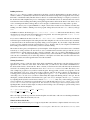
TUX BUTTONS Takes a pointer to a 32-bit integer. Returns -EINVAL error if this pointer is not valid. Otherwise,
sets the bits of the low byte corresponding to the currently pressed buttons, as shown:
7
right left down up c
b a
0
start
For full credit, use an interrupt-driven approach rather than polling.
Your changes to the device driver should be limited to the files tuxctl-ioctl.h and tuxctl-ioctl.c. The function tuxctl handle packet handles all packets received by the computer from the Tux controller. The function
tuxctl ioctl handles calls from user code (the game) to ioctl. You may add more ioctl calls, however the
required ioctls above must work as intended.
Tux Controller communication protocol:
The Tux controller protocol for interacting with the PC is described in mtcp.h, as you saw in PS2. Messages sent to
the Tux controller are of variable length, while messages sent to the computer are always three bytes in length of the
following general form:
Responses from the controller to the PC are always sent as three-byte packets of the following general form:
7
0
0
1 R4 R3 0 R2 R1 R0 0
1
7 data bits
1
1
7 data bits
2
The 5-bit vector R[4:0] in byte 0 represents an opcode. All possible opcodes are defined in mtcp.h The other three
bits in byte zero are fixed as indicated. Notice that bit 7 of each byte is fixed and used to frame the packets. This is a
feature of the packet format because the COM port emulation in the old Microsoft Virtual PC software that we used to
use was unreliable and occasionally lost bytes sent through it. The provided kernel patch includes code to detect this
behavior and avoids providing you with broken packets. See the code in tuxctl-ld.c for details.
The Tux controller supports many different commands, each of which is defined in mtcp.h. You are only required to
use a couple of them for this MP.
We recommend that you make use of MTCP BIOC ON and MTCP LED SET, in which case you must handle MTCP ACK
and MTCP BIOC EVENT. You must also handle MTCP RESET packets sent to the computer by attempting to restore the
controller state (value displayed on LEDs, button interrupt generation, etc.).
MTCP POLL This command consists of a single MTCP POLL byte (0xC2) sent to the controller: The response is a
three-byte packet with the following format:
7
0
0
1
0
0
0
1
0
0 0
1
X X X C B A S 1
1
X X X R D L
U 2
That is, the first byte will have the value MTCP POLL OK, the second and third will contain active-low
bit masks of which buttons are pressed; that is, a bit will be ‘0’ when the corresponding button is
pressed. The C, B, A, and START (S) buttons are in the second byte, and the right (R), down (D),
left (L), and up (U) bits are in the third. Bits marked as ‘X’ in the diagram are unused.
MTCP LED SET See mtcp.h for the definition of the LED SET bytes
Finally, a few important notes about the Tux controller:
For debugging purposes, when the controller receives an erroneous command, it locks up and displays 00P5 on the
seven-segment display. Pressing the reset button returns it to a usable state. This behavior can be disabled by sending
an MTCP DBG OFF command; after this is sent, an erroneous command will elicit an MTCP ERROR response.
Additionally, when the controller is reset, for example by pressing the reset button, it asynchronously sends an
MTCP RESET packet to the PC. Your code must detect this condition and re-initialize the controller to the same
state it was in before the reset. In order to accomplish this your code must internally keep track of the state of the
device.
Debugging the Tux Controller:
Debugging in kernel space is not as simple as debugging in user space. You made find it helpful to use printk()
from your driver module. printk() is like printf() for kernel mode.
For mor econhen the kernel loads the tuxctl module, it may load it anywhere it pleases in its address space. This means
GDB needs to know where the module was loaded before it can start debugging it. The object file for the tuxctl also
needs to be loaded into GDB so that the proper symbols can be resolved.
Once your debug machine loads, load the tuxctl module (see above). You now need to find out where in memory the
kernel loaded the module. Issue the command cat /proc/modules to print out the location of all modules currently
loaded in the kernel. You should see a line such as
tuxctl 6792 0 - Live 0xd0813000 (P)
at the top. 0xd0813000 is the address the module was loaded at. (It will probably be different for you). Back in
your devel machine, in the module directory, launch gdb with no arguments. Once in GDB, type add-symbol-file
./tuxctl.o ADDRESS where ADDRESS is the address that was printed out in for the module in your debug machine,
0xd0813000 in my case. GDB will then ask you to confirm. Type y and hit enter. Now you will need to connect
GDB to the remote machine by typing target remote 10.0.2.2:1234. You may now define breakpoints for your
driver and continue as normal.
Again, make use of the stand-alone input program in input.c before tackling the full game.
Final CP: VGA Palette Manipulations
The rest of the MP, which is also only due at the final due date, consists primarily of manipulating VGA palette colors
and making use of the event loop to control timing.
Find the VGA documentation for setting palette colors. As with the status bar, doing so was part of PS2. Write a
function that sets a palette color. Put the function in modex.c.
Make the player glow. The player’s center is a special color, so you just need to pick a color cycle and design it into
the event loop. Ticks range from 20 milliseconds down to about 5 ms; you can make the colors change in terms of
ticks or absolute time, as you prefer.
Make the maze walls and status bar change color with level. There are ten levels. Pick some colors. Make sure that
adjacent levels look different (you can reuse some colors if you want, but you can’t have just one). You can also make
them glow, change with the number of fruits, etc., but these last things aren’t required.
Create floating, semi-transparent text that lasts a few seconds when a player finds a fruit. For transparency, you can use
a linear interpolation of RGB values between the underlying color and white. You should take advantage of the fact
that you are only required to use one transparent color to simplify the problem. In particular, you can dedicate a region
of the palette to hold copies of the regular colors when viewed through the transparent color. The color you choose
should be based on the given demo program. You will need to work with the main game event loop in rtc thread in
mazegame.c in order to get the text to last for a few seconds.
Handin
Both the checkpoint and the final handin will require you to sit down with a TA in the lab to demonstrate your code
and to answer a few questions.
You may also complete any missed functionality from the Checkpoint 1 demo at the Checkpoint 2 demo to receive
half the credit on the points you missed.