1
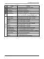
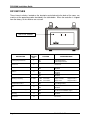
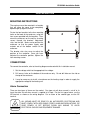
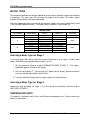
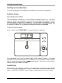
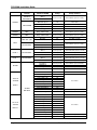
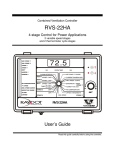
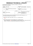
Combined Ventilation Controller
RVS-22HA
4-stage Control for Power Applications
2 variable speed stages
and 2 thermo/mister cycle stages
72.5
VAR STAGE 1
VAR STAGE 2
STAGE 3
A
STAGE 4
MIST
ROOM TEMP.
MIN
MAX
HEATER 1
HEATER 2
B
ALARM OFFSETS
HEAT 1
HEAT 2
RH COMPENSATION
T° CURVE
MIN. SPEED CURVE
DEFECTIVE PROBE
MIST
OFFSET / DIFF.
CURRENT RAMPING DAY
OFFSET / DIFF.
MIN. SPEED / CURVE
OFFSET / DIFF.
BANDWIDTH / TIMER
STAGE 1
HUMIDITY MIN / MAX
ON (SEC.)
TIMER OFF (MIN.)
STAGE 3
ALARM
LOCKED
SET POINT / T°CURVE
STAGE 4
DIFF.
RH COMPENSATION
DIFF.
OFFSET / BANDWIDTH
MIN. SPEED
SET
STAGE 2
RVS-22HA
Installation Guide
Read this guide carefully before installing the controller.
PRECAUTIONS
We strongly recommend connecting the controller to an alarm system, and installing
a supplementary natural ventilation system as well as a back-up thermostat on at
least one cooling stage. Refer to the wiring diagram enclosed with this installation
guide to connect the thermostat.
Inputs and outputs circuitry is protected against overload and overvoltage. However,
we recommend installing an additional protection device on the supply circuit as well
as an external relay on all ON-OFF stages to prolong the life of the controller.
To avoid exposing the controller to harmful gases or excessive humidity, it is
preferable to install it in a corridor.
The room temperature where the controller is located MUST ALWAYS REMAIN
BETWEEN 32° AND 104°F (0° AND 40°C).
DO NOT SPRAY WATER ON THE CONTROLLER.
FOR CUSTOMER USE
Enter below the serial number located
on the side of the controller and retain
this information for future reference.
Model number: RVS-22HA
Serial number:
________________
TABLE OF CONTENTS
FEATURES ......................................................................................................................2
CONTROL INTERFACE ..................................................................................................4
COVER.................................................................................................................................. 4
DIP SWITCHES..................................................................................................................... 6
INSTALLATION ...............................................................................................................7
MOUNTING INSTRUCTIONS................................................................................................ 7
CONNECTIONS .................................................................................................................... 7
Alarm Connection ............................................................................................................ 7
MOTOR TYPES .................................................................................................................... 8
Selecting a Motor Type for Stage 1.................................................................................. 8
Selecting a Motor Type for Stage 2.................................................................................. 8
TEMPERATURE UNITS ........................................................................................................ 8
TEMPERATURE PROBES.................................................................................................... 9
Connecting the Probes .................................................................................................... 9
Extending the Probes....................................................................................................... 9
Installing the Room Probes .............................................................................................. 9
Installing the Humidity Probe ......................................................................................... 10
Defective Probes............................................................................................................ 10
TROUBLESHOOTING GUIDE .......................................................................................11
TECHNICAL SPECIFICATIONS ....................................................................................14
FACTORY SETTINGS ...................................................................................................15
WIRING DIAGRAM ........................................................................................................17
NOTES ...........................................................................................................................18
RAYDOT Ventilation Control
Page 1
FEATURES
The RVS-22HA is a powerful environmental controller that can manage two variable ventilation
stages and two on/off ventilation/mist/heater stages. The “room temperature” is the temperature
averaged from 1 to 4 probe readings. Heaters follow either the room temperature or a zone
temperature, depending on user setup. A humidity probe may be used to lower the humidity
level by activating stage 1 or by deactivating the mist stage.
It is important to read both the RVS-22HA User’s Guide and the present Installation Guide. The
Installation Guide provides information on physical characteristics of the controller, mounting,
connections, probes, troubleshooting and technical specifications. The User’s Guide explains
the workings of the controller parameters.
RVS-22HA highlights:
Displays absolute temperatures for all stages
Temperature readings and high/low for both room and individual readings
Selectable 2.0°F (1.1°C) offset for all on/off stages
Optional humidity probe (reading and high/low) with relative humidity compensation
Alarms for high, low and critical temperatures; power failure alarms
Test mode
Set point and minimum ventilation curve, with 10 easily adjustable points
Temperature available in °C or °F units
Up to two heating stages (zoned or cascading)
De-icing on variable stage 2
Standard alarm output
CSA approved for both the United States and Canada
Control of air inlets with potentiometer feedback (must be used in combination with RV-F-1A
module)
Page 2
RAYDOT Ventilation Control
RVS-22HA Installation Guide
Here is a brief description of the RVS-22HA main features.
Digital display
A three-digit display provides a high level of accuracy, allowing the user to specify a temperature
to within one tenth of a degree (in Fahrenheit or Celsius units).
Pilot lights
Pilot lights indicating the status of outputs allow you to monitor the operation of the system from
a distance.
Minimum ventilation cycle
When ventilation is not required for cooling, the first stage fans can be operated either
continuously or intermittently to reduce the level of humidity and supply oxygen to the room.
Temperature and minimum ventilation speed curves
The controller can be set to automatically change the temperature set point and the minimum
ventilation speed over a given period of time in accordance with the user’s requirements by
specifying a temperature curve and a minimum ventilation speed curve with up to ten different
points each.
Choice of ten motor types
The variation in motor speed resulting from a change in voltage will depend on the make and
capacity of the motor. In order to achieve a high degree of compatibility between controller and
motor, the user can choose from ten different motor types, thus ensuring that the correct
voltages are supplied.
Humidity compensation
As humidity increases, the minimum speed of stage 1 fans increases proportionally to
compensate for the change.
Full speed fan start up
In order to overcome the inertia of the ventilation system components and de-ice the fan blades
in cold weather conditions, the controller supplies maximum voltage to the variable speed fans
during the four seconds that immediately follow start-ups.
Four independent temperature probe inputs
Up to four temperature probes can be connected to the controller in order to obtain a more
accurate reading of the average room temperature.
Overload and overvoltage protection
Inputs and outputs circuitry is protected against overload and overvoltage.
Test mode
A test mode allows the user to simulate temperature changes and verify controller performance.
RAYDOT Ventilation Control
Page 3
RVS-22HA Installation Guide
CONTROL INTERFACE
COVER
1
2
3
4
72.5
VAR STAGE 1
VAR STAGE 2
STAGE 3
A
13 pilot lights
STAGE 4
MIST
ROOM TEMP.
MIN
MAX
HEATER 1
HEATER 2
B
ALARM OFFSETS
HEAT 1
HEAT 2
RH COMPENSATION
T° CURVE
MIN. SPEED CURVE
DEFECTIVE PROBE
MIST
SET POINT / T°CURVE
OFFSET / DIFF.
CURRENT RAMPING DAY
OFFSET / DIFF.
MIN. SPEED / CURVE
OFFSET / DIFF.
BANDWIDTH / TIMER
STAGE 1
HUMIDITY MIN / MAX
ON (SEC.)
TIMER OFF (MIN.)
STAGE 3
ALARM
LOCKED
5
DIFF.
RH COMPENSATION
DIFF.
STAGE 4
OFFSET / BANDWIDTH
MIN. SPEED
SET
STAGE 2
RVS-22HA
Page 4
RAYDOT Ventilation Control
RVS-22HA Installation Guide
Item
Name
Function
Digital display
Displays the value of the parameter selected.
2
Parameter selection knob
Used to select a parameter.
3
Push button A
Used to access sub-parameters.
4
Push button B
Used to access sub-parameters.
5
Adjustment knob
Used to adjust the value of the selected parameter and to
access the TEST MODE (for an explanation on the test
mode, see the footnote in the Factory Settings section).
Variable stage 1
Lights up when the fan variable stage 1 is activated.
Variable stage 2
Lights up when the fan variable stage 2 is activated.
Stage 3
Lights up when stage 3 is activated.
Stage 4
Lights up when stage 4 is activated.
Mist
Turns on when the mister cycle stage is activated.
Heater 1
Lights up when heater 1 is activated.
Heater 2
Lights up when heater 2 is activated.
RH compensation
Turns on when compensating for relative humidity.
Temperature curve
Is on when the temperature curve is activated.
Minimum speed curve
Is on when the minimum speed curve (stage 1) is activated.
Defective probe
Turns on when a probe is defective.
Alarm
Lights up to signal an alarm.
Locked
Is on when parameter settings are locked.
13 pilot lights
1
RAYDOT Ventilation Control
Page 5
RVS-22HA Installation Guide
DIP SWITCHES
These internal switches, located on the electronic card attached to the back of the cover, are
used to set the operating modes described in the table below. When the controller is shipped
from the factory, all the switches are set to off.
The 12 DIP switches
DESCRIPTION
DIP
SWITCH
NO.
Locking the parameters
1
Reserved
2
Probe 2
3
Probe 3
4
Probe 4
5
Cooling or heating
6 and 7
Temperature heater
8
Mist
9
Offset on ventilation stages
10
De-Icing
11
Reserved
12
Page 6
POSITION
ON
OFF
DIP ON
DIP ON
DIP ON
1 2 3 4
5
9
6 7 8
11 12
OPERATING MODE
Locked parameters
Unlocked parameters
Reserved
ON
OFF
ON
OFF
ON
OFF
6: OFF and 7: ON or OFF
6: ON and 7: ON
6: ON and 7: OFF
ON
OFF
ON
OFF
ON
OFF
ON
OFF
Enabled
Disabled
Enabled
Disabled
Enabled
Disabled
Stage 3 Fan
Stage 4 Fan
Stage 3 Heater
Stage 4 Heater
Stage 3 Fan
Stage 4 Heater
Zoned Heaters
Cascading Heaters
Enabled
Disabled
2.0°F(1.1°C) offset on ventilation stages
No offset on ventilation stages
Enabled
Disabled
Reserved
RAYDOT Ventilation Control
RVS-22HA Installation Guide
INSTALLATION
MOUNTING INSTRUCTIONS
The enclosure must be mounted in a location
that will allow the cover to be completely
opened right up against the wall.
Fasten the four brackets to the four mounting
holes on the back of the enclosure, using the
four screws provided with the brackets. Then
mount the enclosure on the wall by inserting
screws through the brackets’ adjustment
slots, into the wall. Make sure to position the
enclosure so that the power supply cord
extends out of the bottom section of the
enclosure.
The bracket slots also serve to adjust the
position of the controller. Once you have
adjusted the controller position, tighten the
four mounting screws.
CONNECTIONS
To connect the controller, refer to the wiring diagram enclosed with this installation manual.
1. Set the voltage switch to the appropriate line voltage.
2. Drill access holes on the bottom of the enclosure only. Do not drill holes on the side or
the top of the enclosure.
3. It may be necessary to install a transformer on the heating stage in order to supply the
appropriate voltage to the heating unit.
Alarm Connection
There are two types of alarms on the market. One type sets off when current is cut off at its
input; the other sets off when current is supplied at its input. For the first type of alarm, use the
NO terminal as shown on the wiring diagram. For an alarm of the second type, use the NC
terminal.
WARNING
ALL WIRING MUST BE DONE BY AN AUTHORIZED ELECTRICIAN AND
MUST COMPLY WITH APPLICABLE CODES, LAWS AND REGULATIONS. BE
SURE POWER IS OFF BEFORE DOING ANY WIRING TO AVOID
ELECTRICAL SHOCKS AND EQUIPMENT DAMAGE.
RAYDOT Ventilation Control
Page 7
RVS-22HA Installation Guide
MOTOR TYPES
The relationship between the voltage supplied to a motor and its operating speed is described by
a motor type. This type varies with the make and capacity of the motor. The various motors
available in the industry have been represented.
Select the appropriate type to ensure that the controller supplies the correct voltage to the stage
1 and 2 variable speed fan motors. The factory default selection is type number 10.
MOTOR TYPES
TYPE NUMBER
BRAND NAME
MODEL
DIAMETER
VOLTAGE
1 to 8
Other
Val-Co
Val-Co
Val-Co
Val-Co
Val-Co
Val-Co
Val-Co
Val-Co
—
FW08W120MSA
FW10W130MSA
PM12^140MPA
PM16^140MPA
PM21^140MPA
PM21^190LPA
PM24^210MPA
PM36^280M*A
—
8”
10”
12”
16”
21”, 3 blades
21”, 4 blades
24”
36”
—
9
10
230 V
230 V
Selecting a Motor Type for Stage 1
In the motor types table above, locate the make and capacity of your stage 1 variable speed
motors and note the corresponding type number (1 to 10).
1. Set the parameter selection knob to BANDWIDTH/TIMER (STAGE 1).
bandwidth appears flashing on the display.
The stage 1
2. Press the push-button . The message “tyP” appears on the display, alternating with the
currently selected type number, which flashes.
3. Using the adjustment knob, adjust the type number to the desired value.
Selecting a Motor Type for Stage 2
Repeat the steps described for stage 1, this time setting the parameter selection knob to
MIN. SPEED (STAGE 2).
TEMPERATURE UNITS
This product is available in both Celsius and Fahrenheit temperature units. Please contact your
dealer for more details.
Page 8
RAYDOT Ventilation Control
RVS-22HA Installation Guide
TEMPERATURE PROBES
Connecting the Probes
The controller is supplied with one room probe connected to terminal # 1.
CAUTION
The probes operate at low voltage and are isolated from the supply. Be sure that
probe cables remain isolated from all high voltage sources. In particular, do not
route the probe cables through the same electrical conduits as other cables. Do
not run probe cables next to other power cables. If crossing over other cables,
cross at 90°. Connect the probe shield to the power supply ground terminal.
Switches are used to activate or deactivate the additional probes connected to the controller.
Activate each additional probe by setting the appropriate switch to on.
–
–
–
Switch # 3 activates the probe connected to input # 2;
Switch # 4 activates the probe connected to input # 3;
Switch # 5 activates the probe connected to input # 4.
Extending the Probes
Each probe can be extended up to 500 feet (150 meters). To extend a probe:
1. Use a shielded cable of an outside diameter ranging between 0.245 and 0.260 in. (6.22
and 6.60 mm) to ensure the cable entry is liquid-tight. Cable size should not be under 18
AWG.
2. It is preferable to solder the cable joints (to ensure a proper contact between the two
cables) and to solder the shields.
Installing the Room Probes
The building may be separated in two heating zones. Depending on how many inside probes are
activated, the zones will be divided differently.
PROBES CONTROLLING HEAT ZONES
Activated
Probes
Probe(s) Controlling
Zone A
Probe(s) Controlling
Zone B
ROOM TEMP. averaged from
which probe reading(s)
1
1
1
1
1,2
1
2
1,2
1,3
1
3
1,3
1,4
1
4
1,4
1,2,3
1,2
3
1,2,3
1,2,4
1,2
4
1,2,4
1,3,4
1
3,4
1,3,4
1,2,3,4
1,2
3,4
1,2,3,4
RAYDOT Ventilation Control
Page 9
RVS-22HA Installation Guide
Installing the Humidity Probe
Install the humidity probe in the middle of the controlled area, where there is good airflow.
Defective Probes
Room Temperature Probes
If an activated probe is defective or missing, the defective probe pilot light turns on. The display
shows the value of the temperature measured by the remaining room probe(s), and the
controller operates according to this temperature. If all room probes are defective or missing,
the screen will display “P Lo” when the parameter selection knob is set to ROOM TEMP., and
the controller will operate as if all temperature readings were equal to the Set Point.
To identify the defective probe:
Set the selection knob to ROOM TEMP. The room temperature is displayed.
A
MIN
ROOM TEMP.
MAX
B
SET
Press push-button A or B until the screen displays “Pr#” (Probe # [number]). If the probe
connected to the corresponding terminal is not defective, the screen displays “Pr#” alternating
with the temperature measured by the corresponding probe. Otherwise, the letter displays
“Pr#” alternating with “Pr#Lo” or “Pr#Hi”.
Humidity Probe
If the humidity probe is defective or if there is no humidity probe, the defective probe pilot light
does not turn on, but the display shows the letter “P Lo” or “P Hi” when the parameter selection
knob is set to STAGE 1 HUMIDITY (refer to “Stage 1 Humidity Readout” in the User’s Guide).
Page 10
RAYDOT Ventilation Control
RVS-22HA Installation Guide
TROUBLESHOOTING GUIDE
PROBLEM
There is no display.
CAUSE
SOLUTION
The circuit breaker on the
service panel is off or tripped.
Reset the circuit breaker.
The wiring is incorrect.
Correct the wiring.
The input fuse is open.
Replace the fuse.
The voltage selector switch is in
the wrong position.
Set the switch to the correct position.
The display board interconnect
cable is not properly plugged
into the power supply board.
Be sure the cable is firmly plugged in.
All activated probes are
improperly connected.
Make the correct room probe connection.
All activated probes are
defective.
Refer to “Defective Probes”.
The defective probe pilot
light is on.
One or more probes are
defective.
Refer to “Defective Probes”.
The display shows
sudden variations in the
room temperature.
A variation in resistance is
induced on a probe.
Be sure the probes are dry. Locate them
away from drafts and sources of radiant
heating.
There is electrical noise near a
probe cable.
Isolate the probe cables from all high
voltage sources. Do not route probe
cables and other power cables through
the same electrical knockout. Do not run
probe cables next to other power cables.
When crossing other power cables, cross
at 90°.
The wiring is incorrect.
Be sure that each variable speed fan is
properly connected to the corresponding
VARIABLE STG1 & STG2 terminals.
Each fan requires two wires to be
connected.
The stage 1 and 2 fuse is
blown.
Replace the fuse.
The minimum speed is too low.
Adjust the minimum speed to a higher
value.
The fan motor is defective.
Check if the motor is defective by
connecting it to an alternate power supply.
If it still is not operating, replace the motor.
The display shows “P Lo”
or “P Hi” when the
parameter selection knob
is set to ROOM TEMP.
The stage 1 or 2 variable
speed fan is not running.
RAYDOT Ventilation Control
Page 11
RVS-22HA Installation Guide
PROBLEM
The stage 1 or 2 variable
speed fan runs
continuously at full speed.
The stage 1 or 2 variable
speed fan runs erratically.
CAUSE
The wiring is incorrect.
The ambient temperature is
above the set point +
bandwidth.
The selected motor type is
inappropriate
The bandwidth is too small.
The stage 1 on time or off time
is too short.
A variation in resistance
induced on a room probe
causes this probe to measure
sudden variations in the room
temperature.
Electrical noise near a room
probe cable causes this probe
to measure sudden variations in
the room temperature.
Stage power are not in phase
with line power.
The stage 1 variable
speed fan runs
continuously when the
room temperature is
below the room set point
or when the controller
operates in minimum
ventilation cycle.
Stage 3 (fan, heater 2 or
mist),
or
stage 4 (fan, heater 1 or
mist)
is not functioning
properly.
The mist is not operating
as desired.
Page 12
The stage 1 off time is set to
zero.
The wiring is incorrect.
Humidity compensation is
activated and relative humidity
exceeds the humidity set point.
The wiring is incorrect.
The fan motor, heater or mist is
defective.
The controller is defective.
The mist on time and off time
were incorrectly adjusted.
SOLUTION
Fix the wiring.
Adjust the set point or bandwidth to the
desired value.
Select an appropriate motor type. Refer
to “Motor Types”.
Adjust the bandwidth to a higher value.
Adjust the stage 1 on time or off time to a
higher value.
Be sure the room probes are dry. Locate
them away from drafts and sources of
radiant heating.
Isolate the room probe cables from all
high voltage sources. Do not route probe
cables and other power cables through
the same electrical knockout. Do not run
probe cables next to other power cables.
When crossing other cables, cross at 90°.
Be sure that the stage power and line
power are in phase.
Set the stage 1 off time to a value other
than zero.
Be sure that two wires connect the stage 1
fan to the corresponding VARIABLE STG1
terminal.
Adjust the humidity set point or deactivate
compensation, as required.
Be sure that two wires connect each stage
to the corresponding terminal.
Check if the motor, heater or mist is
defective by connecting it to an alternate
power supply. If it still is not operating,
replace the motor or heater.
Listen to check if there is a clicking sound
when the stage or heater-mist pilot light
turns on. If there is no clicking sound,
your controller needs repair.
The mist on time is in seconds, and its off
time is in minutes. Adjust the mist on time
and off time correctly.
RAYDOT Ventilation Control
RVS-22HA Installation Guide
PROBLEM
The alarm doesn’t work
properly.
CAUSE
The alarm’s fuse is blown.
The wiring is incorrect.
The alarm is defective.
The controller is defective.
RAYDOT Ventilation Control
SOLUTION
Replace the fuse.
Correct the wiring. Refer to “Alarm
Connection”.
Verify if the alarm unit is defective by
connecting it to an alternate power supply.
Replace the alarm unit if it still is not
operating.
Listen to check if there is a clicking sound
when the alarm pilot light turns on. If
there is not clicking sound, contact your
distributor to have the controller repaired.
Page 13
RVS-22HA Installation Guide
TECHNICAL SPECIFICATIONS
DESCRIPTION
Page 14
VALUE
Input power
10 W
Power source (line)
115/230 VAC, -20%, +10%, 50/60 Hz
Power fuse
0.125 A @ 250 V, slow blow, 5 X 20 mm
Stages 3 and 4
10 A @ 125/250 VAC
1 HP @ 250 VAC
½ HP @ 125 VAC
Stage 1 and stage 2
10 A @ 115/230 VAC
Minimal charge: 25 mA @ 50/60 Hz
Alarm relay
1 A @ 30 VDC
Stage 1 and stage 2 power source
115/230 VAC, -20%, +10%, 50/60 Hz
(same power as line power)
Stage 1 and stage 2 fuse
15 A @ 250 VAC, slow blow
Storage temperature
-4°F to 130°F (-20°C to 55°C)
Operating temperature
32°F to 120°F (0°C to 50°C)
Temperature range – inside probes
-6.0°F to 168.6°F (-21.1°C to 75.9°C)
Weight
5.2 lbs. (2.36 kg)
Dimensions
11” X 7” X 6” (27.9 X 17.8 X 15.2 cm)
RAYDOT Ventilation Control
RVS-22HA Installation Guide
FACTORY SETTINGS
ROOM
TEMP.
Position
Parameter A↑
↑ B↓
↓
Factory
Setting
ROOM TEMP.
MIN./MAX.
Room Temp. Readout
Lo
Hi
Probe 1 Readout
Probe 1 Lo
Probe 1 Hi
Probe 2 Readout
Probe 2 Lo
Probe 2 Hi
Probe 3 Readout
Probe 3 Lo
Probe 3 Hi
Probe 4 Readout
Probe 4 Lo
Probe 4 Hi
Test Mode*
Software Version
—
—
—
—
—
—
—
—
—
—
—
—
—
—
—
OFF
2
SET POINT/
T°CURVE
Set Point
Adjust Day
Adjust Temperature
75.0°F (24.0°C)
—
—
-40.0 to 100.0°F (-40.0 to 40.0°C)
1 to 255
-40.0 to 100.0°F (-40.0 to 40.0°C)
CURRENT
RAMPING DAY
Current Day
Adjust Current Day
OFF
OFF, 1 to 255
MIN. SPEED/
CURVE
Minimum Speed
Adjust Day
Adjust Minimum Speed
40
—
—
12 to 100%
OFF, 1 to 255
12 to 100%
Bandwidth
Min. Ventilation On Time
Min. Ventilation Off Time
Motor Type
2.0°F (1.0°C)
15
0
10
0.5 to 20.0°F (0.3 to 11.0°C)
BANDWIDTH/
TIMER
HUMIDITY
MIN./MAX.
Readout
Lo
Hi
—
—
—
10 to 90 RH%
R.H.
COMPENSATION
Compensation Option
Humidity Set Point
R.H. Speed Compensation
OFF
65
50
ON/OFF
10 to 90 RH%
0 to 100%
SET POINT
STAGE 1
Range of Values
-6.0 to 168.6°F (-21.1 to 75.9°C)
2
0 to 900 seconds
1 to 10
* The Test Mode simulates a temperature reading, allowing the user to test the control’s reaction at a given
temperature.
To access the Test Mode, the user must position the parameter selection knob to ROOM TEMP. and press pushbutton A or B until “tESt” appears alternating with “OFF” on the display. To activate the TEST MODE, the user must
turn the SET knob back and forth; “tESt” will briefly appear on the display, followed by the default simulation
temperature. Using the SET knob, the user may modify this default simulation value – which is the ROOM TEMP. –
by 0.1° increments, and specify any temperature ranging from -6.0°F to 168.6°F (-21.1°C to 75.9°C).
To deactivate the Test Mode, the user must move the SET knob back and forth; “tESt” will appear alternating with
“OFF” on the display. Or, if the user does not turn a knob or a push a button for five minutes, the control will
deactivate the Test Mode automatically.
RAYDOT Ventilation Control
Page 15
RVS-22HA Installation Guide
Position
Parameter A↑
↑ B↓
↓
Factory
Setting
Range of Values
OFFSET/
BANDWIDTH
Offset
Bandwidth
2.0°F (1.0°C)
0.5 to 20.0°F (0.3 to 11.0°C)
MIN. SPEED
Minimum Speed
De-icing Cycle Time
De-icing On Time
Motor Type
40
1
0
10
12 to 100%
1 to 720 minutes
0 to 900 seconds
1 to 10
STAGE 4
DIFF.
Stage 4 Differential
2.0°F (1.0°C)
0.5 to 20.0°F (0.3 to 11.0°C)
STAGE 3
DIFF.
Stage 3 Differential
2.0°F (1.0°C)
0.5 to 20.0°F (0.3 to 11.0°C)
TIMER ON (SEC.)
TIMER OFF (MIN.)
On Time
Off Time
60
1
0 to 900 seconds
0 to 20 minutes
OFFSET/DIFF.
Offset
Differential
Humidity Turn Off
8.0°F (7.0°C)
2.0°F (1.0°C)
75
STAGE 2
MIST
0.5 to 20.0°F (0.3 to 11.0°C)
40 to 90 RH%, OFF
HEAT 2
OFFSET/DIFF.
Offset
Differential
Max. Diff. Prot. Bet. Zones
3.0°F (3.0°C)
2.0°F (1.0°C)
7.5°F (4.2°C)
-10.0 to 20.0°F (-5.5 to 11.0°C)
0.5 to 20.0°F (0.3 to 11.0°C)
5.0 to 40.0°F (3.0 to 22.0°C), OFF
HEAT 1
OFFSET/DIFF.
Offset
Differential
3.0°F (3.0°C)
2.0°F (1.0°C)
-10.0 to 20.0°F (-5.5 to 11.0°C)
0.5 to 20.0°F (0.3 to 11.0°C)
Low Offset
High Offset
Critical High Alarm
Alarm Individual/All
10.0°F (6.0°C)
12.0°F (7.0°C)
95.0°F (30.0°C)
ind.
0.5 to 40.0°F (0.3 to 20.0°C)
0.5 to 40.0°F (0.3 to 22.0°C)
-40.0 to 120.0°F (-40.0 to 50.0°C)
ind./ALL
Inlet 1
Inlet 1 Step 0
Inlet 1 Step 1 Lo
Inlet 1 Step 1 Hi
Inlet 1 Step 2 Lo
Inlet 1 Step 2 Hi
Inlet 1 Step 3
Inlet 1 Step 4
Inlet 1 Over Open
Inlet 1 Over Bandwidth
Inlet 1 Drop
OFF
5
10
25
50
60
75
90
100
5.0°F (3.0°C)
OFF
ON/OFF
Inlet 2
Inlet 2 Step 0
Inlet 2 Step 1 Lo
Inlet 2 Step 1 Hi
Inlet 2 Step 2 Lo
Inlet 2 Step 2 Hi
Inlet 2 Step 3
Inlet 2 Step 4
Inlet 2 Over Open
Inlet 2 Over Bandwidth
Inlet 2 Drop
OFF
5
10
25
50
60
75
90
100
ALARM
RV-F-1A
OPTION
INLET 1
ALARM
OFFSETS
RV-F-1A
OPTION
INLET 2
Page 16
5.0°F (3.0°C)
OFF
0 to 100%
0.5 to 20.0°F (0.3 to 11.0°C)
ON/OFF
ON/OFF
0 to 100%
0.5 to 20.0°F (0.3 to 11.0°C)
ON/OFF
RAYDOT Ventilation Control
117
721
For routing cable into the controller housing, drill holes at the bottom of the housing.
Do not drill holes on the sides of the housing.
W
Required clearance: 12” above controller housing, to allow for cover opening.
Provide surge protection (to include protection from lightning) from power supply to control and from
control to output extended probe. Consult a certified electrician for specific recommendations.
Set the voltage switch to the appropriate voltage.
Line power and variable fan power must be in phase.
FAN STAGE 4 FAN STAGE 3
HEATER 1
HEATER 2
MIST
MIST
ALARM
SUPPLY
SET THE VOLTAGE
SWITCH TO THE APPROPRIATE
VOLTAGE.
VARIABLE
STG 1& 2
230V
LINE VOLTAGE
SELECTOR
POWER
115/230
LINE
L2/N
L1
GND
ON/OFF
L2/N
WARNING!!!
connect probe
shield(s) to GND
terminal of
power supply
L1
BLACK
BROWN
RED
WIRING DIAGRAM
RH VALCO
(Humidity Probe)
We recommend separate circuit breakers for each output stage.
IN
TEMPERATURE 4
S1
O
P
T
RMV-2
MODULE
Installation of a good quality alarm system is strongly advised to warn of power failures and high / low
temperatures.
S2
TEMPERATURE 3
Use shield for shielding purpose only. Connect the shield to the gnd of power supply.
X Y/A Z/B
TEMPERATURE 2
ALARM
G
1
2
G
3
4
G
5 / HUM
PWR
NO
C
NC
TEMPERATURE 1
PROBES
RAYDOT Ventilation Control
WIRING DIAGRAM RVS-22HA
GND
L2/N
(NOT INCLUDED)
BACKUP THERMOSTAT
FOR STAGE 1
L2/N
FOR
SELECTION
OF OUTPUTS
SEE USER’S
GUIDE
L2/N
FAN STAGE 4 / HEATER 1 / MIST
MAX. OUTPUT 10 AMP.
FAN STAGE 1
MAX. OUTPUT 10 AMP.
L1
L1
L2/N
FAN STAGE 3 / HEATER 2 / MIST
MAX. OUTPUT 10 AMP.
FAN STAGE 2
MAX. OUTPUT 10 AMP.
L1
Page 17
REV. A04
RVS-22HA Installation Guide
L1
RVS-22HA Installation Guide
NOTES
Page 18
RAYDOT Ventilation Control
RVS-22HA Installation Guide
RAYDOT Ventilation Control
Page 19
RVS-22HA Installation Guide
Page 20
RAYDOT Ventilation Control
MAY22 v1.3