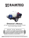
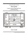
1
For DENSO Authorized
ECD Service Dealer Only
Diesel Injection Pump
No. E-03-03
SERVICE MANUAL
Common Rail System for HINO
J08C/J05C Type Engine
Operation
June, 2003
00400024
-1
GENERAL
The ECD-U2 was designed for electronic control of injection quantity, injection timing and injection pressure to obtain optimal operational control.
Features
Lower exhaust gas and higher output due to high pressure injection in all usage ranges.
Reduction in noise and exhaust gas due to injection rate control.
Improved performance due to increased flexibility in the injection timing setting.
Independent control of injection pressure in response to engine speed and load.
Main Elements
Manufacturer
Hino Motor, Ltd.
Total
Maximum Output
Cylinder
Displacement
(PS/rpm)
Configuration
(cc)
Vehicle
Model
Engine
Model
HR1J
J08C
Straight 6
7,961
RX4JFE
J05C
Straight 4
5,307
J-N: 205/2,900
J-V: 220/2,900
175/2,900
Main Components Part Number
No.
1
1-1
2
3
3-1
3-2
3-3
Description
Supply pump
Cylinder recognition
sensor
Injector
Rail
Rail pressure sensor
Pressure limiter
Flow damper
HR1J (J08C-UC)
DENSO P/N
HINO P/N
094000-0183 22730-1042A
RX4JFE (J05C-TG)
DENSO P/N
HINO P/N
094000-0193 22730-1072A
029600-0580 89411-1290A1 029600-0580 89411-1290A1
095000-0174 23910-10033C 095000-0174 23910-10033C
095440-0243 22760-1100C 095440-0171 22760-1041C
499000-4441
499000-4441
095420-0060
095420-0060
095400-0150
095400-0150
0
1. Outline
1.1 System Outline
This system also provides the following functions:
A self-diagnosis and alarm function using computer to diagnose the system s major
components and alert the driver in the event of a problem.
A fail-safe function to stop the engine, depending upon the location of the problem.
A backup function to change the fuel regulation method, thus enabling the vehicle to
continue operation.
1.2 System Configuration
Divided by function, the system can be classified according to the fuel system and the control
system.
[1] Fuel System
High-pressure fuel that is generated by the supply pump is distributed to the cylinders using a rail.
Electromagnetic valves in the injectors then open and close the nozzle needle valve to control
the start and end of fuel injection.
[2] Control System
Based on the signals received from various sensors mounted on the engine and the vehicle, the
ECU controls current timing and the duration in which the current is applied to the injectors, thus
ensuring an optimal amount of fuel is injected at an optimal time.
The control system can be broadly classified according to the following electronic components:
sensors, computers, and actuators.
1
[3] System Configuration (1)
2
[4] System Configuration (2)
3
1.3 Construction and Operation of the System
The rail system is comprised of a supply pump, a rail, and injectors, and also includes an ECU
and sensors to regulate those components.
The supply pump generates the internal fuel pressure in the rail. Fuel pressure is regulated by
the quantity of fuel discharged by the supply pump. In turn, the fuel discharge quantity is regulated by electronic signals from the ECU that turn the PCVs (pump control valves) ON and OFF.
Upon receiving fuel pressurized by the supply pump, the rail distributes the fuel to the cylinders.
The pressurized fuel is detected by the rail pressure sensor (installed in the rail) and undergoes
feedback control so that actual pressure will match the command pressure (designated according to the engine speed and load).
Pressurized fuel in the rail passes through the injection pipes that lead to the cylinders, and applies
pressure to the injector nozzles and the control chamber.
The injector regulates injection quantity and timing by turning the TWV (two-way valve) ON and OFF.
When the TWV is ON (current applied), the fuel circuit switches over, causing the high-pressure
fuel in the control chamber to flow out via the orifice. As a result, the force of the high-pressure
fuel at the nozzle valve opening causes the needle valve to lift, thus starting the injection of fuel.
When the TWV is turned OFF (current not applied), the fuel circuit switches over so that highpressure fuel, traveling via the orifice, is introduced to the control chamber. As a result, the needle valve lowers, thus ending the injection of fuel.
Thus, through electronic control, the timing of the current applied to the TWV determines the
injection timing, and the duration in which current is applied to the TWV determines the injection
quantity.
4
1.4 Comparison to Conventional Pump
5
2. Construction and Operation of Components
2.1 Supply Pump
[1] Outline
The function of the supply pump is to regulate the fuel discharge volume, thus generating internal
fuel pressure in the rail.
[2] Construction
The supply pump consists of a feed pump, similar to that of the conventional in-line pump, and
the PCVs (pump control valves), provided at each cylinder, to regulate the fuel discharge volume.
The supply pump uses a three-lobe cam or two-lobe cam reducing the number of pump cylinders to one-third or one-second of the engine cylinders (e.g. a two-cylinder pump for a six-cylinder engine or for a four-cylinder engine). Furthermore, a smooth and stable rail pressure is
obtained because the rate at which fuel is pumped to the rail is the same as the injection rate.
6
[3] Operation
A: The PCV remains open during the plunger s downward stroke, allowing low-pressure fuel to
be drawn into the plunger chamber by way of the PCV.
B: If the valve remains open because current is not applied to the PCV, even after the plunger
begins its upward stroke, the fuel that was drawn in returns via the PCV, without being pressurized.
C: When current is applied to the PCV in order to close the valve at the timing that accommodates the required discharge volume, the return passage closes, causing pressure in the
plunger chamber to rise. The fuel then passes through the delivery valve (check valve) to the
rail. As a result, an amount of fuel that corresponding to the plunger lift after the PCV closes
becomes the discharge volume, and varying the timing of the PCV closure (plunger prestroke) varies the discharge volume, thus regulating rail pressure.
A : After surpassing the maximum cam lift, the plunger begins its downward stroke, causing
pressure in the plunger chamber to decrease. At this time, the delivery valve closes, thus
stopping the pumping of the fuel. In addition, because current to the PCV valve is cut off, the
PCV opens, allowing low-pressure fuel to be drawn into the plunger chamber. Thus, the
pump assumes condition
.
7
[4] PCV (pump control valve)
The PCV regulates the volume of fuel discharged by the supply pump in order to regulate rail
pressure. The volume of fuel discharged by the supply pump to the rail is determined by the
time at which current is applied to the PCV.
[5] Trochoid Type Feed Pump
The feed pump, which is housed in the supply pump, draws fuel up from the tank and delivers
it to the chamber via the fuel filter. The feed pump rotor is driven by the camshaft.
The rotation of the camshaft causes the outer and inner rotors to rotate. At this time, the suction
port side pump chamber volume (the space surrounded by the outer and inner rotors) increases
gradually, causing the fuel entering from the fuel inlet to be drawn into the pump chamber via
the suction port. Along with the rotation of the rotor, the fuel that has been drawn in moves towards the discharge port and is discharged. The discharged fuel travels via the fuel outlet and
is fed into the supply pump body.
[6] Coupling
The coupling is an intermediary device that transmits
the engine driving torque to the supply pump camshaft.
8
2.2 Rail
[1] Construction
The functionof the rail is to distribute the high-pressure fuel pressurized by the supply pump to
each cylinder injector.
The rail pressure sensor, flow damper, and pressure limiter are mounted on the rail.
A fuel injection pipe is attached to the flow damper to deliver high-pressure fuel to the injector.
The pressure limiter piping is routed back to the fuel tank.
[2] Flow Damper
The flow damper reduces pressure pulsation in the
high-pressure pipe, thus delivering fuel to the injectors
at a stable pressure. Furthermore, in the event an excessive flow of fuel, the flow damper shuts off the fuel
passage, thus preventing the abnormal fuel flow.
When abnormal amount of fuel flows the high-pressure is applied to the piston. As shown in the illustration, this causes the piston and ball to move right, until
the ball reaches the seat and closes the fuel passage.
[3] Pressure Limiter
The function of the pressure limiter is to dispel abnormally
high pressure by opening its valve to release pressure.
The pressure limiter operates (opens the valve) when
rail pressure reaches approximately 140MPa.
Then, when the pressure decreases to approximately
30MPa, the pressure limiter resumes (closes the valve)
its function to maintain pressure.
NOTE:
Do not attempt to remove or to reinstall the flow damper, pressure limiter, and the rail
pressure sensor.
9
[4] Rail Pressure Sensor
The rail, the rail pressure sensor is mounted on the rail and detects the fuel pressure. It is a
semi-conductor type of pressure sensor that utilizes the properties of silicon to change its electrical resistance when pressure is applied.
2.3 Injector
[1] Outline
The function of the injector is to inject high-pressure fuel from the rail into the engine combustion chamber at the proper timing, quantity, ratio, and atomization, in accordance with signals
from the ECU.
The TWV (two-way solenoid valve) regulates pressure in the control chamber in order to control
the beginning and end of injection.
The orifice restrains the opening speed of the nozzle valve to regulate the injection ratio.
The command piston transmits pressure from the control chamber to the nozzle needle valve.
The nozzle atomizes the fuel.
10
[2] Construction
The injector consists of the nozzle portion (similar to that of the conventional type), the orifice
(which regulates the injection ratio), the command piston, and the two-way solenoid valve
(TWV).
11
[3] Operation
The TWV portion of the injector consists of two valves, an inner valve (fixed) and an outer valve
(movable). Both valves are precision-fitted on the same axis. The valves respectively form inner
and outer seats, and either of the seats opens selectively depending upon whether the TWV is
ON or OFF.
a. No Injection
When no current is applied to the solenoid, the valve spring and hydraulic pressure forces
push the outer valve downward, causing the outer seat to remain closed. Because the rail
high pressure is applied to the control chamber via the orifices, the nozzle remains closed
without injecting fuel.
b. Begin Injection
When current is applied to the TWV, the solenoid force pulls the outer valve upward, causing
the outer seat to open.
As a result, fuel from the control chamber flows out via the orifice, causing the needle to lift
and fuel to start injection. Furthermore, the injection ratio increases gradually in accordance
with the movement of the orifice. As the application of current continues to apply, the injector
reaches its maximum injection ratio.
c. End Injection
When current to the TWV is cut off, the valve spring and hydraulic force (fuel pressure) cause
the outer valve to descend and the outer seat closes. At this time, high-pressure fuel from the
rail is immediately introduced into the control chamber, causing the nozzle to close suddenly.
As a result, injection ends swiftly.
12
[4] Circuit Diagram
13
WARNING:
High voltage is applied to the wires connected to COMMON1, COMMON2, and the TWV
#1-#6 terminals of the ECU. Exercise extreme caution to prevent electric shock.
14
2.4 Sensors and Relays
[1] NE Sensor (crankshaft position sensor)
When the signal holes on the flywheel move past the
sensor, the magnetic line of force passing through the
coil changes, generating alternating voltage.
The signal holes are located on the flywheel at 7.5-degree
intervals. There are a total of 45 holes, with holes missing
in three places. Therefore, every two revolutions of the
engine outputs 90 pulses.
This signal is used to detect the engine speed and the
crankshaft position in 7.5-degree intervals.
[2] TDC sensor (cylinder recognition sensor)
Similar to the NE sensor, the sensor utilizes the alternating
voltage generated by the changes in the magnetic line of
force passing through the coil.
The disc-shaped gear located in the center of the supply
pump camshaft has a cog (U-shaped cutout) at 120-degree
intervals, plus one tooth in an additional location. Accordingly, every two revolutions of the engine outputs seven
pulses. The combination of the NE pulse, auxiliary pulse is
recognized as the No. 1 cylinder reference pulse.
A combination of the NE pulse and the TDC pulses are
used for the cylinder reference pulse, and the irregular
pulse is used to determine the No. 1 cylinder.
15
16
[3] Water Temperature Sensor (THW made another
manufacturer)
The water temperature sensor detects the temperature
of the engine coolant water and outputs it to the ECU.
The sensor uses a thermistor, which varies resistance
according to temperature. As the ECU applies voltage
to the thermistor, it uses a voltage resulting from the
division of the computer internal resistance and the
thermistor resistance to detect the temperature.
[4] Fuel Temperature Sensor (THL)
The fuel temperature sensor detects the fuel temperature and outputs it to the ECU. The sensor
uses a thermistor, which varies resistance according to temperature. As the ECU applies voltage to the thermistor, it uses a voltage resulting from the division of the computer internal resistance and the thermistor resistance to detect the temperature.
17
[5] Atmospheric Air Presuure Sensor (Built-in ECU)
This sensor converts the atmospheric air pressure into
an electrical signal to correct full-load injection volume.
[6] Accelerator Position Sensor
This sensor converts the angle of the pedal effort applied to the accelerator pedal into electrical
signals and sends them to the ECU. The accelerator sensor uses hall elements. A magnet is
mounted on the shaft that moves in unison with the accelerator pedal, and the magnetic field
orientation changes with the rotation of the shaft. The changes in the magnetic field orientation
generate voltage.
[7] Boost Pressure Sensor
In order to correct the full-load injection volume, this sensor converts the intake air pressure
(absolute pressure) into an electrical signal, then amplifies it into a voltage signal to the computer.
18
[8] Idle Set Button (made by another manufacturer)
A control knob is provided within the driver s reach,
enabling the driver to set the idle speed.
[9] Main Relay
To supply current to the ECU, the main relay points close when current is applied the main relay
coil.
[10] PCV Relay
It is a relay that supplies current to the supply pump s PCV (discharge volume control valve).
19
3. Various Types of Control
This system controls the fuel injection quantity and injection timing more optimally than the mechanical
governor or timer used in conventional injection pumps.
For system control, the ECU makes the necessary calculations based on signals received from
sensors located in the engine and on the vehicle in order to control the timing and duration in
which current is applied to the injectors, thus realizing optimal injection timing.
[1] Fuel Injection Rate Control Function
The fuel injection rate control function controls the ratio of the quantity of fuel that is injected
through the nozzle hole during a specified period.
[2] Fuel Injection Quantity Control Function
The fuel injection quantity control function, replaces the conventional governor function, and
controls fuel injection to achieve an optimal injection quantity based on the engine speed and
the accelerator opening.
[3] Fuel Injection Timing Control Function
The fuel injection timing control function, replaces the conventional timer function, and controls
the fuel injection to achieve an optimal injection timing according to the engine speed and the
injection quantity.
[4] Fuel Injection Pressure Control Function (Rail Pressure Control Function)
The fuel injection pressure control function (rail pressure control function) uses a rail pressure
sensor to measure fuel pressure, and feeds this data to the ECU to control the pump discharge
quantity.
Pressure feedback control is implemented to match the optimal quantity (command quantity)
set according to the engine speed and the fuel injection quantity.
20
3.1 Fuel Injection Rate Control
[1] Main Injection
Same as conventional fuel injection.
[2] Pilot Injection
Pilot injection is the injection of a small amount of fuel
prior to the main injection.
While the adoption of higher pressure fuel injection is
associated with an increase in the injection rate, the
lag (injection lag) that occurs from the time fuel is injected until combustion starts cannot be reduced below a certain value. As a result, the quantity of fuel
injected before ignition increases, resulting in explosive combustion together with ignition, and
an increase in the amount of NOx and noise. Therefore, by providing a pilot injection, the initial
injection rate is kept to the minimum required level dampening, the explosive first-period combustion and reducing NOx emissions.
[3] Split Injection
When the rotation is low at starting time, a small
amount of fuel is injected several times prior to main
injection.
21
3.2 Fuel Injection Quantity Control
[1] Starting Injection Quantity
The injection quantity is determined based on the engine speed (NE) and water temperature while starting,
with the accelerator pressed 50% or more.
[2] Transient Injection Quantity Correction
When the changes in the accelerator opening are
great during acceleration, the increase in fuel volume
is delayed to inhibit the discharge of black smoke.
[3] Basic Injection Quantity
This quantity is determined in accordance with the engine speed (NE) and the accelerator opening.
Increasing the accelerator opening while the engine
speed remains constant causes the injection quantity
to increase.
[4] Injection Quantity for Maximum Speed Setting
The injection quantity is regulated by a value that is
determined in accordance with the engine speed.
22
[5] Maximum Injection Quantity
This quantity is calculated by adding the amount of Qadjustment resistor correction and the amount of injection quantity fuel temperature correction to the basic
maximum injection quantity that has been determined
in accordance with the engine speed.
[6] Amount of Q-Adjustment Correction
Selects the one of eight values determined by data in
ROM built in ECU.
Characteristic curve is fixed by the value.
[7] Amount of Injection Quantity Intake Pressure
Correction
Limits the maximum injection quantity in accordance
with the intake pressure, in order to minimize the discharge of smoke when the intake air pressure is low.
[8] Amount of Injection Quantity by Atmospheric
Air Pressure Correction
With using atmospheric air pressure sensor signal, the
maximum injection quantity curve is corrected as
shown in the right figure.
23
[9] Idle Speed Control System (ISC)
Controls the idle speed by regulating the injection
quantity in order to match the target speed, which has
been calculated by the computer, with the actual
speed. The functions of the ISC can be broadly divided into the following two items:
Auto ISC
Controls the idle speed in accordance with the water
temperature.
Manual ISC
Controls the idle speed in accordance with the idle
speed indicated on the manual idle setting knob provided at the driver s seat.
Aircon Idle-up Control
When the conditions shown in the chart on the right
are realized, bring the idle-up speed to 735 rpm.
[10] Auto Cruise Control
Controls the actual vehicle speed by regulating the injection quantity in order to match the target speed that has been calculated by the computer with the actual speed.
24
3.3 Fuel Injection Timing Control
The characteristics of the fuel injection timing vary depending on whether it is the main injection
or the pilot injection. Although either the NE sensor or the auxiliary NE sensor is the reference
for controlling the injection timing, the NE sensor is ordinarily used for this purpose.
[1] Main Injection Timing
The basic injection timing is calculated in accordance
with the final injection quantity, the engine speed, and
the water temperature (with map correction).
While starting, it is calculated in accordance with the
water temperature and the engine speed.
[2] Pilot Injection timing (Pilot Interval)
The pilot injection timing is controlled by adding the pilot interval to the main injection timing.
The pilot interval is calculated in accordance with the
final injection quantity, the engine speed, and the water temperature (with map correction).
While starting, it is calculated in accordance with the
water temperature and the engine speed.
[3] Fuel Injection Pressure Control
(1) Fuel Injection Pressure
A value is calculated as determined in accordance
with the final injection quantity and the engine speed.
While starting, it is calculated in accordance with the
water temperature and the engine speed.
25
1
2
3
4
1
2
3
13
13
13
13
14
14
14
4
3
12
16
2
12
3
1
12
2
1
11
16
2
9
16
3
8
1
1&2
8
16
2
8
6
1
8
2&4
1
7
14
3
6
14
1
6
4
2
4
1&3
1
4
14
1&2
3
14
NE sensor system abnormal
2
3
Rail pressure abnormal (control system)
Rail pressure abnormal (excessive pumping by pump)
Rail pressure abnormal (output fixed)
Rail pressure abnormal (sensor system)
PCV relay system abnormal
PCV1 & 2 both GND shortf1
PCV1 & 2 both +B shortf1
PCV2 GND short
PCV2 +B short
PCV1 GND short
PCV1 +B short
Accelerator linked relay system abnormal
Transmission retarder system abnormal
Engine retarder relay system abnormal
Exhaust brake solenoid valve system abnormal
CBCS2 solenoid valve system abnormal
CBCS1 solenoid valve system abnormal
FSV solenoid valve system abnormal
Vehicle speed sensor system abnormal
Idle set button abnormal
Accelerator position sensor 1 or 2 fixed voltage abnormal
Both accelerator position sensors voltage abnormal
Accelerator position sensor 2 voltage abnormal
Accelerator position sensor 1 voltage abnormal
Intake air pressure sensor system abnormal
Engine stop switch system abnormal
Starter switch system abnormal
Fuel temperature sensor abnormal
Coolant temperature sensor abnormal
Both NE and TDC sensors abnormal
TDC sensor system abnormal
Normal
1
Meaning of the diagnostic trouble code (DTC) or the
diagnosis item
3
Exhaust
brake light
1
No.
4. Diagnostic Trouble Codes
Wiring harness open circuit,
short, or defective sensor
Wiring harness open circuit,
short, or defective relay
Wiring harness open circuit,
short, or defective solenoid
valve / relay
Light ON [1]
Light ON [1]
Light ON [1]
Light ON [1]
Blinking
Blinking
Blinking
Light ON [1]
Light ON [1]
Light ON [1]
Light ON [1]
Light ON [2]
Light ON [2]
Yes*
Yes*
Limit injection quantity
Normal control
Stopped
Stopped
Limit injection quantity
Normal control
Limit injection quantity
Normal control
Wiring harness open circuit,
short, or defective solenoid
valve
When an improper ECU is
installed on the vehicle
Normal control
Wiring harness open circuit,
short, or defective sensor
Control continued with the normal
accelerator position sensor
Backup with idle set button
Control continued using accelerator
position sensor 1
Fixed to voltage of 0.2V when setting
manually
Light ON [2]
Blinking
Light ON [2]
Control continued using accelerator
position sensor 2
Wiring harness short
Wiring harness open circuit,
short, or defective sensor
Light ON [2]
Control continued as intake air
pressure of 100kPa
Normal control
Stopped
Stopped
Stopped
Stopped
Stopped
Normal control
Stopped
Stopped
Normal control
Stopped
Stopped
Cruise control
Normal control
Normal control
Normal control
Normal control
Normal control
Normal control
Normal control
Normal control
Normal control
Normal control
Stopped
Normal control
Tachometer
* The multiplex display screen indicates Engine .
Normal control
Normal control
Stopped
Normal control
Normal control
Normal control
Normal control
Normal control
Normal control
Normal control
Control continued according to the
coolant temperature sensor data
Stopped
Control continued as 80 °C during
normal operation and as -20 °C during
starting
Normal control
Exhaust brake
engine retarder
Contents of fail-safe action
Engine stopped
Control by NE sensor
Control by TDC sensor
Fuel injection
Wiring harness open circuit,
short, or defective sensor
Yes*
Yes*
Multiplex
indication
Switch input invalidated
Light ON [2]
Blinking
Light ON [2]
Light ON [2]
Warning
light [mode]
Switch seized or wiring
harness short
Wiring harness open circuit,
short, or defective sensor
Wiring harness open circuit,
short, or defective sensor
Estimated cause of the
malfunction
Exhaust
brake light
1
2
3
4
5
6
1
2
3
4
5
6
1
2
3
4
1
2
1
2
3
1
1
No.
17
17
17
17
17
17
18
18
18
18
18
18
19
19
19
19
21
21
22
22
22
23
24
Overheating
Overrun abnormal
Atmospheric pressure sensor open/short
CBCS solenoid system abnormal
ECU internally abnormalal
Pump not pumping or pressure limiter activated
Pump not pumping (fuel discharged)
Injector solenoid valve drive system GND short (common 2)
Injector solenoid valve drive system +B short (common 2)
Injector solenoid valve drive system GND short (common 1)
Coolant temperature over
105 °C
Engine speed over 3,650 rpm
Light ON [1]
Light ON [2]
ECU defective
Light ON [1]
Wiring harness open circuit,
short, defective solenoid
valve, or improper ECU
installation
Blinking
Blinking
Light ON [1]
Light ON [1]
Light ON [1]
ECU defective
Significant misalignment
during the assembly of the
supply pump
Wiring harness short
Light ON [1]
Light ON [1]
Injector solenoid valve drive system open circuit
(No. 6 cylinder) - For J08C only
Injector solenoid valve drive system +B short (common 1)
Light ON [1]
Injector solenoid valve drive system open circuit
(No. 5 cylinder) - For J08C only
Light ON [1]
Light ON [1]
Injector solenoid valve drive system open circuit
(No. 3 cylinder)
Injector solenoid valve drive system open circuit
(No. 4 cylinder)
Light ON [1]
Injector solenoid valve drive system open circuit
(No. 2 cylinder)
Warning
light [mode]
Light ON [1]
Wiring harness open circuit
Fuel leak
Estimated cause of the
malfunction
Injector solenoid valve drive system open circuit
(No. 1 cylinder)
Flow damper activated (No. 6 cylinder) - For J08C only
Flow damper activated (No. 5 cylinder) - For J08C only
Flow damper activated (No. 4 cylinder)
Flow damper activated (No. 3 cylinder)
Flow damper activated (No. 2 cylinder)
Flow damper activated (No. 1 cylinder)
Meaning of the diagnostic trouble code (DTC) or the
diagnosis item
Yes*
Yes*
Multiplex
indication
Limit injection quantity
Stopped
Stopped
Normal control
Stopped
Stopped
Stopped
Stopped
Stopped
Normal control
Cruise control
Normal control
Normal control
Normal control
Normal control
Stopped
Normal control
Normal control
Normal control
Normal control
Tachometer
* The multiplex display screen indicates Engine .
Normal control
Normal control
Normal control
Fix atmospheric air pressure to
101.3 kPa
Injection stopped during overrun
Normal control
Stopped
Normal control
Normal control
Normal control
Normal control
Exhaust brake
engine retarder
Limit injection quantity
Limit injection quantity
Injection quantity limited; then, stopped
Limit injection quantity
Limit injection quantity
Injection stopped to the cylinder in
which the flow damper has been
activated
Fuel injection
Contents of fail-safe action