1
WAN Module Installation
and User Guide
(Includes WM-4T1i Module Installation and User Guide)
Extreme Networks, Inc.
3585 Monroe Street
Santa Clara, California 95051
(888) 257-3000
http://www.extremenetworks.com
Published: December, 2001
Part number:100095-00 rev02
©2001 Extreme Networks, Inc. All rights reserved. Extreme Networks and BlackDiamond are
registered trademarks of Extreme Networks, Inc. in the United States and certain other jurisdictions.
ExtremeWare, ExtremeWare Vista, ExtremeWorks, ExtremeAssist, ExtremeAssist1, ExtremeAssist2,
PartnerAssist, Extreme Standby Router Protocol, ESRP, SmartTraps, Alpine, Summit, Summit1,
Summit4, Summit4/FX, Summit7i, Summit24, Summit48, Summit Virtual Chassis, SummitLink,
SummitGbX, SummitRPS, and the Extreme Networks logo are trademarks of Extreme Networks, Inc.,
which may be registered or pending registration in certain jurisdictions. The Extreme Turbodrive logo
is a service mark of Extreme Networks, which may be registered or pending registration in certain
jurisdictions. Specifications are subject to change without notice.
All other registered trademarks, trademarks, and service marks are property of their respective owners.
ii
Contents
Preface
Introduction
Terminology
-v
-vi
Conventions
-vi
Related Publications
1
2
-viii
Installing the WAN Module
Overview
1-1
Installing the WAN Module
1-2
Ports and Connectors
Module LEDs
1-3
1-4
Installing the WAN Module Software
1-6
Configuring the WAN Physical Link
Overview
Red, Blue, and Yellow Alarms
2-1
2-2
Configuring WAN Physical Links
Cable length
Clock Source
Facility Data Link
Framing
Inband Loopback Detection
2-2
2-3
2-4
2-4
2-4
2-5
WAN Module Installation and User Guide
iii
Linecoding
Receiver Gain
SNMP Alerts
Timeslots
Yellow Alarms
WAN Port Configuration Commands
2-5
2-5
2-5
2-6
2-6
2-7
Monitoring WAN Physical Links
Loopback
Near-end Loopback Modes
Far-End Loopback Modes
Enabling Loopback Mode
Disabling Loopback Mode
WAN Port Monitoring Commands
3
2-8
2-8
2-9
2-11
2-12
2-12
2-13
Configuring PPP and MLPPP
Overview
3-1
Multilink PPP and Multilink Groups
3-2
Configuring a PPP/MLPPP Link
Authentication
PPP Link Username
PPP User Accounts
Encapsulation
PPP/MLPPP Configuration Commands
3-3
3-3
3-4
3-4
3-4
3-5
Monitoring PPP/MLPPP Links
3-6
PPP/MLPPP Configuration Examples
Configuring a Bridged PPP/MLPPP Link Example
Configuring a Routed PPP/MLPPP Link Example
3-7
3-7
3-8
Industry Canada Certification
A-1
FCC Certification
A-2
Index
Index of Commands
iv
WAN Module Installation and User Guide
Preface
This Preface provides an overview of this guide, describes guide conventions, and lists
other publications that may be useful.
Introduction
This guide provides the required information to install the WM-4T1i, WM-4E1i, and
WM-1T3i WAN modules in an Alpine 3800 series switch from Extreme Networks and
perform the initial module configuration tasks.
This guide is intended for use by network administrators who are responsible for
installing and setting up network equipment. It assumes a basic working knowledge of:
• Local area networks (LANs).
• Ethernet concepts.
• Ethernet switching and bridging concepts.
• Routing concepts.
• Internet Protocol (IP) concepts.
• Routing Information Protocol (RIP) and Open Shortest Path First (OSPF).
• Simple Network Management Protocol (SNMP).
If the information in the release notes shipped with your module differs from the
information in this guide, follow the release notes.
WAN Module Installation and User Guide
v
Terminology
When features, functionality, or operation is specific to one of the WAN modules, the
specific module name is used. Explanations about features and operations that are the
same for both of the WAN modules simply refer to the product as the “module.”
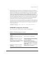
Conventions
Table 1 and Table 2 list conventions that are used throughout this guide.
Table 1: Notice Icons
Icon
Notice Type
Alerts you to...
Note
Important features or instructions.
Caution
Risk of personal injury, system damage, or loss of data.
Warning
Risk of severe personal injury.
Table 2: Text Conventions
Convention
Description
Screen displays
This typeface indicates command syntax, or represents information
as it appears on the screen.
Screen displays
bold
This typeface indicates how you would type a particular command.
The words “enter”
and “type”
When you see the word “enter” in this guide, you must type
something, and then press the Return or Enter key. Do not press the
Return or Enter key when an instruction simply says “type.”
[Key] names
Key names are written with brackets, such as [Return] or [Esc].
If you must press two or more keys simultaneously, the key names
are linked with a plus sign (+). Example:
Press [Ctrl]+[Alt]+[Del].
vi
WAN Module Installation and User Guide
Conventions
Table 2: Text Conventions (continued)
Convention
Description
Words in italicized type
Italics emphasize a point or denote new terms at the place where
they are defined in the text.
WAN Module Installation and User Guide
vii
Related Publications
The publications related to this one are:
• ExtremeWare™ release notes
• ExtremeWare Software User Guide
• Alpine 3800 Series Switch Hardware Installation Guide
• Alpine Module Installation Note
Documentation for Extreme Networks products is available on the World Wide Web at
the following location:
http://www.extremenetworks.com/
viii
WAN Module Installation and User Guide
1
Installing the WAN Module
This chapter covers the following topics:
• Installing the WAN Module on page 1-2
• Ports and Connectors on page 1-3
• Module LEDs on page 1-4
• Installing the WAN Module Software on page 1-6
Overview
The Extreme Networks WAN modules include four-port T1 or E1 modules that can be
configured to use Multilink PPP to aggregate Ethernet or IP routed traffic across
multiple T1/E1 physical links. The modules also have two general purpose 10/100
Mbps Ethernet ports. WM-4T1i is the designation of the T1 version, and WM-4E1i is the
designation of the E1 version. Also included among the WAN modules is a one-port T3
module, designated WM-1T3i, that uses PPP for its traffic.
The modules also have eight internal loopback ports. The Alpine 3800 switch modules
have hardware queues associated with the output of each port for QoS (rate shaping
and priority queueing). To implement ingress QoS, you needed to use the hardware
queues associated with a second port as a loopback port for ingress QoS.
WAN Module Installation and User Guide
1-1
Installing the WAN Module
Installing the WAN Module
All Alpine ™ 3800 series switch module cards (SMMi modules and I/O modules) are
hot-swappable. You do not need to power off the system to remove or insert a module
card.
Caution: Service to Alpine modules should be performed by trained service
personnel only. Before installing or removing any components of the system, or
before carrying out any maintenance procedures, read the safety information
provided in Appendix A of the Alpine Hardware Installation Guide.
Warning: You must install blank panels in empty slots to ensure adequate system
cooling.
To remove and replace a module card, follow these steps:
1 Prior to removing/installing a module card into the Alpine 3804 or Alpine 3808
chassis, put on the ESD wrist strap that is provided with the chassis, and connect the
metal end to the ground receptacle located on the top-right corner of the Alpine
front panel.
2 Loosen the module card by unscrewing the screws using a #2 Phillips-head
screwdriver.
3 Rotate the ejector/injector handles to disengage the module card from the backplane.
Note: Blank panels do not have ejector/injector handles, because they do not
engage the backplane. They are secured entirely by the retaining screws. In
addition, the retaining screws are not captive.
4 Slide the module card out of the chassis.
5 Slide the new module card into the appropriate slot of the chassis (SMMi modules
into the orange slot, I/O modules into Slots 1 through 4 on the Alpine 3804, or Slots
1 through 8 on the Alpine 3808), until it is fully seated in the backplane.
Caution: Ensure that the sheet metal of the module, and not the PCB board,
engages the card cage runners.
As the module begins to seat in the chassis, the ejector/injector handles will begin to
close.
6 To secure the module in the chassis, close the ejector/injector handles by pushing
them toward the center of the module card, and tighten the screws using a #2
Phillips-head screwdriver.
1-2
WAN Module Installation and User Guide
Ports and Connectors
Note: Tighten the screws before inserting additional modules. If you insert
additional modules before tightening the screws, you might unseat modules
that you have not secured.
Caution: You can only install I/O modules in the slots labeled Slot 1 through
Slot 4 on the Alpine 3804, or Slot 1 through Slot 8 on the Alpine 3808. Forceful
insertion can damage the I/O module and the connector pins on the backplane.
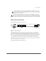
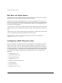
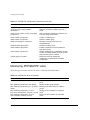
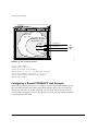
Ports and Connectors
The WM-4T1i module is shown in Figure 1-1.
Module status
LEDs
T1 ports
10/100 Mbps ports
38_WM4T1i
Figure 1-1: WM-4T1i Module
The WM-4T1i module has four T1 ports and two general purpose 10/100 Ethernet
ports. The WM-4T1i also has eight internal loopback ports. Internal loopback ports
allow you to configure bi-directional rate-limiting without tying up any of the external
ports for ingress rate shaping. Internal loopback ports are marked with the notation
“iL” when displayed on the command line or with ExtremeWare Vista Web access.
The WM-4E1i module has four E1 ports in place of the T1 ports found in the WM-4T1i
module. It is identical in all other respects.
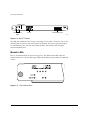
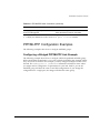
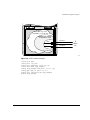
The WM-1T3i module is shown in Figure 1-2.
WAN Module Installation and User Guide
1-3
Installing the WAN Module
Module reset
Module status
LEDs
T3 port
10/100 Mbps ports
38_WM1T3i
Figure 1-2: WM-1T3i Module
The WM-1T3i module has one T3 port, consisting of a two BNC connectors, one for the
transmit path and one for the receive path. The module also has two general purpose
10/100 Ethernet ports. Like the other WAN modules, the WM-1T3i also has eight
internal loopback ports.
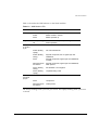
Module LEDs
The T1/E1 module LEDs are shown in Figure 1-3. The WM-1T3i module LEDs are
similar, but there is only one WAN port LED and the Ethernet port LEDs are numbered
2 and 3.
Figure 1-3: T1/E1 Module LEDs
1-4
WAN Module Installation and User Guide
Ports and Connectors
Table 1-1 describes the LED behavior on the WAN modules.
Table 1-1: WAN Module LEDs
LED
Color
Indicates
Status
Off
No power
Amber
Module seated in chassis
Green
Module powered up
Green (blinking)
Power-on Self Test (POST) is running
Off
Normal operation
Amber
Near-end fault detected (for example, no cable)
Amber (blinking
rapidly)
Far-end fault detected
Amber (blinking
slowly)
Physical link present, but no higher-layer link
established
Green
Physical link present, higher-layer link established,
no traffic
Alternating green
and amber
Physical link present, higher-layer link established,
traffic present
Green (blinking
slowly)
Port disabled or unconfigured
Green (blinking
rapidly)
Loopback testing mode
Off
No link present
Green
Link present
Alternating green
and amber
Traffic present
Diag
WAN port
(1-4)T1/E1
(1)T3
10/100 port
(5,6)T1/E1
(2,3)T3
The slowly blinking LEDs cycle once per second. The rapidly blinking LEDs cycle twice
a second.
WAN Module Installation and User Guide
1-5
Installing the WAN Module
Installing the WAN Module Software
Once the WAN module is installed in the chassis, you might need to update the image
file on the module. See the release notes for your version of ExtremeWare for details.
(You might also need to update the image on the SMMi to one that will support the
module. See the ExtremeWare Software User Guide for more information on updating the
SMMi image.)
The image file contains the executable code that runs on the module. As new versions
of the image are released, you should upgrade the software running on your module.
The image installed on the SMMi and the image installed on the module must be
compatible. New SMMi images and module images are released together, so if you
upgrade both at the same time, you will be certain to have compatible images. If this is
not feasible, see the Extreme Networks customer support website for compatibility
information.
The image is downloaded from either a Trivial File Transfer Protocol (TFTP) server on
the network or from a PC connected to the serial port using the XMODEM protocol.
Downloading a new image involves the following steps:
• Load the new image onto a TFTP server on your network (if you will be using
TFTP).
• Load a new image onto a PC (if you will be using XMODEM).
• Download the new image to the module using the command
download image slot <slot> [<ipaddress> | <hostname>] <filename>
{primary | secondary}
where the following is true:
slot — Is the slot in which the module is installed.
ipaddress — Is the IP address of the TFTP server.
hostname — Is the hostname of the TFTP server. (You must enable DNS to use this
option. See the ExtremeWare Software User Guide for more information.)
filename — Is the filename of the new image.
primary — Indicates the primary image.
secondary — Indicates the secondary image.
1-6
WAN Module Installation and User Guide
Installing the WAN Module Software
The module can store up to two images; a primary and a secondary. When you
download a new image, you must select into which image space (primary or secondary)
the new image should be placed. If not indicated, the primary image space is used.
You can select which image the switch or module will load on the next reboot by using
the following command:
use image {slot <slot>} [primary | secondary]
WAN Module Installation and User Guide
1-7
Installing the WAN Module
1-8
WAN Module Installation and User Guide
2
Configuring the WAN Physical
Link
This chapter covers the following topics:
• Configuring WAN Physical Links on page 2-2
• Monitoring WAN Physical Links on page 2-8
Overview
In this document, WAN refers to either T1, E1, or T3 technologies. T1 is a mature
technology originally developed for voice telephone transmission. It was used to
aggregate a number of voice lines into a single connection to the telephone network.
Today, T1 is also used to transmit digital data using widely available equipment and
established wiring commonly available in diverse locations.
A similar technology standard is in use in Europe, namely E1. T1 and E1 are similar, but
not identical.
Higher bandwidth characterizes T3 connections. Essentially, a T3 connection is
equivalent to a bundle of 28 T1 connections.
This chapter describes the T1, E1, and T3 features that can be configured in the WAN
module software.
WAN Module Installation and User Guide
2-1
Configuring the WAN Physical Link
Red, Blue, and Yellow Alarms
WAN links have error detection built into the link hardware. The hardware can detect
different types of errors, labeled red, blue and yellow alarms.
A red alarm occurs when the signal is lost or an out of frame error occurs. An out of
frame error can be caused when the framing type configured for the local interface does
not match the framing type of the incoming signal or when the incoming signal does
not contain a framing pattern.
A yellow alarm is also called a Remote Alarm Indication (RAI). When the remote end of
a link does not receive a signal, it will transmit a yellow alarm signal back to the local
end.
A blue alarm is also called an Alarm Indication Signal (AIS). A blue alarm indicates that
a device somewhere upstream has experienced a loss of signal.
Alarms affecting a link can be viewed by using one of the show commands, for
example, show ports t1 alarms.
Configuring WAN Physical Links
There are a number of parameters that can be configured for a WAN link. If you have
control of both sides of the link, then the default configuration is probably the best
choice. If you must connect to a line controlled by another organization, you will need
to configure the line to correspond with the settings at the other end. Some parameters
are only configurable, or only apply to some of the WAN link types. The following list
of parameters also displays which types of WAN links allow you to configure that
parameter:
• Cable length (T1, T3)
• Clock Source (T1, E1, T3)
• Facility Data Link (T1)
• Framing (T1, E1, T3)
• Inband Loopback Detection (T1)
• Linecoding (T1)
• Receiver Gain (E1)
• SNMP Alerts (T1, E1, T3)
2-2
WAN Module Installation and User Guide
Configuring WAN Physical Links
• Timeslots (E1)
• Yellow Alarms (T1)
Cable length
Longer cable lengths cause greater losses for signals, so transmitter hardware must
transmit at a higher level to transmit data successfully. However, too high a signal level
can cause crosstalk from one cable to another. The cablelength parameter allows you to
control the transmitter signal level for your conditions. Typically, your service provider
will suggest the correct level.
The parameter values available differ for T1 and T3 links. For E1, the parameter value is
not changeable, but is always set to 120 Ohms. However, for E1 links you can configure
the receiver gain to meet your conditions. See the section Receiver Gain on page 2-5.
For short haul connections (less than 1000 feet) the typical equipment uses less sensitive
receivers. The transmitter level for T1 is set by selecting a cable length in feet, from the
following values: 133, 266, 399, 533 or 655. For T3, select from the following values: 249
or 900. Choose the next higher value if the cable length provided by your service
provider does not match one of these values. For example, choose 133 for a 50 foot cable
and 533 for a 450 foot cable. The default value is 133, which corresponds to cables in the
range of 0-133 feet.
For longer distances (up to 6000 feet) T1 equipment uses more sensitive receivers, and
crosstalk is more likely to occur. Under these conditions, the transmitter level is set by
selecting a transmitter attenuation level in dB from the following values: -22.5, -15, -7.5,
or 0.
From lowest to highest transmitter level, use the following values for the config port
t1 cablelength command: -22.5 db, -15 db, -7.5 db, 0 db, 133 feet, 266 feet, 399 feet,
533 feet, and 655 feet.
To configure the cable length, use one of the following commands:
config ports <portlist> t1 cablelength [0 | -7.5 | -15 | -22.5] db
config ports <portlist> t1 cablelength [133 | 266 | 399 | 533 | 655]
feet
config ports <portlist> t3 cablelength [249 | 900] feet
WAN Module Installation and User Guide
2-3
Configuring the WAN Physical Link
Clock Source
A clock is used to synchronize data transmission on the line. Generally, one end of the
link provides the master clock, and the other end of the link recovers the clock from the
signal on the line. By default the clock source is derived from the line. If needed, an
internal clock is available. To configure the clock source, use the following command:
config ports <portlist> [t1 | e1 | t3] clocksource [internal | line]
Note: If the clock source is configured as “line”, but the clock cannot be
recovered from the signal on the line, the hardware will use the internal clock
instead.
Facility Data Link
Facility data link (FDL) for T1 links uses twelve bits in the ESF frame to signal
information about line and connection status. Since FDL is only meaningful for ESF
framing, FDL settings are ignored when a port is configured for SF framing. See
“Inband Loopback Detection” for information on configuring framing.
The two T1 standards supported for FDL are ATT, described by the ATT 54016
specification, and ANSI, described by the T1.403 standard. The default value is off. To
configure FDL, use the following command:
config ports <portlist> t1 fdl [off | att | ansi]
Framing
Framing is used to synchronize data transmission on the line. Framing allows the
hardware to determine when each packet starts and ends. The two choices for T1
framing are Super Frame (SF), also known as D4, and Extended Super Frame (ESF). The
ESF scheme is a newer standard and is enabled by default. To choose the T1 framing
scheme, use the following command:
config ports <portlist> t1 framing [esf | sf]
If you choose to use SF framing, you should disable yellow alarm detection for the T1
line. SF framing may generate false yellow alarms. See “Yellow Alarms” on page 2-6 for
more details.
The framing choices for E1 are CRC4 or no-CRC4. To choose the E1 framing scheme,
use the following command:
2-4
WAN Module Installation and User Guide
Configuring WAN Physical Links
config ports <portlist> e1 framing [crc4 | no-crc4]
The framing choices for T3 are C-bit and M13. To choose the T3 framing scheme, use
the following command:
config ports <portlist> t3 framing [c-bit | m13]
Inband Loopback Detection
When inband loopback detection is enabled, a specific sequence of data in the signal
payload from the remote end of the T1 link will cause the local end to enter network
line loopback mode and send any received signal back to the remote end. Inband
loopback detection is only possible if the FDL standard is configured as ATT. See
“Facility Data Link” on page 2-4 for more details. By default, inband loopback detection
is off. See “Loopback” on page 2-8 for more information about loopback modes. To
configure inband loopback detection, use the following command:
config ports <portlist> t1 lbdetect [off | inband]
Linecoding
Linecoding is the convention used to encode signals for transmission over the line.
For T1 connections you can choose from two linecoding standards, bipolar eight zero
suppression (B8ZS) or alternate mark inversion (AMI). The default value is B8ZS. To
configure linecoding, use the following command:
config ports <portlist> t1 linecoding [b8zs | ami]
Receiver Gain
The receiver gain for E1 links can be configured to improve performanance of the link.
Changing the receiver gain can help to receive the E1 signal or to reduce crosstalk.
Receiver gain is only configurable for E1 links. To configure receiver gain, use the
following command:
config ports <portlist> e1 receivergain [-12 | -43] db
SNMP Alerts
If the WAN module hardware detects a red, yellow, or blue alarm, the alarms are
displayed by using a show command. Additionally, the module can be configured to
WAN Module Installation and User Guide
2-5
Configuring the WAN Physical Link
send an SNMP alert to the SMMi in the switch when red, yellow, or blue alarms are
detected. If the module is configured to send SNMP alerts, and the switch is configured
to send SNMP trap messages, then the switch will send a message to any SNMP trap
receivers that have been configured. To configure SNMP trap receivers, and for more
information about configuring SNMP in ExtremeWare, see the ExtremeWare Software
User Guide.
The module can also be configured not to send an SNMP alert to the SMMi. Any red,
yellow, or blue alarms will not be reported to the SNMP trap receivers. The default
value for SNMP alerts is enabled. To configure whether SNMP alerts are generated from
WAN alarms, use the following command:
config ports <portlist> [t1 | e1 | t3] snmp alert [enable | disable]
Timeslots
The E1 signal is divided into thirty-two timeslots, numbered 0 through 31. The first
timeslot (0) is reserved and cannot be used to transmit data. The timeslot numbered 16
is often used for voice phone calls in installations that combine voice and data. For
installations that use the full E1 bandwith for data communications, you will not need
to configure which timeslots are used. For installations that do not use the total E1
bandwith, your E1 provider will tell you which timeslots to use.
To configure which timeslots to use for your E1 link, use the following command:
config ports <portlist> e1 timeslots <timeslots>
A timeslot list uses a dash to represent a range of numbers and a comma to separate
single numbers or ranges. Valid timeslots range from 1 to 31. For example, to specify
timeslots 1 through 15 and 17 through 31 for the E1 port 1 on slot 4, use the following
command:
config ports 4:1 e1 timeslots 1-15,17-31
Yellow Alarms
A yellow alarm occurs on a device when its signal is not received at the remote end. It
is also called a Remote Alarm Indication (RAI). You can disable detection and
generation of yellow alarms for a T1 port. When SF framing is used, yellow alarm
detection and generation should be set to off, because detection of yellow alarms is not
reliable when data traffic is transmitted with SF framing (data traffic often contains bit
combinations that do not occur for encoded voice traffic). The default value for yellow
2-6
WAN Module Installation and User Guide
Configuring WAN Physical Links
alarm generation and detection is both. To configure yellow alarms, use the following
command:
config ports <portlist> t1 yellow [detection | generation | both | off]
WAN Port Configuration Commands
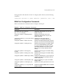
Table 2-1 describes the commands used to configure a WAN port.
Table 2-1: WAN Port Configuration Commands
Command
Description
config ports <portlist> t1 cablelength [
[133 | 266 | 399 | 533 | 655] feet
| [0 | -7.5 | -15 | -22.5] db]
Specifies the transmitter level for the
cablelength attached to the T1 port. The
default is 133 feet.
config ports <portlist> t3 cablelength [249 |
900] feet
Specifies the transmitter level for the
cablelength attached to the T3 port. The
default is 249 feet.
config ports <portlist> [t1 | e1 | t3] clock source Specifies the clock source used for
[internal | line]
transmission. The default setting is line.
config ports <portlist> t1 fdl [off | att | ansi]
Specifies the facilities data link (FDL) format for
the port. You cannot use FDL with SF framing.
config ports <portlist> t1 framing [esf | sf]
Specifies the framing type. The default setting
for T1 is esf, Extended Super Frame (ESF).
If sf, Super Frame (SF), is chosen for T1, set
yellow alarm detection to off, since a yellow
alarm can be incorrectly detected with SF
framing.
config ports <portlist> e1 framing [crc4 |
no-crc4]
Specifies the framing type. The default setting
for E1 is crc4.
config ports <portlist> t3 framing [c-bit | m13]
Specifies the framing type. The default setting
for T3 is c-bit.
config ports <portlist> t1 lbdetect [off | inband]
Enables and disables the T1 port to respond to
loopback requests from the remote end. The
default setting is off.
config ports <portlist> t1 linecode [b8zs | ami]
Sets the linecoding for T1 ports. The default
setting is b8zs.
config ports <portlist> e1 receivergain [-12 |
-43] db
Specifies the receiver gain level for an E1 link.
config ports <portlist> [t1 | e1 | t3] snmp alert
[enable | disable]
Enables and disables SNMP alerts. The default
setting is enabled.
WAN Module Installation and User Guide
2-7
Configuring the WAN Physical Link
Table 2-1: WAN Port Configuration Commands (continued)
Command
Description
config ports <portlist> e1 timeslots <timeslots>
Sets the timeslots for data used on the E1 link.
Timeslots range from 1 to 31.
config ports <portlist> t1 yellow [detection |
generation | both | off]
Enable and disable yellow alarm detection and
generation for T1 ports.
Monitoring WAN Physical Links
T1, E1, and T3 devices have a built-in facility designed for troubleshooting the physical
link, called loopback. The link can also be monitored using show commands to display
the current configuration of the link, any alarms on the link, link statistics, and link
errors.
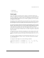
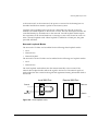
Loopback
The WAN device can be set up to loopback, that is, return a transmitted signal back to
the sender so it can be compared with the original. There are several different types of
loopback available to test different parts of the device and the line, as specified in the
T1, E1, and T3 standards.
Local WAN Port
Remote WAN Port
Data out
Data in
Data in
Data out
Framer
Framer
Data with framing
XM_010
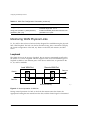
Figure 2-1: Normal operation of WAN link
During normal operation of a link, as the local data stream enters the framer, the
appropriate framing bits are inserted into the data, and the framed signal is transmitted
2-8
WAN Module Installation and User Guide
Monitoring WAN Physical Links
to the remote end. At the remote end, the process is reversed as the framing bits are
discarded and the data stream is passed to the remote system.
Loopback can be enabled on the near-end of a WAN link, but only the T1 and T3
modules can enable loopback on the far-end of a link. The near-end loopback modes are
controlled directly by the hardware on the near-end. Far-end loopback modes require
the cooperation of the far-end hardware. A message is sent to the far-end to cause it to
enter a far-end loopback mode. When loopback is enabled on a WAN port, the green
port LED will blink.
Near-end Loopback Modes
The near-end of T1 links can be enabled for the following three loopback modes:
• Local
• Network Line
• Network Payload
The near-end of E1 and T3 links can be enabled for the following two loopback modes:
• Local
• Network Line
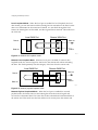
The local loopback mode reflects the data stream internally to the near-end. The
network line loopback mode reflects the signal to the far-end. The network payload
mode reflects the data carried in the signal and regenerates framing information back to
the far-end.
Local WAN Port
Remote WAN Port
Data out
Data in
Data in
Data out
Framer
Framer
XM_011
Figure 2-2: Local loopback mode
WAN Module Installation and User Guide
2-9
Configuring the WAN Physical Link
Local Loopback Mode. When the local port is enabled for local loopback, the local
data stream goes into the framer and the framing bits are inserted into the data, but the
data is not transmitted to the remote end. Instead, it is sent back through the local
framer, the framing bits are discarded, and the original data is returned. This mode tests
the local end.
Local WAN Port
Remote WAN Port
Data in
Data out
Data out
Data in
Framer
Framer
XM_012
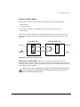
Figure 2-3: Network line loopback mode
Network Line Loopback Mode. When the local port is enabled for network line
loopback mode, the received signal is sent back to the remote end without reframing
the data. This mode primarily tests the integrity of the line from the remote side.
Local WAN Port
Remote WAN Port
Data out
Data in
Data in
Data out
Framer
Framer
XM_013
Figure 2-4: Network payload loopback mode
Network Payload Loopback Mode. When the local port is enabled for network
payload mode, the framer removes the framing bits from the received signal and
recovers the transmitted data. This same data is then reframed and transmitted back to
the remote end. This mode tests the line and the local circuitry from the remote side.
2-10
WAN Module Installation and User Guide
Monitoring WAN Physical Links
Far-End Loopback Modes
The far-end of T1 links can be enabled for the following two loopback modes:
• Remote Line
• Remote Payload
The far-end of T3 links can be enabled for the following loopback mode:
• Remote Line
The remote line mode reflects the received signal back to the near-end. The remote
payload mode reflects the data and regenerates the framing information back to the
near-end.
Local WAN Port
Remote WAN Port
Data in
Data out
Data out
Data in
Framer
Framer
XM_014
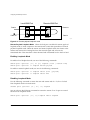
Figure 2-5: Remote line loopback mode
Remote Line Loopback Mode. When the local port is enabled for remote line
loopback mode, it sends a request to the remote end to enter the equivalent of network
line loopback mode. The signal transmitted to the remote end will be retransmitted as
received back to the local end.
Note: If the T1 line is configured to use the ATT FDL standard, the remote end
must be configured to detect inband loopback requests for the remote end to
enter remote line loopback mode.
WAN Module Installation and User Guide
2-11
Configuring the WAN Physical Link
Local WAN Port
Remote WAN Port
Data in
Data out
Data out
Data in
Framer
Framer
XM_015
Figure 2-6: Remote payload loopback mode
Remote Payload Loopback Mode. When the local port is enabled for remote payload
loopback mode, it sends a request to the remote end to enter the equivalent of network
payload loopback mode. When the remote end enters loopback mode, the framer at the
remote end removes the framing bits from the received signal and recovers the
transmitted data. This same data is then reframed and transmitted back to the local end.
Enabling Loopback Mode
To enable a local loopback mode, use one of the following commands:
enable ports <portlist> [t1 | e1 |t3] loopback [local | network line]
enable ports <portlist> t1 loopback network payload
To enable a remote loopback mode, use one of the following commands:
enable ports <portlist> t1 loopback remote [line | payload]
enable ports <portlist> t3 loopback remote line
Disabling Loopback Mode
Use the following command to return the near and remote side of a T1, E1 or T3 link
from loopback mode to normal mode:
disable ports <portlist> [t1 | e1 | t3] loopback
You can also use the following command to return the remote T1 or T3 port to normal
function from loopback mode:
enable ports <portlist> [t1 | t3] loopback remote loopdown
2-12
WAN Module Installation and User Guide
Monitoring WAN Physical Links
WAN Port Monitoring Commands
Table 2-2 describes the commands used to monitor a WAN port.
Table 2-2: WAN Port Monitoring Commands
Command
Description
disable ports <portlist> [t1 | e1 | t3] loopback
Disables the current loopback mode and return
to normal function.
enable ports <portlist> [t1 | e1 | t3] loopback
[local | network line]
enable ports <portlist> t1 loopback network
payload
Enables the near-end port loopback modes.
enable ports <portlist> [t1 | t3} loopback remote Enables the far-end T1 or T3 port loopback
[line | payload | loopdown]
modes and stops the loopback
show ports {<portlist>} {t1 | e1 | t3} stats
Displays real-time port statistics.
show ports {<portlist>} [t1 | e1 | t3] alarms
Displays real-time port alarms.
show ports {<portlist>} [t1 | e1 | t3]
configuration
Displays the port configuration and status.
show ports {<portlist>} [t1 | t3] errors [near-end
| far-end] [totals | intervals | current]
show ports {<portlist>} e1 errors near-end
[totals | intervals | current]
Displays current and past errors.
show ports {<portlist>} [t1 | e1 | t3] info
Displays the port configuration and status.
WAN Module Installation and User Guide
2-13
Configuring the WAN Physical Link
2-14
WAN Module Installation and User Guide
3
Configuring PPP and MLPPP
This chapter covers the following topics:
• Multilink PPP and Multilink Groups on page 3-2
• Configuring a PPP/MLPPP Link on page 3-3
• Monitoring PPP/MLPPP Links on page 3-6
• PPP/MLPPP Configuration Examples on page 3-7
Overview
Point-to-Point Protocol (PPP) is used across the entire range of communication speeds
and devices found on the internet. Typically, PPP uses Layer 3 to connect two broadcast
networks, say two ethernet LANs, into a single WAN by transporting IP packets over a
link. PPP can also use Layer 2 to bridge VLAN traffic.
Multilink PPP (MLPPP) is a protocol for combining a number of PPP links into one
bundle that transports traffic over the links in the bundle. Multilink PPP is supported
for T1 and E1 technologies in ExtremeWare, but not for T3. Instead, a T3 link is
configured as a single PPP link.
A multilink group is a bundle of individual PPP links that are configured to work
together as a single link. With a multilink group configured, it is easy to add or remove
PPP links in order to provide appropriate bandwidth. The multilink group balances
traffic among the individual PPP links and properly sequences packets across the
multilink group.
WAN Module Installation and User Guide
3-1
Configuring PPP and MLPPP
Typically, you would create a multilink group, configure the multilink group by adding
T1 or E1 ports and configuring PPP/MLPPP parameters, add the multilink group to a
VLAN, and finally, enable the multilink group.
For a T3 port, you would configure its PPP parameters and add it to a VLAN.
Multilink PPP and Multilink Groups
Each multilink PPP group is given a name, up to 16 characters in length. All named
components of the switch configuration must have unique names, so multilink groups
and VLANs cannot have identical names. See the ExtremeWare Software User Guide for
more information on allowable names for named components. Components are named
using the create command. Once a component is named, you do not need to use the
keyword for the component (see the shortcut below).
Create the multilink group using the following command:
create multilink <groupname>
Once the multilink group is created, assign ports to it. All T1/E1 ports must be added
as tagged ports. If the ports are configured as IPCP ports, then the tags will be stripped
as traffic passes over the link. BCP-configured ports will pass the tag across the link. See
the section “Encapsulation” for more information. Add ports by using the following
command:
config multilink <groupname> add ports <portlist> tag
or you can use the following shortcut:
config <groupname> add ports <portlist> tag
If the first port added to a multilink group is already configured for PPP, the multilink
group will inherit the configuration of the first port. Any other ports added to the link
will be configured to match the multilink configuration. The next section lists the
configuration commands for multilink groups and single PPP links.
Once the multilink group has been configured, it is added to a VLAN so that it can pass
traffic from the VLAN across the link. To add a multilink group to a VLAN, use the
following command:
config vlan <vlan> add multilink <groupname>
3-2
WAN Module Installation and User Guide
Configuring a PPP/MLPPP Link
Typically the last step in configuring a multilink group is to use the following command
to enable it:
enable multilink <groupname>
Any changes to an enabled multilink group will not take effect until the multilink group
is restarted. To restart a multilink group, use the following command:
restart multilink <groupname>
Configuring a PPP/MLPPP Link
All of the PPP configuration commands can be used to configure a single port or to
configure a multilink group, so the following sections for PPP links also apply to
MLPPP links. To configure a PPP/MLPPP link you will need to choose the
authentication and encapsulation for the link.
If you change the configuration of an enabled PPP or MLPPP link, the changes will not
take effect until the link is restarted. To restart a PPP link, use the following command:
restart ports <portlist>
To restart an MLPPP link, use the following command:
restart multilink <groupname>
Authentication
By default, no authentication is configured on PPP links since the WM-4T1i module will
typically be used with leased lines—where both sides of the link are controlled and
authentification is not required. If authentication is needed, the WM-4T1i module
supports either PAP or CHAP. Password authentication protocol (PAP) authenticates a
user as the connection is established by sending a username and password. Challenge
Handshake Authentication Protocol (CHAP) authenticates a user by sending a challenge
across the link. The remote end calculates a response based on the user password and
sends the response back across the link. CHAP is a more secure authentication protocol
than PAP. The link can also be configured to attempt to use CHAP first, followed by
PAP, if CHAP fails.
To configure authentication on a PPP link, use the following command:
WAN Module Installation and User Guide
3-3
Configuring PPP and MLPPP
config ppp authentication [off | chap | pap | chap-pap] [ports
<portlist> | multilink <groupname>]
PPP Link Username
When the local end of a link initiates a PPP connection, the local end must send the
appropriate authentication information. For PAP it sends the username and password,
for CHAP it sends the username and must respond correctly to the challenge, and for
no authentication it sends nothing. To configure the username and password used to
initiate the link, use the following command:
config ppp user <username> {encrypted} <password> [ports <portlist> |
multilink <groupname>]
The encrypted keyword is used to hide the password when the switch configuration is
displayed; it does not control whether the password is encrypted across the link during
authentication.
PPP User Accounts
When the remote end initiates the link, the local end must verify the authentication
information. The local end maintains a list of authorized user accounts and passwords.
To add a user to the list, use the following command:
create account pppuser <name> {encrypted} {<password>}
Encapsulation
The packets passed over the PPP/MLPPP link can use either bridged or routed
encapsulation. You would use bridged packets if you plan to have VLANs span the
link. You would use routed packets if the link connects two different routed networks
or separate VLANs.
Using bridged packets allows the VLAN tags to be carried across the PPP/MLPPP link.
Bridged packets are transported using the PPP Bridging Control Protocol (BCP),
described in RFC 2878. When the encapsulation is set to BCP, 802.1Q and 802.1p
information is preserved and transported across the link. On a WAN module, a VLAN
may only contain one BCP encapsulated link, but you may have multiple VLANs span
the link.
3-4
WAN Module Installation and User Guide
Configuring a PPP/MLPPP Link
Routed packets are transported across a PPP/MLPPP link using IP Control Protocol
(IPCP), described in RFC 1332. This is the encapsulation that is familiar to most users of
PPP. The routed packets do not contain Ethernet headers so cannot preserve VLAN
tags. However, the WAN ports still must be added as tagged ports to the VLAN that
contains them. The module uses the tags internally and strips them off before the
packets are transmitted. The IP addresses used for the PPP/MLPPP link are taken from
the IP address assigned to the VLAN at each end of the link. The VLAN that contains
the IPCP encapsulated PPP/MLPPP ports cannot contain other ports. In other words,
the only ports allowed in the VLAN are those that make up the IPCP encapsulated
link.There can only be one VLAN spanning an IPCP-encapsulated link.
You must have one and only one encapsulation type configured on a PPP/MLPPP link.
Setting BCP encapsulation off implies that IPCP encapsulation is on. The default setting
is BCP encapsulation on and IPCP encapsulation off. To configure encapsulation, use
the following command:
config ppp [bcp [on | off] | ipcp [on | off]] [ports <portlist> |
multilink <groupname>]
PPP/MLPPP Configuration Commands
Table 3-1 describes the commands used to configure a PPP/MLPPP link.
Table 3-1: PPP/MLPPP Configuration Commands
Command
Description
config multilink <groupname> add ports
<portlist>
Adds ports to a multilink group.
config multilink <groupname> delete ports
<portlist>
Removes ports from a multilink group.
config ppp authentication [off | chap | pap |
chap-pap]
[ports <portlist> | multilink <groupname>]
Sets the authentication method for a PPP link
or a MLPPP multilink group. The default setting
is to use no authentication.
config ppp [bcp [on | off] | [ipcp [on | off]] [ports Sets the encapsulation method for a
<portlist> | multilink <groupname>]
PPP/MLPPP link. You cannot set both to on, or
both to off. Configuring bcp on implies ipcp off;
configuring ipcp on implies bcp off. The default
setting is bcp on.
config ppp user <username> {encrypted}
<password>
[ports <portlist> | multilink <groupname>]
WAN Module Installation and User Guide
Sets the username sent to the remote end of a
PPP/MLPPP link for authentication.
3-5
Configuring PPP and MLPPP
Table 3-1: PPP/MLPPP Configuration Commands (continued)
Command
Description
config vlan <vlan> add multilink <groupname>
Adds an MLPPP multilink group to a VLAN.
config vlan <vlan> delete multilink
<groupname>
Removes an MLPPP multilink group from a
VLAN.
create account pppuser <name> {encrypted}
{<password>}
Adds a username that will be accepted by the
local end during authentication.
create multilink <groupname>
Creates a multilink group.
delete multilink <groupname>
Deletes a multilink group.
delete account pppuser <username>
Removes a username from the local
authentication list.
disable multilink <groupname>
Disables a multilink group.
enable multilink <groupname>
Enables a multilink group (and enables all
ports in the group).
restart multilink <groupname>
Restarts multilink group. Configuration changes
made to an enable multilink group will not take
effect until the group is restarted.
unconfig ppp port <portlist>
Resets the port to the default PPP
configuration, no authentication and BCP
encapsulation.
Monitoring PPP/MLPPP Links
The following commands monitor the status of the PPP and MLPPP links.
Table 3-2: PPP/MLPPP Show Commands
Command
Description
show multilink <groupname>
Displays the configuration of the multilink
group.
show multilink [<groupname>] stats {detail}
Displays multlink group statistics.
show multilink [<groupname>] [t1 | e1] alarms
{detail}
Displays T1/E1 alarm status for multilink
groups.1
show multilink [<groupname>] t1 errors
[near-end | far-end] [totals | intervals | current]
Displays T1 error statistics for a multilink
group.2
show multilink [<groupname>] e1 errors
near-end [totals | intervals | current]
Displays E1 error statistics for a multilink
group.
3-6
WAN Module Installation and User Guide
PPP/MLPPP Configuration Examples
Table 3-2: PPP/MLPPP Show Commands (continued)
Command
Description
show ppp {<portlist>} {detail}
Shows PPP configurations.
show accounts pppuser
Show the PPP accounts on the switch.
1. To display alarm status for T3 links, use the show ports t3 alarms command
2. To display error statistics for T3 links, use the show ports t3 errors command
PPP/MLPPP Configuration Examples
The following examples show how to configure multilink groups.
Configuring a Bridged PPP/MLPPP Link Example
The following example shows how to configure a BCP-encapsulated multilink group.
BCP is the default encapsulation, so it is not explicitly included in this example. While
only one VLAN is shown in this example, you may configure multiple VLANs across
the link. The config ports t1 clocksource command is included to show where
you might need to configure the T1 parameters for your link. Each T1 port in the
multilink group will have the same T1 and PPP configurations. If you change the
configuration for a single port, the change will affect the entire group.
WAN Module Installation and User Guide
3-7
Configuring PPP and MLPPP
VLAN alpha
tag = 1001
Multilink bcp_example
encapsulation = BCP
PPP
PPP
PPP
T1 port 4:1
To
switch
#2
T1 port 4:2
T1 port 4:3
Switch #1
Figure 3-1: BCP multilink example
create
config
create
config
config
config
enable
XM_007
vlan alpha
alpha tag 1001
multilink bcp_example
ports 4:1-4:3 t1 clocksource internal
bcp_example add ports 4:1-4:3 tag
alpha add multilink bcp_example
bcp_example
Configuring a Routed PPP/MLPPP Link Example
The following example shows how to configure a IPCP-encapsulated multilink group.
The VLAN that contains the IPCP-encapsulated multilink group cannot contain any
other ports, and only one VLAN is allowed across the link. Notice that the T1 ports
must be added as tagged ports even though the tag will be removed before the packet
is transmitted over this link.
3-8
WAN Module Installation and User Guide
PPP/MLPPP Configuration Examples
VLAN beta tag = 1001
IP address = 10.10.10.1/24
Multilink ipcp_example
encapsulation = IPCP
PPP
PPP
PPP
Switch #1
T1 port 4:1
T1 port 4:2
T1 port 4:3
To
switch
#2
XM_008
Figure 3-2: IPCP multilink example
create
config
config
create
config
config
config
enable
vlan beta
beta tag 1001
beta ipaddress 10.10.10.1/24
multilink ipcp_example
ipcp_example add ports 4:1-4:3 tag
ppp ipcp on ports 4:1-4:3
beta add multilink ipcp_example
ipcp_example
WAN Module Installation and User Guide
3-9
Configuring PPP and MLPPP
3-10
WAN Module Installation and User Guide
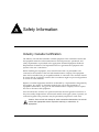
A
Safety Information
Industry Canada Certification
The Industry Canada label identifies certified equipment. This certification means that
the equipment meets the telecommunications network protective, operational, and
safety requirements as prescribed in the appropriate Terminal Equipment Technical
Requirements documents. The Department does not guarantee the equipment will
operate to the user’s satisfaction.
Before installing this equipment, users should ensure that it is permissible to be
connected to the facilities of the local telecommunications company. The equipment
must also be installed using an acceptable method of connection. The customer should
be aware that the compliance with the above conditions might not prevent degradation
of service in some situations.
Repairs to certified equipment should be coordinated by a representative designated by
the supplier. Any repairs or alterations made by the user to this equipment, or
equipment malfunctions, may give the telecommunications company cause to request
the user to disconnect the equipment.
Users should ensure for their own protection that the electrical ground connections of
the power utility telephone lines and internal metallic water pipe system, if present, are
connected together. This precaution may be particularly important in rural areas.
Caution: Users should not attempt to make connections themselves, but should
contact the appropriate electric inspection authority, or electrician, as
appropriate.
WAN Module Installation and User Guide
A-1
FCC Certification
This equipment complies with Part 68 of the FFC rules. On the printed circuit board of
this equipment is a label that contains, among other information, the FCC registration
number for this equipment. If requested, provide this information to your telephone
company.
If your WM-4T1i module causes harm to the telephone network, the Telephone
Company may discontinue your service temporarily. If possible, they will notify you in
advance. But if advance notice isn’t practical, you will be notified as soon as possible.
You will be advised of your right to file a complaint with the FCC.
Your telephone company may make changes in its facilities, equipment, operations, or
procedures that could affect the proper operation of your equipment. If they do, you
will be given advance notice so as to give you an opportunity to maintain
uninterrupted service.
If you experience trouble with this WM-4T1i module, please contact Extreme Networks
at 3585 Monroe Street, Santa Clara, CA, 95051, for repair/warranty information. The
telephone company may ask you to disconnect this equipment from the network until
the problem has been corrected or you are sure that the equipment is not
malfunctioning.
There are no repairs that can be made by the customer to the WM-4T1i.
A-2
WAN Module Installation and User Guide
Index
text, Preface
CRC4 E1 line framing
Numerics
802.1p
802.1Q
3-4
3-4
A
alarms
alternate mark inversion (AMI)
AMI linecoding
authentication
2-2
2-5
2-5
3-3
B
B8ZS linecoding
BCP encapsulation
bipolar eight zero suppression (B8ZS)
blue alarms
bridged PPP links
2-5
3-4
2-5
2-2
3-4
C
cable length
2-3
C-bit T3 line framing
2-5
Challenge Handshake Authentication Protocol
(CHAP)
3-3
CHAP
3-3
clock source
2-4
configuring
E1 port
2-2
encapsulation
3-5
T1 port
2-2
conventions
notice icons, Preface
-vi
-vi
2-4
E
E1 port
clock source
configuration commands (table)
configuring
framing
monitoring commands (table)
encapsulation
BCP
configuring
IPCP
ESF (Extended Super Frame) T1 line framing
2-4
2-7
2-2
2-4
2-13
3-4
3-5
3-5
2-4
F
facility data link
framing
C-bit
CRC4
ESF (Extended Super Frame)
M13
SF (Super Frame)
2-4
2-4
2-5
2-4
2-4
2-5
2-4
I
IPCP encapsulation
3-5
L
LEDs
i
T1 port
linecoding
AMI
B8ZS
loopback detection
1-5
2-5
2-5
2-5
2-5
user accounts, PPP
username, PPP
3-4
3-4
V
M
M13 T3 line framing
MLPPP
multilink group
adding to VLAN
Multilink PPP (MLPPP)
U
2-5
3-1
3-2
3-2
3-1
VLAN tags
3-4
W
WAN port
configuration commands (table)
monitoring commands (table)
2-7
2-13
P
PAP
Password authentication protocol (PAP)
Point-to-Point Protocol (PPP)
PPP
PPP links
bridged
routed
PPP user accounts
PPP username
PPP/MLPPP
configuration commands (table)
3-3
3-3
3-1
3-1
3-4
3-4
3-4
3-4
3-5, 3-6
R
red alarms
RFC 1332
RFC 2878
routed PPP links
2-2
3-5
3-4
3-4
S
SF (Super Frame) T1 line framing
2-4
T
T1 port
cable length
clock source
configuration commands (table)
configuring
facility data link
framing
LEDs
linecoding
loopback detection
monitoring commands (table)
T3 port
configuration commands (table)
monitoring commands (table)
ii - INDEX
2-3
2-4
2-7
2-2
2-4
2-4
1-5
2-5
2-5
2-13
2-7
2-13
Y
yellow alarms
2-2
Index of Commands
C
config multilink add ports
config multilink delete ports
config ports e1 clock source
config ports e1 framing
config ports e1 receivergain
config ports e1 snmp alert
config ports e1 timeslots
config ports t1 cablelength
config ports t1 clock source
config ports t1 fdl
config ports t1 framing
config ports t1 lbdetect
config ports t1 linecode
config ports t1 snmp alert
config ports t1 yellow
config ports t3 cablelength
config ports t3 clock source
config ports t3 framing
config ports t3 snmp alert
config ppp authentication
config ppp bcp
config ppp ipcp
config ppp user
config vlan add multilink
config vlan delete multilink
create account pppuser
create multilink
D
3-5
3-5
2-7
2-7
2-7
2-7
2-8
2-7
2-7
2-7
2-7
2-7
2-7
2-7
2-8
2-7
2-7
2-7
2-7
3-5
3-5
3-5
3-5
3-6
3-6
3-6
3-6
delete account pppuser
delete multilink
disable multilink
disable ports e1 loopback
disable ports t1 loopback
disable ports t3 loopback
3-6
3-6
3-6
2-13
2-13
2-13
E
enable multilink
enable ports e1 loopback
enable ports t1 loopback
enable ports t1 loopback remote
enable ports t3 loopback
enable ports t3 loopback remote
3-6
2-13
2-13
2-13
2-13
2-13
R
restart multilink
3-6
S
show accounts pppuser
show multilink
show multilink e1 alarms
show multilink e1 errors
show multilink stats
show multilink t1 alarms
show multilink t1 errors
show ports e1 alarms
show ports e1 configuration
show ports e1 errors
3-7
3-6
3-6
3-6
3-6
3-6
3-6
2-13
2-13
2-13
Index of Commands - i
show ports e1 info
show ports e1 stats
show ports stats
show ports t1 alarms
show ports t1 configuration
show ports t1 errors
show ports t1 info
show ports t1 stats
show ports t3 errors
show ports t3 info
show ports t3 stats
show ppp
2-13
2-13
2-13
2-13
2-13
2-13
2-13
2-13
2-13
2-13
2-13
3-7
U
unconfig ppp
ii - Index of Commands
3-6