1
Disclaimer
Welch Allyn reserves the right to make changes in specifications and
other information contained in this document without prior notice, and the
reader should in all cases consult Welch Allyn to determine whether any
such changes have been made. The information in this publication does
not represent a commitment on the part of Welch Allyn.
Welch Allyn shall not be liable for technical or editorial errors or
omissions contained herein; nor for incidental or consequential
damages resulting from the furnishing, performance, or use of this
material.
This document contains proprietary information which is protected by
copyright. All rights are reserved. No part of this document may be
photocopied, reproduced, or translated into another language without the
prior written consent of Welch Allyn, Incorporated.
1998 Welch Allyn, Inc. All rights reserved.
Data Collection Division Web Address: http://dcd.welchallyn.com
The CE mark on the product indicates that the system has been tested to and
conforms with the provisions noted within the 89/336/EEC Electromagnetic
Compatibility Directive and the 73/23/EEC Low Voltage Directive.
For further information, please contact:
Welch Allyn Ltd.
Block 1, Bracken Business Park
Sandyford
Co Dublin
Ireland
or
Welch Allyn Ltd.
1st Floor
Dallam Court Dallam Lane
Warrington, Cheshire WA2 7LT
England
Welch Allyn shall not be liable for use of our product with equipment
(i.e., power supplies, personal computers, etc.) that is not CE marked and
does not comply with the Low Voltage Directive.
C.S.A. Statement
This product must be used with a certified Class 2 power
supply or be powered by a certified SELV (Safety Extra Low
Voltage) output.
RF Approvals
This product complies with the following:
U.S.A.
FCC Part 15.249 Certified
Canada
RSS 210 Certified
Europe
ETS 300 328 Certified
Mexico
NOM–EM–121–SCT1–1994 Certified
Safety Approvals This product complies with the following:
U.S.A.
UL Listed, C22.2 No. 950 / UL 1950
Canada
cUL Listed
Europe TÜV Rheinland GS Licensed, EN 60950 (IEC 950)
Mexico
NYCE Certified, NOM 19
This device complies with part 15 of the FCC Rules. Operation is subject to the
following two conditions: (1) this device may not cause harmful interference, and
(2) this device must accept any interference received, including interference that
may cause undesired operation.
FCC Class B Compliance Statement
This equipment has been tested and found to comply with the limits for a Class B
digital device pursuant to part 15 of the FCC Rules. These limits are designed to
provide reasonable protection against harmful interference in a residential
installation. This equipment generates, uses, and can radiate radio frequency
energy and, if not installed and used in accordance with the instructions, may
cause harmful interference to radio communications. However, there is no
guarantee that interference will not occur in a particular installation. If this
equipment does cause harmful interference to radio or television reception,
which can be determined by turning the equipment off and on, the user is
encouraged to try to correct the interference by one or more of the following
measures:
• Reorient or relocate the receiving antenna.
• Increase the separation between the equipment and receiver.
• Connect the equipment into an outlet on a circuit different from that
to which the receiver is connected.
• Consult the dealer or an experienced radio or television technician for help.
Caution: Any changes or modifications made to this device that are not
expressly approved by Welch Allyn, Inc. may void the user’s authority to
operate the equipment.
Note: To maintain compliance with FCC Rules and Regulations, cables
connected to this device must be shielded cables, in which the cable shield
wire(s) have been grounded (tied) to the connector shell.
Canadian Notice
This equipment does not exceed the Class B limits for radio noise emissions as
described in the Radio Interference Regulations of the Canadian Department of
Communications.
Le present appareil numerique n’emet pas de bruits radioelectriques depassant
les limites applicables aux appareils numeriques de la classe B prescrites dans
le Reglement sur le brouillage radioelectrique edicte par le ministere des
Communications du Canada.
CDRH Laser Safety Statement
This product complies with US DHHS 21 CFR J Part 1040.10. This product is a
CLASS II LASER PRODUCT with a maximum output of 1.0 mW at 670
nanometers and continuous wave.
EN 60825–1 Laser Safety Statement
This product is classified as a CLASS 2 LASER PRODUCT with a maximum
output of 9.0 mW at 670 nanometers per EN 60825–1:1994, Issue 2, June 1997.
Cordless Systems Manual
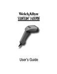
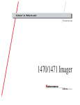
Enlarged Views of Regulatory Labels
Laser Scanner
Only:
Cordless Scanner
Left Side View
with
Battery Pack
Cordless Scanner
Right Side View
(without battery pack)
THIS DEVICE COMPLIES WITH PART
15 OF THE FCC RULES. OPERATION
IS SUBJECT TO THE FOLLOWING
TWO CONDITIONS: (1) THIS DEVICE
MAY NOT CAUSE HARMFUL INTERFERENCE, AND (2) THIS DEVICE
MUST ACCEPT ANY INTERFERENCE
RECEIVED, INCLUDING INTERFERENCE THAT MAY CAUSE
UNDESIRED OPERATION.
COMPLIES WITH 21 CFR 1040.
Cordless Systems Manual
TABLE OF CONTENTS
Section 1
Introduction & Installation
Section
Page
Introduction . . . . . . . . . . . . . . . . . . . . . . . . . . . . . . . . . . . . . . . . 1–1
Getting Started
Cordless System: Main Components . . . . . . . . . . . . . . . . . .
About the Battery Pack . . . . . . . . . . . . . . . . . . . . . . . . . . . . . .
Charging Your Battery Pack . . . . . . . . . . . . . . . . . . . . . . . . . .
Setting Up and Connecting the Cordless System . . . . . . . .
Connecting More Scanners to the System . . . . . . . . . . . . . .
Beeper and LED Sequences and Meaning . . . . . . . . . . . . .
Basic Operation of the Cordless System . . . . . . . . . . . . . . .
Communication Between Cordless System and Host . . . .
Accessories for the Cordless System . . . . . . . . . . . . . . . . . .
Section 2
1–2
1–3
1–4
1–5
1–7
1–8
1–9
1–11
1–12
Quick Start & Interface Menu
Section
Page
Introduction . . . . . . . . . . . . . . . . . . . . . . . . . . . . . . . . . . . . . . . . 2–1
Plug and Play Selections
Industrial Interface: IBM PC . . . . . . . . . . . . . . . . . . . . . . . . . . 2–2
Industrial Interface, Aux Port: RS232 . . . . . . . . . . . . . . . . . . 2–2
Industrial Interface, Aux Port: Wand Emulation . . . . . . . . . . 2–3
Terminal Interface Selections
Supported Terminals . . . . . . . . . . . . . . . . . . . . . . . . . . . . . . . . 2–4
Country Code Selections
Keyboard Country Selection . . . . . . . . . . . . . . . . . . . . . . . . . . 2–6
Keyboard Selections
Keyboard Layout Selection . . . . . . . . . . . . . . . . . . . . . . . . . . . 2–7
Keyboard Style Selections . . . . . . . . . . . . . . . . . . . . . . . . . . . 2–8
Keyboard Style Modifiers . . . . . . . . . . . . . . . . . . . . . . . . . . . . 2–9
Delays Selections
Output Delays Selection . . . . . . . . . . . . . . . . . . . . . . . . . . . . . 2–10
Wand Emulation Selections
Transmission Rate Selection . . . . . . . . . . . . . . . . . . . . . . . . . 2–11
Output Polarity Selection . . . . . . . . . . . . . . . . . . . . . . . . . . . . . 2–11
Reset Selections
Reset Factory Settings . . . . . . . . . . . . . . . . . . . . . . . . . . . . . . 2–12
Cordless Systems Manual
i
Section 3
Communications Menu
Section
Page
Introduction . . . . . . . . . . . . . . . . . . . . . . . . . . . . . . . . . . . . . . . . 3–1
Host Port Communications
Baud Rate Selection . . . . . . . . . . . . . . . . . . . . . . . . . . . . . . . .
Parity Selection . . . . . . . . . . . . . . . . . . . . . . . . . . . . . . . . . . . . .
Word Length Data Bits Selection . . . . . . . . . . . . . . . . . . . . . .
Word Length Stop Bits Selection . . . . . . . . . . . . . . . . . . . . . .
Serial Wedge Output Selection . . . . . . . . . . . . . . . . . . . . . . .
Hardware Flow Control Selection . . . . . . . . . . . . . . . . . . . . .
Host ACK Selection . . . . . . . . . . . . . . . . . . . . . . . . . . . . . . . . .
Escape Commands . . . . . . . . . . . . . . . . . . . . . . . . . . . . . . . . .
3–2
3–3
3–3
3–4
3–4
3–5
3–6
3–6
Auxiliary Port Communications
Baud Rate Selection . . . . . . . . . . . . . . . . . . . . . . . . . . . . . . . .
Parity Selection . . . . . . . . . . . . . . . . . . . . . . . . . . . . . . . . . . . . .
Word Length Data Bits Selection . . . . . . . . . . . . . . . . . . . . . .
Word Length Stop Bits Selection . . . . . . . . . . . . . . . . . . . . . .
Protocol Selection . . . . . . . . . . . . . . . . . . . . . . . . . . . . . . . . . . .
Aux Port I.D. Transmit Selection . . . . . . . . . . . . . . . . . . . . . .
Hardware Flow Control Selection . . . . . . . . . . . . . . . . . . . . .
Data Character Selection . . . . . . . . . . . . . . . . . . . . . . . . . . . .
3–7
3–8
3–8
3–9
3–9
3–9
3–10
3–10
Aux Prefix / Suffix Selections
Aux Prefix Selection . . . . . . . . . . . . . . . . . . . . . . . . . . . . . . . . . 3–12
Aux Suffix Selection . . . . . . . . . . . . . . . . . . . . . . . . . . . . . . . . . 3–12
Aux Data Formatter Selections
Aux Data Formatter . . . . . . . . . . . . . . . . . . . . . . . . . . . . . . . . . 3–15
Aux Require Data Format? . . . . . . . . . . . . . . . . . . . . . . . . . . . 3–15
Aux Data Format Editor . . . . . . . . . . . . . . . . . . . . . . . . . . . . . . 3–15
ii
Cordless Systems Manual
Section 4
Application Work Groups Menu
Section
Page
Introduction . . . . . . . . . . . . . . . . . . . . . . . . . . . . . . . . . . . . . . . . 4–1
Output Selections (User Feedback)
Application Work Group Selection . . . . . . . . . . . . . . . . . . . . .
Remove Scanner Selection . . . . . . . . . . . . . . . . . . . . . . . . . .
Beeper Volume Selection . . . . . . . . . . . . . . . . . . . . . . . . . . . .
Scanner Voting Selection . . . . . . . . . . . . . . . . . . . . . . . . . . . .
Laser Marker Beam . . . . . . . . . . . . . . . . . . . . . . . . . . . . . . . . .
AIM I.D. Transmit Selection . . . . . . . . . . . . . . . . . . . . . . . . . .
Welch Allyn Code I.D. Transmit Selection . . . . . . . . . . . . . .
4–2
4–3
4–3
4–3
4–4
4–4
4–4
Prefix / Suffix Selections
Prefix Selection . . . . . . . . . . . . . . . . . . . . . . . . . . . . . . . . . . . . . 4–6
Suffix Selection . . . . . . . . . . . . . . . . . . . . . . . . . . . . . . . . . . . . . 4–6
Data Formatter Selections
Data Formatter . . . . . . . . . . . . . . . . . . . . . . . . . . . . . . . . . . . . . 4–10
Require Data Format? . . . . . . . . . . . . . . . . . . . . . . . . . . . . . . . 4–10
Data Format Editor . . . . . . . . . . . . . . . . . . . . . . . . . . . . . . . . . . 4–10
Section 5
Symbology Menu
Section
Page
Introduction . . . . . . . . . . . . . . . . . . . . . . . . . . . . . . . . . . . . . . . . 5–1
Industrial Symbology Selections
Codabar Selection . . . . . . . . . . . . . . . . . . . . . . . . . . . . . . . . . .
Code 39 Selection . . . . . . . . . . . . . . . . . . . . . . . . . . . . . . . . . .
Code 93 Selection . . . . . . . . . . . . . . . . . . . . . . . . . . . . . . . . . .
Interleaved 2 of 5 Selection . . . . . . . . . . . . . . . . . . . . . . . . . .
Code 2 of 5 Selection . . . . . . . . . . . . . . . . . . . . . . . . . . . . . . . .
Matrix 2 of 5 Selection . . . . . . . . . . . . . . . . . . . . . . . . . . . . . . .
Code 11 Selection . . . . . . . . . . . . . . . . . . . . . . . . . . . . . . . . . .
Code 128 Selection . . . . . . . . . . . . . . . . . . . . . . . . . . . . . . . . .
5–2
5–4
5–6
5–7
5–8
5–8
5–9
5–9
Retail Symbology Selections
EAN / JAN 8 / 13 Selection . . . . . . . . . . . . . . . . . . . . . . . . . . .
UPC A Selection . . . . . . . . . . . . . . . . . . . . . . . . . . . . . . . . . . . .
UPC E0 Selection . . . . . . . . . . . . . . . . . . . . . . . . . . . . . . . . . . .
UPC E1 Selection . . . . . . . . . . . . . . . . . . . . . . . . . . . . . . . . . . .
EAN Addenda Selection . . . . . . . . . . . . . . . . . . . . . . . . . . . . .
UPC Addenda Selection . . . . . . . . . . . . . . . . . . . . . . . . . . . . .
Cordless Systems Manual
5–10
5–11
5–12
5–12
5–13
5–13
iii
Section 6
Supported Interface Keys
Section
Page
Keyboard Function Relationships . . . . . . . . . . . . . . . . . . . . . 6–1
Supported Interface Keys . . . . . . . . . . . . . . . . . . . . . . . . . . . . 6–2
Section 7
Product Specifications and Pinouts
Section
Page
Specifications
SCANTEAM 2070 Cordless Base Specifications . . . . . . . .
Radio Specifications . . . . . . . . . . . . . . . . . . . . . . . . . . . . . . . . .
SCANTEAM 3470 Cordless CCD Scanner Specifications
SCANTEAM 5770 Cordless Laser Scanner Specifications
Battery Specifications . . . . . . . . . . . . . . . . . . . . . . . . . . . . . . .
Regulatory and Safety Agency Approvals . . . . . . . . . . . . . .
Patents . . . . . . . . . . . . . . . . . . . . . . . . . . . . . . . . . . . . . . . . . . . .
7–1
7–1
7–2
7–3
7–4
7–5
7–5
Connectors & Pinouts
Auxiliary RS-232 / Wand Emulation Connector . . . . . . . . . . 7–6
Keyboard / Terminal and RS-232 (Host Port) Connector . . 7–7
External Power Connector . . . . . . . . . . . . . . . . . . . . . . . . . . . 7–7
Dimensions
Cordless Base Dimensions . . . . . . . . . . . . . . . . . . . . . . . . . . . 7–8
Cordless Scanner Dimensions . . . . . . . . . . . . . . . . . . . . . . . . 7–9
Scan Maps
Typical Performance at 20°C for SCANTEAM 3470LR . . . 7–10
Typical Performance at 20°C for SCANTEAM 5470STD . . 7–10
Typical Performance at 20°C for SCANTEAM 5770LR . . . 7–11
Section 8
Maintenance and Troubleshooting
Section
Page
Maintenance . . . . . . . . . . . . . . . . . . . . . . . . . . . . . . . . . . . . . . . 8–1
Troubleshooting . . . . . . . . . . . . . . . . . . . . . . . . . . . . . . . . . . . . 8–3
Section 9
Customer Support
Section
Page
Obtaining Factory Service . . . . . . . . . . . . . . . . . . . . . . . . . . . .
Technical Support . . . . . . . . . . . . . . . . . . . . . . . . . . . . . . . . . . .
Limited Warranty . . . . . . . . . . . . . . . . . . . . . . . . . . . . . . . . . . . .
Limited Warranty Durations . . . . . . . . . . . . . . . . . . . . . . . . . .
9–1
9–2
9–2
9–2
Default Charts
Programming Chart (inside back cover)
Sample Bar Codes (back cover)
iv
Cordless Systems Manual
Section 1
Introduction
Introduction & Installation
The Cordless Scanning System consists of the SCANTEAM 2070 Base unit and
at least one SCANTEAM 3470 Cordless CCD or SCANTEAM 5770 Cordless
Laser Scanner. Up to nine scanners may be associated with one base. Each
cordless scanner has a removable, rechargeable battery pack and provides real
time decoding within a 50 foot (15.24 meter)[ radius of the Base unit.
The Cordless System is an economical, durable solution for a wide variety of
portable data collection applications. The Cordless System features:
•
a tough, ergonomic thermoplastic housing for comfort and durability.
•
recognition and decoding of the most popular, industry-standard bar
code symbologies.
•
scanner coverage of up to 7854 square feet (730 square meters) in
open air environments.
•
a wide range of interfaces that are compatible with many POS,
keyboard wedge, and RS-232 terminals.
•
visible and audible feedback for confirmation of a successful decode.
•
a choice of rechargeable batteries designed to operate through a whole
work day.
This Systems Manual contains information to help you set up, operate, and
program the Cordless System. Product specifications, connector pinouts, scan
maps, a troubleshooting guide, and customer information are also provided.
The Cordless System can be programmed for many communications
parameters and input/output protocols compatible to the host, as well as
advanced data editing and formatting. Programming is accomplished by using
the single programming bar codes in this manual (Sections 2 through 4).
This section contains the following “Getting Started” information:
•
Cordless System Main Components
•
Battery Pack and Charging Information
•
Cordless System Set Up and Connection
•
Beeper and LED Sequences and Meaning
•
Basic Operation of the Cordless System
•
Communication Between the Cordless System and the Host
•
Accessories for the Cordless System
[ A 50 foot radius is obtained under optimal, “open air” conditions. Signals between
the Base and its scanners need a clear path to communicate, free from RF interference.
Cordless Systems Manual
1–1
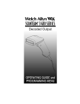
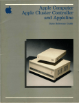
Cordless System: Main Components
Indicator
LEDs
Cordless Scanner
Left Side View
(with battery pack)
Scan
Window
Trigger
Battery
Pack Clip
(2 Places)
Battery
Pack
Antenna
Cordless Base
Back View
Keyboard/Terminal
and RS-232 Connector
(Host Port)
Aux RS-232, Service Port,
and Wand Emulation
Output Connector
1–2
Cordless Systems Manual
External Power
Connector
About the Battery Pack
Power is supplied to the Cordless Scanner by a rechargeable
battery pack that snaps onto the bottom of the scanner. Each
scanner is shipped with a battery pack [. Battery packs are
offered in a choice of Nickel Cadmium (NiCad) cells, as
an entry level solution, or a premium battery pack
based on Nickel Metal Hydride (NiMH) cells. (See
Battery Specifications, page NO TAG, for the
differences between the two types of battery packs, as
well as storage information.)
[ Order backup battery pack(s) or replacement batteries from your distributor.
North American Charging Information
The battery pack is designed to plug into any two prong North American AC
power outlet (110/120 Volt) for direct charging. You need no additional
equipment and you can recharge the pack virtually anywhere.
Worldwide Charging Information: Charge Strips
Since the battery pack is rated for both 110/120 60 Hz and 230/240 volt 50 Hz
applications it may be recharged worldwide. For international charging, to
accommodate the wide variety of electrical outlets, a custom charge strip is
required to charge the batteries. The charge strip supports both versions of
battery packs and is offered for two or six battery pack configurations.
Contact your distributor for more information or to order Charge Strips.
Battery Pack Recommendations
•
Charge the battery pack immediately before use or at least within a couple
of days of use.
•
Remove the battery pack from the power outlet or charge strip within 24
hours after charging is completed. Avoid extended overcharging.
•
Periodically fully discharge the battery pack.
•
Avoid using the battery pack in extreme temperatures. Do not use or place
the charge strip in locations that are extremely hot or cold, dusty or dirty, very
humid, or subject to vibration.
•
Do not disassemble the battery pack or the charge strip. There are no
user-serviceable parts in the battery pack or in the charge strip.
Proper Disposal of the Battery Pack
When the battery pack has reached the end of its useful life,
the batteries should be disposed of by a qualified recycler or
hazardous materials handler. Do not incinerate the battery
pack or dispose of the battery pack with general waste
materials. Contact the Product Service Department (see
page NO TAG) for recycling or disposal information.
Cordless Systems Manual
1–3
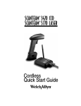
Charging Your Battery Pack
Charge the Battery Pack by following the steps shown below:
➊
Plug the battery pack directly into
any common 120 Volt AC outlet.[
To charge more than one battery pack
(or to charge the pack for all other
countries), use the Charge Strip.
➋
Cordless
Scanner
The LED on the bottom of the battery pack will
light red when the unit is charging; it shows
green when it is fully charged and ready to use.
Charge Time:
NiCad Battery Pack
8 hours at 120 VAC, 60 hz
4 hours at 220 VAC, 60 hz
5 hours at 220 VAC, 50 hz
NiHM Battery Pack
4 hours at any voltage and frequency
➌
After the battery pack is fully charged, attach it to the
Cordless Scanner by pressing the pack firmly (align
the prongs on the pack with the mating receptacles)
in the base of the scanner until the release buttons
click, holding the pack firmly in place. (When you
attach a charged battery pack to the Cordless
Scanner, you will hear a single beep.)
Rechargeable
Battery Pack
➍ If you haven’t set up your Cordless System, turn to the next page for
instructions.
When the battery pack needs recharging, the yellow LED on top of the scanner
pulses in short, continuous blinks and the scanner won’t beep when you pull the
trigger. If the LED stops flashing when the temperature lowers or you do not use
the battery pack for some time, you still need to charge the battery pack to avoid
damaging the battery pack or causing scanner memory loss.
[ Plug the battery pack into a wall socket in North America only. Failure to
comply could result in equipment failure.
1–4
Cordless Systems Manual
Setting Up and Connecting the Cordless System
Install the Base and Cordless Scanner by following the steps shown below:
Important: Make sure the Cordless Scanner’s battery pack has been fully
charged. See page 1–4 for charging instructions.
➊
Turn off the power to the host system.
➋
Connect the interface cable to the Base and to the terminal/computer (steps
1–3, shown in the illustration below). Depending on your application, the
interface cable you need may be different than the one shown below.
Keyboard Wedge Interface
Example
Terminal
(host system)
3
Cordless
Base
Disconnect
2
1
(Cable, Keyboard, and Terminal may vary.)
Note: For optimal coverage, place the Base and its antenna as far away from
other sources of RF interference, with a clear transmitting path to the scanner(s).
The Base can be mounted on a wall or a ceiling. Try to place the Base so that
the antenna is in a vertical (straight up and down) position whenever possible.
An extra Base Association Bar Code is provided in case the Base is mounted
where the label might be difficult to scan (step 4 on the next page describes the
Association process).
In an RS-232 configuration (see the illustration on the next page), connect your
interface cable between the Base unit (step 1 in the illustration) and the host
system (2). You also need to use an external power supply (3). Contact your
distributor for more information on ordering RS-232 cables or power supplies.
Cordless Systems Manual
1–5
Setting Up and Connecting the Cordless System, continued
RS-232 Interface Example
Terminal
(host system)
2
Cordless
Base
1
3
Power
Supply
(Cable, Keyboard, and Terminal may vary.)
➌
Turn on the power to the host system. Verify that the Base is on; the green
LED on top of the unit should blink. (The Base doesn’t have a beeper.)
➍
Using the Cordless Scanner, scan the Association Bar Code (the bar code
label on the top of the Base) to link that scanner to the Base (see the
illustration shown below).
Cordless CCD or
Laser Scanner
Association
Bar Code
Cordless
Base
Two quick beeps followed by a single beep (with a short delay in between) from
the scanner indicates a “good” association. The scanner is in communication
with the Base.
1–6
Cordless Systems Manual
Setting Up and Connecting the Cordless System, continued
Note: After association, if the battery pack is removed from the scanner and
replaced, the scanner will automatically re-associate to the base if the base has
remained powered up. In this case, the scanner will beep on power up and beep
a second time after full association, about five to ten seconds later.
After your Cordless Scanner has been associated with its base unit:
➎
Program your Cordless System to work with your terminal or computer by
scanning the Terminal Setup Codes. Use the Supported Terminal list
(Pages NO TAG to NO TAG) to scan your terminal’s Terminal ID.
With Plug and Play programming, you scan only one bar code to program the
Cordless System to work with a designated interface, including any required
prefixes and suffixes.
➏
To determine if your Cordless System is set up correctly, scan one of the
sample bar codes on the back cover of this manual.
Connecting More Scanners to the System
Up to nine Cordless Scanners may be associated with one Base unit [. Add
more Cordless Scanners to a Base unit by following the steps shown below:
➊
Make sure the Cordless Scanner’s battery pack has been fully charged.
➋
Scan the Association Bar Code (the bar code label on the top of the Base)
to link each scanner to the Base.
The Base stores a unique I.D. for each scanner (up to nine) to identify the
scanner during data communication. Two beeps followed by a single beep from
the scanner indicates a “good” association. The Base rejects a tenth Cordless
Scanner trying to link to its network, sending the scanner an error command. (A
rejected scanner beeps three times, indicating an unsuccessful association.)
Note: When you associate more scanners with the Base, you don’t have to
program your Cordless System to communicate with your terminal or computer
if you’ve already completed step 5, above.
[ within a 50 foot (15.24 meter) radius of the base, in an open air environment
Cordless Systems Manual
1–7
Beeper and LED Sequences and Meaning
The Base contains a green LED that indicates the status of the unit and
verification of its communication with the host system. The Cordless Scanner
contains a beeper and two LEDs on the top of the unit (green and yellow) to
indicate its power up, communication, and battery pack status. The tables below
list the indication and meaning of the beeps and LED illumination for the Base
and Cordless Scanner.
Base LED Indication
Sequence
Meaning
LED on continuously
Power on, system idle
LED blinking, long duration
Power on, diagnostic error
LED blinking, short duration
Communicating with Scanner or Host
LED blinking, four long pulses
Communication error detected
Scanner Beep Indication
Sequence
Meaning
No beep
No scanning, trigger pulled, low battery (trigger pulled)
One beep
Successful decode/communication, successful
parameter upload to the Scanner
Two beeps
Enter/exit programming mode
Three beeps
Unsuccessful communication or programming change,
unsuccessful association to Base (tenth scanner)
Scanner LED Indication
Sequence
Meaning
Green LED on
Trigger pulled
Green LED on,
five seconds
Successful decode/communication
Green LED blinks, Successful decode, unsuccessful communication, out of
five seconds
range
Yellow LED on
Scanning, trigger pulled
Yellow LED blinks, Low battery (trigger pulled), out of range
five seconds
1–8
Cordless Systems Manual
Basic Operation of the Cordless System
The following system block diagrams (on this and the following page) illustrate
the basic operating components of the Cordless System.
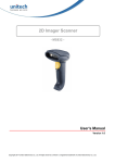
Cordless Base
The Cordless Base provides the link between the Cordless Scanner and the host
system. The Base contains a control/interface assembly and an RF
communication module. The RF communication module performs the data
exchange between the Cordless Scanner and the control/interface assembly.
The control assembly coordinates the central interface activities including:
transmitting/receiving commands and data to/from the host system, performing
software activities (parameter menuing, visual indicator support, power-on
diagnostics), and data translation required for the host system.
Cordless Base
RF Module
Control/Interface Assembly
(Base Circuit Board)
Base Housing
Control
Antenna
User I/O
Menu I/O
Host I/O
Multipoint
LED
I/O Ports
RF
Host
Power
Aux
RF (Radio Frequency) Module Operation
The Cordless System uses a state of the art radio to transmit and receive data
between the scanner and the Base. Designed for point-to-point and multipoint
to single point applications, the radio transmits data at a rate of 1 megabit per
second (MBPS) in a half duplex (2 way) communications mode. The radio
operates using a license free, low power, 2.4 GHz spread spectrum (frequency
hopping) technique. This transmission technique, which sends relatively small
data packets at a fast data rate over a radio signal with randomly changing
frequencies, makes the Cordless System highly responsive to a wide variety of
data collection applications.
The RF radio used in the Cordless System has been tested and approved as
complying with the two leading standards-setting organizations that serve as
regulatory models for compliance in most countries. In North America, the radio
is approved under the standards in FCC B Part 15.249 regulations and, in
Europe, under the standards in ETS 300 328 regulations. (See page NO TAG
for a chart of regulatory and safety agency approvals.)
Cordless Systems Manual
1–9
Cordless Scanner
The Cordless Scanner enables bar code scanning with non-contact CCD or
Laser input devices, real time decoding, and host connectivity within a 50 foot
(15.24 meter)[ radius of the Base unit. It provides the initial bar code data
acquisition function and communicates to the Base. The scanner is comprised
of a CCD or laser scan engine, a decode/control assembly, and an RF
communication module.
The scan engine performs the bar code image illumination and detection. The
decode/control assembly coordinates the central communication activities
including: capturing and decoding the bar code image data, performing software
activities (parameter menuing, visual indicator support, low battery indication),
and data translation required for the host system. The RF communication
module performs the data exchange between the scanner and the Base.
Cordless Scanner
Scanner Assembly
Engine
Assembly
Scan
Engine
(CCD or Laser)
Decode/Control Assembly
(Handle Board)
HHLC I/O
Engine Port
Control
Menu I/O
Trig/Decode
Beeper
Antenna
Engine Hsg
Window/Lt Pipe
Trigger
Handle
Housing
Power Mgmt
Beeper Port
RF Module
RF Port
Download Port
Battery Port
Battery Pack
(600 or 1.2 mh)
[ A 50 foot radius is obtained under optimal, “open air” conditions. Signals between
the Base and its scanners need a clear path to communicate, free from RF interference.
1–10
Cordless Systems Manual
Communication Between the Cordless System and the Host
The Cordless Scanner provides you with immediate feedback in the form of a
“good read” indication (a green LED on the scanner and an audible beep) after
you’ve scanned a bar code correctly and the base has acknowledged receiving
the data. The Cordless System also provides two way communication between
the Scanner and the Base or host system.
When data is scanned, the data must be accurately sent to the host system via
the Base unit. Confirmation from the host system or the Base tells you that the
data sent was received by the host. The Cordless Scanner recognizes two forms
of host confirmation: data acknowledgement (ACK) from the base unit or an
“ACK” from the host system.
Acknowledgement from the Base
If the Cordless System is configured for a keyboard wedge host interface, a
signal (ACK) is sent from the Base confirming that the data was received and is
being sent on to the host system. (Since keyboard wedge interfaces cannot
provide bi-directional communications, they do not permit host confirmation.)
1) Good Read
2) ACK from Base
3) *
* Base sends data to Host after ACK is sent to Scanner
Acknowledgement from the Host System
Host system confirmation may be implemented with a bi-directional interface like
Host RS-232. In this configuration, when the base unit receives the scanned
data from the scanner and forwards it to the host, the Cordless System waits for
a signal from the host that it received the data. (For information on enabling this
feature and using Host Escape commands, see Host Ack Selection, page
NO TAG).
2) Data to Host
1) Good Read
4) ACK from Host
(via Base)
3) ACK
Cordless Systems Manual
1–11
Accessories for the Cordless System
Several accessories are available for the Cordless System. Contact your
distributor for more information or to order accessories.
Battery Packs
Two types of battery packs are available. Each permanently sealed battery pack
contains four rechargeable “AA” cells, plus circuitry to allow recharging via
standard AC power outlets (eliminating cumbersome and expensive custom
charging stations). The entry level battery pack contains NiCad battery cells,
while the NiMH battery pack is the premium battery choice with its longer
operating and shorter charging time. Each scanner is shipped with one battery
pack. Order back up batteries or replacement batteries separately.
Charge Strips
To recharge more than one Battery Pack at one time, Charge Strips are available.
The charge strips recharge either type of battery pack (NiCad or NiMH), are
offered in two or six outlet configurations, and may be conveniently wall mounted
or set on flat surfaces. The charge strip uses a standard PC (IEC 320) grounded
power cord between the charge strip and the electrical AC outlet.
Note: International versions of the power cords are provided by Welch Allyn’s
country partners. Welch Allyn does not supply these power cords.
Belt Holster
The belt holster holds the Cordless Scanner when not in use. The belt holster
consists of a foam covered wire frame clasped to an adjustable nylon web belt
designed to be worn around the waist.
Wall Mount Kit (Standard)
The standard wall mount holder stores the Cordless Scanner on a vertical
surface for convenient access. The scanner easily slides between two
rubberized fingers that hold the scanner when it is not in use.
Wall Mount Kit (Industrial)
Similar to the standard wall mount holder, the rubberized fingers on the industrial
wall mount holder are smaller to maintain a firm grasp on the scanner under
jolting and jarring conditions, such as those expected in fork lift applications.
Visual Menu
Visual Menu is a software configuration tool that provides the ability to configure
the Cordless System by connecting the Base unit to the COM port of a PC. Visual
Menu allows you to download firmware upgrades, change programmed
parameters, and create and print programming bar codes.
1–12
Cordless Systems Manual
Section 2
Quick Start & Interface Menu
Introduction
Use this section to program the Cordless System to work with your terminal or
computer (host system).
This programming section contains the following menu selections:
•
Plug and Play
•
Terminal Interface
•
Country Code
•
Keyboard
•
Output Delays
•
Wand Emulation
•
Laser, Reset Factory Settings, and Status
All operating parameters are stored in non-volatile memory resident in the
Cordless System, where they are permanently retained in the event of a power
interruption. When you receive your Cordless System, certain operating
parameters have already been set. These are the factory defaults, indicated by
the symbol “✱” on the programming pages (beneath the default programming bar
code). Default Charts that list all the factory settings may be found near the end
of this Systems Manual.
A Programming Chart (found on the inside back cover of this manual) contains
alphanumeric bar codes for setting additional programming options, such as the
digits representing Symbology Message Length. The chart explains how and
when to use the alphanumeric bar codes.
Note: After scanning the following menu selections, there will be a pause (up
to 20 seconds) while the Base unit processes and uploads the new menuing
information to its parameter tables:
Plug and Play Selections (on the next two pages)
Factory Default Settings: ALL Application Groups (last page, Section 2)
Application Work Group Selections (Section 4)
A Sample Bar Codes page (located on the back cover of this manual) provides
bar code symbols you may scan to verify that your Cordless System has been
programmed correctly and is communicating with your host system.
Cordless Systems Manual
2–1
Industrial Interface: IBM PC
IBM PC AT and Compatibles Interface
(also PS/2 30-286, 50, 55SX, 60, 70, 70-061, 70-121, 80)
(Factory Default)
The bar code above also programs a carriage return (CR) suffix.
Industrial Interface, Aux Port: RS-232
RS-232 Interface
The bar code above also programs the following parameters:
Programmable Option
Baud Rate
Parity
Data Format
Prefix
Suffix
Setting
38,400 bits per second
None
8 data bits, 1 stop bit
None
Carriage Return (CR)
Note: Plug and Play menu codes will default all settings before programming
the interface.
2–2
Cordless Systems Manual
Industrial Interface, Aux Port: Wand Emulation
Black High
Wand Emulation (Code 39 Format) Interface
Wand Emulation (Same Code Format) Interface [
These bar codes also program the following parameters:
Programmable Option
Transmission Rate
Output Polarity
Setting
25 inches per second
Black High
Industrial Interface, Aux Port: Wand Emulation
White High
Wand Emulation (Code 39 Format) Interface
Wand Emulation (Same Code Format) Interface [
These bar codes also program the following parameters:
Programmable Option
Transmission Rate
Output Polarity
Setting
25 inches per second
White High
[ Supports Code 39, UPC, EAN, Code 128, Interleaved 2 of 5, and Codabar.
All other codes output as Code 39.
Cordless Systems Manual
2–3
If your terminal is not one of the Plug and Play options, you must program one
of the terminals listed below. To program the terminal interface, scan the
Program Terminal Interface bar code below, then scan the appropriate two digit
Terminal I.D. code and Save from the Programming Chart on the inside back
cover of this manual.
Program Terminal Interface
(Factory Default = ID 03)
Supported Terminals
Terminal
Model(s)
ADI
Bull
DEC
DEC
DEC
1496
BDS–7 Honeywell (HDS–7)
PC433 SE (Portable PC)
VT–220, 320, 330, 340, 420
VT–510, 520, 525 PC Keyboard
72
35
03
04
05
DELL
DTK
Esprit
Falco
Fujitsu
Latitude (Portable PC)
486 SLC (Portable PC)
200, 400
5220
Stylistic (Portable PC)
03
03
05
47
03
IBM
IBM
IBM
PC XT
PS/2 25, 30, 77DX2
AT, PS/2 30–286, 50, 55SX, 60, 70,
70–061, 70–121, 80
AT Compatibles Keyboard Emulation
(Non-wedge)
Thinkpad 365, 755 CV (Portable PC)
01
02
03
06
IBM 122 Key
3151, 3161, 3162, 3163, 3179, 3191,
3192, 3194, 3196, 3197, 3471, 3472,
3476, 3477, 3482, 3486, 3488
3179–1, 3191, 3192, 3471, 3472, 3194
3196, 3197, 3476, 3477, 3482, 3486,
3488
3180
IDEAssociates
IDEAssociates 102 Key
IDEAssociates 122 Key
276, 277, 486, 487, 587
276, 277, 486, 487, 587
276, 277, 486, 487, 587
08
84
71
IBM
IBM
IBM 102 Key
IBM 122 Key
IBM 122 Key
2–4
Cordless Systems Manual
Terminal I.D.
03
03
07
08
24
Supported Terminals
(Factory Default = ID 03)
Terminal
Model(s)
Lee Data
Midwest
Mitak
Olivetti
Olivetti
IIS
Micro Elite TS 30 PS (Portable PC)
4022 (Portable PC)
M19, M24, M28, M200
M240, M250, M290, M380, P500
07
03
03
01
03
Relisys
RS232 Host Port
RS232 Aux Port
Serial Wedge
Silicon Graphics
TR 175
Indy, Indigo II
03
50
00
50
05
Televideo
990, 995, 9060
Texas Instruments
Extensa 560CD (Portable PC)
Toshiba
2600 (Portable PC)
Toshiba
Satelite T1960, T2130, CS (Portable PC)
Wand Emulation Code 39 output (via Aux Port)
Wand Emulation Same Code output (via Aux Port)
Zenith
Z–note (Portable PC)
02
03
03
03
61
64
03
Cordless Systems Manual
Terminal I.D.
2–5
Keyboard Country Selection
This programming selection allows you to re-map the keyboard layout for the
selected country. As a general rule, the following characters are not supported
by the Cordless System for countries other than the United States:
@ | $ # { } [ ] = / ‘ \ < > ~
✱ United States
Belgium
Denmark, Finland, Norway, Sweden
2–6
France
Germany, Austria
United Kingdom
Switzerland
Italy
Cordless Systems Manual
Keyboard Layout Selection
This selection allows you to program the Cordless System to transmit the proper
keycodes when interfacing with a “Normal” (PC AT type), telephone, calculator,
Alpha, or Numeric keyboard layout. Choose the keyboard layout that defines
your keyboard.
✱ Layout 1 (Telephone)
Layout 2 (Calculator)
Layout 3 (PC AT)
Layout 4 (Alpha)
Layout 5 (Numeric)
Cordless Systems Manual
2–7
Keyboard Style Selections
Keyboard Style Selections
This programming selection allows you to program special keyboard features,
such as Caps Lock and Shift Lock.
Regular is used when you normally have the Caps Lock key off.
Caps Lock is used when you normally have the Caps Lock key on.
Shift Lock is used when you normally have the Shift Lock key on. (Not common
to U.S. keyboards.)
Automatic Caps Lock is used if you change the Caps Lock key on and off. The
software tracks and reflects if you have Caps Lock on or off (AT and PS/2 only).
This selection can only be used with systems that have an LED that notes the
Caps Lock status.
Emulate External Keyboard should be scanned if you do not have an external
keyboard (IBM AT or equivalent).
✱ Regular
Caps Lock
Shift Lock
Automatic Caps Lock
Emulate External Keyboard
2–8
Cordless Systems Manual
Keyboard Style Modifiers
Keyboard Style Modifiers
This programming selection allows you to program special keyboard features,
such as CTRL+ codes and Turbo Mode.
Control + ASCII Mode On – If you scan this selection, the Cordless System
sends key combinations for ASCII control characters for values 00–1F. Refer to
page NO TAG for CTRL+ Values.
Turbo Mode – Selecting Turbo Mode On, (for the IBM AT only), programs the
Cordless System to send characters to the terminal faster.
Numeric Keypad Mode – Selecting Numeric Keypad Mode On sends numeric
characters as if entered from a numeric keypad.
Automatic Direct Connect – When Emulate External Keyboard has been
selected (above), Automatic Direct Connect Mode keeps the integrated
keyboard from becoming permanently disabled. (This selection disables the
keyboard for the duration of the bar code transmission.)
Control + ASCII Mode On
✱ Control + ASCII Mode Off
Turbo Mode On
✱ Turbo Mode Off
Numeric Keypad Mode On
✱ Numeric Keypad Mode Off
Automatic Direct Connect Mode On
✱ Automatic Direct Connect Mode Off
Cordless Systems Manual
2–9
Output Delays Selection
This selection provides control of the time delays between data output by the
Cordless System to the host terminal. The actual delay is 5 milliseconds
multiplied by the programmed value (00 – 99). Default = 00.
Intercharacter Delay is the time delay between data characters output by the
Cordless System to the host terminal.
Interfunction Delay is the time delay between function (key) codes output by
the Cordless System to the host terminal.
Intermessage Delay is the time delay between data messages or records
output by the Cordless System to the host terminal.
Example: You need a 45 millisecond delay. Scan the Intercharacter Delay bar
code. Then scan “0,” “9,”and Save on the Programming Chart (09 x 5ms =
45ms).
Intercharacter Delay (x5mS) ]
Interfunction Delay (x5mS) ]
Intermessage Delay (x5mS) ]
] A two-digit number and Save are required after scanning this programming
bar code. Refer to the Programming Chart (inside back cover).
2–10
Cordless Systems Manual
Transmission Rate Selection
This programming selection sets the transmission rate from 10 ips (inches per
second) to 300 ips if the Cordless System is in Wand Emulation mode.
Programming the transmission rate causes the data to be sent at the specified
rate. The programmed transmission rate must be compatible with the device
receiving the bar code data.
10
✱ 25
40
80
120
150
200
300
Output Polarity Selection
This selection allows you to set the output logic convention for the digital output.
The choices are White High (“Laser” output) and Black High.
✱ Black High
White High
Cordless Systems Manual
2–11
Reset Factory Settings
Scanning the Factory Default Settings bar code resets the Cordless System
to the original factory settings, clearing any programming changes you may have
made. You may reset the factory default settings for the current application group
or for all application groups. Both selections will set the terminal ID to 03. Scan
the correct programming below.
Factory Default Settings: Current Application Group
Factory Default Settings: ALL Application Groups
2–12
Cordless Systems Manual
Section 3
Communications Menu
Introduction
Use this section to program the communications parameters for the Cordless
System.
This programming section contains the following menu selections:
•
Host Port Communications (RS-232)
•
Auxiliary Port Communications (RS-232)
Cordless Systems Manual
3–1
✱ Default All Host Port Communications ✱
Baud Rate Selection
This selection sets the baud rate from 300 bits per second to 38,400 bits per
second. Programming baud rate causes the data to be sent at the specified rate.
The host terminal must be set up for the same baud rate as the Cordless System
to ensure reliable communication.
300
600
1200
2400
4800
9600
✱ 38400
19200
3–2
Cordless Systems Manual
Parity Selection
This selection provides a means of checking character bit patterns for validity.
The Cordless System can be configured to operate under Even, Odd,
Mark, None, or Space parity options. The host terminal must be set up for the
same parity as the Cordless System to ensure reliable communication.
✱ None
Space
Mark
Even
Odd
Word Length Data Bits Selection
This selection sets the Word Length at seven or eight bits of data per character.
If an application requires only ASCII Hex characters 0 through 7F decimal (text,
digits, and punctuation), select 7 data bits. For applications requiring use of the
full ASCII set, select 8 data bits per character.
✱ 8 Data Bits
7 Data Bits
Cordless Systems Manual
3–3
Word Length Stop Bits Selection
This selection sets the Word Length at one or two stop bits.
✱ 1 Stop Bit
2 Stop Bits
Serial Wedge Output Selection
This selection selects the serial output direction required by your application. P1
and P2 are serial wedge designations printed on the serial wedge cable. Usually,
one goes to the host and one goes to the terminal, depending on your specific
application and the serial wedge cable.
3–4
To P1
To P1 and P2
To P2
✱ None (Host Port RS-232)
Cordless Systems Manual
Hardware Flow Control Selection
This selection enables hardware flow control that checks for a CTS signal before
sending data. This option is useful when your application supports the CTS
This selection cannot be used with Serial Wedge Output
signal. Note:
Selection.
✱ Disable
Enable
Cordless Systems Manual
3–5
Host ACK Selection
This selection programs the Cordless System to wait for a confirmation signal
(ACK) from the host after bar code data has been sent. The host system may
also be used to generate Escape Commands for user feedback (see section
below). Page 1–11 in the Getting Started Section explains how Host ACK works
and provides an illustration of the feature.
Note: Host ACK mode will only work with a host system that supports RTS/CTS
flow control. If your host system does not support RTS/CTS handshaking,
enabling Host ACK selection will cause some or all of your data to be lost.
✱ Disable
Enable
Escape Commands
The Cordless System will respond to beep and blink commands from the host
system. The format for these commands is:
Esc x (where “x” is one of the Escape commands listed below)
The table below lists the Escape commands that may be generated from the host
system and the resulting action(s).
Command
Action
Esc a
Beep/blink LED if successful programming change
Esc b
Beep/blink LED if unsuccessful programming change
Esc 1
Illuminate green LED for 135 milliseconds
Esc 2
Illuminate green LED for 2 seconds
Esc 3
Illuminate green LED for 5 seconds
Esc 4
One beep at low volume
Esc 5
One beep at medium volume
Esc 6
One beep at high volume
Esc 7
Beep/blink LED if successful decode/communication to host
Esc 8
Beep/blink LED if successful decode, unsuccessful
communication to host
3–6
Cordless Systems Manual
✱ Default All Auxiliary Port Communications ✱
Baud Rate Selection
This selection sets the baud rate from 300 bits per second to 38,400 bits per
second. Programming baud rate causes the data to be sent at the specified rate.
The device connected to the Auxiliary Port must be set up for the same baud rate
as the Aux Port to ensure reliable communication.
300
600
1200
2400
4800
9600
19200
✱ 38400
Cordless Systems Manual
3–7
Parity Selection
This selection provides a means of checking character bit patterns for validity.
The Auxiliary Port can be configured to operate under Even, Odd, Mark, None,
or Space parity options. The device connected to the Auxiliary Port must be set
up for the same parity as the Aux Port to ensure reliable communication.
✱ None
Space
Mark
Even
Odd
Word Length Data Bits Selection
This selection sets the Word Length at seven or eight bits of data per character.
If an application requires only ASCII Hex characters 0 through 7F decimal (text,
digits, and punctuation), select 7 data bits. For applications requiring use of the
full ASCII set, select 8 data bits per character.
✱ 8 Data Bits
7 Data Bits
3–8
Cordless Systems Manual
Word Length Stop Bits Selection
This selection sets the Word Length at one or two stop bits.
✱ 1 Stop Bit
2 Stop Bits
Protocol Selection
This selection programs the Auxiliary Port for the protocol required by the input
device to the Auxiliary Port. The protocol is a set of rules concerning the
exchange of data between serially communicating devices. The Auxiliary Port
supports Record, Burst, and Ack / Nak protocols when receiving data from an
RS-232 device.
✱ Record
Burst
Record Ack / Nak
Block Ack / Nak
Aux Port I.D. Transmit Selection
This will attach the Aux Port identifier (which is the letter “r”) to the incoming data
at the Auxiliary Port and will send it along with the data to the host device.
✱ Disable
Enable
Cordless Systems Manual
3–9
Hardware Flow Control Selection
This selection enables hardware flow control that checks for a CTS signal before
sending data. This option is useful when your application supports the CTS
signal.
✱ Disable
Enable
Note: The Auxiliary Port receive function will only work properly if RTS/CTS or
ACK/NAK flow control is used. If your host system does not support RTS/CTS
or ACK/NAK handshaking, some or all of your data will be lost.
Data Character Selection
This selection selects the serial output data characters that may be sent from the
RS-232 device connected to the Auxiliary Port.
Default SOR Character = none (NUL: 00).
Default EOR Character = Carriage Return (CR: 0D).
Default SOB Character = none (NUL: 00).
Default EOB Character = End of Text (EOT: 04).
SOR (Start of Record) ]
EOR (End of Record) ]
SOB (Start of Block) ]
EOB (End of Block) ]
] A two-digit number and Save are required after scanning this programming
bar code. Refer to the Programming Chart (inside back cover).
3–10
Cordless Systems Manual
Aux Prefix and Suffix
Aux Prefix and Suffix characters are data characters you may assign to incoming
Auxiliary Port data.
Data frame –>
Prefix
Message
Suffix
Characters for the Prefix and Suffix are selected by their hexadecimal ASCII
value, up to 12 characters each. Prefix and Suffix characters may be assigned
to all incoming data.
Default Prefix (incoming data) = none.
Default Suffix (incoming data) = none.
Default Prefix (outgoing data) = none.
Default Suffix (outgoing data) = Carriage Return (CR).
Programming Steps to Add an Aux Prefix / Suffix to Incoming Data:
➊
To add a Prefix, scan the Add Aux Prefix programming bar code.
To add a Suffix, scan the Add Aux Suffix programming bar code.
➋
Scan two bar codes for the Hex Value “72” (“r,” which represents the I.D.
for the Aux Port). Scan the two digits on the Programming Chart (on the
inside back cover of this manual).
➌
Refer to the Hex ASCII Chart (page 3–13) to find the Hex value that
represents the ASCII characters you wish to attach to the data. Use the
Programming Chart (inside back cover) to scan the alphanumeric
combination that represents the ASCII characters.
➍
To complete Aux Prefix / Suffix programming, scan either:
H Save Current Changes programming bar code. This exits, saving
the Prefix / Suffix selections you just assigned.
H Discard Current Changes programming bar code. This exits
without changing the Prefix / Suffix.
Other Programming Selections: Scanning the Default Prefix or Default
Suffix bar code sets the default Prefix or Suffix (shown above).
Other Programming Selections: Scanning the Clear All Prefixes or Clear All
Suffixes bar code deletes all Prefix or Suffix selections.
Note: Aux Prefix / Suffix programming examples may be found on page 3–13.
Cordless Systems Manual
3–11
Aux Prefix Selection
Add Aux Prefix ]
Clear All Prefixes (default)
Aux Suffix Selection
Add Aux Suffix ]
Clear All Suffixes (default)
Exit Selection for Aux Prefix / Suffix
Save Current Changes
Discard Current Changes
] One or more two-digit numbers and Save are required after scanning this
programming bar code. Refer to the Programming Chart (inside back cover).
3–12
Cordless Systems Manual
Aux Prefix and Suffix Examples
Example 1: Add a Prefix
To add an HT (tab) Prefix to incoming data:
H Scan the Add Aux Prefix Prefix Selection bar code.
H Scan 7 and 2 on the Programming Chart (inside back cover).
H An “HT” is equivalent to “09” (see the Hex ASCII Chart). Scan 0 and 9
on the Programming Chart.
H Scan the Save Current Changes Exit Selection bar code.
Example 2: Add a Suffix
To add a CR (carriage return) Suffix to incoming data:
H Scan the Add Aux Suffix Suffix Selection bar code.
H Scan 7 and 2 on the Programming Chart (inside back cover).
H A “CR” is equivalent to “0D” (see the Hex ASCII Chart). Scan 0 and D
on the Programming Chart.
H Scan the Save Current Changes Exit Selection bar code.
Hex to ASCII Conversion Chart
ASCII
Hex
ASCII
Hex
ASCII Hex ASCII Hex ASCII Hex ASCII Hex ASCII Hex ASCII
Hex
NUL
SOH
STX
ETX
EOT
ENQ
ACK
BEL
BS
HT
LF
VT
FF
CR
SO
SI
00
01
02
03
04
05
06
07
08
09
0A
0B
0C
0D
0E
0F
DLE
DC1
DC2
DC3
DC4
NAK
SYN
ETB
CAN
EM
SUB
ESC
FS
GS
RS
US
10
11
12
13
14
15
16
17
18
19
1A
1B
1C
1D
1E
1F
SP
!
”
#
$
%
&
’
(
)
*
+
,
–
.
/
70
71
72
73
74
75
76
77
78
79
7A
7B
7C
7D
7E
7F
20
21
22
23
24
25
26
27
28
29
2A
2B
2C
2D
2E
2F
0
1
2
3
4
5
6
7
8
9
:
;
<
=
>
?
30
31
32
33
34
35
36
37
38
39
3A
3B
3C
3D
3E
3F
@
A
B
C
D
E
F
G
H
I
J
K
L
M
N
O
40
41
42
43
44
45
46
47
48
49
4A
4B
4C
4D
4E
4F
P
Q
R
S
T
U
V
W
X
Y
Z
[
\
]
^
_
Cordless Systems Manual
50
51
52
53
54
55
56
57
58
59
5A
5B
5C
5D
5E
5F
‘
a
b
c
d
e
f
g
h
i
j
k
l
m
n
o
60
61
62
63
64
65
66
67
68
69
6A
6B
6C
6D
6E
6F
p
q
r
s
t
u
v
w
x
y
z
{
|
}
~
DEL
3–13
Aux Data Format Editor
This selection provides editing of all incoming data to the Auxiliary Port.
Scanning the Default Data Format bar code will program the Cordless System
to the default Data Format, which is none. Be certain you want to delete or clear
all formats before you scan the Default Data Format bar code. Default Data
Format = none.
To make Data Format Editor selections, you must know the terminal type,
code length, and editor commands your application requires. Use the
Alphanumeric bar codes (inside back cover) to scan these options.
Use the Aux Data Format Editor by following the steps below:
➊
➋
➌
Scan the Enter Aux Data Format bar code to start Format Editor selection.
Terminal Type
Scan two bar codes that represent the terminal type of the data’s destination
(00-99[, see page 2–4 for Terminal I.D. list.)
Code I.D.
Scan two bar codes for the Hex Value “72” (“r,” which represents the I.D. for
the Aux Port).
➍
Length
Scan four numeric bar codes (inside back cover) for the bar code length you
require (0000-9999]). Be sure to include spaces.
➎
Editor Command Sequences
Refer to the Format Editor Commands chart (page 3–16). Scan two bar
codes that represent the command you need.
➏
End Data Format Editor
Scan Save Current Changes to end Data Format Editor programming.
[ 99 is the universal terminal type, indicating all terminal types.
] 9999 is the universal length, indicating all bar code lengths.
Other Programming Selections: You may also save or discard your Data
Format changes, by scanning either:
3–14
H
Clear One Data Format programming bar code. This deletes
Data Format selections. Scan the Terminal I.D., 7 and 2, and the
length of the format you want to delete. All other formats are
unaffected.
H
Save Current Changes programming bar code. This exits, saving
the Data Format selections you just assigned.
H
Discard Current Changes programming bar code. This exits
without changing the Data Format selections.
Cordless Systems Manual
Aux Data Formatter
When Data Formatter is disabled, the incoming data will be output to the host as
received (including prefixes and suffixes).
✱ Enable
Disable
Aux Require Data Format?
When Data Formatter is required, all input data must conform to an edited format
or the Cordless System will not transmit the input data to the host device.
✱ Don’t Require
Require
Aux Data Format Editor
See pages 3–14 and 3–16 through 3–17 for a description of this selection,
commands, and examples.
✱ Default Data Format (none)
Enter Aux Data Format ]
Clear One Data Format ]
Save Current Changes
Discard Current Changes
] One or more two-digit numbers and Save are required after scanning this
programming bar code. Refer to the Programming Chart (inside back cover).
Cordless Systems Manual
3–15
Aux Format Editor Commands Chart
Send Commands
F1 Send all characters followed by “XX” key or function code, starting from
current cursor position. Syntax = F1XX (XX = HEX ASCII character or
function code 00–7F HEX).
F2 Send “NN” characters followed by “XX” key or function code, starting from
current cursor position. Syntax = F2NNXX (NN = number of characters
00–99 DEC, XX = HEX ASCII character or function code 00–7F HEX).
F3 Send up to but not including “SS” character (Search and Send) starting from
current cursor position, leaving cursor pointing to “SS” character followed
by “XX” key or function code. Syntax = F3SSXX (SS = HEX ASCII
Character 00–7F HEX, XX = HEX ASCII character 00–7F HEX).
F4 Send “XX” character “NN” times (Insert) leaving cursor in current cursor
position. Syntax = F4XXNN (XX = HEX ASCII character 00–7F HEX, NN
= number of characters 00–99 DEC).
Move Commands
F5 Move cursor ahead “NN” characters from current cursor position.
Syntax = F5NN (NN = number of characters 00–99 DEC).
F6 Move cursor back “NN” characters from current cursor position.
Syntax = F6NN (NN = number of characters 00–99 DEC).
F7 Move cursor to the beginning of the data string. Syntax = F7.
Search Commands
F8 Search ahead for “XX” character from current cursor position, leaving cursor
pointing to “XX” character. Syntax = F8XX (XX = HEX ASCII character
00–7F).
F9 Search back for “XX” character from current cursor position, leaving cursor
pointing to “XX” character. Syntax = F9XX (XX = HEX ASCII character
00–7F).
Miscellaneous Commands
FA Leading zero suppress on. Suppress leading zeroes from current cursor
position until first non–zero character. Syntax = FA.
FB Suppress “XX” character(s) (up to three) starting from current cursor
position until suppress disable command “FC” or end of format. Syntax =
FBXXFB, FBXXXXFB, FBXXXXXXFB (XX = ASCII character 00–7F).
FC Disable suppress filter and clear all suppressed characters. Syntax = FC.
FE Compare character in current cursor position to the character “XX.” If
characters are equal, increment cursor. If characters are not equal, no
format match. Syntax = FEXX (XX = HEX ASCII character 00 –7F).
3–16
Cordless Systems Manual
Aux Data Formatter Example
You are sending five digit data into the Auxiliary Port; however, your host system
can only accept data which has eight digits. You must add three zeroes to the
beginning of the Aux Port data.
Received
12345
Must send
00012345
Refer to the Aux Format Editor Commands Chart on page 3–16 to format the
following example. The programming bar codes on page 3–15, and the
alphanumeric bar codes on the inside back cover are used to program the data
formatter.
H
H
H
H
Scan the Enter Aux Data Format bar code (page 3–15).
Scan the 99 bar codes for Universal Terminal Type.
Scan the 72 bar codes, the Hex value for the Auxiliary Port.
Scan the 0005 bar codes for the data length.
The following are the Aux Editor Command Sequences:
H
H
H
Scan the F4 (send XX character NN times command) bar codes, scan 30
bar codes (the Hex value for a zero), scan 03 bar codes (send three times).
Scan the F1 and 00 bar codes to send all data followed by a NUL (NUL= 00
in Hex value).
Scan the Save bar code to end Aux Format Editor selection.
Cordless Systems Manual
3–17
Notes:
The space below may be used for notes. ...
3–18
✍
Cordless Systems Manual
Section 4
Application Work Groups Menu
Introduction
Use this section to program parameters for application work groups for the
Cordless System.
This programming section contains the following menu selections:
•
Output Selections (User Feedback)
•
Prefix and Suffix
•
Data Formatter
When you set up and connect the Cordless System to your host system, you
associate the Cordless Scanner to its Base unit. If you are using more than one
Cordless Scanner, you may also set up application work groups. (Instructions
for associating more scanners – up to nine – to the Base are on page 1–7.)
Application work groups may be set up in different configurations using the
programming selections found in this section of the manual. For example, one
group may need the beeper turned off, will only scan Code 39 bar codes, and
needs a carriage return suffix added to the data being sent to the host system
via the Base. Another group may require that scanner voting be enabled, will
scan UPC A, and needs a space added to the transmitted data, between the main
UPC bar code data and the five digit addenda.
The Application Work Groups Selection (on the next page) sets up the
application work group(s). After you’ve scanned the association bar code on the
Base, scan one of the work group numbers to assign the Cordless Scanner to
a specific group. You may then program whatever parameters your application
requires from the Output (User Feedback), Prefix and Suffix, and Data Formatter
Selections menu pages.
To add a new Cordless Scanner to an established group, associate the scanner
to the Base and scan the application work group number. The scanner will
operate and send data to the host system according to that group’s programmed
selections. Any programming selections you change or make with one Cordless
Scanner will affect all the scanners in a work group.
Note: To program a group’s parameters, you must first scan the group number
and then the programming selections (prefix, suffix, data formatter, etc.). The
parameters can’t be programmed first and then “made” a group by scanning an
application work group number.
To remove a scanner associated with a Base unit, use the Remove Scanner
Selection on page 4–3. For instance, if nine scanners are associated with a
Base (the maximum number) and you want to add a new scanner, you will need
to remove one scanner from the established work groups. After removing one
scanner by using the Remove Scanner programming bar code, add the new
scanner by scanning the association bar code on the Base unit.
Cordless Systems Manual
4–1
Application Work Group Selection
This programming selection sets up application work groups sharing specific
programming settings (such as Beeper Volume, Scanner Voting, Prefix / Suffix,
and Data Formatter). Scan the group number and then program the selections
your application requires. (Refer to the introduction, page 4–1, for more
information on application work groups.)
✱ Group 0
Group 1
Group 2
Group 3
Group 4
Group 5
Group 6
Group 7
Group 8
4–2
Cordless Systems Manual
Remove Scanner Selection
This programming selection removes a scanner from an associated Base unit.
Remove Scanner
Beeper Volume Selection
Low
Off
✱ High
Medium
Scanner Voting Selection
When Scanner Voting is enabled, the Cordless System requires three (3)
identical, consecutive scans before the bar code data will be accepted and
transmitted to the terminal. When this selection is disabled, the bar code data
will be transmitted following one (1) valid scan.
✱ Disable
Enable
Cordless Systems Manual
4–3
Laser Marker Beam
When enabled, the Cordless Scanner shows a marker or locator beam before
the red scan line opens across a bar code and the scanning process begins. The
marker beam, emitted by centering the optical scan mirror, appears as a bright
spot of illumination that serves as an aiming guide when bar code targets are at
a distance from the scanner. Note:Applies only to the 5770LR product. If this
selection is enabled on non-5770LR products, the scan rate is diminished.
✱ Disable
Enable
AIM I.D. Transmit Selection
This selection enables or disables transmission of an AIM I.D. before the
decoded bar code symbology. (The Symbology Chart on page 4–8 shows the
single AIM[ character code that identifies each symbology. For more
information, see AIM Guidelines on Symbology Identifiers.)
✱ Disable
Enable
[ Automatic Identification Manufacturers Inc., a trade association, located at
634 Alpha Drive, Pittsburg, PA 15238–2802.
Welch Allyn Code I.D. Transmit Selection
This selection enables or disables transmission of a Welch Allyn Code I.D. before
the decoded bar code symbology. (See the Symbology Chart on page 4–8 for
the single character code that identifies each symbology.)
✱ Disable
Enable
4–4
Cordless Systems Manual
Prefix and Suffix
The Cordless System transmits a decoded message after every successful bar
code read. Prefix and Suffix characters are data characters you may assign to
be sent before and after the transmitted bar code data.
Transmitted data frame –>
Prefix
Bar Code Message
Suffix
Characters for the Prefix and Suffix are selected by their hexadecimal ASCII
value, up to 12 characters each. Prefix and Suffix characters may be sent for a
specific symbology, or may be sent with all bar code scans.
Default Prefix = none.
Default Suffix = Carriage Return (CR: 0D).
Programming Steps to Add a Prefix / Suffix:
➊
To add a Prefix, scan the Add Prefix programming bar code.
To add a Suffix, scan the Add Suffix programming bar code.
➋
Refer to the Symbology Chart (page 4–8) to find the Hex value that
represents the symbology(s) you want transmitted with one or more
Prefixes or Suffixes. Scan the two digits on the Programming Chart (on
the inside of the back cover of this manual).
➌
Refer to the Hex ASCII Chart (page 4–8) to find the Hex value that
represents the ASCII characters you wish to transmit with the bar code
data. Use the Programming Chart (inside back cover) to scan the
alphanumeric combination that represents the ASCII characters.
➍
To complete Prefix / Suffix programming, scan either:
H Save Current Changes programming bar code. This exits, saving
the Prefix / Suffix selections you just assigned.
H Discard Current Changes programming bar code. This exits
without changing the Prefix / Suffix.
Programming Steps to Clear (or Delete) One or All Prefix / Suffix Entry:
➊
➋
➌
To clear all the Prefix entries for a specific symbology, scan the Clear
One Prefix programming bar code.
To clear all the Suffix entries for a specific symbology, scan the Clear
One Suffix programming bar code.
Refer to the Symbology Chart to find the Hex value representing the
symbology’s entry you want cleared. Scan the two digits on the
Programming Chart (on the inside of the back cover of this menu).
Scan Save Current Changes or Discard Current Changes
programming bar codes to complete programming.
Other Programming Selections: Scanning the Default Prefix or Default
Suffix bar code sets the default Prefix or Suffix (shown above).
Other Programming Selections: Scanning the Clear All Prefixes or Clear All
Suffixes bar code deletes all Prefix or Suffix selections.
Note: Prefix / Suffix programming examples may be found on page 4–7.
Cordless Systems Manual
4–5
Prefix Selection
Add Prefix ]
Default Prefix (none)
Clear One Prefix ]
Clear All Prefixes
Suffix Selection
Add Suffix ]
Default Suffix (CR)
Clear One Suffix ]
Clear All Suffixes
Exit Selection for Prefix / Suffix
Save Current Changes
Discard Current Changes
] One or more two-digit numbers and Save are required after scanning this
programming bar code. Refer to the Programming Chart (inside back cover).
4–6
Cordless Systems Manual
Prefix and Suffix Examples
Example 1: Add Suffix for Specific Symbology
To send a CR (carriage return) Suffix for UPC only.
H Scan the Add Suffix Suffix Selection bar code.
H The Symbology Chart indicates that the Hex value of UPC is “63”. Scan
6 and 3 on the Programming Chart (inside back cover).
H A “CR” is equivalent to “0D” (see the Hex ASCII Chart). Scan 0 and D
on the Programming Chart.
H Scan the Save Current Changes Exit Selection bar code.
Example 2: Add Suffix for ALL Symbologies
To send a CR (carriage return) Suffix for all symbologies.
H Scan the Add Suffix Suffix Selection bar code.
H The Symbology Chart indicates that the Hex value for All Symbologies
is “99”. Scan 9 and 9 on the Programming Chart.
H A “CR” is equivalent to “0D”. Scan 0 and D on the Programming Chart.
H Scan the Save Current Changes Exit Selection bar code.
Example 3: Add Prefix for Specific Symbology / Suffix for ALL Symbologies
To send an HT (tab) Prefix for UPC only and a CR / LF (carriage return / line
feed) Suffix for all symbologies.
H Scan the Add Prefix Prefix Selection bar code.
H The Symbology Chart indicates that the Hex value of UPC is “63”. Scan
6 and 3 on the Programming Chart.
H An “HT” is equivalent to “09”. Scan 0 and 9 on the Programming Chart.
H Scan the Add Suffix Suffix Selection bar code.
H The Symbology Chart indicates that the Hex value for All Symbologies
is “99”. Scan 9 and 9 on the Programming Chart.
H A “CR” is equivalent to “0D” and an “LF” is “0A”. Scan 0, D, 0, and A on
the Programming Chart.
H Scan the Save Current Changes Exit Selection bar code.
Example 4: To Clear a Specific Prefix Entry
The Cordless System is programmed to send a CR / LF (carriage return / line
feed) Prefix for all symbologies (Hex value, 99). This is one Prefix entry. You’ve
also programmed a “#” Prefix for UPC (Hex, 63). To clear the UPC entry, but not
the Prefix entry for all symbologies.
H Scan the Clear Specific Prefix Prefix Selection bar code.
H The Symbology Chart indicates that the Hex value for UPC is “63”. Scan
6 and 3 on the Programming Chart.
H Scan the Save Current Changes Exit Selection bar code.
Cordless Systems Manual
4–7
Symbology Chart
AIM Code Hex
Symbology
ID
ID Value
Symbology
AIM
ID
Code Hex
Value
ID
Codabar
]F0
a
61
Code 11
]H0
h
68
Code 39
]A0
b
62
Code 93
]G0
i
69
UPC
]E0
c
63
Code 128
]C0
j
6A
EAN
Interleaved 2 of 5
]E0
]I0
d
e
64
65
Matrix 2 of 5
]X0
All Symbologies
m
6D
99
Code 2 of 5
]S0
f
66
(Prefix/Suffix Programming only.)
Hex to ASCII Conversion Chart
ASCII
Hex
ASCII
Hex
ASCII Hex ASCII Hex ASCII Hex ASCII Hex ASCII Hex ASCII
Hex
NUL
SOH
STX
ETX
EOT
ENQ
ACK
BEL
BS
HT
LF
VT
FF
CR
SO
SI
00
01
02
03
04
05
06
07
08
09
0A
0B
0C
0D
0E
0F
DLE
DC1
DC2
DC3
DC4
NAK
SYN
ETB
CAN
EM
SUB
ESC
FS
GS
RS
US
10
11
12
13
14
15
16
17
18
19
1A
1B
1C
1D
1E
1F
SP
!
”
#
$
%
&
’
(
)
*
+
,
–
.
/
70
71
72
73
74
75
76
77
78
79
7A
7B
7C
7D
7E
7F
20
21
22
23
24
25
26
27
28
29
2A
2B
2C
2D
2E
2F
0
1
2
3
4
5
6
7
8
9
:
;
<
=
>
?
30
31
32
33
34
35
36
37
38
39
3A
3B
3C
3D
3E
3F
@
A
B
C
D
E
F
G
H
I
J
K
L
M
N
O
40
41
42
43
44
45
46
47
48
49
4A
4B
4C
4D
4E
4F
P
Q
R
S
T
U
V
W
X
Y
Z
[
\
]
^
_
50
51
52
53
54
55
56
57
58
59
5A
5B
5C
5D
5E
5F
‘
a
b
c
d
e
f
g
h
i
j
k
l
m
n
o
60
61
62
63
64
65
66
67
68
69
6A
6B
6C
6D
6E
6F
p
q
r
s
t
u
v
w
x
y
z
{
|
}
~
DEL
Note: Prefix / Suffix entries for specific symbologies override the universal (All
Symbologies, 99) entry.
4–8
Cordless Systems Manual
Data Format Editor
This selection provides editing of all input (scanned) data. All Industrial and
Retail symbologies can be formatted. Scanning the Default Data Format bar
code will program the Cordless System to the default Data Format, which is
none. Be certain you want to delete or clear all formats before you scan the
Default Data Format bar code. Default Data Format = none.
To make Data Format Editor selections, you must know the terminal type,
code I.D., code length, and editor commands your application requires. Use
the Alphanumeric bar codes (inside back cover) to scan these options.
Use the Data Format Editor by following the steps below:
➊
➋
➌
Scan the Enter Data Format bar code to start Format Editor selection.
Terminal Type
Scan two bar codes that represent the terminal type (00-99[, see page 2–4
for Terminal I.D. list.)
Code I.D.
Refer to the Symbology chart (page 4–8), then scan two bar codes from
the “Hex Value” column that represent the Code I.D. of the symbology you
want formatted. (“All Symbologies” – hex value 99 – is not supported by
Data Formatter.)
➍
Length
Scan four numeric bar codes (inside back cover) for the bar code length you
require (0000-9999]). Be sure to include spaces.
➎
Editor Command Sequences
Refer to the Format Editor Commands chart (page 4–11). Scan two bar
codes that represent the command you need.
➏
End Data Format Editor
Scan Save Current Changes to end Data Format Editor programming.
[ 99 is the universal terminal type, indicating all terminal types.
] 9999 is the universal length, indicating all bar code lengths.
Other Programming Selections: You may also clear, save or discard your Data
Format changes, by scanning either:
H
Clear One Data Format programming bar code. This deletes
Data Format selections. Scan the Terminal I.D., Code I.D. and the
length of the format you want to delete. All other formats are
unaffected.
H
Clear All Data Formats programming bar code. This deletes all
Data Format selections.
H
Save Current Changes programming bar code. This exits, saving
the Data Format selections you just assigned.
H
Discard Current Changes programming bar code, found on the
Programming Chart (inside back cover). This exits without
changing the Data Format selections.
Cordless Systems Manual
4–9
Data Formatter
When Data Formatter is disabled, the bar code data will be output to the host as
read (including prefixes and suffixes).
✱ Enable
Disable
Require Data Format?
When Data Formatter is required, all input data must conform to an edited format
or the Cordless System will not transmit the input data to the host device.
✱ Don’t Require
Require
Data Format Editor
See pages 4–9 and 4–11 through 4–12 for a description of this selection,
commands, and examples.
✱ Default Data Format (none)
Enter Data Format ]
Clear One Data Format ]
Save Current Changes
Clear All Data Formats
] One or more two-digit numbers and Save are required after scanning this
programming bar code. Refer to the Programming Chart (inside back cover).
4–10
Cordless Systems Manual
Format Editor Commands Chart
Send Commands
F1 Send all characters followed by “XX” key or function code, starting from
current cursor position. Syntax = F1XX (XX = HEX ASCII character or
function code 00–7F HEX).
F2 Send “NN” characters followed by “XX” key or function code, starting from
current cursor position. Syntax = F2NNXX (NN = number of characters
00–99 DEC, XX = HEX ASCII character or function code 00–7F HEX).
F3 Send up to but not including “SS” character (Search and Send) starting from
current cursor position, leaving cursor pointing to “SS” character followed
by “XX” key or function code. Syntax = F3SSXX (SS = HEX ASCII
Character 00–7F HEX, XX = HEX ASCII character 00–7F HEX).
F4 Send “XX” character “NN” times (Insert) leaving cursor in current cursor
position. Syntax = F4XXNN (XX = HEX ASCII character 00–7F HEX, NN
= number of characters 00–99 DEC).
Move Commands
F5 Move cursor ahead “NN” characters from current cursor position.
Syntax = F5NN (NN = number of characters 00–99 DEC).
F6 Move cursor back “NN” characters from current cursor position.
Syntax = F6NN (NN = number of characters 00–99 DEC).
F7 Move cursor to the beginning of the data string. Syntax = F7.
Search Commands
F8 Search ahead for “XX” character from current cursor position, leaving cursor
pointing to “XX” character. Syntax = F8XX (XX = HEX ASCII character
00–7F).
F9 Search back for “XX” character from current cursor position, leaving cursor
pointing to “XX” character. Syntax = F9XX (XX = HEX ASCII character
00–7F).
Miscellaneous Commands
FA Leading zero suppress on. Suppress leading zeroes from current cursor
position until first non–zero character. Syntax = FA.
FB Suppress “XX” character(s) (up to three) starting from current cursor
position until suppress disable command “FC” or end of format. Syntax =
FBXXFB, FBXXXXFB, FBXXXXXXFB (XX = ASCII character 00–7F).
FC Disable suppress filter and clear all suppressed characters. Syntax = FC.
FE Compare character in current cursor position to the character “XX.” If
characters are equal, increment cursor. If characters are not equal, no
format match. Syntax = FEXX (XX = HEX ASCII character 00 –7F).
Cordless Systems Manual
4–11
Data Formatter Example
You are using an IBM PC AT and are scanning a UPC A bar code with a five digit
addenda (shown below). The bar code has a total of 18 characters, including the
number system, the check digits, and a space between the main bar code data
and the addenda bar code data.
UPC A with 5 digit addenda
56098
0 12345 67890 5
For your application, you don’t want the space between the main bar code data
and the addenda bar code data transmitted. You also want the bar code data
followed by a carriage return (CR).
Refer to the Format Editor Commands Chart on page 4–11 to format the
following example. The programming bar codes on page 4–10, and the
alphanumeric bar codes on the inside back cover are used to program the data
formatter.
H
H
H
H
Scan the Enter Data Format bar code (page 4–10).
Scan the 03 bar codes for PC AT Terminal Type.
Scan the 63 bar codes, the Hex value for UPC symbology.
Scan the 0018 bar codes for the bar code length.
The following are the Editor Command Sequences:
H
H
H
H
Scan the FB (suppress characters command) bar codes, scan 20 (the Hex
value for a space), and then scan FB to frame (complete) the command.
Scan the F7 bar codes to move the cursor back to the beginning of the bar
code data.
Scan the F1 and 0D bar codes to send all the characters followed by a
carriage return (CR= 0D in Hex value).
Scan the Save bar code to end Format Editor selection.
4–12
Cordless Systems Manual
Section 5
Symbology Menu
Introduction
Use this section to program the Cordless System for Industrial and Retail
Symbology selections.
This programming section contains the following menu selections:
•
Matrix 2 of 5
•
Codabar
•
Code 11
•
Code 39
•
Code128
•
Code 93
•
EAN
•
Interleaved 2 of 5
•
UPC
•
Code 2 of 5
Programming Tip: If a symbology will not be used, we recommend turning it
off to maximize the Cordless System’s decoding speed.
Cordless Systems Manual
5–1
✱ Default All Codabar Settings ✱
Codabar Selection
✱ On
Codabar
Off
Transmit
Start / Stop
Characters
✱ Don’t Transmit
Minimum ]
Message
Length
Maximum ]
] A two-digit number and Save are required after scanning this programming
bar code. Refer to the Programming Chart (inside back cover).
5–2
Cordless Systems Manual
Codabar Selection, continued
Validate
Check Character
✱ Don’t Validate
Transmit
Check Character
✱ Don’t Transmit
Concatenation
Codabar supports symbol concatenation. When you Enable concatenation, the
reader will look for a Codabar symbol having a “D” start character, adjacent to
a symbol having a “D” stop character. In this case the two messages are
concatenated into one with the “D” characters omitted.
Character: Start
Stop Start
Stop
Codabar
A12D
D34A
Select Require to prevent the reader from decoding a lone Codabar symbol.
✱ Enable
Concatenation
Disable
Require
Concatenation
✱ Don’t Require
Cordless Systems Manual
5–3
✱ Default All Code 39 Settings ✱
Code 39 Selection
✱ On
Code 39
Off
Transmit
Start / Stop
Characters
✱ Don’t Transmit
Minimum ]
Message
Length
Maximum ]
Validate
Check
Character
✱ Don’t Validate
Transmit
Check
Character
✱ Don’t Transmit
] A two-digit number and Save are required after scanning this programming
bar code. Refer to the Programming Chart (inside back cover).
5–4
Cordless Systems Manual
Code 39 Selection, continued
Full ASCII
✱ Enable
Disable
Append
Enable
✱ Disable
FULL ASCII CHART [
NUL
SOH
STX
ETX
EOT
ENQ
ACK
BEL
BS
HT
LF
VT
FF
CR
SO
SI
%U
$A
$B
$C
$D
$E
$F
$G
$H
$I
$J
$K
$L
$M
$N
$O
DLE
DC1
DC2
DC3
DC4
NAK
SYN
ETB
CAN
EM
SUB
ESC
FS
GS
RS
US
$P
$Q
$R
$S
$T
$U
$V
$W
$X
$Y
$Z
%A
%B
%C
%D
%E
SP
!
”
#
$
%
&
’
(
)
*
+
,
–
.
/
SPACE
/A
/B
/C
/D
/E
/F
/G
/H
/I
/J
/K
/L
–
.
/O
0
1
2
3
4
5
6
7
8
9
:
;
<
=
>
?
0
1
2
3
4
5
6
7
8
9
/Z
%F
%G
%H
%I
%J
@
A
B
C
D
E
F
G
H
I
J
K
L
M
N
O
%V
A
B
C
D
E
F
G
H
I
J
K
L
M
N
O
P
Q
R
S
T
U
V
W
X
Y
Z
[
\
]
^
_
P
Q
R
S
T
U
V
W
X
Y
Z
%K
%L
%M
%N
%O
‘
a
b
c
d
e
f
g
h
i
j
k
l
m
n
o
%W
+A
+B
+C
+D
+E
+F
+G
+H
+I
+J
+K
+L
+M
+N
+O
p
q
r
s
t
u
v
w
x
y
z
{
|
}
~
DEL
+P
+Q
+R
+S
+T
+U
+V
+W
+X
+Y
+Z
%P
%Q
%R
%S
%T
[ This chart is used for encoding the above characters in Full ASCII when using Code
39 bar codes. For example, to get a “<”, encode %G into the bar code symbol.
Cordless Systems Manual
5–5
✱ Default All Code 93 Settings ✱
Code 93 Selection
✱ On
Minimum ]
Code 93
Message
Length
Off
Maximum ]
] A two-digit number and Save are required after scanning this programming
bar code. Refer to the Programming Chart (inside back cover).
5–6
Cordless Systems Manual
✱ Default All Interleaved 2 of 5 Settings ✱
Interleaved 2 of 5 Selection
✱ On
Minimum ]
Interleaved
2 of 5
Message
Length
Off
Maximum ]
Validate
Check Digit
✱ Don’t Validate
Transmit
Check Digit
✱ Don’t Transmit
Enable
Lengths of
6, 14 or 16
✱ Disable
] A two-digit number and Save are required after scanning this programming
bar code. Refer to the Programming Chart (inside back cover).
Cordless Systems Manual
5–7
✱ Default All Code 2 of 5 /Matrix Settings ✱
Code 2 of 5 Selection
✱ On
Minimum ]
Code
2 of 5
Message
Length
Off
Maximum ]
Matrix 2 of 5 Selection
✱ On
Minimum ]
Matrix
2 of 5
Message
Length
Off
Maximum ]
] A two-digit number and Save are required after scanning this programming
bar code. Refer to the Programming Chart (inside back cover).
5–8
Cordless Systems Manual
✱ Default All Code 11 / Code 128 Settings ✱
Code 11 Selection
✱ On
Code 11
Off
✱ 2 Check Digits
Check Digits
Required
1 Check Digit
Minimum ]
Message
Length
Maximum ]
Code 128 Selection
✱ On
Minimum ]
Code 128
Message
Length
Off
Maximum ]
] A two-digit number and Save are required after scanning this programming
bar code. Refer to the Programming Chart (inside back cover).
Cordless Systems Manual
5–9
✱ Default All EAN / JAN 8 Settings ✱
✱ Default All EAN / JAN 13 Settings ✱
EAN / JAN 8 / 13 Selection
5–10
✱ On
EAN /
JAN 8
Off
✱ On
EAN /
JAN 13
Off
✱ Transmit
Check
Digit
Don’t Transmit
Cordless Systems Manual
✱ Default All UPC A Settings ✱
UPC A Selection
✱ On
UPC A
Off
✱ Transmit
Check
Digit
Don’t Transmit
✱ Transmit
Number
System
Don’t Transmit
Cordless Systems Manual
5–11
✱ Default All UPC E0 Settings ✱
UPC E0 Selection
✱ On
UPC E0
Off
✱ Transmit
Check
Digit
Don’t Transmit
✱ Transmit
Number
System
Don’t Transmit
Expand
Version E
Expand
✱ Don’t Expand
UPC E1 Selection
On
5–12
UPC E1
Cordless Systems Manual
✱ Off
EAN / UPC Addenda Selection
Require
EAN/UPC
Addenda
✱ Don’t Require
EAN Addenda Selection
Enable
Two Digit
Addenda
✱ Disable
Enable
Five Digit
Addenda
✱ Disable
UPC Addenda Selection
Enable
Two Digit
Addenda
✱ Disable
Enable
Five Digit
Addenda
✱ Disable
Cordless Systems Manual
5–13
Notes:
The space below may be used for notes. ...
5–14
✍
Cordless Systems Manual
Section 6
Supported Interface Keys
Keyboard Function Relationships
The following Keyboard Function Code, Hex/ASCII Value, and Full ASCII
“CTRL”+ relationships apply to all terminals that can be used with the Cordless
System.
Function Code
NUL
SOH
STX
ETX
EOT
ENQ
ACK
BEL
BS
HT
LF
VT
FF
CR
SO
SI
DLE
DC1
DC2
DC3
DC4
NAK
SYN
ETB
CAN
EM
SUB
ESC
FS
GS
RS
US
HEX/ASCII Value
00
01
02
03
04
05
06
07
08
09
0A
0B
0C
0D
0E
0F
10
11
12
13
14
15
16
17
18
19
1A
1B
1C
1D
1E
1F
Full ASCII “CTRL” +
2
A
B
C
D
E
F
G
H
I
J
K
L
M
N
O
P
Q
R
S
T
U
V
W
X
Y
Z
[
\
]
6
-
The last five characters in the Full ASCII “CTRL”+ column ( [ \ ] 6 - ), apply to US
only. The following chart indicates the equivalents of these five characters for
different countries.
Country
Codes
]
6
United States
[
\
]
6
Belgium
[
<
9
6
Scandinavia
8
<
$
6
France
=
^
8
+
6
Germany
Ã
+
6
Italy
\
..
6
Swiss
<
]
6
United Kingdom
[
i
9
6
Denmark
8
\
9
6
Norway
8
\
]
6
Spain
[
\
Cordless Systems Manual
6–1
Supported Interface Keys
Supported
Interface Keys
IBM AT/XT and
PS/2 Compatibles, IBM XTs and
Compatibles
WYSE PC/AT
NUL
SOH
STX
ETX
EOT
ENQ
ACK
BEL
BS
HT
LF
VT
FF
CR
SO
SI
DLE
DC1
DC2
DC3
DC4
NAK
SYN
ETB
CAN
EM
SUB
ESC
FS
GS
RS
US
Reserved
Enter (KP)
Cap Lock
ALT make
ALT break
CTRL make
CTRL break
CR/Enter
Reserved
Tab
Reserved
Tab
Delete
CR/Enter
Insert
Escape
F11
Home
Print
Back Space
Back Tab
F12
F1
F2
F3
F4
F5
F6
F7
F8
F9
F10
00
01
02
03
04
05
06
07
08
09
0A
0B
0C
0D
0E
0F
10
11
12
13
14
15
16
17
18
19
1A
1B
1C
1D
1E
1F
Reserved
CR/Enter
Caps Lock
Reserved
Reserved
Reserved
Reserved
CR/Enter
Reserved
Tab
Reserved
Tab
Delete
CR/Enter
Insert
Escape
Reserved
Home
Print
Back Space
Back Tab
Reserved
F1
F2
F3
F4
F5
F6
F7
F8
F9
F10
* Terminal IDs 06, 07, 08 and Telex (all models)
6–2
Cordless Systems Manual
IBM, Telex*
Reserved
Enter
F11
F12
F13
F14
F15
New Line
F16
F17
F18
Tab/Field Forward
Delete
Field Exit/New Line
Insert
F19
Error Reset
Home
F20
Back Space
Backfield/Back Tab
F21
F1
F2
F3
F4
F5
F6
F7
F8
F9
F10
Supported Interface Keys
Supported
Interface Keys
IBM, Telex (102)*
Telex (88)**
DEC VT
NUL
SOH
STX
ETX
EOT
ENQ
ACK
BEL
BS
HT
LF
VT
FF
CR
SO
SI
DLE
DC1
DC2
DC3
DC4
NAK
SYN
ETB
CAN
EM
SUB
ESC
FS
GS
RS
US
Reserved
Enter
F11
F12
F13
F14
F15
New Line
F16
F17
F18
Tab/Field Forward
Delete
Field Exit
Insert
Clear
Error Reset
Home
Print
Back Space
Back Tab
F19
F1
F2
F3
F4
F5
F6
F7
F8
F9
F10
Reserved
Enter
PF10
PF11
PF12
Reserved
Reserved
New Line
Field Forward
Field Forward
Reserved
Field Forward
Delete
New Line
Insert
Erase
Error Reset
Reserved
Print
Back Space
Back Field
Reserved
PF1
PF2
PF3
PF4
PF5
PF6
PF7
PF8
PF9
Home
Reserved
Enter
PF1
PF2
PF3
PF11
PF12
New Line
PF4
TAB
F13
F14
Remove
New Line
Insert Here
Cursor Up
Cursor Left
Cursor Down
Cursor Right
Delete
Print
F15
F1
F2
F3
F4
F5
F6
F7
F8
F9
F10
00
01
02
03
04
05
06
07
08
09
0A
0B
0C
0D
0E
0F
10
11
12
13
14
15
16
17
18
19
1A
1B
1C
1D
1E
1F
* Terminal IDs 06, 07, and 08, Telex (all models) with 102 key keyboards
** Memorex Telex with 88 key keyboards
*** DEC VT 220/320/340/420
Cordless Systems Manual
6–3
Supported Interface Keys
Esprit 200, 400
Supported
Interface Keys
ANSI
NUL
SOH
STX
ETX
EOT
ENQ
ACK
BEL
BS
HT
LF
VT
FF
CR
SO
SI
DLE
DC1
DC2
DC3
DC4
NAK
SYN
ETB
CAN
EM
SUB
ESC
FS
GS
RS
US
6–4
00
01
02
03
04
05
06
07
08
09
0A
0B
0C
0D
0E
0F
10
11
12
13
14
15
16
17
18
19
1A
1B
1C
1D
1E
1F
Reserved
New Line
N/A
N/A
N/A
N/A
N/A
New Line
N/A
Tab
N/A
Tab
N/A
New Line
N/A
Escape
F11
Insert
F13
Back Space
Back Tab
F12
F1
F2
F3
F4
F5
F6
F7
F8
F9
F10
Esprit 200, 400
ASCII
Esprit 200, 400
PC
Reserved
New Line
N/A
N/A
N/A
N/A
N/A
New Line
N/A
Tab
N/A
Tab
N/A
New Line
N/A
Escape
F11
Insert
F13
Back Space
Back Tab
F12
F1
F2
F3
F4
F5
F6
F7
F8
F9
F10
Reserved
New Line
N/A
N/A
N/A
N/A
N/A
New Line
N/A
Tab
N/A
Tab
Delete
New Line
Insert
Escape
F11
Home
Print
Back Space
Back Tab
F12
F1
F2
F3
F4
F5
F6
F7
F8
F9
F10
Cordless Systems Manual
Supported Interface Keys
Supported
Interface Keys
Bull BDS–7
(Honeywell
HDS–7)
NUL
SOH
STX
ETX
EOT
ENQ
ACK
BEL
BS
HT
LF
VT
FF
CR
SO
SI
DLE
DC1
DC2
DC3
DC4
NAK
SYN
ETB
CAN
EM
SUB
ESC
FS
GS
RS
US
Reserved
Transmit
Reserved
Reserved
Reserved
Backtab
Reserved
Carriage Return
Back Space
Tab
F11
F12
Delete Character
Carriage Return
Insert
Clear
Error Reset
Home
Delete Line
Erase EOP
Erase EOF
Insert Line
F1
F2
F3
F4
F5
F6
F7
F8
F9
F10
00
01
02
03
04
05
06
07
08
09
0A
0B
0C
0D
0E
0F
10
11
12
13
14
15
16
17
18
19
1A
1B
1C
1D
1E
1F
Cordless Systems Manual
6–5
Notes:
The space below may be used for notes. ...
6–6
✍
Cordless Systems Manual
Section 7
Product Specifications
SCANTEAM 2070 Cordless Base Product Specifications
Parameter
Specification
Dimensions
Height
Width
Length
1.4 inches (3.6 cm)
4.0 inches (10.2 cm)
4.5 inches (11.5 cm)
Weight
7.25 ounces (206 g) without cable
LED Indicators
One (1)
Beeper
None
Operating Voltage
+4.0 to 14.0 VDC
Power Consumption
325 mA (typical) @ 5 VDC
Noise Immunity
100 mV peak to peak
Temperature Ranges
Operating: –4° F to +122° F (–20° C to +50° C)
Storage: –40° F to +158° F (–40° C to +70° C)
Humidity
0 to 95% relative humidity (non-condensing)
Housing Material
GE Cycloloy C2800 or C2950 Standard Flow
Sealing
IP 53 (Water and Dust Resistant)
Mechanical Shock
26 drops from 4 feet (1.2 m) to concrete
ESD Sensitivity
15 kV to any external surface
Reliability
MTBF = 50,000 hours (ground benign)
Radio Specifications
Parameter
Specification
Frequency
2.400 to 2.4835 Ghz (ISM Band) Frequency Hopping Carrier
Data Rates
1 Mbps
Cordless Systems Manual
7–1
SCANTEAM 3470 Cordless CCD Scanner Product Specifications
Parameter
Specification
Dimensions
Height
Width
Length
8.3 inches (21 cm) (with battery)
3.1 inches (7.8 cm)
4.7 inches (11.9 cm)
Weight
18 ounces (510 g) with battery pack
Light Source
630 to 660 nm Visible Red Light Emitting Diodes (LED)
Print Contrast
Minimum Reflective Difference = 37.5%
Scan Rate
113 scans per second (CCD scan engine)
LED Indicators
Two (2)
Beeper
Yes (volume programmable)
Skew Angle
±30 degrees (from perpendicular)
Pitch Angle
±7 degrees (left/right from perpendicular)
Operating Voltage
+4.3 to 6.0 VDC
Power Consumption
Operating: 400 mA (maximum) @ 4.8 VDC
210 mA (typical) while scanning
Standby: 12 mA
Ambient Light
Total darkness to 100,000 Lux (sunlight)
Noise Immunity
100 mV peak to peak
Temperature Ranges
Operating: +32° F to +122° F (–0° C to +50° C)
Storage: –22° F to +158° F (–30° C to +70° C)
Humidity
5 to 95% relative humidity (non-condensing)
Altitude
Sea level to 9,900 feet (3000 meters)
Housing Material
GE Cycloloy C2800 or C2950 Standard Flow
Sealing
IP 54 (Water and Dust Resistant)
Mechanical Shock
26 drops from 6 feet (1.8 m) to concrete
ESD Sensitivity
15 kV to any external surface
Reliability
MTBF = TBD hours (ground benign)
7–2
Cordless Systems Manual
SCANTEAM 5770 Cordless Laser Scanner Product Specifications
Parameter
Specification
Dimensions
Height
Width
Length
8.3 inches (21 cm) (with battery)
3.1 inches (7.8 cm)
4.7 inches (11.9 cm)
Weight
18 ounces (510 g) with battery pack
Light Source
630 to 670 nm Visible Laser Diode (VLD)
Scan Rate
34 scans per second (laser scan engine)
Print Contrast
Minimum Reflective Difference = 40%
LED Indicators
Two (2)
Beeper
Yes (volume programmable)
Skew Angle
±65 degrees (from perpendicular): 5770/STD
±60 degrees (from perpendicular): 5770/LR
Pitch Angle
±55 degrees (left/right from perpendicular): 5770/STD
±65 degrees (left/right from perpendicular): 5770/LR
Operating Voltage
+4.3 to 6.0 VDC
Power Consumption
Operating: 400 mA (maximum) @ 4.8 VDC
210 mA (typical) while scanning
Standby: 12 mA
Ambient Light
Total darkness to 100,000 Lux (sunlight)
Noise Immunity
100 mV peak to peak
Temperature Ranges
Operating: –4° F to +122° F (–20° C to +50° C)
Storage: –22° F to +158° F (–30° C to +70° C)
Humidity
5 to 95% relative humidity (non-condensing)
Altitude
Sea level to 9,900 feet (3000 meters)
Housing Material
GE Cycloloy C2800 or C2950 Standard Flow
Sealing
IP 54 (Water and Dust Resistant)
Mechanical Shock
26 drops from 6 feet (1.8 m) to concrete
ESD Sensitivity
15 kV to any external surface
Reliability
MTBF = TBD hours (ground benign)
Cordless Systems Manual
7–3
Battery Specifications
The battery packs are designed with an integrated charging circuitry to allow
them to be plugged directly into any common 120 Volt outlet [. Battery packs
have an LED indicator to signal charging and fully-charged conditions. In order
to break in the new battery, we suggest that you fully charge and discharge the
packs approximately two to four times so they can reach their full-rated capacity.
Parameter
Specification
NiCad (Nickel Cadmium)
Capacity
Number of Scans (between charges)
Expected Hours of Operation ]
Charge Time
120 Volt/60 hz
240 Volt
600 mAh
7,200
12 Hours
8 Hours
600 mAh
7,200
12 Hours
4 Hours @ 60 hz
5 Hours @ 50 hz
NiMH (Nickel Metal Hydride)
Capacity
Number of Scans (between charges)
Expected Hours of Operation ]
Charge Time for 800 mA/h
120 Volt/60 hz
240 Volt
1200 mAh
14,000
20 Hours
4 Hours
1200 mAh
14,000
20 Hours
4 Hours
Battery Charging (Input) Voltage
85 to 264 VAC @ 47 to 63 hz
[
]
North America only. All other countries require a Charge Strip (available as
an accessory).
Usage Model = one (1) scan every five (5) seconds.
NiCad Battery Pack: Recommended Storage [[
Storage Time
Storage Temperature
Up to 6 months
–20° C to 45° C (–4° F to 113° F)
Up to 2 years
–20° C to 35° C ( –4° F to 95° F)
NiMH Battery Pack: Recommended Storage [[
Storage Time
Storage Temperature
Up to a month
–20° C to 55° C (–4° F to 131° F)
Up to 3 months
–20° C to 45° C (–4° F to 113° F)
Up to a year
–20° C to 35° C ( –4° F to 95° F)
Longer than a year
+10° C to 25° C (50° F to 77° F)
[[ When storing battery packs for longer than 6 months, recharge at least once
a year (once every 6 months if possible) to prevent self–discharge from
causing a drop in battery performance or electrolyte leakage.
7–4
Cordless Systems Manual
Regulatory and Safety Agency Approvals
Parameter
Electromagnetic
Emissions/Immunity
U.S.A.
Canada
Europe
Others:
Specification
FCC Part 15, Class B – Verified
SOR 88/475, Class B – Verified
EN 55022 (CISPR22) Class B
EN 61000–3–2 & –3
ETS 300 826 Type Certified
EMC 89/336/EEC
EN 50082–1:1992
IEC 801–2:1991
IEC 801–3:1984
IEC 801–4:1988
Safety
U.S.A.
Canada
Europe
Mexico
UL Listed, C22.2 No. 950 / UL 1950
cUL Listed
TÜV Rheinland GS Licensed, EN 60950 (IEC 950)
NYCE Certified, NOM 19
RF Approvals
U.S.A.
Canada
Europe
Mexico
FCC Part 15.249 Certified
RSS 210 Certified
ETS 300 328 Certified
NOM–EM–121–SCT1–1994 Certified
Patents
TBD
Cordless Systems Manual
7–5
Cordless Base
Back View
Keyboard/Terminal and
RS-232 Connector
(Host Port)
External Power
Connector
Aux RS-232, Service Port,
and Wand Emulation
Output Connector
Auxiliary RS-232 / Wand Emulation Connector
The auxiliary RS-232 / scanner connector supports the attachment of an RS-232
input device. The Aux port is compatible with all Welch Allyn contact and
non-contact bar code scanners, including bar code contact wands, lasers, and
CCDs which operate in RS-232 (TTL and True).
Aux RS-232 Connector:
10 Pin Modular Receptacle
Pin
Signal Name
Description
1
GND
Power/Signal Ground
2
TXD
Transmit Data (output)
3
RXD
Receive Data (input)
4
RTS
Request to Send (output)
5
CTS
Clear to Send (input)
6
VCC
5 Volt DC Power Out
7
WANDEM
TTL Wand Data (output)
8
VIN AUX
Power into Aux
9
VIN FLASH
12V Flash Radio (input)
10
N/C
No connection
1
10
Communication Parameters
For Aux RS-232 Port
Start Bit
Data Bits
Stop Bits
1
7 or 8
1 or 2
Parity
None, Mark, Space,
Odd, or Even
Baud Rate
300, 600, 1200,
2400, 4800, 9600,
19200, 38400
Wand Emulation Mode
When the Base is configured for Wand Emulation (ID 61 or 64), the Aux port will
output wandem data on Pin 7 at the selected rates/polarity described on page
2–11 or in the Plug and Play section, page 2–2.
7–6
Cordless Systems Manual
Keyboard / Terminal and RS-232 (Host Port) Connector
The cordless Base can output data to keyboard wedge terminals, CRT terminals,
and personal computers. The Base also provides direct RS-232 output.
8
1
Terminal selection may be programmed using Section 1,
the “Plug and Play” or Terminal Interface Selections.
Output data can be configured for your application by
using the Systems Manual, Sections 2 through 4 (Output
Parameters, General Operating, and Symbology Menus).
15
9
Keyboard / Terminal and RS-232 (Host Port) Connector:
DB–15 Pin Female
Pin
Signal Name
Description
1
GND
Power/Signal Ground
2
VCC
5 Volt DC Power Out
3
RXD
RS-232 Receive Data (input)
4
CTS
RS-232 Clear to Send (input)
5
KDATA
Keyboard Data from Keyboard
6
KCLK
Keyboard Clock from Keyboard
7
Reserved
Future use
8
Reserved
Future use
9
VIN
High Voltage Power (input, maximum = 14 VDC)
10
BSTRAP
MCU Bootstrap Mode Startup Signal (input)
11
TXD
RS-232 Transmit Data (output)
12
RTS
RS-232 Request to Send (output)
13
TDATA
Keyboard Data to Terminal
14
TCLK
Keyboard Clock to Terminal
15
Reserved
Future use
External Power Connector
DC power to the cordless Base can come from an external power supply or from
the terminal to which the Base is connected. External power is provided through
a two-position barrel-type connector on the Base’s back panel. The input voltage
range is 4 VDC to 14 VDC and the schematic diagram is shown below.
Ground
+9 Volts DC (example)
Cordless Systems Manual
7–7
4.5 in
[11.5 cm]
Top View
4.0 in
[10.2 cm]
Front View
1.4 in
[3.6 cm]
3/4 View
Side View
7–8
Cordless Systems Manual
6.00 in [15.24 cm]
4.72 in [11.99 cm]
Top View
3.06 in
[7.77 cm]
1.45 in
[3.68 cm]
Front View
8.28 in
[21.03 cm]
1.60 in
[4.06 cm]
3/4 View
Side View
Cordless Systems Manual
7–9
In.
Typical Performance at 20°C for
SCANTEAM 3470LR
3.5” 4.0”
7.0”
7 mil
3.0
13 mil
1.5
4.5
10.16
3
7.62
2
5.08
1
2.54
0
0
1
2.54
2
5.08
3
7.62
4
10.16
6.0
20 mil
ACAP
Cm.
4
7.0
40 mil
ACAP
8.0
ACAP = As close
as possible.
In.
0
1
2
3
4
5
6
7
8
Cm.
0
2.54
5.08
7.62
10.16
12.7
15.24
17.78
20.32
Typical Depth of Field in Inches/Centimeters
In.
Cm.
12 30.48
Typical Performance at 20°C for
SCANTEAM 5770STD
3.5”
7”
14”
20”
28”
34”
8
20.32
4
10.16
0
0
4
10.16
8
20.32
12
30.48
5 mil
2.5
3.5
7.5 mil
7.0
2.0
13 mil
ACAP
14.0
20 mil
ACAP
20.0
40 mil
ACAP
28.0
55 mil
ACAP
34.0
ACAP = As close
as possible.
In.
Cm.
0
0
5
12.7
10
25.4
15
38.1
20
50.8
25
63.5
30
76.2
Typical Depth of Field in Inches/Centimeters
7–10
Cordless Systems Manual
35
88.9
Typical Performance at 20°C for
SCANTEAM 5770LR
In.
37.5”
18.5”
78.5”
88.5”
Cm.
20
50.8
16
40.64
12
30.48
8
20.32
4
10.16
0
0
4
10.16
8
20.32
12
30.48
16
40.64
20
50.8
32.5”
10 mil
10.5
18.5
15 mil
7.5
32.5
20 mil
7.5
37.5
40 mil
8.5
78.5
55 mil
8.5
88.5
In.
0
25
50
75
100
Cm.
0
63.5
127
190.5
254
Typical Depth of Field in Inches/Centimeters
Two additional depth of field measurements, using special reflective bar code
targets, are shown below:
Target X Dimension
Near Distance
Far Distance
70-mil reflective
68 inches (172.7 cm)
13.4 feet (4.08 m)
100-mil reflective
82 inches (208.3 cm)
17.4 feet (5.30 m)
Cordless Systems Manual
7–11
Notes:
The space below may be used for notes. ...
7–12
✍
Cordless Systems Manual
Section 8
Maintenance and Troubleshooting
Maintenance
The Cordless Scanning System provides reliable and efficient operation with a
minimum of care. Although specific maintenance is not required, the following
periodic checks ensure dependable operation:
Cleaning the Scan Window of the Cordless Scanner
Scanning performance may degrade if the Cordless Scanner’s scan window
is not clean. If the window is visibly dirty, or if the scanner isn’t scanning well,
clean the scan window with a soft cloth or facial tissue dampened with water
(or a mild detergent– water solution). If a detergent solution is used, rinse with
a clean tissue dampened with water only.
The Cordless Scanner and Base housings may also be cleaned the same way.
Inspecting Cords and Connectors
Inspect the Cordless Base’s interface cable and connector for wear or other
signs of damage. A badly worn cable or damaged connector may interfere with
operation. Contact your Welch Allyn distributor for information about cable
replacement. Cable replacement instructions on page 8–2.
Examining the Cordless Scanner and Cordless Base Housings
Routinely examine the Cordless Scanner and Cordless Base housings for
signs of damage. A damaged housing may cause the internal components to
move and may result in a malfunctioning unit.
Care and Handling of the Battery Pack
Proper handling of the batteries while recharging extends the useful life of the
batteries. New battery packs are shipped uncharged. In order to break in the
new battery, we suggest that you fully charge and discharge the packs
approximately two to four times so they can reach their full rated capacity.
If the battery pack is left plugged in for extended periods of time (for instance,
several weeks) the contacts between the prongs may become dirty, causing
charging problems. Clean the prongs with a cotton swab and rubbing alcohol
to remove any accumulation of dirt.
!
Warning:
Do not submerge the Cordless Scanner or the Cordless Base in
water. Their housings are not water–tight.
Do not use abrasive wipers or tissues on the scan window: abrasive
wipers may scratch the window.
Never use solvents (alcohol or acetone) on the housings or the window:
solvents may damage the finish or the window.
Do not open the Cordless Scanner or the Cordless Base. There are no
serviceable parts inside.
Cordless Systems Manual
8–1
Replacing the Interface Cable
The standard host interface cable is attached to the Cordless Base with a
15–pin D–type receptacle connector. Tighten the holding screws to properly
seat the interface connector. The cable is designed to be field replaceable.
Auxiliary Port cables use a 10-position modular plug. To remove the Aux Port
cable, depress the dimple located on the bottom of the Base unit underneath
the Aux Port and pull the cable from the unit.
Notes:
•
Order replacement cables from Welch Allyn or from an authorized
distributor.
•
When ordering a replacement cable, specify the cable part number of the
original interface cable.
Recharging and Replacing the Cordless Scanner’s Battery Pack
When the battery pack needs to be recharged, the yellow LED on top of the
scanner pulses in short, continuous blinks and the scanner won’t beep when
you pull the trigger. Follow the instructions below to recharge and replace the
Cordless Scanner battery pack.
➊ Detach the battery pack from
Yellow LED
the bottom of the Cordless
Scanner (see Figure at right).
➋ In North America, plug the battery pack
directly into any common 120 Volt outlet.
➌ To charge more than one battery pack
(or to charge the pack for all other
countries), use the Charge Strip
(available as an accessory).
Press
Release
Buttons
(2 Places)
The LED on the bottom of the battery pack is red when the unit is charging; it
shows green when it is fully charged and ready to use. (See Battery Pack
Specifications, page 7–4 for charging time and expected hours of operation.)
➍ After the battery pack is fully charged, attach to the Cordless Scanner by
pressing the pack firmly (align the prongs on the pack with the mating
receptacles) in the base of the scanner until the release buttons click,
holding the pack firmly in place.
➎ If the scanner wasn’t previously associated to a base, scan the Association
Bar Code on the top of the Base. If the scanner was previously associated
to a base, it will automatically re-associate. (The association process
takes about ten seconds.)
8–2
Cordless Systems Manual
To Reset Factory Settings
If you are unsure of the programming options that have been set up in
your Cordless System, or you’ve changed some options and now want
the factory settings restored, refer to Main Menu Selections in Section 2
and scan the Factory Default Settings bar code.
Troubleshooting
The Cordless System automatically performs self-tests whenever you turn it on.
If your Cordless Scanner or Cordless Base is not functioning properly, review the
following Troubleshooting Guide to isolate the problem.
Troubleshooting Guide
Is the power on? Is the Scanner’s red illuminated beam on?
If the red scan beam on the Cordless Scanner isn’t illuminated, check that:
➊ the battery pack is connected properly to the Cordless Scanner.
➋ the battery pack is not low on power (check the low battery LED).
Is the Cordless System having trouble reading your bar codes?
If the Cordless System isn’t reading bar codes well, check that the bar codes:
➊ aren’t smeared, rough, scratched, or exhibiting voids.
➋ aren’t coated with frost or water droplets on the surface.
➌ are enabled in the Cordless System (see Section 5, Symbology Menu).
Is the bar code displayed but not “entered”?
The bar code is displayed on the host device correctly, but you still have
to press a key to enter it (the Enter/Return key or the Tab key, for
example).
You need to program a suffix.
Programming a suffix enables the Cordless System to output the
scanned bar code plus the key you need (such as a “CR,” carriage return)
to enter the bar code into your application. (See Suffix Selection in
Section 4, Application Work Group Menu.)
Cordless Systems Manual
8–3
Does the Cordless System read your bar code incorrectly?
If the Cordless System reads a bar code (one beep for a good read), but
the bar code is not displayed correctly on the host screen:
➊ The Cordless System may not be programmed for the appropriate
terminal interface.
Example: You scan “12345” and the host displays “@es%.”
Reprogram the Cordless System with the correct “Plug and Play” or
Terminal Selection bar code (see Section 1).
➋ The Cordless System may not be programmed to output your bar code
properly.
Example: You scan “12345” and the host displays “A12345B.”
Reprogram the Cordless System with the proper Symbology
selections (see Section 5, Symbology Menu).
The Cordless System won’t read your bar code at all?
If the Cordless System will not read your bar code:
➊ Try scanning the Sample Bar Codes (found on the back cover of the
Systems Manual).
If the Cordless System reads the Sample Bar Codes, check that your
bar code is readable. (See “Is the Cordless System having trouble
reading your bar codes” on the previous page.)
Verify that your bar code symbology is enabled. (See Sections 5,
Symbology Menu.)
If the Cordless System does not read the Sample Bar Codes either,
continue to #2, below...
➋ If the Cordless System won’t read the Sample Bar Codes either:
Verify that the bar code symbologies are enabled. (See Sections 5,
Symbology Menu.)
Scan the “Default All... ” bar code on each symbology menu page in
Section 5 to enable most symbologies.
8–4
Cordless Systems Manual
Section 9
Customer Service
Obtaining Factory Service
Welch Allyn provides service for all its products through a service center located
at its manufacturing facilities in Skaneateles, New York. To obtain warranty or
non–warranty service, return the unit to Welch Allyn (postage paid) with a copy
of the dated purchase record attached.
In the United States, please contact the Welch Allyn Product Service Department
at the address/telephone number listed below to obtain a Return Material
Authorization number (RMA #).
Welch Allyn, Inc.
Data Collection Division
Product Service Department
4619 Jordan Road
P.O. Box 187
Skaneateles Falls, New York 13153–0187
Product Service Department
Telephone: (315) 685–4278 or 685–4360
Fax: (315) 685–4156
For service in Europe, please contact your Welch Allyn representative
(at appropriate address below) or your local distributor.
Welch Allyn, Ltd.
Block 1, Bracken Business Park
Sandyford
Co Dublin
Ireland
Telephone: Int+353–1–216–0070
Fax: Int+353–1–295–6353
U. K. Office
Dallam Court Dallam Lane
Warrington, Cheshire WA2 7LT
England
Telephone: Int+44 1925 240055
Fax: Int+44 1925 631280
For service in Asia, please contact your Welch Allyn representative
(at address below) or your local distributor.
Welch Allyn, Hong Kong Office
10/F Tung Sun Commercial Centre
194–200 Lockhart Road
Wanchai, Hong Kong
Telephone: Int+852–2511–3050 or 2511–3132
Fax: Int+852–2511–3557
Cordless Systems Manual
9–1
Technical Support
If, after reviewing the Troubleshooting Section, you still need assistance
installing or troubleshooting your Cordless System, please call your Distributor
or the nearest Welch Allyn technical support office.
North America:
Telephone:
(315) 685–2476 (8 a.m. to 5 p.m. EST)
Fax number: (315) 685–4960
Email:
[email protected]
Europe:
United Kingdom Telephone: Int+44 1925 240055
Ireland Telephone: Int+353–1–216–0070
Asia:
Telephone: Int+852–2511–3050 or 2511–3132
Limited Warranty
Welch Allyn, Inc., hereby warrants its products to be functional and free from
manufacturing defects at the time of delivery. Welch Allyn, Inc. further warrants that
it will replace or repair, at its option, any unit that fails to perform according to Welch
Allyn’s published specifications during a specified duration (see chart below) from
the time of shipment by Welch Allyn, Inc. to the user at the time it is purchased from
any of Welch Allyn Inc.’s Authorized Distributors. Any attempt on the part of the user
to disassemble or service the equipment shall void the warranty.
The warranty does not apply to product which have been damaged by improper
handling, shipping, or misuse. The warranty does not apply, if, in the sole opinion
of Welch Allyn, Inc., the unit has been damaged by accident, misuse, neglect,
improper shipping and handling. Since the unit is sensitive to static, the
responsibility to protect it from static damage is solely that of the user. The warranty
is valid only if the unit has not been tampered with or serviced by any party
unauthorized by Welch Allyn, Inc. as a repair facility.
THE WARRANTIES SET FORTH HEREIN ARE IN LIEU OF ANY AND ALL OTHER WARRANTIES
EXPRESSED OR IMPLIED INCLUDING THE WARRANTIES OF MERCHANTABILITY AND
FITNESS FOR A PARTICULAR PURPOSE. THE BUYER ACKNOWLEDGES THAT NO OTHER
REPRESENTATIONS WERE MADE OR RELIED UPON WITH RESPECT TO THE QUALITY AND
FUNCTION OF THE CORDLESS SYSTEM HEREIN SOLD.
In no event shall Welch Allyn, Inc. or its resellers be liable for any loss, inconvenience
or damage whether direct, incidental, consequential or otherwise, and whether
caused by negligence or other fault resulting from the breach of any express
warranty except as set forth herein. Some states do not allow the exclusion or
limitation of incidental or consequential damages, so the above limitations or
exclusions may not apply to you.
This warranty gives you specific legal rights and you may also have other rights
which vary from state to state or country to country.
Limited Warranty Durations
Cordless
CCD Scanner
Cordless
Laser Scanner
Cordless
Base Unit
Nicad
Battery
NiMH
Battery
3 Years
3 Years
3 Years
1 Year
1 Year
9–2
Cordless Systems Manual
Quick Start and Interface Menu Defaults
The following chart lists the factory default Quick Start and Interface Menu
settings (indicated by a “✱” on the programming menu pages).
Default Setting
Page
Reference
United States
Page 2–6
Keyboard Layout
Layout 1 (Telephone)
Page 2–7
Keyboard Style
Regular
Page 2–8
Keyboard Style Modifiers
Control + ASCII Mode Off
Turbo Mode Off
Numeric Keypad Mode Off
Auto Direct Connect Off
Page 2–9
Page 2–9
Page 2–9
Page 2–9
Output Delays
Intercharacter Delay
00 (x5mS)
Page 2–10
Interfunction Delay
00 (x5mS)
Page 2–10
Intermessage Delay
00 (x5mS)
Page 2–10
25 ips
Black High
Page 2–11
Page 2–11
Parameter Name
Country Code Selections
Keyboard Country
Keyboard & Delays Selections
Wand Emulation Selections
Transmission Rate
Output Polarity
Communications Menu Defaults
The following chart lists the factory default Communications Menu settings
(indicated by a “✱” on the programming menu pages).
Default Setting
Page
Reference
Baud Rate
38400
Page 3–2
Parity
None
Page 3–3
Parameter Name
Host Port Communications
Word Length Data Bits
8
Page 3–3
Word Length Stop Bits
1
Page 3–4
Serial Wedge Output
None (RS-232)
Page 3–4
Hardware Flow Control
Disable
Page 3–5
Host ACK
Disable
Page 3–6
Cordless Systems Manual
Communications Menu Defaults
The following chart lists the factory default Communications Menu settings
(indicated by a “✱” on the programming menu pages).
Parameter Name
Default Setting
Page
Reference
Auxiliary Port Communications
Baud Rate
38400
Page 3–7
Parity
None
Page 3–8
Word Length Data Bits
8
Page 3–8
Word Length Stop Bits
1
Page 3–9
Protocol
Record
Page 3–9
Aux Port I.D. Transmit
Disable
Page 3–9
Hardware Flow Control
Data Character
SOR (Start of Record)
Disable
Page 3–10
00 (NUL)
Page 3–10
EOR (End of Record)
0D (CR)
Page 3–10
SOB (Start of Block)
00 (NUL)
Page 3–10
EOB (End of Block)
04 (EOT)
Page 3–10
Aux Prefix / Suffix
Aux Prefix (Incoming Data)
None
Page 3–11
Aux Suffix (Incoming Data)
None
Page 3–11
Aux Prefix (Outgoing Data)
None
Page 3–11
Aux Suffix (Outgoing Data)
CR
Page 3–11
Enable
Page 3–15
Aux Require Data Format?
Don’t Require
Page 3–15
Aux Data Format
None
Page 3–15
Aux Data Formatter
Aux Data Formatter
Cordless Systems Manual
Application Work Groups Menu Defaults
The following chart lists the factory default Application Work Groups Menu
settings (indicated by a “✱” on the programming menu pages).
Parameter Name
Default Setting
Page
Reference
Output Selections (User Feedback)
Application Work Goup
Group 0
Page 4–2
Beeper Volume
High
Page 4–3
Scanner Voting
Disable
Page 4–3
Laser Marker Beam
Disable
Page 4–4
AIM I.D. Transmit
Welch Allyn Code I.D. Transmit
Disable
Disable
Page 4–4
Prefix
None
Page 4–6
Suffix
CR
Page 4–6
Data Formatter
Enable
Page 4–10
Require Data Format?
Don’t Require
Page 4–10
Data Format
None
Page 4–10
Page 4–4
Prefix / Suffix Selection
Data Formatter Selections
Symbology Menu Defaults – Industrial
The following chart lists the factory default Industrial Symbology Menu settings
(indicated by a “✱” on the programming menu pages).
Parameter Name
Default Setting
Page
Reference
Codabar Selection
Codabar
On
Page 5–2
Start / Stop Characters
Don’t Transmit
Page 5–2
Message Length
Min = 2, Max = 60
Page 5–2
Check Character
Don’t Validate
Page 5–3
Check Character
Don’t Transmit
Page 5–3
Concatenation
Enable
Page 5–3
Concatenation
Don’t Require
Page 5–3
Cordless Systems Manual
Symbology Menu Defaults – Industrial
The following chart lists the factory default Industrial Symbology Menu settings
(indicated by a “✱” on the programming menu pages).
Default Setting
Page
Reference
Code 39
On
Page 5–4
Start / Stop Characters
Message Length
Don’t Transmit
Min = 0, Max = 48
Page 5–4
Page 5–4
Check Character
Don’t Validate
Page 5–4
Check Character
Don’t Transmit
Page 5–4
Full ASCII
Append
Enable
Disable
Page 5–5
Page 5–5
Code 93
On
Page 5–6
Message Length
Min = 0, Max = 80
Page 5–6
On
Page 5–7
Parameter Name
Code 39 Selection
Code 93 Selection
Interleaved 2 of 5 Selection
Interleaved 2 of 5
Message Length
Min = 4, Max = 80
Page 5–7
Check Digit
Don’t Validate
Page 5–7
Check Digit
Don’t Transmit
Page 5–7
Lengths of 6, 14 or 16
Disable
Page 5–7
Code 2 of 5
On
Page 5–8
Message Length
Min = 4, Max = 48
Page 5–8
Code 2 of 5 Selection
Matrix 2 of 5 Selection
Matrix 2 of 5
On
Page 5–8
Message Length
Min = 4, Max = 80
Page 5–8
On
Page 5–9
Check Digits Required
2 Check Digits
Page 5–9
Message Length
Min = 4, Max = 80
Page 5–9
Code 128
On
Page 5–9
Message Length
Min = 0, Max = 80
Page 5–9
Code 11 Selection
Code 11
Code 128 Selection
Cordless Systems Manual
Symbology Menu Defaults – Retail
The following chart lists the factory default Retail Symbology Menu settings
(indicated by a “✱” on the programming menu pages).
Default Setting
Page
Reference
EAN / JAN 8
On
Page 5–10
EAN / JAN 13
On
Page 5–10
Check Digit
Transmit
Page 5–10
UPC A
On
Page 5–11
Check Digit
Transmit
Page 5–11
Number System
Transmit
Page 5–11
UPC E0
On
Page 5–12
Check Digit
Transmit
Page 5–12
Number System
Transmit
Page 5–12
Version E Expand
Don’t Expand
Page 5–12
Off
Page 5–12
EAN / UPC Addenda
Don’t Require
Page 5–13
EAN Two Digit Addenda
Disable
Page 5–13
Parameter Name
EAN / JAN 8 / 13 Selection
UPC A Selection
UPC E0 Selection
UPC E1 Selection
UPC E1
EAN / UPC Addenda Selection
EAN Five Digit Addenda
Disable
Page 5–13
UPC Two Digit Addenda
Disable
Page 5–13
UPC Five Digit Addenda
Disable
Page 5–13
Cordless Systems Manual
This programming chart contains alphanumeric bar codes used for setting
additional programming options, such as the digits representing Symbology
Message Length. Scan the programming selection bar code first, and then scan
the bar code(s) representing the option you want to set. Programming selections
that require options to be set are marked with a ] symbol.
0
1
2
3
4
5
6
7
8
9
A
B
C
D
E
F
Discard Current Changes
Save
Code 39
Matrix 2 of 5
TEST–SHEET
Code 128
6543210
Code 93
CODE 128
Codabar
0013557900
EAN 13
123456–9$
Code 2 of 5
123456
UPC A with 5 digit addenda
9 780330 290951
56098
Interleaved 2 of 5
0 12345 67890 5
1234567890
34/5770/SM
Rev A
Data Collection Division
4619 Jordan Road
P.O. Box 187
Skaneateles Falls, New York 13153–0187