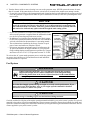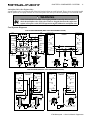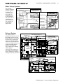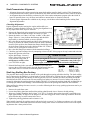
1
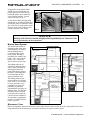
Port Engine Serial Number:
Stbd. Engine Serial Number:
Hull Identification Number:
Hull Identification Number
The Hull Identification Number (HIN) is located on the starboard side of the transom. Be sure to record the HIN (and
the engine serial numbers) in the space provided above. Please refer to the HIN for any correspondence or orders.
HIN
LOCATION
(TYPICAL)
© 2000 Bayliner Technical Publications. All rights reserved.
No part of this publication may be reproduced, stored in any retrieval system, or transmitted in any form by any means,
electronic, mechanical, photocopying, recording or otherwise, without prior written permission of Bayliner.
Printed in the United States of America.
General Notes
The material in this document is for information only and is subject to change without notice. While reasonable efforts have
been made in the preparation of this document to assure its accuracy, Bayliner assumes no liability resulting from errors or
omissions in this document, or from the use of information contained herein.
Due to our commitment to product improvement, Bayliner reserves the right to make changes in the product design,
specifications, and equipment at any time without notice or obligation. Illustrations and/or photos may show optional equipment.
All Bayliner products meet or exceed USCG (Unites States Coast Guard) and/or NMMA (National Marine Manufacturer’s
Association) construction standards. Manufactured with 1,1,1 Trichloroethane, a substance which harms public health and
environment during the manufacturing process by destroying ozone in the upper atmosphere.
Proprietary Rights
This document discloses subject matter in which Bayliner has proprietary rights. The information and design disclosed herein
were originated by and are the property of Bayliner. Neither receipt nor possession thereof confers or transfers any right to
reproduce, copy, alter or disclose the document or any part thereof, any information contained therein, or to construct boats or
any item from it, except by written permission from or written agreement with Bayliner. This document is to be returned upon
request to Bayliner.
TO BE THE BEST
For Total Customer Satisfaction
Congratulations and welcome aboard your new Bayliner Motoryacht!
Thank you for choosing our product. Bayliner is committed to the goal of
building the highest quality products in the marine industry and to providing the finest after-the-sale support in the world.
To keep our respected status as the number one boat builder in the world,
Bayliner has instituted an ongoing Total Customer Satisfaction Program.
The guiding principles of this program are:
✓
✓
✓
Design, build and support the finest marine products in the world,
in every market we serve.
Be personally and individually responsible for the customer’s total
satisfaction.
Remember that every customer has a choice, and we want them to
choose Bayliner!
Welcome to the Bayliner family. We are looking forward to serving your
boating needs, now and in the future!
CONTENTS
CHAPTER 1: ABOUT THIS MANUAL
1 Dealer Service
1 Boating Experience
1 Engine/Accessories Guidelines
1 Structural Limitations
1 Safety Standards
2 Qualified Maintenance
2 Hazard Warning Symbols
CHAPTER 2: PRODUCT DESCRIPTION
3 Layout View
3 Lifting Sling Positions
4 Hull Exterior Hardware
CHAPTER 3: COMPONENTS / SYSTEMS
5 VHF Radio
5 Depth Finder
5 Compass
5 Trim Tabs
5 Anchor Windlass (Option)
5 Spotlight (Option)
6 Electrical System
7 12-Volt DC System
7
7
7
7
7
8
8
Fuses and Circuit Breakers
Battery Switches
Batteries
Engine Alternators
Battery Charger
AC/DC Cabinet
110-Volt AC System
8
9
9
Shore Power
Inverter Power
Generator Power (Option)
10 Fuel System
11 Fuel System Diagrams
12 Fuel Management Board
12 Fuel Quality
12
13
13
14
Engine Room Ventilation System
Water Pickup Systems
Exhaust System
Shaft-Transmission Alignment
14 Checking Alignment
14 Shaft Log Stuffing Box Packing
15 Steering System
15 Rudder Stuffing Gland
15 Wash down System (option)
16 Fresh Water System
16 Water Heater
16 Drain System
17 Air Conditioning/Heating (Optional)
18 Bilge Pump System
18 Bilge Pump Maintenance
19 Marine Head System
19 Microwave Oven
20 Liquid Propane Gas Stove
20 LPG System Operation Summary
20 110-Volt AC/12-Volt Refrigerator
20 Audio/Video Equipment
CHAPTER 4: WIRING DIAGRAMS
21 Standard Dual Dockside
22 Accessory DC Circuits
23 Gas Engine Electrical System
24 Diesel Engine Electrical System
CHAPTER 5: ISO SYMBOLS
25 Definitions
LIMITED WARRANTY
27 What Is Not Covered
27 Other Limitations
27 Your Obligation
1
CHAPTER 1:
ABOUT THIS MANUAL
This Owner’s Manual Supplement was prepared to provide specific information about your yacht. Please study this
supplement and the Owner’s Manual carefully, paying particular attention to the LIMITED WARRANTY section.
Keep this supplement in a secure place and hand it over to the new owner when you sell the boat.
Dealer Service
Make certain that you receive a full explanation of all systems from the selling dealer before taking delivery of your
yacht. Your selling dealer is your key to service. If you experience any problems with your new yacht, immediately
contact the selling dealer. If for any reason your selling dealer is unable to help, you can call us direct on our customer service hotline: 360-435-8957 or send us a FAX: 360-403-4235
Boating Experience
If this is your first boat or if you are changing to a type of boat you are not familiar with, for your own comfort and
safety, please ensure that you obtain handling and operating experience before assuming command of the yacht.
We strongly recommend that you take one of the boating safety classes offered by the U.S. Power Squadrons
(http://www.usps.org/) or the U.S. Coast Guard Auxiliary (http://207.201.180.170/). For more course information,
including dates and locations of upcoming classes, visit their web sites or call their local offices.
Outside the U.S., your selling dealer, national sailing federation or local yacht club can advise you of local sea
schools or competent instructors.
!
WARNING
CONTROL HAZARD - A qualified operator must be in control of the yacht at all times. DO NOT
operate your yacht while under the influence of alcohol or drugs.
Engine/Accessories Guidelines
Your yacht’s engines and accessories were selected to provide optimum performance and service. Installing different
engines or other accessories may cause unwanted handling characteristics. Should you choose to install different
engines or to add accessories that will affect the boat’s running trim, have an experienced marine technician perform
a safety inspection and a handling test before operating your yacht by yourself again.
Structural Limitations
The command bridge, transom platform and bow platform are designed to be lightweight for proper boat balance.
The load limit for these platforms and the command bridge is 30 pounds per square foot, evenly distributed.
Safety Standards
Your yacht’s mechanical and electrical systems were designed to meet safety standards in effect at the time it was
built. Some of these standards were mandated by law. All of them were designed to insure your safety, and the safety
of other people, vessels and property.
Please read the Owner’s Manual for important safety standards and hazard information.
!
DANGER
DANGER
PERSONAL SAFETY HAZARD - DO NOT allow anyone to ride on parts of the
yacht not designated for such use. Sitting on seat backs, lounging on the forward
deck, bow riding, gunwale riding or occupying transom platform while underway is especially hazardous and will cause personal injury or death.
3788 Motoryacht • Owner’s Manual Supplement
2
CHAPTER 1: ABOUT THIS MANUAL
Qualified Maintenance
WARNING
!
To maintain the integrity and safety of your yacht, only qualified personnel should perform
maintenance on, or in any way modify: The steering system, propulsion system, engine control
system, fuel system, environmental control system, or electrical system.
Failure to maintain these systems (listed in the warning above) as designed could violate the laws in your jurisdiction
and could expose you and other people to the danger of bodily injury or accidental death. We recommend that you
follow the instructions provided in this supplement, the Owner’s Manual, the engine owner’s manual and the accessory instruction sheets included with your boat.
Hazard Warning Symbols
The hazard warning symbols shown below are used throughout this supplement to call attention to potentially dangerous situations which could lead to either personal injury or product damage. We urge you to read these warnings
carefully and follow all safety recommendations.
DANGER
!
This symbol alerts you to immediate hazards which WILL cause severe personal injury or
death if the warning is ignored.
WARNING
!
This symbol alerts you to hazards or unsafe practices which COULD result in severe personal
injury or death if the warning is ignored.
CAUTION
!
This symbol alerts you to hazards or unsafe practices which COULD result in minor personal
injury or cause product or property damage if the warning is ignored.
NOTICE
This symbol calls attention to installation, operation or maintenance information, which is
important to proper operation but is not hazard-related.
Fire and/or
Explosion Hazard!
Open Flame
Hazard
3788 Motoryacht • Owner’s Manual Supplement
Rotating Propeller
Hazard!
Personal Injury/
Falling Hazard
3
CHAPTER 2:
PRODUCT DESCRIPTION
Overall
Length
Bridge
Clearance
Beam
Draft
Fuel Tank
Capacity (gal)
Water Tank
Capacity (gal)
Holding Tank
Capacity (gal)
38’ 6”
14’ 0”
13’ 4”
3’ 6”
250
100
36
Layout View
STOVE
SINK
SINK
HEAD
BATHTUB
HANGING
LOCKER
GALLEY
MICROWAVE
OVER
REFRIG.
FORWARD
BERTH
ENGINE
ACCESS
ROPE
LOCKER
DINNETTE
TABLE
LOWER
HELM
GUEST
BERTH
HANGING
LOCKER
HANGING
LOCKER
Lifting Sling Positions
3788 Motoryacht • Owner’s Manual Supplement
4
CHAPTER 2: PRODUCT DESCRIPTION
Hull Exterior Hardware
LOCKER DRAIN
PORTLIGHTS
FUEL VENT FITTING
COCKPIT DRAINS
STARBOARD HULLSIDE
ANCHOR LOCKER
DRAIN - CLAMSHELL
OPTIONAL
A/C DISCHARGE
EXHAUST OUTLET
MACERATOR
DISCHARGE
GALLEY SINK
DRAIN
MARINE HEAD
HOLDING TANK VENT
WATER TANK
VENT
FUEL TANK
VENT
OPTIONAL
GEN. EXH.
PORT HULLSIDE
OPTIONAL
A /C DISCHARGE
MARINE HEAD
OVERBOARD
MULTI-PORT THRU HULL
FWD. & MID BILGE PUMPS
& SHOWER SUMP
COCKPIT / ENT. COCKPIT
DRAIN
CNTR. DRAIN
OPTIONAL
CITY WATER
INLET
TRANSOM
TRIM TAB
(TYPICAL)
STERN EYE
(TYPICAL)
3788 Motoryacht • Owner’s Manual Supplement
SACRIFICIAL
ANODE PLATE
RUDDER
(TYPICAL)
AFT
BILGE
PUMPS
5
CHAPTER 3:
COMPONENTS / SYSTEMS
VHF Radio
The VHF radio has a separate brochure, in your yacht’s owner’s packet, that explains its operating features. We
strongly suggest that you read the operating instructions before using the radio.
Depth Finder
The depth finder will provide you with measurements of water depth beneath the boat. We suggest that you read the
manufacturer’s operating instructions included in your yacht’s owner’s packet before using the unit.
! WARNING
DO NOT use the depth finder as a navigational aid to prevent collision, grounding, boat damage or
personal injury. When the boat is moving, submerged objects will not be seen until they are already
under the boat. Bottom depths may change too quickly to allow time for the boat operator to react.
If you suspect shallow water or submerged objects, operate the boat at very slow speeds.
Compass
Carefully read and follow the compass manufacturer’s calibration and operating instructions provided in your yacht’s
owner’s packet.
Trim Tabs
Trim tabs control the longitudinal and lateral trim of your boat at cruising speeds. Two
rocker switches identified by the words “BOW DOWN” are located at each helm station.
Once the best bow cruising trim is reached, use the port or starboard trim switches, one at
a time, to correct for unequal lateral loading. DO NOT use trim tabs to compensate for
excessive unequal weight distribution.
Trim tab adjustment should be performed by several short touches to the switch rather
than one long one. After each short touch allow about five seconds for the hull to react.
The trim tab hydraulic fluid reservoir is located in the engine compartment. The fluid
level should be checked periodically (at least once a year) and refilled as necessary.
TYPICAL
TRIM TAB
ROCKER
SWITCHES
TYPICAL
TRIM TAB
! WARNING
Improper use of trim tabs may cause loss of control. DO NOT use trim tabs in a following sea as
they may cause broaching or other unsafe handling characteristics. DO NOT let anyone unfamiliar with trim tabs to operate them.
Anchor Windlass (Option)
Please read the manufacturer’s instructions in your yacht’s owner’s packet. To
haul the anchor, use engine power (not the windlass) to move the boat to, and
directly over, the anchor. Activate the windlass to disengage the anchor from
the bottom by pulling it straight up. DO NOT pull the boat to the anchor using
the windlass or continue to operate the windlass if it stalls or is overloaded.
SPOTLIGHT
ANCHOR
WINDLASS
BOW PLATFORM
WINDLASS
CONTROLS
Spotlight (Option)
The spotlight has a separate brochure explaining its features. The spotlight
can be controlled from the upper helm.
3788 Motoryacht • Owner’s Manual Supplement
6
CHAPTER 3: COMPONENTS / SYSTEMS
Electrical System
We strongly recommend that you read and understand this section and the Electrical Section of the Owner’s Manual.
Wiring diagrams are provided in chapter 4 for use in troubleshooting electrical problems.
DANGER
!
•
•
•
•
•
EXTREME FIRE/EXPLOSION HAZARD!
To minimize the risks of fire and explosion, NEVER install knife switches or other arcing
devices in the fuel compartments.
NEVER substitute automotive parts for marine parts. Electrical, ignition and fuel system
parts were designed and manufactured to comply with rules and regulations that minimize
risks of fire and explosion.
DO NOT modify the electrical systems or relevant drawings.
Only qualified personnel should install batteries and/or perform electrical system maintenance.
Insure that all battery switches are in the OFF position before performing any work in the
engine spaces.
WARNING
!
FIRE/EXPLOSION HAZARD!
• Fuel fumes are heavier than air and will collect in the bilge areas where they can be accidently ignited. Visually and by smell (sniff test), check the engine and fuel compartments for
fumes or accumulation of fuel. Operate the bilge blowers for at least four minutes prior to
engine starting, electrical system maintenance or activation of electrical devices.
• Minimize the danger of fire and explosion by not exposing batteries to open flame or sparks.
It is also important that no one smoke anywhere near the batteries.
CAUTION
!
SHOCK/ELECTRICAL SYSTEM DAMAGE HAZARD!
• Never disconnect the battery cables while the engine is running as this can cause damage to
your boat’s electrical system components.
• The battery charging systems (alternators and battery charger) on your yacht are designed
to charge conventional lead-acid batteries. Before installing gel-cell or other new technology
batteries, consult with the battery manufacturer about charging system requirements.
NOTICE
• Electrical connections are prone to corrosion. To reduce corrosion caused electrical problems, keep all electrical connections clean and protect them with a spray-on protectant such
as Corrosion Guard®.
• VOLTAGES - All boats use either 110-volt AC/60 Hertz, 240-volt AC/60 Hertz or 220-volt
AC/50 Hertz single phase systems, and 12-volt DC or 24-volt DC. Electrical distribution
panels are labeled with voltage and frequency of AC and DC.
3788 Motoryacht • Owner’s Manual Supplement
CHAPTER 3: COMPONENTS / SYSTEMS
7
12-Volt DC System
Fuses and Circuit Breakers
Fuses and circuit breakers for main accessory power, float switches and windlass power are located in the AC/DC
cabinet (port side of salon). Electronic’s power is provided at the upper helm station. Some equipment, such as depth
finders and shower pumps may have secondary fuse protection at the unit.
Battery Switches
A separate rotary battery switch is provided for each battery. In addition, a parallel switch is provided at each helm to enable you to start
the engines using all engine batteries in the event that engine battery
power is low.
Batteries
The batteries supply electricity for lights, engine and generator starting, as well as power to turn on accessories. Periodically remove the
battery caps and check the electrolyte level. If the zinc plates are
exposed, add distilled water until they are covered. Corroded battery
terminals can be cleaned with baking soda and water. After cleaning
the terminals, coat them with a light film of grease. Be sure all battery
connections are tight.
Battery condition can be checked on the “Electrical System Monitor”
located on the DC distribution panel. The condition of the accessory
battery can be read on the starboard engine voltmeter when the accessory battery switch is in the ON position. The starboard voltmeter will
register the accessory battery state even when the engines are shut
down and the ignition switches are turned off.
INVERTER
SWITCH
BATTERY
SWITCHES
THE BATTERY SWITCHES AND THE INVERTER
SWITCH ARE LOCATED ON THE STARBOARD
SIDE OF THE COCKPIT
Engine Alternators
The engine alternators will maintain proper charge levels in the engine and accessory batteries (some situations may
require running engines at 1200 RPM to initiate charging).
Battery Charger
In addition to the engine alternators, your yacht is equipped with a battery charger. We recommend that you thoroughly read and understand the battery charger manual, provided in your yacht’s owner’s packet, before using the
charger. The battery charger is located in the utility room.
!
CAUTION
The battery charging systems (alternator and battery charger) installed are designed to charge
conventional lead-acid batteries. Before installing gel-cell or other new technology batteries,
consult with the battery manufacturer about charging systems requirements.
3788 Motoryacht • Owner’s Manual Supplement
8
CHAPTER 3: COMPONENTS / SYSTEMS
AC/DC Cabinet
GENERATOR
INSTRUMENTS
(OPTION)
WATER LEVEL
INDICATOR
INVERTER
CONTROL
PANEL
WINDLASS
POWER
(OPTION)
110-VOLT AC
VOLTMETER
VOLTMETER
SELECTOR
12-VOLT
DC PANEL
GENERATOR
START/STOP
SWITCH
DC MASTER
CIRCUIT
BREAKER
POLARITY
LIGHTS
MASTER
CIRCUIT
BREAKERS
12-VOLT DC
VOLTAGE
GAUGE
LINE
MASTER
BREAKERS
COMPONENT
BREAKERS
MACERATOR
SWITCHES
110-VOLT
AC PANEL
110-Volt AC System
The AC system can be energized by shore power, inverter power, or the optional onboard generator. Master Circuit
breakers, located on the AC panel (see photo above), provide power source selection. This system is designed so that
ship’s power and shore power sources cannot supply power simultaneously.
!
CAUTION
Whether using shore power, inverter power or the optional generator, the simultaneous use of
several AC components can result in an overloaded circuit. It may be necessary to turn off one
or more accessories in order to use another accessory.
!
CAUTION
WATER HEATER DAMAGE HAZARD! Do not energize the water heater electrical circuit
until the heater is COMPLETELY filled with water. Even momentary operation in a dry tank
will damage the heating elements. Warranty replacements WILL NOT be made on elements or
tank damaged in this manner.
Shore Power
Shore power receptacle(s) are located outside the cabin on the port side. Shore power receptacles are rated either 30
or 50 amps with appropriate power cords furnished. Since not every shore installation has 30 amp service, we recommend that 15 and 20 amp adapters be purchased. However, whenever 15 or 20 amp adapters are used, there will be a
corresponding drop in supplied power from the dockside system.
!
DANGER
FIRE/EXPLOSION/SHOCK HAZARD!
• To minimize shock and fire hazard, DO NOT modify electrical systems or relevant drawings.
• DO NOT alter shore power connectors and use only compatible connectors.
• Only qualified personnel should install batteries and/or perform electrical system maintenance.
3788 Motoryacht • Owner’s Manual Supplement
CHAPTER 3: COMPONENTS / SYSTEMS
!
9
CAUTION
SHOCK/ELECTRICAL SYSTEM DAMAGE HAZARD!
• Never connect dockside power to your boat outside North America unless you have purchased the International electrical conversion option, which is rated for 220-volt/50 Hertz.
North American systems are rated for 110-volt/60 Hertz power.
• Use double insulated or three-wire protected electrical appliances when possible.
NOTICE
• When using shore power, the simultaneous operation of several AC accessories can result in
an overloaded circuit. It may be necessary to turn off one accessory while operating another.
Before connecting to shore power, ensure all breakers and switches on the AC master panel are in the OFF position.
always attach the shore power cord to the boat inlet first; then to the dockside connection to prevent shock or injury
from an accidental dropping of the “hot” cord into the water.
!
WARNING
SHOCK/ELECTRICAL SYSTEM
DAMAGE HAZARD!
Monitor the electrical control panel’s polarity indicators when connecting shore power to your
boat. A GREEN light illuminating after the power cord is plugged into the boat’s external
power receptacle indicates acceptable electrical power in which you may energize the main
breaker switches. A RED light, however, indicates reversed polarity, which could cause electrical system damage and possibly electrical shock injuries. In this case, DO NOT energize the
main breaker switches. Instead, immediately disconnect the shore power cord (always from the
dockside outlet first) and notify marina management.
Check for proper polarity as outlined in the warning above. Each dockside inlet is labeled above the weatherproof
cover, line 1 or line 2, which corresponds to the line each operates on the AC master panel. This system is designed
so that each line operates independent of the other. Activate the AC system by first turning on the master breakers,
then each individual component as required. Voltage on each line can be read by setting the voltmeter selector switch.
Inverter Power
The inverter operation manual, in your yacht’s owner’s packet, describes inverter operating procedures in detail. We
strongly recommend that you thoroughly read and understand the inverter manual before using the inverter. The
inverter is located in the utility room, under the mid berth.
Activate the AC system under inverter power by switching ON the inverter master breaker (located on the starboard
side of the cockpit) and pressing the on/off switch on the inverter control panel (located above the AC master panel in
the AC/DC cabinet). The inverter provides AC power to receptacles and the microwave oven only.
Generator Power (Option)
Your yacht may come equipped with a generator. Prior to initially operating your generator we strongly urge you to
read the manufacturer’s operating instructions included in the owner’s packet. Always observe the following:
• Follow instructions in the generator manual for pre-start checks and break-in procedures.
• The starter switch is on the AC electrical panel (located on the port side of salon).
1. Open the generator seawater intake valve before starting the generator. The seawater intake valve must remain
open during generator operation, and the seawater strainer should be checked frequently for leaks and/or debris.
2. Operate the bilge blowers for a minimum of four minutes before starting the generator. Leave the blowers on
while the generator is operating unless the yacht is running at cruising speed.
3. Diesel generator; turn the pre-heat switch to the ON position and allow one minute for pre-heating.
Gas generator; simultaneously press the oil pressure button and turn the starter switch until the generator starts.
3788 Motoryacht • Owner’s Manual Supplement
10
CHAPTER 3: COMPONENTS / SYSTEMS
4. Turn the Starter switch to start, releasing it as soon as the generator starts. NEVER operate the starter for more
than 30 seconds. If the generator does not start, wait at least 30 seconds before another start attempt is made.
• If your fuel system features a fuel management board (located on the forward bulkhead in the engine room) fuel
to run the generator is supplied from either the port or starboard fuel tanks (see the fuel system diagrams in the
next section).
NOTICE
Environmental Hazard - If your boat features a diesel fuel system and a fuel management
board; the generator fuel selector valves MUST be set so that return fuel is routed back to the
same tank from which it was drawn. Otherwise, generator fuel drawn from a partially full tank
and returned to a full tank may spill overboard through the tank venting system.
• If your fuel system does not feature a fuel management board,
fuel to run the generator is supplied from the starboard fuel tank
(see the fuel system diagrams in the next section).
• In addition to servicing the filters attached to the diesel generator, the filter/separator located near the fuel line valves should be
serviced as described in the manufacturer’s operating manual.
• The coolant mixture installed at the factory consists of equal
parts of water and antifreeze (Ethylene Glycol).
• Oil pressure and water temperature gauges are adjacent to the
AC panel and monitor the engine functions of your generator.
Gauge readings during normal generator operation are: Temperature between 165° to 195° F; Oil pressure between 35-55 PSI.
To activate the AC system under generator power; switch the generator master circuit breakers to ON and then turn on each individual
component breaker as required.
Fuel System
!
WARNING
FIRE/EXPLOSION HAZARD - It is very important that the fuel system be
inspected thoroughly the first time it is filled and at each subsequent filling.
The Fueling Instructions in the Owner’s Manual and the Fuel Recommendations
in the engine operation manual must be followed.
!
CAUTION
Air in the diesel supply system can stop an engine or severely restrict performance. If you
suspect air in your diesel fuel lines, refer to your engine operation manual for detailed
instructions on how to “bleed” the system.
!
CAUTION
Avoid the storage or handling of gear near the fuel lines, fittings and tank.
Carefully read the Fuel Section of the engine operation manual included in your yacht’s owner’s packet. Give special
attention to the subject of Fuel Recommendations. Filters/separators should be inspected periodically for debris and
replaced as needed according to the instructions detailed in your engine manual, generator manual and in the filter literature supplied in your yacht’s owner’s packet.
3788 Motoryacht • Owner’s Manual Supplement
CHAPTER 3: COMPONENTS / SYSTEMS
11
Anti-siphon Valve (Gas Engines Only)
An anti-siphon valve is an integral part of the fuel line barb fitting on each fuel tank. These valves are spring loaded
and are opened by fuel pump vacuum. If a fuel line ruptures the valve prevents the siphoning of fuel from the tank.
WARNING
!
FIRE/EXPLOSION HAZARD - If an engine problem is caused by fuel starvation,
check the anti-siphon valve. If the valve is stuck or clogged, shut down the engine and
replace it. Except in a crisis, NEVER operate the engines without the anti-siphon valve.
Fuel System Diagrams
FUEL SYSTEM DIAGRAMS (WITH FUEL MANAGEMENT BOARD)
PORT
FUEL TANK
STBD
FUEL TANK
PORT FUEL TANK
STBD FUEL TANK
GAS
ENGINES
VENT
RETURN
RETURN
RETURN
RETURN
RETURN
RETURN
VENT
SENDER
SENDER
SENDER
SENDER
PICKUP
PICKUP
PICKUP
PICKUP
PICKUP
PICKUP
VENT
PORT PICKUP
PORT PICKUP
STBD PICKUP
STBD PICKUP
GEN PICKUP
GEN PICKUP
FUEL FILL
VENT
FUEL FILL
FUEL FILL
FUEL FILL
FILTER
PORT
ENG
STBD
ENG
STBD
ENG
PORT
ENG
GEN
GEN
FUEL
FILTER
FUEL SYSTEMS (WITHOUT FUEL MANAGEMENT BOARD)
DIESEL ENGINE
FUEL SYSTEM
DIAGRAM
VENT
PORT
FUEL TANK
VENT
VENT
STBD
FUEL TANK
PORT
FUEL TANK
GAS ENGINE
FUEL SYSTEM
DIAGRAM
GENERATOR RETURN
PORT ENG. RETURN
STBD ENG. RETURN
SENDER
SENDER
STBD ENG. PICKUP
FUEL FILL
FUEL FILL
FUEL SHUTOFF VALVE
STBD
FUEL TANK
GENERATOR RETURN
PORT ENG. RETURN
STBD ENG. RETURN
SENDER
SENDER
GENERATOR PICKUP
PORT ENG. PICKUP
VENT
GENERATOR PICKUP
PORT ENG. PICKUP
STBD ENG. PICKUP
FUEL FILL
FUEL FILL
FUEL SHUTOFF VALVE
FUEL
FILTER
FUEL
FILTER
PORT
ENG
PORT
ENG
STBD
ENG
STBD
ENG
GEN
FUEL
FILTER
FUEL
SHUTOFF
VALVE
FUEL SHUTOFF VALVE,
TYPICAL (3 - PLACES)
GEN
FUEL
FILTER
3788 Motoryacht • Owner’s Manual Supplement
12
CHAPTER 3: COMPONENTS / SYSTEMS
Fuel Management Board
Your yacht may or may not be equipped with a fuel management board.
• On models equipped with a fuel management board,
fuel can be directed from either tank to the engines and
generator using the supply valves. The fuel management board is located under the steps next to the galley.
• On models that are not equipped with a fuel management board, the port fuel tank provides fuel for the port
engine while the starboard fuel tank provides fuel for
the starboard engine and the generator.
TYPICAL FUEL MANAGEMENT BOARD
Fuel Quality
Make sure your fuel suppliers are reputable and can be
relied upon to furnish clean, high quality fuel. Once you
have found such suppliers, keep your tank as full as possible with their fuel, allowing for expansion due to temperature variations. Then, if you are forced to add to the tank
NOTE: FUEL MANAGEMENT BOARDS WILL
VARY DEPENDING ON ENGINE TYPE
with a potentially poor quality supply, the portion of poor
AND OPTIONAL EQUIPMENT
quality fuel will be minimized.
Fuel Fills and Vents
Fuel fills are located either on the aft deck or on the side decks adjacent to the aft cockpit. Fuel receptacle caps are
marked “Diesel” or “GAS”. Fuel vents are normally located in the hull or transom below and in the same general area
as the fill. If you experience difficulty filling the fuel tank, check to see that the fuel fill and vent lines are free of
obstructions and kinks.
Engine Room Ventilation System
BLOWERS
The bilge blower removes fumes from the
engine compartment and draws fresh air into
the compartment through the deck vents. To
ensure fresh air circulation, operate the bilge
blowers for at least four minutes before starting
the engines or generator, during starting, and
while operating the yacht below cruising speed.
VENTILATION
HOSES
ROUND
COLLECTORS
WARNING
STBD
HULLSIDE
Operation of the
blower system is NOT
A GUARANTEE that
explosive fumes have
been removed. If you smell any fuel,
DO NOT start the engine. If the
engine is already running, immediately shut off the engine and all electrical accessories. Investigate
immediately. DO NOT obstruct or
modify the ventilation system.
DIESEL ENG’S:
HOSES ROUTE AT
TOP OF BULKHEAD
GAS ENG’S:
HOSES ROUTE AT
BOTTOM OF BULKHEAD
!
3788 Motoryacht • Owner’s Manual Supplement
FWD
CHAPTER 3: COMPONENTS / SYSTEMS
13
Water Pickup Systems
The seawater
strainers should be
checked regularly
for debris. The
standard layout is
one strainer for
each engine, one
for the generator
and one for the air
conditioning system (if installed).
The strainers are
located in the
engine room.
ENGINE
WATER PICKUP
(TYPICAL GAS & DIESEL)
GENERATOR
WATER PICKUP
(TYPICAL GAS & DIESEL)
Exhaust System
DIESEL ENGINE EXHAUST SYSTEM
45° ELBOW, TYP.
6" DIA. EXHAUST HOSE, TYP.
GENERATOR
EXHAUST SYSTEM
(TYPICAL GAS & DIESEL)
90°
ELBOW
THRU-HULL
LSID
POR T HUL
E
2" DIA.
EXH. HOSE
GENERATOR
MUFFLER
PORT
MUFFLER
RISER
TYP.
STBD
MUFFLER
TRANSOM
The exhaust system is
designed to keep water out of
the engines in most sea conditions. However, care should
be taken NOT to anchor the
stern to sea, and the engines
should NOT be shut off if the
seas are too high. Always use
good seamanship and consider the sea conditions
before anchoring or shutting
off the engines.
Check all of the exhaust system clamps after the first 20
hours. Continue to check the
clamps periodically after that.
GENERATOR
45° EXH.
PORT, TYP.
GAS ENGINE EXHAUST SYSTEM (PORT SIDE SHOWN, STBD SIDE TYPICAL)
45° EXH.
PORT, TYP.
5" DIA. EXHAUST HOSE
TEE FITTING
4" DIA.
EXHAUST HOSE
45° ELBOW
MUFFLER
90° ELBOW
3788 Motoryacht • Owner’s Manual Supplement
14
CHAPTER 3: COMPONENTS / SYSTEMS
Shaft-Transmission Alignment
• Alignment between the engine transmission output shaft and the propeller shaft is critical. This alignment has
been performed at the factory, and was rechecked by the dealer after the boat had been in the water for 48 hours.
• An alignment inspection should be performed as part of the routine maintenance program (after the initial 30
hours of operation, then every 60 hours) and whenever unusual noise or vibration is noticed.
• To insure proper alignment after a hallout or dry storage, wait 48 hours after launching before making final
alignment adjustments.
Checking Alignment
Engine alignment requires moving the engine and should be performed by a marine mechanic. However, checking the alignment is relatively simple when these steps are followed:
1. Remove the flange bolts at the transmission-to-prop shaft coupling
and slide the shaft aft until the flanges are about 1/4" apart.
2. Rotate the shaft to see if there is obvious “wobble” of the shaft
flange. If there is, it may indicate shaft damage and should be
inspected by a marine mechanic as soon as possible.
3. Move the shaft up and down and from side to side to determine, as
closely as possible, the central position where the shaft is normally TYPICAL TRANSMISSION-TO-PROP SHAFT COMPONENTS
located. At this position, the transmission flange should align with
NOTE: TRANSMISSION-TO-PROP SHAFT COMPONENTS
VARY DEPENDING ON ENGINE TYPE AND SIZE.
the shaft flange without moving the shaft more than 1/8". If this is
not the case, a misalignment condition exists.
4. Move the shaft flange into contact with the transmission flange.
5. Check the gap between flange faces by attempting to insert a 0.003" feeler gauge at the top, bottom and each side.
6. Repeat this operation after rotating the shaft flange 1/4 turn (3
! CAUTION
times). If the feeler gauge can be
If a shaft misalignment exists, have a qualified marine mechanic pereasily inserted at any point, a
form an alignment as soon as possible. Continued use may lead to premisalignment condition exists
mature engine, transmission, shaft, shaft seal and/or hull damage.
(see CAUTION on right).
7. Reinstall the flange bolts, nuts and lock washers (if provided) and
torque to the specifications listed to the right. Replacement bolts, nuts
and washers must be corrosion resistant and grade 8 or better.
Shaft Log Stuffing Box Packing
BOLT SIZE
3/8" - 24 - 7/16" - 20 1/2" - 20 - 5/8" - 18 - M16 x 1.5 -
-
-
-
-
TORQUE
40 lbs. (+/- 7 lbs.)
65 lbs. (+/- 10 lbs.)
95 lbs. (+/- 15 lbs.)
200 lbs. (+/- 30 lbs.)
175 lbs. (+/- 25 lbs.)
The propeller shaft emerges from the bottom of the yacht through an opening called the shaft log. The shaft stuffing
box is connected to the shaft log by a short length of special flexible hose. Packing rings are compressed around the
shaft by the packing gland. The stuffing for the box prevents excessive amounts of water from leaking around the
shaft and into the boat. Normal wear can cause stuffing box leakage to increase. Excessive leakage can usually be
stopped by tightening the packing gland nuts slightly. DO NOT over tighten the packing gland nuts. A slight leak (up
to 10 drops per minute while running) is normal and helps lubricate the packing and is therefore NECESSARY.
When stuffing box leakage becomes excessive, even after following the above steps, packing replacement can be performed as follows;
1. Remove the yacht from water.
2. Loosen the packing gland nuts and back the packing gland from the sleeve. Remove the old packing.
3. Wrap new packing around the shaft (4 rings, 3/16" for 1 1/2" shafts), then cut the rings with a razor blade at an
angle approximately 30 degrees to the long axis of the shaft. Stagger the ends of each ring around the shaft and
insure that the ring are at the bottom in the sleeve.
4. Tighten the packing gland nuts until resistance is felt.
When initially launched, the packing must be allowed to leak at a rate of 5 to 30 drops per minute, as it will expand
and seal from water contact and friction heat from the turning shaft. Failure to allow this leak-off will result in packing burnout after a short period of time.
3788 Motoryacht • Owner’s Manual Supplement
CHAPTER 3: COMPONENTS / SYSTEMS
15
Steering System
Your yacht’s steering system is
manual hydraulic, not power steering. At no time should you expect
this system to turn as easily as a
car’s power steering.
A rhythmic pulsing when turning
the wheel is a characteristic of the
pump and is not a malfunction.
Also, when coming off a hard-over
position, resistances may be felt,
followed by a distinct sound. This is
a normal situation resulting from the
release of the check valve.
The fluid reservoir for the hydraulic
steering system is located in the aft
end of the engine compartment. Follow instructions in your yacht’s
owner’s packet and on the reservoir.
Check the fluid level and pressure
regularity.
M
NSO
TRA
Rudder Stuffing Gland
The rudder stuffing gland is part of the assembly where the rudders emerge from the bottom of the boat. It is very
similar to the propeller shaft stuffing box and will require the same maintenance. Since it does not receive the same
wear as the propeller shaft, repacking is seldom required. This shaft stuffing gland should not leak any water.
Wash down System (option)
The outlet for the raw
water (seawater) wash
down system is located
on the port side of the
cockpit. The seacock and
pump for the wash down
system can be accessed
through the port cockpit
floor hatch. Open the
seacock before turning
the system on.
3788 Motoryacht • Owner’s Manual Supplement
16
CHAPTER 3: COMPONENTS / SYSTEMS
Fresh Water System
The water filter, located in
the accessory room outboard
of the aft stateroom, should
be inspected and cleaned
often.
When connected to a dockside water supply, the DC
power switch for the water
pump should be turned OFF.
The water tank is equipped
with a water level indicator
in the AC/DC cabinet on the
starboard side of the salon. It
is always a good idea to top
off the water tank at every
opportunity to avoid the possibility of running short of
fresh water.
The water fill is located on
the starboard side of the
deck and the water tank is
located under the bed in the
aft berth.
When your boat is to be left
unattended for long periods
of time, pump the water tank
dry to prevent stored water
from becoming stagnant and
distasteful. Should it
become necessary to disinfect the fresh water system,
ask your dealer about treatment systems available and
follow the manufacturer’s
instructions.
WATER
PUMP
ENTERTAINMENT
CENTER
GALLEY
HOT WATER
TANK
TO HEAD
WATER
TANK
TRANSOM
SHOWER
CITY
WATER
WATER SYSTEM DIAGRAM
(INCLUDING OPTIONS)
Water Heater
!
WARNING
SCALDING HAZARD! Water heated by the heat exchanger system can reach temperatures
high enough to scald the skin. Use care when using hot water after running the port engine for
any period of time.
COMPONENT DAMAGE HAZARD! Water heaters must be kept full of water to avoid damage
to the 110-volt heating elements. They should also be drained (power turned OFF) when the
possibility of freezing exists.
Please read the manufacturer’s instructions supplied in your yacht’s owner’s packet. The water heater is connected to
the AC power system. It is located on the starboard side of the accessory room, outboard of the aft stateroom, forward
of the engine.
Drain System
The sinks and showers (“gray water”) drain overboard. The sinks are above the water line and have gravity drains
while the shower is pump-drained. The shower drain sump pump is located under the stairs, next to the galley. This
sump pump automatically shuts off after the shower is drained.
3788 Motoryacht • Owner’s Manual Supplement
CHAPTER 3: COMPONENTS / SYSTEMS
17
Air Conditioning/Heating (Optional)
Your yacht may be equipped with an optional air conditioning system. Both heating and cooling are controlled from
the same panel. Please refer to the manufacturer’s operating instructions included in your yacht’s owner’s packet.
AIR CONDITIONING
WATER PICKUP SYSTEM
FWD A/C
SYSTEM
AFT A/C
SYSTEM
3788 Motoryacht • Owner’s Manual Supplement
18
CHAPTER 3: COMPONENTS / SYSTEMS
Bilge Pump System
MID BILGE
PUMP SYSTEM
TRANSOM
Your yacht is equipped with six
impeller-type bilge pumps. The
bilge pumps are controlled by automatic bilge pump switches (autofloat switches) and/or switches on
the dash panel.
The autofloat switches activate
whenever water accumulates above
a preset level in the bilge. They are
wired directly to the battery and
will normally function even when
the yacht is completely shut down
and unattended, such as when the
yacht is moored at a marina.
AFT BILGE
PUMP SYSTEM
Bilge Pump Maintenance
Bilge pumps should be checked
often to verify that they are working
properly. To check a bilge pump’s
operation, activate the dashmounted switch. Verify that water
in the bilge is pumped overboard. If
bilge water is present and the pump
motor is running but not pumping,
inspect the discharge hose for a
kink or collapsed area. If no problems are found, check the bilge
pump housing for clogging debris:
FWD BILGE
PUMP SYSTEM
To remove the power cartridge:
1. Lift the tab while rotating the fins counter-clockwise and lift
out the power cartridge (Fig. 1).
2. Clear the housing of debris.
TAB
FIN
FIG. 1
To reinstall the power cartridge:
1. Make sure the “O” ring is properly seated and coat
the “O” ring with a light film of vegetable oil or
mineral oil (Fig. 2).
2. Align the two cams on either side of the power cartridge with the two slots on the outer housing. Press
the power cartridge into the housing and twist clockwise. Ensure proper reinstallation by attempting to
twist the fins counter-clockwise without lifting the
tab. The cartridge should stay in place.
3788 Motoryacht • Owner’s Manual Supplement
LIGHT FILM OF OIL
OUTER HOUSING
POWER CARTRIDGE
“O” RING
FIG. 2
CHAPTER 3: COMPONENTS / SYSTEMS
If applicable, the autofloat switch
should also be checked often for
proper operation. Lift the float by
turning the plastic insert where the
wires enter the housing, 1/4 turn
counter-clockwise (Fig. 3).
As the float is lifted, the bilge pump
should turn on. If lifting the float does
not turn the pump on, check the inline
fuse. If the fuse is good but the switch
does not work, it may indicate a bad
switch or possibly a low battery.
19
TYPICAL FLOAT SWITCH
FLOAT
FLOAT
DETAIL
PLASTIC
INSERT
FIG. 3
ON POSITION (UP)
OFF POSITION (DOWN)
NOTICE
Discharge of oil, oil waste or fuel into navigable waters is prohibited by law. Violators are subject to legal action by the local authorities.
Marine Head System
The marine head system is
designed so that waste from
either head may be flushed
into the holding tank or
overboard (where regulations permit). Routing is
decided by the setting of the
head y-valve. Access to the
head y-valve is under the
floor at the foot of the steps.
WATER PICKUP SYSTEM
The holding tank can be
emptied by dockside pumpout or, where permitted, by
actuating the macerator
pump from the DC panel in
the salon. The holding tank
is located under the mid
stateroom and the steps.
The holding tank on your
motoryacht has a level indicator. Even so, it is advisable
to empty the tank at every
opportunity to reduce the
possibility of problems
which might be caused by an
indicator error. The dockside
discharge fitting is located
on the port side of the deck.
Check with local authorities
for regulations regarding the
legal use of marine head systems in your area.
Microwave Oven
Before attempting to operate the microwave oven, make sure the breaker switch on the AC master panel is ON. Operating instructions for the microwave oven can be found in your yacht’s owner’s packet.
3788 Motoryacht • Owner’s Manual Supplement
20
CHAPTER 3: COMPONENTS / SYSTEMS
Liquid Propane Gas Stove
Your yacht may come equipped with a liquid propane gas (LPG) three-burner stove/oven. Before attempting to operate the LPG stove/oven, read the operating instructions included in your yacht’s owner’s packet.
DANGER
!
EXTREME FIRE/EXPLOSION HAZARD - LPG is heavier than air, and if allowed to
settle, accumulate, and if ignited, WILL CAUSE AN EXPLOSION!
WARNING
!
FIRE/PERSONAL INJURY HAZARD - Areas near burners and grates may become hot
enough to cause burns. DO NOT touch burners, grates or areas near units as they may
be hot, even when they are dark in color. During and after use, do not touch or let clothing or other flammable material come in contact with units or areas near units (burner tops,
main frame sides and back, searails and pot holders) until they have had sufficient time to cool.
Always have an approved ABC-type fire extinguisher in galley area.
LPG System Operation Summary
• Close the tank valve immediately in any emergency.
(LPG tank is located under upper station dash)
• Be sure all appliance valves are closed before opening
the tank valve.
• Always apply a lit match or other flame source to burner
before opening burner valve.
• Close the tank valve whenever appliance is not in use.
• Test the system for leakage at least twice a month in
accordance with the following procedure:
1. With appliance valves CLOSED and with tank valve
OPEN, note the pressure on gauge.
2. CLOSE the cylinder valve. If the pressure reading on the
gauge drops, THERE IS A LEAK IN THE SYSTEM!
3. Locate the leak by applying liquid detergent or soap and
water solution to all connections.
4. NEVER use flame to check for leaks!
5. After the leak has been repaired, re-check the system
before using appliances.
LPG
REGULATOR
APPLIANCE
FUEL HOSE
CONNECTION
REGULATION SYSTEM
CONNECTING FITTING
PRESSURE
GAUGE
TANK VALVE
HANDLE
RELIEF
VALVE
ASME LPG
FUEL TANK
TYPICAL LPG TANK COMPONENTS
110-Volt AC/12-Volt Refrigerator
Your yacht may feature a 110-volt AC/12-volt DC refrigerator. Please refer to the manufacturer’s instructions supplied in your yacht’s owner’s packet. The refrigerator operates on 12-volt DC power unless the 110-volt AC system is
hooked up to shore power and the AC refrigerator breaker is ON.
NOTICE
In less than 24 hours, the refrigerator can render a 100-amp battery useless for engine starting.
When operating on 12-volts, it is advised that the cold setting not be set higher than two (2). It
is also advisable to turn off your refrigerator at night or when not in use. If you are going out
for more than a day and cannot connect to dockside power, plan to run the engine each day to
maintain a charged battery.
Audio/Video Equipment
The standard and optional audio/video equipment on your yacht have separate brochures explaining their operating
features. Note that AM radio reception may be impaired anytime the engine is running.
3788 Motoryacht • Owner’s Manual Supplement
21
CHAPTER 4:
WIRING DIAGRAMS
Standard Dual Dockside
3788 Motoryacht • Owner’s Manual Supplement
22
CHAPTER 4: WIRING DIAGRAMS
Accessory DC Circuits
3788 Motoryacht • Owner’s Manual Supplement
CHAPTER 4: WIRING DIAGRAMS
23
Gas Engine Electrical System
3788 Motoryacht • Owner’s Manual Supplement
24
CHAPTER 4: WIRING DIAGRAMS
Diesel Engine Electrical System
3788 Motoryacht • Owner’s Manual Supplement
25
CHAPTER 5:
ISO SYMBOLS
These ISO symbols may be used throughout your boat, the Owner’s Manual and this Owner’s Manual Supplement to
identify and describe various systems and components.
Definitions
Symbol
Description
Symbol
Description
Symbol
Description
Air Cooled Charge
Air Cooler
Air, General
Air, Intake
(For Combustion)
Anchor
Blower
Compass
Counter Clockwise
Rotation
Crankshaft Power
Disengage
Elapsed Time
Electric Generator
Electrical Preheat for
Diesel Engine
Engage
Engine
Engine Air Intake
Engine Coolant
Engine Exhaust Gas
Engine Exhaust
Gas Pressure
Engine Exhaust Gas
Temperature
Engine Inlet Air Filter
Engine Inlet Air Pressure
Engine Inlet Air
Temperature
Engine Oil
Engine Oil Filter
Engine Oil Level
Engine Oil Pressure
Engine Oil Temperature
Engine Rotation Speed,
R/MIN
Engine Start
Engine Water Jacket
Drain
Exhaust Gas
Filter
Fresh Water
Fresh Water Cooled
Charged Air
Fresh Water Tank
Fuel, Diesel
Fuel Filter
Fuel General
Fuel Level
Fuel, Liquid Propane
Gas
Fuel Shut Off
Fuel Tank, Diesel
Fuel Tank, LPG
Fuel Tank, Unleaded
Fuel, Unleaded
3788 Motoryacht • Owner’s Manual Supplement
26
CHAPTER 5: ISO SYMBOLS
Symbol
Description
Symbol
Description
Symbol
Description
Heat Exchanger
Holding Tank
Horn
Hydraulic Oil
Hydraulic Oil Filter
Hydraulic Oil Level
Hydraulic Oil Pressure
Hydraulic Oil
Temperature
Hydraulic System
Hydraulic System
Malfunction
Interior Light
Lift Point
Light
Lubricating Oil
Malfunction
No Open Flame
Oil Tank
Outboard Drive
Outboard Drive Tilt
Pressure
Propeller
Propshaft Power
Propulsion System Trim
Propulsion System
Trim,
Bow Down
Propulsion System
Trim,
Bow Up
Pump
Read Owner’s Manual
Seawater
Shift Only Fwd-N-Rev
Sling Location
Tank
Throttle/Shift
Transmission
Transmission Oil
Transmission Oil Filter
Transmission Oil Level
Transmission Oil
Malfunction
Transmission Oil
Pressure
Transmission Oil
Temperature
Trim Tab Operation
Trim Tab Operation,
Bow Down
Trim Tab Operation,
Bow Up
Volume Empty
Volume Full
Volume Half Full
Warning
Warning Electrical
Hazard
Warning Fire Risk
Warning Hot
Waste Water, Sewage
Water Flushing
Connector
Windshield Washer
Tank
Windshield Wiper
& Washer
3788 Motoryacht • Owner’s Manual Supplement
27
EXPRESS LIMITED WARRANTY
BAYLINER MARINE CORPORATION, EXPRESS LIMITED WARRANTY
Limited Warranty for New 2000 or 2001 Model Year Motoryachts
(3388, 3788, 3988, 4087, 4788, 5288 and 5788)
Bayliner warrants to the first retail purchaser (“Owner”) of a new 2000 or 2001 Model Year Bayliner Motoryacht (3388, 3788, 3988, 4087, 4788, 5288 and 5788)
purchased from an authorized dealer, operated under normal, noncommercial use, that the selling dealer will (or, in Bayliner’s discretion, it will):
(1) repair or replace any parts found to be defective in materials and workmanship occurring within 1 (one) year of the date of delivery;
(2) repair any defects in materials and workmanship in structural fiberglass parts of the hull (and specifically excluding the deck) occurring within
7 (seven) years of the date of delivery; and
(3) repair any defects in materials and workmanship that result in osmotic blistering of the exterior gel coat surface of the hull laminate occurring
within 5 (five) years of the date of delivery, except that Bayliner shall not be liable or responsible to correct, repair, or replace any damage from
osmotic blistering if the original gel surface has been altered in any way, including repair or application of any coating other than marine antifouling bottom paint or improper surface preparation for paint, or excessive sanding or sandblasting. Bayliner shall repair osmotic blisters based
upon customary and reasonable charges with the method and extent of repair subject to Bayliner’s prior approval.
Owner’s sole and exclusive remedy for defects covered by this limited warranty shall be the repair or replacement, at the option of Bayliner, of the defective part
or component. THE REMEDY DESCRIBED IN THIS LIMITED WARRANTY SHALL BE THE SOLE AND EXCLUSIVE REMEDY PROVIDED
BY BAYLINER.
Terms and Conditions
This limited warranty is subject to the specific terms and conditions set forth below.
In order to receive this limited warranty coverage, Bayliner must receive the limited warranty registration card from the authorized selling dealer within
30 days of delivery of the Motoryacht. Receipt by Bayliner of the limited warranty registration card is a condition to the processing of a warranty claim.
All repairs under the terms of this warranty are subject to pre-approval from Bayliner service personnel. Employees of Bayliner dealers are not authorized to
make warranties or approve warranty repairs other than those set forth herein.
To obtain warranty service, the Motoryacht, including any allegedly defective part, must be returned to the authorized Bayliner dealer from whom the Motoryacht was purchased within the applicable warranty period. All warranty repairs must be performed at the Bayliner dealer’s facilities or, at Bayliner’s discretion,
at an authorized Bayliner repair facility.
The Owner is responsible for all expenses associated with transporting the Motoryacht and/or defective part to and from the Bayliner dealer, expenses associated with
haul outs, yard fees, and any other expenses associated with transferring the yacht to the Bayliner dealer or authorized Bayliner repair facility for warranty service.
What Is Not Covered
Bayliner shall not be responsible for any condition that may be affected by the Owner’s failure to use, maintain, or store the Motoryacht as specified in the Bayliner owner’s manual, and any other failure to provide reasonable care and maintenance.
Bayliner hereby assigns all warranties provided by the manufacturers and distributors of components and parts (including but not limited to engines, transmissions, outdrives, and appliances) for the Motoryacht to the Owner and Owner’s sole remedy for defects in components or parts subject to those warranties shall
be the assertion of Owner’s rights against those manufacturers or distributors.
Bayliner shall have no liability or responsibility for any damage or expense, and no Bayliner warranty is provided for, the following:
A Motoryacht purchased from any party other than an authorized Bayliner dealer; a Motoryacht, including components and systems, that has been altered or
modified from factory specifications; equipment and accessories (including engines) not factory installed by Bayliner; a Motoryacht used for commercial purposes; any components or parts (including but not limited to engines, transmissions, outdrives, and appliances) that carry their own warranties; damage or deterioration of cosmetic surface finishes, including cracking, crazing, discoloration, air voids, fading or oxidation of gel coat, wood finishes (varnishes, stains and
paints), fabrics, vinyls, plastics, plated or painted metal and stainless steel finishes; anti-fouling bottom paint or zinc anodes; the cost to remove, disassemble or
reinstall components not installed by Bayliner that require removal to access parts covered by this warranty; a Motoryacht which has been misused, operated in a
negligent manner, used for racing or military purposes; operated without normal maintenance, operated contrary to any instructions furnished by Bayliner or its
component suppliers, or operated in violation of applicable law or regulations; any representation or implication relating to speed, range, fuel consumption or
estimated performance characteristics; window glass and windshield damage or breakage; damage, shrinkage, or deterioration of carpet, upholstery and exterior
canvas tops, enclosures, and weather covers (including rainwater leakage); and any damage, cost, or expense caused by an act of nature.
Other Limitations
IN NO EVENT SHALL BAYLINER OR THE SELLING DEALER BE RESPONSIBLE FOR INDIRECT, INCIDENTAL, OR CONSEQUENTIAL
DAMAGES (including but not limited to loss of time, loss of use, inconvenience, travel expense, transportation costs, towing, damage or loss of use of
other property or equipment, loss of profits, and loss of contracts), WHETHER SUCH CLAIM OR ACTION IS BASED ON CONTRACT, WARRANTY, NEGLIGENCE, STRICT LIABILITY OR ANY OTHER TORT. Some states do not allow the exclusion of incidental or consequential damages,
so the above limitation or exclusion may not apply to you.
This warranty gives the Owner specific legal rights, and the Owner may also have other rights which vary from state to state. This document contains the entire
warranty given by Bayliner and there are no terms, promises, conditions or warranties, express or implied, other than those contained herein. ALL OTHER
WARRANTIES, EXPRESS OR IMPLIED, INCLUDING IMPLIED WARRANTIES OF FITNESS AND MERCHANTABILITY ARE EXPRESSLY
EXCLUDED. TO THE EXTENT ALLOWED BY LAW, ANY IMPLIED WARRANTY OF MERCHANTABILITY IS LIMITED TO THE DURATION OF THIS WRITTEN WARRANTY. Some states do not allow limitations on how long an implied warranty lasts, so the above limitations may not apply
to you. Bayliner specifically does not authorize any person to extend the time or scope of this warranty or to create or assume for Bayliner any other obligation or
liability with respect to Bayliner Motoryacht.
Transferability
The unexpired portion of this warranty may be transferred to a second owner upon purchase of the Motoryacht from an authorized Bayliner dealer. A non-refundable recording fee of $250.00 must accompany any transfer request. Bayliner reserves the right to reject a warranty transfer request for a Motoryacht that has been
damaged, neglected, or otherwise previously excluded from warranty. Bayliner will confirm all warranty transfers in writing to the dealer and the second owner.
For further information regarding this limited warranty, please contact Bayliner at:
Bayliner Marine Corporation
P.O. Box 9029
Everett, WA 98206
Phone (360) 435-5571
3788 Motoryacht • Owner’s Manual Supplement
OWNER’S NOTES
Part Number 79542
Rev. A
Bayliner • P.O. Box 9029 • Everett, WA 98206 • 360-435-5571