1
Getting Started
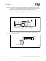
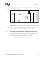
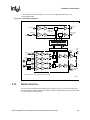
3. Insert the jumper (shunt) for J22 on the Master Power Clip (this jumper connects the two bare
pins enabling the Li-ion battery.).
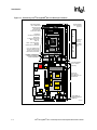
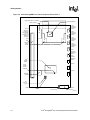
Figure 2-7. Master Power Clip Location
Master Power
Clip
Reset
Switch
J22
S9
Video Out
Header
J2
J18
(Momentary)
LCD
Cable
Connector
140-pin
Expansion
Header for
Intel®
StrongARM®
SA-1111
Development
Module or
other
Daughter
Card
4. See the Readme.txt file for success and failure indications of start-up diagnostic results and
how to proceed.
To disconnect power, remove the jumper for J22 and wait for the super cap to discharge (typically
less than 5 minutes).
Note:
2.3
If sleep mode was entered as a result of VDD_FAULT or BATT_FAULT signals, GPIO 0 and
GPIO 1 are the only wake up events that can bring the SA-1110 out of sleep mode.
Installing the StrataFlash™ Memory Components
Use the following procedure to install the StrataFlash memory components into the E11 and E12
sockets:
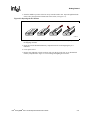
1. Power down the module and remove the jumpe for J22, if it is installed.
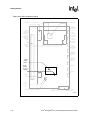
2. Locate the E11 socket on side 1 of the SA-1110 Evaluation Board.
Intel® StrongARM® SA-1110 Development Board User’s Guide
2-9