1
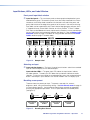
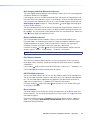
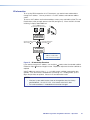
Programming Guide
This section describes:
•
RS-232 Link
•
Ethernet Link
•
Symbols
•
Switcher-Initiated Messages
•
Host-to-Switcher Instructions
•
Switcher Error Responses
•
Using the Command and Response Table
RS-232 Link
The switcher’s rear panel Remote port 9-pin D female connector (see figure 26) can be
connected to the RS-232 serial port output of a host device, such as a computer running
the HyperTerminal utility or a control system. This connection makes software control of the
switcher possible.
REMOTE
RS-232/RS-422
9
6
5
1
Pin RS-232 Function
RS-422 Function
1
— Not used
—
Not used
2
TX Transmit data
TX– Transmit data (–)
3
RX Receive data
RX– Receive data (–)
4
— Not used
—
Not used
5
Gnd Signal ground Gnd Signal ground
6
— Not used
—
Not used
7
— Not used
RX+ Receive data (+)
8
— Not used
TX+ Transmit data (+)
9
— Not used
—
Not used
Figure 26. Remote Connector Pin Arrangement
The protocol is 9600 baud, 8-bit, 1 stop bit, no parity, and no flow control.
ISM 482 Integrated Scaling Matrix Switcher • Programming Guide
31