1
User Guide
Scaling Matrix Switchers
ISM 482
Integrated Scaling Matrix Switcher
No Photo
Available yet
68-576-01 Rev. H
03 13
Safety Instructions
Safety Instructions • English
WARNING: This symbol, , when used on the product, is intended
to alert the user of the presence of uninsulated dangerous voltage
within the product’s enclosure that may present a risk of electric
shock.
ATTENTION: This symbol, , when used on the product, is intended
to alert the user of important operating and maintenance (servicing)
instructions in the literature provided with the equipment.
Chinese Simplified(简体中文)
警告:
产品上的这个标志意在警告用户该产品机壳内有暴露的危险
电压,有触电危险。
注 意:
产 品 上 的 这个 标 志 意 在 提 示用 户设 备 随 附 的 用 户手 册 中 有
重要的操作和维护(维修)说明。
关于我们产品的安全指南、遵循的规范、EMI/EMF 的兼容性、无障碍
使用的特性等相关内容,敬请访问 Extron 网站 www.extron.com,参见 Extron
For information on safety guidelines, regulatory compliances, EMI/EMF
compatibility, accessibility, and related topics, see the Extron Safety and
Regulatory Compliance Guide, part number 68-290-01, on the Extron
website, www.extron.com.
安全规范指南,产品编号 68-290-01。
Instructions de sécurité • Français
Chinese Traditional(繁體中文)
AVERTISSEMENT: Ce pictogramme,
, lorsqu’il est utilisé sur le
produit, signale à l’utilisateur la présence à l’intérieur du boîtier
du produit d’une tension électrique dangereuse susceptible de
provoquer un choc électrique.
ATTENTION: Ce pictogramme,
, lorsqu’il est utilisé sur le produit,
signale à l’utilisateur des instructions d’utilisation ou de maintenance
importantes qui se trouvent dans la documentation fournie avec le
matériel.
Pour en savoir plus sur les règles de sécurité, la conformité à la
réglementation, la compatibilité EMI/EMF, l’accessibilité, et autres sujets
connexes, lisez les informations de sécurité et de conformité Extron,
réf. 68-290-01, sur le site Extron, www.extron.fr.
警告:
若產品上使用此符號,是為了提醒使用者,產品機殼內存在著
可能會導致觸電之風險的未絕緣危險電壓。
注意
若產品上使用此符號,是為了提醒使用者。
有關安全性指導方針、法規遵守、EMI/EMF 相容性、存取範圍和相關主題的詳細
資訊,請瀏覽 Extron 網站:www.extron.com,然後參閱《Extron 安全性與法
規遵守手冊》,準則編號 68-290-01。
Japanese
警告: この記号
が製品上に表示されている場合は、筐体内に絶縁されて
いない高電圧が流れ、感電の危険があることを示しています。
Sicherheitsanweisungen • Deutsch
WARNUNG: Dieses Symbol
auf dem Produkt soll den Benutzer
darauf aufmerksam machen, dass im Inneren des Gehäuses dieses
Produktes gefährliche Spannungen herrschen, die nicht isoliert sind
und die einen elektrischen Schlag verursachen können.
VORSICHT: Dieses Symbol
auf dem Produkt soll dem Benutzer in
der im Lieferumfang enthaltenen Dokumentation besonders wichtige
Hinweise zur Bedienung und Wartung (Instandhaltung) geben.
Weitere Informationen über die Sicherheitsrichtlinien, Produkthandhabung,
EMI/EMF-Kompatibilität, Zugänglichkeit und verwandte Themen finden Sie
in den Extron-Richtlinien für Sicherheit und Handhabung (Artikelnummer
68-290-01) auf der Extron-Website, www.extron.de.
Instrucciones de seguridad • Español
ADVERTENCIA: Este símbolo,
, cuando se utiliza en el producto,
avisa al usuario de la presencia de voltaje peligroso sin aislar dentro
del producto, lo que puede representar un riesgo de descarga
eléctrica.
ATENCIÓN: Este símbolo,
, cuando se utiliza en el producto, avisa
al usuario de la presencia de importantes instrucciones de uso
y mantenimiento recogidas en la documentación proporcionada
con el equipo.
Para obtener información sobre directrices de seguridad, cumplimiento
de normativas, compatibilidad electromagnética, accesibilidad y
temas relacionados, consulte la Guía de cumplimiento de normativas
y seguridad de Extron, referencia 68-290-01, en el sitio Web de Extron,
www.extron.es.
注意: この記号
が製品上に表示されている場合は、本機の取扱説明書に
記載されている重要な操作と保守(整備)の指示についてユーザーの
注意を喚起するものです。
安全上のご注意、法規厳守、EMI/EMF適合性、その他の関連項目に
ついては、エクストロンのウェブサイトwww.extron.jpより
『 Extron Safety and Regulatory Compliance Guide 』(P/N 68-290-01) をご覧ください。
Korean
경고: 이 기호
, 가 제품에 사용될 경우, 제품의 인클로저 내에 있는
접지되지 않은 위험한 전류로 인해 사용자가 감전될 위험이 있음을
경고합니다.
주의:
이 기호
, 가 제품에 사용될 경우, 장비와 함께 제공된 책자에 나와
있는 주요 운영 및 유지보수(정비) 지침을 경고합니다.
안전 가이드라인, 규제 준수, EMI/EMF 호환성, 접근성, 그리고 관련
항목에 대한 자세한 내용은 Extron 웹 사이트(www.extron.com)의
Extron 안전 및 규제 준수 안내서, 68-290-01 조항을 참조하십시오.
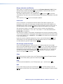
FCC Class A Notice
This equipment has been tested and found to comply with the limits for a Class A digital
device, pursuant to part 15 of the FCC rules. The Class A limits provide reasonable
protection against harmful interference when the equipment is operated in a commercial
environment. This equipment generates, uses, and can radiate radio frequency energy and,
if not installed and used in accordance with the instruction manual, may cause harmful
interference to radio communications. Operation of this equipment in a residential area is
likely to cause interference; the user must correct the interference at his own expense.
NOTE: This unit was tested with shielded I/O cables on the peripheral devices. Shielded
cables must be used to ensure compliance with FCC emissions limits.
For more information on safety guidelines, regulatory compliances, EMI/EMF
compatibility, accessibility, and related topics, see the Extron Safety and
Regulatory Compliance Guide on the Extron website.
Specifications Availability
Product specification are available on the Extron website, www.extron.com.
Conventions Used in this Guide
Notifications
The following notifications are used in this guide:
CAUTION: A caution indicates a situation that may result in minor injury.
ATTENTION: Attention indicates a situation that may damage or destroy the product or
associated equipment.
NOTE: A note draws attention to important information.
Software Commands
Commands are written in the fonts shown here:
^AR Merge Scene,,Op1 scene 1,1 ^B 51 ^W^C
[01] R 0004 00300 00400 00800 00600 [02] 35 [17] [03]
E X! *X1@* X1%* X1** X1^ CE}
NOTE: For commands and examples of computer or device responses mentioned
in this guide, the character “0” is used for the number zero and “O” is the capital
letter “o.”
Computer responses and directory paths that do not have variables are written in the font
shown here:
Reply from 208.132.180.48: bytes=32 times=2ms TTL=32
C:\Program Files\Extron
Variables are written in slanted form as shown here:
ping xxx.xxx.xxx.xxx —t
SOH R Data STX Command ETB ETX
Selectable items, such as menu names, menu options, buttons, tabs, and field names are
written in the font shown here:
From the File menu, select New.
Click the OK button.
Copyright
© 2013 Extron Electronics. All rights reserved.
Trademarks
All trademarks mentioned in this guide are the properties of their respective owners.
The following registered trademarks(R), registered service marks(SM), and trademarks(TM) are the property of RGB Systems, Inc. or Extron Electronics:
Registered Trademarks (®)
AVTrac, Cable Cubby, CrossPoint, eBUS, EDID Manager, EDID Minder, Extron, Flat Field,GlobalViewer, Hideaway, Inline, IP Intercom, IP Link, Key
Minder, LockIt, MediaLink, PoleVault, PURE3, Quantum, SoundField, System Integrator, TouchLink, V-Lock, VersaTools, VN-Matrix, VoiceLift,
WallVault, WindoWall
Registered Service Mark(SM) : S3 Service Support Solutions
Trademarks (™)
AAP, AFL (Accu-Rate Frame Lock), ADSP (Advanced Digital Sync Processing), AIS (Advanced Instruction Set), Auto-Image, CDRS (Class D Ripple
Suppression), DDSP (Digital Display Sync Processing), DMI (Dynamic Motion Interpolation), Driver Configurator, DSP Configurator, DSVP (Digital
Sync Validation Processing), FastBite, FOXBOX, IP Intercom HelpDesk, MAAP, MicroDigital, PowerCage, ProDSP, QS-FPC (QuickSwitch Front
Panel Controller), Scope-Trigger, SIS, Simple Instruction Set, Skew-Free, SpeedMount, SpeedNav, SpeedSwitch, Triple-Action Switching, XTP, XTP
Systems, XTRA, ZipCaddy, ZipClip
Contents
Introduction............................................................ 1
About This Guide................................................. 1
About the Switcher.............................................. 1
Features.............................................................. 3
Installation............................................................... 5
Mounting the Switcher......................................... 5
Tabletop Placement......................................... 5
Rack Mounting................................................ 5
Cabling and Rear Panel Views............................. 6
Input Connections........................................... 6
Standard Output Connections......................... 8
Optional Output Connection............................ 9
Ethernet Connection........................................ 9
RS-232 Connection....................................... 10
Configuration..................................................... 10
Operation............................................................... 11
Front Panel Controls and Indicators................... 11
Video/Audio Selection Button and LEDs........ 12
Output Buttons and LEDs.............................. 12
Input Buttons, LEDs, and Label Window....... 13
Black/Mute Button and LEDs........................ 14
Picture Adjustment Buttons........................... 14
LCD Display................................................... 15
Menu Control Buttons................................... 15
Adjustment Knobs......................................... 15
Front Panel Operations...................................... 15
Power............................................................ 15
Menu System Overview................................. 16
Picture Adjustments....................................... 25
Front Panel Security Lockout
(Executive Mode).......................................... 26
IP Information................................................ 27
Optimizing the Video......................................... 28
Setting up a DVD source............................... 29
Optimizing the Audio......................................... 29
Troubleshooting................................................. 29
General Checks............................................. 30
Specific Problems.......................................... 30
Programming Guide............................................ 31
RS-232 Link...................................................... 31
Ethernet Link..................................................... 32
Ethernet Connection...................................... 32
Default Address............................................. 32
Symbols............................................................ 33
Switcher-Initiated Messages.............................. 34
Power-up....................................................... 34
Ties Creation................................................. 34
Input and Output Video Type......................... 34
Picture Adjustments....................................... 34
RGB Delay..................................................... 36
Test Pattern................................................... 36
Audio Gain and Attenuation........................... 36
Video and Audio Mute................................... 36
PAL Film Mode.............................................. 36
Automated Adjustments................................ 36
Host-to-Switcher Instructions............................ 37
Switcher Error Responses................................. 37
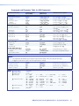
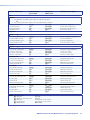
Using the Command and Response Table......... 37
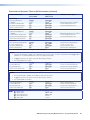
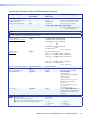
Command and Response Table
for SIS Commands....................................... 38
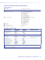
Command and Response Table
for IP SIS Commands................................... 44
Command and Response Table
for Special Function SIS Commands............ 45
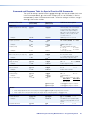
Command and Response Table
for Advanced Instruction Set Commands..... 46
ISM 482 Integrated Scaling Matrix Switcher • Table of Contents
v
Switcher Software............................................... 47
Maintenance and Modifications...................... 64
Control Software for Windows®...............................................47
Installing the Software.................................... 47
Software Operation via Ethernet.................... 48
Using the Control Program............................ 49
Using the Help Program................................ 51
Button-Label Generator..................................... 51
Installing the Software.................................... 51
Using the Software........................................ 52
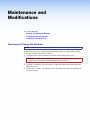
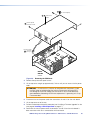
Opening and Closing the Switcher..................... 64
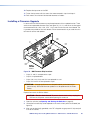
Installing a Firmware Upgrade............................ 66
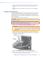
Installing a DVI Output Card............................... 67
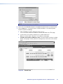
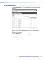
HTML Operation.................................................. 53
Loading the Startup (Control) Page.................... 53
Control Page..................................................... 55
Creating a Tie................................................ 55
Changing the RGB Delay............................... 55
Blacking out the Screen and
Muting the Audio.......................................... 55
Freezing the Output....................................... 56
Outputting a Test Pattern............................... 56
Previewing the Scan Rate.............................. 56
Using Blue-Only Mode................................... 56
Executive Mode............................................. 56
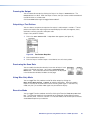
System Configuration Page............................... 57
Administration Fields...................................... 57
ISM IP Settings Fields.................................... 58
File Management Page...................................... 59
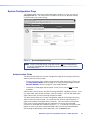
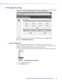
I/O Configuration Page...................................... 60
Input Configuration........................................ 60
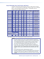
Output Resolution, Rate, Sync Format, and
Polarity......................................................... 61
Ethernet Connection.......................................... 69
Cabling.............................................................. 69
Determining Default Addresses.......................... 70
Pinging to Determine
the Switcher IP Address............................... 70
Pinging to Determine
the Web IP Address...................................... 70
Connecting as a Telnet Client............................ 71
Telnet Tips..................................................... 71
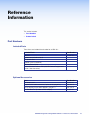
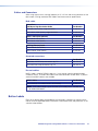
Reference Information....................................... 73
Part Numbers.................................................... 73
Included Parts............................................... 73
Optional Accessories..................................... 73
Cables and Connectors................................. 74
Button Labels.................................................... 74
Introduction
This section describes:
•
About This Guide
•
About the Switcher
•
Features
About This Guide
This manual contains installation, configuration, and operating information for the Extron
ISM 482 Integration Scaling Matrix Switcher.
In this manual, the terms “switcher” and “ISM” are used interchangeably to refer to the
ISM 482.
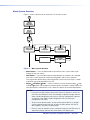
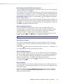
About the Switcher
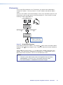
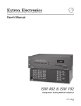
The ISM 482 is an eight-input, two-independently-scaled-output, video and stereo or mono
audio matrix switcher. Figure 1 on the next page shows a typical ISM 482 application. The
switchers accept high resolution RGB video, YUV (component) video, S-video (Y/C), and
composite video inputs; scale the inputs; and output RGBHV or RGBS video and stereo
audio. Triple-Action Switching™ (RGB delay) blanks the screen during the switch to prevent
distracting video glitches. The switcher’s two independent scalers permit differing video
formats on each input to be displayed in different resolutions on different projectors.
Each video input is individually configurable to allow for different video formats. The ISM
allows analog RGBHV, RGBS, RGsB, and RGBcvS video, component video, S-video, and
composite video signals to be displayed on a device with a fixed resolution and aspect ratio,
such as a liquid crystal display (LCD) projector, digital light processor (DLP) projector, or
plasma display.
The ISM provides two separate outputs. The selected input can be switched to either or
both outputs. With an optional DVI output card, the ISM converts the scaled image to DVI
as an additional set of output 1 signals.
The switcher inputs all valid video signal formats on eight sets of five BNC connectors. The
ISM 482 scales the input up or down to a wide variety of output resolutions and rates. The
switcher outputs the scaled video, as RGBHV or RGBS, on two sets of output connectors,
consisting of five BNCs and a 15-pin HD connector. These connectors share identical
outputs.
Several of the output resolutions and rates include the Extron Accu-RATE Frame
Lock™ (AFL™), a proprietary technology that locks the output frame rate to the refresh
rate of input 1, solving the image tearing problem that can result from different input
and output rates. The switcher features HDTV 576p, 720p, 1080p, and 1080i outputs.
ISM 482 Integrated Scaling Matrix Switcher • Introduction
1
Projector
Extron
ISM 482
Projector
1
TS 2
TPU
OU
1
DVI
R
OUT
2
R
G
232
RS-
G
B
B
8
7
6
DVD Player
G
LINK
ACT
Control System
(RS-232)
V
H/H
V
H/H
B
B
V
H/H
B
V
H/H
V
H/H
B
8
V
H/H
B
7
V
H/H
Hz
LAN/WAN
Network/
Internet
6
5
V
H/H
50/60
240 MAX.
100- 1.2A
ET
B
B
G
G
ERN
B
G
R
G
ETH
V
G
G
G
R
R
V
H/H
V
R
R
R
2
1
V
H/H
R
R
UTS 5
INP
4
3
4
3
2
1
Codec
Extron
RGB 112xi
VCR
Laptop
Figure 1.
Podium PC
Typical ISM 482 Integration Scaling Matrix Switcher Application
The ISM receives and outputs the stereo audio on 5-pole captive screw connectors.
For upscaling, the ISM 482 converts the horizontal and vertical sync timing and the number
of lines of the lower-resolution video input to match the native resolution of the display. This
produces an undistorted, brighter picture than an unscaled input would.
For downscaling, the ISM 482 accepts any computer resolution, up to 1600 x 1200, with
horizontal scan rates up to 100 kHz and vertical scan rates up to 120 Hz, and converts the
input to match the native resolution of the display.
The switcher is ideal for displaying images on projectors with limited display resolutions,
such as LCD projectors, DLP projectors, and plasma projectors.
The switcher features built-in test patterns to aid in monitor or projector set-up and
evaluation.
The switcher is housed in a rack-mountable, 3U high, 17.5 inch wide, metal enclosure. The
ISM has an internal 100VAC to 240VAC, 50/60 Hz, 30 watts power supply that provides
worldwide power compatibility.
ISM 482 Integrated Scaling Matrix Switcher • Introduction
2
Features
•
•
Inputs
•
Video inputs — The ISM switches among eight fully-configurable RGB, HDTV
component video, component video, S-video, and composite video inputs on five
BNC connectors per input.
•
Audio inputs — The ISM switches among eight balanced or unbalanced stereo or
mono audio inputs on 5-pole captive screw connectors.
Outputs
•
Standard video outputs — The ISM outputs individually scaled video signals as
RGBHV or RGBS. Two sets of BNC connectors and two 15-pin HD connectors are
provided. One set of BNC connectors and one 15-pin HD connector display the
output 1 image, and the other set of BNC connectors and 15-pin HD connector
display the output 2 image.
•
Optional DVI video output — If you install the optional DVI output card, a single
buffered DVI-D signal can be output as an additional output 1 image.
NOTE: For output resolutions with less than 1024 pixels horizontally, the
optional DVI output’s true horizontal resolution is limited to 1024 pixels. For
the 1365 x 1024, 1080p, and 1080i output resolutions, the optional DVI
output’s true horizontal resolution is limited to 1280 pixels. The DVI card
outputs all other selected resolutions normally (see the table on page 20).
•
Audio outputs — The ISM outputs the selected unamplified, line level, balanced or
unbalanced stereo or mono audio on 5-pole captive screw connectors.
•
Accu-RATE Frame Lock™ (AFL™) — A patented technology exclusive to Extron that
solves frame rate conversion issues experienced by video scalers. When video input
and output refresh rates differ, occasionally the two rates cross over each other. The
result is a glitch or image freeze on the display. AFL solves this problem by locking the
output frame rate to the frame rate of input 1.
•
Dynamic Motion Interpolation™ (DMI™) — This video processing technique is an
advanced motion prediction and compensation method that treats motion content and
still content with different algorithms to yield high fidelity images.
•
3:2 pulldown detection for NTSC video sources and 2:2 film detection for PAL
— These advanced, patent pending, film mode processing features help maximize
image detail and sharpness for video sources that originated from film. When film is
converted to NTSC video, the film frame rate has to be matched to the video frame
rate in a process called 3:2 pulldown. Jaggies and other image artifacts can result
if conventional deinterlacing techniques are used on film-source video. The ISM’s
advanced film mode processing recognizes signals that originated from film. The ISM
then applies video processing algorithms that optimize the conversion of video that was
made with the 3:2 pulldown process. This results in richly detailed images with sharply
defined lines.
A similar process, 2:2 film detection, is used for PAL film-source video.
•
Audio follow and breakaway — Audio switching can follow its corresponding video
input signal or it can be broken away from the video input. Audio breakaway switching
can be done via front panel control or under RS-232 or Ethernet remote control.
•
Audio gain/attenuation — Users can set the input level of audio gain or attenuation
(-24 dB to +9 dB) via the RS-232 port, Ethernet link, or from the front panel. Individual
input audio levels can be adjusted so there is no noticeable volume difference between
sources.
ISM 482 Integrated Scaling Matrix Switcher • Introduction
3
•
Ethernet port — Supports connection to an Ethernet LAN so that the switcher can be
accessed and operated from anywhere in the world with a computer using a standard
Internet browser.
•
Quad-standard video decoder — The switcher uses a digital, four-line adaptive comb
filter that can decode NTSC 3.58, NTSC 4.43, PAL, and SECAM.
•
Test patterns — The switcher features built-in test patterns to aid in monitor or
projector setup and evaluation.
•
Blue mode — The switcher can be set to output the blue video signal and sync
signal(s) only, to help installers calibrate the monitor or projector.
•
Triple-Action Switching™ (RGB delay) — RGB delay mutes the R, G, and B video
planes to blank the screen while the scaler locks to the new sync, so that a noise-filled
scramble is not shown on the monitor during the transition. The time delay between the
RGB and sync signals is user adjustable up to five seconds under front panel, Simple
Instruction Set (SIS™), and Windows program control.
•
Auto memories — The eight inputs support 16 auto-recall memories each, based on
the incoming frequency. Information on sizing, centering, detail, contrast, and brightness
is saved.
•
Auto Image™ — The auto imaging feature automatically sizes and centers the selected
input to fill the screen. Auto imaging can be manually initiated on the current input, or
can be enabled to globally size and center each new input signal automatically.
•
Memory presets — The ISM 482 has memory for up to 128 presets that allow the
user to use RS-232 commands to save and recall color, tint, contrast, brightness,
centering, sizing, and filtering information.
•
Aspect ratio memories — Three memories for each input save different color, tint,
contrast, brightness, detail, size, and centering settings.
•
Freeze mode (under SIS and Windows program control only) — Locks the output
display to the selected image. Once frozen, an input can be removed without losing the
output image. This feature lets the ISM store a still image.
•
Rack mounting — The 3U high switcher can be mounted in any conventional 19 inch
wide rack.
ISM 482 Integrated Scaling Matrix Switcher • Introduction
4
Installation
This section describes:
•
Mounting the Switcher
•
Cabling and Rear Panel Views
•
Configuration
Mounting the Switcher
Four uninstalled rubber feet are included with the switcher. If you are going to rack mount
the switcher, mount it before you cable it (see “Rack Mounting,” below), and do not install
the rubber feet. If you are not rack mounting the switcher, see “Tabletop Pacement,” below.
Tabletop Placement
For tabletop placement, install the self-adhesive rubber feet/pads (provided) onto the four
corners of the bottom of the switcher.
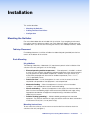
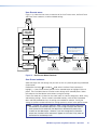
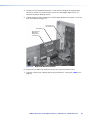
Rack Mounting
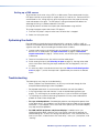
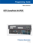
UL guidelines
The following Underwriters Laboratories (UL) requirements pertain to the installation of the
switcher into a rack (see figure 2 on the next page).
•
Elevated operating ambient temperature — If the equipment is installed in a closed
or multi-unit rack assembly, the operating ambient temperature of the rack environment
may be greater than room ambient temperature. Therefore, install the switcher in an
environment compatible with the maximum ambient temperature (Tma = +122 °F,
+50°C) specified by Extron.
•
Reduced air flow — Install the equipment in a rack so that the amount of air flow
required for safe operation of the equipment is not compromised.
•
Mechanical loading — Mount the equipment in the rack so that a hazardous
condition is not achieved due to uneven mechanical loading.
•
Circuit overloading — Connect the equipment to the supply circuit and consider the
effect that circuit overloading might have on overcurrent protection and supply wiring.
Appropriate consideration of equipment nameplate ratings should be used when
addressing this concern.
•
Reliable earthing (grounding) — Maintain reliable grounding of rack-mounted
equipment. Pay particular attention to supply connections other than direct connections
to the branch circuit (that is, use of power strips).
Mounting instructions
To rack mount the switcher, use two screws on each end of the switcher to attach the
switcher to the rack (see figure 2).
ISM 482 Integrated Scaling Matrix Switcher • Installation
5
ST
JU
AD
2
48 X
ISMMATRI
G
IN
ER
FILT
N
IO
NT
CE
XT
SIZE
1
VIDE
R/
LO
CO NT
TI
NE
NU
ME
O
UT
TP
OU
8
S
UT
INP
T/
BRNT
CO
AL
SC
AT
GR
TE
IN
ER
7
6
O
AU
5
2
DI
8
4
7
3
6
2
5
1
4
K
AC
BL
3
2
1
TE
MU
Figure 2.
Mounting the Switcher
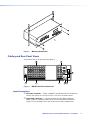
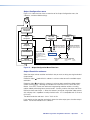
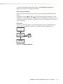
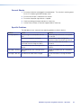
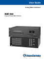
Cabling and Rear Panel Views
All connectors are on the rear panel (see figure 3).
2
1
4
3
2
INPUTS
4
OUTPUTS
8
7
6
5
1
2
1
R/R-Y
R/R-Y
R/R-Y
R/R-Y
R/R-Y
R/R-Y
R/R-Y
R/R-Y
R
R
G/Y
VID
G/Y
VID
G/Y
VID
G/Y
VID
G/Y
VID
G/Y
VID
G/Y
VID
G/Y
VID
G
G
B/C
B-Y
B/C
B-Y
B/C
B-Y
B/C
B-Y
B/C
B-Y
B/C
B-Y
B/C
B-Y
B/C
B-Y
B
B
H/HV
H/HV
H/HV
H/HV
H/HV
H/HV
V
V
V
V
V
2
DVI OUT
6
RS-232
100- 240
50/60 Hz
1.2A MAX.
V
V
V
V
V
H/HV
H/HV
H/HV
H/HV
ETHERNET
1
2
3
4
5
6
7
8
LINK
ACT
1
3
Figure 3.
5
7
8
ISM 482 Rear Panel Connectors
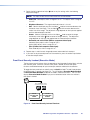
Input Connections
a AC power connector — Plug a standard IEC power cord into this connector to
connect the switcher to a 100 to 240 VAC, 50 Hz or 60 Hz power source.
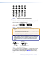
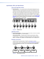
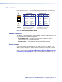
b Input video connectors — Connect computer or RGB video, component
video, S-video, or composite video sources to these female BNC connectors.
Figure 4 on the next page shows how to connect the various video formats.
ISM 482 Integrated Scaling Matrix Switcher • Installation
6
R/R-Y
R/R-Y
R/R-Y
R/R-Y
R/R-Y
G/Y
VID
G/Y
VID
G/Y
VID
G/Y
VID
G/Y
VID
B/C
B-Y
B/C
B-Y
B/C
B-Y
B/C
B-Y
B/C
B-Y
H/HV
H/HV
H/HV
H/HV
H/HV
V
RGBHV
Video
V
RGBS or
RGBcvS
Video
Figure 4.
V
V
RGsB or
Component
Video
S-Video
V
Composite
Video
Connections for Various Input Video Formats
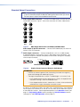
c Input audio connectors — Connect balanced or unbalanced stereo or mono audio
sources to these 3.5 mm, 5-pole captive screw connectors. Connectors are included
with the seamless switcher, but you must supply the audio cable. Figure 5 shows how
to wire a connector for the appropriate input type.
Unbalanced Stereo Input
R
Figure 5.
R
Do not tin the wires!
Tip
Ring
Sleeves
Tip
Ring
L
L
Tip
Sleeve
Tip
Sleeve
Balanced Stereo Input
Captive Screw Connectors Wiring for Inputs
ATTENTION: The length of exposed wires is critical. The ideal length is 3/16 inch
(5 mm).
• If the stripped section of wire is longer than 3/16 inch, the exposed wires may
touch, causing a short circuit between them.
• If the stripped section of wire is shorter than 3/16 inch, wires can be easily
pulled out even if tightly fastened by the captive screws.
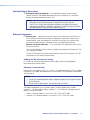
NOTE: When making connections for the seamless switcher from existing audio
cables, see figure 6. A mono audio connector consists of the tip and sleeve. A
stereo audio connector consists of the tip, ring and sleeve. The tip, ring, and
sleeve wires are also shown on the captive screw audio connector diagram,
figure 5.
Tip (+)
Ring (-)
Tip (+)
Sleeve ( )
Sleeve ( )
RCA Connector
Figure 6.
3.5 mm Stereo Plug Connector
(balanced)
Phono Audio Connectors
The audio level for each input can be individually set, via the front panel, the Ethernet
link, or the RS-232 link, to ensure that the level on the output does not vary from
input to input. See the applicable portions of the Operation section (see page 17),
Programming Guide section (see page 42), and Switcher Software section (see
page 54).
ISM 482 Integrated Scaling Matrix Switcher • Installation
7
Standard Output Connections
NOTE: The two Output 1 outputs, consisting of five BNC connectors and a
15‑pin HD connector, output the identical video signal and the same sync format.
The two Output 2 outputs are also identical to each other.
d Video output BNC connectors — Connect RGB video displays to these two sets of
female BNC connectors. Figure 7 shows how to connect the various video formats.
R
R
G
G
B
B
H/HV
H/HV
V
RGBHV
Video
V
RGBS
Video
Figure 7.
BNC Output Connections for RGBHV and RGBS Video
Video output 15-pin HD connectors — Connect RGB video displays to these two
female 15-pin HD connectors.
e Audio output connectors — Connect audio devices, such as an audio amplifier
or powered speakers, to these two 3.5 mm, 5-pole captive screw connectors. The
connectors output the selected unamplified, line level audio. See figure 8 to properly
wire an output connector.
No Ground Here
R
Tip
Ring
Sleeves
Tip
Ring
L
Figure 8.
R
No Ground Here
Unbalanced Stereo Output
L
Do not tin the wires!
Tip
Sleeves
Tip
Balanced Stereo Output
Captive Screw Connector Wiring for Audio Output
ATTENTION: • Connect the sleeve to ground (Gnd). Connecting the sleeve to a negative (-)
terminal will damage the audio output circuits.
• The length of exposed wires is critical. The ideal length is 0.2 inches (5 mm).
• If the stripped section of wire is longer than 0.2 inches, the exposed wires
may touch, causing a short circuit between them.
• If the stripped section of wire is shorter than 0.2 inches, wires can be easily
pulled out even if tightly fastened by the captive screws.
By default, the audio output follows the video switch. Audio breakaway, commanded via
the front panel, the Ethernet link, or the RS-232 link, allows you to select from any one
of the audio input sources. See the applicable portions of the Operation section (see
page 12), Programming Guide section (see page 38), Switcher Software section
(see page 50), and HTML Operation section (page 55).
ISM 482 Integrated Scaling Matrix Switcher • Installation
8
Optional Output Connection
f DVI output connector (optional) — If the optional DVI output card is installed,
connect a DVI/DFP-compatible video display to this DVI connector. This connector
outputs the image selected for output 1 only.
NOTE: For output resolutions with less than 1024 pixels horizontally, the optional
DVI output’s true horizontal resolution is limited to 1024 pixels. For the
1365 x 1024, 1080p, and 1080i output resolutions, the optional DVI output’s
true horizontal resolution is limited to 1280 pixels. The DVI card outputs all other
selected resolutions normally (see the table on page 20).
Ethernet Connection
g Ethernet port — If desired, connect the switcher to an Ethernet LAN or WAN via this
RJ-45 connector. Ethernet control allows the operator to control the switcher from a
remote location. When connected to an Ethernet LAN or WAN, the switcher can be
accessed and operated from a computer running a standard Internet browser.
Ethernet connection indicators — The Link and Act LEDs indicate the status of the
Ethernet connection.
The Link LED indicates that the switcher is properly connected to an Ethernet LAN. This
LED should light steadily.
The Act LED indicates transmission of data packets on the RJ-45 connector. This LED
should flicker as the switcher communicates.
Cabling and RJ-45 connector wiring
It is vital that your Ethernet cables be the correct cables, and that they be properly
terminated with the correct pinout.
Choosing a network cable
Ethernet links use Category (CAT) 3, 4, 5, 5e, or 6, unshielded twisted pair (UTP) or shielded
twisted pair (STP) cables, terminated with RJ-45 connectors. Ethernet cables are limited to
328 feet (100 m).
NOTES:
• Do not use standard telephone cables. Telephone cables will not support Ethernet
or Fast Ethernet.
• Do not stretch or bend cables. Transmission errors can occur.
The cable used depends on your network speed. The ISM supports both 10 Mbps
(10Base-T — Ethernet) and 100 Mbps (100Base-T — Fast Ethernet), half-duplex and fullduplex, Ethernet connections.
•
10Base-T Ethernet requires, at a minimum, CAT 3 UTP or STP cable.
•
100Base-T Fast Ethernet requires, at a minimum, CAT 5 UTP or STP cable.
ISM 482 Integrated Scaling Matrix Switcher • Installation
9
Wiring the network cable
The cable can be terminated as either a patch cable or a crossover cable (see figure 9) and
must be properly terminated for your application:
•
Patch (straight) cable — Connection of the ISM to an Ethernet hub, router, or
switcher that also hosts a controlling computer
•
Crossover cable — Direct connection between the ISM and a controlling computer
Crossover Cable
Pins:
12345678
Pin
Insert Twisted
Pair Wires
Straight-through Cable
End 2
Wire color
Pin
End 1
Wire color
End 2
Wire color
1 White-green
White-orange
1 White-orange
White-orange
2 Green
Orange
2
Orange
Orange
3 White-orange
White-green
3 White-green
White-green
4 Blue
Blue
4 Blue
Blue
5 White-blue
White-blue
5 White-blue
White-blue
6 Orange
Green
6
Green
7 White-brown
White-brown
7 White-brown
White-brown
8 Brown
Brown
8 Brown
Brown
T568A
RJ-45
Connector
Figure 9.
End 1
Wire color
T568B
Green
T568B
A cable that is wired as T568A at one end
and T568B at the other (Tx and Rx pairs
reversed) is a "crossover" cable.
T568B
A cable that is wired the same at both ends is
called a "straight-through" cable, because
no pin/pair assignments are swapped.
RJ-45 Connector Pinout Tables
RS-232 Connection
h Remote port — Connect a host device, such as a computer or touch panel control,
to the integration scaling matrix switcher via this 9-pin D connector for serial RS-232
control (see figure 10).
Pin
1
2
3
4
5
6
7
8
9
RS-232
—
TX
RX
—
Gnd
—
—
—
—
Function
Not used
Transmit data
Receive data
Not used
Signal ground
Not used
Not used
Not used
Not used
5
1
9
6
Female
1
6
5
9
Male
Figure 10. Remote Port Pin Assignments
See Programming Guide on page 31, for definitions of the SIS commands and
Switcher Software on page 47, to install and use the control software.
Configuration
The ISM can be configured using either the front panel controls, the SIS, or the Windows
Control program (see the Operation section on page 16, the Programming Guide section
on page 38, the Switcher Software section on page 49, and the HTML Operation
section on page 60
ISM 482 Integrated Scaling Matrix Switcher • Installation
10
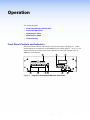
Operation
This section describes:
•
Front Panel Controls and Indicators
•
Front Panel Operations
•
Optimizing the Video
•
Optimizing the Audio
•
Troubleshooting
Front Panel Controls and Indicators
All of the switcher’s controls and indicators are on the front panel (see figure 11). A label
window above the input buttons can be labeled with text and/or graphics. The 20 x 4 LCD
display indicates the switcher status, menu selections, the data rate, and the status of
additional system features.
3
7
6
INPUTS
1
BLACK
1
2
3
4
5
6
7
8
VIDEO
MUTE
1
2
3
4
5
6
7
8
AUDIO
OUTPUTS
ADJUST
2
COLOR/
TINT
BRT/
CONT
SIZE
CENTER
FILTER
MENU
NEXT
ISM 482
INTEGRATION SEAMLESS SWITCHER
5
4
1
2
8
9
Figure 11. Integration Scaling Matrix Switcher Front Panel
ISM 482 Integrated Scaling Matrix Switcher • Operation
11
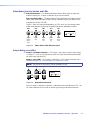
Video/Audio Selection Button and LEDs
a Video/Audio button — The Video/Audio button selects video, audio, or video and
audio for creating ties. If neither is selected, no ties can be created.
Video and Audio LEDs — The green Video LED and red Audio LED indicate whether
video, audio, video and audio, or neither will be selected using the Input buttons and
indicated by the Input LEDs (d).
Figure 12 shows the sequence displayed by the LEDs when you cycle through video
and/or audio selection by pressing the Video/Audio button repeatedly as follows.
VIDEO
VIDEO
Press
button
VIDEO
Press
button
VIDEO
Press
button
VIDEO
Press
button
LED key:
= on,
AUDIO
AUDIO
AUDIO
AUDIO
AUDIO
Default
(Video &
audio)
None
Video
only
Audio
only
Video &
Audio
= off
Figure 12. Video and/or Audio Selection Cycle
Output Buttons and LEDs
b Output 1 and Output 2 buttons — The Output 1 and Output 2 buttons select output
1 or output 2. Press an output button to select that output and automatically deselect
the other output (see figure 13).
Output 1 and 2 LEDs — The Output 1 and Output 2 LEDs indicate the output that is
selected (see figure 13). Only one Output LED can be lit at a time.
NOTE: Only one of the two outputs can be selected at a time.
1
1
1
Press
button
LED key:
OUTPUTS
2
Press
button
OUTPUTS
OUTPUTS
2
2
= on,
= off
Figure 13. Output Selection Cycle
When an output is selected, its tied input is indicated by the associated Input LED. You
can select a different input to tie to this output by pressing the desired input button.
ISM 482 Integrated Scaling Matrix Switcher • Operation
12
Input Buttons, LEDs, and Label Window
Front panel input label window
c Input label panel — This translucent panel can be removed and replaced to insert a
label behind the panel. To remove the panel, insert the Phillips-head end of an Extron
tweeker or small Phillips-head screwdriver into the hole in one end of the panel, and
gently slide the tab on the edge of the panel out of the recess in the switcher housing.
Input labels can be created easily with Extron’s button label generator software, which
is shipped with every Extron Matrix Switcher, or with any Brother® P-Touch™ labeler.
Each input can be labeled with names, alphanumeric characters, or even color bitmaps
for easy and intuitive input and output selection (see figure 14). See the Button-Label
Generator section on page 51 for details on using the label software and the Button
Labels section on page 75 for blank labels.
INPUTS
Rack DVD
(DVS 100)
1
2
3
4
5
6
7
8
1
2
3
4
5
6
7
8
Figure 14. Sample Label
Selecting an input
d Input selection buttons — The Input 1 through Input 8 buttons select the associated
input to scale and display on the selected outputs.
Input selection LEDs — The green input LEDs above the input buttons indicate
the video selection. The red input LEDs below the input buttons indicate the audio
selection. To view the input tied to the unselected output, press the unselected output
button. Both outputs’ input selections can also be viewed in the LCD display cycle.
Recalling a user preset
There are three user presets per input. The presets save color, tint, contrast,
brightness, detail, sizing, and centering settings. See User Presets menu on page 23
to save and erase presets. Cycle through and recall these memories by repeatedly
pressing the appropriate input button. The LCD panel identifies the recalled preset
(see figure 15).
Press button
Press button
Press button
3
3
3
3
User Preset #2
Recalled
User Preset #3
Recalled
User Preset #1
Recalled
User Preset #2
Recalled
Figure 15. Recalling User Presets
ISM 482 Integrated Scaling Matrix Switcher • Operation
13
Auto imaging an input
The auto imaging feature automatically sizes and centers the selected input to fill the
screen. Initiate the auto imaging feature for a specific input by pressing and holding
the appropriate input button until the LCD displays the message Auto Image Input
#n, releasing the input button, and then pressing and releasing the input button again.
The LCD displays AutoSizing and Centering Please Wait... until the operation is
complete.
Alternatively, using the menu system, you can set this feature to apply the Auto Image
adjustments to every input as it is selected (see Auto Imaging and Auto Memories
submenu on page 22).
Black/Mute Button and LEDs
e Black/Mute button and LEDs — The Black/Mute button switches the selected
output(s) to a black screen and/or muted audio. The black screen and/or mute audio is
deselected when a new input is selected.
Picture Adjustment Buttons
f The picture adjustment buttons select individual image adjustments that are adjusted
using the Adjust and Adjust knobs (i). The LEDs above these buttons light when
the button is pressed (see Picture Adjustments on page 25).
Color/Tint control button — The Color/Tint button selects the display color and tint
adjustments. The color adjustment range is from 0 to 127. The tint adjustment range is
from 0 to 255.
NOTE: The Color/Tint control affects only composite video and S-video inputs.
Brightness/Contrast control button — The Brightness/Contrast button selects the
display brightness and contrast adjustments. The adjustment range for both brightness
and contrast is from 0 to 63.
Size control button — The Size button selects the display size adjustment. The
adjustment range depends on the output resolution selected.
Center control button — The Center button selects the display centering adjustment.
The adjustment range depends on the output resolution selected.
Filter control (Detail) button — The Detail button selects the display image detail
(sharpness) adjustment. There are separate horizontal and vertical filters for RGB
and component video. There is a single filter for S-video and composite video. The
sharpness adjustment compensates for long cable runs.
•
For RGB and component video, the Adjust knob controls the horizontal filter and
the Adjust knob controls the vertical filter. The adjustment range for the horizontal
filter is from 0 to 3. The adjustment range for the vertical filter is from 0 to 7.
•
For S-video and composite video, either Adjust knob controls the filter setting. The
range of the adjustment is from 0 to 7.
ISM 482 Integrated Scaling Matrix Switcher • Operation
14
LCD Display
g Status display — The 20-column by 4-line LCD displays configuration menus and
status information (see “Front Panel Operations,” below, for details).
Menu Control Buttons
h Menu button — The Menu button enters and moves through the main menu system in
the ISM (see “Front Panel Operations,” below, for details).
Next button — The Next button steps through the submenus in the ISM menu system
(see “Front Panel Operations,” below, for details).
Adjustment Knobs
i Adjust
(horizontal) and Adjust (vertical) knobs — The Adjust and Adjust
knobs change settings when used in conjunction with the picture adjustment buttons
or the menu system. Rotate these knobs to change picture settings when one of the
picture adjustment buttons is selected. In the menu system, rotate these knobs to
scroll through the selection options and make adjustments.
Front Panel Operations
The following paragraphs detail the power-up process and then describe the menu system,
the picture adjustments, and selection of executive mode.
Power
Power is automatically applied when the power cord is connected to an AC source. When
AC power is applied, the switcher performs a self-test that blinks all of the front panel
LEDs and then lights only the LEDs for the previously selected output and the tied input.
The self-test also displays the model name, part number, and the firmware version in the
LCD display. After approximately 2 seconds, the LCD reverts to its default display cycle,
alternating between two displays: one showing the inputs selected for outputs 1 and output
2, and the other showing the selected output rates (see figure 16). An error-free power up
self-test sequence leaves all of the LEDs off, with the exception of the selected output’s and
input’s LEDs, off and the LCD cycling through the default displays.
Default Display Cycle
Power
on
Extron Electronics
ISM 482
Integration
Scaling Matrix
2
sec.
Extron Electronics
ISM 482
60-425-01
Version x.xx
2
sec.
Out #1 In # 1 RGB
0.00 kHz 0.00Hz
Out #2 In # 3 S-Video
0.00 kHz 0.00Hz
Output Rate
#1 1280 x 1024 @ 60
2
sec.
#2 1280 x 1024 @ 60
2
sec.
Figure 16. LCD Power Up and Default Display Cycle
The selected inputs for output 1 and output 2, the picture adjustments, and other current
settings are saved in nonvolatile memory. When power is applied, the latest configuration is
retrieved.
NOTE: On figure 16 and all other flowcharts in this section, solid lines indicate
screen changes initiated by the operator. Dashed lines indicate screen changes
that are the result of a timeout function.
ISM 482 Integrated Scaling Matrix Switcher • Operation
15
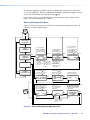
Menu System Overview
Figure 17 shows a flowchart of the main menus in the menu system.
Power
on
Extron Electronics
ISM 482
Integration
Scaling Matrix
2 sec.
Extron Electronics
ISM 482
60-425-01
Version x.xx
2 sec.
Default
Cycle
Menu
10 sec.
Video & Audio
Configuration
Menu
10 sec.
Output
Configuration
10 sec.
Menu
Advanced
Configuration
10 sec.
User Presets
Menu
Menu
10 sec.
Exit Menu
Press Next to Exit
Next
Menu
Figure 17. Menu system flowchart
•
Menu button — Press the Menu button to activate the menu system and to scroll
through the five main menus.
•
Next button — Press the Next button to move between the submenus of a selected
main menu, to activate one for viewing or configuration, and to save a selection.
Pressing the Next button during input configuration causes the current input’s number
and format type to be displayed on the LCD.
•
Adjust and Adjust knobs — When a submenu is active, rotate the Adjust knob
and Adjust knob to scroll through the submenu options and select a setting. Refer to the
menu descriptions and flowcharts in this section for specific menu control explanations.
NOTES:
• If you press the Menu button while a main menu or a submenu is active, the
next main menu becomes active. For example, the display changes from the
Video & Audio Configuration main menu or the Input Configuration submenu
(a submenu of the Video & Audio Configuration menu) to the Output
Configuration main menu.
• To return to the default screens, let the switcher remain idle for 10 seconds
until the selected screen times out; or press the Menu button until the Exit
Menu appears, then press the Next button.
• From any menu or submenu, after 10 seconds of inactivity, the ISM saves all
adjustment settings and times out to the default LCD display cycle.
ISM 482 Integrated Scaling Matrix Switcher • Operation
16
Video & Audio Configuration menu
Figure 18 is a flowchart that shows an overview of the Video & Audio Configuration menu
and the available settings.
Default
Cycle
Menu
10 sec.
Video & Audio
Configuration
10 sec.
Next Video/Audio Config
Next
Menu Input #1 Composite
Audio #3 Level -12db
Menu
NOTE: The audio is broken
away in this example.
1
Input Configuration:
Input Configuration:
Select an input to configure
by pressing an Input button.
Output
Configuration
1
If necessary, select
another input and
repeat.
2
Menu
Advanced
Configuration
Menu
User Presets
•
•
•
•
•
Rotate the knob to select
the video type.
Input video type
RGB
• Betacam 60
RGBcvS
• HDTV
YUVi
• S-video
YUVp
• Composite
Betacam 50
Rotate the knob to select
the audio level.
Input audio level
-24dB to +9dB
Menu
Menu
Exit Menu
Press Next to Exit
Next
Figure 18. Video and Audio Configuration Menu Flowchart
Input Configuration submenu
Select an input to configure by pressing and releasing an input button. Rotate the Adjust
knob while in the Input Configuration submenu to select the correct video format (RGB,
RGBcvS, YUVi, YUVp, Betacam 50, Betacam 60, HDTV, S-video, or composite video) for
the selected input. Rotate the Adjust knob to select the audio gain or attenuation value,
from -24 dB to +9 dB. The defaults for each input are RGB video and a 0 dB audio level.
ISM 482 Integrated Scaling Matrix Switcher • Operation
17
Output Configuration menu
Figure 19 is a flowchart that shows an overview of the Output Configuration menu, the
submenus, and the available settings.
Default
Cycle
Menu
10 sec.
Video & Audio
Configuration
Menu
Output
Configuration
10 sec.
10 sec.
Output #1 Resolution
Next
1280 x 1024
Refresh Rate
60 Hz
Next
Output #1 Sync Type Menu
Next
RGBHV
Sync Polarity
H Neg
V Pos
Menu
1
1
Advanced
Configuration
Output Configuration:
OUTPUTS
Menu
User Presets
Menu
Menu
Exit Menu
Press Next to Exit
If necessary, select the
other output and repeat.
2
Output resolutions
See the table on the
next page for available
combinations of
resolutions and refresh
rates.
Default: 1024x768, 60 Hz
Output Configuration:
OUTPUTS
If necessary, select the
other output and repeat.
2
Output frequencies
NOTE: Lock = AFL
Output signal format
• RGBHV
• RGBS
Polarity combinations
• H-/V- (default) • H+/V• H+/V+
• H-/V+
Next
Figure 19. Output Configuration Menu Flowchart
Output Resolution submenu
Select the output whose resolution and refresh rate you want to set by pressing the desired
Output button.
Rotate the Adjust
resolutions.
knob while this submenu is active to select one of the available output
Rotate the Adjust knob while this submenu is active to select one of the available refresh
(vertical scanning) rates. Selecting Lock enables the Extron Accu-RATE Frame Lock (AFL)
feature. Accu-RATE Frame Lock eliminates image tearing and other artifacts of scaling
motion video by eliminating frame rate conversion. It exactly matches the output rate of the
ISM to the frame rate of input 1. Select this feature if you will be using motion video sources
with a display that is capable of a variety of refresh rates. AFL is compatible with 50 Hz and
60 Hz only.
The default resolution and rate is 1024 x 768 @ 60 Hz.
If you need to set the resolution and refresh rate on the other output, press the other output
button. You do not need to exit this submenu.
ISM 482 Integrated Scaling Matrix Switcher • Operation
18
Resolution
640 x 480
800 x 600
50 Hz
56 Hz
•
•
832 x 624
848 x 480
852 x 480
1024 x 768*
1280 x 768*
1200 x 800*
1280 x 1024*
•
•
•
•
1360 x 765*
1365 x 768*
•
1366 x 768*
1365 x 1024
1400 x 1050*
576p HDTV*
•
•
720p* HDTV @ 60 Hz only
1080p HDTV @ 60 Hz only
1080i HDTV
•
•
60 Hz
75 Hz
•
•
•
•
•
•
•
•
•
•
•
•
•
•
•
•
•
85 Hz
•
•
Lock at 50/60 Hz✝ Actual DVI output
•
•
•
•
•
•
•
•
1024 x 480
1024 x 600
1024 x 624
1024 x 480
1024 x 480
1024 x 768
1280 x 768
1200 x 800
1280 x 1024
•
•
•
•
•
•
•
•
•
•
•
•
1360 x 765
1365 x 768
1366 x 768
1280 x 1024
1400 x 1050
720 x 576
1280 x 720
1280 x 1080
1280 x 540
* Native DVI output resolution
✝ The output refresh rate is auto-selected, based on the video refresh rate of input 1.
NOTES:
• For output resolutions with less than 1024 pixels horizontally, the optional DVI
output is limited to a true horizontal resolution of1024 pixels. The vertical resolution
is the selected vertical resolution. For these resolutions, the ISM DVI output is
1024 x {selected vertical size}. For example, if the output resolution is set to
640 x 480, the DVI output card’s actual resolution is 1024 × 480.
• For the 1365 x 1024, 1080p, and 1080i output resolutions, the optional DVI output
is limited to a true horizontal resolution of 1280 pixels. For these resolutions,
the ISM DVI output is 1280 x {selected vertical size}. For example, if the output
resolution is set to 1080p, the DVI output card’s actual resolution is 1280 x 1080.
• The DVI card outputs all other selected resolutions normally.
• Resolutions marked with an asterisk (*) in the table above are native DVI outputs;
the DVI output fully supports the selected horizontal and vertical resolution. The
DVI output resolution for these rates exactly matches the analog resolution.
Sync Type and Polarity submenu
Select the output whose sync type and polarity you want to set by pressing the desired
Output button.
Rotate the Adjust knob while in this submenu to select the output video type (RGBHV or
RGBS) for the selected output.
ISM 482 Integrated Scaling Matrix Switcher • Operation
19
The display or projector may require a particular combination of horizontal (H) and vertical
(V) sync signal polarities. Select the appropriate combination of positive or negative H and V
sync for the selected output by rotating the Adjust knob.
If you need to set the sync type and polarity on the other output, press the other output
button. You do not need to exit this submenu.
Advanced Configuration Menu
Figure 20 is a flowchart that shows an overview of the Advanced Configuration menu, the
submenus, and the available settings.
Default
Cycle
Menu
10 sec.
Video & Audio
Configuration
Menu
Select a test pattern
with the Adjust knob.
Output
Configuration
Select preview/program
off/on with the Adjust
knob.
Menu
Next
Advanced
Configuration
Menu
User Presets
Select blue mode with
the Adjust knob.
10 sec.
Test Pattern
Next
Color Bars
Out #1
Out # 2
Off
Off
Select edge smoothing
with the Adjust knob.
Blue Only Mode
Off
Edge Smoothing
Output #2
10 sec.
Press an output button
to select an output.
Select top blanking with
the Adjust knob.
Select bottom blanking
with the Adjust knob.
10 sec.
Output #1 Blanking
Next
Top
000
Set test pattern type
• Color Bars
• Alternating pixels
• Crosshatch
• Film aspect 1.78
• 4x4 crosshatch • Film aspect 1.85
• Grayscale
• Film aspect 2.35
• Crop
• Ramp
Display blue and sync only
• Off (default), Input 1,
Input 2, Both
Edge smoothing
• Off (default), Input 1,
Input 2, Both
Select the output 1 delay
with the Adjust knob.
Select the output 2 delay
with the Adjust knob.
Select auto imaging
with the Adjust knob.
Bottom
000
Next
Menu
Menu
Exit Menu
Press Next to Exit
Next
Auto Imaging
RGB Delay
Out #1 0.8 Seconds
Out #2 0.5 Seconds
Change this submenu
with either Adjust knob.
Select auto memories
with the Adjust knob.
Next
10 sec.
< Off >
On
Auto Memories
< Off >
On
Enhanced Mode
Next
10 sec.
< Off >
On
10 sec.
Next
Set the output 1 pixel phase
with the Adjust knob.
Set the output 2 pixel phase
with the Adjust knob.
Default
Cycle
Pixel Phase
Out #1
000
10 sec.
Out # 2
000
To reset the switcher, press and
hold the Black button until
the reset message appears.
*Adjust knobs do not affect
this submenu.
Select an input.
Set the PAL film mode
on or off with either
Adjust knob.
PAL Film Mode
Next
Input #2
< Off >
On
10 sec.
Next
Reset Unit?
Press and Hold
BLACK/MUTE
To Reset
10 sec.
Menu
Next
If necessary, select
another input and
repeat.
Figure 20. Advanced Configuration Menu Flowchart
ISM 482 Integrated Scaling Matrix Switcher • Operation
20
Test Pattern submenu
The Test Pattern submenu lets you select from among several test patterns and assign the
selected pattern to an output. The test patterns are helpful when adjusting the connected
displays for color, convergence, focus, resolution, contrast, grayscale, and aspect ratio.
Use the Adjust knob to select a test pattern. The options are: Color Bars, crosshatch,
4 x 4 crosshatch, grayscale, crop, alternating pixels, film aspect ratios 1.78, 1.85, 2.35, and
ramp.
Use the Adjust knob to assign the output(s) for the selected test pattern. Select among
neither output (both off), output 2, output 1, or both outputs.
Blue-Only Mode and Edge Smoothing submenu
The Blue-Only Mode and Edge Smoothing submenu lets you turn the blue mode and edge
smoothing features on and off. Blue-only mode is helpful in the setup of the color and tint of
the incoming video signal. In the blue-only mode, only the sync and blue video signals are
passed to the display. Edge enhancement mode smooths edges of a picture by minimizing
the differences between pixels.
Use the Adjust knob to assign Blue-Only Mode to neither output (both off), output 2,
output 1, or both outputs. The default is Off.
Use the Adjust knob to assign Edge Smoothing to neither output (both off), output 2,
output 1, or both outputs. The default is Off.
Blanking submenu
The Output Blanking submenu displays and allows you to adjust the top and bottom line
blanking on the output monitors within a range of 0 to 200 lines. During scaling, captioning
and tapehead switching in the video’s blanking area may show up as picture noise. Using
blanking, you can add black lines at the top and bottom edges of the image to eliminate
edge noise.
Select the output that you want to blank by pressing the desired Output button.
Use the Adjust
knob to increase or decrease the top line blanking. The default is 0 lines.
Use the Adjust knob to increase or decrease the bottom line blanking. The default is 0
lines.
RGB Delay submenu
The RGB Delay submenu displays and lets you set the RGB delay when a switch is made.
With RGB delay, sync is never removed from the display. Rather, the ISM blanks the RGB
(video) outputs while the scaler locks to the new sync, and then switches the RGB signals.
This allows a brief delay for the displays to adjust to the new sync timing before displaying
the new picture, which appears without glitches. RGB delay is also known as Triple-Action
Switching™ or video mute switching.
Use the Adjust knob to select the blanking period (RGB delay time) for output 1 from 0
seconds to 5 seconds in 0.1 second steps. The default is 0.2 seconds.
Use the Adjust knob to select the blanking period for output 2.
ISM 482 Integrated Scaling Matrix Switcher • Operation
21
Auto Imaging and Auto Memories submenu
The Auto Imaging and Auto Memories menu provides a means to turn the auto imaging and
auto presets features on or off globally.
If auto imaging is set to on, the ISM automatically sizes and centers the selected input to fill
the screen when a new frequency is input. If auto imaging is set to off, the ISM automatically
sizes and centers the selected input only when it is commanded using the input button (see
Auto imaging an input on page 14). Rotate the Adjust knob to toggle auto imaging on
or off for all input selections.
The auto memories feature saves and recalls centering and sizing information, based on the
input frequency. With some control systems, the delay involved in recalling the memory can
be a problem, so it may improve system performance to turn auto memories off. Rotate the
Adjust knob to toggle auto memories on or off.
Enhanced Mode submenu
The Enhanced Mode submenu provides a means to turn enhanced mode on or off.
Enhanced mode is an automatic gain control for S-video or composite video input signals
scaled and applied to an output. If the input signal level is too weak, the signal gain is
increased; if the input signal level is strong, the signal gain is decreased.
Use either the Adjust or Adjust knob to turn on enhanced mode for neither output (off
for both), output 2, output 1, or both outputs. The default is Off for both.
NOTE: Enhanced mode is effective only for S-video and composite video input signals.
Pixel Phase submenu
The Pixel Phase submenu displays and lets you set the pixel phase, which is the timing
of the digital scaler’s sampling. Sampling at the optimum pixel phase results in a brighter
scaled output.
Use the Adjust
knob to select the pixel phase for output 1 from 0 to 31. The default is 16.
Use the Adjust knob to select the pixel phase for output 2.
PAL Film Mode submenu
The PAL Film Mode submenu lets you turn PAL film mode on and off for the selected input.
The PAL film mode should be used for a video source that is PAL video that originated from
film. PAL film mode applies video processing algorithms that optimize the conversion of
video that was made with the 2:2 pulldown (PAL video from film) process.
Use either the Adjust knob or the Adjust knob to select On or Off. Select other inputs
as necessary to configure.
Reset submenu
The Reset submenu resets all ISM 482 settings and adjustments to the default values and
erases all presets. The front panel reset performs the same functions as the EzXXX] SIS
command on page 43.
Reset the switcher by pressing and holding the Black/Mute button while this submenu is
active. The LCD displays Unit Reset to Factory Defaults when the reset is complete.
Release the Black/Mute button.
ISM 482 Integrated Scaling Matrix Switcher • Operation
22
User Presets menu
Figure 21 is a flowchart that shows an overview of the User Presets menu, the Save Preset
and Erase Preset submenus, and the available settings.
Default
Cycle
Menu
10 sec.
Video & Audio
Configuration
Menu
Output
Configuration
Menu
NOTE: To save a preset for the
second output after saving the
preset for the first, start over
from the default cycle.
Advanced
Configuration
Menu
User Presets
Menu
10 sec.
1
2
If necessary,
select the
unselected
output.
<N/A>
1
2
10 sec.
1
Save Out #2 Preset
Next
OUTPUTS
Menu
NOTE: To erase a preset for the
second output after erasing the
preset for the first, start over
from the default cycle.
3
Erase Out #1 Preset
Next
OUTPUTS
2
If necessary,
select the
unselected
output.
<N/A>
1
2
3
Menu
Next
Exit Menu
Press Next to Exit
Next
Use either Adjust knob
to select a preset or no
preset (N/A). Press Next.
Use either Adjust knob
to select a preset or no
preset (N/A). Press Next.
Figure 21. User Presets Menu Flowchart
Save Preset submenu
Select the output with the settings that you want to save as a preset by pressing the desired
Output button.
Rotate either the Adjust or the Adjust knob while in the Save Preset submenu to
highlight (< >) one of three memory presets for the selected output or highlight N/A for no
preset. Press the Next button to save the current settings to the selected preset. Select
N/A and press the Next button to exit without saving the settings.
Presets are saved sets of values for the current color, tint, contrast, brightness, detail, sizing,
and centering settings. Presets saved in nonvolatile memory; when the ISM is powered
down and later powered back up, the settings are available for selection. Saving the
settings to a preset number overwrites the settings previously written to that preset number.
NOTE: The color, tint, contrast, brightness, detail, sizing, and centering adjustments
are tailored for the selected output rate. If you change the output rate and then
recall a preset for the earlier rate, the adjustments recalled in the preset have
no effect on the video output. However, if you then change back to the earlier
output rate, the effects of the adjustments appear on the screen if they were not
overwritten for the old output rate.
ISM 482 Integrated Scaling Matrix Switcher • Operation
23
User presets are recalled using the Input buttons. See Recalling a user preset, on
page 13, for instructions on recalling a user preset.
Erase Preset submenu
Select the output with the settings that you want to erase by pressing the desired Output
button.
Rotate either the Adjust or the Adjust knob while the Erase Presets submenu is active
to highlight (< >) one of three memory presets to erase or highlight N/A for no preset. Press
the Next button to erase the preset. Highlight N/A and press the Next button to exit without
erasing the settings.
Exit menu
From the Exit menu (see figure 22), press the Next button to return to the default display
cycle, or press the Menu button to return to the Video & Audio Configuration menu.
User Presets
Menu
Exit Menu
Press Next to Exit
Next
Default
Cycle
Menu
Video & Audio
Configuration
Figure 22. Exit Menu Flowchart
ISM 482 Integrated Scaling Matrix Switcher • Operation
24
Picture Adjustments
The picture adjustments allow you to fine tune the image quality of the selected input.
When you press one of the Picture Adjustments buttons (Color/Tint, Brightness/Contrast,
Size, Center, or Filter) once, the corresponding image adjustment menu for the selected
output (lit Output LED) image appears on the LCD screen. Select the other output using the
Output buttons to call the image adjustment menu for the other output. In either screen,
adjustments can then be made by rotating the Adjust knob or the Adjust knob. Picture
adjustment settings are stored in nonvolatile memory; when the switcher is powered down
and powered up, the settings are restored.
Adjust an image for centering, sizing, brightness, contrast, color, tint, zoom, or detail as
follows (see figure 23):
Extron Electronics
ISM 482
Integration
Scaling Matrix
Power
on
COLOR/
TINT
Output #1
Color
127
Tint
128
BRT/
CONT
SIZE
Output #1
Output #1
Brightness Contrast Horz
063
063 450
2 sec.
Extron Electronics
ISM 482
60-425-01
Version xxxx
CENTER
Size
Center
Display
Cycle
FILTER
Output #1
Vert Horz
400 500
2 sec.
Output #1
Vert Horz
550 3
Filter
Vert
7
10 sec.
timeout
NOTE: Press the appropriate output button
to select the desired output.
NOTE: The Adjust knob and the Adjust knob
are used to adjust the image settings on the
left and right sides of the LCD screen,
respectively.
Figure 23. Picture Adjustments Flowchart
1. Press the desired input button and output button to select an input-output tie to adjust.
NOTES:
• The adjustments are made to the input signal as it is switched to the tied
output (1 or 2) only. (The output LED is lit and the selected output is shown
in the LCD). The adjustments do not affect the same input tied to the other
output.
• Color adjustments are available only for component video, S-video, and
composite video inputs.
Tint adjustments are available only for S-video and composite video inputs.
2. Press the appropriate picture adjustment button: color and tint, brightness and contrast
(Brt/Cont), sizing (Size), centering (Center), or filter. The LCD display shows the name of
the adjustment and the current setting value.
ISM 482 Integrated Scaling Matrix Switcher • Operation
25
3. Rotate the Adjust knob or Adjust knob to vary the settings within the following
adjustment ranges:
NOTE: The Adjust knobs have no mechanical limits to their rotation.
•
Color/Tint: Color adjusts within a range of 0 to 127. Tint adjusts within a range of
0 to 255.
•
Brightness/Contrast: The range for both adjustments is 0 to 63.
•
Size: Observe the display and turn the Adjust knob to increase or decrease the
horizontal size of the image. Turn the Adjust knob to increase or decrease the
vertical size of the image. The adjustment range depends on the input rate applied
and the selected output resolution.
•
Center: Observe the display and turn the Adjust knob to center the image
horizontally or the Adjust knob to center the image vertically. The adjustment
range depends on the input rate applied and the selected output resolution.
•
Horizontal and vertical filter (RGB or component video input):
Horizontal (Horz) adjusts within a range of 0 to 3.
Vertical (Vert) adjusts within a range of 0 to 7.
•
Filter (S-video and composite video input):
Either knob adjusts within a range of 0 to 7.
4. Repeat steps 2 and 3 for each image adjustment to be made for that output.
5. If you want to set picture adjustment on the another tie, press the another input button
or the other output button.
Front Panel Security Lockout (Executive Mode)
The front panel security lockout limits the operation of the Integration Scaling Matrix switcher
from the front panel. When the switcher’s front panel is locked, all of the front panel
functions are disabled except for input and output selection and black/mute selection.
To toggle the front panel lock on and off, press and hold the Color/Tint and Center buttons
for approximately 2 seconds (see figure 24). The LCD displays Executive Mode Enabled
or Executive Mode Disabled to indicate the mode. Release the buttons. The LCD also
displays Executive Mode Enabled if you push a locked out button when the switcher’s
front panel is locked.
Default
Cycle
Press and hold both buttons
simultaneously for 2 seconds
COLOR/
TINT
CENTER
ISM 482
Executive Mode
Enabled
ISM 482
OR
Executive Mode
Disabled
10 sec.
timeout
Figure 24. Front Panel Security Lockout Flowchart
ISM 482 Integrated Scaling Matrix Switcher • Operation
26
IP Information
To set up the ISM for operation via its Ethernet port, you need to know and be able to
change the IP address. One way to do this is via the IP address and hardware address
screen.
To access the IP address and hardware address screen, press and hold the Color/Tint and
Detail buttons while you apply power to the ISM (see figure 25). When the ISM is finished
initializing, it displays both addresses.
Press and hold both buttons
simultaneously while applying power.
COLOR/
TINT
DETAIL
Power
IP Address
> 192.168.254.254
Hardware Address
00-80-00-00-04-04
Select the IP address subfield
with the Adjust knob.
Change the subfield value
with the Adjust knob.
IP Address
192.168.255 > 253
Hardware Address
00-80-00-00-04-04
10 sec.
Default
Cycle
NOTE: The hardware
address is hardcoded
and cannot be changed.
Figure 25. IP Information Flowchart
If you need to change the IP address, use the Adjust knob to select the desired subfield.
Rotate the Adjust knob to change the value. Repeat the adjustment for other subfields as
required.
Valid IP addresses consist of four 1-, 2-, or 3-digit numeric subfields separated by dots
(periods). Each field can be numbered from 000 through 255. Leading zeroes, up to 3
digits total per field, are optional. Values of 256 and above are invalid.
NOTES: • If the local system administrators have not changed the value, the factoryspecified default, 192.168.254.254, is the correct value for this field.
• The hardware address is hardcoded and cannot be changed.
ISM 482 Integrated Scaling Matrix Switcher • Operation
27
Optimizing the Video
Perform the following steps, in sequence, after you have installed the ISM. This procedure
will help you to configure the switcher for the best settings for your display environment. In
a multi-screen environment, perform this procedure for each display.
See Advanced Configuration menu on page 20, to select and output a test pattern and
to select and output blue-only video.
See Picture Adjustments on page 25, to make adjustments to the picture quality.
See User Presets menu on page 23, to save presets.
1. If you are using a digital display such as an LCD or DLP projector, use the
alternating pixels test pattern as a reference to adjust the phase and dot clock on the
display devices. Proceed to step 3.
If you are using a CRT display, use the cross hatch test pattern as a reference to
converge the display.
2. Set the ISM to output either the crop test pattern for 4:3 video or the appropriate aspect
ratio test pattern.
3. Use the display’s positioning controls to position the image so that you can see all sides
of the test pattern on the display.
NOTE: For the best results of this optimizing procedure, do not use the ISM’s
centering controls to position the image.
4. Select an input. Use the ISM’s size and center functions to fill the crop or aspect ratio
test pattern.
NOTES: • If the input source is a DVD, set the DVD player to output a 16:9 aspect ratio
(see “Setting up a DVD source” on the next page) before sizing the image
using the ISM’s size function to correct the aspect ratio.
• When you are sizing and centering a letterbox movie video source, increasing
the brightness on the ISM makes it easier to see the top and bottom of the
active video.
5. If the input source is RGB, use the horizontal and vertical detail adjustments to increase
the sharpness.
6. For S-video and composite video inputs, set the ISM to output blue-only video and to
output the Color Bars test pattern. Using the blue Color Bars as a reference, use the
ISM’s color and tint controls to adjust the video’s color and tint.
7. For RGB video inputs, set brightness and contrast levels (see Picture Adjustments on
page 25.
8. Save this setting into one of the user memories using the User Presets menu (see User
Presets menu on page 23).
ISM 482 Integrated Scaling Matrix Switcher • Operation
28
Setting up a DVD source
To get the best results when using a DVD as a video source, Extron recommends that the
DVD player itself be set up to output an aspect ratio of 16:9 and not 4:3. Because all DVDs
are mastered as 16:9, having them set up for anything else causes the player to internally
scale and compress the signal. The DVD player’s scaling and compression defeats the
advantage of having 3-2 pulldown detection in the ISM.
All sizing adjustments to correct the aspect ratio should be done using the ISM.
To change the output aspect ratio of most DVD players:
1. Enter the DVD player’s setup or action menu while the disc is stopped.
2. Select the 16:9 aspect ratio.
Optimizing the Audio
Each individual input audio level can be adjusted within a range of -24 dB to +9 dB, so
there are no noticeable volume differences between sources and for the best headroom and
signal-to-noise ratio. Adjust the audio gain and attenuation as follows:
1. Connect audio sources to all desired inputs and connect the audio outputs to output
devices such as audio players (see Input connections on page 6 and Standard
output connections on page 8). For best results, wire all of the inputs and the outputs
unbalanced.
2. Power on the audio sources, the switcher, and the audio players.
3. Switch among the inputs (see Selecting an input on page 13), listening to the audio
with a critical ear or measuring the output audio level with test equipment, such as a
VU meter.
4. As necessary, adjust the audio level of each input (see Video & Audio Configuration
menu on page 17) so that the output level is approximately the same for all selected
inputs.
Troubleshooting
The following tips may help you in troubleshooting.
•
Some symptoms may resemble others, so you may want to look through all of the
examples before attempting to solve the problem.
•
Be prepared to backtrack in case the action taken does not solve the problem.
•
It may help to keep notes and sketches in case the troubleshooting process gets
lengthy. This will also give you something to discuss if you call for technical support.
•
Try simplifying the system by eliminating components that may have introduced the
problem or made it more complicated.
•
For sync-related problems: Portable digital projectors are designed to operate close
to the video source. Sync problems may result from using long cables or from improper
termination. A sync adapter, such as the Extron ASTA (active sync termination adapter),
may help solve these problems.
•
For LCD and DLP projectors and plasma displays: In addition to the syncrelated information above, check the user’s manual that came with the projector for
troubleshooting tips, as well as for settings and adjustments. Each manufacturer may
have its own terms, so look for terms like “auto setup,” “auto sync,” “pixel phase,” and
“tracking.”
ISM 482 Integrated Scaling Matrix Switcher • Operation
29
General Checks
1. Ensure that all devices are plugged in and powered on. The switcher is receiving power
if the LCD is displaying the default display cycle.
2. Ensure an active input is selected on the switcher.
3. Ensure that the proper signal format is supplied.
4. Check the cabling and make corrections as necessary.
5. Call the Extron S3 Sales & Technical Support Hotline if necessary.
Specific Problems
The table below shows some common operating problems and their solutions.
Problem
Cause
Solution
No image appears.
The input signal is incompatible with the
ISM.
Connect an input device that is compatible
with the ISM.
The input is improperly configured.
Use the Video & Audio Configuration
submenu to select the correct input format.
Freeze mode was entered via an SIS
command when the image was black.
Deactivate freeze mode via an SIS
command.
The scaled output rate is too high for the
display.
Change the scaled output to a compatible
resolution
The image is flashing
The scaled output rate is too high for the
display.
Change the scaled output to a compatible
resolution.
The image is too soft.
The detail level needs to be changed.
Use the Filter button to change the detail
level.
ISM 482 Integrated Scaling Matrix Switcher • Operation
30
Programming Guide
This section describes:
•
RS-232 Link
•
Ethernet Link
•
Symbols
•
Switcher-Initiated Messages
•
Host-to-Switcher Instructions
•
Switcher Error Responses
•
Using the Command and Response Table
RS-232 Link
The switcher’s rear panel Remote port 9-pin D female connector (see figure 26) can be
connected to the RS-232 serial port output of a host device, such as a computer running
the HyperTerminal utility or a control system. This connection makes software control of the
switcher possible.
REMOTE
RS-232/RS-422
9
6
5
1
Pin RS-232 Function
RS-422 Function
1
— Not used
—
Not used
2
TX Transmit data
TX– Transmit data (–)
3
RX Receive data
RX– Receive data (–)
4
— Not used
—
Not used
5
Gnd Signal ground Gnd Signal ground
6
— Not used
—
Not used
7
— Not used
RX+ Receive data (+)
8
— Not used
TX+ Transmit data (+)
9
— Not used
—
Not used
Figure 26. Remote Connector Pin Arrangement
The protocol is 9600 baud, 8-bit, 1 stop bit, no parity, and no flow control.
ISM 482 Integrated Scaling Matrix Switcher • Programming Guide
31
Ethernet Link
The rear panel Ethernet connector on the switcher can be connected to the an Ethernet
LAN or WAN (see figure 27). This connection makes SIS control of the switcher possible
using a computer connected to the same LAN or WAN.
Crossover Cable
Pins:
12345678
Pin
Insert Twisted
Pair Wires
RJ-45
Connector
End 1
Wire color
End 2
Wire color
Straight-through Cable
Pin
End 1
Wire color
End 2
Wire color
1 White-green
White-orange
1 White-orange
White-orange
2 Green
Orange
2
Orange
Orange
3 White-orange
White-green
3 White-green
White-green
4 Blue
Blue
4 Blue
Blue
5 White-blue
White-blue
5 White-blue
White-blue
6 Orange
Green
6
Green
7 White-brown
White-brown
7 White-brown
White-brown
8 Brown
Brown
8 Brown
Brown
T568A
T568B
A cable that is wired as T568A at one end
and T568B at the other (Tx and Rx pairs
reversed) is a "crossover" cable.
Green
T568B
T568B
A cable that is wired the same at both ends is
called a "straight-through" cable, because
no pin/pair assignments are swapped.
Figure 27. RJ-45 Connector Pinout Tables
Ethernet Connection
The cable can be terminated as either a patch cable or a crossover cable (see figure 27) and
must be properly terminated for your application:
•
Patch (straight) cable — Connection of the ISM to an Ethernet hub, router, or
switcher that also hosts a controlling computer
•
Crossover cable — Direct connection between the ISM and a computer
Default Address
To access the switcher via the Ethernet port, you need the switcher’s IP address. If the
address has been changed to an address comprised of words and characters, the actual
numeric IP address can be determined using the front panel (see IP Information on
page 27) or the Ping utility (see Pinging to Determine the Switcher IP Address or Ping
to determine the Web IP address on page 70 for more details). If the address has not
been changed, the factory-specified default is 192.168.254.254.
ISM 482 Integrated Scaling Matrix Switcher • Programming Guide
32
Symbols
Symbols (X` values), defined below, are used throughout the discussions of the switcherinitiated messages that begins on the next page and the command/response table that
begins on page 37. The symbols represent variables in the switcher-initiated messages and
the command/response table fields.
]
}
0
1
= Carriage return/line feed
= Carriage return (no line feed)
|
= Pipe (can be used interchangeably with the } character)
•
= space
E = Escape key
W
= Can be used interchangeably with the E character
X! = Input number (1 through 8)
X@ = Output number (1 or 2)
X#=0 = off, 1 = on
X$ = Input video type:
0
1
2
3
4
X%
=RGB
=RGBcvS
=YUVi
=YUVp
= Betacam 50
5
6
7
8
= Betacam 60
=HDTV
=S-video
=Composite
09
10
11
12
13
14
15
16
17
=1365x1024
=720p*
=1080p
=1080i
= 1400 x 1050
=576p
=1366x768
=1365x768
=1280x800
3
4
5
= 75 Hz
= 85 Hz
=AFL*
= Switcher resolution:
00
01
02
03
04
05
06
07
08
= 640x480
= 800x600
= 832x624
= 848x480
= 852x480
= 1024x768*
= 1280x768*
=1280x1024*
=1360x765
NOTE:* Native DVI resolution.
X^
= Video refresh rate:
0
1
2
= 50 Hz
= 56 Hz
= 60 Hz
NOTE:Lock or AFL is Accu-RATE Frame Lock™
(PAL = 50 Hz, NTSC = 59.94 Hz).
X&
X*
= Output video type: 0 = RGBHV, 1 = RGBS
= Output sync polarity:
= Horizontal – / Vertical –
= Horizontal –/ Vertical +
2
3
= Horizontal +/ Vertical –
= Horizontal +/ Vertical +
X( = Color value (0 thru 127)
X1) = Tint value (0 thru 255)
X1! = Brightness and contrast value (0 thru 63)
X1@ = Size value (range depends on the resolution)
X1# = Centering value (range depends on the resolution)
X1$ = Blanking value (000 thru 200)
X1% = Pixel sampling phase (000 thru 031)
X1^ = Horizontal filter value (0 thru 3)
X1& = Vertical filter or composite/S-video detail filter (1 thru 7)
X1* = Preset number (01 thru 03)
X1( = Output 1 / Output 2 selection
Output 1 / Output 2
0 = Off/Off
1 = On/Off
Output 1 / Output 2
2 = Off/On
3 = On/On
X2) = RGB delay in 0.01 second steps (00 [no delay] to 50 [5.0 seconds])
X2! = Test pattern type (001 through 010)
001 = color bars
002= crosshatch
003 = 4x4 crosshatch
004 = gray scale
005= crop
006 = alternating pixels
007 = film aspect ratio 1.78
008 = film aspect ratio 1.85
009 = film aspect ration 2.35
010= ramp
X2@=Gain/attenuation: –24dB to +•9 dB, each step = 1 dB
X2# = Gain value: Numeric dB value, 0 to +9
X2$ = Attenuation value: Numeric dB value, –1 to –24
X2%=Frequency: nnn.nn (kHz [horizontal] or Hz [vertical])
X2^ = Detected input signal standard (0 through 4)
0 = none
1 = NTSC 3.58
2 = PAL
3 = NTSC 4.43
4 = SECAM
NOTE:Dash (–) = not applicable (occurs when the input is set for
RGB or progressive YUV).
X2( = “Take” effect: 00 = cut, 01 = dissolve
ISM 482 Integrated Scaling Matrix Switcher • Programming Guide
33
Switcher-Initiated Messages
When a local event such as power-up or a front panel operation occurs, the switcher
responds by sending a message to the host. The switcher-initiated messages are listed in
the following pages. The messages are underlined.
The switcher does not expect a response from the host; but, for example, the host program
might request a new status.
Power-up
(c) Copyright 20nn, Extron Electronics, ISM 482 Vx.xx]
The switcher initiates the copyright message when it is first powered on. Vx.xx is the
firmware version number.
Ties Creation
OutX@•InX!•All]
A front panel video and audio switching operation has occurred. X@ is the output number
and X! is the input number.
OutX@•InX!•RGB]
A front panel video-only switching operation has occurred. X@ is the output number and X!
is the input number.
OutX@•InX!•Aud]
A front panel audio-only switching operation has occurred. X@ is the output number and X!
is the input number.
Input and Output Video Type
X!TypX$]
A front panel input video type selection has occurred. X@ is the input number and X$ is the
input video type.
X@RteX%X^]
A front panel output video format selection has occurred. X@ is the output number, X% is the
output resolution, and X^ is the output refresh rate.
X@SynX&]
A front panel output video type selection has occurred. X@ is the output number and X& is
the output video format (RGBHV or RGBS).
X@PolX*]
A front panel output video polarity selection has occurred. X@ is the output number and X* is
the output sync polarity.
Picture Adjustments
X@ColX(]
A front panel color adjustment has occurred. X@ is the output number tied to the adjusted
input and X( is the color variable.
X@TinX1)]
A front panel tint adjustment has occurred. X@ is the output number tied to the adjusted
input and X1) is the tint variable.
ISM 482 Integrated Scaling Matrix Switcher • Programming Guide
34
X@BrtX1!]
A front panel color brightness adjustment has occurred. X@ is the output number tied to the
adjusted input and X1! is the brightness variable.
X@ConX1!]
A front panel contrast adjustment has occurred. X@ is the output number tied to the
adjusted input and X1! is the contrast variable.
X@HszX1@]
A front panel horizontal size adjustment has occurred. X@ is the output number and X1@ is
the size variable.
X@VszX!@]
A front panel vertical size adjustment has occurred. X@ is the output number and X1@ is the
size variable.
X@HphX1#]
A front panel horizontal centering adjustment has occurred. X@ is the output number and X1#
is the centering variable.
X@VphX1#]
A front panel vertical centering adjustment has occurred. X@ is the output number and X1# is
the centering variable.
X@BltX1$]
A front panel top line blanking adjustment has occurred. X@ is the output number and X1$ is
the blanking variable.
X@BlbX1$]
A front panel bottom line blanking adjustment has occurred. X@ is the output number and
X1$ is the blanking variable.
X@PhsX1%]
A front panel pixel phase adjustment has occurred. X@ is the output number and X1% is the
pixel phase variable.
X@DhzX1^]
A front panel horizontal detail filter adjustment has occurred for the RGB or component
video input tied to output X@. X1^ is the filter variable.
X@DvzX1&]
A front panel vertical detail filter adjustment has occurred for the RGB or component
video input tied to output X@. X1& is the filter variable.
X@DvzX1&]
A front panel horizontal detail filter adjustment has occurred for the S-video or composite
video input tied to output X@. X1& is the filter variable.
1BluX1(]
The blue-only mode has been turned on or off from the front panel for one or both outputs.
X1( is the on/off status for the either or both outputs. The leading “1” is meaningless.
1FilX1(]
The edge enhancement mode has been turned on or off from the front panel for one or
both outputs. X1( is the on/off status for the either or both outputs. The leading “1” is
meaningless.
ISM 482 Integrated Scaling Matrix Switcher • Programming Guide
35
RGB Delay
X@DlyX2)]
A front panel RGB delay adjustment has occurred. X@ is output number and X2) is the delay
value, in 0.01 second steps. X2) can be as much as 50 = 5.0 seconds.
Test Pattern
TstX1(*X2!]
A test pattern has been turned on or off from the front panel for one or both outputs. X1( is
the on/off status for the two outputs and X2! is the test pattern selected.
Audio Gain and Attenuation
X!AudX2@]
A front panel audio input level adjustment has occurred. X! is input number and X2@ is the
audio gain or attenuation level.
Video and Audio Mute
X@VmtX#]
A front panel video mute operation has occurred. X@ is output number and X# is the mute
status: 0 = off (video not muted), 1 = on (video muted).
X@AmtX#]
A front panel audio mute operation has occurred. X@ is output number and X# is the mute
status: 0 = off (audio not muted), 1 = on (audio muted).
PAL Film Mode
X!FlmX#]
The PAL film mode has been selected or deselected from the front panel for the selected
input. X! is input number and X# is the on/off status for PAL film mode.
Automated Adjustments
ImgX#]
The Auto Image feature has been turned on or off from the front panel for all tie creations.
X# is the on/off status.
AutX#]
The Auto Presets feature has been turned on or off from the front panel for all tie creations.
X# is the on/off status.
1EnhX1(]
The enhanced mode feature has been turned on or off from the front panel for S-video or
composite video that is tied to one or both outputs. X1( is the on/off status for the two
outputs. The leading “1” is meaningless.
X@Reconfig]
The input selected for the X@ output has been adjusted using the Auto Image feature or a
user preset.
ISM 482 Integrated Scaling Matrix Switcher • Programming Guide
36
Host-to-Switcher Instructions
The switcher accepts SIS commands through its RS-232 port and/or its Ethernet port. SIS
commands consist of one or more characters per command field. They do not require
any special characters to begin or end the command character sequence. Each switcher
response to an SIS command ends with a carriage return and a line feed (CR/LF = ]),
which signals the end of the response character string. A string is one or more characters.
Switcher Error Responses
When the switcher receives an SIS command and determines that it is valid, it performs the
command and sends a response to the host device. If the switcher is unable to perform
the command because the command is invalid or contains invalid parameters, the switcher
returns an error response to the host. The error response codes are:
E01 — Invalid input channel number (too large)
E10 — Invalid command
E11 — Invalid preset number (zero or too large)
E12 — Invalid output number (zero or too large)
E13 — Invalid value (out of range)
Using the Command and Response Table
The command/response table begins on the next page. Except for the gain and attenuation
settings and the filter settings, upper or lower case letters are acceptable in the command
field. The table below shows the hexadecimal equivalent of each ASCII command.
NOTE: With the exception of the audio gain and attenuation (G and g) and horizontal
and vertical filtering (D and d) commands, the SIS commands are not case sensitive.
Space
ASCII to Hex Conversion Table
•
ISM 482 Integrated Scaling Matrix Switcher • Programming Guide
37
Command and Response Table for SIS Commands
SIS Command
Response
(Host to Unit)
(Unit to Host)
X@*X!!
Select input X! to output X@.
Tie input 2 video and audio to output 2.
X@*X!$
OutX@•InX!•All]
Out1•In2•All]
OutX@•InX!•RGB]
Out2•In5•RGB]
OutX@•InX!•Aud]
View video and audio tie
X@!
X!]
View video tie
View audio tie
X@&
X@$
X!]
X!]
Video and audio input X! are tied to
output X@.
Video input X! is tied to output X@.
Audio input X! is tied to output X@.
Video mute on
Video mute off
X@*1B
X@*0B
X@VmtX#]
X@VmtX#]
View video mute status
X@B
X#]
X!*X$\
Specify input X! video type.
Specify input 4 type as YUVp.
X!\
X!TypX$]
4Typ003]
X$]
X@*X%*X^=
X@RteX%*X^]
1*5*4=
1*Rte005*004]
X@RteX%*X^]
Command character is “equals”.
Set output 1 to 1024x768 at 85 Hz.
Command Function
Additional description
Creating ties
Create video and audio tie
Example:
Create video only tie
Example:
Create audio only
1*2!
X@*X!&
2*5&
Tie video input X! to output X@.
Tie input 5 video only to output 2.
Tie audio input X! to output X@.
Reading ties
Video mute
Set the video output X@ to black.
Set the video output X@ to the selected
video input (1 through 8).
Video mute is X# for output X@.
Input video type
Set video type
Example:
View video type
4*3\
Input X! video type is X$.
Scaler output video type
Set output resolution and rate
Example:
View resolution and rate
X@=
Color
NOTES:
•
•
Color adjustments are available only for interlaced component video (YUVi), S-video, and composite video inputs.
The X@ value specified is the output to which the adjusted input is switched.
Set a specific color value
Increment color value
Decrement color value
View the color value
NOTE: X! = Input number
X@ = Output number
X# = Mute status
X$ = Video type
X% = Switcher resolution
X^ = Video refresh rate
X( = Color value
X@*X(C
X@+C
X@–C
X@C
X@ColX(]
X@ColX(]
X@ColX(]
X(]
1 through 8
1 or 2
0 = off, 1 = on
0=RGB
1=RGBcvS
2=YUVi
00= 640x480
01= 800x600
02= 832x624
03 = 848x480
04 = 852x480
0 = 50 Hz
1 = 56 Hz
0 thru 127
Specify the color adjustment.
Increase the color setting by one.
Decrease the color setting by one.
Show the color setting.
3=YUVp
5 = Betacam 60
4 = Betacam 50 6=HDTV
7=S-video
8=Composite
05 = 1024x768
06 = 1280x768
07= 1280x1024
08= 1360x765
09= 1365x1024
2 = 60 Hz
3 = 75 Hz
14=
15=
16=
17=
10=
11=
12=
13 =
720p
1080p
1080i
1400 x 1050
4 = 85 Hz
576p
1366x768
1365x768
1280x800
5=AFL
ISM 482 Integrated Scaling Matrix Switcher • Programming Guide
38
Command Function
SIS Command
Response
(Host to Unit)
(Unit to Host)
Additional description
Tint
NOTES:
•
•
Tint adjustments are available only for S-video and composite video inputs.
The X@ value specified is the output to which the adjusted input is switched.
Set a specific tint value
Increment tint value
Decrement tint value
View the tint value
X@*X1)T
X@+T
X@–T
X@T
X@TinX1)]
X@TinX1)]
X@TinX1)]
X1)]
Specify the tint adjustment.
Increase the tint setting by one.
Decrease the tint setting by one.
Show the tint setting.
Brightness
NOTE: The X@ value specified is the output to which the adjusted input is switched.
Set a specific brightness value
Increment brightness value
Decrement brightness value
View the brightness value
X@*X1!Y
X@+Y
X@–Y
X@Y
X@BrtX1!]
X@BrtX1!]
X@BrtX1!]
X1!]
Specify the brightness adjustment.
Increase the brightness.
Decrease the brightness.
Show the brightness setting.
Contrast
NOTE: The X@ value specified is the output to which the adjusted input is switched.
Set a specific contrast value
Increment contrast value
Decrement contrast value
View the contrast value
X@*X1!^
X@+^
X@–^
X@^
X@ConX1!]
X@ConX1!]
X@ConX1!]
X1!]
Specify the contrast adjustment.
Increase the contrast.
Decrease the contrast.
Show the contrast setting.
X@*X1@:
X@+:
X@–:
X@:
X@HszX1@]
X@HszX1@]
X@HszX1@]
X1@]
Specify the horizontal size.
Widen the picture.
Make the picture narrower.
Show the horizontal size.
X@*X1#;
X@+;
X@–;
X@;
X@VszX1@]
X@VszX1@]
X@VszX1@]
X1@]
Specify the vertical size.
Make the picture taller.
Make the picture shorter.
Show the vertical size.
X@*X1#H
X@+H
X@–H
X@H
X@HphX1#]
X@HphX1#]
X@HphX1#]
X1#]
Specify the horizontal position.
Shift the picture right.
Shift the picture left.
Show the horizontal position.
X@*X1#/
X@+/
X@–/
X@/
X@VphX1#]
X@VphX1#]
X@VphX1#]
X1#]
Specify the vertical position.
Shift the picture up.
Shift the picture down.
Show the vertical position.
Horizontal size
Set a specific horizontal size
Increase the horizontal size
Decrease the horizontal size
View the horizontal size
Vertical size
Set a specific vertical size
Increase the vertical size
Decrease the vertical size
View the vertical size
Horizontal shift
Set a specific horizontal position
Increment right
Decrement left
View the horizontal position
Vertical shift
Set a specific vertical position
Increment up
Increment down
View the vertical position
NOTE: X@ = Output number
X1) = Tint value
X1! = Brightness and contrast value
X1@ = Size value X1# = Centering value X1$ = Blanking value 1 or 2
0 thru 255
0 thru 63
range depends on the resolution
range depends on the resolution
000 thru 200
ISM 482 Integrated Scaling Matrix Switcher • Programming Guide
39
Command and Response Table for SIS Commands (continued)
SIS Command
Response
(Host to Unit)
(Unit to Host)
X@*X1$(
X@BltX1$]
1Blt2]
X@BltX1$]
X@BltX1$]
X@BltX1$]
Blank the top two lines of output 1.
Increase blanking value 1 line.
Decrease blanking value 1 line.
X@+)
X@–)
X@)
X@BlbX1$]
2Blb5]
X@BlbX1$]
X@BlbX1$]
X@BlbX1$]
Blank the bottom five lines of output 2.
Increase blanking value 1 line.
Decrease blanking value 1 line.
Set a specific pixel sampling phase
Increment sampling value
Decrement sampling value
X@*X1%U
X@+U
X@–U
X@PhsX1%]
X@PhsX1%]
X@PhsX1%]
Specify the pixel sampling phase.
Increase the phase value.
Decrease the phase value.
View the sampling value
X@U
X1%]
Show the pixel sampling phase.
Command Function
Additional description
Top blanking
Set a top blanking value
Example
Increment top blanking value
Decrement top blanking value
View the top blanking value
1*2(
X@+(
X@–(
X@(
Bottom blanking
Set a bottom blanking value
Example:
Increment bottom blanking value
Decrement bottom blanking value
View the bottom blanking value
X@*X1$)
2*5)
Pixel phase
Horizontal detail filter (RGB and component video inputs)
NOTES:
•
The horizontal detail filter is available only for RGB and component video inputs. The same command with a different X` variable is
available to set a combined detail filter for S-video and composite video inputs.
•
•
The X@ value specified is the output to which the filtered input is switched.
The command (D) is case sensitive.
Set a specific filter value
Increment filter value
Decrement filter value
View the horizontal filter value
X@*X1^D
X@+D
X@–D
X@D
X@DhzX1^]
X@DhzX1^]
X@DhzX1^]
X1^]
Set the horizontal detail level.
Increase the horizontal detail level.
Decrease the horizontal detail level.
Show the horizontal detail level.
Vertical detail filter (RGB and component video inputs)
NOTES:
•
•
•
The vertical detail filter is available only for RGB and component video inputs.
The X@ value specified is the output to which the filtered input is switched.
The command (d) is case sensitive.
Set a specific filter value
Increment filter value
Decrement filter value
View the vertical filter value
NOTE: X@ = Output number
X1$ = Blanking value X1% = Pixel sampling phase
X1^ = Horizontal filter value
X1& = Vertical filter
X@*X1&d
X@+d
X@–d
X@d
X@DvzX1&]
X@DvzX1&]
X@DvzX1&]
X1&]
Set the vertical detail level.
Increase the vertical detail level.
Decrease the vertical detail level.
Show the vertical detail level.
1 or 2
000 thru 200
000 thru 031
0 thru 3
1 thru 7
ISM 482 Integrated Scaling Matrix Switcher • Programming Guide
40
Command and Response Table for SIS Commands (continued)
Command Function
SIS Command
Response
(Host to Unit)
(Unit to Host)
Additional description
Detail filter (S-video and composite video inputs)
NOTES:
•
Composite and S-video inputs support a single detail filter only, rather than separate horizontal and vertical filters. To apply a detail
filter to the scaled output when the input is composite video or S-video, use the same command as the horizontal filter (D) with the
X1& variable.
•
The X@ value specified is the output to which the filtered input is switched.
Set a specific filter value
X@*X1&D
X@DhzX1&]
Set the detail filter level.
Increment filter value
X@+D
X@DhzX1&]
Increase the detail filter level.
Decrement filter value
X@–D
X@DhzX1&]
Decrease the detail filter level.
View the vertical filter value
X@D
X1&]
Show the detail filter level.
Auto memories on
1M
Aut1]
Auto memories off
0M
Aut0]
View auto memories status
M
X#]
Set the ISM to apply auto memories
settings to all selected inputs.
Set the ISM to not apply auto
memories settings.
Auto memories is X# (on or off) for all
inputs.
Auto Memories
User presets
NOTE: The X@ value specified is the output to which the input with the associated user preset is switched.
Save user preset
X@*X1*,
SprX@•X1*]
Command code is comma. Save the X@
outputs settings as preset X1*.
Command code is period. Recall
preset X1* settings for X@ output.
Recall user preset
X@*X1*.
RprX@•X1*]
X@*1F
X@*0F
X@F
X@Frz1]
X@Frz0]
X#]
0]
Output a “frozen” video image.
Turn off freeze (output motion video).
Show the freeze status.
Freeze mode is off for the program output.
TstX1(*X2!]
X1(*X2!]
3*002]
Select a test pattern for the X1( outputs.
Show the test pattern.
Crosshatch test pattern was selected for
both outputs.
Freeze
Enable
Disable
View the freeze status
Example:
1F
Test pattern
Select test pattern for an output
View test pattern
Example:
NOTE: X@ = Output number
X1(*X2!J
J
J
X# = Freeze status
X1& = Composite and S-video detail filter
X1* = Preset number
X1( = Program/preview output selection
X2! = Test pattern type
1 or 2
0 = off, 1 = on
1 thru 7
01 thru 03
0 = Output 1 Off / Output 2 Off
1 = Output 1 On / Output 2 Off
001 = color bars
002 = crosshatch
003 = 4x4 crosshatch
004 = gray scale
005 = crop
2 = Output 1 Off / Output 2 On
3 = Output 1 On / Output 2 On
006 = alternating pixels
007 = film aspect ratio 1.78
008 = film aspect ratio 1.85
009 = film aspect ration 2.35
010 = ramp
ISM 482 Integrated Scaling Matrix Switcher • Programming Guide
41
Command and Response Table for SIS Commands (continued)
Command Function
SIS Command
Response
(Host to Unit)
(Unit to Host)
Additional description
Set audio gain and attenuation
NOTE: The set gain (G) and set attenuation command (g) are case sensitive. The increment, decrement and view commands are not
case sensitive.
Set gain
Example:
Set attenuation
Increment level
Decrement level
View audio level
Example:
X!*X2#G
Set gain for input X! to X2# dB.
Set gain for input 4 to 3 dB.
4G
X!AudX2@]
4Aud+•3]
X!AudX2@]
X!AudX2@]
X!AudX2@]
X2@]
–•3]
X@*1Z
X@*0Z
X@Z
X@AmtX#]
X@AmtX#]
X#]
Mute the X@ audio output.
Unmute the X@ audio output.
Audio mute is X# for X@ output.
Adjustments and selections can
be made from the front panel.
Lock front panel adjustments;
adjust image via RS-232 only.
Show executive mode status.
Executive mode is off.
4*3G
X!*X2$g
X!+G
X!–G
X!g
Set attenuation for input X! to –X2@ dB.
Increase input X! audio level by +1 dB.
Decrease input X! audio level by –1 dB.
View gain for input X!.
The ISM reports that the input 4 audio
level is at –3 dB of attenuation.
Audio mute
Audio mute on
Audio mute off
View audio mute status
Front panel security lockout (Executive mode)
Disable
0X
Exe0]
Enable (lock image adjustments)
1X
Exe1]
View the executive mode status
Example:
X
X
X#]
0]
Verbose mode
NOTE: The default for verbose mode is on for the RS-232 connection and off for Ethernet connections.
Disable (block reports)
E0CV}
Vrb0]
Turn off verbose mode. The ISM does
not send the reports listed in Switcherinitiated messages earlier in this
chapter.
NOTE: Disabling verbose mode blocks reports for front panel operations only, to this connection (RS-232 or Ethernet) only. The ISM
continues to send responses to SIS commands to all ports. The ISM continues to send reports for front panel operations to other
connections.
Enable (allow reports)
E1CV}
Vrb1]
View the verbose mode status
Example:
ECV}
ECV}
X#]
1]
NOTE: X! = Input number
X@ = Output number
X# = Freeze and front panel lock status
X2# = Gain/attenuation
X2$ = Gain value
X2% = Attenuation value
Turn on verbose mode. The ISM sends
all reports.
Show verbose mode status.
Verbose mode is on (the ISM ISMues
reports).
1 through 8
1 or 2
0 = off, 1 = on
-24dB to +•9dB, each step = 1 dB
Numeric dB value, 0 to +9
Numeric dB value, –1 to –24
ISM 482 Integrated Scaling Matrix Switcher • Programming Guide
42
Command and Response Table for SIS Commands (continued)
Command Function
SIS Command
Response
(Host to Unit)
(Unit to Host)
Q
N
x.xx]
60-423-01]
(See below)
Additional description
Information requests
Query firmware version number
Request part number
Request general information
X@I
Show the controller firmware version.
Show the part number of the ISM.
Show the status of the ISM.
VidX!•AudX!•FrzX#•HrtX2%•VrtX2%•StdX2^]
where: Hrt = horizontal rate (kHz) and
Vrt = vertical rate (Hz)
NOTE: xxx:xx means the signal is out of range.
NOTE: The response to the View File Directory command differs, depending on whether the command is sent via an RS-232/RS-422 or
Telnet connection or sent via a Web browser connection.
View file directory
RS-232/RS-422 port and Telnet
EDF}
filename1,date/time,length]
filename2,date/time,length]
filename3,date/time,length]
•
•
•]
•]
filenamen,date/time,length]
# of Bytes•Left]]
List user-supplied files.
View file directory
Web browser
EDF}
Var file = new array ();
File [1] = ‘filename1,date1,filesize1‘;
File [2] = ‘filename2,date2,filesize2‘;
File [3] = ‘filename3,date3,filesize3‘;
•
•
•
•
File [n] = ‘filenamen,daten,filesizen‘;
File [n+1] = # of Bytes•Left
List user-supplied files.
E<filename>EF}
Del<filename>]
Zap all audio adjustments
Zap all ISM settings
EzA}
EzXXX}
ZapA]
Zapx]
Absolute reset
EZQQQ}
Zpq]
Erase user-supplied Web pages/files
Resets
NOTE: X! = Input number
X# = Verbose mode and freeze status
X2% = Frequency: nnn.nn (kHz [horizontal] or Hz [vertical])
X2^ = Detected input signal standard (0 through 4)
Reset all audio levels to 0 dB.
Reset all settings:
All inputs: RGB
Ouput: RGBHV 1024x768 @ 60Hz
RGB delay: 1.0 sec.
Audio level: 0 dB
Filtering: Horizontal = 3, Vertical = 7
Blanking: 0, top and bottom
Pixel phase: 16
Dissolve speed (duration) 1.0 sec.
Auto Image: Off
Auto Memory recall: On
Similar to Zap all ISM settings, plus
clears IP address to 192.168.254.254
and deletes user and administrator
passwords.
1 through 8
0 = off, 1 = on
0 = none
1 = NTSC 3.58
2 = PAL
3 = NTSC 4.43
4 = SECAM
– = not applicable
ISM 482 Integrated Scaling Matrix Switcher • Programming Guide
43
Command and Response Table for IP SIS Commands
Symbol definitions
X3) = ISM name
(Up to 240 alphanumeric characters)
NOTE: The following characters are invalid or not recommended in the name: {space} + ~ , @ = ` [ ] { } < > ‘ “ ” ; : | \ and ?.
X3! = GMT date and time (for set)
In the format: MM/DD/YY•HH:MM:SS where:
MM = month: 01 (Jan) through 12 (Dec)
DD = day: 01 through 31
YY = year: 00 through 99
HH = hour: 00 through 23
MM = minutes: 00 through 59
SS = seconds: 00 through 59
X3@ = Date and time (for read)
In the format: Day,•DD•Mmm•YYYY•HH:MM:SS where:
Day = weekday: Mon through Sun
DD = date: 01 through 31
Mmm = month: Jan through Dec
YYYY = year: 2000 through 2099
HH = hour: 00 through 24
MM = minutes: 00 through 59
SS = seconds: 00 through 59
X3# = IP address
X3$ = Password
X3% = Hardware (MAC) address
X3^ = Number of open connections
nnn.nnn.nnn.nnn
12 alphanumeric characters
nn-nn-nn-nn-nn-nn
0 – 255
Command and response table
SIS Command
Response
(Host to Unit)
(Unit to Host)
Set ISM name (location)
EX3)CN}
Ipn•X3)]
Read ISM name (location)
ECN}
X3)]
Set GMT/date
EX3!CT}
Ipt•X3@]
Command Function
Additional description
NOTE: The date and time entered should be Greenwich Mean Time (GMT).
Read GMT/date
Set IP address
ECT}
EX3#CI}
X3@]
Ipi•X3#]
Read IP address
Read hardware address
Read # of open connections
Set administrator password
Read administrator password
Set user password
Read user password
ECI}
ECH}
ECC}
E•X3$CA}
ECA}
E•X3$CU}
ECU}
X3#]
X3%]
X3^]
Ipa•X3$]
X3$]
Ipu•X3$]
X3$]
The switcher sends the response, but
the host may not receive it.
NOTE: When the computer is connected to the switcher via the RS-232 link, the Admin and User password fields are not masked. If a
password has been inadvertently changed to an unknown value, you can look up and, if desired, change a password in this window
without knowing the current password.
ISM 482 Integrated Scaling Matrix Switcher • Programming Guide
44
Command and Response Table for Special Function SIS Commands
The syntax for setting a special function is X/*X?# where X/ is the value or variable (such as 35
in the first example below), X/ is the function number (such as “set RGB delay” in the first
example below), and # is the execute command. To view the setting of a function, use X? #
where X? is the function number.
SIS Command
Response
(Host to Unit)
(Unit to Host)
X2)*3#
DlyX2)]
35*3#
Dly35]
Switching delay of the selected input
to the preview output. Adjustable
in 0.01 second steps from 0 up to
50 = 5.0 seconds. 0 = 0.0 seconds
(default), 1 = 0.1 seconds, 2 = 0.2
seconds, and so on.
RGB delay set to 3.5 seconds.
Output sync format
X**6#
SynX*]
00 = RGBHV (default) 01 = RGBS
Example:
Output polarity
1*6#
Syn1]
PolX(]
RGBHV output signal.
Command Function
Additional description
RGB delay
RGB delay (Triple-Action Switching)
Example:
Scaler output settings
X(*7#
X(: Horizontal/Vertical polarity
0 = H–/V–
1 = H–/V+
Example:
2 = H+/V–
3 = H+/V+
1*7#
Pol1]
H–/V+ output polarity.
X#*8#
BluX#]
0 = off (normal output).
1 = on (blue video and sync output).
1*8#
Blu1]
Blue and sync output for setup.
Blue screen
Blue screen (blue & sync output only)
Example:
Edge smoothing
Edge smoothing
Example:
X#*16#
FilX#]
00 = off
1*16#
Fil01]
Enable edge smoothing.
X#*12#
EnhX#]
0 = off.
1*12#
Enh01]
Enable enhanced mode.
X#*13#
1*13#
ImgX#]
Img01]
ImgX1*]
00 = off
01 = on (default)
Enhanced mode
Enhanced mode
Example:
1 = on.
Auto Image
Set Auto Image
Example:
Execute Auto Image
X1**14#
01 = on
Set Auto Image on.
X1*: Auto Image input tied to output:
X@Reconfig]
Out 1/Out 2
Out 1/Out 2
01 = Yes/No
03 = Yes/Yes
02 = No/Yes
Output X@ Auto Image is complete.
X@Reconfig]
Output X@ Auto Image is complete.
NOTES:
•
•
If Auto Image adjustments are not necessary for an input, the X@Reconfig] message may not be received.
If both outputs are receiving the same input, both outputs are auto imaged regardless of the X1* received.
PAL film mode
Set PAL film mode
Example:
X!*X#*18#
8*1*18#
X!FlmX#]
8Flm01]
Read PAL film mode
X!*18#
X#]
X#: 0 = off (default) 1 = on
The ISM uses its 2:2 pulldown (PAL)
video processing algorithms to scale
input 8.
0 = off
1 = on.
ISM 482 Integrated Scaling Matrix Switcher • Programming Guide
45
Command and Response Table for Advanced Instruction Set Commands
The advanced instruction set consists of four hexadecimal commands for uploading and
downloading all or a portion of the memory of the switcher. These commands are for
use by knowledgeable programmers, and result in a dump of data from (upload) or to
(download) the switcher. Programmers can use the commands to exactly duplicate the
settings among switchers with a minimum of effort.
SIS Command
Response
(Host to Unit)
(Unit to Host)
Read all memory contents
90 91
{8226 data bytes+1 byte
checksum}
Write all memory contents
90 92+8226 data bytes+1 byte checksum
Dn1]
Read partial contents
X@90 93
Write partial contents
X@90 94+26 data bytes+1 byte checksum
Dn1]
Command Function
Additional description
Memory backup
{26 data bytes+1 byte
checksum}
Upload (switcher to control device) all
color, tint, contrast, brightness, detail,
sizing, and centering settings; all user
presets; and all auto memories for all
inputs and both outputs
Download (control device to switcher)
all color, tint, contrast, brightness,
detail, sizing, and centering settings; all
user presets; and all auto memories for
all inputs and both outputs.
Upload (switcher to control device) color,
tint, contrast, brightness, detail, sizing,
and centering settings; all user presets;
and all auto memories for the input
selected for output X@.
Download (control device to switcher)
color, tint, contrast, brightness, detail,
sizing, and centering settings; all user
presets; and all auto memories for the
input selected for output X@.
ISM 482 Integrated Scaling Matrix Switcher • Programming Guide
46
Switcher Software
This section describes
•
Control Software for Windows®
•
Button-Label Generator
Control Software for Windows®
The Windows-based Extron ISSISM Control Program communicates with the switcher via
the Ethernet LAN port or the rear panel Remote RS-232/RS-422 port to provide an easy
way to set up and operate the switcher. The program is compatible with Windows 2000
and Windows XP. Updates to these programs can be downloaded from the Extron Web
site (http://www.extron.com).
Installing the Software
The program is contained on the Extron Software Products DVD. Install the software as
follows:
1. Insert the DVD into the drive. The installation program should start automatically. If it
does not self-start, run Launch.exe from the DVD.
The Extron software DVD window appears (see figure 28).
Figure 28. Software DVD Window
2. Click the Software tab (see figure 28, a).
ISM 482 Integrated Scaling Matrix Switcher • Switcher Software
47
3. Scroll to the desired program and click Install (see figure 29).
Figure 29. Software Installation
4. Follow the on-screen instructions. By default, the installation of the installation routine
creates a C:\Program Files\Extron\ISSISM directory, and it places the following five
icons into a group folder named Extron Electronics\ISSISM:
•
Button-Label Generator-
•
Check for ISSISM Control Program Update
•
ISSISM Control Program
•
ISSISM Help
•
Uninstall ISSISM Control Program
Software Operation via Ethernet
When an ISM is connected to an Ethernet WAN or LAN, any number of users can operate
it, locally or remotely, using the ISS/ISM Control Program (see Ethernet connection on
page 9 for installation details).
Connection to the switcher via the Ethernet is password protected. There are two levels
of password protection: administrator and user. Administrators have full access to all ISM
switching capabilities and editing functions. Users can select video and/or audio for output,
select inputs and outputs, select test patterns, set RGB and audio mutes, select a blue
screen, and view all settings with the exception of passwords. If the same passwords or no
password is required for logging on, all personnel log on with administrator privileges. Fields
and functions that exceed user privileges are grayed out in the ISS/ISM Control Program
when the operator is logged on as a user.
Ethernet protocol settings
The IP Settings/Options screen (see figure 35 on page 51) provides a location for observing
and, if you are connected via the RS-232 link or if logged on via the Ethernet port as an
administrator, editing settings unique to the Ethernet interface. None of the fields on this
screen can be edited while you are logged on as a user. See System Configuration Page
on page 67, for details on the contents of these fields. See Ethernet Connection on
page 69 for other basic information about Internet protocol.
NOTE: Editing variables on the IP Settings/Options screen while connected via
the Ethernet port can immediately disconnect the user from the ISM. Extron
recommends editing the settings on this screen using the RS-232 link and protecting
the Ethernet access to this screen by assigning an administrator’s password to
qualified and knowledgeable personnel only.
ISM 482 Integrated Scaling Matrix Switcher • Switcher Software
48
Using the Control Program
Many items found in the ISS/ISM Control Program are also accessible via front panel
controls and the LCD menus (see the Operation section, starting on page 15), and under
SIS control (see the Programming Guide section, starting on page 38). The ISS/ISM Help
Program provides information on settings and on how to use the control program, itself.
1. To run the control program, click Start > Programs > Extron Electronics >
ISSISM. The Comm menu appears on the screen (see figure 30).
Figure 30. Comm Port Selection Window
2. Select the comm port that is connected to the ISM’s Remote port or select IP [LAN] and
click OK.
•
If you selected a comm port, proceed to step 5.
•
If you selected IP [LAN], proceed to step 3.
3. If you selected IP [LAN] in step 2, the IP connection window appears (see figure 31).
The window displays the last IP address that this computer was logged on to via the
ISS/ISM Control Program. If no one has logged on to the ISM from this computer, enter
the ISM IP address. If the address has not been changed, the factory-specified default
is 192.168.254.254.
Figure 31. Address and Password Entry
4. If you selected IP [LAN] in step 2, when prompted, enter the appropriate
administrator or user password and click Connect.
•
If you logged on using the administrator password, the program connects you to
the ISM with all of the administrator rights and privileges.
•
If you logged on using the user password, the program connects you to the ISM
with only user capabilities.
•
If an incorrect password was entered, the program beeps and returns to the
password entry display.
•
The Extron ISS/ISM Control Program window (see figure 32 on the next page)
appears.
ISM 482 Integrated Scaling Matrix Switcher • Switcher Software
49
Figure 32. Windows Control Program Window
5. If desired, on the task bar click Tools > I/O Configuration to configure the video
inputs and outputs in the I/O configuration window (see figure 33).
Figure 33. Control Program I/O Configuration Window
6. If desired, on the task bar, click Tools > Audio Settings to set each input’s audio level
or attenuation in the Audio Settings window (see figure 34).
Figure 34. Control Program Audio Settings Window
ISM 482 Integrated Scaling Matrix Switcher • Switcher Software
50
7. If desired, on the task bar, click Tools > IP Options to set the switcher’s IP
parameters in the IP Settings/Options window (see figure 35).
Figure 35. Control Program IP Setting/Options Window
NOTE: When the control program is connected to the switcher via the RS-232
link, the Administrator and User password fields are not masked. If a password
has been inadvertently changed to an unknown value, you can look up and,
if desired, change a password in this window without knowing the current
password.
Using the Help Program
For information on program features, press the F1 computer key; or click the Help
menu from within the ISS/ISM Control Program; or double-click the ISS/ISM Help icon,
shown at right, in the Extron Electronics group or folder.
For explanations of buttons or functions, click the tabs in the help screen to reach the
desired screen. Use a mouse or the Tab and Enter keys to select a button/function. A
description and tips on using the program appear on screen.
Button-Label Generator
You may wish to customize the labeling of the ISM’s front panel buttons. Blank templates
for the ISM’s button label windows are included on page 75. However, you can easily
create, customize, and print labels for the switcher’s input label window by using the ButtonLabel Generator software. This program creates and prints labels that can be inserted into
the input label window on the switcher.
Installing the Software
The program is included on the same CD-ROM as the ISS/ISM Control Program and is
installed automatically when you install that program. It can also be downloaded from the
Extron Web site (www.extron.com).
By default, the files are installed in either the C:\ISSISM directory, if installed automatically
with the ISS/ISM Control Program, or the C:\BUTTONS directory if installed as a stand-alone
program. The Button-Label Generator icon is placed in the “Extron Electronics” group or
folder.
ISM 482 Integrated Scaling Matrix Switcher • Switcher Software
51
Using the Software
1. To run the Button-Label Generator program, click Start > Programs > Extron
Electronics > Button-Label Generator. Extron’s Button-Label Generator window
appears (see figure 36).
2. Under Systems selection, choose ISS 408/ISM 482. This selection creates the correctly
sized labels for the ISM’s label strip. The button label editing area changes to reflect the
number and arrangement of buttons on the device.
Figure 36. The Extron Button-Label Generator Window
3. Using standard Windows controls, you can create and print labels that can be cut out
and placed in the label windows on the front panel of the ISM.
For information about using the program, you can access a help file by clicking on the
Help menu on the main screen and choosing Show Help.
You can also see an example of a completed Extron Button-Label Generator window
by clicking the Help menu on the main screen, choosing Show Help, and clicking the
Load Demo button.
ISM 482 Integrated Scaling Matrix Switcher • Switcher Software
52
HTML Operation
This section describes
•
Loading the Startup (Control) Page
•
Control Page
•
System Configuration Page
•
File Management Page
•
I/O Configuration Page
The ISM 482 can be controlled and operated through its Ethernet port, connected via a
LAN or WAN, using a Web browser such as the Microsoft® Internet Explorer®. This chapter
describes the factory-installed HTML pages, which are always available and cannot be
erased or overwritten.
NOTE: If your Ethernet connection to the ISM is unstable, try turning off the proxy
server in your Web browser. In Internet Explorer, click Tools > Internet Options >
Connections > LAN Settings, uncheck the “Use a proxy server...” box, and then
click Ok.
Loading the Startup (Control) Page
Access the switcher using HTML pages as follows:
1. Start the Web browser program.
2. Click in the browser’s Address field.
3. Type the switcher’s IP address in the browser’s Address field.
NOTE: If the value has not been changed, the factory-specified default,
192.168.254.254, is the correct value for this field.
4. If you want the browser to display a page other than the default page (such as a custom
page that you have created and uploaded), enter a slash (/) and the name of the file to
open.
NOTES:
• The browser’s Address field should display the address in the following format:
xxx.xxx.xxx.xxx/{optional_file_name.html}
• The following characters are invalid in file names: {space} ~ @ = ‘ [ ] { } <
> ’ “ ; : | \ and ?.
5. Press the keyboard Enter key. The switcher checks to see if it is password protected.
•
If the switcher is not password protected, proceed to step 7.
•
If the switcher is password protected, the Enter Network Password page (see
figure 37 on the next page) appears.
ISM 482 Integrated Scaling Matrix Switcher • HTML Operation
53
Figure 37. Enter Network Password Page
NOTE: A User Name entry is not required.
6. Click in the Password field and type in the appropriate administrator or user password.
7. Click the OK button. The switcher checks several possibilities, in the following order,
and then responds accordingly.
a. Does the address include a specific file name, such as
10.13.156.10/file_name.html? If so, the switcher downloads that HTML page.
b. Is there a file in the switcher’s memory that is named “index.html”?
If so, the switcher loads “index.html” as the default startup page.
c. If neither of the above conditions is true, the switcher loads the factory-installed
default startup page, “nortxe_index.html” (see figure 38), also known as the Control
page.
Figure 38. Control Page
ISM 482 Integrated Scaling Matrix Switcher • HTML Operation
54
Control Page
On the Control page (see figure 38), you can select an input to either or both outputs. The
Control page also provides facilities to check the frequency of an input and to mute outputs.
Access the Control page by clicking the Control tab.
Creating a Tie
Select and switch an input to an output as follows:
1. Click the Video/Audio, Video, or Audio button to select both the video and audio
planes, the video plane only, or the audio plane only for switching (audio follow or audio
breakaway).
2. Select an input for output 1 or output 2 by clicking the desired input button for either
output 1 or output 2. After the RGB delay, the selected input is displayed on the
designated monitors. The selected input button turns blue to indicate a video and
audio or video only selection, or yellow to indicate an audio only selection. The RGB
delay is user-selectable (see “Changing the RGB delay,” below).
Changing the RGB Delay
The RGB delay interval for each output defines how long the screen is blanked when you
are selecting a new input for the connected monitor.
Change the RGB delay for an output as follows:
1. Click in the RGB Delay field for the desired output. A drop-down scroll box appears
(see figure 39).
Figure 39. RGB Delay Scroll Box
2. Click and drag the slider or click the scroll up ( ) or scroll down ( ) button until the
desired interval is visible.
3. Click the desired interval.
Blacking out the Screen and Muting the Audio
You can mute the video (blackout the screen) and/or audio to output 1 and/or output 2 from
the control page as follows:
1. Click the Video/Audio, Video, or Audio button to select both the video and audio
planes, the video plane only, or the audio plane only for muting.
2. Click the Output 1 or Output 2 Black/Mute button. The Black/Mute button turns
blue to indicate a video and audio mute or video only mute, or it turns yellow to indicate
audio mute. If you muted the output that is selected on the front panel, the front panel
Black and/or Mute LEDs light.
Click the Black/Mute button again to unmute the video and/or audio.
ISM 482 Integrated Scaling Matrix Switcher • HTML Operation
55
Freezing the Output
You can freeze either output by clicking the Output 1 or Output 2 Freeze button. The
Freeze button turns blue. When the output is frozen, the input source can be removed and
the ISM functions as a video store.
Click the Freeze button again to toggle freeze mode off.
Outputting a Test Pattern
You can select a test pattern to output on the output 1 and/or output 2 monitors. The test
patterns are helpful when adjusting the connected displays for color, convergence, focus,
resolution, contrast, grayscale, and aspect ratio.
Output a test pattern as follows:
1. Click in the Test Pattern field. A drop down-box appears (see figure 40).
Figure 40. Test Pattern Drop Box
2. Click the desired test pattern.
3. Click the Output 1 and/or Output 2 check box to turn on the test pattern.
Previewing the Scan Rate
You can read the horizontal and vertical scan rates of output 1 and
output 2 by clicking the Output 1 or Output 2 View Input Scan
Rate button. The horizontal and vertical frequencies are displayed
in the Horizontal and Vertical windows on the page.
Using Blue-Only Mode
You can toggle Blue-Only mode on and off for either output by clicking the
Blue Screen Mode Output 1, Output 2, or both check boxes. Blue-Only mode is
helpful in the setup of the color and tint of the incoming video signal. In the Blue-Only
mode, only the sync and blue video signals are passed to the display.
Executive Mode
You can toggle Executive mode on and off by clicking the Executive Mode On or Off check
box. The Executive mode limits the operation of the Integration Scaling Matrix Switcher
from the front panel. When the switcher is in Executive mode, all of the front panel functions
are disabled except for input selection.
ISM 482 Integrated Scaling Matrix Switcher • HTML Operation
56
System Configuration Page
The ISM downloads the System Configuration page (see figure 41) when you click the
Configuration tab. The screen consists of fields in which you can observe and edit
IP administration and system settings.
Figure 41. System Configuration Page
NOTE: Access to the ISM settings using Web control is not password protected.
Ensure only knowledgeable and qualified personnel have access to the switcher
under Web control.
Administration Fields
The administration fields on the System Configuration page are for entering and verifying
administrator and user passwords.
•
Ethernet connection to the switcher, either by entering SIS commands via Telnet (see
the Programming Guide section on page 32) or using the control program (see the
Switcher Software section on page 48) is password protected.
•
Connection via Web pages and connection via the RS-232 port are not password
protected.
Administrators have full access to all ISM switching capabilities and editing functions. Users
can select video, audio, or both for output, select test patterns, set RGB and audio mutes,
select a blue screen, and view all settings except passwords.
The administration fields on the System Configuration page are for entering and verifying
administrator and user passwords. Passwords are case sensitive and are limited to 12
upper case and lower case alphanumeric characters. Each password must be entered
twice: once in the password field and then repeated in the re-enter password field.
Characters in these fields are masked by asterisks (*****). If you do not want to passwordprotect an access level, leave the password field and the re-enter password field blank.
After entering the desired password in both fields, click the Submit button.
ISM 482 Integrated Scaling Matrix Switcher • HTML Operation
57
NOTES:
• The program will not allow you to create a user password unless you have already
created an administrator password.
• If a password has been inadvertently changed to an unknown value, you can still
connect to the switcher via the RS-232 link, which is not password protected.
When connected via the RS-232 link, using either SIS commands (see the
Programming Guide section on page 31) or under program control (see the
Switcher Software section on page 51), you can look up and, if desired, change
a password.
ISM IP Settings Fields
The ISM IP Settings fields provide a location for observing and editing settings unique to the
Ethernet interface. After editing any of the settings on this page, click the Submit button.
ISM IP Address field
The ISM IP Address field contains the IP address of the connected ISM. This value is
encoded in the flash memory on the controller circuit board.
Valid IP addresses consist of four 1-, 2-, or 3-digit numeric subfields separated by dots
(periods). Each field can be numbered from 000 through 255. Leading zeroes, up to 3
digits total per field, are optional. Values of 256 and above are invalid.
The default address is 192.168.254.254, but if this conflicts with other equipment at your
installation, you can change the IP address to any valid value.
ISM Name field
The ISM Name field contains the name of the switcher. This is helpful in identifying the
switcher in multiple-unit networks. This name field can be changed to any valid name, up to
12 alphanumeric characters.
Hardware Address field
The hardware address (also known as the MAC address) is hardcoded on the controller
board and cannot be changed.
ISM 482 Integrated Scaling Matrix Switcher • HTML Operation
58
File Management Page
To delete files such as HTML pages from the ISM or to upload your own files to the ISM,
click the File Management tab. The switcher downloads the file management Web page
(see figure 42).
Figure 42. File Management Page
To delete a file, check the associated Delete check box and click the Delete Files
button.
Upload your own files as follows:
1. Click the Browse button.
2. Browse through your system and select the desired file.
3. Click the Upload File button.
ISM 482 Integrated Scaling Matrix Switcher • HTML Operation
59
I/O Configuration Page
You can set up the input configurations and the output format on the I/O Configuration page
(see figure 43). Access the Setup page by clicking the I/O Config tab.
Figure 43. I/O Configuration Page
Input Configuration
You can specify the format of each input. The available formats are RGB, RGBcvS
(identified as RGBcS in the drop-down box), YUVi, YUVp, Betacam 50, Betacam 60, HDTV,
S-video, and composite video. Specify the input format as follows:
1. Click in the desired Input Configuration field. A drop-down box appears (see figure 44).
Figure 44. Input Configuration Drop Box
2. Click the desired input format.
3. Click the Submit button.
ISM 482 Integrated Scaling Matrix Switcher • HTML Operation
60
Output Resolution, Rate, Sync Format, and Polarity
The ISM 482 scales the input signal up or down to any of a number of output resolutions
and rates. The switcher outputs the scaled video as RGBHV or RGBS, with user-selectable
polarity, via either the program or preview connectors. The table below shows the
resolutions and rates available on the ISM 482.
Resolution
640 x 480
800 x 600
50 Hz
56 Hz
•
•
832 x 624
848 x 480
852 x 480
1024 x 768*
1280 x 768*
1200 x 800*
1280 x 1024*
•
•
•
•
1360 x 765*
1365 x 768*
•
1366 x 768*
1365 x 1024
1400 x 1050*
576p HDTV*
•
•
720p* HDTV @ 60 Hz only
1080p HDTV @ 60 Hz only
1080i HDTV
•
•
60 Hz
75 Hz
•
•
•
•
•
•
•
•
•
•
•
•
•
•
•
•
•
•
•
•
•
85 Hz
•
Lock at 50/60 Hz✝ Actual DVI output
•
•
•
•
•
•
•
•
1024 x 480
1024 x 600
1024 x 624
1024 x 480
1024 x 480
1024 x 768
1280 x 768
1200 x 800
1280 x 1024
•
•
•
•
•
•
•
•
•
1360 x 765
1365 x 768
1366 x 768
1280 x 1024
1400 x 1050
720 x 576
1280 x 720
1280 x 1080
1280 x 540
* Native DVI output resolution
✝ The output refresh rate is auto-selected, based on the video refresh rate of input 1.
NOTES:
• For output resolutions with less than 1024 pixels horizontally, the optional DVI
output’s true horizontal resolution is limited to 1024 pixels. The vertical resolution
is the selected vertical resolution. For these resolutions, the ISM DVI output is
1024 x {selected vertical size}. For example, if the output resolution is set to
640 x 480, the actual resolution of the DVI output card is 1024 × 480.
• For the 1365 x 1024, 1080p, and 1080i output resolutions, the optional DVI
output’s true horizontal resolution is limited to 1280 pixels. For these resolutions,
the ISM DVI output is 1280 x {selected vertical size}. For example, if the output
resolution is set to 1080p, the actual resolution of the DVI output card is 1280 x
1080.
• The DVI card outputs all other selected resolutions normally.
• Resolutions marked with an asterisk (*) in the table above are native DVI outputs,
meaning that the DVI output fully supports the selected horizontal and vertical
resolution. The DVI output resolution for these rates exactly matches the analog
resolution.
ISM 482 Integrated Scaling Matrix Switcher • HTML Operation
61
Output resolution
Select the output resolution as follows:
1. Click in the resolution field. A drop-down scroll box appears (see figure 45).
Figure 45. Resolution Scroll Box
2. Click and drag the slider or click the scroll up ( ) or scroll down ( ) button until the
desired rate is visible.
3. Click the desired output.
4. Click the Submit button.
Output rate
Select the output rate as follows:
1. Click in the Rate field. A drop down box appears (see figure 46).
Figure 46. Rate @ Drop Box
2. Click the desired output frequency.
Frequencies that are not available for a specific resolution are marked N/A in the Rate @
drop box.
The drop box selection Locked enables the Extron Accu-RATE Frame Lock (AFL™)
feature. Accu-RATE Frame Lock eliminates image tearing and other artifacts of scaling
motion video by eliminating frame rate conversion. It exactly matches the output rate of
the ISM to the frame rate of the input 1. Select this feature if you will be using motion
video sources with a display that is capable of a variety of refresh rates.
3. Click the Submit button.
Output format
Select between separate horizontal (H) and vertical (V) sync or composite s sync as follows:
1. Click in the Type field. A drop-down box appears (see figure 47).
Figure 47. Type Drop Box
2. Click the desired sync type.
3. Click the Submit button.
ISM 482 Integrated Scaling Matrix Switcher • HTML Operation
62
Output polarity
Select the output polarity as follows:
1. Click in the Polarity field. A drop-down box appears (see figure 48).
Figure 48. Polarity Drop Box
2. Click the desired output sync polarity.
3. Click the Submit button.
ISM 482 Integrated Scaling Matrix Switcher • HTML Operation
63
Maintenance and
Modifications
This section describes:
•
Opening and Closing the Switcher
•
Installing a Firmware Upgrade
•
Installing a DVI Output Card
Opening and Closing the Switcher
NOTE: Extron recommends that you send the unit in to Extron for service and updates.
To replace the firmware or install the optional DVI output card, you need to open the ISM’s
case. Open and close the switcher as follows:
1. Disconnect the AC power cord from the ISM to remove power from the unit.
CAUTION: Electric shock hazard. To prevent electric shock, always unplug the
ISS from the AC power source before opening the enclosure.
2. If the ISM is installed in a rack, disconnect all signal and control cables and remove the
ISM from the rack.
3. Remove the 16 screws, 8 on the top and 4 on each side of the ISM cover (see figure 49
on the next page).
ISM 482 Integrated Scaling Matrix Switcher • Maintenance and Modifications
64
5
3
Lift cover straight up.
Remove (16)
screws.
4 Remove top two
front panel screws.
Disconnect from/
connect to
6 J8 and J13.
J13
J8
B
8
H/HV
7
6
TS 5
INPU
4
3
G
8
V
H/H
7
V
H/H
Hz
V
H/H
V
H/H
V
H/H
B
/60
50
X.
0 MA
- 24 A
1.2
V
H/H
B
B
B
100
V
H/H
B
B
G
G
B
B
G
G
V
G
G
G
R
R
R
H/HV
V
R
R
R
2
1
R
R
6
5
V
H/H
4
3
Extron
ISM 482
2
1
Switcher
Figure 49. Removing the ISM Cover
4. Remove the top two front panel screws.
5. Lift the top cover straight up approximately 5 inches until you can access the fan power
cords.
ATTENTION: Do not touch any switches or other electronic components inside
the ISM. Doing so could damage the switcher. Electrostatic discharge (ESD)
can damage IC chips even though you cannot feel it. You must be electrically
grounded before proceeding with firmware replacement. A grounding wrist strap
is recommended.
6. Disconnect the two fan power cords from connectors J8 and J13 on the main board.
7. Lift the top cover out of the way.
8. Perform the desired maintenance procedure (see “Installing a Firmware Upgrade” on the
next page or Installing a DVI Output Card on page 67).
9. Reconnect the two fan power cords to connectors J8 and J13 on the main board. It
does not matter which fan is connected to which connector.
ISM 482 Integrated Scaling Matrix Switcher • Maintenance and Modifications
65
10. Replace the top cover on the ISM.
11. Fasten the top cover with the screws that were removed in step 3 and step 4.
12. Rack mount the switcher if desired and reconnect all cables.
Installing a Firmware Upgrade
In some cases the ISM firmware may require replacement with an updated version. There
are nine user-replaceable firmware chips (see figure 50): U1, U2, and U6 on the front panel
circuit board and U98, U99, U100, U101, U102, and U103 on the main circuit board. The
U-numbers are printed on the circuit boards. Extron recommends that you send the unit in
to Extron for service and updates.
U102
U103
U6
U1
U2
U98
U99
B
8
H/HV
7
6
TS 5
INPU
4
3
G
8
V
H/H
7
V
H/H
/60
50
X.
0 MA
- 24 A
1.2
Hz
V
H/H
V
H/H
V
H/H
B
100
V
H/H
B
B
B
U100
U101
V
H/H
B
B
G
G
B
B
G
G
V
G
G
G
R
R
R
H/HV
V
R
R
R
2
1
R
R
6
5
V
H/H
4
3
Extron
ISM 482
2
1
Switcher
Figure 50. ISM Firmware Chip Locations
•
Chips U1 and U2 are replaced as a pair.
•
Chip U6 is replaced alone.
•
Chips U98, U99, U100, and U101 are replaced as a set.
•
Chips U102 and U103 are replaced as a pair.
ATTENTION: Changes to firmware must be performed by authorized service
personnel only. Some ISM firmware updates must be performed at the Extron
factory.
Replace firmware in the ISM as follows:
CAUTION: Electric shock hazard. To prevent electric shock, always unplug the
ISS from the AC power source before opening the enclosure.
1. Open the switcher (see Opening and Closing the Switcher on page 64).
2. Locate the firmware chips to be replaced on the main or front panel circuit board (see
figure 50).
3. After you are electrically grounded, use a DIP chip puller to grasp each IC chip and pull
it out of the sockets.
ISM 482 Integrated Scaling Matrix Switcher • Maintenance and Modifications
66
4. Align the slots of each new firmware chip with the angled corners of the socket in the
same orientation as the old chip. Gently, but firmly, press the chip into place in the
socket.
5. Close the switcher (see “Opening and Closing the Switcher,” starting with step 9 on
page 65).
Installing a DVI Output Card
You can install an optional digital visual interface (DVI) output card in the ISS. With the card
installed, a additional DVI video output 1 on a standard DVI connector. The DVI output is
the video tied to output 1 and is in addition to the standard output 1 RGB video on BNC
connector and 15-pin HD connectors. Extron recommends that you send the unit to Extron
for service and updates.
Install an optional DVI output card in the ISM as follows:
ATTENTION: Changes to electronic components must be performed by authorized
service personnel only.
CAUTION: Electric shock hazard. To prevent electric shock, always unplug the ISS
from the AC power source before opening the enclosure.
1. Open the switcher (see Opening and Closing the Switcher on page 64).
ATTENTION: Do not touch any switches or other electronic components inside the
ISM. Doing so could damage the ISM. Electrostatic discharge (ESD) can damage
IC chips even though you cannot feel it. You must be electrically grounded before
proceeding with any electronic component replacement. A grounding wrist strap
is recommended.
2. Locate the DVI output card connector opening on the rear panel and the DVI output
card connector J14. When viewed from the front, connector J14 is in the far left corner
of the main circuit board (see figure 51).
DVI Output Card
Connector Opening
in ISM Rear Panel
DVI Output Card
Connector J14 on
Main Circuit Board
Figure 51. DVI Output Card Connector Opening and Socket J14
3. If the rear panel DVI connector opening is still covered, remove the two screws that
secure the cover to the back panel and remove the cover.
ISM 482 Integrated Scaling Matrix Switcher • Maintenance and Modifications
67
4. Position the DVI card above connector J14 with the DVI connector facing toward the
rear of the switcher. Ensure that the pins on the DVI card properly align with the J14
connector to prevent bending the pins.
5. Carefully mate the 45-pin connector on the DVI output board with connector J14 on the
main circuit board (see figure 52).
DVI Connector on
DVI Output Card
DVI Output Card
DVI Output Card
Mated to the
Main Board via
Connector J14
Figure 52. Output DVI Board Installation
6. Secure the DVI card to the rear panel with the two screws removed in step 3.
7. Close the switcher (see “Opening and Closing the Switcher,” starting with step 9 on on
page 65).
ISM 482 Integrated Scaling Matrix Switcher • Maintenance and Modifications
68
Ethernet Connection
This section describes:
•
Cabling
•
Determining Default Addresses
•
Connecting as a Telnet Client
The rear panel Ethernet connector (see figure 53) on the ISM switcher can be connected to
an Ethernet LAN or WAN. This connection makes SIS control of the switcher possible using
a computer connected to the same LAN.
Cabling
The Ethernet cables can be terminated as straight-through cables or crossover cables
(see figure 53) and must be properly terminated for your application:
•
Patch (straight) cable — Connection of the ISM to an Ethernet hub, router, or
switcher that also hosts a controlling computer
•
Crossover cable — Direct connection between the ISM and a controlling computer
Crossover Cable
Pins:
12345678
Pin
Insert Twisted
Pair Wires
RJ-45
Connector
End 1
Wire color
End 2
Wire color
Straight-through Cable
Pin
End 1
Wire color
End 2
Wire color
1 White-green
White-orange
1 White-orange
White-orange
2 Green
Orange
2
Orange
Orange
3 White-orange
White-green
3 White-green
White-green
4 Blue
Blue
4 Blue
Blue
5 White-blue
White-blue
5 White-blue
White-blue
6 Orange
Green
6
Green
7 White-brown
White-brown
7 White-brown
White-brown
8 Brown
Brown
8 Brown
Brown
T568A
T568B
A cable that is wired as T568A at one end
and T568B at the other (Tx and Rx pairs
reversed) is a "crossover" cable.
Green
T568B
T568B
A cable that is wired the same at both ends is
called a "straight-through" cable, because
no pin/pair assignments are swapped.
Figure 53. RJ-45 Connector Pinout Tables
ISM 482 Integrated Scaling Matrix Switcher • Ethernet Connection
69
Determining Default Addresses
To access the ISM switcher via the Ethernet port, you need the Extron ISM IP address. If the
address has been changed to an address comprised of words and characters, the actual
numeric IP address can be determined using the Ping utility. If the address has not been
changed, the factory-specified default is 192.168.254.254.
Ping can also be used to test the Ethernet link to the ISM.
Pinging to Determine the Switcher IP Address
The Microsoft Ping utility is available at the DOS prompt. Ping tests the Ethernet interface
between the computer and the ISM. Ping can also be used to determine the actual numeric
IP address from an alias and to determine the Web address.
Access the DOS prompt and ping the switcher as follows:
1. Click Start > Run.
2. At the Open prompt, type command.
3. Click the OK button.
4. At the DOS prompt, type ping {IP address} and press the keyboard Enter key ( Enter ).
The computer returns a display similar to figure 54.
The line Pinging ... reports the actual numeric IP address, regardless of whether you
entered the actual numeric IP address or an alias name.
C:\>ping 192.168.254.254
Pinging 192.168.254.254 with 32 bytes of data:
Reply
Reply
Reply
Reply
from
from
from
from
192.168.254.254:
192.168.254.254:
192.168.254.254:
192.168.254.254:
bytes=32
bytes=32
bytes=32
bytes=32
time<10ms
time<10ms
time<10ms
time<10ms
TTL=128
TTL=128
TTL=128
TTL=128
Ping statistics for 192.168.254.254:
Packets: Sent = 4, Received = 4, Lost = 0 (0% loss),
Approximate round trip times in milli-seconds:
Minimum = 0ms, Maximum = 0ms, Average = 0ms
Figure 54. Ping Response
Pinging to Determine the Web IP Address
The Ping utility has a modifier, -a, that directs the command to return the Web address
rather than the numeric IP address.
At the DOS prompt, type ping -a {IP address} and then press Enter . The computer’s
return display is similar to the Ping response shown in figure 54, except that when you
specify the -a modifier, the line Pinging mail... reports the Web IP address rather than the
numeric IP address, regardless of whether you entered the actual numeric IP address or an
alias name.
ISM 482 Integrated Scaling Matrix Switcher • Ethernet Connection
70
Connecting as a Telnet Client
The Microsoft Telnet utility is available from the DOS prompt. Telnet allows you to input SIS
commands to the ISM from the PC via Ethernet.
Access the DOS prompt and start Telnet as follows:
1. Click Start > Run.
2. At the Open prompt, type command.
3. Click the OK button.
4. At the DOS prompt, type telnet and press
to figure 55.
Enter .
The computer returns a display similar
Microsoft (R) windows 2000 (TM) Version 5.0 (Build 2195)
Welcome to Microsoft Telnet Client
Telnet Client Build 5.00.99203.1
Escape Character is 'CTRL+]'
Microsoft Telnet>
Figure 55. Telnet Screen
Telnet Tips
It is not the intention of this manual to detail all of the operations and functionality of Telnet;
however, some basic level of understanding is necessary for operating the ISS via Telnet.
Open
Connect to the ISM using the Open command. Once you are connected to the switcher,
you can enter the SIS commands the same way that you would if you were using the
RS‑232 link.
Connect to the ISM as follows:
1. At the Telnet prompt, type open {IP address} and then press
Enter .
•
If the switcher is not password protected, no further prompts are displayed
until you break or disconnect the connection to the ISM.
•
If the switcher is password protected, Telnet displays the password prompt.
2. If necessary, at the password prompt, type the appropriate password and then press
Enter .
Connection to the switcher via the Ethernet can be password protected. There are
two levels of password protection: administrator and user. A person logged on as an
administrator has full access to all ISM switching capabilities and editing functions.
Users can select video and/or audio for output, select test patterns, set RGB and audio
mutes, select a blue screen, and view all settings with the exception of passwords. By
default, the ISM is shipped with no password assigned.
Once you are logged in, the ISM returns either Login Administrator or Login User.
No further prompts are displayed until you break or disconnect the connection to the
ISM.
ISM 482 Integrated Scaling Matrix Switcher • Ethernet Connection
71
Escape character and Esc key
When Telnet is first started, the utility advises that the Escape character is ‘Ctrl+]’. Many
SIS commands include the keyboard Esc key. Consequently, some confusion may exist
between the Escape character and the Escape key.
The Telnet Escape character is a key combination, the Ctrl key and the ] key pressed
simultaneously, that returns you to the Telnet prompt while leaving the connection to the ISM
intact.
The Escape key is the
Esc
key on the computer keyboard.
Local echo
Once the computer is connected to the ISM, by default Telnet does not display your
keystrokes on the screen. SIS commands are typed in blindly and the SIS responses are
displayed on the screen. To command Telnet to show keystrokes, type set local_echo at
the Telnet prompt, and then press Enter before you open the connection to the switcher.
With local echo turned on, keystrokes and the switcher’s response are displayed on
the same line. For example: 1*1!In1 Out1 All, where 1*1! is the SIS command and
In1 Out1 All is the response.
With local echo turned on, all keystrokes are displayed, even those that should be masked,
such as the password entry. For example, when entering a password with local echo turned
on, you see a display such as a*d*m*i*n*, where admin is the keyed in password and *****
is the masked response.
Local echo can be turned off by typing unset local_echo and then pressing Enter at the
Telnet prompt. If you are connected to the ISM and need to access the Telnet prompt to
turn local echo off, type the Escape character ( Ctrl + ] ).
Set carriage return-line feed
Unless commanded otherwise, Telnet transmits a line feed character only (no carriage
return) to the connected ISM when you press the Enter key. This is the correct setting for SIS
communication with the switcher. The Telnet set crlf command forces Telnet to transmit
carriage return and line feed characters when Enter is pressed, but if crlf is set, the SIS link
with the switcher does not function properly. Do not set crlf on. If necessary, issue the
unset crlf command to turn off crlf.
Close
To close the link to the switcher, access the Telnet prompt by typing the Escape character
( Ctrl + ] ). At the Telnet prompt, type close and then press Enter .
Help
For Telnet command definitions, at the Telnet prompt, type ? and then press
Enter .
Quit
Exit the Telnet utility by typing quit and then press Enter at the Telnet prompt. If you are
connected to the ISM, access the Telnet prompt beforehand by typing the Escape character
( Ctrl + ] ).
ISM 482 Integrated Scaling Matrix Switcher • Ethernet Connection
72
Reference
Information
This section includes:
•
Part Numbers
•
Button Labels
Part Numbers
Included Parts
These items are included in each order for an ISM 482:
Included Parts
Part Number
ISM 482
60-425-01
Rubber feet (self-adhesive) (4)
IEC power cord
Tweeker (small screwdriver)
ISM 482 Setup Guide
Extron Software Products DVD (ISS/ISM Control Program and
Button‑Label Generator)
Optional Accessories
Part
Part Number
DVI output card
70-244-01
Captive screw audio connector (5 pole, no tail, pkg of 10)
100-460-01
RCAF-BNCM (RCA‑to‑BNC adapters), pkg of 10
100‑229‑01
SVHSM-BNCF 8” (S-video to BNC adapter)
26-353-01
ISM 482 Integrated Scaling Matrix Switcher • Reference Information
73
Cables and Connectors
When using signals with a scanning frequency of 15-125 kHz and running distances of 100
feet or more, use high resolution BNC cables to achieve maximum performance.
Bulk cable
Extron Part
RG6/Super High Resolution Cable
Part Number
RG6 bulk , 500’ (150m), single conductor
22-098-02
RG6-1 bulk , 1000’ (300m), single conductor
22-098-03
MHR-5 Cable (Non-plenum)
Part Number
MHR-5 bulk, 500’ (150m)
22-020-02
MHR-5 bulk, 1000’ (300m)
22-020-03
MHR-5p (Plenum) Cable
Part Number
MHR-5P bulk, 500’ (150m)
22-103-02
MHR-5P bulk, 1000’ (300m)
22-103-03
Assorted connectors
BNC Connectors
Part Number
BNC male, mini HR crimp connectors, qty. 50
100-250-01
BNC male RG6 crimp connectors, qty. 50
100-260-01
Pre-cut cables
MHR-5 cable is used for RGBHV cable runs. It can also be used for composite video,
S-video, or RGsB. All Extron BNC cables have male connectors on both ends. A plenum
version of the MHR cable is also available.
MHR-5 Cable
Part Number
MHR-5 BNC (6’ /1.8 meters to 300’ /90.0 meters)
26-260-xx
NOTE: Bulk cable in lengths up to 5000 feet (1524 meter) rolls is available with
or without connectors.
Button Labels
Eight sets of button labels are provided on the next page. If desired, cut them out of the
manual, write the applicable button information in each button area, and place them in the
switcher’s label window.
ISM 482 Integrated Scaling Matrix Switcher • Reference Information
74
ISM 482 Integrated Scaling Matrix Switcher • Reference Information
75
Extron Warranty
Extron Electronics warrants this product against defects in materials and workmanship for a period of three years
from the date of purchase. In the event of malfunction during the warranty period attributable directly to faulty
workmanship and/or materials, Extron Electronics will, at its option, repair or replace said products or components,
to whatever extent it shall deem necessary to restore said product to proper operating condition, provided that it is
returned within the warranty period, with proof of purchase and description of malfunction to:
USA, Canada, South America,
and Central America:
Extron Electronics
1230 South Lewis Street
Anaheim, CA 92805
U.S.A.
Japan:
Extron Electronics, Japan
Kyodo Building, 16 Ichibancho
Chiyoda-ku, Tokyo 102-0082
Japan
Europe and Africa:
Extron Europe
Hanzeboulevard 10
3825 PH Amersfoort
The Netherlands
China:
Extron China
686 Ronghua Road
Songjiang District
Shanghai 201611
China
Asia:
Extron Asia
135 Joo Seng Road, #04-01
PM Industrial Bldg.
Singapore 368363
Singapore
Middle East:
Extron Middle East
Dubai Airport Free Zone
F12, PO Box 293666
United Arab Emirates, Dubai
This Limited Warranty does not apply if the fault has been caused by misuse, improper handling care, electrical
or mechanical abuse, abnormal operating conditions, or if modifications were made to the product that were not
authorized by Extron.
NOTE: If a product is defective, please call Extron and ask for an Application Engineer to receive an RA (Return
Authorization) number. This will begin the repair process.
USA: 714.491.1500 or 800.633.9876
Asia:65.6383.4400
Europe:31.33.453.4040
Japan:81.3.3511.7655
Units must be returned insured, with shipping charges prepaid. If not insured, you assume the risk of loss or damage
during shipment. Returned units must include the serial number and a description of the problem, as well as the
name of the person to contact in case there are any questions.
Extron Electronics makes no further warranties either expressed or implied with respect to the product and its quality,
performance, merchantability, or fitness for any particular use. In no event will Extron Electronics be liable for direct,
indirect, or consequential damages resulting from any defect in this product even if Extron Electronics has been
advised of such damage.
Please note that laws vary from state to state and country to country, and that some provisions of this warranty may
not apply to you.
Extron Headquarters
+1.800.633.9876 (Inside USA/Canada Only)
Extron USA - West
Extron USA - East
+1.714.491.1500+1.919.850.1000
+1.714.491.1517 FAX
+1.919.850.1001 FAX
Extron Europe
+800.3987.6673
(Inside Europe Only)
+31.33.453.4040
+31.33.453.4050 FAX
Extron Asia
+800.7339.8766
(Inside Asia Only)
+65.6383.4400
+65.6383.4664 FAX
Extron Japan
+81.3.3511.7655
+81.3.3511.7656 FAX
© 2013 Extron Electronics All rights reserved.
Extron China
+4000.398766
Inside China Only
+86.21.3760.1568
+86.21.3760.1566 FAX
Extron Middle East
+971.4.2991800
+971.4.2991880 FAX
www.extron.com
Extron Korea
+82.2.3444.1571
+82.2.3444.1575 FAX
Extron India
1800.3070.3777
Inside India Only
+91.80.3055.3777
+91.80.3055.3737 FAX