1
PCD8 8-bit DMA Interface User’s Guide
Register Modifications
Register Modifications
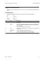
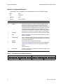
The registers are as described in the PCI CD/CDa User’s Guide except for the changes described
below.
Command Register
In this register, bit 2 is different from its implementation in the PCI CD/CDa firmware.
Size
8-bit
I/O
read-write
Address
0x00
Access
PCD_CMD
Bit
PCD_
Description
4–7
STAT_INT_EN
A value of one enables the corresponding STAT bit to cause an interrupt when
it is asserted.
3
ENABLE
Set to one to enable the PCD8 interface. This bit is set after the direction is
chosen and typically after the first DMA buffer is ready. To reset direction or
flags, toggle this bit.
To flush the DMA FIFOs, clear then set this bit.
2
INV
When set, inverts the bits in each byte, so that ones become zeroes and zeroes
become ones.
1
FORCEBNR
A value of 1indicates that the board is not ready.
0
DIR
A value of 1 indicates that data is coming in to the PCD8.
A value of 0 indicates that data is going out from the PCD8.
EDT, Inc. May 2007
10