1
AR-200_e.book 1 ページ 2003年7月14日 月曜日 午後1時11分 Owner’s Manual Before using this unit, carefully read the sections entitled: "USING THE UNIT SAFELY" and "IMPORTANT NOTES" ( p. 2, p. 3). These sections provide important information concerning the proper operation of the unit. Additionally, in order to feel assured that you have gained a good grasp of every feature provided by your new unit, Owner's manual should be read in its entirety. The manual should be saved and kept on hand as a convenient reference. Copyright 2000 ROLAND CORPORATION All rights reserved. No part of this publication may be reproduced in any form without the written permission of ROLAND CORPORATION. AR-200_e.book 2 ページ 2003年7月14日 月曜日 午後1時11分 USING THE UNIT SAFELY Used for instructions intended to alert the user to the risk of death or severe injury should the unit be used improperly. Used for instructions intended to alert the user to the risk of injury or material damage should the unit be used improperly. * Material damage refers other adverse effects respect to the home furnishings, as well animals or pets. to damage or caused with and all its to domestic • Before using this unit, make sure to read the instructions below, and the Owner’s Manual. .......................................................................................................... • Do not open (or modify in any way) the unit or its AC adaptor. .......................................................................................................... • Do not attempt to repair the unit, or replace parts within it (except when this manual provides specific instructions directing you to do so). Refer all servicing to your retailer, the nearest Roland Service Center, or an authorized Roland distributor, as listed on the "Information" page. .......................................................................................................... • Never use or store the unit in places that are: • Subject to temperature extremes (e.g., direct sunlight in an enclosed vehicle, near a heating duct, on top of heat-generating equipment); or are • Damp (e.g., baths, washrooms, on wet floors); or are • Humid; or are • Exposed to rain; or are • Dusty; or are • Subject to high levels of vibration. .......................................................................................................... • This unit should be used only with a rack or stand that is recommended by Roland. .......................................................................................................... The symbol alerts the user to important instructions or warnings.The specific meaning of the symbol is determined by the design contained within the triangle. In the case of the symbol at left, it is used for general cautions, warnings, or alerts to danger. The symbol alerts the user to items that must never be carried out (are forbidden). The specific thing that must not be done is indicated by the design contained within the circle. In the case of the symbol at left, it means that the unit must never be disassembled. The ● symbol alerts the user to things that must be carried out. The specific thing that must be done is indicated by the design contained within the circle. In the case of the symbol at left, it means that the powercord plug must be unplugged from the outlet. • When using the unit with a rack or stand recommended by Roland, the rack or stand must be carefully placed so it is level and sure to remain stable. If not using a rack or stand, you still need to make sure that any location you choose for placing the unit provides a level surface that will properly support the unit, and keep it from wobbling. .......................................................................................................... • Be sure to use only the AC adaptor supplied with the unit. Also, make sure the line voltage at the installation matches the input voltage specified on the AC adaptor’s body. Other AC adaptors may use a different polarity, or be designed for a different voltage, so their use could result in damage, malfunction, or electric shock. .......................................................................................................... • Do not excessively twist or bend the power cord, nor place heavy objects on it. Doing so can damage the cord, producing severed elements and short circuits. Damaged cords are fire and shock hazards! .......................................................................................................... • This unit, either alone or in combination with an amplifier and headphones or speakers, may be capable of producing sound levels that could cause permanent hearing loss. Do not operate for a long period of time at a high volume level, or at a level that is uncomfortable. If you experience any hearing loss or ringing in the ears, you should immediately stop using the unit, and consult an audiologist. .......................................................................................................... • Do not allow any objects (e.g., flammable material, coins, pins); or liquids of any kind (water, soft drinks, etc.) to penetrate the unit. .......................................................................................................... 2 AR-200_e.book 3 ページ 2003年7月14日 月曜日 午後1時11分 • Immediately turn the power off, remove the AC adaptor from the outlet, and request servicing by your retailer, the nearest Roland Service Center, or an authorized Roland distributor, as listed on the "Information" page when: • The AC adaptor or the power-supply cord has been damaged; or • Objects have fallen into, or liquid has been spilled onto the unit; or • The unit has been exposed to rain (or otherwise has become wet); or • The unit does not appear to operate normally or exhibits a marked change in performance. .......................................................................................................... • In households with small children, an adult should provide supervision until the child is capable of following all the rules essential for the safe operation of the unit. .......................................................................................................... • Protect the unit from strong impact. (Do not drop it!) .......................................................................................................... • Do not force the unit’s power-supply cord to share an outlet with an unreasonable number of other devices. Be especially careful when using extension cords—the total power used by all devices you have connected to the extension cord’s outlet must never exceed the power rating (watts/amperes) for the extension cord. Excessive loads can cause the insulation on the cord to heat up and eventually melt through. .......................................................................................................... • Before using the unit in a foreign country, consult with your retailer, the nearest Roland Service Center, or an authorized Roland distributor, as listed on the "Information" page. .......................................................................................................... • The unit and the AC adaptor should be located so their location or position does not interfere with their proper ventilation. .......................................................................................................... • Always grasp only the plug or the body of the AC adaptor when plugging into, or unplugging from, an outlet or this unit. .......................................................................................................... • Whenever the unit is to remain unused for an extended period of time, disconnect the AC adaptor. .......................................................................................................... • Try to prevent cords and cables from becoming entangled. Also, all cords and cables should be placed so they are out of the reach of children. .......................................................................................................... • Never climb on top of, nor place heavy objects on the unit. .......................................................................................................... • Never handle the AC adaptor body, or its plugs, with wet hands when plugging into, or unplugging from, an outlet or this unit. .......................................................................................................... • Before moving the unit, disconnect the AC adaptor and all cords coming from external devices. .......................................................................................................... • Before cleaning the unit, turn off the power and unplug the AC adaptor from the outlet (p. 10). .......................................................................................................... • Whenever you suspect the possibility of lightning in your area, disconnect the AC adaptor from the outlet. .......................................................................................................... 3 AR-200_e.book 4 ページ 2003年7月14日 月曜日 午後1時11分 IMPORTANT NOTES In addition to the items listed under “USING THE UNIT SAFELY” on page 2-3, please read and observe the following: Power Supply • Do not use this unit on the same power circuit with any device that will generate line noise (such as an electric motor or variable lighting system). • Use a cable from Roland to make the connection. If using some other make of connection cable, please note the following precautions. • Some connection cables contain resistors. Do not use cables that incorporate resistors for connecting to this unit. The use of such cables can cause the sound level to be extremely low, or impossible to hear. For information on cable specifications, contact the manufacturer of the cable. • The AC adaptor will begin to generate heat after long hours of consecutive use. This is normal, and is not a cause for concern. Before Using PC Cards • Before connecting this unit to other devices, turn off the power to all units. This will help prevent malfunctions and/or damage to speakers or other devices. • Never attempt to remove a PC Card from the drive while the drive is operating (the indicator is lit); damage could result to both the card and the drive. Placement • This device may interfere with radio and television reception. Do not use this device in the vicinity of such receivers. • To avoid possible breakdown, do not use the unit in a wet area, such as an area exposed to rain or other moisture. Maintenance • For everyday cleaning wipe the unit with a soft, dry cloth or one that has been slightly dampened with water. To remove stubborn dirt, use a cloth impregnated with a mild, non-abrasive detergent. Afterwards, be sure to wipe the unit thoroughly with a soft, dry cloth. • Remove any disk from the drive before powering up or down. • To avoid the risk of malfunction and/or damage, insert only PC Cards into the disk drive. Never insert any other type of disk. Avoid getting paper clips, coins, or any other foreign objects inside the drive. Before Using Cards Using DATA Cards • Carefully insert the PC card all the way in—until it is firmly in place. PC card • Never use benzine, thinners, alcohol or solvents of any kind, to avoid the possibility of discoloration and/or deformation. Additional Precautions • Unfortunately, it may be impossible to restore the contents of data that was stored DATA card once it has been lost. Roland Corporation assumes no liability concerning such loss of data. • Use a reasonable amount of care when using the unit’s buttons, sliders, or other controls; and when using its jacks and connectors. Rough handling can lead to malfunctions. • Never strike or apply strong pressure to the display. • When connecting / disconnecting all cables, grasp the connector itself—never pull on the cable. This way you will avoid causing shorts, or damage to the cable’s internal elements. • To avoid disturbing your neighbors, try to keep the unit’s volume at reasonable levels. You may prefer to use headphones, so you do not need to be concerned about those around you (especially when it is late at night). • When you need to transport the unit, package it in the box (including padding) that it came in, if possible. Otherwise, you will need to use equivalent packaging materials. 4 Eject button Copyright • Unauthorized recording, distribution, sale, lending, public performance, broadcasting, or the like, in whole or in part, of a work (musical composition, video, broadcast, public performance, or the like) whose copyright is held by a third party is prohibited by law. • Do not use this unit for purposes that could infringe on a copyright held by a third party. Roland assumes no responsibility whatsoever with regard to any infringements of third-party copyrights arising through your use of this unit. AR-200_e.book 5 ページ 2003年7月14日 月曜日 午後1時11分 Contents USING THE UNIT SAFELY ..............................................................................2 IMPORTANT NOTES ........................................................................................4 Main Features ..................................................................................................7 Panel Descriptions ..........................................................................................8 Important Notes on Making Connections and Switching the Power On and Off .......................9 Turning On the Power.................................................................................................................................................. 9 Installation......................................................................................................10 Attaching the Rubber Feet (Included Items) ........................................................................................................... 10 Rack Mounting (Important Notes on Heat Radiation).......................................................................................... 10 Attaching the Card Protector .................................................................................................................................... 11 Examples of Usage and Connection for the AR-200 ..................................12 Together with Other Equipment (System Examples) ............................................................................................ 12 Using the Control Input and Output Connectors...................................................................................... 12 Using the MIDI Connectors .......................................................................................................................... 13 What You Can Do (Usage Tips) ................................................................................................................................ 14 Repeat Playback of the Same Phrase ........................................................................................................... 14 Playing a Variety of Phrases in Succession................................................................................................. 14 Cards Handled by the AR-200 ......................................................................15 Types of Usable Cards................................................................................................................................................ 15 Card Storage Times and Number of Phrases.......................................................................................................... 15 Formatting a Card ....................................................................................................................................................... 15 Important Notes on Handling Cards ....................................................................................................................... 16 Card Compatibility with Other Models in the AR Series ..................................................................................... 17 Recording Audio............................................................................................18 Recording Units—Phrases............................................................................................................................. 18 Connecting External Devices ........................................................................................................................ 18 Procedure for Recording ............................................................................................................................................ 19 Required Settings for Recording Audio Signals (Recording Settings) ................................................... 19 Procedure......................................................................................................................................................... 22 Checking What You Recorded .................................................................................................................................. 23 Information Recorded on the Card .............................................................................................................. 23 Playback Using the Panel (Manual Playback).............................................24 Deleting Phrases ...........................................................................................25 Deleting Single Phrases ................................................................................................................................. 25 Deleting All Phrases....................................................................................................................................... 25 Recording and Playing MIDI Data (MIDI Phrase) ........................................26 What is a MIDI Phrase? ................................................................................................................................. 26 Connecting External Devices ........................................................................................................................ 26 Procedure for Recording MIDI Phrases ...................................................................................................... 26 Procedure for Playing Back MIDI Phrases.................................................................................................. 27 Controlling the AR-200 from an External Device (Control Input Connectors) .........................28 What Is No-voltage/Make-contact? ............................................................................................................ 28 Types of Control Input Playback ................................................................................................................. 28 Types of Control Input Recording ............................................................................................................... 28 Playback By Card Data............................................................................................................................................... 28 Cards Created on the AR-3000, AR-2000, or AR-1 .................................................................................... 28 Card made on the AR-100/200..................................................................................................................... 28 AR-200 Settings ............................................................................................................................................... 29 Playing Back Phrases Assigned to the Connectors (Direct Playback)................................................................. 30 5 AR-200_e.book 6 ページ 2003年7月14日 月曜日 午後1時11分 Contents Specifying Phrases in Binary Notation (Binary Playback) .................................................................................... 31 To Specify Phrases with Binary Signals ...................................................................................................... 32 Phrase Number / Binary Signal chart ......................................................................................................... 33 Repeated Playback of Phrases (Interval Playback) ................................................................................................ 34 Controlling Recording with the Control Connectors (Terminal Rec) ................................................................. 34 What is Terminal Rec/Use and Applications ............................................................................................ 34 Connecting Equipment .................................................................................................................................. 35 Operational Specifications for Terminal Rec .............................................................................................. 35 AR-200 Settings ............................................................................................................................................... 36 To Specify Phrases with Binary Signals ...................................................................................................... 37 Controlling Another Device with the AR-200 (Control Output Connectors) ...........................38 Starting Another Device (Busy Out)......................................................................................................................... 38 Controlling Another Device (Control Out) ............................................................................................................. 39 Applications Guide (For Use in Conjunction with the AR-3000) Controlling the AR-200 with MIDI Signals (MIDI control) ...........................42 What is MIDI Control?/What You Can Do Using MIDI Control ........................................................... 42 Playback of Phrases Using MIDI Signals................................................................................................................. 42 Connecting External Devices ........................................................................................................................ 42 Assignment of Phrases to Note Numbers (MIDI Note Map)................................................................... 43 AR-200 Settings ............................................................................................................................................... 44 Synchronized Recording and Playback with Multiple AR Units (AR-LINK) ............................45 Other Useful Functions During Phrase Playback.......................................47 Playing Data for Two Units on the Left and Right (Dual Mono Mode)................................................. 47 Line Out (Thru) Setting During Phrase Playback...................................................................................... 47 Adjusting the Sound Quality During Audio Phrase Playback (EQ–Equalizer).................................... 48 Appendices Troubleshooting ............................................................................................50 Error messages .............................................................................................52 Regarding Cards............................................................................................53 Card Audio Recording Time Chart .......................................................................................................................... 53 Recorded Phrase Data ................................................................................................................................................ 54 Settings When a Card Is Formatted.......................................................................................................................... 54 AR-3000 settings that can be used ............................................................................................................................ 55 MODE SW Settings ........................................................................................56 Control I/O Connector specifications ..........................................................57 MIDI Implementation .....................................................................................58 MIDI Implementation Chart ...........................................................................64 Specification ..................................................................................................66 Input/Output Standard........................................................................................................................... 68 Dimensions................................................................................................................................................ 68 Index ...............................................................................................................69 6 AR-200_e.book 7 ページ 2003年7月14日 月曜日 午後1時11分 Main Features High-quality Recording and Playback Thanks to Roland’s innovative RDAC system, you can enjoy high-quality, recording and playback using less data. You can select recording settings that suit the situation and the capacity of the card (sampling frequency: 6 levels, recording mode: 4 levels). This ensures support for recording and playback in a variety of situations and uses. What you record and the settings are all saved on the card, so you can change situations rapidly simply by changing cards. The AR-200 can record and play back up to a maximum of 250 phrases (using cards created on Roland’s AR-3000 allows playback of up to 1000 phrases). Audio Recording System with No Moving Parts An audio recording system that uses PC cards and has no moving parts is employed. The system has no rotating parts or drive mechanism, so it’s practically maintenance free. It provides excellent sound quality and superior reliability. A Variety of Control Jacks for a Wide Range of Playback Methods As connectors to use for control, the unit features a Control In jack, MIDI connectors, and AR-LINK connectors. This lets you select from a variety of playback methods and create systems matched to usage and situations. Compact Body for Easy Portability The compact half-rack size body takes little space, and can be conveniently transported. If a separately sold RAD-50 rack mount adaptor is used, the AR-200 can be installed in an EIA rack. MIDI Connectors Allow for Play of Musical Instruments and Syncing with Video Since the unit is equipped with MIDI connectors, you can record and play back MIDI signals. You can play an electronic musical instrument automatically, just like playing back an audio phrase. Control of recording/playback using MIDI signals is also supported. This means you can use MTC and MMC signals to obtain recording/playback that is synchronized to video and other external devices. Multi-track Operation–AR-LINK Feature The AR-LINK feature lets you link the unit to up to 31 other units to create a completely synchronized multi-track system. The AR-3000 is required as a master control device. Capable of DC-Powered Operation Since external DC power supply is also supported, a wide variety of applications are possible. 7 AR-200_e.book 8 ページ 2003年7月14日 月曜日 午後1時11分 Panel Descriptions fig.kakubu Front Panel Bottom Chassis Rear Panel Front panel 15. INPUT VOLUME 1. PHONES jack 16. Control input and DC input terminal (CONT A) 2. MIDI/CLIP indicator 3. SLAVE Indicator 4. Display 17. Control I/O connector (CONT B) 5. PLAY button * This is not an RS-232C type connector. 6. PLAY indicator 18. MIDI OUT/THRU connector 7. STOP button 8. Decrement ( 9. Increment ( ) button ) button 10. MEMORY FULL indicator 11. CARD slot 12. Eject button Rear panel 13. OUTPUT jacks 14. INPUT jacks 8 * The terminal/connector section features a protective cover. Whenever you remove this cover, such as when making connections to the connectors, make sure not to lose it. Additionally, keep the cover out of the reach of children. This is normally used as a MIDI OUT connector. However, by using a card with settings made on an AR-3000, this can also function as a MIDI THRU connector. 19. MIDI IN connector 20. AR-LINK Connectors (OUT and IN) 21. Power connector (for supplied AC adaptor) Bottom chassis 22. REC MODE switches 23. MODE switches AR-200_e.book 9 ページ 2003年7月14日 月曜日 午後1時11分 Important Notes on Making Connections and Switching the Power On and Off • To prevent malfunction and/or damage to speakers or other devices, always turn down the volume, and turn off the power on all devices before making any connections. • Once the connections have been completed, turn on power to your various devices in the order specified. By turning on devices in the wrong order, you risk causing malfunction and/or damage to speakers and other devices. (When turning the power off, reverse this procedure.) Connected device → AR-200 → Power amp, etc. • This unit is equipped with a protection circuit. A brief interval (a few seconds) after power up is required before the unit will operate normally. • To avoid risk of electric shock, do not touch the connectors while the unit is in operation. • Never remove a card during recording of phrases. Furthermore, do not turn off the power or remove the AC adaptor cord during recording of phrases. Doing so may damage the card. • To avoid the risk of malfunction and/or damage, insert only PC Card into the disk drive. Never insert any other type of disk. Avoid getting paper clips, coins, or any other foreign objects inside the drive. • The pin assignment for the connectors is as shown below. Before making any connections, make sure that this pin assignment is compatible with that of all your other devices. GND(SLEEVE) HOT(TIP) GND(SLEEVE) HOT(TIP) COLD(RING) With balanced output With unbalanced output Turning On the Power The AR-200 is not equipped with a power switch. Power is turned on when electricity is supplied to the power connector (for the supplied AC adaptor), or to the control input and DC input, or control I/O connectors’ DC IN (p. 8). Supplied AC adaptor: ACI-100C (sold separately) Control input and DC input/control I/O connector specifications Voltage: 9 to 24 V DC Current: 900 mA * Refer also to "DC power supply" (p. 57). Do not supply electrical power simultaneously to multiple connectors or terminals; doing so may result in damage to the unit. 9 AR-200_e.book 10 ページ 2003年7月14日 月曜日 午後1時11分 Installation Attaching the Rubber Feet (Included Items) Attach these as required, such as when you’re using the AR-200 without mounting it on a rack or the like. Peel off the double-sided tape from the rubber feet and affix the rubber feet at the locations shown in the following figure. fig.set-01 Bottom Chassis Rack Mounting (Important Notes on Heat Radiation) When you are mounting the unit on a rack or the like, give attention to the following points to ensure efficient cooling. • Install in a well-ventilated location. • Avoid mounting in a sealed rack. Warm air within the rack cannot escape and is sucked into the unit again, making efficient cooling impossible. • When you are using a stacked mounting arrangement, be especially sure to provide for adequate ventilation within the rack to keep discharged air from being sucked back into the unit. If the back surface of the rack cannot be kept open, then provide a ventilation port or ventilation fan at the upper area of the back surface of the rack, where warm air accumulates. • When you are using the unit in a portable case or rack, remove the covers from the front and back surfaces of the case, so that the front and back surfaces of the unit are not obstructed. • If an error message informing you of a dangerous rise in temperature appears (p. 52), then heat-dissipating measures are needed. Refer to the cautions just described and check the installed state of the unit and the rack. * When placing the unit on the rack, be careful not to pinch your fingers. * For more information about installation, also see "Placement" in the Usage Notes (p. 4). 10 AR-200_e.book 11 ページ 2003年7月14日 月曜日 午後1時11分 Installation Rack-Mounting the AR-200 By attaching a rack mount adaptor to the AR-200 (RAD-50: sold separately) you can install it in an EIA rack. One RAD-50 can accommodate up to two AR-200 units. 1 Remove the four rubber feet from bottom of the unit. fig.set-02 Note: Do not use these holes. 2 Attach the RAD-50 adaptor to the AR-200 using the screws that are supplied with the RAD-50. fig.set-03 RAD-50 Attaching the Card Protector By attaching the Card Protector (supplied) to the AR-200, you can prevent the PC card from inadvertently being removed from the AR-200. After confirming that the card is securely inserted in the card slot, use the provided screws to attach the Card Protector, as shown in the figure below. fig.set-04 Card Protector 11 AR-200_e.book 12 ページ 2003年7月14日 月曜日 午後1時11分 Examples of Usage and Connection for the AR-200 You can use the AR-200 alone or in combination with other AR-200 units or other equipment to play audio in a wide variety of scenes. This section shows some examples of these. You can use these examples as a starting point for making changes to match your own usage circumstances. Together with Other Equipment (System Examples) Using the Control Input and Output Connectors • Control Input: Messages, explanations, warnings, announcements, effect sounds, and the like are played with high sound quality according to control signals from sensors, buttons, and switches. "Controlling the AR-200 from an External Device (Control Input Connectors)" (p. 28) fig.use-01 Sensor Program Timer Momentary Switch pm. Pressing the switch plays back a set announcement, guidance message, explanation, or the like •Set announcements played back as required •Broadcast of museum exhibition explanations or guidance Sensor-triggered automatic broadcasts Control timer for automatic broadcasts •Guidance announcements made upon detection of a person's presence •Playback of event performances at attractions and other sites •Playback of message broadcasts and announcements at regular, set times in offices, factories, or other such areas •Broadcasts at set times of upcoming events at amusements areas Types of External Control Power Amp Control Signal Audio Signal • Control Output: Control signals can be output during or after phrase playback to control an external device. "Controlling Another Device with the AR-200 (Control Output Connectors)" (p. 38) fig.use-02 Busy Out Control Signal Audio Signal Power Amp Only during phrase playback, power amp or other gear is powered up (offset time set to five seconds) Lamp lights during phrase playback Power Unit Power Reray Switch Control Out After playback ends, controls external device * A card formatted on the AR-2000 or AR-3000 is required. Power Amp •Extinguishing lights •When elevator doors are closed and other similar situations 12 AR-200_e.book 13 ページ 2003年7月14日 月曜日 午後1時11分 Examples of Usage and Connection for the AR-200 Using the MIDI Connectors • Spatial Expression Using MIDI signals from a master AR-3000 (sold separately), you can play back background music performances from sound generating modules and other devices as well as sound effects phrases on slave AR-200s. This lets you create sonic fields with six-channel multi-playback. "Controlling the AR-200 with MIDI Signals (MIDI control)" (p. 42) fig.use-03 (As a MIDI Sequencer) MIDI Patcher MIDI Signal Audio Signal Sound Module Power Amp Power Amp Power Amp • Sound-field Control Using batch MIDI control from a switch box, you can change programs on a mixer, equalizer, or the like to control the sonic field. fig.use-04 ( As a MIDI Sequencer) Switch Box Digital Mixer & Console Control Signal MIDI Signal Audio Signal MIDI Patcher Equalizer Power Amp Equalizer Power Amp 13 AR-200_e.book 14 ページ 2003年7月14日 月曜日 午後1時11分 Examples of Usage and Connection for the AR-200 What You Can Do (Usage Tips) Repeat Playback of the Same Phrase There are several methods for doing this. Choose a playback method that matches your usage conditions. "Interval Playback" (p. 34) Changing Playback Mode Settings to Interval Mode You can have phrases be played back repeatedly at set intervals. Inputting a Continuous Make-contact Signal to the Control Input Connectors You can repeat playback by continuously shorting the control input connectors. * With some settings, playback doesn’t repeat even when you continuously input a make-contact signal. For information, refer to "Controlling the AR-200 from an External Device (Control Input Connectors)" (p. 30). Playing a Variety of Phrases in Succession There are several methods for doing this. Choose a playback method that matches your usage conditions. Using Direct Playback of Control Input By inputting control signals to a connector number from 1 through 9, you can play back the phrase assigned to the number. "Direct Playback" (p. 30) Using Binary Playback of Control Input You can select phrases by inputting binary signals to connector numbers 1 through 8, and play the selected phrases in succession each time you input control signals to the START connector. 14 "Binary Playback" (p. 31) AR-200_e.book 15 ページ 2003年7月14日 月曜日 午後1時11分 Cards Handled by the AR-200 Types of Usable Cards The AR-200 stores recorded audio and MIDI signals on the card. Additionally, all information other than recorded audio (phrase information) is stored on the card as well. (That is, it is not stored in the AR unit itself.) This means that you can change the settings simply by swapping cards. For cards used with the AR-200, we recommend Roland’s line of optional PC cards (PM Series): PM-004 (4M bytes) PM-008 (8M bytes) PM-016 (16M bytes) PM-024 (24M bytes) PM-032 (32M bytes) PM-040 (40M bytes) PM-080 (80M bytes) PM-096 (96M bytes) PM-184 (184M bytes) PM-256 (256M bytes) PM-01G (1G bytes) You can also use a Smart Media adaptor (the optional SMA-1). → This adaptor allows commercially available Smart Media cards to be used with the AR-200. Depending on the type of PC card or SmartMedia you are using, it may not be possible to perform recording or playback at the set RDAC-Grade and RDAC-Mode due to data write speed and other factors. * SmartMedia is a trademark of Toshiba Corporation. Card Storage Times and Number of Phrases A maximum of 250 phrases may be created on cards formatted on the AR-200. * The available recording time for a single card varies according to card capacity and recording settings. * For a rough guide to maximum recording times with various settings, see the "Card Audio Recording Time Chart" in the reference materials (p. 53). Formatting a Card When you use a new card or a card used previously on a device other than the unit, you must first format (initialize) the card. * Cards formatted on the AR-3000 can be used just as they are. * Please refer to p. 18 for information regarding previous models (AR-2000/100/1). Depending on the length of stored phrases, it may not be possible to create the set maximum number of phrases. The time required for formatting a card varies with the card type (capacity), but may last from several seconds up to ten or twenty seconds. 15 Basic Editing Operations Roland PC Cards (PM series) Information cannot be stored in memory in the AR unit itself, so be sure to purchase cards separately. There are several types of card capacities available. The amount of information that you can store differs according to card capacity. AR-200_e.book 16 ページ 2003年7月14日 月曜日 午後1時11分 Cards Handled by the AR-200 Notes Regarding Formatting Performing formatting erases all data on the card. Before you format the card, make sure it contains no data you don’t want to lose. * A maximum of 250 phrases may be created on cards formatted on the AR-200. * The available recording time for a single card varies according to card capacity and recording settings. * For a rough guide to maximum recording times with various settings, see the "Card Audio Recording Time Chart" in the reference materials (p. 53). Depending on the length of stored phrases, it may not be possible to create the set maximum number of phrases. Procedure for Formatting Cards 1 Confirm that there is no card inserted in the card slot. 2 Hold down the STOP button for at least 5 seconds A flashing “Fot” appears. fig.card-01 3 Insert the card that you wish to format into card slot. 4 Press the PLAY button, formatting will begin. 5 If you wish to stop the process, press the STOP button. When formatting is completed, the message is changed in the display. fig.card-02 Important Notes on Handling Cards • When Inserting Insert the card all the way into the card slot. • When Removing To remove the card, press the eject button. Never remove a card during recording, playback, or formatting. Furthermore, do not turn off the power or remove the AC adaptor cord during recording, playback, or formatting. Doing so may damage the card. 16 Never remove a card while formatting is in progress. AR-200_e.book 17 ページ 2003年7月14日 月曜日 午後1時11分 Cards Handled by the AR-200 Card Compatibility with Other Models in the AR Series If You’re Using a Legacy Model In case the card you are using with the AR-200 has been used on one of Roland’s previous AR-2000, AR-100, or AR-1 devices; or if using an AR-200 card on one of these legacy models, the operational specifications are shown below. Basic Editing Operations • When using a card formatted on the AR-2000 (compatible models: AR2000/100/1) with the AR-200. You can carry out recording and playback without having to make any special changes. Although playback may be carried out as is, the card cannot be used for recording. fig.card-06 Recording, PLAY Formatted on AR-2000 • When using a card formatted on the AR-200 with a legacy model (AR2000/100/1) Cards formatted on the AR-200 cannot be used with these previous models. fig.card-07 You must perform Card Convert and Phrase Convert on the AR-3000 in order to make the card formatted on the AR-200 to be usable with a legacy model (AR-2000/100/1). 17 AR-200_e.book 18 ページ 2003年7月14日 月曜日 午後1時11分 Recording Audio Recording Units—Phrases A single item of data recorded from the point where you start recording until the point where you stop recording is called a phrase. Audio data and MIDI data are both handled as phrases. Phrases are managed by phrase numbers. "What is a MIDI Phrase?" (P.26) fig.rec-01 Phrase Number Connecting External Devices The AR-200 features analog input jacks (INPUT) on the rear panel.Refer to the following figure when connecting the AR-200 with external devices. fig.rec-02 Headphone Powered Speakers For monitor Formatted Card IN (ANALOG) AC Adaptor OUT (ANALOG) Sound Recording Device Monitor Output During Recording and Recording Standby Sounds input from the analog input jack (INPUT) can be output from the audio output jacks (BALANCED OUTPUT) during recording, recording standby, and ordinary playback. * The quality of sounds output from the audio output jack differs from that of RDACGrade or RDAC-Mode sound quality. Be sure to play back the phrase after recording to confirm the quality of the content. 18 "Important Notes on Making Connections and Switching the Power On and Off" (P.9) AR-200_e.book 19 ページ 2003年7月14日 月曜日 午後1時11分 Recording Audio Procedure for Recording To enable recording with the AR-200 using cards formatted on the AR-2000, carry out the "Formatting a Card" (P.15) procedure. Required Settings for Recording Audio Signals (Recording Settings) Basic Editing Operations In order perform recording matched to usage conditions, including the connected equipment, recording source, sound quality, time, and playback system, you make recording settings. Recording settings are made in phrase units. You can mix phrases having different recording settings on a single card. The possible recording time of a card varies according to the recording settings. For a rough guide to maximum recording times with various settings, see the "Recording Audio" (P.18) in the reference materials (p. 53). RDAC-Grade(sampling frequency) (REC MODE SW–3) The RDAC grade is the type of sampling frequency for digital recording. On the AR-200, you can select from among six grades. fig.rec-03 S-HIGH : 48 kHz HIGH : 44.1 kHz STANDARD : 32 kHz LONG1 : 22.05 kHz LONG2 : 16 kHz ANNOUNCE : Sound quality Amount of card memory consumed High Large 8 kHz Small STANDARD is best for ordinary recording. ANNOUNCE uses up the least card space, and is best for recording announcements, narration, and the like. When you are recording audio such as a narration with ANNOUNCE or LONG2, you can record with higher clarity by using the equalizer to cut the bass range. Select an RDAC grade that matches the circumstances of use. Procedure 1 2 Turn off the power of the AR-200. Set the SW 1-3 REC MODE switches on the AR-200’s bottom panel. 19 AR-200_e.book 20 ページ 2003年7月14日 月曜日 午後1時11分 Recording Audio The different grade settings are shown in the following table. SW 1 SW 2 SW 3 ANNOUNCE ON OFF OFF LONG2 OFF ON OFF LONG1 OFF OFF OFF STANDARD ON ON OFF HIGH OFF OFF ON S-HIGH ON OFF ON RDAC-Grade 3 If the type of card does not provide the recording time you want, change the RDAC mode or RDAC grade setting to use less card capacity, then perform recording again. Turn on the power of the AR-200. * Use a narrow-tipped object to set the MODE switches to ON or OFF. RDAC-Mode (Signal Processing Format)(REC MODE SW 4, 5) The RDAC mode is a type of digital data processing system for recording. On the AR-200, you can select from among four modes. fig.rec-04 LINEAR : 16 bit PCM Recording MODE3 : About 2.5 times the recording time of Linear. MODE2 : More than 2.5 times the recording time of Linear. MODE1 : About 4 times the recording time of Linear. Sound quality Amount of card memory consumed High Large Small LINEAR enables recording at the highest sound quality, but uses the most space on the card. MODE1 uses up the least card space, and is suited to long recording times. Select an RDAC mode that matches the circumstances of use. Procedure 1 2 Turn off the power of the AR-200. Set the SW 4 and 5 REC MODE switches on the AR-200’s bottom panel. The different grade settings are shown in the following table. SW 4 SW 5 MODE 1 OFF OFF MODE 2 ON OFF MODE 3 OFF ON LINEAR ON ON RDAC-Mode 3 Turn on the power of the AR-200. * Use a narrow-tipped object to set the MODE switches to ON or OFF. 20 "Card Audio Recording Time Chart" (P.53) AR-200_e.book 21 ページ 2003年7月14日 月曜日 午後1時11分 Recording Audio What’s RDAC? RDAC (Roland Digital Audio Coding) is a proprietary audio recording standard from Roland. It achieves high sound quality and also makes it possible to record for long times. If You’re Not Sure About Which Grade and Mode to Choose Basic Editing Operations The optimal grade and mode vary according to the usage conditions, including the connected equipment, recording source, sound quality, time, and playback system. The factory default settings are RDAC-Grade: LONG1; and RDAC-Mode: MODE1. First, try recording and playback with these settings. In most cases, this yields satisfactory sound quality. Recording Type (Stereo/Mono)(REC MODE SW 6) Select either stereo recording or mono recording. Choosing mono recording gives you recording times that are twice as long as with stereo recording. Procedure 1. Turn off the power of the AR-200. 2. Set the SW 6 REC MODE switch on the AR-200’s bottom panel. OFF : MONO ON : STEREO 3. Turn on the power of the AR-200. * Use a narrow-tipped object to set the MODE switches to ON or OFF. What is mono recording In the case of mono recording, input the audio signal to the "MONO/L" input jack. When audio signals are input simultaneously to the "MONO/L" and "R" input jacks, L and R are mixed and recorded. Line Thru Output REC SW6: OFF (mono) When audio signals are input to "MONO/L," output is from OUTPUT L and R. When audio signals are input to "R," output is from OUTPUT R only. When audio signals are input to both "MONO/L" and "R," solely the signals input to "MONO/L" are output from OUTPUT L, while the "MONO/L" and "R" signals are mixed and output from OUTPUT R. REC SW6: ON (stereo) Audio signals input to "MONO/L" are output from OUTPUT L, and audio signals input to "R" are output from OUTPUT R. 21 AR-200_e.book 22 ページ 2003年7月14日 月曜日 午後1時11分 Recording Audio Procedure Make the correct connections, then turn on the power switch. 1 2 Insert a formatted card into one of the slots. Press the [ ] or [ to be recorded. ] button to select the number of the phrase The non-recording phrase number in display is flashed. fig.rec-05 * If you are re-recording over a previously recorded phrase, you should delete the phrase. (p. 26) * You cannot change the phrase number after recording, so be sure to select the phrase number you want to record. 3 Hold down the STOP button and press the PLAY button to go into recording standby. The PLAY indicator is flashed while the recording standby mode. 4 Input the sounds from the device connected to the input jacks, then use the input volume knob to adjust the recording level so that the MIDI/CLIP indicator does not light. Nominal Input level:0 dBm Maximum input level: +2.5 dBu * If signals louder than +2.5 dBu are being input, rotate the input volume knob to the left of center. * Press the STOP button and recording standby mode will end. 22 "Important Notes on Making Connections and Switching the Power On and Off" (P.9) AR-200_e.book 23 ページ 2003年7月14日 月曜日 午後1時11分 Recording Audio 5 When you press the PLAY button, sounds are input to the input jacks, and recording begins. * Even when the PLAY button is pressed, recording does not begin until the sound is at or above the base level (-36 dBu) (in trigger recording standby). While recording is in progress, the PLAY indicator lights, and a dot flashes in the display. fig.rec-06 6 Press the Stop button to end recording. fig.rec-07 Checking What You Recorded After recording ends, you can play back the phrase by pressing the Play button. Information Recorded on the Card The AR-200 stores recorded audio and MIDI signals on the card. Additionally, all settings data (such as MIDI channels and other information) is stored on the card (the information is not stored in the AR unit itself). This means that you can change the settings simply by swapping cards. 23 Basic Editing Operations * When the card becomes full, recording will stop automatically. The MEMORY FULL indicator tells how much recording time is left. The MEMORY FULL indicator light flashes when the recorded data reaches 90% of the card’s capacity, then stays on when 100% capacity is reached. AR-200_e.book 24 ページ 2003年7月14日 月曜日 午後1時11分 Playback Using the Panel (Manual Playback) Here is how to playback the phrase to check the recording. The sound will be output from the Phones jack and from the output jacks. fig.man-01 Procedure 1 2 Insert a card containing recorded information into a slot. Press the [ ] or [ ] button to select the number of the phrase to be played back. * The non-recording phrase number in display is flashed. 3 Press the PLAY button and the phrase will playback. During playback of the phrase, the Play indicator lights up.The dot in the display also lights up. fig.man-02 lit Dot lit up * Pressing the Stop button ends playback. 24 AR-200_e.book 25 ページ 2003年7月14日 月曜日 午後1時11分 Deleting Phrases You can delete unneeded phrases, either by deleting single phrase units or entire collections of phrases. Deleting Single Phrases 1 ] button to select the number of the phrase Basic Editing Operations 2 Press the [ ] or [ to be deleted. You cannot delete phrases on cards formatted on the AR-2000. Attempting to enter the menu screen causes the error message “Er16” to appear in the display. Hold down the STOP button for at least 5 seconds. A flashing “dEL” appears. fig.del-02 3 Press the PLAY button to execute deletion of the phrase. * To stop the procedure, press the STOP button. Never remove a card while phrases are being deleted. When you’re finished deleting the phrase, the display indication changes. fig.del-03 Deleting All Phrases 1 After confirming that the card to be deleted is inserted in the card slot, hold down the STOP button for at least five seconds. A flashing “dEL” appears. 2 Press the [ ] button, so you have the “ALL” displayed. fig.del-04 3 Press the PLAY button to execute deletion of the phrases. * To stop the procedure, press the STOP button. When you’re finished deleting the phrase, the display indication changes. fig.del-03 25 AR-200_e.book 26 ページ 2003年7月14日 月曜日 午後1時11分 Recording and Playing MIDI Data (MIDI Phrase) What is a MIDI Phrase? You can use the AR-200 for recording and playback of MIDI data. MIDI data recorded with the AR-200 are called “MIDI phrases.” This automatically changes to MIDI THRU during recording and in recording standby. MIDI phrases and audio phrases are treated identically as phrases. "Important Notes on Making Connections and Switching the Power On and Off"(P.9) You can take MIDI data recorded with a MIDI sequencer and record this to the AR-200 as MIDI phrases, using them as “MIDI data playback sent to sound generating modules for broadcast within buildings.” Procedure for Recording MIDI Phrases MIDI data is saved by the AR-200 as Format 0 SMFs (Standard MIDI Files). The MIDI Time Base is fixed at 192. * Audio phrases and MIDI phrases cannot be recorded or played back simultaneously. * The capacity of cards used for MIDI phrases is affected not only by recording time, but by the size of the MIDI data in the MIDI phrases themselves. Please be aware that when you record MIDI phrases, the possible recording time for a single card varies according to the size of the MIDI data. Control of the unit by using MIDI signals is described in another chapter. Please refer to "Controlling the AR-200 with MIDI Signals (MIDI control)"(P.42). Connecting External Devices fig.mid-01 Make the correct connections, then turn on the power switch. "Important Notes on Making Connections and Switching the Power On and Off"(P.9) 1. Insert a formatted card into one of the slots. 2. Press the [ ] or [ ] button to select the number of the phrase to be recorded. * The non-recording phrase number in display is flashed. * If you are re-recording over a previously recorded phrase, you should delete the phrase (p. 25). * You cannot change the phrase number after recording, so be sure to select the phrase number you want to record. 3. Hold down the STOP button and press the PLAY button to go into recording standby. The PLAY indicator is flashed while the recording standby mode. fig.mid-02 blink MIDI IN MIDI OUT MIDI OUT 4. Hold down the [ ] button for at least five seconds to switch to MIDI mode. The MIDI/CLIP indicator is lit. MIDI Sequencer * Recording will begin when a System Real time message “Start” (FAH) is received from the connected MIDI device. 5. After you press the PLAY button, recording begins when MIDI signals are input from the connected MIDI device. MIDI IN While recording is in progress, the PLAY indicator lights, and a dot flashes in the display. MIDI Sound Source Powerd Speaker (For Monitor) fig.mid-03 lit * When the card becomes full, recording will stop automatically. 26 AR-200_e.book 27 ページ 2003年7月14日 月曜日 午後1時11分 Recording and Playing MIDI Data (MIDI Phrase) fig.mid-04 The MEMORY FULL indicator tells how much recording time is left. The MEMORY FULL indicator light flashes when the recorded data reaches 90% of the card’s capacity, then stays on when 100% capacity is reached. 6. Press the Stop button to end recording. * Recording will also stop if a Stop signal is received from the connected MIDI device. Procedure for Playing Back MIDI Phrases Manual playback 1. Insert a card containing recorded information into a slot. 2. Press the / button to select the number of the phrase to be played back. The MIDI/CLIP indicator lights up when a MIDI phrase is selected. fig.mid-05 lit • Some MIDI sequencers output MIDI sound generator setup messages (tone settings for each part, volume information, effects data, and so on) when a song is selected, and this may prevent MIDI messages from being recorded correctly when recording with the AR200 begins. In such instances, start recording with the AR-200 first, then after this select and play back the song from the MIDI sequencer. Playback Using Control Input and Other Input • In recording MIDI with the AR-200, the recording tempo is set at 120 (tempo information is not stored). You can play back control input and other input in the same manner as you would with audio phrases. * The non-recording phrase number in display is flashed. 3. Press the PLAY button and the phrase will playback. While playback is in progress, the PLAY indicator lights, and a dot flashes in the display. 4. Press the Stop button to end playback. Using MIDI Signals to Start and Stop Recording With the AR-200, you can do things such as have recording start upon reception of a start message from another MIDI device, as well as have a recording in progress be stopped upon reception of a stop message. During recording standby, recording starts when a System Real time start message (FAH) is received, and stops when a stop message (FCH) is received. Furthermore, start (FAH) and stop (FCH) messages are transmitted when phrases are played back. "MIDI Implementation", "MIDI Implementation"(p. 58-p. 64) 27 Applications • You cannot change the phrase number afterward, so be sure select the phrase number you want to record before you start recording. AR-200_e.book 28 ページ 2003年7月14日 月曜日 午後1時11分 Controlling the AR-200 from an External Device (Control Input Connectors) You can use the control input and DC input screw terminals (CONT A) and the 25-pin D-sub-type control I/O connector (CONT B) on the AR-200’s rear panel to control the AR-200 from an external device. This chapter explains how to connect external devices and make the settings for the AR-200. What Is No-voltage/Makecontact? This is contact that makes starting possible simply by connecting two lines to the control input connectors and shorting their ends. This is a general-use method that lets you create start systems easily using only a switch and without any need for a power source, enabling easy use for a variety of applications. You can control playback and recording with the AR-200 using On/Off signals from No-voltage/Make-contact input from an external source. Operational Specifications for Control Input Playback fig.inp-01 When new control signals are input during playback of a phrase When control signals are input continuously A phrase in progress is stopped, and playback of another specified Direct Playback phrase is begun only when the (Nomal) control signal being input is of a higher priority than that of the phrase currently being played back Repeated Direct Playback Playback stopped, followed by (Reverse Priority) playback of the specified phrase Repeated Playback stopped, followed by Interval Playback playback of the specified phrase Repeated Binary Playback Repeated Disabled Types of Control Input Recording The AR-200 features one type of control input recording, "Terminal Rec "(p. 34). By connecting infrared sensors or switches, relays, and timers, or other external starting connectors to the AR-200, you can use the unit in an even wider variety of applications. Playback By Card Data The AR-200 can help simplify installation operations by making the starting-side contact hot and sharing the ground as the common connector. Cards Created on the AR-3000, AR-2000, or AR-1 For more on the control input specifications, refer to "Control I/O Connector specifications" (p. 57) in the Appendices. Important Note on Using the Control I/O Connector The control I/O connector cannot be used to switch the power to the AR unit on or off. Playback will use the settings (playback method) recorded in the card. For more information, please refer to the owner’s manuals for each device. * Some functions are not available. (p. 55) Card made on the AR-100/200 Playback mode is available Direct Playback(Normal). Phrases 1 through 9 are assigned to the control I/O connector Port Nos. 1 through 9. Direct playback(Normal playback) 2 3 4 5 Port No. 1 Phrase 0001 0002 0003 0004 0005 28 A Control Signal A Control Signal A Control Signal * You cannot use more than one type of playback at the same time. fig.inp-02 A Control Signal There are four types of control input playback: Playback by Card Data (p. 28), Direct Playback (Reverse Priority) (p. 30), Binary Playback (p. 31), and Interval Playback (p. 34). A Control Signal Types of Control Input Playback A Control Signal When making connections to the ports, be careful not to lose the removed screws. Place the screws out of the reach of small children. If a screw is accidentally swallowed, immediately consult a physician. A phrase is played back when a control signal is input directly to the terminal with the number to which the phrase is assigned. Up to 9 phrases can be played back.Assign Phrases 1 through 9 beforehand to Port Nos. 1 through 9, respectively. This makes it very convenient when you want to specify a desired phrase directly using a switch, relay, sensor, or other such means. 9 0009 AR-200_e.book 29 ページ 2003年7月14日 月曜日 午後1時11分 Controlling the AR-200 from an External Device (Control Input Connectors) Connectors Used for Direct Play (Control I/O Connector) “1–9”: Inputting a control signal directly to the terminal with the number corresponding to the phrase starts playback of the phrase. fig.inp-06 Port NO. 1 Port NO. 2 0002 “10 (Stop)”: This stops phrase playback. In addition to the connectors just described, shorting “11/12 (GND)” (ground) connectors enables “On.” fig.inp-03 Select a Phrase STOP 10 9 1 0001 AUDIO OUTPUT 0002 Interrupted * If a control signal has a lower priority than that of the phrase currently being played back, the specified phrase is not played back. Playback is repeated while the control signal is continuously input. fig.inp-07 Port NO. 1 0001 0001 0001 AUDIO OUTPUT 12 11 GND AR-200 Settings "Important Notes on Making Connections and Switching the Power On and Off" (p. 9) fig.inp-04 Port NO. 1 Port NO. 2 STOP Port 0002 0001 AUDIO OUTPUT 0001 Interrupted Playback: Set the MODE switches on the AR-200’s bottom panel to select “PLAYBACK BY CARD DATA” from the control input modes (PLAYBACK BY CARD DATA/DIRECT PLAYBACK/BINARY PLAYBACK/INTERVAL PLAYBACK). * You cannot achieve control input playback merely by connecting a device to the port. Be sure to set the control input mode and match the method used for connecting to the connectors. Procedure for Setting the Control Input Mode 1. Turn off the power of the AR-200. Input a control signal to a Port, 1–9. → The phrase assigned to the Port is played back. stopping: Input a control signal to Port 10 (STOP). → Playback of the phrase is stopped. Order of Priority The control input pins have a priority order. 2. Set the MODE switches on the AR-200’s bottom panel as shown below. SW1: OFF SW2: OFF 3. Turn on the power of the AR-200. * Use a pointed object to change the ON/OFF settings of the MODE switches. The priority order is as follows: fig.inp-05 Assigning Phrases to the Terminals HIGH LOW 0001 > 0002 > 0003 ........> 0009 When a new high-priority control signal is input during phrase playback, playback of the current phrase is stopped, and playback of the specified phrase begins. Assign phrases 1 through 9 to Port Nos. 1 through 9. Settings in Effect When a Card Is Formatted fig.inp-13 Port No. 1 2 3 4 5 9 Phrase 0001 0002 0003 0004 0005 0009 29 Applications Basic Operation of Direct Playback (Normal Playback) Selecting the Control Input Mode AR-200_e.book 30 ページ 2003年7月14日 月曜日 午後1時11分 Controlling the AR-200 from an External Device (Control Input Connectors) Playing Back Phrases Assigned to the Connectors (Direct Playback) What Is Direct Playback (Reverse Priority)?/Use and Applications By inputting control signals directly to Port Nos. 1 through 9, you can play back the phrases assigned to those numbers. Up to 9 phrases can be played back. Assign phrases 1 through 9 beforehand to Port Nos. 1 through 9. This is very convenient when you want to specify a desired phrase directly using a switch, relay, sensor, or other such means. Operational Specifications for Direct Playback (Last-In) Basic Operation of Direct Playback (Reverse Priority) fig.inp-10 Port No. 1 Port No. 2 STOP Port AUDIO OUTPUT 0002 0001 0001 Interrupted Playback: Input control signals to Port Nos. 1 through 9. A Control Signal A Control Signal A Control Signal A Control Signal A Control Signal A Control Signal fig.inp-08 → This plays the phrase assigned to the connector. stopping: Input control signals to Port No. 10 (STOP). 9 2 3 4 5 Port No. 1 Phrase 0001 0002 0003 0004 0005 → This stops playback of the phrase. 0009 Connecting External Devices Connectors Used for Direct Play (Last-In) (Control I/O Connector) 1 through 9: Inputting a control signal directly to the connector with the number corresponding to the phrase starts playback of the phrase. “10 (STOP) “: Stop phrase playback. In addition to the connectors just described, shorting the “11/12 (GND)” (ground) connectors enables “On.” "Operational Specifications for Control Input Playback" (p. 28) Priority Order The most recently input control signal is given priority in playback. If a new and different control signal is input during playback of a phrase, playback of the current phrase is stopped, and playback of the specified phrase then begins. fig.inp-11 Port No. 1 fig.inp-09 Port NO.2 STOP 10 9 Select a Phrase 1 AUDIO OUTPUT 0001 0002 0001 Interrupt Playback is repeated while the control signal is continuously input. 12 11 GND fig.inp-12 Port No.1 0001 AUDIO OUTPUT "Important Notes on Making Connections and Switching the Power On and Off" (p. 9) 30 0001 0001 AR-200_e.book 31 ページ 2003年7月14日 月曜日 午後1時11分 Controlling the AR-200 from an External Device (Control Input Connectors) AR-200 Settings fig.inp-14 Binary Specification Port No.1--8 87654321 Selecting the Control Input Mode Set the MODE switches on the AR-200’s bottom panel to select “DIRECT PLAYBACK” from the control input modes (PLAYBACK BY CARD DATA/DIRECT PLAYBACK/ BINARY PLAYBACK/INTERVAL PLAYBACK). You cannot achieve control input playback merely by connecting a device to the port. Be sure to set the control input mode and match the method used for connecting to the connectors. Procedure for Setting the Control Input Mode 1. Turn off the power of the AR-200. 2. Set the MODE switches on the AR-200’s bottom panel as shown below. 01110000 START SIGNAL Phrase 112 PLAY * To conduct Binary Playback, you will need to obtain a control device capable of generating binary signals. * Input of binary specifications should be completed in no more than 50 milliseconds. Connecting External Devices Connectors Used in Binary Playback “1–8”: Phrases are specified in binary format using combinations of 0 (Off) and 1 (On). “9 (START) “: Start phrase playback. “10 (STOP) “: Stop phrase playback. SW2: OFF In addition to the connectors just described, shorting the 11/ 12 (GND) (Ground) connectors enables “On.” 3. Turn on the power of the AR-200. fig.inp-15 * Use a pointed object to change the ON/OFF settings of the MODE switches. START Select a Phrase STOP 10 9 8 1 Assigning Phrases to the Terminals Assign phrases 1 through 9 to Port Nos. 1 through 9. Settings in Effect When a Card Is Formatted 12 11 fig.inp-13 Port No. 1 2 3 4 5 9 Phrase 0001 0002 0003 0004 0005 0009 Specifying Phrases in Binary Notation (Binary Playback) What Is Binary Playback?/Use and Applications By inputting binary (Base 2) signals to Port Nos. 1 through 8 to select a phrase and inputting a start message to the START terminal, you can then play back the selected phrase. A maximum of 250 phrases can be selected and played back with this method. This allows you to specify 250 phrases with control signals (from a switch or other ON/OFF signal device), without having to use computers or other complicated equipment. GND "Important Notes on Making Connections and Switching the Power On and Off" (p. 9) Even without connecting to all eight connectors used for making the binary specifications, you can still conduct Binary Playback. The number of phrases that can be specified is determined by the formula “two to the nth power minus one” (with “n” being the number of connectors used). Example: Using three timers or other such devices capable of outputting the necessary signals gives two to the third power minus one (i.e., 8 - 1 = 7), meaning you can specify the seven phrases 001 through 007. However, start signals feature other special requirements. 31 Applications SW1: ON AR-200_e.book 32 ページ 2003年7月14日 月曜日 午後1時11分 Controlling the AR-200 from an External Device (Control Input Connectors) Operational Specifications of Binary Playback Procedure for Setting the Control Input Mode Basic Operation of Binary Playback 2. Set the MODE switches on the AR-200’s bottom panel as shown below. fig.inp-16 Binary Specification Port No.1--8 1. Turn off the power of the AR-200. SW1: OFF 0001 SW2: ON 3. Turn on the power of the AR-200. START Port * Use a pointed object to change the ON/OFF settings of the MODE switches. 0001 AUDIO OUTPUT Playback: Specify the phrases using combinations of 0 (Off) and 1 (On) signals to Port Nos. 1 through 8, and Port Nos. 11 and 12, and input a control signal to the Port No. 9 (START). To Specify Phrases with Binary Signals → This plays back the specified phrase. Example: Specifying Phrase 0112 (Phrase #: 0112) Stopping: 1. Convert the phrase number to a binary signal number. Input a control signal to Port No. 10 (STOP). ”0” (Off) → This stops playback of the phrase. ”1” (On) The basic operation of Binary Playback is shown below. fig.inp-17 Binary Specification Port No.1--8 0001 0002 0003 Phrase Number/Binary Signal Correspondence Table (p. 36) Disabled START Port The phrase number “0012” becomes the binary signal “01110000.” With the above step, Phrase No. 0112 is converted to: AUDIO OUTPUT 0001 0001 0002 0003 Binary specified phrases are played back repeatedly. Playback is repeated while the start signal is continuously input. fig.inp-18 Port No. INPUT Signal 8 7 6 5 4 3 2 1 0 1 1 1 0 0 0 0 Phrase Number (Binary) You can begin playback of phrases by specifying phrases in binary with the start signal continuously being input. When the START connector control signal switches to Off, the current phrase finishes, and then playback is stopped. No action results when a new start signal is input while a phrase is being played back. AR-200 Settings Selecting the Control Input Mode Set the MODE switches on the AR-200’s bottom panel to select “BINARY PLAYBACK” from the control input modes (PLAYBACK BY CARD DATA/DIRECT PLAYBACK/ BINARY PLAYBACK/INTERVAL PLAYBACK). * You cannot achieve control input playback merely by connecting a device to the port. Be sure to set the control input mode and match the method used for connecting to the connectors. 32 Input of binary specifications should be completed in no more than 50 milliseconds. AR-200_e.book 33 ページ 2003年7月14日 月曜日 午後1時11分 Controlling the AR-200 from an External Device (Control Input Connectors) Phrase Number / Binary Signal chart Phrase No. 001 002 003 004 005 006 007 008 009 010 011 012 013 014 015 016 017 018 019 020 021 022 023 024 025 026 027 028 029 030 031 032 033 034 035 036 037 038 039 040 041 042 043 044 045 046 047 048 049 050 Binary (Port 87654321) 00000001 00000010 00000011 00000100 00000101 00000110 00000111 00001000 00001001 00001010 00001011 00001100 00001101 00001110 00001111 00010000 00010001 00010010 00010011 00010100 00010101 00010110 00010111 00011000 00011001 00011010 00011011 00011100 00011101 00011110 00011111 00100000 00100001 00100010 00100011 00100100 00100101 00100110 00100111 00101000 00101001 00101010 00101011 00101100 00101101 00101110 00101111 00110000 00110001 00110010 Phrase No. 051 052 053 054 055 056 057 058 059 060 061 062 063 064 065 066 067 068 069 070 071 072 073 074 075 076 077 078 079 080 081 082 083 084 085 086 087 088 089 090 091 092 093 094 095 096 097 098 099 100 Binary (Port 87654321) 00110011 00110100 00110101 00110110 00110111 00111000 00111001 00111010 00111011 00111100 00111101 00111110 00111111 01000000 01000001 01000010 01000011 01000100 01000101 01000110 01000111 01001000 01001001 01001010 01001011 01001100 01001101 01001110 01001111 01010000 01010001 01010010 01010011 01010100 01010101 01010110 01010111 01011000 01011001 01011010 01011011 01011100 01011101 01011110 01011111 01100000 01100001 01100010 01100011 01100100 Phrase No. 101 102 103 104 105 106 107 108 109 110 111 112 113 114 115 116 117 118 119 120 121 122 123 124 125 126 127 128 129 130 131 132 133 134 135 136 137 138 139 140 141 142 143 144 145 146 147 148 149 150 Binary (Port 87654321) 01100101 01100110 01100111 01101000 01101001 01101010 01101011 01101100 01101101 01101110 01101111 01110000 01110001 01110010 01110011 01110100 01110101 01110110 01110111 01111000 01111001 01111010 01111011 01111100 01111101 01111110 01111111 10000000 10000001 10000010 10000011 10000100 10000101 10000110 10000111 10001000 10001001 10001010 10001011 10001100 10001101 10001110 10001111 10010000 10010001 10010010 10010011 10010100 10010101 10010110 Phrase No. 151 152 153 154 155 156 157 158 159 160 161 162 163 164 165 166 167 168 169 170 171 172 173 174 175 176 177 178 179 180 181 182 183 184 185 186 187 188 189 190 191 192 193 194 195 196 197 198 199 200 Binary (Port 87654321) 10010111 10011000 10011001 10011010 10011011 10011100 10011101 10011110 10011111 10100000 10100001 10100010 10100011 10100100 10100101 10100110 10100111 10101000 10101001 10101010 10101011 10101100 10101101 10101110 10101111 10110000 10110001 10110010 10110011 10110100 10110101 10110110 10110111 10111000 10111001 10111010 10111011 10111100 10111101 10111110 10111111 11000000 11000001 11000010 11000011 11000100 11000101 11000110 11000111 11001000 Phrase No. 201 202 203 204 205 206 207 208 209 210 211 212 213 214 215 216 217 218 219 220 221 222 223 224 225 226 227 228 229 230 231 232 233 234 235 236 237 238 239 240 241 242 243 244 245 246 247 248 249 250 Binary (Port 87654321) 11001001 11001010 11001011 11001100 11001101 11001110 11001111 11010000 11010001 11010010 11010011 11010100 11010101 11010110 11010111 11011000 11011001 11011010 11011011 11011100 11011101 11011110 11011111 11100000 11100001 11100010 11100011 11100100 11100101 11100110 11100111 11101000 11101001 11101010 11101011 11101100 11101101 11101110 11101111 11110000 11110001 11110010 11110011 11110100 11110101 11110110 11110111 11111000 11111001 11111010 33 AR-200_e.book 34 ページ 2003年7月14日 月曜日 午後1時11分 Controlling the AR-200 from an External Device (Control Input Connectors) Repeated Playback of Phrases (Interval Playback) modes (PLAYBACK BY CARD DATA/DIRECT PLAYBACK/BINARY PLAYBACK/INTERVAL PLAYBACK). The specified phrase will be played back at fixed intervals. Make each of the terminal settings beforehand for the playback interval and phrases to be played back. You cannot achieve control input playback merely by connecting a device to the port. Be sure to set the control input mode and match the method used for connecting to the connectors. When making settings in Interval Playback mode, assign Phrases 1 through 9 to the control output connectors 1 through 9. The playback interval settings are shown below. Port No. 1 second 2 5 seconds 3 10 seconds 4 15 seconds 5 30 seconds 6 1 minute 7 5 minutes 8 15 minutes 9 30 minutes SW1: ON SW2: ON 3. Turn on the power of the AR-200. * Use a pointed object to change the ON/OFF settings of the MODE switches. Operational Specifications of Interval Playback Basic Operation of Interval Playback fig.inp-21 Port No. 2 STOP Port 0002 1. Turn off the power of the AR-200. 2. Set the MODE switches on the AR-200’s bottom panel as shown below. Playback Interval 1 Procedure for Setting the Control Input Mode 0002 AUDIO OUTPUT 0002 interrupted Interval time used for phrases [Interval time used for phrases] Controlling Recording with the Control Connectors (Terminal Rec) What is Terminal Rec/Use and Applications You can specify phrases by inputting binary (base 2) signals to the Port Nos. 1 through 8, and perform record, playback, and erase functions by inputting control signals to Port Nos. 9 and 10. A total of 250 phrases can be specified with control signals (On/Off). This is convenient when you want to control recording from an external control device. fig.inp-22 Binary Specification Port 1--8 Playback: 87654321 01110000 Input control signals to the control Input/output connectors No. 1 through 9. → Results in the repeated play of the phrase assigned to the terminal. stopping: Input a control signal to Port No. 10 (STOP). Signal sent to Port Nos. 9 and 10 Phrase112 Record Play Delete [Signal sent to Port Nos. 9 and 10] → This stops playback of the phrase. * To conduct binary control, you need to provide a control device that can generate binary signals. AR-200 Settings * Input of binary specifications should be completed in no more than 50 milliseconds. Selecting the Control Input Mode Set the MODE switches on the AR-200’s bottom panel to select “INTERVAL PLAYBACK” from the control input 34 AR-200_e.book 35 ページ 2003年7月14日 月曜日 午後1時11分 Controlling the AR-200 from an External Device (Control Input Connectors) Connecting Equipment Recording 9: 0 (Off) Connectors Used in Terminal Rec 10: 1 (On) 1–8: Phrases are specified in binary format using combinations of 0 (Off) and 1 (On). → While control signals are being input, the specified phrase 9, 10: Combinations of 0 (Off) and 1 (On) are used to specify record, erase, and playback. is recorded. When input of the control signal stops, recording then ends. fig.inp-25 15–18 (CONT OUT): Outputs signals for confirming the presence or absence of phrases. In addition to the connectors just described, shorting Ports 11 and 12 (Ground) enables “On.” Timing Chart (Rec) Tbrs Tbrh Binary Specification Port No.1--8 Trw fig.inp-23 Rec /Play /Delete Select a Phrase 10 9 8 Port No.10 Tbrd Tbred 1 Busy Out Tvred Tvrd AUDIO OUTPUT 12 11 18 GND 15 CONT OUT Operational Specifications for Terminal Rec Phrases are specified by combinations of signals of 0 (Off) and 1 (On) to the Port Nos. 1 through 8 as well as Port Nos. 11 and 12, and record, playback, and erase functions are specified with combinations of control signals of 0 (Off) and 1 (On) to Port Nos. 9 and 10. Presence or Absence of Phrases : Play Pulse Width : Binary Setup Time : Binary Hold Time : Busy Delay Time : Audio Delay Time : End Busy Delay Time : End Audio Delay Time min max 300 200 100 - 300 300 100 100 (msec) * Recording does not start if there is a binary-specified phrase that has already been recorded (the recording instruction is disabled). When recording, either specify an empty phrase or delete the existing phrase before recording the new one. Additionally, in Terminal Rec, since a make signal is output from the CONT OUT connector when a specified phrase has already been recorded, this allows confirmation using a connected external control device. * When headphones are being used, no Busy Out signal is output. * When you're using the Terminal Recording Mode, recording If there is a binary-specified phrase that has already been recorded, a signal is output from the CONT OUT connector (Port No. 15). If there is an empty phrase, no signal is output. takes place immediately, without entering trigger recording standby. * During Terminal Rec, the CONT OUT connector functions as a connector for signals confirming the presence or absence of phrases. Note that this differs from the normal function of CONT OUT. fig.inp-24 Timing Chart (The presence or absence of phrases) Binary Specification Port No.1--8 Tbcd Control Out (the presence or absence of phrases) min Tbcd : Binary Phrase Output Delay Times - max 250 (msec) 35 Applications "Important Notes on Making Connections and Switching the Power On and Off" (p. 9) Trw Tbrs Tbrh Tbrd Tvrd Tbred Tvred AR-200_e.book 36 ページ 2003年7月14日 月曜日 午後1時11分 Controlling the AR-200 from an External Device (Control Input Connectors) Playback Erase 9: 1 (On) 9: 1 (On) 10: 0 (Off) 10: 1 (On) → The specified phrase is played back. Even when control → First, when ON is input to Port No. 9, and then ON is signals are input continuously, the phrase is played back input to Port No. 10, erasure of the specified phrase one time only and then ends. begins. Erasure ends when the signal from the CONT- fig.inp-26 OUT connector confirming the presence or absence of Timing Chart (PLAY) Tbps Binary Specification Port No.1--8 the phrase changes to OFF. Tbph * Erasure does not begin if the binary-specified phrase is empty (the erase instruction is disabled). When erasing, specify a phrase that has already been recorded. Tpw Port No.9 fig.inp-27 Tbpd Timing Chart ( Delete) Tbds Busy Out Tpdd Tvpd Tvbd Binary Specification Port No.1--8 AUDIO OUTPUT Tpw Tbps Tbph Tbpd Tvpd Tvbd : Play Pulse Width : Binary Setup Time : Binary Hold Time : Busy Delay Time : Audio Delay Time : End Busy Delay Time min max 20 200 100 - 300 300 100 (msec) Port No.9 Trdw Tpds Tpdh Tprd Port No.10 Tbcd Tbdh Control Out (the presence or absence of phrases) * Playback does not begin if the binary-specified phrase is empty (the playback instruction is disabled). When playing back, specify a phrase that has already been recorded. min Trdw Tpds Tpdh Tprd Tbds Tbdh Tbcd Tpdd max : Delete Rec Pulse Width : Delete Play Setup Time : Delete Play Hold Time : Delete Play Rec Delay Time : Delete Binary Setup Time : Delete Binary Hold Time : Binary Phrase Output Delay Time : Play Phrase Output Delay Time 100 50 50 0 200 20 250 - *2500(typ.) (msec) *Play phrase output delay time is dependent on the card used. * When headphones are being used, no Busy Out signal is output. AR-200 Settings Switching the Terminal Recording Mode Set the MODE switches on the AR-200’s bottom panel to select the Terminal Rec (BINARY REC) mode. You cannot achieve control input playback merely by connecting a device to the port. Be sure to set the control input mode and match the method used for connecting to the connectors. Procedure for Setting the Control Input Mode 1. Turn off the power of the AR-200. 2. Set the MODE switches on the AR-200’s bottom panel as shown below. SW6: ON 3. Turn on the power of the AR-200. * Use a pointed object to change the ON/OFF settings of the MODE switches. 36 AR-200_e.book 37 ページ 2003年7月14日 月曜日 午後1時11分 Controlling the AR-200 from an External Device (Control Input Connectors) To Specify Phrases with Binary Signals Note that the way phrases are specified in Terminal Rec differs from that used in Binary Playback. Example: Binary specification of Phrase 112 (Phrase #: 112) Convert the phrase number to a binary signal number. ”0” (Off) ”1: (On) The phrase number “0001” is specified in the binary notation as “00000000,” and as shown in the Phrase Number/Binary Signal Correspondence Table below, each subsequent specification is shifted by one. 001 00000000 87654321 Port No. 00000001 00000010 00000011 00000100 00000101 00000110 00000111 248 249 250 11111000 11111001 11111010 Applications 001 002 003 004 005 006 007 Phrase No. "Phrase Number / Binary Signal chart" (p. 37) The phrase number “112” becomes the binary signal “01101111.” Input of binary specifications should be completed in no more than 50 milliseconds. 37 AR-200_e.book 38 ページ 2003年7月14日 月曜日 午後1時11分 Controlling Another Device with the AR-200 (Control Output Connectors) You can use the screw-type control input and DC input terminals (CONT A) and the 25-pin D-sub-type control I/O connector (CONT B) on the AR-200’s rear panel to control an external device from the AR-200. Starting Another Device (Busy Out) The AR-200 outputs two kinds of control signals, Busy Out and Control Out. What is the Busy Out Signal?/ Connecting Devices This chapter explains how to connect external devices and make the settings for the AR-200. For examples describing the use of the control input and DC input terminals and the control I/O connector, refer to the "Examples of Usage and Connection for the AR-200" (p. 12). For more on the control input specifications, refer to "Control I/O Connector specifications" (p. 57) in the Appendices. Important Note on Using the Control Input and Output Ports Busy Out is a continuous signal output from the BUSY OUT connector during playback (as well as during recording and recording standby) of audio phrases, MIDI phrases, pattern phrases, and song phrases. This signal can be used to start amplifiers and other external devices in sync with phrase playback. The Busy Out specifications are no-voltage/make-contact, with a make-contact time of 1 second and a contact capacity of a maximum of DC 30 V at 3 A. Port Nos. 13 and 17 have Make-contact during output. fig.out-01 13 9 1 When making connections to the ports, be careful not to lose the removed screws. Place the screws out of the reach of small children. If a screw is accidentally swallowed, immediately consult a physician. 17 13 Normal 17 13 During Output 17 "Important Notes on Making Connections and Switching the Power On and Off" (p. 9) Output of Busy Out Signals In Dual Mono Mode (p. 47) When in Dual Mono mode, the Busy Out signal of the left channel is output from the BUSY OUT connector, and the right channel Busy Out signal is output from the CONT OUT connector. Dual Mono Mode (p. 47) fig.out-02 During Interval Repeat During Delay Time AUDIO OUTPUT BUSY OUT ON : ON : ON MAKE START 38 During playing a Phrase CLOSE (ON) OPEN (OFF) MAKE END AR-200_e.book 39 ページ 2003年7月14日 月曜日 午後1時11分 Controlling Another Device with the AR-200 (Control Output Connectors) Controlling Another Device (Control Out) What is the Control Out Signal?/ Connecting Devices The Control Out signal is output for a duration of one second from the CONT OUT connector after playback of audio phrases, MIDI phrases, pattern phrases, and song phrases. This signal can be used to start amplifiers and other external devices in sync with phrase playback. You can set the time that is to pass after phrase playback before output is made to anything from 0 seconds to 59 minutes 59 seconds. Settings are made in phrase units. The Control Out specifications are no-voltage/make-contact, with a make-contact time of 1 second and a contact capacity of a maximum of DC 30 V at 3 A. Applications Port Nos. 15 and 18 have Make-contact during output. Note that if playback of a phrase in progress is cut off, no Control Out signal is output. fig.out-03 9 1 18 18 15 18 15 During Output Normal 15 "Important Notes on Making Connections and Switching the Power On and Off" (p. 9) Output of Control Out Signals In Dual Mono Mode (p. 47) Note that Control Out signals are not output in Dual Mono Mode (the Control Out settings are not effective). In such instances, if the Busy Out output settings have been made, then the Busy Out signal of the left channel is output from the BUSY OUT connector, and right channel’s Busy Out signal is output from the CONT OUT connector. AR-200 Settings * Settings for these parameters cannot be made with the AR200. Only phrases set on the AR-3000 are effective. For detailed information, please refer to the AR-3000 user’s manual. 39 AR-200_e.book 40 ページ 2003年7月14日 月曜日 午後1時11分 MEMO 40 AR-200_e.book 41 ページ 2003年7月14日 月曜日 午後1時11分 Applications Guide (For Use in Conjunction with the AR-3000) 41 AR-200_e.book 42 ページ 2003年7月14日 月曜日 午後1時11分 Controlling the AR-200 with MIDI Signals (MIDI control) What is MIDI Control?/What You Can Do Using MIDI Control MIDI is an acronym for “Musical Instrument Digital Interface,” and is a standard by which electronic musical Instruments and computers can exchange musical data. You can connect any device conforming to the MIDI standard with a MIDI cable, and then transmit performance data and control the device’s operation and settings. • You can record and play back MIDI signals from an external MIDI device in the same manner as with audio phrases. • You can use MIDI signals from an external MIDI device as control signals for controlling playback of audio and MIDI phrases. • You can use received MMC signals to start and stop recording and playback of audio phrases. Moreover, by using an optional AR-3000 to create and edit phrases, the following is also possible. For detailed information, please refer to the AR-3000 user’s manual. • You can use MMC and MTC signals from an external MIDI device for remote control and synchronized operation. Refer to the "MIDI Implementation" (p. 64) for easy confirmation of the MIDI messages that can be sent and received by the AR-200 along with the more detailed MIDI specifications in "MIDI Implementation" (p. 58). Playback of Phrases Using MIDI Signals MIDI signals from an external MIDI device can be used as control signals in order to play back audio and MIDI phrases. Phrase playback can be controlled by the different types of MIDI messages, including Note On/Off, Note On Velocity, Panpot, and Expression. * MIDI phrases cannot be played back simultaneously with audio phrases or other MIDI phrases. Connecting External Devices When Playing Back Audio Phrases Using MIDI Signals fig.midi-01 (As a MIDI Sequencer) What is MMC (MIDI Machine Control)? MMC refers to MIDI messages that were devised in accord with certain agreements as to how to facilitate the centralized control of a multiple number of recording devices using one device. In addition to playback, stopping, and fast forwarding of songs, you can also select tracks for recording and carry out other operations merely by operating the one device which functions as the master. Use of MMC signals requires that the other devices be capable of remote operation using MMC signals. MIDI Sequencer MIDI OUT MIDI IN The AR-200 can work as a remote device, starting and stopping recording and playback of audio phrases when MMC signals are received. However, there is no connection between MMC master (operating device = sending side) and slave (receiving side) and MTC synchronization master and slave. What is MTC (MIDI time code)? MTC consists of MIDI messages that were devised to allow MIDI devices to synchronize correctly with professional-use tape recorders, video equipment, and the like. It differs from MIDI Clock, displaying the absolute time. The master device transmits the current absolute time (in hours/minutes/ seconds/frames from the start), and the time of the slave device is advanced to conform with it. Use of MMC signals requires that the other device is capable of synchronization using MTC. 42 Power Amp AR-200_e.book 43 ページ 2003年7月14日 月曜日 午後1時11分 Controlling the AR-200 with MIDI Signals (MIDI control) When Playing Back MIDI Phrases Using MIDI Signals MIDI Note Map (Phrase Assignments from Program Changes and Note Numbers) fig.midi-02 fig.midi-04 (As a MIDI Sequencer) MIDI OUT Program Change MIDI Sequencer MIDI IN MIDI OUT Note No. Phrase No. You can assign 128 phrases however you like 1 C-1 – G9 21 22 23 24 25 26 27 28 29 30 C-1 – D#7 C-1 – D#7 C-1 – D#7 C-1 – D#7 C-1 – D#7 C-1 – D#7 C-1 – D#7 C-1 – D#7 C-1 – D#7 C-1 – D#7 A0001 – A0100 A0101 – A0200 A0201 – A0300 A0301 – A0400 A0401 – A0500 A0501 – A0600 A0601 – A0700 A0701 – A0800 A0801 – A0900 A0901 – A1000 2 3 4 5 6 C-1 – D#7 C-1 – D#7 C-1 – D#7 C-1 – D#7 C-1 – D#7 A0001 – A0100 A0101 – A0200 A0201 – A0300 A0301 – A0400 A0401 – A0500 Power Amp MIDI IN Sound Source C-1 – G9 128 The phrase being played back is stopped. < Program Change1> C-1 C0 C1 C2 C3 C4 C5 C6 C7 C8 C9 G9 12 12 12 12 12 12 12 12 12 12 8 128 phrase all Applications guide Assignment of Phrases to Note Numbers (MIDI Note Map) When a Note On message is sent, the phrase corresponding to the note number is played back. You can specify all phrases by using a Program Change. Settings in Effect When a Card Is Formatted C-1 C0 C1 C2 C3 C4 C5 C6 C7 D#7 12 12 12 12 12 12 12 12 4 100 Phrase all fig.midi-03 Program Change 1 Note No. C-1 C#-1 D-1 : G9 < Program Change 21–30, 71–80, 2–11> Phrase A0001 A0002 A0003 : A0128 * By transmitting program change 128, you can then send a Note On message for a note number to interrupt a currently playing phrase. 43 AR-200_e.book 44 ページ 2003年7月14日 月曜日 午後1時11分 Controlling the AR-200 with MIDI Signals (MIDI control) AR-200 Settings MIDI Receive channel Settings (MIDI channel) This sets the MIDI receive channel. MIDI allows you to independently control two or more devices over a single MIDI cable. For example, when the MIDI channel for the sending device is set to “1,” then unless the MIDI channel of the receiving device (here, the AR-200) is also set to “1,” the MIDI message is not transmitted. Off : MIDI messages will not playback phrases. 1-16: Only the MIDI messages on the selected channel are received and played back. All : MIDI messages of any channel will playback phrases. With cards formatted on the AR-2000, you can check the MIDI reception channel settings, but they cannot be changed. Procedure for Making the MIDI Receive Channel Settings 1. While holding down the PLAY button, insert the card into the card slot. The MIDI indicator will blink, and the display will indicate the receive channel. 2. Press the [ ]/[ ] dial to select the MIDI Receive channel (OFF/1-16/ALL). 3. Press the PLAY button to set the specified MIDI receive channel. The MIDI indicator lights, and the phrase number is displayed. • If you press the STOP button, the MIDI receive channel setting will be canceled. MIDI Control Signals That Can Be Received (Receive Messages) If you use a card whose settings have been made on the AR3000, the following MIDI message can be received by the AR200. Note On Velocity: Volume level when playback of the phrase starts Panpot (CC10): Changes the positioning of the sound in the left and right channels Expression (CC11): Changes the master volume For more a detailed explanation of MIDI, refer to "MIDI Implementation" and "MIDI Implementation Chart" (p. 58p. 64). MIDI Note Out Moreover, by using an optional AR-3000 to create and edit phrases, the following function are also possible. For detailed information, please refer to the AR-3000 user’s manual. If MIDI Note Out is set to “ON,” then when an audio phrase is played back, the MIDI Note Number On/Off signals set in "MIDI Note Map" (p. 43) are output from the MIDI OUT connector. In this case, if two or more note numbers have been assigned to that playback phrase, only the lowest note number will be transmitted. The MIDI signals are output through the channel set through the MIDI Receive channel. If the MIDI Receive channel is set to : “OFF”: “1-16”: There is no output Only the MIDI signals in the selected channel are input and output “ALL”: Output is through Channel 1 * If you are using Note messages to control two or more AR-200 units, set the MIDI Note Trigger setting of the slave AR-200 units to “Trig.””Trigger” is selected when the card is formatted. However, this setting cannot be changed on the AR-200. * Even when playing back MIDI phrases, Note Number On/Off signals are not output. 44 AR-200_e.book 45 ページ 2003年7月14日 月曜日 午後1時11分 Synchronized Recording and Playback with Multiple AR Units (AR-LINK) What is AR-LINK?/What You Can Do Using AR-LINK The AR-LINK connector is a transmission connector used for creating completely synchronized recording and playback with multiple AR-3000/200 devices. The connectors feature special leads for commands and master clock, allowing synchronization with sampling frequency precision. With one AR-3000 as the master, you can then link up to 31 other AR-3000s and/or AR-200s (for a total of 32 devices) to get 64-channel multitrack recording and playback. However, this system allows recording and playback only of audio phrases (MIDI phrases cannot be handled). * Synchronization with the AR-LINK is not available when only AR-200s are used. Important Notes on Making Connections and Switching the Power On and Off (p. 9) Use MIDI to send signals from an imaging device to the master AR-3000. You can chain 31 slave AR-200s to synchronize images and phrases. fig.link-02 MIDI SIGNAL AUDIO SIGNAL Image Device MMC MODE : MASTER MTC SYNC SOURCE : INTERNAL MTC SYNC OUT : MTC Synchronized Audio Phrase Playback with AR-LINK Signals Example of Connecting to an External Device Use MIDI to send a hard disk recorder’s operation data to the master AR-3000. Connecting four slave AR-200s in a chain then allows you to get 10-channel multitrack recording. MIDI OUT MTC, MMC SIGNAL Power Amp AR-3000 MIDI IN AR-LINK MASTER MMC MODE : SLAVE MTC SYNC SOURCE : MTC fig.link-01 AR-200 MIDI SIGNAL AUDIO SIGNAL AR-LINK SLAVE Hard Disk Player AUDIO PATCH BAY MTC, MMC SIGNAL AR-3000 MIDI IN Up to 31 AR-3000/200s (for a total of 32) can be linked. LINE IN AR-LINK MASTER LINE IN Applications Guide MIDI OUT AR-LINK SLAVE AR-200 AR-LINK SLAVE Important Notes on Making Connections and Switching the Power On and Off (p. 9) LINE IN LINE IN AR-LINK SLAVE 45 AR-200_e.book 46 ページ 2003年7月14日 月曜日 午後1時11分 Synchronized Recording and Playback with Multiple AR Units (AR-LINK) AR-200 Settings Selecting the AR-200’s Operation (ARLINK SLAVE) Set the AR-2000 so as to enable synchronization with ARLINK. The AR-200 can only be set to AR-LINK slave. Settings Procedure 1. Turn off the power of the AR-200. 2. Set the MODE switches on the AR-200’s bottom panel as shown below. SW4: ON 3. Turn on the power of the AR-200. The SLAVE indicator on the front panel lights up. * Use a pointed object to change the ON/OFF settings of the MODE switches. * For more detailed information about synchronized operation with AR-LINK, refer to the AR-3000 Owner’s Manual. 46 AR-200_e.book 47 ページ 2003年7月14日 月曜日 午後1時11分 Other Useful Functions During Phrase Playback Moreover, by using an optional AR-3000 to create and edit phrases, you can also use the following functions. For detailed information, please refer to the AR-3000 user’s manual. Line Out (Thru) Setting During Phrase Playback You can take audio from Line In, mix it during phrase playback, and mixed it from Line Out (or Line Thru). fig.etc-01 Playing Data for Two Units on the Left and Right (Dual Mono Mode) CD player or other sound playback device The Dual Mono mode is a feature for playing different mono audio phrases independently on the left and right channels. By outputting odd-numbered phrases (0001, 0003, ...) from the left channel and even-numbered phrases (0002, 0004, ...) from the right channel, you can play back two units’ worth of phrases using only the one device. You can also play back separate phrases on the left and right channels either simultaneously, or shifted. fig.mono-01 LINE IN BALANCED OUTPUT Sound input to line input + AR sound phrase Power Amp Even-Numbered Phrase 0001 0003 0005 0002 0004 0006 R . . . Odd-Numbered Phrase . . . L have been made on the AR-3000. For detailed information, please refer to the AR-3000 user’s manual. To Users of the AR-2000/100 (Legacy Models) You can also make the Line In sound fade out or in. Line throughput is possible only for signals connected to the Line In jacks. On the AR-2000/100 (legacy models), this “Dual Mono Mode” is the function called “Channel Playback Mode.” When using them, please try to keep in mind that the two functions are identical. 47 Applications Guide * You cannot make settings for this parameter on the AR-200. Furthermore, it is effective only with phrases whose settings This is useful when you want to do things like taking music from Line In and layering it with narration phrases as background music. AR-200_e.book 48 ページ 2003年7月14日 月曜日 午後1時11分 Other Useful Functions During Phrase Playback Line Thru Output Specifications The following output specifications apply, depending on the Line Thru settings. fig.etc-02 AR PHRASE OUTPUT During Phrase Playback During Phrase Playback When On When On (0%) When On (50%) When On (100%) Sound input to line input LINE THRU When fade-out or fade-in settings have been made AR PHRASE OUTPUT During Phrase Playback During Phrase Playback When On (0%) LINE THRU Fade-Out (TIME) Fade-In (TIME) Adjusting the Sound Quality During Audio Phrase Playback (EQ–Equalizer) You can adjust the quality of the sound during audio phrase playback with two-band equalization. 48 AR-200_e.book 49 ページ 2003年7月14日 月曜日 午後1時11分 Appendices 49 AR-200_e.book 50 ページ 2003年7月14日 月曜日 午後1時11分 Troubleshooting About recording Recording does not start • In trigger recording, recording starts automatically when the audio input is of a higher level than the trigger level (lever for starting recording). Adjust the input level so that recording is allowed to start. → " Trigger recording standby." (p. 23) About playback Control Input Playback (Direct/Binary) does not work as intended • Make sure the MODE switches’ settings (Direct/Binary) are selected correctly. You cannot achieve control input playback merely by connecting a device to the port. Be sure to set the control input mode and match the method used for connecting to the connectors. → "MODE SW Settings" (p. 56) Phrases in Direct Playback cannot be selected as intended • When the card is formatted, phrase assignments for Port Nos. 1 through 9 are such that Phrase 0001 is assigned to Port No. 1, Phrase 0002 to Port No. 1, and so on up to Phrase 0001, which is assigned to Port No. 9. Check to make sure that the phrases are properly selected. Phrases play repeatedly in Direct Playback • Check to make sure that “INTERVAL PLAYBACK” is not selected with the MODE switch settings. → "MODE SW Settings" (p. 56) The AR-LINK function does not work as intended • In the AR-LINK settings, is “AR-LINK Mode” set to “Off?” When using AR-LINK, set this to “Slave” to match your usage conditions. In addition, check the device connections (OUT, IN) for the AR-LINK connector. 50 About playback and recording of MIDI phrases MIDI phrases cannot be recorded correctly • Some MIDI sequencers output MIDI sound generator setup messages (tone settings for each part, volume information, effects data, etc.) when a song is selected, and this may prevent MIDI messages from being recorded correctly when recording with the AR-200 begins. In such instances, start recording with the AR200 first, then after this select and play back the song from the MIDI sequencer. MIDI data cannot be recorded • When recording MIDI data, switch to MIDI Recording mode. →"Recording and Playing MIDI Data (MIDI Phrase)" (p. 26) MIDI phrases are not played back • Is the MIDI Receive channel set to “Off?” → "MIDI Receive channel Settings (MIDI channel)" (p. 44) About MIDI Control Playback Phrases cannot be played back as intended in MIDI Control Playback • When a card is formatted, Program Change 1 is set to C1: 0001-G9:0128. Program Changes 21-30 have Phrases 0001-1000 assigned to them. Phrases 001-500 are assigned to Program Changes 21-30 for compatibility with the AR-2000. Confirm that the phrase you want to play back is correctly specified. * By transmitting program change 128, you can then send a Note On message for a note number to interrupt a currently playing phrase. AR-200_e.book 51 ページ 2003年7月14日 月曜日 午後1時11分 Troubleshooting Others AR-3000 to confirm whether or not the composite phrase has been saved. No sound • Reconfirm that the power to the AR-200 or connected device is on. • Reconfirm that the volume control on the AR-200 or connected device is turned up. • Reconfirm that there are no shorts in any connector cables. There is a scraping sound coming from the AR200 • In situations such as when control signals are input continuously, the movement of the internal relays may make a scraping sound, but this does not indicate any malfunction. To prevent overuse and failure of the relay, you may also switch to Interval Playback in order to have the relay move only once. The start of phrase playback is delayed when playback is controlled from an external device • Has the “Delay Time” been set for the phrase? Try playing back the phrase by pressing the AR-200’s PLAY button (manual operation). If the start of playback is delayed, check the AR-3000 to confirm whether or not the delay time has been set. If the playback is correct when you press the AR-200’s PLAY button, check the control signals being sent from the external control device, connections and so on once more. →" Interval Playback" (p. 34) The volume of the device connected to the output connector is low • Are you using a connector cable that introduces or adds resistance? Use a cable that does not add resistance (such as Roland’s PCS Series). Card made on the AR-3000 Operation cannot be synchronized • Are the MTC “Sync Source” and “Sync Out” set correctly? When using the AR-200 as a slave, check to make sure the settings are correctly made for the conditions. • If using MTC, are both devices set to the same MTC type? Appendices • Check the AR-3000 to confirm that the MIDI device ID settings are correct. Phrases are not played back (PLAY indicator is flashing) • Is the MTC “Sync Source” set to “MTC?” When not synchronizing playback with MTC and using the AR-200 as a slave, set “Sync Source” on the AR-3000 to “Internal.” Pattern phrases and song phrases are not played back as intended • Phrases composed from pattern phrases or song phrases will not be played back properly unless they are saved as actual phrases (if the composed phrase is not saved, the next phrase is sought and then played back). Check the 51 AR-200_e.book 52 ページ 2003年7月14日 月曜日 午後1時11分 Error messages If an incorrect operation is attempted or execution is not possible, an error message will appear in the display. Note the message that appears, and take the appropriate action. fig.er-3 Situation: Action: It is possible that the data in the PC card or the PC card itself has been damaged. Delete all phrases (p. 25). If delete card is not possible, or if the same message appears after the card has been delete card, it may be that the PC card is malfunctioning. Use a different PC card. fig.er-10 Situation: Once an Active Sensing message was received, 300 msec elapsed without any message being received. Action: Check the MIDI cable connect or turn off. fig.er-11 Situation: The PC card is not formatted for use with the AR-200. Action: Format the PC card. fig.er-12 fig.er-4 Situation: The card is of a type which the AR-200 is not able to use. Situation: There is no phrase corresponding to the specified phrase. Action: Refer to the section "Reccomended PC cards" (p. 66) and use an appropriate PC card. Action: Select a saved phrase or record a new phrase. fig.er-13 fig.er-5 Situation: No more data can be recorded in the card. Action: Either delete unnecessary phrases (p. 25), or use a different card. Situation: Data was not written to or read from the card in time. Action: Change the RDAC-Grade, RDAC-Mode, or other recording conditions to reduce the amount of data. fig.er-6 fig.er-14 Situation: Action: Either the phrase data is damaged, or the AR-200 is not able to handle the phrase. Situation: Check the phrase for which the message was displayed. Card protect is set to ON, so data cannot be written to the card. Action: Set card protect to OFF. fig.er-15 fig.er-7 Situation: Action: The write protect switch on the PC card is set to the ON position. Refer to the manual for the PC card, and set the write protect switch to the OFF position. Situation: The AR-200 gets hot. Action: Ventilate well to avoid overheating, and keep the unit cool. fig.er-16 fig.er-8 Situation: Cannot overwrite or make changes on a card formatted for the AR-2000. Use a card after formatting it on the AR-200, or otherwise use an AR-3000 format card. Situation: The backup battery in the PC card has run down. Action: Refer to the manual for the PC card and replace the battery. Action: A large amount of MIDI data was received in a short time, and could not be processed. Situation: Checksum error found in received MIDI data. Action: Check the transmission status and the MIDI data. fig.er-9 Situation: Action: 52 Change the way in which MIDI data is being transmitted. AR-200_e.book 53 ページ 2003年7月14日 月曜日 午後1時11分 Regarding Cards Card Audio Recording Time Chart The following table shows recording times available for cards formatted for the AR-3000. * Recording times listed are for mono recording. Recording times are halved when data is recorded in stereo. * These times are for when 1phrase is recorded continuously, and are provided for your reference when recording. The recording time will depend on the combination of the grade settings of each phrase recorded in each PC card. fig.AR-rectime RDAC-Grade PM-008 (8MB) S-HIGH HIGH STANDARD LONG1 LONG2 ANNOUNCE RDAC-Grade PM-016 (16MB) S-HIGH HIGH STANDARD LONG1 LONG2 ANNOUNCE S-HIGH HIGH STANDARD LONG1 LONG2 ANNOUNCE 00:29 00:44 01:58 01:58 02:57 00:40 01:01 02:42 02:42 04:04 00:59 01:28 03:56 03:56 05:54 01:21 02:02 05:25 05:25 08:08 02:42 04:04 10:51 10:51 16:17 PM-040 (40MB) RDAC-Grade MODE2* MODE1 01:48 02:42 RDAC-Mode H-LINEAR LINEAR 00:55 01:23 MODE3 03:42 01:30 04:01 04:01 06:02 01:23 02:05 05:33 05:33 08:20 02:00 03:01 08:03 08:03 12:05 02:46 04:10 11:06 11:06 16:40 05:33 08:20 22:13 22:13 33:20 RDAC-Mode H-LINEAR LINEAR 01:52 02:48 MODE3 07:27 PM-080 (80MB) MODE2* MODE1 03:42 05:33 01:00 MODE2* MODE1 07:27 11:14 02:02 03:03 08:09 08:09 12:14 02:48 04:12 11:14 11:14 16:51 04:04 06:07 16:18 16:18 24:28 05:37 08:25 22:28 22:28 33:43 11:14 16:51 44:57 44:57 1:07:26 S-HIGH HIGH STANDARD LONG1 LONG2 ANNOUNCE S-HIGH HIGH STANDARD LONG1 LONG2 ANNOUNCE PM-184 (184MB) S-HIGH HIGH STANDARD LONG1 LONG2 ANNOUNCE RDAC-Mode H-LINEAR LINEAR 04:43 07:04 MODE3 18:52 MODE2* MODE1 18:52 28:18 05:08 07:42 20:32 20:32 07:04 10:36 28:18 28:18 42:27 10:16 15:24 41:05 41:05 1:01:38 14:09 21:13 56:36 56:36 1:24:54 28:18 42:27 1:53:12 1:53:12 2:49:48 30:48 RDAC-Mode H-LINEAR LINEAR 09:27 14:10 MODE3 37:48 MODE2* MODE1 37:48 56:42 10:17 15:26 41:09 41:09 1:01:44 14:10 21:16 56:43 56:43 1:25:04 20:34 30:52 1:22:20 1:22:20 2:03:31 28:21 42:32 1:53:26 1:53:26 2:50:09 56:42 1:25:04 3:46:52 3:46:52 5:40:18 RDAC-Mode H-LINEAR LINEAR 32:39 21:46 MODE3 1:27:05 MODE2* MODE1 1:27:05 2:10:38 23:41 35:32 1:34:48 1:34:48 2:22:11 32:39 48:59 2:10:38 2:10:38 3:15:57 47:22 1:11:05 3:09:40 3:09:40 4:44:30 1:05:19 1:37:58 4:21:16 4:21:16 6:31:55 2:10:38 3:15:57 8:42:33 8:42:33 13:03:50 RDAC-Mode H-LINEAR LINEAR 02:49 04:13 MODE3 11:16 MODE2* MODE1 11:16 16:55 03:04 04:36 12:16 12:16 18:25 04:13 06:20 16:55 16:55 25:22 06:08 09:12 24:34 24:34 36:51 08:27 12:41 33:50 33:50 50:45 16:55 25:22 1:07:41 1:07:41 1:41:31 *Minimum recording times are listed only for MODE2. Depending on conditions, you may be able to attain recording times longer than listed here. 53 Appendices RDAC-Grade PM-024 (24MB) MODE3 01:48 RDAC-Grade S-HIGH HIGH STANDARD LONG1 LONG2 ANNOUNCE RDAC-Mode H-LINEAR LINEAR 00:27 00:40 RDAC-Grade RDAC-Grade PM-004 (4MB) AR-200_e.book 54 ページ 2003年7月14日 月曜日 午後1時11分 Appendices Recorded Phrase Data When a piece of Phrase data recorded by the AR-200, the settings of data on the card will be as follows. Control output: OFF MIDI playback tempo: 120 Phrase name: MESSAGE1 (MESSAGE + Phrase number) If you will be using the card on the AR-3000, refer to this list. Card Edit Phrase settings Playback Volume: 100 Card protect: OFF Delay time: OFF card name: MESSAGE Playback point: Control input settings • start: 00h00m00s00f00f0sf control input MODE: DIRECT • End: The real time of the phrase Direct playback method: Normal Repeat playback: OFF Loop playback: OFF • phrase assign fade: Port No. Phrase 1 A0001 • fade in: OFF 2 A0002 • fade out: OFF 3 A0003 Control output: OFF 4 A0004 MIDI playback time: 120 5 A0005 Phrase name: MESSAGE1 6 A0006 7 A0007 8 A0008 Settings When a Card Is Formatted 9 A0009 10 A0010 11 A0011 When a card is formatted by the AR-200, the settings of the 12 A0012 card will be as follows. 13 A0013 If you will be using the card on the AR-3000, refer to this list. 14 A0014 15 A0015 16 A0016 (MESSAGE + Phrase number) Recording settings • Recording jack select: LINE-IN • RDAC-GRADE: STANDARD • Recording type: Stereo • Trigger recording: OFF • MIDI Time base: 192 (MIDI phrase only) Phrase messages 100 Delay time: 00s00f No. 1: Phrase A0001 ↓ No.100: No. 1: Phrase A0100 00h00m00s00f0sf • End: The real time of the phrase Repeat playback: OFF Loop playback: OFF Phrase ---↓ No.100: Playback point: Phrase ---- Binary playback • Level: ON • Edge: OFF Terminal Rec • Phrase specify:Binary1 fade: • fade in: OFF • fade out: OFF 54 Program 1 played back in order Programs 2 through 5 played back in order Playback Volume: • start: Program Playback AR-200_e.book 55 ページ 2003年7月14日 月曜日 午後1時11分 Appendices AR-3000 settings that can be used MIDI settings OUT MIDI OUT: (MIDI OUT/THRU) MIDI note map: The following AR-3000 settings can be used by the AR-200. C-1: ↓ Refer to this list if you will be using a card created by the AR3000. PhraseA0128 Settings Data G9: Phrase A0001 MIDI note out: OFF MIDI channel: OFF MIDI note trigger: Trigger MIDI receive messages: OFF • Note on Velocity:OFF • Panpot: OFF • Expression: OFF DEVICE ID: 1 MTC • Sync source: Internal • Sync out: OFF • MTC type: 30 • MTC Error level: 5 MMC Mode RS-232C Settings Data transmission speed setting: 9600 With the Card Setting With the AR-200 Setting Recording Settings x o Phrase settings(*1) o o (*2) Direct playback setting o o (*4) Program Playback Settings o x Binary Playback Settings o (*3) o (*3) Terminal Rec Settings o o (*5) Dual Mono Mode Settings o x MIDI notes setting o x MIDI receive channel setting o o MIDI note trigger o x MIDI Device ID setting o x Recording phrase o o (*1) The phrase name will not be displayed on the AR-200. (*2) Repeat playback setting of phrase settings will be ignored at Interval Playback. (*3) For binary playback, up to 250 phrases can be played back. (*4) With Direct Playback, only Reverse Priority is available. (*5) Only Binary Recording (equivalent to Terminal Rec Binary2) is possible. AR-LINK Setting AR-LINK Mode: OFF System settings Dual MONO Mode: OFF(Stereo) Line thru setting • Line thru select: ON • Line thru volume level: 0 • Fade out: 0.05 • Fade in: 0.05 Appendices EQ • Switch: OFF Volume thru: OFf Busy out • Delay time: ON • Phrase playback: ON • Repeat playback: OFF • Display Extinguished: OFF ETC. settings Recording phrase: 250 55 AR-200_e.book 56 ページ 2003年7月14日 月曜日 午後1時11分 MODE SW Settings MODE Switch Specifications In addition to the REC MODE switches (p. 20-22), the AR200’s bottom panel also houses the MODE switches. Various applications are possible by changing the settings of the MODE switches. Switch Protect Setting (SW 5) This setting prevents malfunctioning caused when buttons are pressed by mistake. Setting Switch Protect to “ON” disables any action from the buttons on the front panel if they are pressed. OFF: OFF Each switch is ON when in the upward position, and OFF when in the downward position. ON: ON When the AR-200 is shipped from the factory, all switches will be OFF. Terminal Rec Settings (SW 6) * Use a pointed object to change the ON/OFF settings of the MODE switches. fig.mode-01j Playback Mode Settings (SW 1, 2) The AR-200’s playback modes are set by means of varying combinations of ON and OFF settings for SW 1 and 2. fig.mode-02 PLAYBACK MODE SW 1 SW 2 Playback By Card Data OFF OFF Direct Playback (Last-In) ON OFF Binary Playback OFF ON Interval Playback ON ON Types of Control Input Playback (p. 28) Output Level Settings (SW 3) Specifies the output level. Set this in accordance with the specifications for the device to which the playback is being output. OFF: -10dBV ON: +4dBu AR-LINK Settings (SW 4) When using AR-LINK, set this to “SLAVE.” OFF: OFF ON: SLAVE 56 When conducting Terminal Rec, set this to “ON.” OFF: OFF ON: ON AR-200_e.book 57 ページ 2003年7月14日 月曜日 午後1時11分 Control I/O Connector specifications fig.contB 13 1 DC power supply • Power can be supplied to the AR-200 from an external power supply unit (DC power supply) as well as from the AC adaptor. 25 14 fig.continput Port No. 1 2 3 4 5 6 7 8 9 10 11 12 13 14 15 16 17 18 19 20 21 22 23 24 25 Signal Name 1/INC 2 3/DEC 4 5/EXCHANGE Control Input 6 7 8 9/START STOP GND GND BUSY OUT NC CONT OUT Control Output GND BUSY OUT CONT OUT NC NC DC OUT (+5 V, Max :100 mA) GND GND DC IN (+9 – 24 V, 900 mA) DC IN (+9 – 24 V, 900 mA) • To supply power from an external power supply unit (DC power), use the Control Input and DC Input Terminal (CONT A) or the Control I/O Connector (CONT B) DC IN and GND pins. Power supply specifications: DC +9—24 V, 900 mA • The DC OUT pin of the Control I/O Connector (CONT B) can be used as power supply for a sensor, etc. * Never short a power supply pin (21, 24, 25) to the GND pin, since this will damage the unit. * When using the DC OUT, be careful not to exceed the maximum rating (100 mA). For reasons of safety, do not connect the DC IN + pin of the Control Input and DC Input Terminal (CONT A) to metal parts such as the chassis or the Control I/O Connector (CONT B). Do not supply electrical power simultaneously to multiple connectors or terminals; doing so may result in damage to the unit. * Control Input and DC Input Terminal (CONT A) “1,2” are connected in parallel with Control I/O Connector (CONT B) “1,2.” Appendices * When using Program Playback on a PC card created by the AR-3000, use connectors 1 (INC), 3 (DEC), 5 (EXCHANGE), 9 (START), and 10 (STOP) * Do not make any connection to NC pins, since this will cause faulty operation. 57 AR-200_e.book 58 ページ 2003年7月14日 月曜日 午後1時11分 MIDI Implementation Model: AR-200/3000 (Audio Recorder) Date: Nov.1,2000 Version: 1.00 1. Receive data (Media Player Section) ■Channel Voice Message ● Note Off Status Second Third 8nH kkH vvH 9nH kkH 00H n = MIDI Channel No. : 0H - FH (ch.1 - ch.16) kk = Note No. : 00H - 7FH (0 - 127) vv = Velocity : 00H - 7FH (1 - 127) * This stops playback of the phrase for the corresponding note number. (For more on the corresponding phrases, refer to the Note On parameter.) * This is ignored when "Trigger" is selected for MIDI Trigger Mode. * The Note Off Velocity value is ignored. * Data is not received if the MIDI Receive channel setting is OFF. When set to 1-16, data is received only on the selected channel. When set to ALL, data is received on all channels. ● Note On Status Second Third 9nH kkH vvH n = MIDI Channel No. : 0H - FH (ch.1 - ch.16) kk = Note No. : 00H - 7FH (0 - 127) vv = Velocity : 01H - 7FH (1 - 127) * This plays back the phrase for the corresponding note number. * With Program Change 1 (normally turning the power on), all note numbers (128 numbers) are received. Corresponding phrase numbers may be selected freely. * With Program Changes 21-30, only Note Numbers 00H-63H (0-99) are received. The phrase numbers correspond to 1-1000 on Card A. Phrase assignments cannot be changed. * With Program Changes 71 through 80, only Note Numbers 00H through 63H (0 through 99) are received. The phrase numbers correspond to 1 through 1,000 on Card B (AR-3000 only). Phrase assignments cannot be changed. * With Program Changes 2-6 and 7-11, only Note Numbers 00H-63H (0-99) are received. The phrase numbers correspond to 1-500 on Card A and 1-500 on Card B (AR-3000 only) respectively. Phrase assignments (AR-2000 compatible) cannot be changed. * With Program 128, playback of the phrase in progress is stopped, regardless of the note number. * Data is not received if the MIDI Receive channel setting is "OFF." When set to 1-16, data is received only on the selected channel. When set to ALL, data is received on all channels. * The Note On Velocity value changes the playback master volume. * The Note On Velocity value is ignored in Dual Mono mode and MIDI playback. * The Note On Velocity value is ignored when Note On Velocity is set to "Off." ● Control Change ❍ Panpot (Controller number 10) Status Second Third BnH OAH vvH n = MIDI Channel No. : 0H - FH (ch.1 - ch.16) vv = Panpot : 00H - 7FH (0 - 127) (0-64-127) default value = 40H(64) * This is adjustable in 127 steps, with 0 being full left, 64 center, and 127 full right. * When Panpot is off, this is not received. * When MIDI playback is conducted in Dual Mono mode, this is not received. * Data is not received if the MIDI Receive channel setting is "OFF." When set to 1-16, data is received only on the selected channel. When set to ALL, data is received on all channels. ❍ Expression (Controller number 11) status Second Third BnH 0BH vvH n = MIDI Channel No. : 0H - FH (ch.1 - ch.16) vv = Expression : 00H - 7FH (0 - 127) default value = 7FH (127) * This changes the volume level during playback of a phrase. * When Expression is off, this is not received. * When MIDI playback is conducted in Dual Mono mode, this is not received. * Data is not received if the MIDI Receive channel setting is "OFF." When set to 1-16, data is received only on the selected channel. When set to ALL, data is received on all channels. 58 ● Program Change Status Second CnH ppH n = MIDI Channel No. : 0H - FH (ch.1 - ch.16) pp = Program number : 00H - 05H (prog.1 - prog.6) : 06H - 0AH (prog.7 - prog.11) *Only AR-3000 : 14H - 1DH (prog.21 - prog.11) : 46H - 4FHH (prog.71- prog.80) : 7FH (prog.128) * This switches the MIDI note map used for the phrase assignments. * The change goes into effect with the first new Note On after the Program Change is received. This has no effect on phrases being played before the Program Change is received. * Data is not received if the MIDI Receive channel setting is OFF. When set to 1-16, data is received only on the selected channel. When set to ALL, data is received on all channels. ■ System Common Message ● Quarter Frame Messages * * * Data is received when Sync Source is set to "MTC." When the Quarter Frame message is received, operation proceeds with the start of the song synchronized to "00h00m00s00f00" with the "MTC Offset" and the "Delay Time" added. This acts upon the currently selected audio phrase. MIDI phrases and pattern phrases are ignored when Dual Mono mode is selected. Status Second F1H mmH (= 0nnndddd) nnn = Message type: 0 = Frame count LS nibble 1 = Frame count MS nibble 2 = Seconds count LS nibble 3 = Seconds count MS nibble 4 = Minutes count LS nibble 5 = Minutes count MS nibble 6 = Hours count LS nibble 7 = Hours count MS nibble dddd = 4 bit nibble data : 0h - FH (0 - 15) Bit Field is assigned as follws. Frame Count xxxyyyyy xxx Reserved (000) yyyyy Frame No.(0-29) Seconds Count xxyyyyyy xx Reserved (00) yyyyyy Seconds (0-59) Minutes Count xxyyyyyy xx Reserved (00) yyyyyy Minutes (0-59) Hours Count xyyzzzzz x Reserved (0) yy Time Code type 0 = 24 Frames / Sec 1 = 25 Frames / Sec 2 = 30 Frames / Sec (Drop Frame) 3 = 30 Frames / Sec (Non Drop Frame zzzzz Hours (0-23) ■ System Exclusive Message Data Bytes Status Status F0H iiH, ddH,.., eeH F7H FOH :System Exclusive Message status iiH ID Number :an ID number (manufacturer ID) to indicate the manufacturer whose Exclusive message this is. Roland's manufacturer ID is 41H. ID numbers 7EH and 7FH are extensions of the MIDI standaerd; Universal Non-Real time Messages (7EH) and Universal Real time Messages (7FH). :: dd,.., ee = Data : 00H-7FH (0-127) F7H : EOX (End of Exclusive Message) The system Exclusive Messages recived by the AR-200/3000 are; Data Set (DT1). Regarding the Data Set (DT1), please refer to "exclusive Communication". AR-200_e.book 59 ページ 2003年7月14日 月曜日 午後1時11分 MIDI Implementation ● MIDI Time Code * ❍ Full Messages * Data is received when Sync Source is set to "MTC." When the Quarter Frame message is received, operation proceeds with the start of the song synchronized to "00h00m00s00f00" with the "MTC Offset" and the "Delay Time" added. * This acts upon the currently selected audio phrase. * MIDI phrases and pattern phrases are ignored when Dual Mono mode is selected. Status Data Bytes Status F0H 7FH, dev, 01H, 01H, 06H, 01H, hrH, mnH, scH, frH Byte F0H 7FH dev 01H 01H 06H 01H hrH mnH scH frH F7H F7H Description Status of Exclusive Message Universal System Exclusive Message Real time Header device ID (or 7FH) sub-ID#1 (MIDI Time Code) sub-ID#1 (Full Messages) number of bytes [TARGET] sub command Hours Count xyyzzzzz x Reserved (0) yy Time Code type 0 = 24 Frames / Sec 1 = 25 Frames / Sec 2 = 30 Frames / Sec (Drop Frame) 3 = 30 Frames / Sec (Non Drop Frame zzzzz Hours (0-23) Minutes Count xxyyyyyy xx Reserved (00) yyyyyy Minutes (0-59) Seconds Count xxyyyyyy xx Reserved (00) yyyyyy Seconds (0-59) Frame Count xxxyyyyy xxx Reserved (000) yyyyy Frame No.(0-29) EOX (End of Exclusive) ● MIDI Machine Control (MMC) * * This is Received when the MMC mode is set to "SLAVE." This acts upon the currently selected phrase. ❍STOP (MCS) Status Data Bytes Status F0H 7FH, dev, 06H, 01H F7H Byte Description F0H Status of Exclusive Message 7FH Universal System Exclusive Message Real time Header dev device ID (or 7FH) 06H MMC Command Message 01H STOP (MCS) F7H EOX (End of Exclusive Message) * Playback is stopped immediately when this command is received if the device ID matches, or if 7FH is received. ❍ PLAY (MCS) * Data Bytes Status 7FH, dev, 06H, 02H F7H Description Status of Exclusive Message Universal System Exclusive Message Real time Header device ID (or 7FH) MMC Command Message PLAY (MCS) EOX (End of Exclusive Message) ❍ RECORD STROBE (MCS) Status F0H Byte Data Bytes 7FH, dev, 06H, 06H Status F7H Description F0H Status of Exclusive Message 7FH Universal System Exclusive Message Real time Header dev device ID (or 7FH) 06H MMC Command Message 06H RECORD STROBE (MCS) F7H EOX (End of Exclusive Message) * Recording of the phrase begins when this command is received if the device ID matches, or if 7FH is received. * If MIDI signal recording is in effect, this command is ignored (MIDI cannot be recorded with MMC). ❍ RECORD EXIT (MCS) Status Data Bytes Status F0H 7FH, dev, 06H, 07H F7H Byte Description F0H Status of Exclusive Message 7FH Universal System Exclusive Message Real time Header dev device ID (or 7FH) 06H MMC Command Message 06H RECORD STROBE (MCS) F7H EOX (End of Exclusive Message) * Recording is stopped immediately when this command is received if the device ID matches, or if 7FH is received. * If MIDI signal recording is in effect, this command is ignored (MIDI cannot be recorded with MMC). ❍ LOCATE (MCP) Format 2 - LOCATE [TARGET] Status Data Bytes F0H Status 7FH, dev, 06H, 44H, 06H, F7H 01H, hrH, mnH, scH, frH, ffH Description Status of Exclusive Message Universal System Exclusive Message Realtime Header device ID (or 7FH) MMC Command Message LOCATE(MCP) Number of Bytes [TARGET] sub command Standard time with Sub Frame Byte F0H 7FH dev 06H 44H 06H 01H hrH mnH scH frH ffH F7H EOX (End of Exclusive Message) * If the device ID matches, or if 7FH is received, then when this command is received, the location of the time code specified in the command data is located. * MIDI phrases and pattern phrases are ignored when Dual Mono mode is selected. Appendices Status F0H Byte F0H 7FH dev 06H 02H F7H Playback is started immediately when this command is received if the device ID matches, or if 7FH is received. Playback is started immediately when this command is received if the device ID matches, or if 7FH is received. ❍ DEFERRED PLAY (MCS) Status F0H Byte F0H 7FH dev 06H 03H F7H Data Bytes Status 7FH, dev, 06H, 03H F7H Description Status of Exclusive Message Universal System Exclusive Message Real time Header device ID (or 7FH) MMC Command Message DEFERRED PLAY (MCS) EOX (End of Exclusive Message) 59 AR-200_e.book 60 ページ 2003年7月14日 月曜日 午後1時11分 MIDI Implementation 2. Transmitted data (Media Player Section) 2.1 Transmitted messages while a phrase is being played back * The stored MIDI message are transmitted When the MIDI phrase will playback after OUT is set in the MIDI OUT. In this case, AR-200/3000 is not transmitted MIDI messages which are received. F1H mmH (= 0nnndddd) Regarding the Quarter Frame, please refer to "Receive data (Media Player Section) ~Quarter Frame~". 2.2 Transmitted message which are received. ■ System Exclusive Message When THRU is set in the MIDI OUT, AR-200/3000 transmits message which are received. This is transmitted when Sync Out is set to "MTC." The time count transmitted is the time with the start of the song set to "00h00m00s00f00" with the "MTC Offset" and the "Delay Time" added. MIDI phrases and pattern phrases are not transmitted when Dual Mono mode is selected. status second * ● MIDI Time Code ❍ Full Message 2.3 Transmitted message which are produced. When OUT is set in the MIDI OUT, AR-200/3000 transmits the following produced messages. ■Channel Voice Message * * ● Note Off Status Second Third 8nH kkH 40H n = MIDI Channel No.: 0H -- FH (ch.1--ch.16) kk = Note No.: 00H--7FH (0--127) * * After the MIDI Phrase is stopped, AR-200/3000 produces Note off message for received notes remains on. When Note On is sent at the start of an audio performance, the same note number as that of the Note On is transmitted. For more information about sending notes, refer to the Note On section below. ● Note ON Status Second Third 9nH kkH 7FH n = MIDI Channel No.: 0H--FH (ch.1--ch.16) kk = Note No.: 00H--7FH (0--127) * At the start of the audio phrase performance, the note number defined in the MIDI note map is sent.In this instance, if multiple note numbers are selected in the phrase, only the lowest note number is transmitted. * There is no transmission when the Note Send setting is set to "OFF" (Note Send settings are available only with the AR-3000). * Data is not output if the MIDI Receive channel setting is "OFF." When set to 1-16, data is transmitted only on the selected channel. When set to ALL, data is transmitted on Channel 1. * There is no transmission during playback of MIDI phrases. ● Control Change ❍ Hold1 OFF Status Second Third BnH 40H 00H n = MIDI Channel No.: 0H--FH (ch.1--ch.16) * *After the MIDI Phrase is stopped, AR-200/3000 produces Note off message for received notes remains on. ■ Channel Mode Message ● All Note Off (Controller No. 1 2 3) Second Third Status BnH 7BH 00H n = MIDI channel No.: 0H--FH (ch.1--ch.16) * Transmitted message while a phrase is being played back. 2.4 Recognized message for sync ■ System Realtime Message This is transmitted when Sync Out is set to "MTC" and the location of the phrase is moved. The time count transmitted is the time with the start of the song set to "00h00m00s00f00," and the "MTC Offset" and the "Delay Time" added. MIDI phrases and pattern phrases are not transmitted when Dual Mono mode is selected. Status F0H Data Bytes Status 7FH, dev, 01H, 01H F7H hrH, mnH, scH, frH Regarding the MIDI Time Code, please refer to "Receive data (Media Player Section) ~MIDI Time Code~". ● MIDI Machine Control (MMC) * Data is transmitted when MMC mode is set to "MASTER." ❍ STOP (MCS) Status Data Bytes Status F0H 7FH, dev, 06H, 01H F7H Byte Description F0H Status of System Exclusive Message 7FH Universal System Exclusive Message Real time Header dev device ID 06H MMC Command Message 01H STOP (MCS) F7H EOX (End of System Exclusive Message) * When "STOP" is pressed, a Device ID of 7FH is transmitted. ❍ DEFERRED PLAY (MCS) Status Data Bytes Status F0H 7FH, dev, 06H, 01H F7H Byte Description F0H Status of System Exclusive Message 7FH Universal System Exclusive Message Real time Header dev device ID (or 7FH) 06H MMC Command Message 03H DEFERRED PLAY (MCS) F7H EOX (End of System Exclusive Message) * When "START" is pressed, a Device ID of 7FH is transmitted. ❍ RECORD STROBE (MCS) Status Data Bytes Status F0H 7FH, dev, 06H, 07H F7H Byte Description F0H Status of System Exclusive Message 7FH Universal System Exclusive Message Real time Header 7FH device ID (or 7FH) 06H MMC Command Message 06H RECORD STROBE (MCS) F7H EOX (End of System Exclusive Message) * When recording of a phrase begins, a Device ID of 7FH is transmitted. ● Timing Clock ❍ RECORD EXIT (MCS) status Status Data Bytes F8H * Transmitted message while a phrase is being played back. F0H Byte F0H 7FH dev 06H 07H F7H 7FH, dev, 06H, 07H F7H Description Status of System Exclusive Message Universal System Exclusive Message Real time Header device ID MMC Command Message RECORD EXIT EOX (End of System Exclusive Message) ● Start status FAH ● Stop status Status FCH ■ System Common Message ● Quarter Frame 60 * When recording of a phrase is stopped, a Device ID of 7FH is transmitted AR-200_e.book 61 ページ 2003年7月14日 月曜日 午後1時11分 MIDI Implementation ❍ LOCATE (MCP) format2 - LOCATE [TARGET] Status Data Bytes F0H Status 7FH, dev, 06H, 44H, 06H F7H 01H, hrH, mnH, scH, frH, ffH Description Status of System Exclusive Message Universal System Exclusive Message Real time Header device ID (or 7FH) MMC Command Message LOCATE (MCP) Number of byte [TARGET] sub command Standard time with Sub Frame Byte F0H 7FH dev 06H 44H 06H 01H hrH mnH scH frH ffH F7H EOX (End of System Exclusive Message) * When the location is moved, a Device ID of 7FH is transmitted. * MIDI phrases and pattern phrases are not transmitted when Dual Mono mode is selected. 3. Receive data (MIDI Recorder Section) 3.1 Message memorized during recording ■Channel Voice Message ● Note Off Status Second Third 8nH kkH vvH 9nH kkH 00H n = MIDI Channel No. : 0H - FH (ch.1 - ch.16) kk = Note No. : 00H - 7FH (0 - 127) vv = Velocity : 00H - 7FH (1 - 127) ● Note On ■ Channel Mode Message ● All Sound Off Status Second Third BnH 78H 00H n = MIDI channel No. : 0H -FH (ch.1 --ch 16) ● Reset All Controller Status Second Third BnH 78H 00H n = MIDI channel No. : 0H -FH (ch.1 --ch 16) ● Local On / Off Status Second Third BnH 7AH vvH n = MIDI channel No. : 0H -FH (ch.1 --ch 16) vv = value : 00H, 7FH (OFF, ON) ● MONO Status Second Third BnH 7EH mmH n = MIDI channnel No. : 0H -FH (ch.1 --ch 16) mm = mono number : 00H - 10H (0 - 16) * The same processing will be carried out as when All Notes Off is received. ● POLY Status Second Third BnH 7EH 00H n = MIDI channel No. : 0H -FH (ch.1 --ch 16) mm = mono number : 00H - FH (0 - 16) * The same processing will be carried out as when All Notes Off is received. ■ System Exclusive Message Status F0H FOH iiH ID Number Status Second Third 9nH kkH vvH n = MIDI Channel No. : 0H - FH (ch.1 - ch.16) kk = Note No. : 00H - 7FH (0 - 127) vv = Velocity : 01H - 7FH (1 - 127) ● Polyphonic Key Pressure Status Second Third AnH kkH vvH n = MIDI Channel No. : 0H - FH (ch.1 - ch.16) kk = Note No. : 00H - 7FH (0 - 127) vv = value : 00H - 7FH (0 - 127) ●Control Change ● Program Change Status Second Third CnH ppH vvH n = MIDI Channel No. : 0H - FH (ch.1 - ch.16) pp = Program No. : 00H - 7FH (0 - 127) ● Channel Pressure Status Second BnH kkH n = MIDI Channel No. : 0H - FH (ch.1 - ch.16) vv = value : 00H - 7FH (0 - 127) ● Pitch Bend Change Status Second EnH llH n = MIDI Channel No. : 0H - FH (ch.1 - ch.16) 3.2 Message recording not memorized during ■ Channel Mode Message ● All Note Off Status Second Third BnH 78H 00H n = MIDI channel No. : 0H -FH (ch.1 --ch 16) * Note Off is generated for any note not set to OFF, and this note off is stored. ● OMNI OFF Status Second Third BnH 78H 00H n = MIDI channel No. : 0H -FH (ch.1 --ch 16) * The same processing will be carried out as when All Notes Off is received. Appendices status Second Third BnH kkH vvH n = MIDI Channel No. : 0H - FH (ch.1 - ch.16) kk = Controller No. : 00H - 7FH (0 - 127) vv = value : 00H - 7FH (0 - 127) dd,.., ee = Data : F7H : Data Bytes Status iiH, ddH,.., eeH F7H :System Exclusive Message status :an ID number (manufacturer ID) to indicate the manufacturer whose Exclusive message this is. Roland's manufacturer ID is 41H. ID numbers 7EH and 7FH are extensions of the MIDI standard; Universal Non-real time Messages (7EH) and Universal Real time Messages (7FH). 00H-7FH (0-127) EOX (End of Exclusive Message) ● OMNI ON Status Second Third BnH 7AH vvH n = MIDI channel No. : 0H -FH (ch.1 --ch 16) vv = value : 00H, 7FH (OFF, ON) * The same processing will be carried out as when All Notes Off is received. 3.3 Recognized control message for remote ■System Real time Message ● Start status F8H * Not received when recording mode is not “Standby”. ● Continue status FBH 61 AR-200_e.book 62 ページ 2003年7月14日 月曜日 午後1時11分 MIDI Implementation * * Not received when recording mode is not “Standby”. The same processing will be carried out as when Start is received. 15# ● Stop status FCH * Not received when recording mode is not “record”. 3.4 Messages received for trouble in MIDI connection. detecting ■System Realtime message ● Active Sensing Status FEH * When Active Sensing is received, the unit will begin monitoring the intervals of all further messages. While monitoring, if the interval between messages exceeds 400 ms, the same processing will be carried out as when All Sounds Off, All Notes Off and Reset All Controllers are received, and message interval monitoring will be halted. 4. Transmit data (MIDI Recorder Section) When AR-200/3000 is in MIDI Recorder mode, MIDI Messages is not transmitted. 5. Exclusive Communication Exclusive message model IDs that can be used on the AR-200 and AR-3000 are OOH, 38H (AR-200), 00H, and 37H (AR-3000). The Device Id can be set to 00H to 1FH. Only received when AR-200/3000 is in Media Player Section. ● Data Set 1 DT1 (12H) Byte F0H 41H dev mdl 12H aaH : ddH eeH : llH sum F7H Description Status of System Exclusive Message Universal System Exclusive Message Real time Header device ID (dev : 00H--1FH) Model ID (mdl : 00H, 38H) AR-200 (mdl : 00H, 37H) AR-3000 Command ID (DT1) address MSB : Address LSB Data : Data Check Sum EOX (End of System Exclusive Message) 0:OFF 1:LOW 2:MID 3:HIGH 16# 00 - 02 REC Source 0:ANALOG-IN 1:DIGITAL-IN 2:MIDI-IN 17# 00 - 01 TimeBase 0:192 1:240 =================================================================== DATA(H) Phrase number A0001-A1000 00 00 - 07 67 B0001-B1000 07 68 - 0H 4F * Only received packet data. * When reception of this packet is completed, the AR-3000 goes into REC PAUSE mode. However, if the phrase already exists, the AR-3000 ignores this SysEx message. All the numbers of address, size, Data, and default Value are indicated in 7-bit Hexadecimal-form. (AR-200 Model ID=00H,38H) (AR-3000 Model ID=00H,37H) ■ Address Block Map An outlined address map of the Exclusive Communication is as follows; ❍ Exclusive Address Table for recording setting (Only AR-3000) Address(H) SIZE(H) DATA(H) Parameter Description =================================================================== 00 00 10 00 00 08 00 - 07 Phrase Number upper 4bits 11# 00 - 7f Phrase Number lower 7bits 12# 00 - 04 Grade 0:ANNOUNCE 1:LONG2 2:LONG1 3:STANDARD 4:HIGH 5:S-HIGH 6:NASTER 13# 00 - 02 R-DAC mode 0:Linear 1:Mode1 2:Mode2 3:Mode3 4:H-LINEAR 14# 00 - 01 REC type 0:MONO 1:STEREO 62 REC Trigger Level (AR-2000 compatible) Address(H) SIZE(H) DATA(H) Parameter Description =================================================================== 00 00 00 00 00 08 00 - 07 Phrase Number upper 3bits 01# 00 - 7f Phrase Number lower 7bits 02# 00 - 04 Grade 0:ANNOUNCE 1:LONG2 2:LONG1 3:STANDARD 4:HIGH 03# 00 - 02 R-DAC mode 0:Linear 1:Mode1 2:Mode2 04# 00 - 01 REC type 0:MONO 1:STEREO 05# 00 - 03 REC Trigger Level 0:OFF 1:LOW 2:MID 3:HIGH 06# 00 - 01 REC Source 0:ANALOG-IN (MIDI REC OFF) 1:MIDI-IN (MIDI REC ON) 07# 00 - 01 TimeBase 0:192 1:240 =================================================================== 5.1 Parameter Address Map This map indicates address,size, data (range), Parameter, Description,and default Value of parameters which can be transferred using "Data Set1(DT1)." 00 - 03 * * Phrase number DATA(H) A0001 - A0500 00 00 - 03 73 B0001 - B0500 03 74 - 07 67 Only received packet data. When reception of this packet is completed, the AR-3000 goes into REC PAUSE mode. However, if the phrase already exists, the AR-3000 ignores this SysEx message. AR-200_e.book 63 ページ 2003年7月14日 月曜日 午後1時11分 MIDI Implementation ❍ Exclusive Address Table Recording setting (Replacement Recording) Address(H) SIZE(H) DATA(H) Parameter Description =================================================================== 00 01 10 00 00 08 00 - 07 Phrase Number upper 4bits 11# 00 - 7f Phrase Number lower 7bits 12# 00 - 04 Grade 0:ANNOUNCE 1:LONG2 2:LONG1 3:STANDARD 4:HIGH 5:S-HIGH 13# 00 - 02 R-DAC mode 0:Linear 1:Mode1 2:Mode2 3:Mode3 4:H-Linear 14# 00 - 01 REC type 0:MONO 1:STEREO 15# 00 - 03 REC Trigger Level 0:OFF 1:LOW 2:MID 3:HIGH 16# 00 - 02 REC Source 0:ANALOG-IN 1:DIGITAL-IN 2:MIDI-IN 17# 00 - 01 TimeBase 0:192 1:240 =================================================================== Phrase number DATA(H) ❍Exclusive Address Table Phrase Select B0001 - B1000 Only received packet data. V 07 68 - 0F 4F (AR-3000) (AR-100/2000 compatible) Address(H) SIZE(H) DATA(H) Parameter Description =================================================================== 01 00 00 00 00 02 00 - 07 Phrase Number upper 3bits 01# 00 - 7f Phrase Number lower 7bits =================================================================== Phrase number DATA(H) * * A0001 - A0500 00 00 - 03 73 (AR-200/AR-3000) B0001 - B0500 03 74 - 07 67 (AR-3000) Only received packet data. When reception of this packet is completed, the AR-200/3000 changes to the current (currently displayed) phrase number. ❍Exclusive Address Table Recording Settings AR-200/3000 Address(H) SIZE(H) DATA(H) Parameter Description =================================================================== 01 00 10 00 00 03 00 - 07 Phrase Number upper 4bits 11# 00 - 7f Phrase Number lower 7bits 12# 00 - 02 REC Source 0:ANALOG-IN 1:DIGITAL-IN 2:MIDI-IN =================================================================== Phrase number DATA(H) A0001 - A1000 B0001 - B1000 * * 00 00 - 07 67 (AR-200/AR-3000) 07 68 - 0F 4F (AR-3000) Only received packet data. When reception of this packet is completed, the AR-3000 goes into REC PAUSE mode. However, if a phrase has already been saved, the AR-3000 deletes that phrase and goes into REC PAUSE mode. (AR-100/2000 compatible) Address(H) SIZE(H) DATA(H) Parameter Description =================================================================== 01 00 00 00 00 03 00 - 07 Phrase Number upper 3bits 01# 00 - 7f Phrase Number lower 7bits 02# 00 - 02 REC Source 0:ANALOG-IN (MIDI REC OFF) 1:MIDI-IN (MIDI REC ON) =================================================================== DATA(H) Phrase number A0001 - A0500 00 00 - 03 73 (AR-200/AR-3000) B0001 - B0500 03 74 - 07 67 (AR-3000) * Only received packet data. * When reception of this packet is completed, the AR-3000 goes into REC PAUSE mode. However, if a phrase has already been saved, the AR-3000 deletes that phrase and goes into REC PAUSE mode. Appendices A0001 - A1000 00 00 - 07 67 B0001 - B1000 07 68 - 0F 4F * Only received packet data. * When reception of this packet is completed, the AR-3000 goes into REC PAUSE mode. However, if a phrase has already been saved, the AR-3000 deletes that phrase and goes into REC PAUSE mode. (AR-2000 compatible) Address(H) SIZE(H) DATA(H) Parameter Description =================================================================== 00 01 00 00 00 08 00 - 07 Phrase Number upper 3bits 01# 00 - 7f Phrase Number lower 7bits 02# 00 - 04 Grade 0:ANNOUNCE 1:LONG2 2:LONG1 3:STANDARD 4:HIGH 03# 00 - 02 R-DAC mode 0:Linear 1:Mode1 2:Mode2 04# 00 - 01 REC type 0:MONO 1:STEREO 05# 00 - 03 REC Trigger Level 0:OFF 1:LOW 2:MID 3:HIGH 06# 00 - 01 REC Source 0:ANALOG-IN (MIDI REC OFF) 1:MIDI-IN (MIDI REC ON) 07# 00 - 01 TimeBase 0:192 1:240 =================================================================== Phrase number DATA(H) A0001 - A0500 00 00 - 03 73 B0001 - B0500 03 74 - 07 67 * Only received packet data. * When reception of this packet is completed, the AR-3000 goes into REC PAUSE mode. However, if a phrase has already been saved, the AR-3000 deletes that phrase and goes into REC PAUSE mode. * * AR-200/3000 Address(H) SIZE(H) DATA(H) Parameter Description =================================================================== 01 00 10 00 00 02 00 - 07 Phrase Number upper 4bits 11#‘ 00 - 7f Phrase Number lower 7bits =================================================================== Phrase number DATA(H) A0001 - A1000 00 00 - 07 67 (AR-200/AR-3000) 63 AR-200_e.book 64 ページ 2003年7月14日 月曜日 午後1時11分 MIDI Implementation AUDIO RECORDER Date : Nov. 1, 2000 MIDI Implementation Chart Model AR-200 Version : 1.00 Media Player Section Transmitted Remarks Recognized Function ... *1 Memorized Basic Channel Default Changed All channels x Default Message Altered x x **************** x x *2 Mode 0 –127 **************** x *2 True Voice Velocity Note ON Note OFF o o After Touch Key's Ch's o o x x o x Note Number : Pitch Bend 10 11 0 – 119 x 1–16 *2 x *1 *1 x x o *1 *1 *1 x x x *2 *2 Panpot Expression Messages other than the above o **************** *1 x 1–6, 21–30 *2 Program number : 1–11, 21–30,71–80,128 *1 *3 o x x x x Control Change Program Change : True # System Exclusive 64 System Common : Quarter Frame : Song Pos : Song Sel : Tune o x x x x System Real Time : Clock : Commands o o *1 x x : All Sounds OFF : Reset All Controllers Aux : Local ON/OFF Messages : All Notes OFF : Active Sensing : System Reset o o x o x x *1 *1 x x x x x x Notes *1 Transmitted only during MIDI phrase playback *2 o x is selectable. *3 Transmitted when Sync Out is at MTC. *4 Received when Sync Source is at MTC. *1 Mode 1 : OMNI ON, POLY Mode 2 : OMNI ON, MONO Mode 3 : OMNI OFF, POLY Mode 4 : OMNI OFF, MONO *4 o : Yes x : No AR-200_e.book 65 ページ 2003年7月14日 月曜日 午後1時11分 AUDIO RECORDER Date : Nov. 1, 2000 MIDI Implementation Chart Model AR-200 Version : 1.00 MIDI Recording Section Transmitted Recognized Remarks Function ... Basic Channel Default Changed x x all channels x Mode Default Message Altered x x **************** x x True Voice x **************** 0 –127 0 –127 Velocity Note ON Note OFF x x o o After Touch Key's Ch's x x o o x o x o Note Number : Pitch Bend 0 –119 Not Basic Channel Control Change Program Change : True # System Exclusive x **************** *1 o 0 –127 : Quarter Frame : Song Pos : Song Sel : Tune System Real Time : Clock : Commands x x x o : All Sounds OFF : Reset All Controllers Aux : Local ON/OFF Messages : All Notes OFF : Active Sensing : System Reset x x x x x x o o x o ( 123–127 ) o x Notes Mode messages (123–127) are stored/transmitted after All Note Off processing is performed. o x x x x Mode 1 : OMNI ON, POLY Mode 2 : OMNI ON, MONO Mode 3 : OMNI OFF, POLY Mode 4 : OMNI OFF, MONO Appendices System Common x x x x x *1 o : Yes x : No 65 AR-200_e.book 66 ページ 2003年7月14日 月曜日 午後1時11分 Specification Recording Format RDAC (Roland Digital Audio Coding) RDAC-GRADE (Sampling rate) S-HIGH: 48kHz HIGH: 44.1kHz STANDARD: 32kHz LONG1: 22.05kHz LONG2: 16kHz ANNOUNCE:8kHz Playback method • Card made on the AR-200 Manual playback Direct playback: 9 phrases, 2 modes(Normal, Last-In) Interval playback: 9 phrases Count Playback: 100phrases,5 program Binary playback: 250 phrases MIDI playback: 500 phrases AR-LINK playback: 1000 phrases • Card made on the AR-3000 Playback rate Area Manual playback S-HIGH: 20kHz–22kHz Direct playback: 9 phrases, HIGH: 20kHz–20kHz Interval playback: 9 phrases STANDARD: 20kHz–15kHz Count Playback: 100 phrases,5 program LONG1: 20kHz–10kHz Binary playback: 250 phrases LONG2: 20kHz–7.5kHz MIDI playback: 500 phrases ANNOUNCE:20kHz–3.7kHz AR-LINK playback: 1000 phrases RDAC-Mode (Signal processing method) Equalizer (Functions only when using cards that have been prepared on the AR-3000.) H-Linear: 24 bit PCM recording (Playback Only) Linear: 16 bit PCM recording High : -12dB – +12dB (3/6kHz, Shelving Type) Mode 3: 2.5 times extended Recording time than Linear. Low : -12dB – +12dB (200/400Hz, Shelving Type) Mode 2: 2.5 times more extended Recording time than Linear. Residual Noise Level (Input Short, front sense: middle, DIN- Audio,typ.) 4 times more extended Recording time than - 80dBu or less Mode 1: Linear. Recording media PC card (PC Card Standard (1995) compatible, TYPE1.2) S/N Ratio Output : 84 dB (DIN-Audio, Typ) Display Recommended PC cards 7 Segment 4 characters (LED) Roland PC Cards PM series (PCMCIA2.0/2.1, JEDA Ver.4.1/ 4.2 Spec Standard) Controllers * In order to recording/playback of audio signal and MIDI data, you will need to purchase one of the PC cards. INPUT Volume Knob Card Eject Button PLAY Button PC Card Slot STOP Button 1Slot (TYPE1, 2) INCrement Button Phrase types DECrement Button Audio phrases (stereo/mono) MIDI phrases Number of phrases • Card made on the AR-200 Maximum 250 Phrases • Card made on the AR-3000 Maximum 1000 phrases 66 REC MODE Switch (Bottom Chassis) MODE Switch (Bottom Chassis) Indicators MIDI /CLIP Indicator SLAVE Indicator PLAY Indicator MEMORY FULL Indicator AR-200_e.book 67 ページ 2003年7月14日 月曜日 午後1時11分 Specification Connectors LINE IN jacks (MONO/L, R, RCA phono type) Control I/O Terminal (5 pin Terminal Block with M3 bolts) Control I/O Connector (25 pin D-sub type) MIDI Connectors (OUT/THRU, IN, 5-pin DIN type) AR-LINK Connectors (OUT, IN, 8-pin mini DIN type) Audio Output jacks (1/4 inch phone type, TRS balanced) PHONES jack (Stereo miniature phone type) Power Supply DC 9 V (AC Adaptor) DC 9 V – DC 24 V (Control/Power In Jack, Control I/ O Connector) Current Draw 900 mA Dimensions 218 (W) x 246.2 (D) x 44 (H) mm 8-5/8 (W) x 9-3/4(D) x 1-3/4 (H) inches Weight 1.4 kg / 31 bs 2 oz. Supplied Accessories Rubber Feet Card Protector (with screws) Owner’s Manual AC Adaptor (ACI/ACB Series) Options Roland PM Series AR-LINK Cable (RSC-15APL) * 0 dBu=0.775Vrms Appendices * In the interest of product improvement, the specifications and/ or appearance of this unit are subject to change without prior notice. 67 AR-200_e.book 68 ページ 2003年7月14日 月曜日 午後1時11分 Specification Input/Output Standard fig.spec Input Standard Input Jack Input Sense Line Input Jack Rated Input Level -10 dBu 0 dBu Input Impedance Non Clip Max Input Level +6 dBu 10 k ohms Recommended Souce Impedance 1 k ohms or less Output Standard Output Jack Audio Output Jack Phones Jack Rated Output Level +4 dBu / -10 dBV ---------- Output Impedance Non Clip Max Output Level +9 dBu 70mW+70mW *1 Recommended Load Impedance 500 ohms 600 ohms or more 270 ohms 30 ohms or more *0 dBu = 0.775 Vrms, -10 dBV=-7.79 dBu *1: 100 ohms with both channels loaded Dimentions fig.dimensi 217.6 41.8 4.0 17.0 215.6 246.2 13.6 44.0 46.4 2.4 218.0 *Dimensions are with card inserted and rubber feet (included) attached. *The power cord is not included. 68 AR-200_e.book 69 ページ 2003年7月14日 月曜日 午後1時11分 Index A S AR-LINK ...................................................................45, 56 AR-LINK SLAVE ............................................................46 sampling frequency ........................................................19 slave ..................................................................................46 Smart Media ....................................................................15 Switch Protect .................................................................56 B Binary Playback ..............................................................31 C Card Audio Recording Time Chart .............................53 Card Compatibility ........................................................17 Card Protector .................................................................11 control input connectors ...............................................28 Control Input Playback .................................................28 Control Out .....................................................................39 T Terminal Rec ...................................................................34 Terminal Rec Settings ....................................................56 trigger recording .............................................................23 D Deleting Phrases .............................................................25 Direct Playback ...............................................................30 Direct playback ...............................................................28 I Implementation ..............................................................58 Interval Playback ............................................................34 M Manual Playback ............................................................24 MEMORY FULL indicator ............................................23 MIDI control ....................................................................42 MIDI Implementation Chart .........................................64 MIDI Note Map ..............................................................43 MIDI Note Out ...............................................................44 MIDI Phrase ....................................................................26 MIDI Phrases ..................................................................26 MIDI Receive Channel ...................................................44 MIDI/CLIP indicator .........................................22, 26–27 MMC ................................................................................42 MTC ..................................................................................42 N No-voltage/Make-contact ............................................28 O Output Level ...................................................................56 P Phrases .............................................................................18 Playback Mode ...............................................................56 Playing Back MIDI Phrases ..........................................27 R RDAC .........................................................................19–21 RDAC-Grade ...................................................................19 RDAC-Mode ...................................................................20 REC MODE SW ........................................................19, 21 REC MODE SW 4, 5 .......................................................20 Recorded Phrase Data ...................................................54 Recording Type ..............................................................21 69 AR-200_e.book 70 ページ 2003年7月14日 月曜日 午後1時11分 Information When you need repair service, call your nearest Roland Service Center or authorized Roland distributor in your country as shown below. AFRICA EGYPT Al Fanny Trading Office 9, EBN Hagar A1 Askalany Street, ARD E1 Golf, Heliopolis, Cairo 11341, EGYPT TEL: 20-2-417-1828 REUNION Maison FO - YAM Marcel 25 Rue Jules Hermann, Chaudron - BP79 97 491 Ste Clotilde Cedex, REUNION ISLAND TEL: (0262) 218-429 SOUTH AFRICA That Other Music Shop (PTY) Ltd. 11 Melle St., Braamfontein, Johannesbourg, SOUTH AFRICA P.O.Box 32918, Braamfontein 2017 Johannesbourg, SOUTH AFRICA TEL: (011) 403 4105 Paul Bothner (PTY) Ltd. MALAYSIA EL SALVADOR IRELAND BENTLEY MUSIC SDN BHD OMNI MUSIC Roland Ireland 140 & 142, Jalan Bukit Bintang 55100 Kuala Lumpur, MALAYSIA TEL: (03) 2144-3333 75 Avenida Norte y Final Alameda Juan Pablo , Edificio No.4010 San Salvador, EL SALVADOR TEL: 262-0788 G2 Calmount Park, Calmount Avenue, Dublin 12 Republic of IRELAND TEL: (01) 4294444 MEXICO ITALY Casa Veerkamp, s.a. de c.v. Roland Italy S. p. A. Av. Toluca No. 323, Col. Olivar de los Padres 01780 Mexico D.F. MEXICO TEL: (55) 5668-6699 Viale delle Industrie 8, 20020 Arese, Milano, ITALY TEL: (02) 937-78300 PHILIPPINES G.A. Yupangco & Co. Inc. 339 Gil J. Puyat Avenue Makati, Metro Manila 1200, PHILIPPINES TEL: (02) 899 9801 SINGAPORE Swee Lee Company 150 Sims Drive, SINGAPORE 387381 TEL: 6846-3676 CRISTOFORI MUSIC PTE LTD Blk 3014, Bedok Industrial Park E, #02-2148, SINGAPORE 489980 TEL: 6243-9555 TAIWAN ROLAND TAIWAN ENTERPRISE CO., LTD. 17 Werdmuller Centre, Main Road, Claremont 7708 SOUTH AFRICA P.O.BOX 23032, Claremont 7735, SOUTH AFRICA TEL: (021) 674 4030 THAILAND Theera Music Co. , Ltd. ASIA 330 Verng NakornKasem, Soi 2, Bangkok 10100, THAILAND TEL: (02) 2248821 CHINA VIETNAM 5F. No.1500 Pingliang Road Shanghai 200090, CHINA TEL: (021) 5580-0800 Roland Shanghai Electronics Co.,Ltd. (BEIJING OFFICE) 10F. No.18 Anhuaxili Chaoyang District, Beijing 100011 CHINA TEL: (010) 6426-5050 Roland Shanghai Electronics Co.,Ltd. (GUANGZHOU OFFICE) 2/F., No.30 Si You Nan Er Jie Yi Xiang, Wu Yang Xin Cheng, Guangzhou 510600, CHINA Tel: (020) 8736-0428 HONG KONG Tom Lee Music Co., Ltd. Service Division 22-32 Pun Shan Street, Tsuen Wan, New Territories, HONG KONG TEL: 2415 0911 Saigon Music Suite DP-8 40 Ba Huyen Thanh Quan Street Hochiminh City, VIETNAM Tel: (08) 930-1969 AUSTRALIA/ NEW ZEALAND AUSTRALIA Roland Corporation Australia Pty., Ltd. 38 Campbell Avenue Dee Why West. NSW 2099 AUSTRALIA TEL: (02) 9982 8266 NEW ZEALAND Roland Corporation Ltd. 32 Shaddock Street, Mount Eden, Auckland, NEW ZEALAND TEL: (09) 3098 715 CENTRAL/LATIN AMERICA Parsons Music Ltd. ARGENTINA Instrumentos Musicales S.A. INDIA BRAZIL 409, Nirman Kendra Mahalaxmi Flats Compound Off. Dr. Edwin Moses Road, Mumbai-400011, INDIA TEL: (022) 2493 9051 INDONESIA PT Citra IntiRama J1. Cideng Timur No. 15J-150 Jakarta Pusat INDONESIA TEL: (021) 6324170 KOREA Cosmos Corporation 1461-9, Seocho-Dong, Seocho Ku, Seoul, KOREA TEL: (02) 3486-8855 PARAGUAY Distribuidora De Instrumentos Musicales J.E. Olear y ESQ. Manduvira Asuncion PARAGUAY TEL: (021) 492-124 URUGUAY Roland Brasil Ltda Rua San Jose, 780 Sala B Parque Industrial San Jose Cotia - Sao Paulo - SP, BRAZIL TEL: (011) 4615 5666 COSTA RICA JUAN Bansbach Instrumentos Musicales Ave.1. Calle 11, Apartado 10237, San Jose, COSTA RICA TEL: 258-0211 CHILE Comercial Fancy S.A. Rut.: 96.919.420-1 Nataniel Cox #739, 4th Floor Santiago - Centro, CHILE TEL: (02) 688-9540 Roland Scandinavia Avd. Kontor Norge No.41 Nike St., Dr.Shariyati Ave., Roberoye Cerahe Mirdamad Tehran, IRAN TEL: (021) 285-4169 ISRAEL Halilit P. Greenspoon & Sons Ltd. 8 Retzif Ha'aliya Hashnya St. Tel-Aviv-Yafo ISRAEL TEL: (03) 6823666 JORDAN AMMAN Trading Agency Lilleakerveien 2 Postboks 95 Lilleaker N-0216 Oslo NORWAY TEL: 2273 0074 245 Prince Mohammad St., Amman 1118, JORDAN TEL: (06) 464-1200 POLAND Easa Husain Al Yousifi Est. P. P. H. Brzostowicz UL. Gibraltarska 4. PL-03664 Warszawa POLAND TEL: (022) 679 44 19 PORTUGAL KUWAIT Abdullah Salem Street, Safat, KUWAIT TEL: 243-6399 LEBANON Chahine S.A.L. Gerge Zeidan St., Chahine Bldg., Achrafieh, P.O.Box: 16-5857 Beirut, LEBANON TEL: (01) 20-1441 Todo Musica S.A. Francisco Acuna de Figueroa 1771 C.P.: 11.800 Montevideo, URUGUAY TEL: (02) 924-2335 Cais Das Pedras, 8/9-1 Dto 4050-465 PORTO PORTUGAL TEL: (022) 608 00 60 VENEZUELA ROMANIA Musicland Digital C.A. FBS LINES Av. Francisco de Miranda, Centro Parque de Cristal, Nivel C2 Local 20 Caracas VENEZUELA TEL: (212) 285-8586 Piata Libertatii 1, RO-4200 Gheorghehi TEL: (095) 169-5043 SAUDI ARABIA RUSSIA aDawliah Universal Electronics APL MuTek EUROPE Roland Austria GES.M.B.H. Siemensstrasse 4, P.O. Box 74, A-6063 RUM, AUSTRIA TEL: (0512) 26 44 260 BELGIUM/HOLLAND/ LUXEMBOURG Roland Benelux N. V. Houtstraat 3, B-2260, Oevel (Westerlo) BELGIUM TEL: (014) 575811 DENMARK 3-Bogatyrskaya Str. 1.k.l 107 564 Moscow, RUSSIA TEL: (095) 169 5043 SPAIN Roland Electronics de España, S. A. Calle Bolivia 239, 08020 Barcelona, SPAIN TEL: (93) 308 1000 SWEDEN Roland Scandinavia A/S SWEDISH SALES OFFICE Danvik Center 28, 2 tr. S-131 30 Nacka SWEDEN TEL: (0)8 702 00 20 Roland Scandinavia A/S SWITZERLAND Nordhavnsvej 7, Postbox 880, DK-2100 Copenhagen DENMARK TEL: 3916 6200 Roland (Switzerland) AG FRANCE Roland France SA 4, Rue Paul Henri SPAAK, Parc de l'Esplanade, F 77 462 St. Thibault, Lagny Cedex FRANCE TEL: 01 600 73 500 FINLAND Av.Santa Fe 2055 (1123) Buenos Aires ARGENTINA TEL: (011) 4508-2700 NORWAY MOCO, INC. Tecnologias Musica e Audio, Roland Portugal, S.A. AUSTRIA 8th Floor, Railway Plaza, 39 Chatham Road South, T.S.T, Kowloon, HONG KONG TEL: 2333 1863 Rivera Digitec (India) Pvt. Ltd. SUPRO MUNDIAL, S.A. Boulevard Andrews, Albrook, Panama City, REP. DE PANAMA TEL: 315-0101 Room 5, 9fl. No. 112 Chung Shan N.Road Sec.2, Taipei, TAIWAN, R.O.C. TEL: (02) 2561 3339 Roland Shanghai Electronics Co.,Ltd. PANAMA IRAN QATAR Al Emadi Co. (Badie Studio & Stores) P.O. Box 62, Doha, QATAR TEL: 4423-554 Corniche Road, Aldossary Bldg., 1st Floor, Alkhobar, SAUDI ARABIA P.O.Box 2154, Alkhobar 31952 SAUDI ARABIA TEL: (03) 898 2081 SYRIA Technical Light & Sound Center Khaled Ebn Al Walid St. Bldg. No. 47, P.O.BOX 13520, Damascus, SYRIA TEL: (011) 223-5384 TURKEY Barkat muzik aletleri ithalat ve ihracat Ltd Sti Siraselviler Caddesi Siraselviler Pasaji No:74/20 Taksim - Istanbul, TURKEY TEL: (0212) 2499324 Landstrasse 5, Postfach, CH-4452 Itingen, SWITZERLAND TEL: (061) 927-8383 U.A.E. UKRAINE Zak Electronics & Musical Instruments Co. L.L.C. TIC-TAC Mira Str. 19/108 P.O. Box 180 295400 Munkachevo, UKRAINE TEL: (03131) 414-40 Zabeel Road, Al Sherooq Bldg., No. 14, Grand Floor, Dubai, U.A.E. TEL: (04) 3360715 NORTH AMERICA Roland Scandinavia As, Filial Finland UNITED KINGDOM Elannontie 5 FIN-01510 Vantaa, FINLAND TEL: (0)9 68 24 020 Atlantic Close, Swansea Enterprise Park, SWANSEA SA7 9FJ, UNITED KINGDOM TEL: (01792) 702701 CANADA MIDDLE EAST Roland Canada Music Ltd. (Toronto Office) BAHRAIN 170 Admiral Boulevard Mississauga On L5T 2N6 CANADA TEL: (905) 362 9707 GERMANY Roland (U.K.) Ltd. Roland Elektronische Musikinstrumente HmbH. Oststrasse 96, 22844 Norderstedt, GERMANY TEL: (040) 52 60090 GREECE STOLLAS S.A. Music Sound Light 155, New National Road Patras 26442, GREECE TEL: 2610 435400 HUNGARY Roland East Europe Ltd. Warehouse Area ‘DEPO’ Pf.83 H-2046 Torokbalint, HUNGARY TEL: (23) 511011 Moon Stores No.16, Bab Al Bahrain Avenue, P.O.Box 247, Manama 304, State of BAHRAIN TEL: 211 005 CYPRUS Radex Sound Equipment Ltd. 17, Diagorou Street, Nicosia, CYPRUS TEL: (022) 66-9426 Roland Canada Music Ltd. (Head Office) 5480 Parkwood Way Richmond B. C., V6V 2M4 CANADA TEL: (604) 270 6626 U. S. A. Roland Corporation U.S. 5100 S. Eastern Avenue Los Angeles, CA 90040-2938, U. S. A. TEL: (323) 890 3700 As of July 1, 2003 (Roland) AR-200_e.book 71 ページ 2003年7月14日 月曜日 午後1時11分 For EU Countries This product complies with the requirements of European Directive 89/336/EEC. For the USA FEDERAL COMMUNICATIONS COMMISSION RADIO FREQUENCY INTERFERENCE STATEMENT This equipment has been tested and found to comply with the limits for a Class B digital device, pursuant to Part 15 of the FCC Rules. These limits are designed to provide reasonable protection against harmful interference in a residential installation. This equipment generates, uses, and can radiate radio frequency energy and, if not installed and used in accordance with the instructions, may cause harmful interference to radio communications. However, there is no guarantee that interference will not occur in a particular installation. If this equipment does cause harmful interference to radio or television reception, which can be determined by turning the equipment off and on, the user is encouraged to try to correct the interference by one or more of the following measures: – Reorient or relocate the receiving antenna. – Increase the separation between the equipment and receiver. – Connect the equipment into an outlet on a circuit different from that to which the receiver is connected. – Consult the dealer or an experienced radio/TV technician for help. Unauthorized changes or modification to this system can void the users authority to operate this equipment. This equipment requires shielded interface cables in order to meet FCC class B Limit. For Canada NOTICE This Class B digital apparatus meets all requirements of the Canadian Interference-Causing Equipment Regulations. AVIS Cet appareil numérique de la classe B respecte toutes les exigences du Règlement sur le matériel brouilleur du Canada. AR-200_e.book 72 ページ 2003年7月14日 月曜日 午後1時11分 02235223 ’03-8-7N


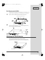
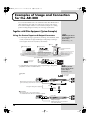


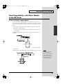
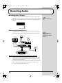


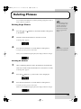
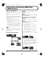
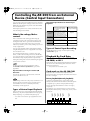
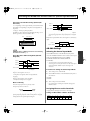
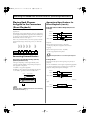

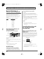
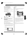
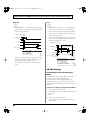
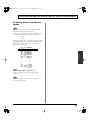


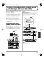
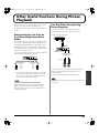
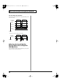

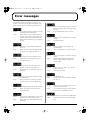
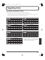
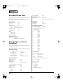
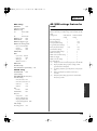
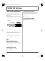


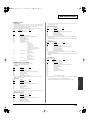


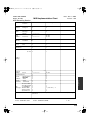
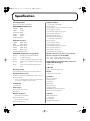
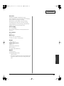
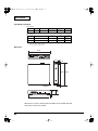


![to a copy of the presentation! [ PDF 3659 kB ]](http://vs1.manualzilla.com/store/data/005993145_1-0ef1bf04b92f9350e985abe9a695cb4d-150x150.png)