1
Preface, Table of Contents
SIMATIC
System Software for
M7-300 and M7-400
Installation and Operation
User Manual
This manual is part of the documentation
package with the order number:
Product Overview
1
Installing on PC or Programming
Device
2
Installing the M7-300/400
Systems
3
Operator and Monitor Interface
4
Using Mass Storage
5
Low-Level Debugger
6
Loadable Drivers
7
6ES7802–0FA14–8BA0
Appendix
Operating Systems and
Performance Characteristics
A
CLI Commands
B
Debugger Commands
C
System Status List SZL
D
Diagnostic Data
E
Glossary, Index
C79000-G7076-C850-02
Safety Guidelines
This manual contains notices which you should observe to ensure your own personal safety, as well as to
protect the product and connected equipment. These notices are highlighted in the manual by a warning
triangle and are marked as follows according to the level of danger:
!
!
!
Danger
indicates that death, severe personal injury or substantial property damage will result if proper precautions are not taken.
Warning
indicates that death, severe personal injury or substantial property damage can result if proper precautions are not taken.
Caution
indicates that minor personal injury or property damage can result if proper precautions are not taken.
Note
draws your attention to particularly important information on the product, handling the product, or to a
particular part of the documentation.
Qualified Personnel
Only qualified personnel should be allowed to install and work on this equipment. Qualified persons are
defined as persons who are authorized to commission, to ground, and to tag circuits, equipment, and sys–
tems in accordance with established safety practices and standards.
Correct Usage
Note the following:
!
Warning
This device and its components may only be used for the applications described in the catalog or the
technical description, and only in connection with devices or components from other manufacturers which
have been approved or recommended by Siemens.
This product can only function correctly and safetly if it is transported, stored, set up and installed correctly, and operated and maintained as recommended.
Trademarks
SIMATICR, SIMATIC HMIR and SIMATIC NETR are registered trademarks of SIEMENS AG.
Some of the other designations used in these documents are also registered trademarks; the owner’s
rights may be violated if they are used by third parties for their own purposes.
Copyright Siemens AG 1998 All rights reserved
Disclaimer of Liability
The reproduction, transmission or use of this document or its contents
is not permitted without express written authority. Offenders will be
liable for damages. All rights, including rights created by patent grant or
registration of a utility model or design, are reserved.
We have checked the contents of this manual for agreement with the
hardware and software described. Since deviations cannot be precluded
entirely, we cannot guarantee full agreement. However, the data in this
manual are reviewed regularly and any necessary corrections included in
subsequent editions. Suggestions for improvement are welcomed.
Siemens AG
Automation and Drives Group
Industrial Automation Systems
P.O.Box 4848, D- 90327 Nuremberg
Index-2
Siemens Aktiengesellschaft
E Siemens AG 1998
Technical
data
subject to
System
Software
forchange.
M7-300 and M7-400 Installation and Operation
C79000-G7076-C850-02
C79000-G7076-C850-02
Preface
Purpose
This manual is intended as support documentation for the installation and
operation of M7 300 and M7 400 automation systems under M7 RMOS32
operating system control. It provides information on the following topics:
The M7 RMOS32 hardware and software environment
Installation of the system software on PC or PG
Installation of the system software on the M7-300 or M7-400 PLC system
Settings and configuration options
Operating the M7-300 or M7-400 via remote terminal
The M7 RMOS32 command line interpreter (CLI)
The M7 RMOS32 low-level debugger
Audience
This manual is intended primarily for M7-300 and M7-400 automation system
set-up and start-up personnel.
Scope of This Manual
The manual applies for M7-300 and M7-400 automation systems under
M7-SYS RT V 4.0 operating system control.
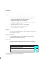
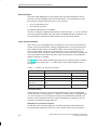
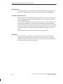
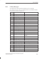
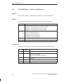
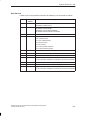
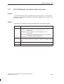
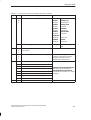
What is New?
This manual provides the following new topics and reference information on
changes and extensions of functions supported by version V4.0 of the system
software.
Topic
Chapter
Released operating system configurations: M7 RMOS32 on hard disk and M7
RMOS 32 with MS DOS on memory card
3.4, 3.5
Modifying system configuration files using the SIMATIC Manager
3.9
Communication via Industrial Ethernet (TCP/IP)
A.1
PING command for TCP/IP
B.22
System Software for M7-300 and M7-400 Installation and Operation
C79000-G7076-C850-02
iii
Preface
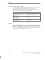
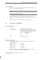
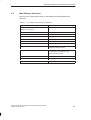
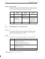
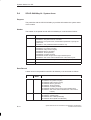
Scope of the Documentation Package
The system software for M7-300 and M7-400 programmable controllers that use
the M7-SYS RT software package is documented in a three-manual
documentation package which can be ordered separately from the M7-SYS RT
software package. The manuals are listed in the table below.
Manual
Contents
System Software for M7-300 and M7-400
Installation and Operation
User Manual
Installing and operating M7-300 and
M7-400 programmable controllers
System Software for M7-300 and M7-400
Program Design
Programming Manual
Designing and writing C/C++ programs
System Software for M7-300 and M7-400
System and Standard Functions
Reference Manual
Detailed information on programming
with M7-SYS
Feedback
We need your help to enable us to provide you and future M7-SYS RT users with
optimum documentation. If you have any questions or comments on this manual,
please fill in the remarks form at the end of the manual and return it to the address
shown on the form. We would be grateful if you could also take the time to answer the
questions giving your personal opinion of the manual.
iv
System Software for M7-300 and M7-400 Installation and Operation
C79000-G7076-C850-02
Preface
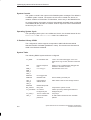
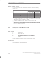
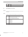
SIMATIC Customer Support Hotline
Contactable worldwide round the clock:
Nuremberg
Johnson City
Singapore
Simatic Basic Hotline
Nuremberg
Johnson City
SIMATIC BASIC Hotline
SIMATIC BASIC Hotline
Local time: Mo.-Fr. 8:00 to 18:00
Local time: Mo.-Fr. 8:00 to 17:00
Phone:
+49 (911) 895-7000
Phone:
+1 423 461-2522
Fax:
+49 (911) 895-7002
Fax:
+1 423 461-2231
E-Mail:
simatic.support@
nbgm.siemens.de
E-Mail:
simatic.hotline@
sea.siemens.com
SIMATIC Premium Hotline
Singapore
(Calls billed, only with
SIMATIC Card)
SIMATIC BASIC Hotline
Time:
Mo.-Fr. 0:00 to 24:00
Phone:
+49 (911) 895-7777
Fax:
+49 (911) 895-7001
System Software for M7-300 and M7-400 Installation and Operation
C79000-G7076-C850-02
Local time: Mo.-Fr. 8:30 to 17:30
Phone:
+65 740-7000
Fax:
+65 740-7001
E-Mail:
simatic@
singnet.com.sg
v
Preface
SIMATIC Customer Support Online Services
The SIMATIC Customer Support team provides you with comprehensive additional
information on SIMATIC products via its online services:
You can obtain general current information:
– On the Internet at http://www.ad.siemens.de/simatic
– Using fax polling no. 08765-93 02 77 95 00
Current Product Information leaflets and downloads which you may find useful
for your product are available:
– On the Internet at http://www.ad.siemens.de/support/html–00/
– Via the Bulletin Board System (BBS) in Nuremberg (SIMATIC Customer
Support Mailbox) at the number +49 (911) 895-7100.
To access the mailbox, use a modem with up to V.34 (28.8 kbps), whose
parameters you should set as follows: 8, N, 1, ANSI, or dial in using ISDN
(x.75, 64 kbps).
SIMATIC Training Center
Siemens also offers a number of training courses to introduce you to the SIMATIC S7
and M7 automation systems. Please contact your regional training center or the
central training center in Nuremberg, Germany for details:
D-90327 Nuremberg, Tel. (+49) (911) 895 3154.
Further Support
If you have any further questions about SIMATIC products, please contact your
Siemens partner at your local Siemens representative’s or regional office. You will find
the addresses in our catalogs and in Compuserve (go autforum).
vi
System Software for M7-300 and M7-400 Installation and Operation
C79000-G7076-C850-02
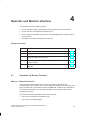
Table of Contents
1
2
3
4
5
Product Overview . . . . . . . . . . . . . . . . . . . . . . . . . . . . . . . . . . . . . . . . . . . . . . . . . . . . . .
1-1
1.1
M7 Optional Packages . . . . . . . . . . . . . . . . . . . . . . . . . . . . . . . . . . . . . . . . . . .
1-2
1.2
Operating Systems for M7-300 and M7-400 . . . . . . . . . . . . . . . . . . . . . . . . .
1-4
1.3
Brief Description of M7 RMOS32 . . . . . . . . . . . . . . . . . . . . . . . . . . . . . . . . . .
1-7
1.4
Brief Description of M7 RMOS32 for MS DOS . . . . . . . . . . . . . . . . . . . . . . .
1-8
Installing on PC or Programming Device . . . . . . . . . . . . . . . . . . . . . . . . . . . . . . . . .
2-1
2.1
Installing M7-SYS RT V4.0 . . . . . . . . . . . . . . . . . . . . . . . . . . . . . . . . . . . . . . .
2-1
2.2
Installation of Several M7-SYS Versions . . . . . . . . . . . . . . . . . . . . . . . . . . . .
2-3
Installing the M7 Programmable Control Systems . . . . . . . . . . . . . . . . . . . . . . . . .
3-1
3.1
General Remarks on Installation . . . . . . . . . . . . . . . . . . . . . . . . . . . . . . . . . . .
3-2
3.2
Data Security in the Event of a Power Failure . . . . . . . . . . . . . . . . . . . . . . .
3-7
3.3
Installing M7 RMOS32 on Memory Card . . . . . . . . . . . . . . . . . . . . . . . . . . . .
3-8
3.4
Installing M7 RMOS32 with MS DOS on Memory Card . . . . . . . . . . . . . . .
3-10
3.5
Installing M7 RMOS32 on Hard Disk . . . . . . . . . . . . . . . . . . . . . . . . . . . . . . .
3-12
3.6
Installing M7 RMOS32 with MS DOS on Hard Disk . . . . . . . . . . . . . . . . . .
3-14
3.7
Reinstallation of the M7 Operating System . . . . . . . . . . . . . . . . . . . . . . . . . .
3-15
3.8
Updating the Firmware . . . . . . . . . . . . . . . . . . . . . . . . . . . . . . . . . . . . . . . . . . .
3-16
3.9
Modifying Configuration Files . . . . . . . . . . . . . . . . . . . . . . . . . . . . . . . . . . . . .
3-19
3.10
The RMOS.INI File . . . . . . . . . . . . . . . . . . . . . . . . . . . . . . . . . . . . . . . . . . . . . .
3-23
3.11
The INITTAB File . . . . . . . . . . . . . . . . . . . . . . . . . . . . . . . . . . . . . . . . . . . . . . . .
3-26
Operator and Monitor Interface . . . . . . . . . . . . . . . . . . . . . . . . . . . . . . . . . . . . . . . . . .
4-1
4.1
Operation via Remote Terminal . . . . . . . . . . . . . . . . . . . . . . . . . . . . . . . . . . . .
4-1
4.2
Using the Command Line Interpreter (CLI) . . . . . . . . . . . . . . . . . . . . . . . . . .
4-3
4.3
Transferring Programs To and Deleting Programs From the M7
Programmable Control System . . . . . . . . . . . . . . . . . . . . . . . . . . . . . . . . . . . .
4-10
4.4
Starting Application Programs on the M7 Programmable Control System
4-15
4.5
Information and Control Functions for M7-300 and M7-400 . . . . . . . . . . . .
4-16
Using Mass Storage . . . . . . . . . . . . . . . . . . . . . . . . . . . . . . . . . . . . . . . . . . . . . . . . . . . .
5-1
5.1
Formatting Memory Cards and OSDs . . . . . . . . . . . . . . . . . . . . . . . . . . . . . .
5-2
5.2
Formatting Hard Disks and Diskettes . . . . . . . . . . . . . . . . . . . . . . . . . . . . . . .
5-3
System Software for M7-300 and M7-400 Installation and Operation
C79000-G7076-C850-02
vii
Table of Contents
6
7
A
B
viii
5.3
Hard Disk Partitioning Program HDPART . . . . . . . . . . . . . . . . . . . . . . . . . . .
5-4
5.4
Formatting Memory Cards and OSDs under MS-DOS . . . . . . . . . . . . . . . .
5-8
5.5
Using Memory Cards . . . . . . . . . . . . . . . . . . . . . . . . . . . . . . . . . . . . . . . . . . . .
5-10
5.6
The REMAP_A Program . . . . . . . . . . . . . . . . . . . . . . . . . . . . . . . . . . . . . . . . .
5-11
Low-Level Debugger . . . . . . . . . . . . . . . . . . . . . . . . . . . . . . . . . . . . . . . . . . . . . . . . . . . .
6-1
6.1
Task Mode and Monitor Mode . . . . . . . . . . . . . . . . . . . . . . . . . . . . . . . . . . . . .
6-2
6.2
Operator Control of the Debuggers . . . . . . . . . . . . . . . . . . . . . . . . . . . . . . . .
6-5
6.3
Syntax . . . . . . . . . . . . . . . . . . . . . . . . . . . . . . . . . . . . . . . . . . . . . . . . . . . . . . . . .
6-7
6.4
Debugger Commands . . . . . . . . . . . . . . . . . . . . . . . . . . . . . . . . . . . . . . . . . . . .
6-9
Loadable Drivers . . . . . . . . . . . . . . . . . . . . . . . . . . . . . . . . . . . . . . . . . . . . . . . . . . . . . . .
7-1
7.1
What You Need to Know About Loadable Drivers . . . . . . . . . . . . . . . . . . . .
7-1
7.2
Loading a Driver . . . . . . . . . . . . . . . . . . . . . . . . . . . . . . . . . . . . . . . . . . . . . . . .
7-2
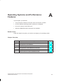
Operating Systems and Performance Features . . . . . . . . . . . . . . . . . . . . . . . . . . .
A-1
A.1
Performance Features of the CPUs and Function Modules . . . . . . . . . . . .
A-2
A.2
Configuration of M7 RMOS32 . . . . . . . . . . . . . . . . . . . . . . . . . . . . . . . . . . . . .
A-5
A.3
Main Memory Allocation . . . . . . . . . . . . . . . . . . . . . . . . . . . . . . . . . . . . . . . . . .
A-9
A.4
Configuration of M7 RMOS32 for DOS . . . . . . . . . . . . . . . . . . . . . . . . . . . . .
A-10
A.5
A.5.1
A.5.2
Components of M7 RMOS32-DOS . . . . . . . . . . . . . . . . . . . . . . . . . . . . . . . .
RM3PMEM.SYS . . . . . . . . . . . . . . . . . . . . . . . . . . . . . . . . . . . . . . . . . . . . . . . .
RM3RESET.SYS . . . . . . . . . . . . . . . . . . . . . . . . . . . . . . . . . . . . . . . . . . . . . . . .
A-15
A-16
A-17
A.6
Special Features under M7 RMOS32-DOS . . . . . . . . . . . . . . . . . . . . . . . . .
A-18
CLI Commands . . . . . . . . . . . . . . . . . . . . . . . . . . . . . . . . . . . . . . . . . . . . . . . . . . . . . . . . .
B-1
B.1
BYT8250 . . . . . . . . . . . . . . . . . . . . . . . . . . . . . . . . . . . . . . . . . . . . . . . . . . . . . . .
B-3
B.2
CANCEL . . . . . . . . . . . . . . . . . . . . . . . . . . . . . . . . . . . . . . . . . . . . . . . . . . . . . . .
B-5
B.3
CD . . . . . . . . . . . . . . . . . . . . . . . . . . . . . . . . . . . . . . . . . . . . . . . . . . . . . . . . . . . .
B-6
B.4
CHGKBD . . . . . . . . . . . . . . . . . . . . . . . . . . . . . . . . . . . . . . . . . . . . . . . . . . . . . .
B-7
B.5
COPY . . . . . . . . . . . . . . . . . . . . . . . . . . . . . . . . . . . . . . . . . . . . . . . . . . . . . . . . .
B-8
B.6
CPRI . . . . . . . . . . . . . . . . . . . . . . . . . . . . . . . . . . . . . . . . . . . . . . . . . . . . . . . . . .
B-10
B.7
DATE . . . . . . . . . . . . . . . . . . . . . . . . . . . . . . . . . . . . . . . . . . . . . . . . . . . . . . . . . .
B-11
B.8
DEL . . . . . . . . . . . . . . . . . . . . . . . . . . . . . . . . . . . . . . . . . . . . . . . . . . . . . . . . . . .
B-12
B.9
DEVICE . . . . . . . . . . . . . . . . . . . . . . . . . . . . . . . . . . . . . . . . . . . . . . . . . . . . . . . .
B-13
B.10
DIR . . . . . . . . . . . . . . . . . . . . . . . . . . . . . . . . . . . . . . . . . . . . . . . . . . . . . . . . . . . .
B-16
B.11
DISMOUNT . . . . . . . . . . . . . . . . . . . . . . . . . . . . . . . . . . . . . . . . . . . . . . . . . . . .
B-17
B.12
ECHO . . . . . . . . . . . . . . . . . . . . . . . . . . . . . . . . . . . . . . . . . . . . . . . . . . . . . . . . .
B-18
B.13
ERROR . . . . . . . . . . . . . . . . . . . . . . . . . . . . . . . . . . . . . . . . . . . . . . . . . . . . . . . .
B-19
B.14
EXIT . . . . . . . . . . . . . . . . . . . . . . . . . . . . . . . . . . . . . . . . . . . . . . . . . . . . . . . . . .
B-20
System Software for M7-300 and M7-400 Installation and Operation
C79000-G7076-C850-02
Table of Contents
C
B.15
FORMAT . . . . . . . . . . . . . . . . . . . . . . . . . . . . . . . . . . . . . . . . . . . . . . . . . . . . . . .
B-21
B.16
FTLFORM . . . . . . . . . . . . . . . . . . . . . . . . . . . . . . . . . . . . . . . . . . . . . . . . . . . . .
B-22
B.17
HELP . . . . . . . . . . . . . . . . . . . . . . . . . . . . . . . . . . . . . . . . . . . . . . . . . . . . . . . . . .
B-24
B.18
MD . . . . . . . . . . . . . . . . . . . . . . . . . . . . . . . . . . . . . . . . . . . . . . . . . . . . . . . . . . . .
B-25
B.19
MOUNT . . . . . . . . . . . . . . . . . . . . . . . . . . . . . . . . . . . . . . . . . . . . . . . . . . . . . . . .
B-26
B.20
NPX – Not for Later Versions . . . . . . . . . . . . . . . . . . . . . . . . . . . . . . . . . . . . .
B-27
B.21
PATH . . . . . . . . . . . . . . . . . . . . . . . . . . . . . . . . . . . . . . . . . . . . . . . . . . . . . . . . . .
B-28
B.22
PING . . . . . . . . . . . . . . . . . . . . . . . . . . . . . . . . . . . . . . . . . . . . . . . . . . . . . . . . . .
B-30
B.23
PROMPT . . . . . . . . . . . . . . . . . . . . . . . . . . . . . . . . . . . . . . . . . . . . . . . . . . . . . .
B-31
B.24
RD . . . . . . . . . . . . . . . . . . . . . . . . . . . . . . . . . . . . . . . . . . . . . . . . . . . . . . . . . . . .
B-32
B.25
RDISK . . . . . . . . . . . . . . . . . . . . . . . . . . . . . . . . . . . . . . . . . . . . . . . . . . . . . . . . .
B-33
B.26
RENAME . . . . . . . . . . . . . . . . . . . . . . . . . . . . . . . . . . . . . . . . . . . . . . . . . . . . . .
B-34
B.27
SCANDISK . . . . . . . . . . . . . . . . . . . . . . . . . . . . . . . . . . . . . . . . . . . . . . . . . . . . .
B-35
B.28
SESSION . . . . . . . . . . . . . . . . . . . . . . . . . . . . . . . . . . . . . . . . . . . . . . . . . . . . . .
B-37
B.29
SET . . . . . . . . . . . . . . . . . . . . . . . . . . . . . . . . . . . . . . . . . . . . . . . . . . . . . . . . . . .
B-38
B.30
START . . . . . . . . . . . . . . . . . . . . . . . . . . . . . . . . . . . . . . . . . . . . . . . . . . . . . . . . .
B-39
B.31
SYSTAT . . . . . . . . . . . . . . . . . . . . . . . . . . . . . . . . . . . . . . . . . . . . . . . . . . . . . . .
B-40
B.32
TIME . . . . . . . . . . . . . . . . . . . . . . . . . . . . . . . . . . . . . . . . . . . . . . . . . . . . . . . . . .
B-41
B.33
VER . . . . . . . . . . . . . . . . . . . . . . . . . . . . . . . . . . . . . . . . . . . . . . . . . . . . . . . . . . .
B-42
B.34
CLI Error Messages . . . . . . . . . . . . . . . . . . . . . . . . . . . . . . . . . . . . . . . . . . . . .
B-43
Debugger Commands . . . . . . . . . . . . . . . . . . . . . . . . . . . . . . . . . . . . . . . . . . . . . . . . . . .
C-1
C.1
Debugger Syntax Rules . . . . . . . . . . . . . . . . . . . . . . . . . . . . . . . . . . . . . . . . . .
C-3
C.2
ASM . . . . . . . . . . . . . . . . . . . . . . . . . . . . . . . . . . . . . . . . . . . . . . . . . . . . . . . . . . .
C-7
C.3
BASE . . . . . . . . . . . . . . . . . . . . . . . . . . . . . . . . . . . . . . . . . . . . . . . . . . . . . . . . . .
C-9
C.4
BREAKS . . . . . . . . . . . . . . . . . . . . . . . . . . . . . . . . . . . . . . . . . . . . . . . . . . . . . . .
C-10
C.5
CALCULATE . . . . . . . . . . . . . . . . . . . . . . . . . . . . . . . . . . . . . . . . . . . . . . . . . . .
C-11
C.6
CALL . . . . . . . . . . . . . . . . . . . . . . . . . . . . . . . . . . . . . . . . . . . . . . . . . . . . . . . . . .
C-12
C.7
CHANGE . . . . . . . . . . . . . . . . . . . . . . . . . . . . . . . . . . . . . . . . . . . . . . . . . . . . . .
C-13
C.8
CONT . . . . . . . . . . . . . . . . . . . . . . . . . . . . . . . . . . . . . . . . . . . . . . . . . . . . . . . . .
C-14
C.9
CPUREG . . . . . . . . . . . . . . . . . . . . . . . . . . . . . . . . . . . . . . . . . . . . . . . . . . . . . .
C-15
C.10
DIR . . . . . . . . . . . . . . . . . . . . . . . . . . . . . . . . . . . . . . . . . . . . . . . . . . . . . . . . . . . .
C-16
C.11
DISPLAY . . . . . . . . . . . . . . . . . . . . . . . . . . . . . . . . . . . . . . . . . . . . . . . . . . . . . . .
C-19
C.12
EVALUATE . . . . . . . . . . . . . . . . . . . . . . . . . . . . . . . . . . . . . . . . . . . . . . . . . . . . .
C-20
C.13
EXIT . . . . . . . . . . . . . . . . . . . . . . . . . . . . . . . . . . . . . . . . . . . . . . . . . . . . . . . . . .
C-21
C.14
EXITK . . . . . . . . . . . . . . . . . . . . . . . . . . . . . . . . . . . . . . . . . . . . . . . . . . . . . . . . .
C-22
System Software for M7-300 and M7-400 Installation and Operation
C79000-G7076-C850-02
ix
Table of Contents
D
x
C.15
FILL . . . . . . . . . . . . . . . . . . . . . . . . . . . . . . . . . . . . . . . . . . . . . . . . . . . . . . . . . . .
C-23
C.16
FREETASK . . . . . . . . . . . . . . . . . . . . . . . . . . . . . . . . . . . . . . . . . . . . . . . . . . . . .
C-24
C.17
GO . . . . . . . . . . . . . . . . . . . . . . . . . . . . . . . . . . . . . . . . . . . . . . . . . . . . . . . . . . . .
C-25
C.18
HALT . . . . . . . . . . . . . . . . . . . . . . . . . . . . . . . . . . . . . . . . . . . . . . . . . . . . . . . . . .
C-26
C.19
HELP . . . . . . . . . . . . . . . . . . . . . . . . . . . . . . . . . . . . . . . . . . . . . . . . . . . . . . . . . .
C-27
C.20
IN . . . . . . . . . . . . . . . . . . . . . . . . . . . . . . . . . . . . . . . . . . . . . . . . . . . . . . . . . . . . .
C-28
C.21
INHIB . . . . . . . . . . . . . . . . . . . . . . . . . . . . . . . . . . . . . . . . . . . . . . . . . . . . . . . . . .
C-29
C.22
KILL . . . . . . . . . . . . . . . . . . . . . . . . . . . . . . . . . . . . . . . . . . . . . . . . . . . . . . . . . . .
C-30
C.23
LINES . . . . . . . . . . . . . . . . . . . . . . . . . . . . . . . . . . . . . . . . . . . . . . . . . . . . . . . . .
C-31
C.24
LOADTASK . . . . . . . . . . . . . . . . . . . . . . . . . . . . . . . . . . . . . . . . . . . . . . . . . . . .
C-32
C.25
MONITOR . . . . . . . . . . . . . . . . . . . . . . . . . . . . . . . . . . . . . . . . . . . . . . . . . . . . . .
C-34
C.26
OUT . . . . . . . . . . . . . . . . . . . . . . . . . . . . . . . . . . . . . . . . . . . . . . . . . . . . . . . . . . .
C-35
C.27
QUALIFY . . . . . . . . . . . . . . . . . . . . . . . . . . . . . . . . . . . . . . . . . . . . . . . . . . . . . .
C-36
C.28
QUERY . . . . . . . . . . . . . . . . . . . . . . . . . . . . . . . . . . . . . . . . . . . . . . . . . . . . . . . .
C-37
C.29
REGS . . . . . . . . . . . . . . . . . . . . . . . . . . . . . . . . . . . . . . . . . . . . . . . . . . . . . . . . .
C-39
C.30
REPORT . . . . . . . . . . . . . . . . . . . . . . . . . . . . . . . . . . . . . . . . . . . . . . . . . . . . . . .
C-41
C.31
SET . . . . . . . . . . . . . . . . . . . . . . . . . . . . . . . . . . . . . . . . . . . . . . . . . . . . . . . . . . .
C-47
C.32
STACK . . . . . . . . . . . . . . . . . . . . . . . . . . . . . . . . . . . . . . . . . . . . . . . . . . . . . . . .
C-49
C.33
START . . . . . . . . . . . . . . . . . . . . . . . . . . . . . . . . . . . . . . . . . . . . . . . . . . . . . . . . .
C-50
C.34
STEP . . . . . . . . . . . . . . . . . . . . . . . . . . . . . . . . . . . . . . . . . . . . . . . . . . . . . . . . . .
C-51
C.35
SVC . . . . . . . . . . . . . . . . . . . . . . . . . . . . . . . . . . . . . . . . . . . . . . . . . . . . . . . . . . .
C-52
C.36
SWITCH . . . . . . . . . . . . . . . . . . . . . . . . . . . . . . . . . . . . . . . . . . . . . . . . . . . . . . .
C-54
C.37
TASK . . . . . . . . . . . . . . . . . . . . . . . . . . . . . . . . . . . . . . . . . . . . . . . . . . . . . . . . . .
C-55
C.38
TCB . . . . . . . . . . . . . . . . . . . . . . . . . . . . . . . . . . . . . . . . . . . . . . . . . . . . . . . . . . .
C-56
C.39
TCD . . . . . . . . . . . . . . . . . . . . . . . . . . . . . . . . . . . . . . . . . . . . . . . . . . . . . . . . . . .
C-57
C.40
Debugger Error Messages . . . . . . . . . . . . . . . . . . . . . . . . . . . . . . . . . . . . . . . .
C-58
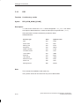
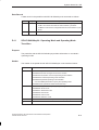
System Status List SZL . . . . . . . . . . . . . . . . . . . . . . . . . . . . . . . . . . . . . . . . . . . . . . . . .
D-1
D.1
Overview of the System Status List (SZL) . . . . . . . . . . . . . . . . . . . . . . . . . .
D-2
D.2
Structure of an SZL Partial List . . . . . . . . . . . . . . . . . . . . . . . . . . . . . . . . . . . .
D-3
D.3
SZL-ID . . . . . . . . . . . . . . . . . . . . . . . . . . . . . . . . . . . . . . . . . . . . . . . . . . . . . . . . .
D-4
D.4
Possible SZL Partial Lists . . . . . . . . . . . . . . . . . . . . . . . . . . . . . . . . . . . . . . . .
D-5
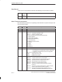
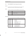
D.5
SZL-ID W#16#xy11 - Module Identification . . . . . . . . . . . . . . . . . . . . . . . . . .
D-6
D.6
SZL-ID W#16#xy12 - CPU Characteristics . . . . . . . . . . . . . . . . . . . . . . . . . .
D-7
D.7
SZL-ID W#16#xy13 - User Memory Areas . . . . . . . . . . . . . . . . . . . . . . . . . .
D-8
D.8
SZL-ID W#16#xy14 - System Areas . . . . . . . . . . . . . . . . . . . . . . . . . . . . . . .
D-10
System Software for M7-300 and M7-400 Installation and Operation
C79000-G7076-C850-02
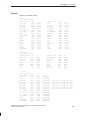
Table of Contents
D.9
SZL-ID W#16#xy15 - Block Types . . . . . . . . . . . . . . . . . . . . . . . . . . . . . . . . .
D-11
D.10
SZL-ID W#16#xy22 - Interrupt Status . . . . . . . . . . . . . . . . . . . . . . . . . . . . . .
D-12
D.11
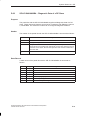
SZL-ID W#16#xy24 - Operating Mode and Operating Mode Transition . .
D-13
D.12
SZL-ID W#16#xy32 - Communication Status Data . . . . . . . . . . . . . . . . . . .
D-16
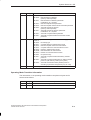
D.13
Data Record for the Partial List Extract with SZL-ID W#16#0132,
Index W#16#0001 . . . . . . . . . . . . . . . . . . . . . . . . . . . . . . . . . . . . . . . . . . . . . . .
D-17
Data Record for the Partial List Extract with SZL-ID W#16#0132,
Index W#16#0005 . . . . . . . . . . . . . . . . . . . . . . . . . . . . . . . . . . . . . . . . . . . . . . .
D-18
Data Record for the Partial List Extract with SZL-ID W#16#0132,
Index W#16#0008 . . . . . . . . . . . . . . . . . . . . . . . . . . . . . . . . . . . . . . . . . . . . . . .
D-19
D.16
SZL-ID W#16#xy91 - Module Status Information . . . . . . . . . . . . . . . . . . . . .
D-20
D.17
SZL-ID W#16#xy92 - Rack/Station Status Information . . . . . . . . . . . . . . . .
D-23
D.18
SZL-ID W#16#xyA0 - Diagnostic Buffer . . . . . . . . . . . . . . . . . . . . . . . . . . . .
D-25
D.19
SZL-ID W#16#00B1 - Module Diagnostic Information . . . . . . . . . . . . . . . . .
D-26
D.20
SZL-ID W#16#00B2 - Diagnostic Data Record 1 with
Geographical Address . . . . . . . . . . . . . . . . . . . . . . . . . . . . . . . . . . . . . . . . . . .
D-27
SZL-ID W#16#00B3 - Module Diagnostic Data via Logical
Base Address . . . . . . . . . . . . . . . . . . . . . . . . . . . . . . . . . . . . . . . . . . . . . . . . . . .
D-28
SZL-ID W#16#00B4 – Diagnostic Data of a DP Slave . . . . . . . . . . . . . . . .
D-29
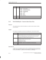
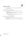
Diagnostic Data . . . . . . . . . . . . . . . . . . . . . . . . . . . . . . . . . . . . . . . . . . . . . . . . . . . . . . . .
E-1
D.14
D.15
D.21
D.22
E
Glossary
Index
System Software for M7-300 and M7-400 Installation and Operation
C79000-G7076-C850-02
xi
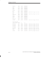
Table of Contents
xii
System Software for M7-300 and M7-400 Installation and Operation
C79000-G7076-C850-02
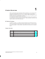
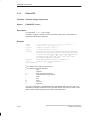
1
Product Overview
STEP 7 and the M7 optional packages make it possible for you to use high-level
programming languages such as C or C++ as well as graphic programming
software such as CFC (Continuous Function Chart) to write user programs for the
M7-300 and M7-400 programmable controllers.
This chapter discusses the various options available for writing user programs for
M7-300 and M7-400 programmable controllers. It also provides an overview of the
system software for M7-300 and M7-400.
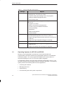
M7 Optional Packages
In addition to STEP 7, you need the system software for M7-300 and M7-400 as
well as a development environment for M7 programs (ProC/C++ or CFC) in order
to write the programs. These software components are described in the chapters
below.
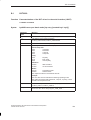
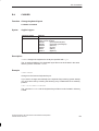
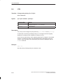
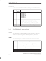
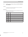
Chapter Overview
Section
Title
Page
1.1
M7 Optional Packages
1-2
1.2
Operating systems for M7-300 and M7-400
1-4
1.3
Brief description of M7 RMOS32
1-7
1.4
Brief description of M7 RMOS32 for MS DOS
1-8
System Software for M7-300 and M7-400 Installation and Operation
C79000-G7076-C850-02
1-1
Product Overview
1.1
M7 Optional Packages
STEP 7 provides you with the basic functionality you need in order to
generate and manage projects,
configure and initialize M7 system hardware,
configure network segments and connections,
manage symbolic data.
This functionality is provided regardless of whether your PLC system is a SIMATIC
S7 or a SIMATIC M7.
Because SIMATIC S7 and SIMATIC M7 systems use different operating systems
and runtime software, the PLC system affects primarily application programming.
In addition to STEP 7, you need the M7 optional packages in order to write M7
user programs.
Table 1-1
Optional Packages for M7 Programming
Software
M7-SYS RT
Contents
M7 RMOS32 operating system
M7 API system library
MPI support
CFC
M7-ProC/C++
Programming software for CFC applications
(CFC = Continuous Function Chart)
Linking of Borland development environment in STEP 7
Symbol import editor and generator
Organon debugger xdb386
Borland C++
Borland C++-development environment
Together with the M7 optional packages, STEP 7 also supports the following
activities:
Transfer of data to the M7 system via MPI
Scanning information about the M7 system
Making specific settings and executing a memory reset on the M7 system
1-2
System Software for M7-300 and M7-400 Installation and Operation
C79000-G7076-C850-02
Product Overview
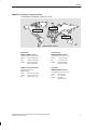
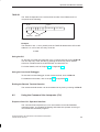
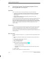
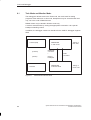
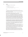
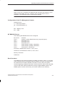
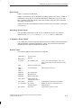
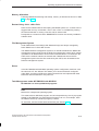
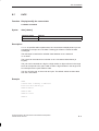
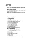
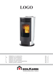
Dependencies
The diagram below shows the dependencies of the M7 optional packages:
C/C++-programs
CFC-programs
M7-ProC/C++
CFC for S7 and M7
Borland C++
M7-SYS RT
Figure 1-1
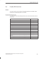
Table 1-2
Dependencies of the M7 Optional Packages for M7 Programming
Summary
Required M7 optional packages
Programs to be written
C/C++-programs
1. M7-SYS RT
2. M7-ProC/C++
3. Borland C++
CFC-programs
1. M7-SYS RT
2. CFC
3. Borland C++
Tools
Some of the specific tools needed to write M7 applications are integrated in
STEP 7, others in the M7 optional packages.
The table below tells you which tools are integrated in each package.
System Software for M7-300 and M7-400 Installation and Operation
C79000-G7076-C850-02
1-3
Product Overview
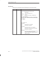
Table 1-3
Tools for Writing M7 User Programs
Package
STEP 7
Support
Installation of the M7 operating system
Management of the M7 PLC system
Transfer, starting and deleting of M7 user programs
Calling of status and diagnostic data
CPU memory reset
M7-SYS RT
Support through M7 operating system and system software
services for:
Program run control
Memory and resources management
Access to CPU and SIMATIC hardware
Interrupt handling
Diagnostics
Status monitoring and
Communication
M7-ProC/C++
Support through integrated code generation (integration of
the Borland development environment in STEP 7)
Support through linking of project symbols into the source
code and
Support through integrated debugger functionality
Borland C++
Support for the writing of C and C++ programs
CFC
Support for writing, testing, and debugging of CFC
programs and
Support for starting and executing CFC programs
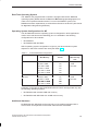
1.2
Operating Systems for M7-300 and M7-400
Because of its standardized PC architecture, the M7-300 and M7-400
programmable controllers constitute a programmable expansion of the SIMATIC
automation platform. The user programs for SIMATIC M7 can be written in a
high-level language such as C or in the CFC graphic language.
For applications written in the high-level programming languages C and C++, the
services provided by the operating system are extremely important. The operating
system performs the following tasks for these applications:
Accessing the hardware
Managing resources
System linking
Communicating with other system components
1-4
System Software for M7-300 and M7-400 Installation and Operation
C79000-G7076-C850-02
Product Overview
Real-Time Operating System
The SIMATIC M7 programmable controller is equipped with the M7 RMOS32
operating system (RMOS stands for Real-time Multitasking Operating System) in
order to accomplish automation tasks. For use in the SIMATIC system, M7
RMOS32 has been expanded by a call interface referred to as M7-API (API stands
for Application Programming Interface).
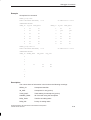
Operating System-Configurations for M7
The M7 RMOS32 real-time operating system is designed for 32-bit applications
used to solve real-time and multitasking jobs. It is available in the following
configurations for M7 modules:
M7 RMOS32
M7 RMOS32 with MS-DOS
Which operating system configuration is right for your M7 automation system
depends on which M7 modules are used (see Table 1-4).
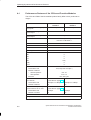
Table 1-4
Software/Hardware Configurations
Operating System
M7 RMOS32
M7 RMOS32 with
MS-DOS
MS
DOS
Module/
Main Memory
PROFIBUS DP
Yes/No
Installation on
Mass Storage
Unit
FM 356-4 / 4MB
No
Memory card
FM 356-4 / 8MB
Yes
4 MB
CPU 388-4 / 8MB
Yes
or hard disk
FM 456-4 / 16MB
Yes
CPU 488-3 / 16MB
Yes
CPU 486-3 / 16MB
Yes
CPU 388-4 / 8MB
No
FM356-4 / 8MB
No
Memory card
4 MB
FM 456-4 / 16MB
Yes
or hard disk
CPU 488-3
488 3 / 16MB
Yes
CPU 486-3 / 16MB
Yes
Hardware configurations with PROFIBUS-DP and TCP/IP are supported only with
the following operating systems:
M7 RMOS32 with at least 8 MB main memory
M7 RMOS32 with MS-DOS with 16 MB main memory
Additional Hardware
M7 RMOS32 with MS-DOS can be used only on M7 modules equipped with a
VGA monitor and keyboard via the IF962-VGA interface submodule.
System Software for M7-300 and M7-400 Installation and Operation
C79000-G7076-C850-02
1-5
Product Overview
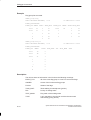
Mass Storage
M7 CPU modules and M7 application modules are equipped with the following
types of mass storage (see Table 1-5):
Memory cards (such as those in S7-CPUs)
Hard disk and diskette
All programmable M7 modules can be optionally equipped with a hard disk and
a 3.5 inch diskette drive via the MSM expansion board. As is the case with the
memory card, you can address the diskette on both the PC or programming
device and the M7-300/400 system.
On-board silicon disk (OSD)
This mass storage medium has the same performance characteristics as a
hard disk drive on which application programs can be stored. The FM 456-4
application module can be optionally equipped with an OSD.
Table 1-5
Mass Storage for M7 Systems
Mass Storage
Capacity
M7-300 Module
M7-400 Module
Hard disk
from 512MB
MSM 378
MSM 478
3.5 inch diskette
1.44MB
MSM 378
MSM 478
Memory Card
2*), 4, 8, 16 MB
CPU 388-4
FM 356-4
CPU 488/486-3
FM 456-4
OSD
4MB
-
Optional in
FM 456-4
*)
Not for a complete operating system
Note
For details on which system variants are supported by the current product version
as regards their main memory configurations and mass storage media, please
refer to Table 1-4 on page 1-5.
1-6
System Software for M7-300 and M7-400 Installation and Operation
C79000-G7076-C850-02
Product Overview
1.3
Brief Description of M7 RMOS32
Characteristic Features
M7 RMOS32 has the following characteristic features:
Preconfigured operating system variant for M7-300 and M7-400 CPUs and FMs
Sole control of the hardware by M7 RMOS32
Defined response times in the microsecond or millisecond range, real-time
capability for measuring, open-loop control and closed-loop control
Device Control
The following devices can be controlled by M7 RMOS32:
Four M7 RMOS32 consoles via EGA/VGA
One M7 RMOS32 console on COM1 and one on COM2
One printer on LPT1 (Centronics interface)
One memory card
One on-board silicon disk (OSD)
MSM 378 or MSM 478 mass storage module with one hard disk and one 1.44
MB diskette drive
Interrupts
M7 RMOS32 handles all interrupts.
File Management System
All drives (diskette, hard disk, memory card and OSD) are managed by the
RMOS’s HSFS file management system (HSFS stands for High Speed File
System). An automatic hard disk recognition facility integrates the hard disk in the
HSFS.
Command Line Interpreter (CLI)
Similar to the DOS command line interpreter but with commands for M7 RMOS32.
The M7 RMOS32 console is used for CLI entries.
Low-Level Debugger
Integrated low-level debugger. The debugger is serviced via the M7 RMOS32
console.
System Software for M7-300 and M7-400 Installation and Operation
C79000-G7076-C850-02
1-7
Product Overview
1.4
Brief Description of M7 RMOS32 for MS DOS
Characteristic Features
M7 RMOS32 for MS DOS has the following characteristic features:
Preconfigured real-time multitasking operating system for PC-compatible
systems
MS-DOS V6.22 executes as M7 RMOS32 task
Defined response times in the microsecond or millisecond range, real-time
capability for measuring, open-loop control and closed-loop control
Booting
MS-DOS is always booted first. M7 RMOS32 is started by MS-DOS via a special
load program.
Device Control
The graphic card and the keyboard are controlled by MS-DOS.
All drives (diskette, hard disk, etc.) known to BIOS are controlled by MS-DOS.
The interrupt controller and the timer chip are controlled by M7 RMOS32. The
functions necessary for MS-DOS are simulated.
Other devices and interfaces can be handled by either MS-DOS or M7 RMOS32.
This is specified in the configuring phase.
Interrupt Handling
Timer interrupts are serviced by M7 RMOS32. The timer interrupt for MS-DOS is
simulated by M7 RMOS32.
Keyboard, hard disk and diskette interrupts are handled by MS-DOS.
All other interrupts can be handled by either MS-DOS or M7 RMOS32. This is
specified in the configuring phase.
File Management System
MS-DOS’s own file management system is used.
The data media are made accessible to M7 RMOS32.
1-8
System Software for M7-300 and M7-400 Installation and Operation
C79000-G7076-C850-02
Product Overview
Memory Allocation
The memory area from address 0 to address 10FFFFH is always reserved for
MS-DOS.
The memory area starting with address 110000H is allocated to M7 RMOS32
during booting.
Monitor and Keyboard
Under MS DOS, the monitor and the keyboard can be alternately allocated to MS
DOS or M7 RMOS32 via hot key <Ctrl>+<Esc>. Under M7 RMOS32, keyboard
and monitor can be allocated to four different consoles with <F1>...<F4>.
Interaction Between M7 RMOS32 Multitasking and MS DOS
In contrast to the MS DOS file management system, M7 RMOS32 also permits
quasi-parallel file operations, for example simultaneous reading and writing of files
on the diskette or hard disk. One advantage of this functionality is that, while a
diskette is being formatted, parallel file operations for real-time tasks on other
mass media (hard disk, memory card) are possible.
Note
Under M7 RMOS32, DOS calls without multitasking capability are interlocked and
the requests thus serviced in succession.
For mass storage operations, this means, for instance, that file operations for
real-time tasks are halted while a diskette is being formatted (under DOS).
Please note that no file access operations may take place under MS-DOS during
the execution of real-time tasks.
Restart
The MS-DOS task can be restarted with the key combination <Ctrl>+<Alt>+<Del>.
A restart boots only MS-DOS, not M7 RMOS32.
During the restart, specific M7 RMOS32 tasks may be started. However, these
tasks must first be logged on or off via special functions.
Error Handling
Privilege violations in the MS-DOS task are intercepted by M7 RMOS32. The
MS-DOS program is then automatically aborted.
Illegal I/O commands, that is access operations to a device under M7 RMOS32
control, are intercepted by M7 RMOS32.
System Software for M7-300 and M7-400 Installation and Operation
C79000-G7076-C850-02
1-9
Product Overview
1-10
System Software for M7-300 and M7-400 Installation and Operation
C79000-G7076-C850-02
Installing on PC or Programming Device
2
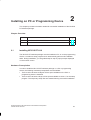
This chapter provides information needed for successful installation of the M7-SYS
RT software package.
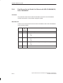
Chapter Overview
Section
2.1
Title
Page
2.1
Installation of M7-SYS RT V4.0
2-1
2.2
Installation of several M7-SYS versions
2-3
Installing M7-SYS RT V4.0
The M7-SYS RT software package must be installed on PC or on the programming
device. It contains a setup program which automatically performs all installation
tasks. During installation, you are guided step for step by input prompts displayed
on the monitor screen.
Hardware Prerequisites
In order to install the M7-SYS RT software package on a PC or programming
device, the following hardware prerequisites must be fulfilled:
There must be at least 10 Mbytes of free space available on the PC’s or
programming device’s hard disk
There must be at least 1 Mbyte of free space available on drive C: for the setup
program. The temporary setup files are erased following successful installation.
System Software for M7-300 and M7-400 Installation and Operation
C79000-G7076-C850-02
2-1
Installing on PC or Programming Device
Software Prerequisites
In order to install the M7-SYS software package on a PC or programming device,
the following software prerequisites must be fulfilled:
The Windows 95 or Windows NT operating system must be installed on the
PC or programming device
The STEP 7 basic software version 4.02 must be installed on the PC or
programming device. M7-SYS can be installed on STEP 7 version 3.2 as well,
but in this case the new functionality is not available. For instructions on how to
install STEP 7, please refer to the STEP 7 User Manual.
You need administrator’s privileges in order to install M7-SYS RT under
Windows NT.
Procedure
1. Exit all STEP 7 applications.
2. Insert the first diskette in the drive and start the Setup program for M7-SYS.
The M7-SYS files are then copied to the PC/programming device and entries
are made in the MS Windows files. Important information on handling will be
displayed during the Setup process.
3. Upon completion, an event box is displayed to show successful termination of
the installation procedure.
4. Before you use M7-SYS, your PC/programming device must be restarted. Only
then do all the settings become active.
!
Caution
M7-SYS registers itself in MS Windows 95/NT system files. With MS Windows
utilities such as Explorer, you cannot move M7-SYS files or folders, nor can you
modify M7-SYS data in the MS Windows register. Programs will not run properly
after such changes.
Uninstall
Use the Control Panel to uninstall M7-SYS RT as usual in Windows 95/NT.
Note
If more than one M7-SYS version are installed on the PC/programming device,
you must uninstall them together. If you uninstall only one version, the common
files are deleted.
When removing M7-SYS from the PC/programming device (Windows 95 only),
entries which were made in the WINSTART.BAT file by the system are not deleted.
2-2
System Software for M7-300 and M7-400 Installation and Operation
C79000-G7076-C850-02
Installing on PC or Programming Device
2.2
Installation of Several M7-SYS Versions
STEP 7 V3.1 allows working with two or more M7-SYS versions simultaneously on
the PC/programming device. Please consider the following, when using several
M7-SYS versions:
Installation sequence:
Newer versions must be installed after the older ones in order to prevent
overwriting the newer common files by the old ones.
Uninstall:
Uninstall of only one of the M7-SYS versions is not possible because of the
common data. If more than one versions are installed, you must deinstall them
together.
Downward compatibility of user programs is not supported.
I.e. programs that were compiled and linked with M7-SYS RT V4.0 cannot be
executed on an M7-300/400 with an M7-SYS V2.0 or V1.2 operating system.
Upward compatibility of user programs is supported except for Windows 3.11
programs. I.e. programs that were compiled and linked with M7-SYS V1.2 or
V2.0 can be executed on an M7-300/400 with an M7-SYS RT V4.0 operating
system (M7 RMOS32 possibly with MS DOS).
Selecting the operating system version for an M7-300/400
You can select the operating system version during the installation of the operating
system on an M7 CPU or M7 FM (using the command PLC > Manage M7
System).
Updating from V1.2 to V2.0 or V4.0
When replacing a CPU 488-4/5 by a CPU 486-3 or a CPU 488-3, you have to
update from V1.2 to V2.0 or V4.0.
System Software for M7-300 and M7-400 Installation and Operation
C79000-G7076-C850-02
2-3
Installing on PC or Programming Device
2-4
System Software for M7-300 and M7-400 Installation and Operation
C79000-G7076-C850-02
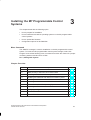
Installing the M7 Programmable Control
Systems
3
This chapter deals with the following topics:
S
How to prepare for installation
S
How to install and reinstall an operating systems on the M7 programmable
control systems
S
How to update the firmware
S
Configuration options for M7 RMOS32
Menu Command
The SIMATIC manager is used for installation on the M7 programmable control
system. To invoke the M7 programmable control system manager, select ”M7
Program” and call the following menu command from within the context of a project
containing stations with M7 CPUs or FMs:
PLC
"
Manage M7 System
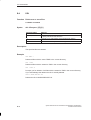
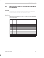
Chapter Overview
Section
Description
Page
3.1
General Remarks on Installation
3-2
3.2
Data Security in the Event of a Power Failure
3-7
3.3
Installing M7 RMOS32 on Memory Card
3-8
3.4
Installing M7 RMOS32 with MS DOS on Memory Card
3-10
3.5
Installing M7 RMOS32 on Hard Disk
3-12
3.6
Installing M7 RMOS32 with MS DOS on Hard Disk
3-14
3.7
Reinstallation of the M7 Operating System
3-15
3.8
Updating the Firmware
3-16
3.9
Modifying Configuration Files
3.9
3.10
The RMOS.INI File
3-23
3.11
The INITTAB File
3-26
System Software for M7-300 and M7-400 Installation and Operation
C79000-G7076-C850-02
3-1
Installing the M7 Programmable Control Systems
3.1
General Remarks on Installation
Reason for Installation
The reason for installation is the transfer of a complete operating system
configuration, including M7 system software, to the target medium, the mass
storage unit of an M7 system.
This section provides an overview of installation options and basic procedures. You
will find step-by-step installation instructions in the sections below as well as in the
On-Line Help for M7 Programmable Control System Manager.
Installation Options
Depending on the mass storage unit of the M7 programmable control system, a
distinction is made between:
1. Installation on hard disk. If this is the first installation, the M7 programmable
control system does not yet have an executable operating system, and an MPI
link is not yet possible.
2. Installation on memory card. A memory card can accommodate a complete M7
RMOS32 operating system with application programs.
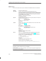
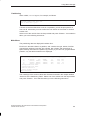
Basic Procedures
Proceed as follows to install an operating system:
1. Select object “M7 program” in your project.
2. Call the menu command
PLC Manage M7 System.
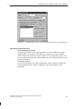
3. Open the “Install Operating System” tab.
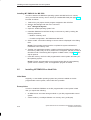
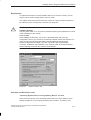
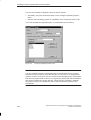
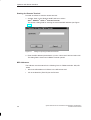
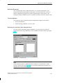
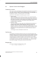
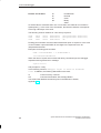
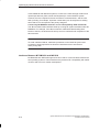
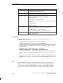
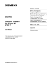
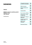
4. Make the following selections (see Figure 3-1):
– Operating system configuration
– Operating system version in the programming device (only if you have
installed several versions of M7-SYS on the programming device/PC)
– Medium
– Local drive (only on programming device/PC with Windows 95) and remote
drive when using medium “MPI/RFS”
5. Activate “Install”
3-2
System Software for M7-300 and M7-400 Installation and Operation
C79000-G7076-C850-02
Installing the M7 Programmable Control Systems
Figure 3-1
”Install Operating System” Tab (on programming device/PC with Windows NT)
Operating System Versions
In the programming device:
Select here the version of the operating system you have installed on your M7
programmable control system. This step is only required if you have installed
several versions of the M7-SYS option software on the programming device. You
can only select those versions that are released for the module (see also M7-SYS
Product Information).
In the PLC system:
If an on-line connection to the M7 programmable control system is possible, the
current operating system version is displayed in this tab provided it can be
determined.
System Software for M7-300 and M7-400 Installation and Operation
C79000-G7076-C850-02
3-3
Installing the M7 Programmable Control Systems
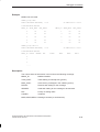
Selecting an Operating System
Select an operating system configuration from the ”Possible Configurations” field.
Selection of an operating system configuration depends on the type of application
programs to run on the M7 programmable control system. Table 3-1 shows when
to select which operating system. Also note the hardware dependencies in Table
1-4 on page 1-5.
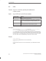
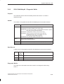
Table 3-1
Operating System Configurations
Application Programs
Operating System Configuration
M7 RMOS32 applications only
M7 RMOS32
M7 RMOS32- and
MS DOS applications
M7 RMOS32 & MS DOS
The memory requirement for M7 RMOS32 without MS DOS is no more than
3 Mbytes on the target medium. To this you must add the memory requirements of
your application programs.
See the M7-SYS Product Information for details of which operating system
configurations are released for which mass storage media. Non-released
configurations cannot be installed.
Selecting a Medium
The following installation media are presented as options in the “Medium” field:
MPI/RFS:
Select ”MPI/RFS” (RFS stands for Remote File System) if the operating system
is to be installed on the M7 programmable control system’s hard disk. In order
to use this installation medium, an MPI link must be established between
PC/programming device and M7 programmable control system.
When using MPI/RFS, the operating system is always installed on the M7
programmable control system’s hard disk. For all installations via MPI/RFS, you
also need a boot medium (see page 3-5).
Memory Card
Select “Memory card” when the operating system is to be installed on the
memory card. The operating system and the application programs are
transferred from the programming device to the memory card.
The memory card is then inserted in the M7 programmable control system and
the M7 programmable control system is booted.
In order to use a memory card, you require a programming device 720/740/760
or a PC with external EPROM programming facility.
3-4
System Software for M7-300 and M7-400 Installation and Operation
C79000-G7076-C850-02
Installing the M7 Programmable Control Systems
Note
A 1.44 MB diskette can hold a minimal M7 RMOS32 system, but it cannot be used
as target medium for installation of the operating system on the M7-300 or
M7-400. You can use a floppy disk as boot medium or as data medium for
application programs.
A suitable selection list supports choosing of a medium. “Memory card”, for
example, is included in the selection list only when your PC or programming device
is equipped with a memory card drive.
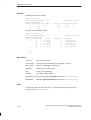
Selecting a Local Drive and a Remote Drive
When using ”MPI/RFS” as installation medium, an MPI communication link is
established between the local drive of the PC/ programming device and a drive on
the M7 programmable control system.
Local drive:
The selection list shows you the available drive identifiers on the PC or
programming device from which you may choose. The local drive must be selected
only on PCs or programming devices with Windows 95, under Windows NT the
selection is deactivated.
Remote drive:
The selection list shows you the available drive identifiers on the M7
programmable control system from which you can select the required mass
storage unit. Normally (unless specified otherwise), the drives are allocated as
shown in the following table.
Table 3-2
Drive Allocation (Default) on the M7 Programmable Control System
Drive
Remote Drive Identification
MS DOS
M7 RMOS32
A: or B:
M0:
C:, D:, ...
C:, D:, ...
D:, E:, ...With hard disk
C: Without hard disk
M1:
Memory card
Hard disk
On board silicon disk
System Software for M7-300 and M7-400 Installation and Operation
C79000-G7076-C850-02
3-5
Installing the M7 Programmable Control Systems
Boot Medium
When you install the operating system on the M7 programmable control system’s
hard disk, you also need a boot medium. The term boot medium is used to identify
a data carrier from which the programmable control system is booted on power-up.
The boot medium contains a minimal version of the M7 RMOS32 operating
system. During booting, the sections of the operating system needed for executing
the application programs and for communication purposes are loaded into work
memory.
Following boot medium start up, an MPI link can be established between the PC or
programmable device and the M7 programmable control system.
Data media with booting capability for the M7 programmable control systems are:
3.5 inch/1.44 MB diskettes or
Memory card with a capacity of 2 MB or more
Installing MS DOS
Before installing the operating system configuration with MS DOS, you must install
MS DOS V6.22 on the M7 programmable control system.
Partitioning the Hard Disk
If you install the operating system on the hard disk, we recommend that you create
two partitions for reasons of data security in the event of a power failure (see
Section 3.2). You can partition the hard disk using the following calls:
hdpart under M7 RMOS32 (see Chapter 5)
fdisk under MS DOS
Formatting the Target Medium
As a rule, the target medium is formatted prior to initial installation of the operating
system. In the case of M7 operating system configurations, you must format the
target medium in the following cases:
Operating System
Formatting of Target Medium
M7 RMOS32
Prior to each complete installation or reinstallation, since
M7 RMOS32 must always be written to the start of the
memory when running without MS DOS.
M7 RMOS32 with
MS DOS
Prior to the initial installation of MS DOS.
During installation of M7 RMOS32 without MS DOS, you will be prompted to
format the hard disk as target medium. You will find details on how to proceed in
Chapter 5.
3-6
System Software for M7-300 and M7-400 Installation and Operation
C79000-G7076-C850-02
Installing the M7 Programmable Control Systems
Installing into an MPI Subnet
If you use a boot medium when installing M7 RMOS32 on an M7 CPU or FM that
has been assigned MPI parameters differing from the standard setting, then
sporadically a serious fault can occur during power up and the installation is
aborted.
Remedy: In order to install the operating system choose one of the following:
disconnect the module from the MPI subnet and connect the programming
device locally during installation or
configure the MPI subnet twice. Proceed as follows:
– Configure the MPI subnet by assigning the standard MPI parameters.
– Install the operating system.
– Configure the MPI subnet again and reassign the parameters as required.
3.2
Data Security in the Event of a Power Failure
Concept
The M7-300/400 automation computer has several different mass storage media:
Hard disk, memory card and OSD, whose file systems are managed by the
operating system.
!
Caution
If a power failure occurs during a write operation to a mass data storage unit, data
may be corrupted or lost.
As the system software (operating system, configuration files, etc.) is also located
on the mass storage medium, a power failure during a write access can result in
the system no longer being bootable.
To solve this problem, we recommend that you work with at least two mass
storage media (or two partitions on the hard disk):
One boot drive (boot partition) containing the operating system and the files
relevant to the system and to which no write accesses are made during
operation and
One data drive (data partition) containing the user programs and the areas of
read-only, back-up and load memory areas, and to which write accesses during
operation are permitted.
On hard disk the boot partition is always C:.
System Software for M7-300 and M7-400 Installation and Operation
C79000-G7076-C850-02
3-7
Installing the M7 Programmable Control Systems
Procedure
You can use the following procedure to ensure data consistency on the mass
storage medium in the event of a power failure:
Install the operating system on the boot partition on the hard disk or on its own
mass storage medium. Ensure that no write accesses are made to the boot
partition or mass storage medium of the operating system during operation.
This ensures that the operating system and the system data remain intact
following a power failure, meaning a complete restart can always be performed.
Do not create the directories for the back-up memory, the permanent load
memory and the read-only memory on the same drive as the operating system
but on the data drive on which you write during operation. For this purpose, you
must assign the relevant path names to the environment variables BACKDIR,
RAMDIR and ROMDIR in the \ETC\INITTAB file on the boot drive.
Install the user programs on the data drive.
3.3
Installing M7 RMOS32 on Memory Card
Initial State
Your M7 programmable control system has no hard disk or diskette drive.
Prerequisites
In this case, you can use the memory card as target medium. A memory card can
accommodate a complete M7 RMOS32 operating system with application
programs (see Table 3-2).
Requirements:
A memory card drive on your programming device 720/740/760 or a PC with
external EPROM programming facility
A memory card with a capacity of 4 MB or more
3-8
System Software for M7-300 and M7-400 Installation and Operation
C79000-G7076-C850-02
Installing the M7 Programmable Control Systems
Procedure
Proceed as follows to activate a memory card-resident M7 RMOS32 operating
system:
1. Select from your project the M7 program assigned to M7-CPU/FM
2. Start the M7 Manager with the menu command
PLC Manage M7 System
3. Open the “Install Operating System” tab.
4. Install an M7 RMOS32 operating system locally on the memory card by making
the following selections:
– Medium: “Memory card”
– Possible configuration: “M7 RMOS32”
5. Select “Install”. Information relating to current events is displayed in the dialog
field.
Result: The operating system and the complete M7 system software are
transferred to the memory card.
6. Transfer your application program, together with all associated project data, to
the memory card locally. To do so, switch to the “Programs” tab and proceed as
described under “Transferring M7 Programs via Data Carrier”, page 4-13. This
step is optional.
7. Insert the memory card into the M7 programming control system and restart the
system. Set up the BIOS if required (see the Hardware Manuals for more
details).
Result: The M7 programming control system boots with the new operating
system. Your application program is started.
System Software for M7-300 and M7-400 Installation and Operation
C79000-G7076-C850-02
3-9
Installing the M7 Programmable Control Systems
3.4
Installing M7 RMOS32 with MS DOS on Memory Card
Initial State
Your M7 programming control system has no hard disk or diskette drive.
Prerequisites
In this case, the memory card is used as target medium. A memory card can
accommodate a complete M7 RMOS32 operating system with application
programs (see Table 3-2). Depending on the size of the memory card (capacity of
8 MB or more), you can also install MS DOS or a subset of MS DOS on the card.
Requirements:
A memory card drive on your programming device 720/740/760 or a PC with
external EPROM programming facility
A memory card with a capacity of 8 MB or more
MS DOS installation diskettes
Basic Procedure
Proceed as follows to install an M7 RMOS32 operating system with MS DOS on a
memory card:
1. Format the memory card and install MS DOS or the parts of MS DOS you need
on it. Carry out this installation in the DOS box of Windows 95/NT.
2. Install M7 RMOS32 for MS DOS on the memory card and use it to start your
M7 programming control system. Carry out this installation under STEP 7
control.
3-10
System Software for M7-300 and M7-400 Installation and Operation
C79000-G7076-C850-02
Installing the M7 Programmable Control Systems
Installing MS DOS on Memory Card
Proceed as follows to install MS DOS on a memory card:
1. Insert MS DOS V6.22 installation diskette 1 and the memory card in the
appropriate drives on your PC or programming device.
2. Call the following command in the DOS box on your PC or programming
device:
under Windows 95: <STEP7_Directory>\s7bin\s7oformx <m:> /s<a:>
under Windows NT: <STEP7_Directory>\s7bin\s7ofornx <m:> /s<a:>
where
– <m:> is the identifier of the memory card drive on the PC or programming
device
– <a:> is the identifier of the diskette drive on the PC or programming device
Result: The memory card is formatted as boot medium, and the MS DOS
system files are copied to it, that is, io.sys, msdos.sys and command.com.
You must then copy the portions of MS DOS which you need for your
application from the MS DOS diskettes to the memory card. The data on the
MS DOS installation diskettes are compressed, and cannot be processed with
Setup until they have been decompressed. The following steps must be taken
in order to copy files directly from an installation diskette without using Setup:
3. Copy file EXPAND.EXE from installation diskette 1 to the PC’s or programming
device’s hard disk.
4. Insert the diskette containing the file to be decompressed into drive A:.
If you do not know which diskette contains the desired file, open the
PACKING.LST file on installation diskette 1. The PACKING.LST file contains
the names of the files on the installation diskettes.
5. Enter the following in response to the input prompt:
expand x: \filename1 y: directory \filename2
For parameter x, enter the identifier for the diskette drive from which you are
copying. For filename1, enter the name of the compressed file. For parameter
y, enter the identifier for the target drive (memory card). for directory, enter the
name of the directory in which the decompressed file is to be stored. For
filename2, enter the name of the file which is to contain the decompressed
data.
Result: The compressed file is stored in decompressed form on your target
drive.
Repeat for all files to be transferred to the memory card.
Following completion of MS DOS installation, you can install M7 RMOS32 for
MS DOS on the memory card.
System Software for M7-300 and M7-400 Installation and Operation
C79000-G7076-C850-02
3-11
Installing the M7 Programmable Control Systems
Installing M7 RMOS32 for MS DOS
In order to start an M7 RMOS32 operating system with MS DOS on a memory
card, you need the memory card on which you installed MS DOS (see page 3-11).
Proceed as follows:
1. Select from your project the M7 program assigned to M7-CPU/FM.
2. Start the M7 Manager with the menu command
PLC " Manage M7 System
3. Open the “Install Operating System” tab.
4. Install M7 RMOS32 for MS DOS locally on the memory card by making the
following selections:
– Medium: “Memory card”
– Possible configuration: “M7 RMOS32 & MS DOS”
5. Select “Install”. Information relating to current events is displayed in the dialog
field.
Result: The operating system and the complete M7 system software are
transferred to the memory card.
6. Transfer your application program, together with all associated project data, to
the memory card locally. To do so, switch to the “Programs” tab and proceed as
described under “Transferring M7 Programs via Data Carrier”, Page 4-13. This
step is optional.
7. Insert the memory card in the M7 programmable control system and start your
M7 operating system.
Result: The M7 programmable control system boots with the new operating
system from the memory card. Your application program is started.
3.5
Installing M7 RMOS32 on Hard Disk
Initial State
Originally, no executable operating system has yet been installed on the M7
programmable control system, and no MPI link is possible.
Prerequisites
In order to install M7 RMOS32 on the M7 programmable control system’s hard
disk, you require the following:
3-12
S
An MSM 378 or 478 mass storage module on your M7 programmable control
system
S
A boot medium (1.44 Mbyte diskette or a memory card 2 Mbytes)
System Software for M7-300 and M7-400 Installation and Operation
C79000-G7076-C850-02
Installing the M7 Programmable Control Systems
Procedure
Proceed as follows:
1. Select from your project the M7 program assigned to M7-CPU/FM and start the
M7 Manager with the menu command:
PLC Manage M7 System
2. Open index ”Install Operating System” and make the following selections:
– Medium: “MPI/RFS”
– Possible configuration: “M7 RMOS32”
– Local drive: The first free drive, for instance F:
– Remote drive: C: for hard disk
3. Select “Install”
You will be informed of current events and instructed to enter any necessary
information by prompts displayed in the dialog fields.
Essentially, you must do the following:
4. Select a boot medium (floppy disk or memory card).
Result: A minimal M7 RMOS32 operating system will be installed on the
selected boot medium
5. Insert the boot medium in the M7 programmable control system’s drive and
start the M7 programmable control system. Result: The M7 programmable
control system is booted with the new operating system and an MPI link
established between the PC or programming device and the M7 programmable
control system.
6. Partition and format the hard disk via RTI (Remote Terminal Interface) or at the
local console of the M7 programmable control system. For more information
please refer to Sections 3.2 and Section 5.2.
Result: The hard disk is partitioned and formatted. The M7 RMOS32 operating
system and any application programs are then installed on the M7-300 or
M7-400 hard disk via the MPI link.
To transfer your application program to the M7 programmable control system,
open the “Programs” tab and proceed as described under “Transferring
Programs via MPI/RFS”, page 4-12.
7. Restart the M7 programmable control system via the mode selector and, if
necessary, set up the BIOS. Result: The M7 programmable control system
boots with the new operating system from the hard disk. Your application
program, if any, is started.
System Software for M7-300 and M7-400 Installation and Operation
C79000-G7076-C850-02
3-13
Installing the M7 Programmable Control Systems
3.6
Installing M7 RMOS32 with MS DOS on Hard Disk
Initial State
Originally, no executable operating system is installed on the M7 programmable
control system, and no MPI connection is possible.
Prerequisites
The following is required to install M7 RMOS32 with MS DOS on the M7
programmable control system’s hard disk:
S
An MSM 378 or 478 mass storage module on your M7 programmable control
system
S
A boot medium (1.44 MB diskette or a memory card 2 MB)
S
MS DOS installation diskettes. MS DOS V6.22 must be installed on the M7
programmable control system’s hard disk.
Procedure
To install M7 RMOS32 with MS DOS on an M7 programmable control system with
hard disk, you must carry out the following steps in the order given:
1. Select from your project the M7 program assigned to M7-CPU/FM and start the
M7 Manager with the menu command:
PLC " Manage M7 System
2. Open index ”Install Operating System” and make the following selections:
– Medium: “MPI/RFS”
– Possible configuration: “M7 RMOS32 & MS DOS”
– Local drive: The first free drive, for example F:
– Remote drive: C: for hard disk
3. Select “Install”.
You will be informed of current events and instructed to enter any necessary
information by prompts displayed in the dialog fields. Essentially, you must do
the following:
4. Select a boot medium (floppy disk or memory card). Result: A minimal M7
RMOS32 operating system is installed on the boot medium.
5. Select drives for the operating system and data (see Section 3.2).
3-14
System Software for M7-300 and M7-400 Installation and Operation
C79000-G7076-C850-02
Installing the M7 Programmable Control Systems
6. Insert the boot medium in the M7 programmable control system’s drive and
start the M7 programmable control system. Result: The M7 programmable
control system boots with the new operating system and an MPI link is
established between the PC or programming device and the M7 programmable
control system. Then, M7 RMOS32 for MS DOS and any application programs
are installed on the M7-300 or M7-400 system’s hard disk via the MPI link.
To transfer your application program to the M7 programmable control system,
open the “Programs” tab and proceed as described under “Transferring M7
Programs via MPI/RFS”, page 4-12.
7. Restart the M7 programmable control system via the mode selector and set
BIOS Setup if necessary. Result: The M7 programmable control system boots
with the new operating system from the hard disk. Your application program, if
any, is started.
3.7
Reinstallation of the M7 Operating System
Initial State
If the M7 programmable control system’s hard disk already contains an operating
system, you can initiate reinstallation via “MPI/RFS”, that is, you can change,
expand or upgrade the operating system on your M7 programmable control
system.
See the M7-SYS Product Information for details of which operating system
configurations are released for which mass storage devices.
Note
During reinstallation the configuration files such as for example INITTAB or
RMOS.INI are also transferred to the M7 system. If you have modified these files
locally on the M7 without using the SIMATIC Manager menu command
PLC Manage M7 System, you must save them before reinstallation, in order to
avoid overwriting.
System Software for M7-300 and M7-400 Installation and Operation
C79000-G7076-C850-02
3-15
Installing the M7 Programmable Control Systems
Reinstallation on Hard Disk
Table 3-3 shows you what you must do in the different cases to reinstall an
operating system on the hard disk. The basic procedure is the same as that used
for initial installation, and is described in detail in Sections 3.5 and 3.6.
Table 3-3
Reinstallation on Hard Disk
Current OS
OS To Be (Re)installed
M7 RMOS32
M7 RMOS32 with MS DOS
M7 RMOS32
Same as initial installation of
M7 RMOS32
Format destination medium,
install MS DOS locally, re-install
M7 RMOS32
M7 RMOS32 with
MS DOS
Same as initial installation of
M7 RMOS32
Only one new M7 RMOS32
component is reinstalled
Reinstallation on Memory Card
Reinstallation of M7 RMOS32 on memory card always entails complete
reinstallation. As a rule, only the M7 RMOS32 component is reinstalled in the case
of M7 RMOS32 with MS DOS.
Additional Information
You will find details on individual steps as well as additional information on
installing the various operating system configurations in the M7 programmable
control system manager’s on-line Help screens.
3.8
Updating the Firmware
On the M7-300/400 CPUs and application modules there is firmware specific to the
module, such as the BIOS. You can update the firmware via the M7 programmable
control system management.
The firmware can be updated independently of or in conjunction with the system
software for M7-300/M7-400.
The version of the firmware in the M7 programmable control system and in the
programming device is displayed in the ”Update Firmware” tab. This makes it
easier to check to see if the firmware requires to be updated: Updating of the
firmware is only necessary if the firmware version in the M7 programmable control
system is older than the firmware version in the programming device.
If you install the operating system via MPI/RFS, the firmware version is checked
automatically. If the version of the firmware on the M7 programmable control
system does not match the installed operating system, you will receive the relevant
message.
3-16
System Software for M7-300 and M7-400 Installation and Operation
C79000-G7076-C850-02
Installing the M7 Programmable Control Systems
Requirement
To update the firmware of an M7-300/M7-400 CPU or function module, you will
require a boot medium (floppy disk or memory card).
The update must be performed within the context of a project which contains the
M7 stations (CPUs or FMs) with a selected ”M7 Program”.
!
Caution
Hardware damage:
The line power must on no account be switched off during the update as this could
result in damage to the module.
Loss of data:
After updating the firmware, you must run the BIOS setup and save your
configuration even if you choose to work with the default values (see Section 12.4
in the S7-400, M7-400 Programmable Controllers Module Specifications,
Reference Manual and Chapter 10 of the manual M7-300 Programmable
Controller, Installation and Hardware). Any changes made to the BIOS settings
before updating will be lost and must be entered again.
Figure 3-2
”Update Firmware” Tab
Versions and Revision Levels
”Operating System Version in Programming Device” list field
Select here the version of the operating system that you want to install or have
already installed on your M7 programmable control system. This step is only
System Software for M7-300 and M7-400 Installation and Operation
C79000-G7076-C850-02
3-17
Installing the M7 Programmable Control Systems
required if you have installed several versions of the M7-SYS option software on
the programming device.
Firmware version, hardware version (revision level)
The following versions are displayed if an MPI connection to the M7 programmable
control system exists:
S
Current firmware version in the programming device
S
Firmware version in the M7 programmable control system
S
M7 programmable control system hardware revision level
Procedure
To update the firmware of an M7 programmable control system, follow the steps
outlined below:
1. Select the M7 program container associated with the M7 CPU or FM.
2. Call the menu command
PLC " Manage M7 System and open the ”Update Firmware” tab (see
Figure 3-2).
3. Select the boot medium: floppy disk or memory card.
4. Select the version of the operating system from the list field ”Operating System
Version in Programming Device”. This step is only required if you have installed
several versions of the M7-SYS option software on the programming device.
5. Click the ”Create” button.
Result: The boot medium is formatted (with a warning) and the new firmware is
installed on it.
6. Insert the boot medium into the M7 programmable control system and start the
M7-CPU/FM.
Result: If you boot the M7 programmable control system with this data
medium, the firmware is updated automatically. The update is completed when
the following LEDs are lit continuously:
– The USR LED on the M7-300 CPU/FM
– The USR1 LED on the M7-400 CPU/FM
7. Remove the boot medium from the M7 programmable control system and boot
it from the preset mass storage medium (memory card, hard disk, etc.).
Note
If the firmware on the boot medium is incompatible with the module type or older
than the existing firmware version, the firmware not updated and the fault LED
(SF LED on the M7-300 and INTF LED on the M7-400) lights up. This also applies
if an attempt is made to install the identical firmware version.
3-18
System Software for M7-300 and M7-400 Installation and Operation
C79000-G7076-C850-02
Installing the M7 Programmable Control Systems
In the Event of a Fault
Take the following measures, in the event of a fault:
1. Remove the boot medium from the M7 programmable control system.
2. Check in case the version of the BIOS on the M7-300/400 module is higher
than the version of the new firmware. If this is the case, an update is not
required and is also not possible.
3. Check whether the module in your project agrees with the module type of the
M7 programmable control system. If this is not the case, adapt your project
accordingly and carry out the firmware update again.
3.9
Modifying Configuration Files
Configuration Files
M7-SYS RT V 4.0 supports modification of the configuration files of M7 RMOS32
in the SIMATIC Manager of STEP 7. Under the “Configure Operating System” tab
in the “Manage M7 PLC System” window, you can select the following operating
system configuration files and edit them.
File
Description
See
RMOS.INI
Configuration file for M7 RMOS 32
Sec. 3.10
INITTAB
Initialization file for M7 system server
Sec. 3.11
CLISTART.BAT
Initialization file for CLI
Sec. 4.2
HOSTS
List of nodes for TCP/IP
Programming
Manual, Sec. 8.12
SERVICES
TCP/IP services
Programming
Manual, Sec. 8.12
The files are stored for each CPU or FM module in the relevant “M7 program”
container of the project.
Basic Procedures
You can modify the configuration files as follows:
Edit the files that are located in the project on the PC or programming device
and then load them onto the M7 system. This procedure is recommended, in
particular, on installing a new version of the operating system, but it is also
recommended generally.
Load the configuration files that are located on the M7 system into the
programming device, edit them and load them back onto the M7 system. This
procedure is appropriate when a previously installed operating system is being
modified, e.g. for entering new communication nodes in the HOSTS file.
System Software for M7-300 and M7-400 Installation and Operation
C79000-G7076-C850-02
3-19
Installing the M7 Programmable Control Systems
You can load modified configuration files into the M7 system:
Separately, using the “Download” button in the “Configure Operating System”
tab or
With the entire operating system on installation in the “Install Op. System” tab.
If you use the default configuration files, no modifications are necessary.
Figure 3-3
“Configure Operating System” Tab
Note
It is only possible to edit the configuration files for the M7-SYS RT V4.0 system
software and to load them into the M7-300/400. This function is not supported for
previous versions of M7-SYS. We recommend that all changes to the configuration
files are only implemented on the PC or programming device and that the modified
files are then loaded into the M7-300/400. This prevents inconsistency between
the project in the PC or programming device and the operating system on the
M7-300/400.
3-20
System Software for M7-300 and M7-400 Installation and Operation
C79000-G7076-C850-02
Installing the M7 Programmable Control Systems
Modifying the Configuration Files in the Project
Proceed as follows:
1. Select the M7 program container to which the M7 module (CPU or FM) is
assigned.
2. Call the menu command PLC " Manage M7 PLC System and open the
“Configure Op. System” tab (see Figure 3-3).
3. In the “Medium” field, select the transfer medium for loading
If your M7 system has a hard disk, select “MPI/RFS”, otherwise select another
data carrier.
4. Select the local drive and the partner drive. It is only possible to select these
options, if you have set the medium as “MPI/RFS”.
Local drive (only under Windows 95):
Select the drive identifier via which you want to access the M7 system. It is
recommended that you use the first available character.
Partner drive:
Select the drive that you want to access, i.e. the drive on which the operating
system is installed.
5. In the “Configuration” field, select the operating system whose configuration
files you would like to edit.
6. Select the file that you want to edit from the “Editable Files” field.
7. Click the “Edit in PG” button
The selected file will be opened using the notepad editor.
8. Edit the file and save it.
9. Repeat steps 6 to 8 for each file that you want to edit.
10.Load the configuration files by:
S
Clicking the “Download” button to load the marked configuration file(s) onto the
medium indicated or
S
Installing this operating system configuration onto the M7-300/400, in which
case, the modified configuration files are transferred automatically.
System Software for M7-300 and M7-400 Installation and Operation
C79000-G7076-C850-02
3-21
Installing the M7 Programmable Control Systems
Modifying the Configuration Files in the M7 System
Proceed as follows:
1. Select the M7 program container assigned to the M7 module (CPU or FM).
2. Call the menu command PLC Manage M7 PLC System and open the
“Configure Op. System” tab (see Figure 3-3).
3. In the “Medium” field, select the transfer medium for uploading into the
programming device (PG).
If your M7 system has a hard disk, select “MPI/RFS”, otherwise select another
data carrier.
4. Select the local drive and the partner drive. It is only possible to select these
options, if you have set the medium as “MPI/RFS”.
Local drive (only under Windows 95):
Select the drive identifier via which you want to access the M7 system. It is
recommended that you use the first available character.
Partner drive:
Select the drive that you want to access, i.e. the drive on which the operating
system is installed.
5. In the “Configuration” field, select the operating system whose configuration
files you would like to edit.
6. Select the file that you want to edit from the “Editable Files” field.
7. Click the “Upload” button
The selected file will be loaded into the programming device from the M7
system and overwrites the file of the same name in the project.
8. Click the “Edit in PG” button
The selected file will be opened using the notepad editor.
9. Edit the file and save it.
10.Repeat steps 5 to 8 for each file that you want to edit.
11. Click the “Download” button to load the marked configuration file(s) onto the
medium indicated.
When Do the Changes Become Effective?
The changes to the configuration files become effective as follows:
3-22
File
Changes become effective..
RMOS.INI and INITTAB
When the M7-300/400 is rebooted
CLISTART.BAT
When the CLI is restarted (<CTRL>+<R>)
HOSTS and SERVICES
On the next access via one of the functions of the
socket library
System Software for M7-300 and M7-400 Installation and Operation
C79000-G7076-C850-02
Installing the M7 Programmable Control Systems
3.10
The RMOS.INI File
The rmos.ini file is a software configuration file for the M7 RMOS32 operating
system. It is an ASCII text format file, and can be edited to tailor the operating
system’s performance to suit your requirements. The file is read and evaluated on
operating system start-up. Any new parameters go into force on a cold operating
system restart.
Note
The operating system is preconfigured for your M7-300 or M7-400 hardware
configuration; as a rule, no changes in file rmos.ini are necessary.
Should any modifications to this file become necessary, please change only those
parts of the file discussed below.
run Command
The run command makes it possible to call an executable command from the
rmos.ini file. CLI commands are not available to run. In contrast to the other
configuration data, which have to be placed in a specific section, run may be
located anywhere in the file.
When the relevant line is encountered, the command specified with run is loaded
and executed. When it terminates, it is removed and processing of the file
continues.
Example:
The run command to activate the German keyboard is:
RUN=M0:\BIN\chgkbd KBDGER
File Structure
Keywords enclosed in brackets separate the file into sections. Each section may
contain several entries. Each entry is defined on a separate line. A value
assignment is made using an equal sign followed by one or more parameters.
Entries can be omitted, in which case they are replaced by default values. A
comment for a line must begin with a semicolon or the letters REM.
System Software for M7-300 and M7-400 Installation and Operation
C79000-G7076-C850-02
3-23
Installing the M7 Programmable Control Systems
RMOS Section
Some of the entries which may be included in the RMOS section are as follows:
[RMOS]
Identifies the RMOS section
picenable
Enable for specific hardware interrupt request inputs in the
programmable interrupt control blocks. Drivers and other RMOS routines
which rely on hardware interrupts enable the relevant inputs themselves.
With picenable, you can enables additional interrupt inputs needed for
your own interrupt service routines.
Example for enabling IRQ12 and IRQ15:
picenable=IRQ12,IRQ15
logsvcx
Specifies whether error messages of the system calls are to be output on
the monitor screen. Options:
YES
Output to screen
NO
No output to screen
Example for no output to screen:
logsvcx=NO
sysdev
Definition of the system console. Specifies the name of the device driver
(also see Appendix A.2).
Options:
BYT_COM1/2
For COM1 or COM2
BYT_EGA1 to 3 For EGA/VGA 1 to 3
(M7 RMOS32 without MS DOS only)
none
no system console
Default
sysdev=none
Example for system console on COM1:
sysdev=BYT_COM1
device
The device command loads a driver or generates a driver unit. The
syntax and parameters are described in Appendix B.9. The device
command calls in the rmos.ini file and in the CLI differ in the following
way: The device command is followed by:
a space – in the CLI
a ”=” character in the rmos.ini
Examples:
Load 3964 driver without generating a unit:
DEVICE=\M7RMOS32\3964.DRV
Generate a driver unit for SER8250 on COM2:
DEVICE=SER8250 COM2 IRQ:3 BASE:0x2F8 MODE:9600–N–8–1
Note
Activate the screen output of the error messages
logsvcx=YES
for test purposes only. During operation, this can lead to high task change times in
the execution of your program.
3-24
System Software for M7-300 and M7-400 Installation and Operation
C79000-G7076-C850-02
Installing the M7 Programmable Control Systems
!
Caution
If you have set up a system console on one of the serial interfaces COM1/COM2
with the entry:
sysdev=BYT_COM1
you must not use this serial interface for communication with one of the loadable
drivers 3964R or SER8250, otherwise the output of the system console will be
controlled by the new driver. It is directed to the port and can cause conflicts with
the communications partner, for example, if an error message is output on the
system console.
RMOS DOS Section
Some of the entries which may be included in the RMOS DOS section are as follows:
[RMOS DOS]
Identifies the RMOS DOS section
RESERVE_COMx
This entry reserves COM1, COM2 and so on for M7 RMOS32.
Default:
REM RESERVE_COM2
Each default includes a comment; the COM2 interface is also
available for DOS.
Remove the comment initiation letters REM to reserve the COM2
interface exclusively for M7 RMOS32.
MAX_PORT_
NUMBER
This entry disables the port shadow.
Default:
MAX_PORT_NUMBER = 0XFFFF
The value is preset and may not be changed.
System Software for M7-300 and M7-400 Installation and Operation
C79000-G7076-C850-02
3-25
Installing the M7 Programmable Control Systems
3.11
The INITTAB File
Contents
The INITTAB file contains calls for starting the M7 system servers and the user
programs. It is written in ASCII text format. The file is read and evaluated when the
operating system starts up. New entries become effective once the operating
system has been restarted.
Structure of the File
An entry has the following syntax:
<Start ID> <Path> [<Call parameter>]
Example:
0 \SRV\BASICSRV.EXE 340 1
The start ID can be 0, 1 or 2. The values 0 and 1 are reserved for the M7 system
servers. Application programs are entered with the start ID of 2.
The path is entered with reference to the main directory of the drive.
Call parameters are optional.
Each entry is specified in one line. You can use the “#” character to change the
subsequent characters into a comment.
!
Caution
The M7 system servers are preconfigured for your M7-300/400 hardware and software configuration. These calls must not be modified; any changes would affect
the system response!
Please only change the calls for the user programs, where necessary.
3-26
System Software for M7-300 and M7-400 Installation and Operation
C79000-G7076-C850-02
Operator and Monitor Interface
4
This chapter covers the following topics:
How to operate the M7 programmable control system via remote terminal
How to use the command line interpreter (CLI)
How to transfer application programs to the M7 programmable control system
and start them
Information and control functions you may use
Chapter Overview
Section
4.1
Title
Page
4.1
Operation via Remote Terminal
4-1
4.2
Using the Command Line Interpreter (CLI)
4-3
4.3
Transferring programs to and deleting them from the M7
programmable control system
4-10
4.4
Starting application programs on the M7 programmable
control system
4-15
4.5
Information and control functions for the M7-300 and
M7-400
4-16
Operation via Remote Terminal
What is a “Remote Terminal”?
The remote terminal interface (RTI) makes it possible to operate an M7
programmable control system from a PC or programming device as though it were
being operated via a local terminal under M7 RMOS32. An MPI link is required for
communications between the M7 programmable control system and the PC or
programming device.
You have the following possibilities via remote terminal:
Use of the command line interpreter (CLI)
Use of the low-level debugger
System Software for M7-300 and M7-400 Installation and Operation
C79000-G7076-C850-02
4-1
Operator and Monitor Interface
Starting the Remote Terminal
Proceed as follows to start the remote terminal:
1. Activate “Start” in the Windows 95/NT task bar to select:
Start " SIMATIC " STEP 7 " Remote Terminal
This opens a dialog field for entering the associated MPI address (see Figure
4-1).
Figure 4-1
Dialog for Opening the Remote Terminal
2. Enter the MPI address (the default is 2) in the “Host name” field and select OK.
The dialog field is closed and a RMOS console opened.
MPI Addresses
The address must be entered in the following form for FM456 modules: <H>,< T>
,where
4-2
S
<H> is the MPI address of CPU4xx in the MPI subnet and
S
<T> is the identifier (TSAP-ID) for the FM 456.
System Software for M7-300 and M7-400 Installation and Operation
C79000-G7076-C850-02
Operator and Monitor Interface
TSAP-ID
The TSAP-ID depends on the rack and slot number of the FM456, and is a
composite of the following:
Byte 1
Byte 0
0 0 0 0
Rack No.
Figure 4-2
1 1 0 0
Slot No.
Structure of the TSAP-ID
Example:
The FM456 in rack 1, slot 4 (240CH) has the TSAP-ID 9228 and the CPU’s MPI
address is 3. In this case, the entry would be:
3,9228
Using the CLI
To start the command line interpreter (CLI) via remote terminal, enter <CTRL>R.
You can skip entry of the start file by pressing the Enter key, which initiates
execution of default start file CLISTART.BAT and starts the CLI.
For further details, refer to Chapter 4.2 and Appendix B.
Using the Low-Level Debugger
To start the low-level debugger via the remote terminal, enter <CTRL>D.
For additional information, refer to Chapter 6 and Appendix C.
Ending the Remote Terminal Session
The remote terminal session can be terminated at any time by entering <CTRL>Z.
4.2
Using the Command Line Interpreter (CLI)
Purpose of the CLI: Operator Interface
The command line interpreter (CLI) is a user interface for the M7 RMOS32
operating system. CLI enables the starting and interactive operator servicing of
commands and reloadable programs.
System Software for M7-300 and M7-400 Installation and Operation
C79000-G7076-C850-02
4-3
Operator and Monitor Interface
Component Functions
The CLI comprises the following:
CLI task (shell)
Program manager
Reloadable commands
Runtime environment for reloadable tasks
CLI Start-up batch file CLISTART.BAT
CLI Task
In the RMOS system, the CLI is a dynamic task. The time period during which the
CLI task is executing is referred to as a session. A session can take place on any
console. The console on which a CLI session was started is the standard input and
output unit for that session. The CLI task builds on the program manager’s function
interface. The default priority for the task is 64.
Program Manager
The program manager manages all executing CLI commands.
Its most important jobs include the following:
– Locating programs via a search path
– Diverting input and output where applicable
– Management of background jobs
– Management of reusable code segments
– Aborting of tasks through <Ctrl>+<C> or CANCEL
– In-line commands
In-line commands are linked with the program manager and thus with the
RMOS operating system. They are called in the CLI task as subroutines.
The in-line commands are also available without file management system
(HSFS).
Reloadable Commands
Reloadable commands are programs which can be called via the CLI user
interface. For example, the commands dir, copy and rename are implemented
as reloadable programs.
4-4
System Software for M7-300 and M7-400 Installation and Operation
C79000-G7076-C850-02
Operator and Monitor Interface
Runtime Environment
The runtime environment is a fixed component of the CLI. It
– opens inputs and outputs stdin, stdout and stderr, taking into account any
rerouting;
– breaks the command line down into the C format (argc/argv);
– initializes C Runtime Library on a task-specific basis.
CLISTART.BAT
When a CLI session is started, a batch file can be opened, for example to set such
parameters as search path, prompt and current directory.
Starting the CLI
Options for starting the CLI include INITTASK and a dispatcher task which starts
the CLI in the event of unexpected input. Both options have been implemented,
that is to say, on system startup, the CLI is started on the main console. The CLI
can be started on all consoles with the key combination <Ctrl>+<R>.
When started by the INITTASK, the CLI calls the CLISTART.BAT file in the boot
drive’s main directory.
When started via dispatcher task <Ctrl><R>, the name used to execute a file with
the extension BAT is prompted. If <Return> is pressed without an entry being
made, the standard file (CLISTART.BAT) stipulated for starting by the INITTASK is
processed.
System Software for M7-300 and M7-400 Installation and Operation
C79000-G7076-C850-02
4-5
Operator and Monitor Interface
Commands and Programs Started by the CLI
Commands and programs started by the CLI are referred to as jobs. They can
execute in the foreground (in connection with the console) or in the background
(with no connection to the console on which they were started).
Jobs can be nested. Using batch files or the function interface, a job can start
other jobs. A calling job is referred to as father, called jobs as children. A child can
call other children. The CLI manages all tasks and commands started via the CLI
itself or via the CLI function interface as jobs. From the viewpoint of the nucleus,
however, there are also tasks which are started via SVC calls. These are not
known to the CLI, and are therefore not jobs.
All jobs are controlled by the CLI that started them. The CLI also manages the
following assignments:
Each job has a job number, which is assigned by the CLI on start-up.
Each job is assigned to the directory set at the time it is called.
For example, the command DIR a:\bin > list.txt is entered in the
current directory A:. File LIST.TXT is thus created or overwritten in directory A:
Each job is assigned a standard input, standard output and error output device.
In the case of foreground jobs, the CLI’s console is set for all input and output.
The NUL device is assigned as input and output device for background jobs.
The assignments can be diverted (see page 4-8).
Editing Commands
Keyboard entries on the command line are handled by the BYT driver. A separate
history buffer, in the specified length, is available for each CLI session, that is to
say, previously entered commands can be selected with the arrow keys.
Command lines can be edited with the following keys:
Letters, Numbers
Always overwrite existing characters
Arrow keys
The Right Arrow and Left Arrow keys move the cursor
The Up Arrow and Down Arrow keys copy a previously entered
command from the buffer to the command line
INS
Generates and inserts a space
DEL<Ctrl>
Replaces the character at the left of the cursor with a space
(Backspace)
Same as DEL
<Ctrl>+<A>
Deletes the line from the cursor position to the end of the line
<Ctrl>+<F>
Deletes the character at the cursor position
<Ctrl>+<H>
Same as Backspace
<Ctrl>+<X>
Deletes the line from the start to the current cursor position
<Ctrl>+<Z>
Terminates input during console copy, for instance the command
copy con file.txt.
4-6
System Software for M7-300 and M7-400 Installation and Operation
C79000-G7076-C850-02
Operator and Monitor Interface
Names
Names may contain all characters allowed in DOS. This means that, in names, all
characters greater than ASCII 0x21 which do not have one of the following
functions are allowed:
Dummy character:
In file names, the dummy character (joker, wildcard) “*” stands for indeterminate
name extensions of no more than the maximum permissible length.
In file names, the dummy character “?” identifies precisely one indeterminate
character.
Drive specifications:
Drive specifications are terminated with the “:” character.
Directory Names
Directory names must be separated from succeeding file or directory names by “/”
or “\”. These two characters are identical in their function.
For each job, there is a current directory. Paths and routes can be absolute, that is
to say, they may be specified beginning with the drive identifier, or relative, that is,
the structure is specified on the basis of the current directory. In the latter case, the
two dots “..” represent the higher directory.
Examples of valid file identification entries are:
C:\CLISTART.BAT
C:CLI\BIN\DIR.386
DIR.386
..\DIR.386
BIN\DIR.386
Extensions
Generally, the CLI uses DOS-compatible file names. Reloadable programs and
CLI commands may be specified without a file extension. The CLI searches for the
extension in a directory level in the following order:
386, EXE, BAT
Note
DOS programs existing in the form of .EXE files cannot be executed by the CLI.
The CLI converts the file names, directories and drives into upper-case letters.
The arguments on the command line, however, are forwarded as they are. A
program executing under CLI control may thus contain parameters written in lower
case.
System Software for M7-300 and M7-400 Installation and Operation
C79000-G7076-C850-02
4-7
Operator and Monitor Interface
Diverting Input and Output
Input to and output from a command or task can be diverted to a file or an
interface.
This is possible in the following cases:
All CLI commands
All programs which, through the use of standard C functions, read their input
from stdin and write their output to stdout or stderr.
stdout
Diversion is specified by entering one of the following options on the command
line:
> <File>
or
1> <File>)
diverts all output to stdout to the specified file. The file is created or overwritten.
>> <File>
or
1>> <File>
routes all output to stdout to the specified file. If the file already exists, outputs
are written at the end of the file; if the file does not yet exist, it is created.
stderr
The option
2> <File>
routes all output to stderr to the specified file. The file is created or overwritten.
2>> <File>
routes all output to stderr to the specified file. If the file already exists, outputs
are written at the end of the file. If the file does not yet exist, it is created.
4-8
System Software for M7-300 and M7-400 Installation and Operation
C79000-G7076-C850-02
Operator and Monitor Interface
stdin
The option
< <File>
causes input from stdin to be read from the specified file.
Examples:
DIR >NUL
DIR > DIR.LIS
A device name may be specified instead of a file name (COM1, LPT1, etc.). Any
device name used must be entered as BYT-driver-compatible unit in the RMOS
Catalog.
If output is to suppressed altogether, an option is available for diverting it to the
NUL file.
Accessing Drives
Under the RMOS file management system, drives (volumes) must be logged on
(MOUNT) prior to use. This can be done in several ways. A drive is logged on
automatically when a file is opened. The drive then remains logged on even when
the file open is terminated with error.
If an attempt is made to access a drive without explicitly opening a file, for instance
in the case of the command dir A:, the drive must be logged on with MOUNT
before it can be accessed.
A drive can also be logged on automatically with an appropriate PATH setting when
a command is not reached at all or is reached via a path element which does not
occur until later.
Printing Under M7 RMOS32
To print a file under M7 RMOS32 (without MS-DOS), enter the following command
in the CLI:
Printer on LPT port:
copy <filename> BYT_LPT1
Printer on COM port:
copy <filename> BYT_COM1
Descriptions of CLI Commands
You find detailed descriptions of CLI commands in Appendix B.
System Software for M7-300 and M7-400 Installation and Operation
C79000-G7076-C850-02
4-9
Operator and Monitor Interface
4.3
Transferring Programs To and Deleting Programs From the
M7 Programmable Control System
Application
STEP 7 provides options for doing the following using the M7 Manager:
S
Transferring M7 application programs with all associated project data either
separately or together with the operating system to the M7 programmable
control system
S
Deleting arbitrary software components (M7 programs) from the M7
programmable control system
You can also transfer M7 programs to the M7 PLC system and manage them with
the special development tools contained in the M7 optional packages, such as
CFC or the Organon debugger (refer to the documentation for the relevant option
software). These tools do not transfer the programs permanently to mass storage,
however, but only load them temporarily into the M7 programmable control
system’s RAM.
Prerequisites
In order to transfer application programs to the M7 programmable control system
via MPI, an operating system must be available which can start the M7-300 or
M7-400 and establish an MPI connection to the PC or programming device.
Apart from that, you can also install your M7 application program together with the
operating system.
Basic Procedure
Proceed as follows to transfer a C, C++ program to the M7 programmable control
system:
1. Select an M7 program container which is allocated to an M7 module (CPU or
FM).
2. In your project, call the menu command
PLC " Manage M7 System.
3. Open the “Programs” tab.
4. Make the following selections (see Figure 4-3):
– Programs on the programming device
– Transfer and target medium
– Local drive (only with Windows 95) and remote drive when using medium
“MPI/RFS”
5. Activate “Install”
All other activities depend on the medium selected.
4-10
System Software for M7-300 and M7-400 Installation and Operation
C79000-G7076-C850-02
Operator and Monitor Interface
Selecting Programs
The “Programming Device” field shows all C, C++ programs assigned in your
project to the M7 programmable control system. You can select one or more of
these for transferring programs to the M7 programmable control system. The
programs already available on the PLC system are listed in the “PLC system” field.
Transfer Medium
There are two ways of transferring the M7 application programs with STEP7:
On-line via MPI/RFS
Off-line via floppy diskette or memory card
Selecting a Local Drive and a Remote Drive
As is the case for operating system installation, you may select a local and a
remote drive when using “MPI/RFS” as the installation transfer medium (see page
3-4).
Figure 4-3
”Programs” Tab
Note
If the operating system is installed on the hard disk, we recommend, for data
security reasons (see Section 3.2), that you install the application programs on a
different drive to the operating system.
System Software for M7-300 and M7-400 Installation and Operation
C79000-G7076-C850-02
4-11
Operator and Monitor Interface
Transferring M7 Programs via MPI/RFS
In an on-line transfer, the required program sections are transferred directly via
MPI to the PLC system’s mass storage, and the relevant Start Batch files are
entered in the PLC system’s \etc\inittab file so that the programs can be started
automatically on the next system startup. In addition, a special description file is
transferred for each M7 program; each contains all information needed to display
and delete that particular program. The name of each description file is
automatically generated from the name of the respective program, whereby care is
taken to ensure that each file name is unique on the PLC system.
Proceed as follows to transfer M7 programs to the M7 programmable control
system via MPI/RFS:
1. Start the M7 programmable control system. You may also use a diskette or
memory card with boot capability for system start up.
2. Start the M7 Manager with the menu command
PLC Manage M7 system
3. Open the “Programs” tab.
4. Make the following selections (see Figure 4-3):
– Medium: “MPI/RFS”
– Local drive (only Windows 95): The first free drive, for instance F:
– Remote drive: C: or D: for hard disk
– The required application programs from the “Programming Device” list
5. Select “Install”.
Result: An MPI connection is established to the M7 system and the selected
software components are transferred to the PLC system drive. All programs
transferred are displayed in the “PLC system” field.
The programs are started automatically on the next system startup.
During execution of these steps, information on current events is displayed in the
dialog field.
!
4-12
Caution
Should files of the same name already exist on the PLC system, this transfer
procedure will overwrite them! There is no automatic rename and no automatic
backup!
System Software for M7-300 and M7-400 Installation and Operation
C79000-G7076-C850-02
Operator and Monitor Interface
Transferring M7-Programs via Data Carrier
In an off-line transfer, all files are first copied to a diskette or memory card. In
addition, an installation file with the name m7swins.bat, which helps make it
possible to transfer the programs last selected from the diskette or memory card to
the M7 programmable control system’s mass storage, is generated on the data
carrier. The m7swins.bat file must execute under M7 RMOS32’s CLI.
Note
When transferring off-line via the memory card to an M7 programmable control
system with M7 RMOS32/DOS, you must change the entry
M7INSTDRIVE=M0:
in the m7swins.bat file to
M7INSTDRIVE=B:
Proceed as follows to transfer M7 programs off-line via data carrier:
1. Start the M7 Manager with the menu command
PLC Manage M7 system
2. Insert the data carrier in the PC’s or programming device’s drive.
3. Open the “Programs” tab.
4. Make the following selections (see Figure 4-3):
– “Floppy disk” or “Memory card” as medium and
– The required application programs from the “Programming Device” list
5. Activate “Install”.
Result: The selected software components are transferred to the data carrier.
6. Insert the data carrier in the M7 programmable control system.
7. Start the CLI locally on the M7-300 or M7-400 or via remote terminal.
8. Call the m7swins.bat batch file located on the data carrier to copy the software
components to the hard disk. Batch file m7swins.bat always copies to the
currently active drive, that is, to copy from diskette to the hard disk, for
instance, enter the following command sequence:
cd c:\
A:\m7swins.bat
System Software for M7-300 and M7-400 Installation and Operation
C79000-G7076-C850-02
4-13
Operator and Monitor Interface
!
Caution
If files of the same name already exist on the PLC system, they will be overwritten!
9. The batch files for starting the programs are not entered automatically in the M7
programmable control system’s \etc\inittab. Instead, temporary file
\etc\inittab.ins, which contains all necessary entries, is generated on the data
carrier. To start the programs automatically on the next M7-300/M7-400 system
start, you must use the editor to transfer these entries to the M7 programmable
control system’s \etc\inittab file.
Rules for Off-Line Transfer
When you transfer M7 programs off-line via data carrier to the PLC system, a
special description file is generated on the data carrier for each program. Each
description file contains all information needed to display and delete the respective
program. The name of a description file is generated automatically from the name
of the associated program. In order to ensure that this file name is and remains
unique on the PLC system, one of the following conditions must be fulfilled:
The first five characters in the names of programs defined for an M7 CPU or
M7 FM must differ.
All programs belonging to a CPU or FM must be copied to the data carrier and
transferred from there to the M7 programmable control system.
Note
Failure to observe this rule may result in the absence from the “PLC system” list of
a software component in the event of a subsequent access operation via MPI,
which would mean that that component could no longer be deleted.
Deleting M7 Programs
Proceed as follows to delete M7 programs on-line from the M7 programmable
control system:
1. Carry out steps 1 to 4 as though transferring application programs via
MPI/RFS.
2. Select the software components to be deleted from the “PLC system” list.
3. Activate “Delete”.
Result: The selected software components are deleted from the PLC system
drive.
4-14
System Software for M7-300 and M7-400 Installation and Operation
C79000-G7076-C850-02
Operator and Monitor Interface
4.4
Starting Application Programs on the M7 Programmable Control
System
Starting M7 Programs
The following options are available for starting application programs on the M7
programmable control system:
1. During operation, programs can be started by the operator via the local console
or the remote terminal interface (RTI).
2. On system startup, programs can be started by making an appropriate entry in
the etc\inittab file, which is read immediately following the completion of system
startup. The file contains the calls for all programs that are to execute
automatically on system startup.
If you install the application programs together with the operating system or via
“MPI/RFS”, they are automatically entered in the \etc\inittab file.
If you transfer the programs, without operating system, via data carrier (diskette
or memory card), you must make the entries yourself if programs are to be
executed automatically on system startup. You will find the relevant entries in
the \etc\inittab.ins file.
Starting Programs via the CLI
During a CLI session, you can start an application program by calling that program
in the command line, for example
c:\testprog
The program can be terminated by entering <CTRL>c .
!
Caution
Programs that are terminated by entering <CTRL>c do not free their allocated
resources, which may cause the system servers to crash.
Please use the call inhibitabort in order to prevent your application program from
being aborted and make sure that all allocated resources are freed.
We recommend you to reboot the operating system before restarting an aborted
program.
System Software for M7-300 and M7-400 Installation and Operation
C79000-G7076-C850-02
4-15
Operator and Monitor Interface
4.5
Information and Control Functions for M7-300 and M7-400
Information Functions
The menu command PLC system " Module status allows you to obtain the
following information on M7 CPUs via the PC or programming device:
S
Time system and CPU time
S
M7-CPU data
S
User memory capacity utilization
S
CPU cycle times
S
Status of the communications connections
S
Contents of the diagnostic buffer
Differences between M7 and S7 Modules
In contrast to S7 modules, you can not obtain the following information for M7
CPUs and FMs:
S
Block data and
S
Stack contents
The relevant registers and fields are accessible via the user interface, but are
empty.
CPU-Messages
The “CPU Messages” function makes it possible to output asynchronous
messages pertaining to error events as well as user-defined messages.
Settings
As on the S7-CPUs, you can make the following settings on M7-CPUs:
4-16
S
Change operating mode, CPU memory reset
S
Set time and date
System Software for M7-300 and M7-400 Installation and Operation
C79000-G7076-C850-02
Operator and Monitor Interface
Monitoring and Modifying Variables
The menu command PLC system Monitor/Modify Variables provides the
following functions for processing the variable table:
Read data blocks, inputs, outputs and bit memories (flags).
Write data blocks, inputs, outputs and bit memories (flags).
Note
Forcing of variable values is not supported on the SIMATIC M7.
Controlling the outputs is not possible in the STOP operating mode, because the
Output Disable (OD) signal cannot be deactivated. You must switch to RUN mode
in order to do this.
Where To Find Information
You will find detailed information on the above-listed functions in the following
source material:
The STEP 7 Manual and
The STEP 7 on-line help
System Software for M7-300 and M7-400 Installation and Operation
C79000-G7076-C850-02
4-17
Operator and Monitor Interface
4-18
System Software for M7-300 and M7-400 Installation and Operation
C79000-G7076-C850-02
5
Using Mass Storage
In this chapter, you learn
How to format memory cards and OSDs under M7 RMOS32 and MS-DOS, and
How to initialize and partition hard disks and diskettes under M7 RMOS32.
Chapter Overview
Section
Title
Page
5.1
Formatting memory cards and OSDs
5-2
5.2
Formatting hard disks and diskettes
5-3
5.3
Hard disk partitioning program HDPART
5-4
5.4
Formatting memory cards and OSDs under MS-DOS
5-8
5.5
Using memory cards
5-10
5.6
The REMAP_A program
5-11
System Software for M7-300 and M7-400 Installation and Operation
C79000-G7076-C850-02
5-1
Using Mass Storage
5.1
Formatting Memory Cards and OSDs
How Are Memory Cards and OSDs Formatted?
The following commands are available for formatting memory cards and OSDs:
Under MS-DOS on an M7-300 or M7-400:
Use the ftlform.exe command (see page 5-8).
Under MS-DOS on a programming device:
Use one of the following commands (see also page 5-8)
step7\s7bin\s7oformx.exe under Windows 95
step7\s7bin\s7ofornx.exe under Windows NT
Under M7 RMOS32:
Use the bin\ftlform.386 command (see page B-22). This command can be called
only locally on the M7 programmable control system or via remote terminal.
All commands have the following syntax:
ftlform <drive_to_format:> [/option]
s7oformx <drive_to_format:> [/option]
s7ofornx <drive_to_format:> [/option]
where the options have a different meaning under MS-DOS than under M7
RMOS32.
Memory cards can be formatted on both your PC or programming device and on
the M7 programmable control system. On-board silicon disks (OSDs) can be
formatted locally on the M7 programmable control system or via remote terminal.
Formatting under MS-DOS
Under MS-DOS, the drive from which the system files are to be copied to the boot
medium is entered following the /s option.
Examples:
Formatting of the memory card, drive B: as boot medium (the MS-DOS installation
diskette is in drive a:):
s7oformx b: /s a:
in the DOS window of the PC/programming device
Simple formatting of the OSD on the M7 programmable control system
ftlform <drive>:
where <drive>: is the drive to format. Usually the OSD is assigned the first free
drive letter after the hard disk partitions (see Table 3-2 on page 3-5).
5-2
System Software for M7-300 and M7-400 Installation and Operation
C79000-G7076-C850-02
Using Mass Storage
Formatting under M7 RMOS32
Under M7 RMOS32, the system file to be copied to the boot medium is entered
following the /s option. If no file is specified, default system file RM3_PC1.SYS is
copied. The command must be called from the root directory (C:) in which this file
is located.
Example - Formatting of the memory card as boot medium:
bin\ftlform M0: /s
5.2
Formatting Hard Disks and Diskettes
How Are Hard Disks and Diskettes Formatted?
Hard disks and diskettes are formatted with the format command. This command
can be called under both M7 RMOS32 and MS-DOS, or in the DOS window of
Windows 95 on the PC or programming device, and has the same syntax in both
cases. You will find a detailed description of the command under M7 RMOS32 in
Appendix B.
In the following, only formatting under M7 RMOS32 is discussed. For details on
formatting under MS-DOS, please refer to the MS-DOS manual.
Note
From Version V 2.0 of the system software for M7-300/400, hard disks with a
capacity greater than 516*106 bytes can be managed.
Formatting the Hard Disk for the First Time
The boot partition must be reformatted prior to every installation of M7 RMOS32
(without MS-DOS) on the M7 programmable control system’s hard disk. Proceed
as follows to format a hard disk as a boot medium under M7 RMOS32 for the first
time:
1. Start the CLI locally on the M7-300 or M7-400 or via the remote terminal
interface.
2. Enter the following commands:
HDPART (see 5.3) and restart the M7 programmable control system
FORMAT C: (see B.15)
FORMAT D:
... (when there are more than one partition)
RDISK (see B.25)
System Software for M7-300 and M7-400 Installation and Operation
C79000-G7076-C850-02
5-3
Using Mass Storage
The HDPART Command
This commands provides you with the following menus:
1. Add partition
2. Change partition (enter the letter B in the “Status” column to identify the
partition as boot partition)
3. Accept partition table
For additional information, see Section 5.3.
Reformatting a Hard Disk
If a logical partition has already been generated on the hard disk, partitioning and
initialization (RDISK) are unnecessary. Proceed as follows:
1. Start the CLI locally on the M7-300 or M7-400 or via the remote terminal
interface.
2. Enter the following commands:
DISMOUNT (this step is necessary only when the partition to be formatted is
mounted; see B.11)
FORMAT C: (see B.15)
RDISK (see B.25)
Formatting Diskettes
Diskettes are formatted with the CLI command FORMAT (see Section B.15).
5.3
Hard Disk Partitioning Program HDPART
You can use the hard disk partitioning program HDPART to partition your hard disk.
Start
Under the CLI, you need enter only the file name and the path to the program to
start the program, for example:
C:BIN\HDPART
Operator Prompting
The program is menu-assisted. An input menu consists of input fields. You can go
from one input field to the next with <TAB>. An input field can be edited with the
Backspace key and deleted with <Ctrl>+<X>. Press <Esc> to rescind all entries
and return to the preceding menu.
5-4
System Software for M7-300 and M7-400 Installation and Operation
C79000-G7076-C850-02
Using Mass Storage
Partitioning
When called, HDPART logs on, for example, as follows:
(c) Siemens AG, RMOS3 Partdisk, Hard disk Partition Program Vx.y
Selected: Device 04H, Unit 00H
Work on this Unit (y/n) ?
If access to the hard disk driver’s unit is not possible, you will be prompted for a
new unit ID. Otherwise you must confirm the unit shown on the screen or choose
another unit.
Select one of the unit IDs from the list provided and press <Return>. Your selection
takes you to the following submenus:
Main Menu
The partitioning data are displayed in tabular form.
Each line in the table refers to a partition, and contains the type, status, first LBA
(logical block address), last LBA, first cylinder, last cylinder, and the amount of
space already reserved in the partition (in percent). If you have not yet generated a
partition, only the table’s header line is displayed.
Part-No |Status|Type |1st LBA|Last LBA|1st Cyl|Last Cyl|% of all
-------+------+-----+-------+--------+-------+--------+-------1 |
B |DOS-4|
64|
56944|
0|
203| 20%
2 |
|DOS-4| 56960|
85392|
203|
304| 10%
3 |
|DOS12| 85408|
100000|
305|
357|
5%
4 |
|DOS-3| 100016|
150000|
357|
535| 17%
1. Accept Partition Table
2. Change Partition Table
3. Add one Partition
4. Abort without Changes
Enter Selection:
The meanings of the various values are discussed in detail in the chapter entitled
“Structure of the Partitioning Table”. Select one of the values from the list provided
and press <Return>. Your selection takes you to the following submenus:
System Software for M7-300 and M7-400 Installation and Operation
C79000-G7076-C850-02
5-5
Using Mass Storage
The Accept Menu
1 Accept Partition Table
The partition values displayed on the monitor are acceptable, and you wish to
confirm them. You will be prompted to confirm your intention to write the data to
the disk in order to avoid any unintentional destruction of disk data.
Write changes to disk (y/n) ?
If you enter n, the menu function is terminated without any data being written to the
disk. If you confirm with y, the data needed for automatic hard disk recognition (by
x_hd_init) are written to the disk and the function terminated.
Program terminated normally
Note
It is this command which writes the settings selected in the “2 Change Partition
Table” and “3 Add One Partition” submenus back to the hard disk.
The Change Menu
2 Change Partition Table
You can change the partition data in this submenu.
Note
The partition to be changed must not be mounted. Please call the CLI command
DISMOUNT before calling HDPART.
The partition table is displayed line by line.
Part-No|Status |Type |1st LBA|Last LBA|1st Cyl|Last Cyl|% of all
-------+------+-----+-------+--------+-------+--------+------1 |
B |DOS-4|
64|
56944|
0|
203| 20%
On this line, you can make changes simply by overwriting the values displayed.
Changes from field to field (with <TAB>) modify the dependent parameters
accordingly, but these modifications are not verified. The next partition is presented
for editing when you press <Return>.
When there are no more partitions and no more free areas on the disk, all partition
data are listed and control returned to the preceding menu.
5-6
System Software for M7-300 and M7-400 Installation and Operation
C79000-G7076-C850-02
Using Mass Storage
If no partitions have as yet been generated on the hard disk, the entire disk is
presented as a single partition. In the Part-No column, the partition number is
preceded by the letter N, which identifies a new partition. You can make this
partition smaller by changing the values in columns 1st LBA, Last LBA, 1st
Cyl or Last Cyl. Once you have chosen the size you want and pressed
<Return>, the rest of the hard disk is presented as partition in the next input field.
If the hard disk is already partitioned, areas to be redefined must first be erased. A
partition is erased by entering 0 in the Type column and pressing <Return>.
When you have defined all areas or pressed <Esc>, the entire partition table is
displayed. A check is made to see whether there are any overlapping partitions.
The partition numbers of overlapping partitions, if any, are preceded by the letter o.
This means that you must select this menu once again and modify the partition
data accordingly.
The Add Menu
3 Add one Partition
This submenu allows you to add a new partition. The first gap found on the hard
disk is presented as new partition entry. This submenu is suppressed if the hard
disk has already been subdivided into the maximum permissible number of
partitions (which is 4) or when there is no free space left on the hard disk.
The Abort Menu:
4 Abort without changes
This entry terminates the system function without saving the changes made in “2
Change Partition Table” or “3 Add one Partition”.
Structure of the Partition Table
The partition table fields output by the HDPART program have the following
meanings:
Table 5-1
Structure of the Partition Table
Field
Description
Part-No
Sequence number of the partitions, beginning with 1. This field cannot be
edited.
Status
This field contains the status of the partition, B standing for the boot partition.
Entry of a space identifies the current partition as unbootable.
System Software for M7-300 and M7-400 Installation and Operation
C79000-G7076-C850-02
5-7
Using Mass Storage
Table 5-1
Structure of the Partition Table
Field
Type
Description
This field shows the type of partition. The following values are permissible:
DOS-3
DOS Partition < 32 Mbytes with 16-Bit-FAT entries
DOS-4
DOS Partition > 32 Mbytes with 16-Bit-FAT entries
DOS12
DOS Partition < 32 Mbytes with 12-Bit-FAT entries
EXTND
Extended partition (possible for HD0 only; may appear
only once in a partition table)
0
Delete current partition; entry at first input position only,
followed by <Return>
5.4
1st LBA
First LBA in the partition
Last LBA
Last LBA in the partition
1st Cyl
First cylinder in the partition
Last Cyl
Last cylinder in the partition
% of all
Size of the partition in relation to the total hard disk capacity
Formatting Memory Cards and OSDs under MS-DOS
Syntax
The following programs are used to format flash drives:
FTLFORM.EXE on M7 programmable control systems
S7OFORMX.EXE on programming devices or PCs with Windows 95 or
S7OFORNX.EXE on programming devices or PCs with Windows NT.
(the DOS command FORMAT is not supported by the drives).
Since both commands have the same syntax, only FTLFORM is described in detail
in the following.
The command is called at the command line level:
c:>FTLFORM X:/Options
where X identifies the drive to be formatted.
When the call is issued without any parameters or with only the /h or /? parameter,
a Help menu is displayed:
USAGE: FTLFORM <drive:> [/option[sclmnb]]
5-8
System Software for M7-300 and M7-400 Installation and Operation
C79000-G7076-C850-02
Using Mass Storage
Options
The options may be prefaced by “-” or “/”, and no distinction is made between
upper case and lower case. Options must be separated from one another by a
space. The program supports the following options:
/b Batch mode. The program’s input requests to the user are suppressed.
/c<Filename> Format with configuration file. If no file name is specified, the
program attempts to open file FTLFORM.CFG as configuration file. If this is not
possible, the program aborts with error. The syntax for the configuration file is
discussed in detail in the next section.
/l<Filename> Format with output file. All output from the program is diverted
to a file. If no file name is specified, all output goes to file FTLFORM.LOG. All
of the program’s input requests to the user are suppressed.
/m Create partition table (master boot record). A partition table is always
generated when an on-board silicon disk (OSD) is formatted.
/n No Messages. All output to screen as well as all of the program’s input
requests to the user are suppressed.
/s<Drive> Copy DOS system files. If no drive is specified, the system files
are sought first on drive C:, then on drive A:.
/? or /h Display Help menu.
Configuration File
The configuration file is an ASCII file which enables user-specific formatting of
flash media. The file is subdivided into sections; each section begins with a section
name and ends where a new section begins or at end-of-file.
Commentary lines begin with a “#” character and may be inserted anywhere in the
file.
System Files
Header: [SYS_FILES]
This section contains the names of the system files to be copied to the medium. A
separate line must be used for each file name. A maximum of three system files
may be specified.
Bootstrap Loader
Header: [BOOT_RECORD]
This section contains the name of a binary file to be copied to the medium as
bootstrap loader (section 0 of the partition). The program checks to see whether
the file fulfills the minimum requirements for a bootstrap loader (file length 512
bytes, 55AAh at the end of the file).
The code is not checked for executability!
System Software for M7-300 and M7-400 Installation and Operation
C79000-G7076-C850-02
5-9
Using Mass Storage
Partition Table
Header: [MASTER_BOOT_RECORD]
This section contains the name of a binary file to be copied to the medium as
partition table (sector 0 of the medium).
The program checks to see whether the file fulfills the minimum requirements for a
master boot record (file length 512 bytes, 55AAh at the end of the file). The code is
not checked for executability!
Application ID
The application ID “M7-DOS” is entered in the memory card’s condition code
memory following error-free formatting.
5.5
Using Memory Cards
Removing/Inserting the Memory Card
If you remove the memory card during operation and insert it again, you must
proceed as follows:
1. Change to the root directory of the memory card M0:\.
2. Execute the dismount command for the memory card. This ensures that the
memory card is not accessed. If the dismount has been successful, you can
remove the memory card.
After inserting the memory card, the root directory is mounted automatically.
Note
After removing/inserting the memory card no memory reset is requested by the
operating system.
Permanent Load Memory on Memory Card
If the permanent load memory (directory \RAMDIR) is located on the memory card,
you must not remove the memory card during operation, as configuration data will
be lost in the event of a power failure.
5-10
System Software for M7-300 and M7-400 Installation and Operation
C79000-G7076-C850-02
Using Mass Storage
5.6
The REMAP_A Program
Function
Make floppy A: accessible again under MS-DOS
Call
The call is made under MS-DOS without any parameters:
A:>REMAP_A
FTL100 Remap Drive A: Utility Px.yy
Copyright SCM Microsystems GmbH 1995
Drive A: remapped
B:>
Description
In a system with an A: drive for floppies, the BIOS expansion for memory cards
and OSDs checks during initialization to see whether there is a diskette in the
drive. If there is not, drive B: takes over for all access operations to drive A: if the
system is equipped with a memory card in order to make booting from the memory
card possible.
After booting, however, the floppy drive must once again be made accessible to
the system. This is done with the command REMAP_A.EXE.
The program itself switches the current drive to drive B: when A: is the current
drive at the time of the program call.
Note
Default under M7 RMOS32 with MS-DOS: The call is always entered in the
AUTOEXEC.BAT file.
System Software for M7-300 and M7-400 Installation and Operation
C79000-G7076-C850-02
5-11
Using Mass Storage
5-12
System Software for M7-300 and M7-400 Installation and Operation
C79000-G7076-C850-02
6
Low-Level Debugger
In this chapter, you learn
How the low-level debugger works, and
How to use the low-level debugger.
Chapter Overview
Section
Description
Page
6.1
Task mode and monitor mode
6-2
6.2
Operator control of the debugger
6-5
6.3
General rules of syntax
6-7
6.4
Brief description of debugger commands
6-9
System Software for M7-300 and M7-400 Installation and Operation
C79000-G7076-C850-02
6-1
Low-Level Debugger
6.1
Task Mode and Monitor Mode
The debugger’s default mode is the Task mode, the mode used for testing
programs at the task level. In this mode, breakpoints may be set at the task level
only, not in the code of RMOS drivers.
RMOS drivers may be tested in Monitor mode only.
A mode is entered either by issuing the appropriate command or via a special
breakpoint handling routine.
In addition, the debugger contains an interface for the CAD-UL debugger Organon
XDB.
A status (task)
(S status)
MONITOR
command
/
(I status)
DI Status
Figure 6-1
6-2
Testing of
task code
DEBUGGER
in Task-mode
Monitor
breakpoint
DEBUGGER
in Monitor-Mode
TASK
command
Testing of
driver code
Task Mode and Monitor-Mode
System Software for M7-300 and M7-400 Installation and Operation
C79000-G7076-C850-02
Low-Level Debugger
Debugger Prompt
The debugger prompt shows the current mode and the current context:
Mode
Prompt
Monitor Mode
Escape context
Breakpoint context
Task Mode
DEBUG_T>
DEBUG_MB>
Prompt for host debugger >
DEBUG_TB>
>
For reasons of compatibility, only an abbreviated prompt > is initially output.
The HELP command can be called to switch from the abbreviated prompt ( > ) to
the detailed prompt, for instance DEBUG_T> or DEBUG_TB>.
A return to the abbreviated prompt ( > ) is initiated by entering special commands
forwarded by the host debugger, for instance v or V.
Task Mode
The Task mode is the mode used for testing at the task level, and is the
debugger’s default mode. The debugger executes as separate task, and is under
operating system control. The debugger is allotted CPU time by the scheduler.
Breakpoints can be set to halt a specific task without immediately affecting other
tasks (real-time behavior on the part of the debugger).
When a task encounters a breakpoint, it assumes the “Blocked, debugger
breakpointed” status and the debugger task enters the Breakpoint context. The
halted task’s registers, stack and all required memory areas can be displayed and,
if necessary, modified.
A switch from Task mode to Monitor mode can be made either via a monitor
breakpoint (see QUALIFY) or via the MONITOR command.
System Software for M7-300 and M7-400 Installation and Operation
C79000-G7076-C850-02
6-3
Low-Level Debugger
Monitor Mode
In Monitor mode, the debugger, as monitor program, takes over control of the
application. As soon as the debugger enters the Monitor mode, all interrupts are
disabled and all other operating system activities suspended, that is, all tasks are
halted (no real-time behavior).
Once a monitor breakpoint has been reached, the monitor can no longer be
invoked as task. Instead, the debugger is called as a function of the interrupted
program. The interrupted program’s stack is not affected, the debugger’s stack
being used instead. The status of the interrupted program is stored in a breakpoint
structure (shadow register), and can be displayed and modified while the debugger
is executing.
When the debugger is exited (GO/STEP/EXITK), the register values are taken
from the breakpoint structure (shadow register), the interrupts enabled, and the
interrupted program resumed. At this point, control is returned to the operating
system.
In monitor breakpoint context, it is not possible to switch to the Task mode using
the TASK command. Only when a subsequent GO command is issued is program
scanning resumed and the Monitor mode exited.
Note:
In Monitor mode, task-specific commands are no longer permitted. Because the
interrupts are disabled, the communications interface is operated using the
polling method.
Monitor mode is available only at a serial interface, and cannot be used on the
BYT driver’s EGA units.
The debugger is not suitable for testing drivers which access the same serial
interface controller that the debugger uses.
In Task mode, the debugger can be interrupted at any time by a monitor
breakpoint.
If the debugger is interrupted by a monitor breakpoint during output of its
prompt, the prompt is incomplete following a GO command in Monitor mode.
No DATA ACCESS breakpoints may be set on system variables such as
XCIRB or XUCB when testing drivers in Monitor mode, as the debugger also
accesses these variables.
Note
The debugger does not intervene in the system until requested to do so. The tasks
to be tested should be in RAM, as this allows for faster program changes and the
setting of an unlimited number of breakpoints.
The INT-3 statement (the CPU’s only one-byte interrupt instruction) and the
single-step interrupt INT 1 are used for debugger breakpoints.
6-4
System Software for M7-300 and M7-400 Installation and Operation
C79000-G7076-C850-02
Low-Level Debugger
6.2
Operator Control of the Debuggers
The Meaning of Context
The manner in which the debugger was activated and the sequences of operations
which were interrupted help determine the different functions of the debugger
commands. The term “context” is used to help differentiate. The context influences
the definition of specific command functions or their usability.
A distinction is made between two different types of context:
1. Escape context:
When the debugger was last started by pressing a key on the terminal (task
started via unexpected input), the rules for Escape context apply. Above all, this
means that none of a task’s registers may be manipulated. The commands for
task register manipulation are not available, and the debugger executes with its
own task ID and its own priority. The character code for a task start via
unexpected input is configurable.
2. Breakpoint context:
The rules for Breakpoint context apply when the debugger was activated by a
breakpoint (INT3 or debug register breakpoint). When, in this case, a task
encounters a breakpoint, the task is halted and the debugger started. In
Breakpoint context, the contents of the halted task’s registers (that is, the CPU
registers at the moment of interruption) can be displayed and modified. Control
is returned to the interrupted task with GO or EXITK. EXITK also resets all
breakpoints.
The debugger’s priority in Breakpoint context is 255.
Task Execution
The debugger can inhibit task execution, that is to say, with the exception of the
debugger, no task can execute. This may be done by invoking the INHIB command
or when the debugger task is started (is determined during configuring). The status
of all tasks remains unchanged (hold status) until task execution is once again
enabled (debugger termination or INHIB). Any SVCs already initiated in a task are
completed when this is not contingent on task execution. RmIO- calls, for instance,
are completed; the calling task is then in the READY.EXIT state; EXITK and GO
terminate the debugger, cancelling the blocking of task execution.
Debugger Start
Each time it is started, the debugger logs on with:
RMOS3 DYNAMIC DEBUGGER, Vm.n
System Software for M7-300 and M7-400 Installation and Operation
C79000-G7076-C850-02
6-5
Low-Level Debugger
Note
If you start multiple low-level debuggers for the same task, data inconsistencies
can occur in the internal registers of the task. Please start only one low-level
debugger for a task, in order to avoid such inconsistencies.
Initialization of the Console
When the debugger loads the program, the system console is already initialized by
the Borland start-up code.
In order to detour the console anyway, the “startup” pragma must be used in the
test program (see example below).
void debug_init
void debug_init
{
...
xinitt(...);
ID
}
#pragma startup
(void);
(void)
// Use RmGetEntry to find the Device ID and Unit
debug_init 0
Breakpoints in Code Areas with Disabled Scheduler
If a breakpoint is set into a critical code area that is protected against preemption
by the RmDisableScheduler / RmEnableScheduler calls, then the scheduling is
reenabled as soon as the breakpoint is reached. The explanation is, that the task
is blocked by the debugger when reaching a breakpoint, and a blocked task is not
allowed to disable the scheduler.
Omitted Breakpoints
When the test program stops at a data breakpoint located at a place where an
execution breakpoint has already been set, then the Low-Level Debugger notices
only the data breakpoint (e.g. an Organon XDB tracepoint). The execution
breakpoint is omitted upon resuming the test program.
6-6
System Software for M7-300 and M7-400 Installation and Operation
C79000-G7076-C850-02
Low-Level Debugger
6.3
Syntax
The debugger logs on with the input prompt:
DEBUG_T>
and expects the following input format:
[<repetition factor><empty>]<command>[;[<repetition
factor><empty>]<command>]...<return>
where
<command> =<command word><DEL><Arg1><DEL><Arg2>...<Return>
The repetition factor specifies the number of times the command is to execute. A
repetition factor of 0 means that the command is to execute an arbitrary number of
times. This parameter is optional.
The command word comprises several characters, and defines the required
function. The number of arguments depends on the command.
The debugger’s command words are listed in tabular form. The CPU register
names <cpureg> are only allowed in the breakpoint context. All command words
may also be entered in abbreviated form as long as the abbreviation used for a
specific command makes that command distinguishable from all others. BREAKS,
for example, can be abbreviated with BRE, BREA or BREAK, START command
with STAR, but not with ST, since this abbreviation cannot be distinguished from
STACK. An abbreviation must consist of at least 3 letters (exception: EX for EXIT).
Command words may be entered in either upper or lower case. The debugger
does not begin to evaluate an input line until CR (Carriage Return) has been input.
The debugger prompts for any parameters not entered with the command. When a
command is entered without its parameters, the debugger displays an appropriate
message and awaits entry of those parameters (interactive command input).
In a command line containing several numeric parameters, parameters containing
a sign, for example -1, must be entered in parentheses, that is, (-1). Failure to do
so would cause the sign to be treated as an operator, and there would be no
separation from the preceding parameter.
An input line may contain more than one command. Several commands, separated
from one another by semicolon, may be entered on one line, the number of
commands being limited only by the length of the line itself. A repetition factor may
precede a command name, and specifies the number of times that command is to
execute. If the repetition factor for a command is zero, that command is executed
continuously, and can be aborted only with CTRL-C.
Numerical values are normally interpreted as either decimal or hexadecimal
values, the BASE command being used to specify which of the two is to apply.
BASE=10 specifies decimal, BASE=16 hexadecimal. By using a prefix, however.
individual values can be entered in hexadecimal, decimal, octal, binary or ASCII.
System Software for M7-300 and M7-400 Installation and Operation
C79000-G7076-C850-02
6-7
Low-Level Debugger
Prefixes for the base:
0x
0n
0o
0m
’’
Hexadecimal
Decimal
Octal
Binary
ASCII
An ASCII value is assumed when one or more than one character is enclosed in
apostrophes (’). In the case of two characters, the leftmost character corresponds
to the high-value byte of the word.
The following number notations in a line are synonymous:
0n09
0n14
0n65
0x09
0x0E
0x41
0o011
0o016
0o101
0m00001001
0m00001110
0m01000001
(non-printable character)
(non-printable character)
’A’
Floating-point numbers must be written with decimal point or exponent. In the case
of real numbers output with DISPLAY, the digits in the exponent are to be
interpreted as decimal.
Examples for floating-point numbers:
CALC 3.141592654E+5 * 2.718281828E-3
+8.53973422234649D+002
When the rules of syntax are not observed during command input, the debugger
responds with its general error message:
Syntax error!
and prompts for a retry.
In the following sections, debugger output is shown in different
fonts. In addition, the following abbreviations are used:
xx
CR
Current memory contents
Command termination with Carriage Return
You will find the detailed command syntax in the Reference Section,
Appendix C.
6-8
System Software for M7-300 and M7-400 Installation and Operation
C79000-G7076-C850-02
Low-Level Debugger
6.4
Debugger Commands
Overview
The debugger commands can be grouped as follows:
Mode Switching
monitor
Switch the debugger to Monitor mode
task
Switch the debugger to Task mode
start
Start DORMANT task
halt
Halt task
cont
Resume halted task
query
Query task status
tcb
Display data from a task’s TCB
tcd
Display data from a task’s TCD
inhib
Allow/inhibit task processing
loadtask
Load task
freetask
Free a dynamically loaded task
call
Execute a program
Tasks
Breakpoints
set
Set breakpoint(s)
breaks
List breakpoint(s)
kill
Reset breakpoint(s)
qualify
Initialize breakpoint
switch
Switch breakpoint context
System Software for M7-300 and M7-400 Installation and Operation
C79000-G7076-C850-02
6-9
Low-Level Debugger
Memory and Registers
display
Display memory contents
change
Display/modify memory bytes
fill
Fill memory block with byte values
regs
Display all registers
cpureg
Check/modify register contents
stack
Display stack
asm
Disassemble memory contents
Control Passing
go
Resume interrupted task and exit debugger
step
Execute step trace
exitk
Reset breakpoints and resume interrupted task
exit
Exit debugger
Input/Output
in
Read from I/O port
out
Output to I/O port
svc
Generate supervisor call
dir
Display resource catalog entries
report
Resource report
lines
Page-by-page output on/off
help
Help command
evaluate
Compute integer expression
calculate
Compute floating-point expression
base
Set number base
System
Numeric
6-10
System Software for M7-300 and M7-400 Installation and Operation
C79000-G7076-C850-02
7
Loadable Drivers
In this chapter you learn:
Which loadable drivers you can use
How to load a driver and generate driver units
Chapter Overview
Section
7.1
Description
Page
7.1
What You Need to Know About Loadable Drivers
7-1
7.2
Loading a Driver
7-2
What You Need to Know About Loadable Drivers
What is a Driver?
Input/output operations are handled by M7 RMOS32 using device drivers,
abbreviated to device or driver, and their subsidiary components, the units. A
device driver is a software module that controls and manages one or more I/O
devices of the same type, or their controllers. I/O devices of the same type are, for
example, multiple terminals controlled via RS-232 (V.24) interfaces.
In the following paragraphs, the terms device and unit always refer to controllers
and connected I/O devices which are served by the driver. Devices can be I/O
devices or memories.
What Loadable Drivers are Available?
Unlike permanently integrated drivers, loadable drivers can be integrated on
demand, in order to control certain I/O devices. As from Version V2.0 of the
system software for M7-300/400, the following loadable drivers are available:
3964 driver
ser8250 driver
The drivers provide a standardized interface over which M7 RMOS 32 tasks can
communicate with the drivers, in order to load a driver or access the devices.
System Software for M7-300 and M7-400 Installation and Operation
C79000-G7076-C850-02
7-1
Loadable Drivers
3964 Driver
Character device driver for access to the serial interface using the 3964 protocol.
The driver supports both the 3964 and the 3964R protocols. Both are secure
protocols, where data transfer between communication partners takes place
transparently in asynchronous half-duplex mode.
The difference between 3964 and 3964R is that, with 3964, the sender transmits a
block check character to the receiver after connection shutdown. The block check
character is an XOR of all transferred data bytes.
SER8250 Driver
Character device driver for simple access to the serial interface. The driver
supports both bytewise transfer and the transfer of character strings.
Hardware
The drivers can address the following hardware interfaces (units):
The COM port of CPU 388-4 and FM 356-4
The COM ports of interface module IF 961-COM
Other serial interfaces based on the UART 8250 on short AT cards.
7.2
Loading a Driver
Introduction
Before you can use a loadable driver, the driver must be loaded and one or more
units generated. There are following ways to do this:
On system power-up in the configuration file RMOS.INI
During normal operation:
– in the CLI command interpreter
– in the user program
7-2
System Software for M7-300 and M7-400 Installation and Operation
C79000-G7076-C850-02
Loadable Drivers
Loading a Driver on System Power-Up
In order to load a driver on system power-up, call the command DEVICE in the
RMOS section of the configuration file RMOS.INI:
DEVICE = <path name> <unit name> [<unit parameter>]
The driver is loaded and entered in the resource catalog. A unit can optionally also
be generated. If only the name of the unit is specified, a unit is generated with the
default parameters.
If you subsequently want to generate further units of this driver, call the command
DEVICE again one or more times in the configuration file RMOS.INI:
DEVICE = <catalog name> <unit name> [<unit parameter>]
If only the name of the unit is specified, a unit is generated with the default
parameters.
Loading a Driver with CLI
A loadable driver can also be loaded during normal operation using the CLI
command interpreter. The DEVICE command is used for this purpose. The
procedure and command syntax for loading the driver and generating the unit are
identical to the entry in the RMOS.INI file (see above “Loading a Driver on System
Power-Up”).
The DEVICE command calls in the rmos.ini file and in CLI differ with respect to the
following: The DEVICE command is followed by:
A space - in CLI
A “=” character - in rmos.ini
Loading a Driver from the User Program
The RmLoadDevice function call of the RMOS API is available for loading a driver
and generating units in the user program. The description and use of the function
call can be found in the section “Loadable drivers” of the programming manual.
Removing a Driver
Loaded drivers cannot be removed from the operating system while it is running.
System Software for M7-300 and M7-400 Installation and Operation
C79000-G7076-C850-02
7-3
Loadable Drivers
Loading the 3964 Driver
The following examples illustrate how to load the 3964 driver.
In the rmos.ini file
Load 3964 driver in the rmos.ini file without generating a unit:
DEVICE = \M7RMOS32\3964.DRV
Load 3964 driver and unit for COM1 with default:
DEVICE = \M7RMOS32\3964.DRV COM1 IRQ:4 BASE:0x3F8
MODE:19200–N–8–1 PROT:1–1
The driver is loaded and a unit named COM1 is generated with the following
driver-specific parameters: 19 200 bit/s, no parity bit, 8 data bits, 1 stop bit,
3964R protocol, master.
In CLI:
Generate a driver unit for 3964 on COM2:
DEVICE 3964 3964_COM2 IRQ:3 BASE:0x2F8 MODE:19200
–N–8–1 PROT:1–1
Loading the SER8250 Driver
The following examples illustrate how to load the SER8250 driver.
In the rmos.ini file
Load SER8250 driver without generating a unit:
DEVICE = \M7RMOS32\SER8250.DRV
Load SER8250 driver and unit for COM1 with default:
DEVICE = \M7RMOS32\SER8250.DRV COM1 IRQ:4
BASE:0x3F8 MODE:19200–N–8–1
The driver is loaded and a unit named COM_1 is generated with the following
driver-specific parameters: 19 200 bit/s, no parity bit, 8 data bits, 1 stop bit.
In CLI:
Generate a driver unit for SER8250 on COM2:
DEVICE SER8250 COM2 IRQ:3 BASE:0x2F8 MODE:9600*N*8*1
7-4
System Software for M7-300 and M7-400 Installation and Operation
C79000-G7076-C850-02
Loadable Drivers
Faulty Initialization of Reloadable Driver Units
If you pass wrong unit parameters to the DEVICE command, the following
happens: The driver unit is created and initialized with wrong parameters or with no
parameters at all. The faulty initialization cannot be cancelled by a new call to the
DEVICE command with the same unit name and new unit parameters.
To initialize the unit with the right parameters proceed as follows:
In the RMOS.INI file: Correct the DEVICE entry in the RMOS.INI file and reboot
the M7-300/400.
In the CLI:
– Reboot the M7-300/400.
– Repeat the DEVICE command with correct parameters in order to create a
new unit.
System Software for M7-300 and M7-400 Installation and Operation
C79000-G7076-C850-02
7-5
Loadable Drivers
7-6
System Software for M7-300 and M7-400 Installation and Operation
C79000-G7076-C850-02
Operating Systems and Performance
Features
A
In this chapter, you will learn
The performance features of the M7 CPUs and function modules
How the different operating system variants are configured,
How main memory is allocated, and
Which M7 RMOS32-DOS components are available.
Reader’s Note
Read this chapter only when you need to reconfigure your operating system.
Chapter Overview
Section
Description
Page
A.1
Performance features of the CPUs and function modules
A-2
A.2
Configuration: M7 RMOS32
A-5
A.3
Main memory allocation
A-9
A.4
Configuration of M7 RMOS32 for MS DOS
A-10
A.5
Components of M7 RMOS32-DOS
A-15
A.6
Special features under M7 RMOS32-DOS
A-18
System Software for M7-300 and M7-400 Installation and Operation
C79000-G7076-C850-02
A-1
Operating Systems and Performance Features
A.1
Performance Features of the CPUs and Function Modules
The CPUs and FMs of the M7-300/400 product family differ in their performance
ranges.
Performance Feature
CPU 388-4,
FM 356-4
CPU 488-3, CPU 486-3
FM 456-4
Size of the process image, inputs
and outputs
256 bytes
512 bytes
I/O address area, digital
inputs/outputs
8 Kbytes
I/O address area, analog
inputs/outputs
8 Kbytes
Bit memories
8*64 Kbits (8*65535)
from M 0.0 to M 65535.7
Counters
0
Timers
0
Clock memories
0
Operating hours counter
0
Blocks:
OBs
0
FBs
0
FCs
0
DBs
128*)
SFBs
0
SFCs
0
Communications via MPI
187,5 kbps and 19.2 kbps**)
Transmission rate
Number of stations
–
Without repeaters
max. 32
–
With repeaters
max. 127
PDU size
PROFIBUS DP communications
via IF 964-DP
max. 960 bytes
Yes
(see Table on page 1-5)
Yes
Transmission rate
9600 bps to 12 Mbps
9600 bps to 12 Mbps
Number of stations
96
96
Industrial Ethernet (TCP/IP)
communications via CP 1401
Yes
(see Table on page 1-5)
Yes
Transmission rate
10 Mbps
10 Mbps
Number of sockets
44
44
*) The numbers from 0 to 0xFFFF are possible, but the recommended maximum is 128 data blocks.
**) Supported in M7-SYS RT V4.0 (see below)
A-2
System Software for M7-300 and M7-400 Installation and Operation
C79000-G7076-C850-02
Operating Systems and Performance Features
MPI, PROFIBUS-DP and Industrial Ethernet (TCP/IP) Connections
CPU 488-3, CPU 486-3:
Up to 64 connections can be established on a CPU of the M7-400 range.
These can be distributed over the following resources:
Up to 44 connections via the multipoint interface
Up to 56 connections via the communication bus
Up to 16 connections via PROFIBUS-DP (IF 964-DP).
Up to 16 connections via Industrial Ethernet (CP 1401).
Of the 64 connections, 4 connections are always reserved for the remote file
system and 4 connections for the remote terminal and the Organon debugger.
One programming device connection and one OP connection are also reserved.
The remaining connections are available for configuring.
FM 456-4:
Communication connections can be established on an FM 456-4 as follows:
Up to 12 connections via the communication bus without IF 964-DP and
CP 1401
Additionally up to 16 connections via PROFIBUS-DP (IF 964-DP).
Additionally up to 16 connections via Industrial Ethernet (CP 1401).
For example, a maximum of 44 connections can be established on an FM 456-4
with IF 964-DP and CP 1401. Of these connections, one connection is always
reserved for the remote file system and one connection is reserved for the remote
terminal and the Organon debugger. One programming device connection and one
OP connection are also reserved for each interface submodule used. The
remaining connections are available for configuring.
CPU 388-4, FM 356-4:
Up to 64 connections can be established in an M7-300 automation computer.
These can be distributed over the following resources:
Up to 44 connections via the multipoint interface
Up to 16 connections via PROFIBUS-DP (IF 964-DP).
Up to 16 connections via Industrial Ethernet (CP 1401).
Of the 64 connections, 4 connections are always reserved for the remote file
system and 4 connections for the remote terminal and the Organon debugger.
one programming device connection and one OP connection are also reserved for
the MPI and for each interface submodule used. The remaining connections are
available for configuring.
Note
Unconfigured connections and connections between subnetworks are not currently
accounted for in the STEP 7 resource control. These must be subtracted in each
case from the number of remaining connections available for configuring.
System Software for M7-300 and M7-400 Installation and Operation
C79000-G7076-C850-02
A-3
Operating Systems and Performance Features
Retentive Data
The static RAM (SRAM) area holds retentive process data (data blocks and bit
memories, that are available even after power failure. In the ”Retentive memory”
tab of the M7-300/400 CPU and FM, you can configure:
up to 32 data blocks and
up to 256 bit memories
as retentive data areas (in the SRAM).
In order to configure a data block as retentive, enter the value 0 in the ”Number
of memory bytes from MB0” field. This makes the entire data block retentive. The
sum of the bytes of all retentive data blocks must not exceed 56 Kbytes.
Clock Synchronization
With STEP 7 V4.0 the SIMATIC M7 can take part in the clock synchronization as
a slave. Clock synchronization is always configured within a communication area
that is either an MPI subnet or a SIMATIC station (via communication bus or P
bus). A clock master, usually an S7-300/400 CPU, can be configured for each
communication area. The clock master sends the current time of day cyclically with
a synchronization interval while the other nodes of the subnet or of the SIMATIC
station are slaves or neutrals.
Table A-1 shows the synchronization types that can be assigned to M7 modules in
the “Diagnostics / Clock” tab. A “-” means that no clock synchronization can be
configured.
Table A-1
SIMATIC M7 Clock Synchronization
Synchronization Type
Module
In PLC (SIMATIC Station)
On the MPI Subnet
CPU 388-4
-
Slave
FM 356-4
Slave (via P bus)
-
CPU 488-3
CPU 486-3
Slave (via communication bus, in a CR2 Slave
rack)
FM 456-4
Slave (via communication bus)
-
Correction Factor
Additionally the inaccuracy of the module’s internal clock can be compensated
once a day with a correction factor of –10000 to +10000 ms/day. The default value
is 0. The correction is not carried out at one go but is distributed continually over
the day. In M7 modules the correction factor is related to the software clock. No
correction is carried out during power off.
FM 356-4 with Local Bus Segment
An FM 356-4 with local bus segment in the RUN operating mode forwards the
synchronization frames from the CPU to the modules of the local bus segment.
A-4
System Software for M7-300 and M7-400 Installation and Operation
C79000-G7076-C850-02
Operating Systems and Performance Features
19.2 kbps on MPI
You need 19.2 kbps if a module that supports only this transmission rate, e.g. a
CPU 214, is connected to the MPI subnet.
Note
Up to 8 communication nodes (CPUs, programming devices, OPs, FMs and CPs)
are allowed in a subnet with 19.2 kbps.
Please note that older versions of M7-SYS do not support the 19.2 kbps
transmission rate and that it can be assigned only with version V 4.2 or higher of
STEP 7.
Please consult the S7 200 System Manual for more information.
A.2
Configuration of M7 RMOS32
Device Unit Allocation
A: Disk drive A:
The parameters are taken from CMOS
C: Hard disk drive(s)
On system startup, the partitions from the first hard disk
are integrated automatically. The system recognizes
DOS-compatible partitions. Beginning with C, each
partition is assigned a sequence letter:
C:
Partition 1
D:
Partition 2
.....
M0:
Memory card
M1
On-board silicon disk (OSD)
EGA/VGA Configuration
In order to allow visual distinctions, the following colors were assigned in the
preconfigured software:
RMOS console 0:
Unit 0: White
RMOS console 1
Unit 1: Red
RMOS console 2
Unit 2: Blue
RMOS console 3
Unit 3: Green
You can press <Ctrl>+<D> to activate a debugger on the output units and
<Ctrl>+<R> to activate the command line interpreter (CLI).
System Software for M7-300 and M7-400 Installation and Operation
C79000-G7076-C850-02
A-5
Operating Systems and Performance Features
System Console
The system console is the output unit for RMOS system messages. The default is
no RMOS system console. The system console can be routed to a device, for
instance COM1/2 or EGA/VGA1 to EGA/VGA3, via an entry in the RMOS.INI file.
On system startup, the system console is automatically activated (when configured
in the RMOS.INI file) and the CLI started. Another output unit can be selected with
function key F2, F3 or F4.
Operating System Cycle
The operating system cycle is one millisecond, that is, the shortest interval for the
RmPauseTask and RmRestartTask calls is one millisecond.
C Runtime Library CRUN
The configured C runtime support corresponds to ANSI’s Draft International
Standard ISO/IEC DIS 9899 (published in 1990). The functions are discussed in
detail in the Reference Manual.
System Tasks
The following RMOS system tasks are configured:
CLI_DPAT
CLI distributor task
<Ctrl>+<D> starts a debugger. <Ctrl>+<R>
starts the CLI log-on task, which then starts the
CLI.
REP
Resource-reporter
task
Output to unit 0. Called via the debugger with
START2 or the REP command.
DEB_0
DEB_1
Four debuggers
Activated with <Ctrl>+<D>.
DEB_2
DEB_3
A-6
ERRLOG
Error logger task
REMOTE
REMOTE task
Task for loading via serial port.
HSF_A
HSF_B
HSF_R
HSFS tasks for
diskette drives
HSFS starts a task for each storage medium.
RMCONF
RMOS startup task
BU_COUNT
Busy task
Computes the system on-load.
CLI_CLEANUP
CLI task for
background jobs
Cleans up memory following termination of
background jobs.
CLI_JOB_0
The CLI’s basic task
CLI prompt
HSF_C
Task for hard disk
partition C:
An HSFS task is started for each hard disk
partition.
System Software for M7-300 and M7-400 Installation and Operation
C79000-G7076-C850-02
Operating Systems and Performance Features
Note
When <Ctrl>+<D> is entered, the distributor task checks to see whether or not a
debugger was started, and, if so, restarts it. If the console doesn’t have a
debugger, a new debugger task is generated and started.
Configuration of the File Management System
Diskette drive A
C: = Hard disk partition 1
(D: = Hard disk partition 2)
.
.
M0: = Memory card.
M1: = OSD
M7 RMOS32 Drivers
The following M7 RMOS32 drivers are configured:
BYT driver:
Unit 0:
Unit 1:
Unit 2:
Unit 3:
Unit 4:
Unit 5:
Unit 6:
Device 0
System console (EGA/VGA-unit 0), keyboard (input)
EGA/VGA-unit 1
EGA/VGA-unit 2
EGA/VGA-unit 3
Serial interface (COM1, 19200 bit/s)
Serial interface (COM2, 19200 bit/s)
Printer (LPT1: Centronics)
FD0 driver, diskette driver: Device 1, unit 0, unit 1
HD0 driver, hard disk driver: Device 3, unit 0, unit 1
Memory card driver
OSD driver
Boot Procedure
The RMOS boot procedure is based on the DOS convention, that is, on a system
reset, the BIOS stored on EPROM loads the RMOS boot sector (512 bytes) from
the respective boot medium (diskette, hard disk, memory card) into system
memory beginning at address 0:0x7C00. The boot sector’s code is then executed;
it is this code which loads and starts the memory-mapped RMOS system. The
RMOS system must be the first entry in the boot medium’s main directory.
System Software for M7-300 and M7-400 Installation and Operation
C79000-G7076-C850-02
A-7
Operating Systems and Performance Features
Boot Medium
An RMOS boot sector is created on hard disk and diskettes with the RDISK utility.
On memory cards, an RMOS boot sector is created with the FTLFORM utility.
File Management System
M7 RMOS32 contains the High-Speed File System, or HSFS for file management.
The file management system can manage data media, or volumes, which have a
DOS-compatible format.
The hard disk is integrated in the file management system on system startup. In an
initial phase, the HD0 driver is initialized; this phase uses the BIOS ROM table
data to which interrupt vectors 41H and 46H point. Once the driver for unit 0 (drive
C) and unit 1 (unit D) has been initialized, the file management system is initialized
in the second phase. In this phase, each DOS partition is assigned a “volume
name”.
The hard disk is partitioned and initialized with the HDPART utility.
Watchdog
The programmable CPUs/FMs each have a watchdog for monitoring the user
programs. The watchdog is set cyclically by the system software. If a fault (for
example, shortage of resources) causes the cyclical setting to fail, the module will
be reset after expiry of the monitoring time.
A-8
System Software for M7-300 and M7-400 Installation and Operation
C79000-G7076-C850-02
Operating Systems and Performance Features
A.3
Main Memory Allocation
Main memory is allocated as follows in M7 RMOS32 and M7 RMOS32 with
MS-DOS:
Table A-2
M7-300/M7-400 Main Memory Allocation
Address
1MB to 15MB
Contents
User memory
16MB to max. capacity
15MB to 16MB
PROFIBUS-DP
E 8000H to F FFFFH
BIOS
E 0000H to E 7FFFH
Unassigned (32K)
D 4000H to D FFFFH
Unassigned (48K)
D 0000H to D 3FFFH
Reserved for CP 1401 (16K)
C F000H to C FFFFH
Unassigned (4K)
C C000H to C EFFFH
Memory card and/or OSD,
otherwise unassigned (12K)
C 8000H to C BFFFH
CPU 388-4, FM 356-4: SRAM
CPU 488/486-3, unassigned (16K)
FM 456-4 reserved (16K)
C 0000H to C 7FFFH
Shadow VGA-BIOS (32K)
A 0000H to B FFFFH
VGA (128K)
0 0000H to 9 FFFFH
640 K system memory area
System Software for M7-300 and M7-400 Installation and Operation
C79000-G7076-C850-02
A-9
Operating Systems and Performance Features
Memory Areas for AT Cards
AT cards inserted in the ATM 478 expansion module can reserve the following
memory areas:
Area
Without EMS
With EMS
D 4000H to E 7FFFH
80K
80K
16K3)
C 8000H to C BFFFH1)
16K
16K
16K
EFFFH2)
12K
12K
12K
4K
4K
4K
C C000H to C
C F000H to C FFFFH
A.4
M7 RMOS32 with MS-DOS
M7 RMOS32
1)
This area is available only in conjunction with CPU 488/486-3; in the case of CPU
388-4 and FM 356-4, it is reserved for SRAM.
2)
The area is available only in the absence of a memory card or OSD.
3)
When the driver software under MS-DOS requires expanded memory (EMS), the
EMM386 memory manager reserves 64 Kbytes in the range D0000H to E7FFFH
if it is to be operated in EMS mode.
Configuration of M7 RMOS32 for DOS
Mass Storage
A:
Diskette drive
B:
Memory card-drive
C:
D: ...
Hard disk drive or OSD (if there is no hard disk)
OSD if there is no hard disk, or additional hard disk
partitions
All mass storage is controlled by the DOS file management system.
Parallel Ports
All parallel ports are controlled by MS-DOS.
A-10
System Software for M7-300 and M7-400 Installation and Operation
C79000-G7076-C850-02
Operating Systems and Performance Features
Serial Ports
COM1 is controlled by MS-DOS.
COM2 is controlled by the M7 RMOS32 operating system’s BYT driver. COM2 is
provided for connection of a terminal (19200 baud, 8 data bits, parity off, 2 stop
bits, 3-wire line (TxD, RxD, GND) and in the M7-side connector DTR connected
with DSR, RTS and CTS).
COM2 can be set as M7 RMOS32 system console, that is, all system output goes
over this port.
Operating System Cycle
The operating system has a cycle time of 1 millisecond, that is, the shortest
interval for the RmPauseTask and RmRestartTast calls is 1 millisecond.
C Runtime Library CRUN
The configured C runtime supporter CRUN conforms to ANSI’s Draft International
Standard ISO/IEC DIS 9899 (published in 1990). The functions are discussed
individually and in detail in the Reference Manual.
System Tasks
The following RMOS system tasks are configured:
WINCOND_0
to
WINCOND_7
Virtual console
(demon)
CLI_DPAT
CLI distributor task
REP
Resource reporter task
DEB_0
DEB_1
DEB_2
Three debuggers
ERRLOG
Error logger task
REMOTE
REMOTE-task
RMCONF
RMOS-startup-task
DOS_HSFS
HSFS task for file
management system
DOS_TASK
DOS task
Is catalogued under second name DOS.
CLI_CLEANUP
CLI task for
background jobs
Cleans up memory on termination of a
background job.
BU_COUNT
Busy task
Computes the system on-load.
<Ctrl>+<D> starts a debugger. <Ctrl>+<R>
starts the CLI’s log-on task, which then starts
the CLI.
Activate with <Ctrl>+<D>.
System Software for M7-300 and M7-400 Installation and Operation
C79000-G7076-C850-02
A-11
Operating Systems and Performance Features
Drivers
The following RMOS drivers are configured:
BYT driver:
VC driver:
Device 0
Unit 0:
System console (COM2)
Device 1
Unit 0
to
Unit 7
Units mapped to monitor and keyboard by the
DOS program RM3_CON.EXE.
Resources
10
Static mailboxes
10
Static global event flag groups
10
Static semaphores
1
Memory pool
Memory Pool
A memory pool is available, and is configured as HEAP:
The size of the pool depends on the amount of memory provided for RMOS.
Boot Procedure
DOS is booted first. The RM3PMEM.SYS driver must be the first entry in the
CONFIG.SYS file. The driver decides how to divide the available memory between
RMOS and DOS on the basis of its call parameters.
When DOS is restarted independently of RMOS, the RM3RESET driver must be
entered immediately behind RM3PMEM.SYS or, when a memory manager is used,
behind that memory manager. RM3RESET.SYS stores the current DOS memory
map (approximately 800 Kbytes) in the memory area reserved for RMOS. The load
address at which the RMOS system is then physically loaded is relocated
accordingly.
The memory-resident DOS program RM3_TSR.EXE is started from the
AUTOEXEC.BAT file before RMOS is loaded.
M7 RMOS32 is loaded with load program RUN_RM3.EXE. This program reads
RMOS system file RM3DOS.LOC and loads the system into the memory area
reserved for M7 RMOS32. The current DOS system is not overwritten. After
loading, M7 RMOS32 is started directly. The DOS system is, as it were, on “hold”.
The initialization task then starts the DOS task.
The DOS task initializes the entire RMOS-DOS environment and reactivates the
on-hold DOS system. From the DOS operating system’s point of view, the only
program executed up to this point was the RUN_RM3.EXE load program.
A-12
System Software for M7-300 and M7-400 Installation and Operation
C79000-G7076-C850-02
Operating Systems and Performance Features
Memory Allocation
Following RMOS-DOS booting and startup, memory is allocated as shown in Table
A-2 on page A-9.
Restart Using <Ctrl> <Alt> <Del>
DOS can be restarted without interrupting the RMOS system run. A restart can be
triggered with the key combination <Ctrl>+<Alt>+<Del> or via RMOS by starting
the DOS restart task or issuing a function call for another task.
Prerequisite to a restart is that the RM3RESET.SYS driver be correctly installed in
CONFIG.SYS.
File Management System
Under RMOS-DOS, hard disk(s) and diskette drive(s) are always managed by
DOS. RMOS has no direct disk access.
The RMOS-DOS file management system is an interface between the RMOS file
management system (HSFS) and the DOS file management system which makes
it possible for an RMOS task to access DOS-controlled drives. It is linked into the
HSFS via the network interface as network task. RMOS task calls to the file
management system are thus first received by the HSFS, then forwarded to the
DOS file management system.
Drives
In the M7 RMOS32 with MS-DOS operating system configuration, 26 drives, with
the names A to Z, are defined. This allows you to access all drives configured
under DOS. It makes no difference whether these drives are implemented under
DOS with network software or are just local.
Task Management under M7 RMOS32 with MS-DOS
M7 RMOS32 can interrupt MS-DOS programs:
Note
MS-DOS is a single-task operating system.
This means that an MS-DOS program can be interrupted at any time by a program
started by M7 RMOS32. No other MS-DOS program can run, for example, when
the RMOS console (a TSR-DOS program) is active.
To avoid this, use the remote terminal interface (see Section 4.1).
System Software for M7-300 and M7-400 Installation and Operation
C79000-G7076-C850-02
A-13
Operating Systems and Performance Features
In M7 RMOS32 with MS-DOS systems, access to the mass storage medium and
input/output devices (VGA monitor and keyboard) is via the DOS file system.
However, the time required for these accesses is not deterministic, and the user
task (including, for example, important control tasks) can be subjected to waiting
times that do not correspond to the priority assigned.
Conversely, M7 RMOS32 activities can be interrupted by DOS commands:
The dir command under MS-DOS holds up running file system activities under M7
RMOS32. For example, if the dir command is called while downloading data
blocks to the M7, the download is held up and not continued until completion of the
dir command.
Note
To avoid undesired effects, read/write procedures on the DOS file system and
accesses to input/output devices should be transferred to an autonomous
lower-priority task.
Interfaces Between M7 RMOS32 and MS DOS
M7 RMOS32 with MS DOS supports function calls for communication between the
two operating systems. These interfaces are preserved for compatibility with earlier
versions and are not for further development.
A-14
System Software for M7-300 and M7-400 Installation and Operation
C79000-G7076-C850-02
Operating Systems and Performance Features
A.5
Components of M7 RMOS32-DOS
The following programs are entered in system files AUTOEXEC.BAT and
CONFIG.SYS as defaults:
In AUTOEXEC.BAT:
REMAP_A.EXE - Make floppy A: accessible once again under MS-DOS
RM3_CON.EXE - Drivers for virtual RMOS consoles
RM3_TSR.EXE - Interface between RMOS and DOS
RUN_RM3.EXE - For loading and starting RMOS
In CONFIG.SYS:
RM3PMEM.SYS - For dividing memory between RMOS and DOS
RM3RESET.SYS - For restarting DOS
Note
The operating system is preconfigured for your M7-300 or M7-400 hardware
configuration. Normally, no changes are required in the AUTOEXEC.BAT and
CONFIG.SYS files.
If necessary, please change only the entries discussed in the following.
System Software for M7-300 and M7-400 Installation and Operation
C79000-G7076-C850-02
A-15
Operating Systems and Performance Features
A.5.1
RM3PMEM.SYS
Function
RM3PMEM.SYS is a DOS device driver which determines how memory is to be
divided between RMOS and DOS.
Syntax
DEVICE=<directory>RM3PMEM.SYS RMOSSTART=nnnnn
(in the CONFIG.SYS file)
Description
RMOSSTART =
nnnnn
nnnnn specifies the physical memory address at which the
RMOS section of memory begins. The value is entered as
hexadecimal number. A value smaller than 110 000 is invalid.
The default value can be configured, for example 380 000
with 8 Mb of main memory.
This driver reserves the memory area beginning with the address specified by the
RMOSSTART parameter and ending at the physical end of memory for RMOS.
DOS has access only to that section of memory preceding this area, that is, the
section ending at the specified address. The parameter value may be given only in
4 Kbyte increments.
Note
The memory area reserved for RMOS must be at least 4.5 Mbytes.
A-16
System Software for M7-300 and M7-400 Installation and Operation
C79000-G7076-C850-02
Operating Systems and Performance Features
A.5.2
RM3RESET.SYS
Function
RM3RESET.SYS is a DOS device driver needed to restart DOS.
Syntax
(in the CONFIG.SYS file)
DEVICE=<directory>RM3RESET.SYS
Description
This driver is required only when DOS is to be restarted while RMOS is executing.
RM3RESET.SYS stores the current DOS memory image (approx. 800 Kbytes) at
the beginning of the memory area reserved for RMOS and relocates the RMOS
load address accordingly.
System Software for M7-300 and M7-400 Installation and Operation
C79000-G7076-C850-02
A-17
Operating Systems and Performance Features
A.6
Special Features under M7 RMOS32-DOS
Programs Which Cannot Execute under RMOS-DOS
A number of DOS program cannot execute under RMOS-DOS, namely:
programs which reprogram the interrupt controller, and
programs which reprogram timer 0 or timer 1. Access to timer 2, however, is
permissible.
Software using one of the following DOS extenders cannot run on M7 RMOS32
with MS DOS, for example:
Phar Lap TNT DOS-Extender (e.g. under DOS Visual C++, MASM V6.1, ACAD
V12, Borland C V4.02, V4.5)
DOS/4GW 32-Bit DOS-Extender of Rational Systems (contained for example in
Watcom C++ 9.5)
DOSX from Symantec C++ Professional 6.1
The use of the Quick-C editor under MS-DOS can lead to sporadic crashes of the
M7 RMOS32 operating system.
Note
M7 RMOS32 with MS-DOS is not released for use with the Quick-C development
environment.
The use of this editor is not permitted during normal operation.
DOS Debugger
When a debugger is used in the DOS task, it is not possible to execute an INT n
command in Single Step mode when this interrupt is serviced by RMOS-DOS
rather than by DOS. This always applies to the EMS interrupt (67H) and the
interrupt (73H) used by the RM3_TSR program. It is recommended that a
breakpoint be set after the INT n command instead of using Single Step mode.
RMOS DOS File Management System
There are a number of differences between the RMOS-DOS file management
system and the original HSFS. These differences originate from the inherent
differences between the DOS and the RMOS file management systems.
A-18
System Software for M7-300 and M7-400 Installation and Operation
C79000-G7076-C850-02
Operating Systems and Performance Features
Maximum Number of Open Files
The maximum number of open files under the RMOS-DOS file management
system is 64, and is also restricted by the following variables:
The number specified in “FILES=nn” in DOS file CONFIG.SYS.
The size of the Job File Table (JFT) in memory-resident DOS program
RM3_TSR.EXE. This table has 64 entries.
Each of the variables mentioned above implies the possible number of open files.
The smallest of these values defines the maximum permissible number of open
files in your system.
Reading a Directory File
The HSFS permits opening and reading of a directory file. This is not possible with
the DOS file management system.
The RMOS-DOS file management system allows a directory file to be opened, but
not to be read. The channel number returned by RMOS-DOS can subsequently be
used when opening files in this directory.
32-Bit-Directory Entry
Under HSFS, the entire 32-bit directory entry is returned. Under DOS, the directory
file cannot be read. RMOS-DOS therefore generates a pseudo directory entry
containing the following fields:
– File name,
– File attributes,
– Date and time,
– File size.
The first cluster number in the file is not included in this pseudo directory entry.
Wrong Console Setting after MS-DOS Reset
If the assignment of the RMOS console after resetting MS-DOS does not match
the initial setting, reset MS-DOS again in order to restore the correct console
setting.
Start Message under MS-DOS
If you attempt to start an RMOS application under MS-DOS, the following error
message appears: “This program must be run under Win32”.
Note: Please start the program under M7 RMOS32, e.g. in the CLI.
System Software for M7-300 and M7-400 Installation and Operation
C79000-G7076-C850-02
A-19
Operating Systems and Performance Features
DOS Breakdown
If you switch to M7 RMOS32 (CTRL-ESC) while edit of MS DOS is active, then an
MS DOS breakdown may occur.
Remedy: Avoid this problem by doing one of the following:
Exit the edit application before switching to M7 RMOS32
Enter the DOSKEY command to the AUTOEXEC.BAT file.
A-20
System Software for M7-300 and M7-400 Installation and Operation
C79000-G7076-C850-02
B
CLI Commands
Chapter Overview
Section
Command
Description
Page
B.1
BYT8250
Parameterization of the BYT driver for the serial
interface (UART)
B-3
B.2
CANCEL
Abort job
B-5
B.3
CD
Change from one directory to another or display
the current directory
B-6
B.4
CHGKBD
Change keyboard layout
B-7
B.5
COPY
Copy one or more files, optionally with
subdirectories
B-8
B.6
CPRI
Change task priority of a CLI job
B-10
B.7
DATE
Display/modify the current date
B-11
B.8
DEL
Delete one or more files
B-12
B.9
DEVICE
Load a driver or generate a driver unit
B-13
B.10
DIR
List directory contents
B-16
B.11
DISMOUNT
Dismount volume
B-17
B.12
ECHO
Switch command line display during batch file
processing on or off, or issue a message
B-18
B.13
ERROR
Display error level and its meaning
B-19
B.14
EXIT
Terminate CLI task
B-20
B.15
FORMAT
Format diskette or hard disk
B-21
B.16
FTLFORM
Format memory card or OSD
B-22
B.17
HELP
Output command overview or syntax description of
individual commands
B-24
B.18
MD
Create new directory
B-25
B.19
MOUNT
Mount a volume or display status of all drives
B-26
B.20
NPX
Prefix for starting a program which uses the
numeric coprocessor
B-27
B.21
PATH
Define the file path for loadable CLI commands
B-28
B.22
PING
Check if TCP/IP network host is alive
B-30
B.23
PROMPT
Change the CLI prompt
B-31
B.24
RD
Delete an empty subdirectory
B-32
System Software for M7-300 and M7-400 Installation and Operation
C79000-G7076-C850-02
B-1
CLI Commands
Section
Command
Description
Page
B.25
RDISK
Install boot sector on hard disk or diskette
B-33
B.26
RENAME
Rename one or more files or directories
B-34
B.27
SCANDISK
Check and interactively repair a mass storage
device
B-35
B.28
SESSION
Start a foreground task at another terminal
B-37
B.29
SET
Define an environment string
B-38
B.30
START
Start a background job
B-39
B.31
SYSTAT
Display active CLI jobs
B-40
B.32
TIME
Display/modify the current time
B-41
B.33
VER
Output RMOS system information
B-42
B.34
CLI Error Messages
B-43
Note
Each command description specifies whether the command is an inline or a
loadable command.
For the user it is immaterial whether a command is inline or loadable. The only
discernible difference is that inline commands cannot be aborted and that they
need not be loaded before they can be called. This means that inline commands
can be executed in diskless systems.
B-2
System Software for M7-300 and M7-400 Installation and Operation
C79000-G7076-C850-02
CLI Commands
B.1
BYT8250
Function Parameterization of the BYT driver for the serial interface (UART)
Loadable command
Syntax
byt8250 name port baud mode [irq entry [unstask key1 key2]]
Parameter
Name
Meaning
name
Name of the unit (BYT_COM1, BYT_COM2)
port
Port address of the UART block (hex)
For BYT_COM1 0x3F8, for BYT_COM2 0x2F8.
baud
Baud rate of the UART block (decimal)
mode
Operating mode of the UART block (hex)
Data and stop bits
0x02
0x03
0x00
0x04
7 Data bits
8 Data bits
1 Stop bit
2 Stop bits
Parity
0x00
0x18
0x08
No parity
Even parity
Uneven parity
Emulation
0x0000
0x1000
SME emulation
VT100 emulation
Modus
0x0100
0x0000
Transparent mode
Terminal mode
The respective values must be linked with OR.
Example:
The Hex value 0x1103 indicates the following operating mode:
The UART block works with 8 data bits, 1 stop bit, no parity, VT100
emulation in transparent mode.
irq
Hardware interrupt for the UART block (dec) e.g. 4=IRQ4
For BYT_COM1 4, for BYT_COM2 3.
entry
Catalog entry under which the address of the interrupt handler is
stored. For BYT driver always X_BYT_COM_INTR.
System Software for M7-300 and M7-400 Installation and Operation
C79000-G7076-C850-02
B-3
CLI Commands
Parameter
Name
Meaning
unstask
Name of the Unsolicited Task. For BYT driver always CLI_DPAT.
The CLI_DPAT unsolicited task takes over the start of the CLI or the
debugging tool depending on the key combination (CTRL+R or
CTRL+D).
key1 key2
Key combinations to start the Unsolicited Task.
1=CTRL+A,.., 26=CTRL+Z
For the task CLI_DPAT always 4 18. The key combination CTRL+D
starts the debugging tool, the combination CTRL+R starts the CLI.
Description
The command byt8250 allows the UART block parameters to be changed for the
serial port.
name here is the name of the unit, port the port address and baud the baud rate of
the UART block. mode specifies the operating mode of the UART block.
Under irq the hardware interrupt of the UART block is specified in decimal form.
entry specifies the catalog entry for the address of the respective interrupt handler.
unstask is the name of the Unsolicited Task. It allows executable programs to be
started via the key combinations specified with key1 key2.
Note
A unit set up with the command byt8250 may not be used as a system console.
Example
byt8250 BYT_COMNEW 0x2F8 19200 0x1003 3 X_BYT_COM_INTR CLI_DPAT 4 18
After this call, the UART block with port address 0x2F8 (corresponding to
BYT_COM2) is assigned to the unit BYT_COMNEW. A unit which was already
assigned is then still present but can no longer access the UART block.
You can also enter this command in the system file RMOS.INI. You must precede
the command with RUN =.
RUN = byt8250 BYTE_COMNEW 0x2F8 19200 0x1003 3 X_BYT_COM_INTR
CLI_DPAT 4 18
This automatically reconfigures the unit each time the system is booted.
B-4
System Software for M7-300 and M7-400 Installation and Operation
C79000-G7076-C850-02
CLI Commands
B.2
CANCEL
Function Abort job
Inline command
Syntax
cancel <job number>
Parameter Name
Meaning
job number
Job number specified at start of task. This is the number
displayed by the SYSTAT command.
Description
The job specified by job number is aborted. Foreground jobs cannot be aborted
with CANCEL. For special conditions after program abortion see also User Manual,
Section 15.4.3.
If a batch file is executed as background job, the originally started job might be
waiting for another CLI job to be completed. In this case you have two options:
By specifying the job number of the originally started background job both jobs
are automatically aborted, first the subordinate and then the original job.
By specifying the job number of the subordinate job only this job is aborted. The
original job continues executing by invoking the next command of the batch file.
The job number of the subordinate job is also displayed by the SYSTAT
command.
Inline commands and foreground jobs cannot be aborted with CANCEL.
Note
<Ctrl>+<C> is not effective when scheduling is disabled (RmDisableScheduler).
Example
CANCEL 2
Aborts background job #2.
System Software for M7-300 and M7-400 Installation and Operation
C79000-G7076-C850-02
B-5
CLI Commands
B.3
CD
Function Change from one directory to another or display the current directory
Inline command
Syntax
cd [<directory >]
Parameter Name
Meaning
directory
Valid directory in standard notation, with or without drive
specification.
Description
CD determines the current drive and directory. The directory can be defined relative
to the root directory or to the current directory. The parent directory can be
specified by “..”. An input without parameters displays the current directory.
Every task works with its own current drive and directory which it can change with
the CRUN function chdir. When a job is started (in the foreground or background)
the current drive and directory are set to match those of the CLI session.
A change to another drive automatically causes that drive to mounted with
MOUNT.
In contrast to DOS, the CLI does not recognize a current drive but only one
current directory (per CLI task) which contains the drive. The specification A: is
equivalent to A:\..
Example
CD
CD
CD
CD
CD
B-6
MY_DIR
..\TEMP
\TOOLS
A:
A:\INC
System Software for M7-300 and M7-400 Installation and Operation
C79000-G7076-C850-02
CLI Commands
B.4
CHGKBD
Function Change keyboard layout
Loadable command
Syntax
chgkbd <type>
Parameter Name
Meaning
type
Keyboard layout specification
There are six variants:
KBDUSE
KBDUKE
KBDGER
KBDFRE
KBDITA
KBDSPA
(United States English)
(United Kingdom English)
(German)
(French)
(Italian)
(Spanish)
Description
CHGKBD changes the keyboard to the layout specified with type.
The six optional KBDxxx.SYS keyboard layout files must be located in the same
directory as the command CHGKBD.
Example
CHGKBD KBDGER
Changes to the German keyboard layout.
If you want to change automatically to the keyboard layout during system startup,
you can achieve this by inserting the following entry in RMOS.INI file at arbitrary
position.
RUN=C:\BIN\CHGKBD.386 KBDGER
The command CHGKBD and the keyboard layout files must be located in directory
C:\BIN.
System Software for M7-300 and M7-400 Installation and Operation
C79000-G7076-C850-02
B-7
CLI Commands
B.5
COPY
Function Copy one or more files, optionally with subdirectories
Loadable command
Syntax
copy <old file spec> [<new file spec>] [/S] [/L]
Parameter Name
Meaning
old file spec
The file or files to be copied. The wildcards * and ? can be used
to specify file names and extension.
new file spec
The directory or the file name for the new file(s). The wildcards *
and ? can be used to specify file names and extension. In this
case the corresponding fields of the input file specification are
used.
/S
Causes the contents of any subdirectories to be copied as well.
The target directories are created, if they do not exist.
/L
Causes the file names to be printed after copying.
Description
The files specified by old file spec are copied to new file spec. If new
file spec is omitted the files are copied to the current directory.
COPY supports the use of device names instead of file names. This means that a
file can be copied to a device, device input copied to a file, and device input copied
to another device. The possible device names are entered in the resource catalog.
The name CON can be used additionally to specify the current console.
Example
COPY A:\REPORT.LIS
Copies the file A:\REPORT.LIS to the current directory.
copy A:\*.* /S
Copies all files from drive A: to the current directory. Any subdirectories are also
copied.
B-8
System Software for M7-300 and M7-400 Installation and Operation
C79000-G7076-C850-02
CLI Commands
COPY TEST.* OLD_TEST.*
Copies all files in the current directory with the name TEST and arbitrary extension
to the files with the name OLD_TEST, preserving the old extension. e.g.,
TEST.C is copied to OLD_TEST.C, and TEST.EXE is copied to OLD_TEST.EXE.
COPY CLISTART.BAT CON
Copies the file CLISTART.BAT to the console.
COPY CLISTART.BAT BYT_LPT1
Copies the file CLISTART.BAT to the printer port LPT1, provided BYT_LPT1 has
been entered in the resource catalog as type rio byte (scanned with the
low-level debugger command: DIR unit long).
COPY CON TEMP.BAT
Copies any subsequent input at the console to the file TEMP.BAT, until a CTRL-Z
is detected in the input.
COPY CON BYT_LPT1
Copies any subsequent input at the console to the printer port LPT1, until a
CTRL-Z is detected in the input, provided BYT_LPT1 is entered in the resource
catalog as type rio byte.
The input characters are copied line by line.
System Software for M7-300 and M7-400 Installation and Operation
C79000-G7076-C850-02
B-9
CLI Commands
B.6
CPRI
Function Change task priority of a CLI job
Inline command
Syntax
cpri <job number> <priority>
Parameter Name
Meaning
Job number
Job number specified when the job was started. The number can
be displayed with the SYSTAT command.
Priority
New task priority.
Description
The priority of the background job specified by job number is set to priority.
If a batch file is executing as background job, it can happen that the originally
started job is waiting for the completion of another CLI job.
In this case only the priority of the originally started job is changed. It is possible,
however, to change the priority of a subordinate job by specifying its own job
number. The job number of the subordinate job can also be displayed with the
SYSTAT command.
Example
CPRI 3 64
Sets the priority of background job numbers 3 to 64.
B-10
System Software for M7-300 and M7-400 Installation and Operation
C79000-G7076-C850-02
CLI Commands
B.7
DATE
Function Display/modify the current date
Loadable command
Syntax
date [<date>]
Parameter Name
Meaning
date
New date with format <day>-<month>-<year>.
Description
If DATE is specified without parameters, the current date is displayed and you are
prompted for the input of a new date. Pressing just <Return> leaves the date
unchanged.
The date input is restricted to calendar dates between 01-01-1980 and
31-12-2059.
The month can be entered as a number or as a 3-character abbreviation (in
English).
The year can be entered as 2-digit or 4-digit number. 2-digit numbers in the range
80 to 99 correspond to the years 1980 to 1999. 2-digit numbers in the range 00 to
59 correspond to the years 2000 to 2059.
You can omit the year, or the month and year. The default values are then taken
from the current date.
Example
DATE
Current date is Monday 17-FEB-1992
Enter new date (dd-mm-yy):
DATE 18-FEB-92
DATE 18-FEB
DATE 18-2-1992
DATE 19
System Software for M7-300 and M7-400 Installation and Operation
C79000-G7076-C850-02
B-11
CLI Commands
B.8
DEL
Function Delete one or more files
Loadable command
Syntax
del <file spec> [/P] [/L]
Parameter Name
Meaning
file spec
The file or files to be deleted. The wildcards * and ? can be used
to specify file names and extension.
/P
Prompts you to acknowledge each individual file deletion.
/L
Causes the files to be printed after being deleted.
Description
The specified files are deleted.
Example
DEL TEMP.*
Deletes all files with the name TEMP in the current directory.
DEL *.TMP
Deletes all files with the extension TMP in the current directory.
DEL *.TMP /P
Prompts you for deletion of all files with the extension TMP in the current directory.
If you acknowledge the deletion the file is actually deleted.
DEL A:\WORK\REPORT.LIS
Deletes the file A:\WORK\REPORT.LIS.
B-12
System Software for M7-300 and M7-400 Installation and Operation
C79000-G7076-C850-02
CLI Commands
B.9
DEVICE
Function Load a driver or generate a driver unit
Loadable command
Syntax
Load driver:
DEVICE <path name> [<unit name> [<unit parameter>]]
Generate driver unit:
DEVICE <catalog name> <unit name> [<unit parameter>]
Parameter Name
Meaning
path name
Complete path name of the driver file, e.g. \M7RMOS32\3964.DRV
catalog name
Name under which the driver is entered in the catalog: 3964 or
SER8250.
The correct upper/lower case notation must be used.
unit name
User-defined name of the unit to be generated.
unit parameter
Driver-specific parameters
Driver-specific Parameters
The driver-specific parameters are required for the generation of the unit. They
consist of a sequence of character strings separated by spaces. The generic form
of such a string is:
<key word>:<par_1>–<par_2>–...<par_n> ...
A string consists of a keyword followed by subsidiary parameters
separated by hyphens.
Parameters for 3964 and SER8250
The driver-specific parameters for 3964 are:
IRQ:<irq number> BASE:<i/o base address> [MODE:<baud
rate>*<parity>*<data bit>*<stop bit>]
[PROT:<protocol>*<master/slave>]
The driver-specific parameters for SER 8250 are:
IRQ:<irq number> BASE:<i/o base address> [MODE:<baud
rate>*<parity>*<data bit>*<stop bit>] [BUFFER:<size>]
System Software for M7-300 and M7-400 Installation and Operation
C79000-G7076-C850-02
B-13
CLI Commands
Parameter Name
Meaning
IRQ:<irq number>
Interrupt number of the port over which the driver is to
communicate, e.g.: IRQ:4 for COM1.
BASE:<i/o base
address>
I/O base address of the port over which the driver is to
communicate, e.g.: BASE:0x3F8 for COM1.
MODE:<baud>–
<parity>–<data>–
<stop>
Communication parameters.
If the MODE parameter is missing, the default is
MODE:19200-N-8-1.
baud
Transmission rate (e.g. 19200 bit/s)
parity
Parity bit (e.g. N for ’none’, E for ’even’, O for ’odd’, M for ’mark’, S
for ’space’)
data
Number of data bits
stop
Number of stop bits
PROT:<protocol>–<master>
Protocol parameters, for 3964 driver only.
If the PROT parameter is missing, the default is PROT:1-1
protocol
Protocol selection: 1 for 3964, 0 for 3964
master
Selection of master or slave: 1 for master, 0 for slave
BUFFER:<size>
Size of the background buffer in bytes, for SER8250 drivers only.
Default: BUFFER:256.
Description
The DEVICE command must be called in the following sequence - in the
RMOS.INI file or in the CLI:
1. Loading the driver using the path name of the driver file.
DEVICE <path name> [<unit name> [<unit parameter>]]
The driver is entered in the resource catalog at the time of loading. A driver unit
can optionally also be generated during loading of the driver. A driver can only
be loaded once.
2. Generating a unit using the catalog name of the driver.
DEVICE <catalog name> <unit name> [<unit parameter>]
Further DEVICE calls can only be used to generate units. The catalog name of
the driver and the unit parameters must be specified in order to generate the
units.
Only one unit can exist per hardware interface. A DEVICE call that generates a
unit under a new name for an existing interface (IRQ and BASE) overwrites the
old unit.
Note
The hardware parameters for the serial interfaces for M7 can be found in the
sections “CPU 388-4 central processing unit” and “Interface module IF 962-COM”
in the “M7-300, Hardware and Installation” manual, or in the section “Interface
module IF 962-COM” in the “S7-400, M7-400 Module Specifications” manual.
B-14
System Software for M7-300 and M7-400 Installation and Operation
C79000-G7076-C850-02
CLI Commands
Example
Load 3964 driver without generating a unit:
DEVICE \M7RMOS32\3964.DRV
Generate driver unit for 3964 on COM1:
DEVICE 3964 3964_COM1 IRQ:4 BASE:0x3F8 MODE:19200–N–8–1 PROT:1–1
Load SER8250 driver:
DEVICE \M7RMOS32\SER8250.DRV
Generate driver unit for SER8250 on COM2:
DEVICE SER8250 COM2 IRQ:3 BASE:0x2F8 MODE:9600–N–8–1
System Software for M7-300 and M7-400 Installation and Operation
C79000-G7076-C850-02
B-15
CLI Commands
B.10
DIR
Function List directory contents
Loadable command
Syntax
dir [<filename>] [/P] [/W] [/S]
Parameter Name
Meaning
filename
The directory or the files to be listed. The wildcards * and ? can
be used to specify file names.
/P
Causes the directory to be output page by page.
/W
Causes the directory to be output in five columns.
/S
Causes subdirectories to be output as well.
Description
DIR is used to list the files in a directory or in a directory tree. Normally, file names
are listed with date, time and size. The switch /W causes file names only to be
output. At the end of the list the total size of all listed files and the available
memory space on the data medium is output. If the file name is omitted, the
current directory is listed. The file specification can be an arbitrary (valid) path with
or without drive specification.
Example
DIR
DIR
DIR
DIR
DIR
DIR
B-16
*.TXT
TEMP.*
A:\*.*
/W /S
..
System Software for M7-300 and M7-400 Installation and Operation
C79000-G7076-C850-02
CLI Commands
B.11
DISMOUNT
Function Dismount volume
Inline command
Syntax
dismount <drive>: [/F]
Parameter Name
Meaning
drive
The drive containing the volume to be dismounted.
/F
The specified drive is force-dismounted.
Description
In general the HSFS requires a volume to be dismounted before you can remove it
from a drive or before you switch the system off.
Under the HSFS a volume is dismounted with the DISMOUNT command; this
requires that there are no open files on the drive. The switch /F allows you to
dismount a volume even if files are still open on the drive. These files are closed in
proper fashion. The error message H_NO_SUCH_CHANNEL is returned to
programs which use the corresponding channel numbers.
It is always the volume which is mounted, not the drive, even though the latter is
specified as parameter.
If the drive (or a directory of the drive) is contained in the file path, the volume can
be remounted by entering an appropriate command.
Example
DISMOUNT A:
System Software for M7-300 and M7-400 Installation and Operation
C79000-G7076-C850-02
B-17
CLI Commands
B.12
ECHO
Function Switch command line display during batch file processing on or off,
or issue a message
Inline command
Syntax
echo [ ON | OFF | <message> ]
Description
The CLI default is ECHO OFF.
During batch file processing the CLI determines the setting, i.e., the batch file
commands are not displayed. The display of batch file commands can be activated
with ECHO ON and deactivated again with ECHO OFF.
The command ECHO <message> writes <message> to stdout. Text lines can
be written to a file by redirecting stdout to a file.
Example
ECHO
ECHO
ECHO
ECHO
B-18
OFF
ON
Start of Batchfile DO_IT.BAT
Processing completed. >> work.log
System Software for M7-300 and M7-400 Installation and Operation
C79000-G7076-C850-02
CLI Commands
B.13
ERROR
Function Display error level and its meaning
Loadable command
Syntax
error [<errorlevel>]
Parameter Name
Meaning
errorlevel
Status as 4-digit hexadecimal number.
Description
On completion of a CLI command or any other program the error level is set equal
to the exit status of the command or program.
ERROR without parameters reads the current error level and outputs the number in
hexadecimal format. Whenever possible the meaning of the error level is also
given.
ERROR <errorlevel> outputs the meaning of the error level specified by the
parameter.
In both cases the ERROR command completes with the exit status equal to the
previous error level, i.e., the error level is not modified by the command.
ERROR assumes a 16-bit error level with the following format:
0 = Success
otherwise
High byte (Bit8..15)
Hex 81 : Taskloader error code
Hex 82 : CLI error code
Hex 83 : HSFS error code
Low byte (Bit0..7)
Error code
Note
The high-byte value hex 83 for HSFS error codes is generated by the CLI.
Example
ERROR
System Software for M7-300 and M7-400 Installation and Operation
C79000-G7076-C850-02
B-19
CLI Commands
B.14
EXIT
Function Terminate CLI task
Inline command
Syntax
exit
Description
The EXIT command terminates the CLI task.
Note
EXIT completes with the exit status E_CLI_EXIT_STATUS which terminates the
CLI task. You can terminate the CLI task by using this exit status in your user
programs.
Example
EXIT
B-20
System Software for M7-300 and M7-400 Installation and Operation
C79000-G7076-C850-02
CLI Commands
B.15
FORMAT
Function Format diskette or hard disk
Loadable command
Syntax
format <drive>: /F
Parameter Name
Meaning
drive
The drive containing the volume to be formatted.
Description
Formats a diskette and creates the root directory. A data volume can only be
formatted when it is not mounted.
Only 1.44-Mbytes diskettes can be formatted.
The /F option allows formatting of a data medium even if the bit for format
protection is set in the HSFS (See CRUN calls changevib and createvib).
Example
FORMAT A:
System Software for M7-300 and M7-400 Installation and Operation
C79000-G7076-C850-02
B-21
CLI Commands
B.16
FTLFORM
Function Format memory card or OSD
Loadable command
Syntax
ftlform <drive:> [/n ] [/s [<file>]] |/b ] [/m ] [/c[<file>]] [/?|/h]
Parameter Name
Meaning
drive:
Drive containing the memory card to be formatted (M0 or M1).
n
No prompts are output during formatting..
s[<file>]
The system file designated by file is transferred to the memory
card following completion of the formatting procedure.
b
The command executes in Batch mode.
m
The Master Boot Record is copied.
c[<file>]
The configuration file designated by file is loaded.
? or h
Output command syntax.
Description
The FTLFORM command formats the memory card in the drive designated by
drive (M0 or M1). A Help screen to the command syntax is displayed when the ? or
h parameter is specified.
The n parameter suppresses the output of prompts during formatting.
When the s parameter is specified, FTLFORM transfers the system file designated
by file to the memory card upon completion of the formatting procedure. If no file is
specified, file RM3_PC1.SYS in the current directory is transferred to the memory
card. In addition, a boot sector is generated on the memory card in the drive
designed by the drive: parameter, thus making it possible to use the memory card
as boot medium.
When the b parameter is specified, the command executes in Batch mode.
The Master Boot Record is copied with the m parameter.
When the c parameter is specified, the configuration file designated by file is
loaded. The default is file FTLFORM.CFG. The configuration file determines all
further conditions for the subsequent formatting procedure.
The configuration file is divided into three sections.
[SYS_FILES]
B-22
The system files are entered with their complete path
specifications in this section. The maximum permissible
number of files in this section is three.
System Software for M7-300 and M7-400 Installation and Operation
C79000-G7076-C850-02
CLI Commands
[BOOT_RECORD] The name of the (binary) boot loader (512 bytes), with
its complete path, is specified in this section. Following
completion of the formatting procedure, the boot loader
is transferred to the boot sector of the memory card.
[MASTER_BOOT_RECORD]
The name of the (binary) master boot loader, with complete
path, is specified in this section.
The specifications in sections [SYS_FILES] and [BOOT_RECORD] are mandatory,
as there are no default values for them.
Sections without entries are not permitted, that is, if the entry for
[BOOT_RECORD] is erased, then the section identifier must also be deleted.
Comments for additional information are identified by a “#”, and thus ignored
during processing.
Example for a configuration file:
[SYS_FILES]
c:\rmos3\boot\rmos.sys
[BOOT_RECORD]
c:\rmos3\boot\rmosload
#The files contain software release V3.12.09
Example
ftlform -s M0:
A security prompt is displayed prior to formatting.
Application Identification of drive M0: is M7-DOS
Are you sure to format drive M0: ? [y/N]
The default is N (for No).
Enter y and confirm with Return. The memory card is then formatted and the result
of the formatting procedure displayed.
Formatting M0: ...
M0: formatted: 829 KB useable
The default system file is then transferred and the memory card ID set to M7-DOS.
Copying system files...
RM3_PC1.SYS
Setting application ID of drive M0: to M7-DOS
System Software for M7-300 and M7-400 Installation and Operation
C79000-G7076-C850-02
B-23
CLI Commands
B.17
HELP
Function Output command overview or syntax description of individual
commands
Loadable command
Syntax
help [<command>]
Parameter Name
Meaning
command
CLI command for which syntax information is required.
Description
HELP without parameters outputs an overview of all CLI commands.
HELP <command> outputs a description of the specified command.
Example
HELP
HELP DIR
B-24
System Software for M7-300 and M7-400 Installation and Operation
C79000-G7076-C850-02
CLI Commands
B.18
MD
Function Create new directory
Loadable command
Syntax
md <directory>
Parameter Name
Meaning
directory
The directory to be created in standard notation, with or without
drive specification.
Description
MD creates a new directory. The directory can be specified relative to the root
directory or the current directory. The parent directory can be specified by “..”.
Example
MD TEMP
Creates the directory TEMP as subdirectory of the root directory in the current
drive.
MD \TEMP
Creates the directory TEMP as subdirectory of the root directory of the current
directory.
MD ..\TEMP
Creates the directory TEMP as subdirectory of the parent directory of the current
directory.
MD A:\TEMP
Creates the directory TEMP as subdirectory of the root directory in drive A:.
System Software for M7-300 and M7-400 Installation and Operation
C79000-G7076-C850-02
B-25
CLI Commands
B.19
MOUNT
Function Mount a volume or display status of all drives
Inline command
Syntax
mount [<drive>:]
Parameter Name
Meaning
drive
The drive containing the volume to be mounted.
Description
In general the HSFS requires a volume to be mounted before use MOUNT) and
dismounted after use (DISMOUNT). The command MOUNT <drive>: attempts to
mount the volume in the specified drive.
MOUNT without parameters outputs a list of all configured drives plus their current
status (MOUNTED or DISMOUNTED).
It is always the volume which is mounted, not the drive, even though the latter is
specified as parameter.
A change to another drive (cd) causes the volume in that drive to be mounted
automatically.
Example
MOUNT A:
B-26
System Software for M7-300 and M7-400 Installation and Operation
C79000-G7076-C850-02
CLI Commands
B.20
NPX – Not for Later Versions
Function Prefix for starting a program which uses the numeric coprocessor
Note
This command is no longer required from Version V2.0, because the system
automatically detects when the numeric coprocessor must be used for a task. The
command continues to be supported for compatibility reasons but is not to be
used in later versions.
System Software for M7-300 and M7-400 Installation and Operation
C79000-G7076-C850-02
B-27
CLI Commands
B.21
PATH
Function Define the file path for loadable CLI commands
Inline command
Syntax
path [<directory>] [;<directory>...]
path ;
Parameter Name
Meaning
directory
Valid directory in the standard notation or %PATH%
Description
PATH defines the file path for loadable CLI commands. The file path consists of a
list of directories, separated by a semicolon.
If you enter a command the CLI searches in the following order for an inline or
loadable command:
First the CLI searches for an inline command.
Then the CLI searches for an executable file or a batch file in the current
directory.
Then the CLI searches for an executable file or a batch file sequentially in all
directories.
The search is terminated with the first inline or loadable command found.
PATH followed by a blank and semicolon defines an empty file path.
PATH ; defines an empty file path.
The specification %PATH% corresponds to the current file path. This form can be
used to extend the file path (see Example).
Note
A semicolon at the end of the file path is permitted but not necessary. All
directories in the file path should be complete path names including a drive
specification.
The file path and the PATH command have the same function as under DOS.
B-28
System Software for M7-300 and M7-400 Installation and Operation
C79000-G7076-C850-02
CLI Commands
Example
PATH C:\CLI;C:\TOOLS
Defines a file path consisting of the two directories C:\CLI and C:\TOOLS.
PATH %PATH%;C:\PROJECT
Extends the file path by directory C:\PROJECT. If the previous path name was
C:\CLI;C:\TOOLS, the new path will be C:\CLI;C:\TOOLS;C:\PROJECT.
PATH ;
Defines an empty path name.
PATH
Displays the current path name.
System Software for M7-300 and M7-400 Installation and Operation
C79000-G7076-C850-02
B-29
CLI Commands
B.22
PING
Loadable command
Function Check if TCP/IP network host is alive
Syntax
ping <host>
ping [ s ] <host> [ <data_size> [ <count > ] ]
Parameter Name
Meaning
host
Name or IP address of the communication host
–s
Send datagrams
data_size
Size of the datagram package in bytes; default package size is 64
bytes.
count
Number of requests to be sent (optional)
Description
ping sends a datagram to elicit a response from the specified <host>. If <host >
responds, ping will print
<host> is alive
on the current console (standard output) and exit. Otherwise after 5 seconds, it will
output the following message:
no answer from <host>.
When the –s flag is specified, ping sends one datagram per second, and prints
one line of output for every response it receives. No output is produced if there is
no response. In this second form, ping computes round trip times and packet loss
statistics; it displays a summary of this information upon termination.
When using ping for fault isolation, first ping the local host to verify that the local
network interface is running.
Example
ping 142.120.12.320
B-30
System Software for M7-300 and M7-400 Installation and Operation
C79000-G7076-C850-02
CLI Commands
B.23
PROMPT
Function Change the CLI prompt
Inline command
Syntax
prompt [ [<text>][$<character>]...]
Parameter Name
Meaning
text
Prompt text
$<character>
Control character, see below
Description
This command changes the CLI prompt. The prompt is stored in the environment.
The prompt can contain control characters of the format “$<character>” which are
expanded by the CLI. Valid control characters:
$q
= sign
$$
$ sign
$t
current time
$d
current date
$p
current directory including drive
$v
current CLI version
$g
> character
$l
< character
$b
| character
$_
one line feed
$e
Escape
$h
Backspace
If you enter the command PROMPT without parameters the PROMPT environment
string is deleted. The default prompt “>” is used thereafter.
Example
PROMPT $P$G
Sets the prompt to “<current directory>>”, e.g.: C:\MY_DIR>
System Software for M7-300 and M7-400 Installation and Operation
C79000-G7076-C850-02
B-31
CLI Commands
B.24
RD
Function Delete an empty subdirectory
Loadable command
Syntax
rd <directory>
Parameter Name
Meaning
directory
Directory to be removed; in standard notation, with or without
drive specification.
Description
The specified directory is deleted if
if it is empty and
if no other task has opened it as a file.
Example
RD TEMP
Deletes the subdirectory TEMP from the current directory.
B-32
System Software for M7-300 and M7-400 Installation and Operation
C79000-G7076-C850-02
CLI Commands
B.25
RDISK
Function Install boot sector on hard disk
Loadable command
Syntax
RDISK [RM3_PC1.SYS]
Parameter Name
Meaning
RM3_PC1.SYS
Name of the boot file. The specification is optional, but the name
RM3_PC1.SYS is mandatory.
Description
RDISK installs a boot sector on the C: partition of the hard disk. The system file
RM3_PC1.SYS is used as boot file.
Before calling RDISK, you must partition the hard disk with HDPART and format it
with FORMAT.
Before execution starts, you are prompted to confirm whether the boot sector is to
be installed, for example at the first installation:
Install boot sector on drive C: (y/n)?
or, when a boot sector is already installed:
Overwrite active boot sector on drive C: (y/n)?
In both cases the command is executed only if you confirm with y.
Upon completion RDISK outputs the following message or error message:
RMOS PC1 boot sector installed for file RM3_PC1.SYS boot
after successful installation of the boot sector.
RMOS PC1 boot sector not installed
in case of error or if RDISK was prematurely aborted by the user.
System Software for M7-300 and M7-400 Installation and Operation
C79000-G7076-C850-02
B-33
CLI Commands
B.26
RENAME
Function Rename one or more files or directories
Loadable command
Syntax
rename <old file spec> <new file spec> [ /L]
Parameter Name
Meaning
old file spec
The file/files or directory/directories to be renamed. The wildcards
* and ? can be used in the file/directory specifications.
new file spec
The new file or directory name(s). The wildcards * and ? can be
used in the file/directory specifications. In this case the
corresponding fields of the input file/directory specification are
used.
The new file or directory name(s) may not contains a drive or
directory specification.
L
Causes the new file or directory name(s) to be displayed after
renaming.
Description
The file/files or directory/directories specified by <old file spec> are renamed
to <new file spec>. The files or directories remain in their original directory.
Example
RENAME TEST.PLM TEST.C
Renames the file TEST.PLM to TEST.C.
RENAME DUMMY.DIR TEST.DIR
Renames the directory DUMMY.DIR to TEST.DIR.
RENAME TEMP.* SAVE.*
Renames all files and directories in the current directory with the name TEMP to
SAVE. The extensions are left unchanged.
B-34
System Software for M7-300 and M7-400 Installation and Operation
C79000-G7076-C850-02
CLI Commands
B.27
SCANDISK
Function Check and interactively repair a mass storage device
Reloadable command
Syntax
scandisk <drive>: [ /F | /A ] [ /T ]
Parameter Name
Meaning
drive
Drive of the mass storage device to be checked.
/F
Display errors and fix them after user query
/A
Display errors and fix them automatically
/T
Terse output, no file name logging
Description
SCANDISK checks the file system consistency on the selected medium - hard disk,
diskette or memory card and interactively repairs it.
SCANDISK is a CLI command for M7 RMOS32 only. Please note that under M7
RMOS32 with MS-DOS the mass storage is controlled by DOS and therefore must
be checked under DOS. Generally the consistency of network file systems must be
checked on the respective host system.
During its operation SCANDISK has exclusive access to the selected drive so that
other programs cannot access it.
SCANDISK shows the progress of its operation and displays the errors found. If the
/T option has been omitted, the names of the checked files are displayed as well.
At the end a short statistics on the drive contents is displayed.
When errors are found, the following actions are available:
Option
Error handling
none
Errors are displayed without being fixed
/F
Errors are displayed and fixed according to the user query
/A
Errors are displayed and fixed automatically
System Software for M7-300 and M7-400 Installation and Operation
C79000-G7076-C850-02
B-35
CLI Commands
Errors and Remedies
scandisk can detect the following types of errors and propose the following
remedies:
Type of error
Remedy
The boot sector contains invalid values for
size, File Allocation Table (FAT) length or
root directory.
Abort: Probably not a DOS file system.
FAT copies differ from the first FAT.
Renew backup copies from the first FAT.
A file name contains an invalid character: [ \
| / | . | : | ? | ∗ ] or a control character.
Replace the invalid character with one of the following if
possible
[@ | $ | %]. If this is not possible, assign the file a check
file *) name.
Cross links (clusters used more than once).
Copy the cluster chain starting with the multiple used
cluster and integrate it into the file.
A cluster chain contains entries that exceed
the size of the medium.
Place the end of file behind the last valid cluster and adjust
the file length.
A file of length 0 contains a valid start
cluster.
Set file length to the value resulting from the cluster chain.
A file of length 00 contains an invalid start
cluster
Set file length to 0.
The file length exceeds the amount of
chained clusters.
Adjust the file length to the size of the chained clusters.
The file length is smaller than the amount of Adjust the file length to include the complete last cluster.
chained clusters.
The file’s cluster chain points to own
clusters (recursive clusters).
Place the end of file behind the last valid cluster and adjust
the file length.
The file’s cluster chain points to an unused
cluster.
Integrate the new cluster into chain and adjust the file
length accordingly.
The directory attribute is set, but the file
Convert to file.
length doesn’t fit and the first characters are
not “.” or “..”.
Lost files: There are clusters in use that are
assigned to no file.
Store contiguous clusters as check files *) in the root
directory \.
*) a check file is named “FILExxxx.CHK” with xxxx a continuously incremented numeral.
Example
scandisk A: /A
Checks the file system on diskette drive A: and fixes errors automatically.
B-36
System Software for M7-300 and M7-400 Installation and Operation
C79000-G7076-C850-02
CLI Commands
B.28
SESSION
Function Start a foreground task at another terminal
Inline command
Syntax
session <device> <unit> <command>
Parameter Name
Meaning
device
Device driver number of the terminal driver (usually the BYT
driver).
unit
Device unit number of the terminal to be used.
command
CLI command to be executed as foreground task.
Description
SESSION starts a foreground job without waiting for its completion. A foreground
task differs from a background job in that the use of a terminal is involved.
<command> can be any loadable CLI command or program. If some parameters
are omitted when the SESSION command is invoked, these parameters are
prompted for interactively.
You can also use the pseudo command CLI as <command> which starts the CLI
task, i.e., a new CLI session.
The C streams stdin, stdout and stderr for the started foreground job are
directed to the specified terminal.
Example
SESSION 0 1 HSFSTEST
Starts the program HSFSTEST (not part of the CLI) as an interactive program on
device 0 unit 1.
SESSION 0 1 CLI
Starts an interactive CLI session on device 1 unit 0.
SESSION 0 1 CLI C:\CLI\CLISTART.BAT
Starts an interactive CLI session on device 1 unit 0. The file CLISTART.BAT is
executed when the CLI task is invoked.
System Software for M7-300 and M7-400 Installation and Operation
C79000-G7076-C850-02
B-37
CLI Commands
B.29
SET
Function Define an environment string
Inline command
Syntax
set [<string_1>=[<string_2>]]
Description
This command defines an environment string with the CRUN function putenv. If
<String_2> is omitted, <String_1> is removed from the environment.
If the command SET is entered without parameters all current environment strings
are displayed.
Note
A separate environment is maintained for each task managed by the CRUN. You
can use environment string in CLI commands by enclosing the names in % signs,
e.g., %TEMPDIR%. You can access environment strings in programs by using the
ANSI C function getenv which is supported by the CRUN.
Example
SET TEMPDIR=C:\TEMP
Sets the environment string TEMPDIR equal to C:\TEMP.
SET TEMPDIR=
Removes the environment string TEMPDIR from the environment.
SET
Lists all current environment strings.
B-38
System Software for M7-300 and M7-400 Installation and Operation
C79000-G7076-C850-02
CLI Commands
B.30
START
Function Start a background job
Inline command
Syntax
start [/N] [/P=nn] <command>
Parameter Name
Meaning
N
Specifies that a numeric coprocessor is used.
P=nn
Specifies the task priority between 0 and 255.
command
Valid loadable CLI command, program or a batch file.
Description
START starts a background job. stdin, stdout and stderr can be redirected
with the characters “<” and “>” which apply to both the START command and the
started background job. If not specified explicitly, stdin, stdout and stderr are
set to the NUL file. If the priority is omitted, the background job’s priority is set
equal to priority of the CLI session minus 1.
The background job is assigned a job number which can be used in CANCEL and
CPRI commands. If <command> is a batch file, a new CLI task is started as
background job which executes the batch file.
By definition, a background job does not have a console. If you require a job which
outputs data to a console, you must use the SESSION command which starts a job
without waiting for its completion.
The foreground job continues executing immediately the background job is started.
If an error occurs during construction of the background job’s program
environment, it can happen that the background job terminates itself without
issuing a message. This can happen, e.g., when stdout is redirected to a file
which can neither be opened nor created.
Example
START /P=10 COPY A:\*.* C:\
System Software for M7-300 and M7-400 Installation and Operation
C79000-G7076-C850-02
B-39
CLI Commands
B.31
SYSTAT
Function Display active CLI jobs
Inline command
Syntax
systat
Description
Active CLI jobs are displayed in the following format:
Tsk
1Eh
1Eh
22h
26h
Pjob Job
0
0
3
1
1
2
Pri
64
64
64
64
Command
CLI C:\CLISTART.BAT
systat
CLI C:\CLISTART.BAT
dir c: /s
stdout
Device=0
Device=0
Device=0
Device=0
Unit=0
Unit=0
Unit=1
Unit=1
Start time
31-MAY-1992
31-MAY-1992
31-MAY-1992
31-MAY-1992
09:14:06
09:29:38
09:14:12
09:29:37
The columns have the following meaning:
Tsk
Pjob
Job
Pri
Command
stdout
Start time
Task ID (assigned at task start)
Number of the parent job
Job number
Job priority
Command or the task itself
The job’s output unit/file
Date and time when the job was started
Inline commands, loadable commands, CLI sessions and all tasks started from the
CLI are listed. The CLI session is executed by the pseudo command CLI
<batchfile>.
Example
SYSTAT
B-40
System Software for M7-300 and M7-400 Installation and Operation
C79000-G7076-C850-02
CLI Commands
B.32
TIME
Function Display/modify the current time
Loadable command
Syntax
time [<time>]
Parameter Name
Meaning
time
New time in the format <hours>:<minutes>:<seconds>.
Description
If TIME is entered without parameters, the current time is displayed and the
commands waits for you enter a new time. By pressing <RETURN> the time is left
unchanged. In your input you can omit seconds, or minutes and seconds. The
default values are both 0.
Example
TIME
Current time 16:21:03
Enter new time:
TIME 16:41
System Software for M7-300 and M7-400 Installation and Operation
C79000-G7076-C850-02
B-41
CLI Commands
B.33
VER
Function Output M7 RMOS32 system information
Inline command
Syntax
ver [ /v |/d]
Parameter Name
Meaning
/v
Output additional information
/d
Output debug information
Description
This command initiates the output of system information in the following form:
The current version is output unless the relevant parameters are entered:
RMOS3 Version
4.00.00
Parameter /v can be used to provide further information on the system. The
information is output in the following sequence:
RMOS3 Version
4.00.00
running the file C:\RM3_PC1.SYS on a Pentium processor, FPU present
The parameter /d can be used to provide more detailed debug information. The
information is output in the following sequence:
RMOS3 Version 4.00.00
running the file C:\RM3_PC1.SYS on a Pentium processor, FPU present
flat code selector is 0x60, flat data selector is 0x64
system rate is 10 msec
46 SMRs of 80 are available (SMR out of bound reached 0 times)
there are 2 interrupt controllers available
PIC Nr.
Base
Mask
1
0x60
0x20
2
0x70
0x00
B-42
System Software for M7-300 and M7-400 Installation and Operation
C79000-G7076-C850-02
CLI Commands
B.34
CLI Error Messages
The following error codes are used as exit status by all CLI commands.
The meaning of the error codes can be displayed with the CLI ERROR command.
These values are defined in the file CLI.H.
Error
Number
Error Message
Meaning
0
E_CLI_OK
No error
0x8201
E_CLI_NOT_RESIDENT
Not a resident task
0x8202
E_CLI_FILE_FORMAT
Illegal file format
0x8203
E_CLI_DYNAMIC_MEM
Insufficient dynamic memory
0x8204
E_CLI_INTERNAL_ERROR
Internal error
0x8205
E_CLI_LTT_FULL
Loaded Task Table (LTT) full
0x8206
E_CLI_CJT_FULL
CLI job table (CJT) full
0x8207
E_CLI_CREATE_ERROR
Create task error
0x8208
E_CLI_START_ERROR
Start task error
0x8209
E_CLI_DELTSK_ERROR
Delete task error
0x820A
E_CLI_LT_ACTIVE
The specified loaded task is active
0x820B
E_CLI_JOB_ACTIVE
The specified CLI job is active
0x820C
E_CLI_FILE_NOT_FOUND
File not found
0x820D
E_CLI_NOT_A_CLI_JOB
Task is not a CLI job
0x820E
E_CLI_NOT_A_CRUN_JOB
Task is not a CRUN task
0x820F
E_CLI_NOT_INLINE
Not an inline command
0x8210
E_CLI_SYNTAX_ERROR
Syntax error
0x8211
E_CLI_ENVIRONMENT_FULL
No memory for a new environment
available
0x8212
E_CLI_NO_COMMAND
Command not available
0x8213
E_CLI_EOF
End of file
0x8214
E_CLI_EXIT_STATUS
Exit status (returned by EXIT command)
0x8215
E_CLI_CATALOG_FULL
RMOS catalog full
0x8216
E_CLI_CREATESEMA_ERROR
Create semaphore error
0x8217
E_CLI_REDIR_STDIN_FAIL
Error redirecting stdin
0x8218
E_CLI_REDIR_STDOUT_FAIL
Error redirecting stdout
0x8219
E_CLI_REDIR_STDERR_FAIL
Error redirecting stderr
0x821A
E_CLI_UNKNOWN_SWITCH
Unknown switch
0x821B
E_CLI_TOO_MANY_PARAMS
Too many parameters
0x821C
E_CLI_INVALID_FILENAME
Invalid filename
0x821D
E_CLI_INVALID_LT_INDEX
Invalid loaded task index
0x821E
E_CLI_INVALID_JOB_INDEX
Invalid CLI job index
System Software for M7-300 and M7-400 Installation and Operation
C79000-G7076-C850-02
B-43
CLI Commands
Error
Number
B-44
Error Message
Meaning
0x821F
E_CLI_TOO_FEW_PARAMS
Too few parameters
0x8220
E_CLI_FILE_READ_ERROR
File read error
0x8221
E_CLI_FILE_WRITE_ERROR
File write error
0x8222
E_CLI_COPY_TO_SELF
Attempt to copy a file to itself
0x8223
E_CLI_UNEXPECTED_EOF
Unexpected end of file
0x8224
E_CLI_PERMANENT_TASK
CLI permanent task
0x8225
E_CLI_NO_PROMPT
Missing prompt definition
0x8226
E_CLI_JOB_ABORTED
The job has been aborted
0x8227
E_CLI_NOT_A_DEVICE
Not a device name
0x8228
E_CLI_MKDIR_FAIL
Make directory error
0x8229
E_CLI_BATCH_FILE
This is a batch file
0x822A
E_CLI_NOT_MOUNTED
Volume not mounted
0x822B
E_CLI_INVALID_WILDCARD
Invalid use of wildcards
0x822C
E_CLI_NOT_A_DIRECTORY
Not a directory
0x822D
E_CLI_DIR_OPEN_FAIL
Directory open error
0x822E
E_CLI_FILE_OPEN_FAIL
File open error
0x822F
E_CLI_FILE_CLOSE_FAIL
File close error
0x8230
E_CLI_SVC_ERROR
SVC error
0x8231
E_CLI_DEV_READ_ERROR
Device read error
0x8232
E_CLI_DEV_WRITE_ERROR
Device write error
0x8233
E_CLI_IS_A_DIRECTORY
The file is a directory
0x8234
E_CLI_INLINE
Inline CLI command
0x8235
E_CLI_COMPLETED
CLI job is completed
0x8236
E_CLI_UNINITIALISED
CLI job is uninitialized
0x8237
E_CLI_OUT_OF_RANGE
Index out of range
0x8238
E_CLI_NO_SPACE_FOR_NPX
No space for NPX context when creating
task
0x8239
E_CLI_NO_PARENT_JOB
No parent job
0x823A
E_CLI_INVALID_VOL_NAME
Invalid volume name
0x823B
E_CLI_MOUNTED
Volume is mounted
0x823C
E_CLI_INVALID_DATE_TIME
Invalid date or time format
0x823D
E_CLI_READ_ONLY
File is write-protected
System Software for M7-300 and M7-400 Installation and Operation
C79000-G7076-C850-02
CLI Commands
Return Values of Task Loader
The table below shows the values returned by the stl_load and stl_free task loader
functions and what these values mean. These errors may be flagged while tasks
are being loaded by the CLI.
Return
Number
Error Message
Meaning
0H
E_LD_OK
Load successful.
8100H
E_LD_NO_REG_INIT
Initial register values are not available (i.e. no
initial address). The program was still loaded.
8101H
E_LD_NO_FIXUPS
An STL or PE module without relocation
information has been loaded. In the case of the
STL module, the relocation information items of
BND386 are generated by means of the
RCONFIGURE option. It is not necessarily
available in an STL module since it is not
normally required by other operating systems.
This information might not be necessary for
RMOS either, for example, if a program consists
of one segment only.
8110H
E_LD_FILE_OPEN_FAIL
The program file could not be opened. Probably
it does not exist.
8111H
E_LD_FILE_FORMAT
The file format is not known. The format can be
identified as follows by means of the first byte or
word in the file:
STL:
1. word = 0206H
PE:
1. 16-bit-word = “M2”
1. 32-bit word of NEW EXE
header
= 00004550H,
Magic number of optional header
== 0413
8112H
E_LD_UNEXPECTED_EOF
Insufficient or no bytes at all were transferred
during a read access to the file.
8113H
E_LD_DYNAMIC_MEMORY
Insufficient or no memory at all could be
allocated.
8114H
E_LD_ABSOLUTE
The module contains one or more segments
assigned to fixed addresses, or it is a PE system
file.
8115H
E_LD_DALOC
An error occurred when calling stl_free . The
loader result segment was overwritten.
8116H
E_LD_NULL_POINTER
stl_free was called up with a pointer to the
loader result segment, which has the value zero.
8117H
E_LD_OVERLAY
The module includes an overlay description.
8118H
E_LD_INVALID_TASK_
OR_DRIVER
Not a RMOS application/driver
The program is not an M7 RMOS32 application.
8130H
E_LD_PROCESSOR_TYPE
The processor type specified in the module
header is neither 80386, 80486 nor Pentium.
System Software for M7-300 and M7-400 Installation and Operation
C79000-G7076-C850-02
B-45
CLI Commands
Return
Number
B-46
Error Message
Meaning
8131H
E_LD_NON_EXECUTABLE
The module is not assigned the attribute
“executable” as specified in the module header.
This means that undefined symbols appeared
during linking. In the case of the PE format, this
may also mean that the program is unrelated and
that an attempt to load a library image has been
made.
8132H
E_LD_MULTI_LDT
The module contains several local descriptor
tables (LDTs)
8133H
E_LD_GATES_PRESENT
The DESCRP record contains gate descriptors.
8134H
E_LD_NO_STACK_DESC
No stack segment is defined.
8135H
E_LD_NULL_SEG_FIXUP
The module includes a fixup to a target segment
whose selector does not correspond to any code
or data segment.
8136H
E_LD_BAD_SEG_FIXUP
The module contains a fixup to a target segment
the selector of which is invalid.
8137H
E_LD_ACCESS_RIGHTS
An error occurred when calling
RmChangeDescriptorAccess.
8138H
E_LD_ITERATE
An “iterated data segment” has the attribute
iBSS.
8140H
E_LD_FIXUP_FORMAT
The format of a fixup is either illegal or not
supported.
8141H
E_LD_USE16
A segment has the USE16 attribute. RMOS3
supports segments with the attribute USE32 only.
8150H
E_LD_SEEK
The file position could not be set as required.
8151H
E_LD_DLL
The file is a dynamic link library.
8152H
E_LD_INVALID_
DESCRIPTOR
An error occurred when converting a segment
address to a physical address.
8153H
E_LD_TOO_MANY_
OBJECTS
Too many objects
8158H
E_LD_OUT_OF_SEMA
PHORES
Couldn’t create a semaphore
The STL_SEMA semaphore required for the task
loader could not be created.
8159H
E_LD_CATALOG_
EXCEEDED
Couldn’t catalog semaphore
The STL_SEMA semaphore required for the task
loader could not be cataloged
System Software for M7-300 and M7-400 Installation and Operation
C79000-G7076-C850-02
C
Debugger Commands
Chapter Overview
This chapter lists the low-level debugger commands in alphabetical order.
Section
Contents
Page
C.1
Syntax of the debugger commands
C-3
C.2
ASM
C-7
C.3
BASE
C-9
C.4
BREAKS
C-10
C.5
CALCULATE
C-11
C.6
CALL
C-12
C.7
CHANGE
C-13
C.8
CONT
C-14
C.9
CPUREG
C-15
C.10
DIR
C-16
C.11
DISPLAY
C-19
C.12
EVALUATE
C-20
C.13
EXIT
C-21
C.14
EXITK
C-22
C.15
FILL
C-23
C.16
FREETASK
C-24
C.17
GO
C-25
C.18
HALT
C-26
C.19
HELP
C-27
C.20
IN
C-28
C.21
INHIB
C-29
C.22
KILL
C-30
C.23
LINES
C-31
C.24
LOADTASK
C-32
C.25
MONITOR
C-34
C.26
OUT
C-35
C.27
QUALIFY
C-36
System Software for M7-300 and M7-400 Installation and Operation
C79000-G7076-C850-02
C-1
Debugger Commands
Section
C-2
Contents
Page
C.28
QUERY
C-37
C.29
REGS
C-39
C.30
REPORT
C-41
C.31
SET
C-47
C.32
STACK
C-49
C.33
START
C-50
C.34
STEP
C-51
C.35
SVC
C-52
C.36
SWITCH
C-54
C.37
TASK
C-55
C.38
TCB
C-56
C.39
TCD
C-57
C.40
Error messages from the debugger
C-58
System Software for M7-300 and M7-400 Installation and Operation
C79000-G7076-C850-02
Debugger Commands
C.1
Debugger Syntax Rules
The general format of a Debugger command:
[<repetitionfactor><empty>]<Command>[;[<repetition
factor><empty><Command>]...<return>
where
<Command> =<Command word><DEL><Arg1><DEL><Arg2>...<Return>
If urgently required arguments are omitted, the debugger prompts for their input in
a new line and indicates in the prompt the type of arguments expected.
This section lists frequently occurring arguments in the command input.
Address
<address>
{<selector>:<offset>|<abs_addr>{L|P}}
<selector>
Selector which references a descriptor in the current GDT or LDT
<selector> can be <expr>
<offset>
32-bit value, <offset> can be <expr>
<abs_addr>
is an absolute 32-bit address
L/P
Keyword for linear/physical address (currently only linear address,
even if P specified)
<expr>
(see below)
For specifying a selector segment registers can be used. The task register name
are available only in breakpoint context. A selector must always refer to a valid
segment descriptor (ER/RW). If this is not the case, the error message
WRONG SELECTOR
is issued. The input of a selector is assumed as default for the following commands,
if only an offset value is specified for the address.
A cataloged address can also be entered within inverted commas if it has been
entered in the catalog as a MISC or SYSTEM type.
ID=selector (if = 0, then IDE = linear address)
IDE=offset
This applies for the commands ASM, CALL, CHANG, DISPL, FILL and SET and
not for: CALC, EVAL, GO and START.
System Software for M7-300 and M7-400 Installation and Operation
C79000-G7076-C850-02
C-3
Debugger Commands
Expression <expr>
An expression specified by <expr> can consist of: constants, register contents,
memory contents, input ports, and combinations with arithmetic and logical
operators.
<expr>
[{-|~}] <term> [[{+|-|^|’|’|&|<<|>>} <term>]...]
<term>
<factor>[[{*|/|%}<factor>]...]
<factor>
{<ident>|<const>|(<expr>)}
<ident>
{<cpureg>|<memory>|<port>}
<cpureg>
{CS|DS|ES|SS|FS|GS|EIP|EAX|EBX|ECX|EDX|EDI|ESI|ESP|EBP|
EFL|CR0|IP|AX|BX|CX|DX|DI|SI|BP|FL|AL|AH|BL|BH|CL|CH|DL|
DH|GDTR|LDTR|IDTR|TR|CR0|CR2|CR4 1)|DR0|DR1|DR2|DR3|D
R6|DR7|TR12)|TR22)|TR31)|TR41)|TR51)|TR6|TR7|TR9 2)|TR102)|
TR112)|TR122)}
<memory>
1)
only 486 processor with CPUID and above
2)
only Pentium processor and above
{BYTE|WORD|DWORD|POI|SPOI}’[’<address>’]’
<port>
{INB|INW|IND} ’[’<port_address>’]’
<port_address><expr>
~
NOT
-
Negation
+-*/
Basic arithmetic operations
%
Remainder after integer division
^
XOR
|
OR
&
AND
<<
Left shift
>>
Right shift
Constant (const)
Constants can be entered as hexadecimal, decimal or octal numbers, but also in
ASCII notation. Constants are differentiated by their memory format:
Byte, Word, Dword, Qword
C-4
System Software for M7-300 and M7-400 Installation and Operation
C79000-G7076-C850-02
Debugger Commands
Delimiter (DEL)
The following characters are valid delimiters:
Blank
()
Comma
(,)
Equals sign
(=)
More than one delimiter may be placed between consecutive arguments.
Format
<format>
{[<memory_format>][<display_format>]|data_type}
<memory_format> {byte|word|dword|qword}
selects the element length of a specified memory area
byte
1 byte
word
2 bytes
dword
4 bytes
qword
8 bytes
<display_format> {Mask|Octal|Hex|Unsigned|Signed|Ascii}
selects the display format at the console
Mask
Display as bit pattern: xxxx xxxx
Octal
Display as octal number
Unsigned
Display as unsigned decimal number
Signed
Display as signed decimal number
Hex
Display as hexadecimal number
Ascii
Display as character string (1 byte per character)
<data_type>
{Short|Long|Float|Double|Tempreal|Pointer|Spointer}
contains memory_format + display_format
Short
Signed word
Long
Signed dword
Pointer
(Long Pointer) 16-bit selector:32-bit segment
Spointer
(Short Pointer) 16-bit selector:16-bit segment
Float
4-byte real number
Double
8-byte real number
Tempreal
10-byte real number
System Software for M7-300 and M7-400 Installation and Operation
C79000-G7076-C850-02
C-5
Debugger Commands
Task ID
<task_id> <expr>
Valid values for <task_id> are 0..2047 plus 0FFFFH.
A cataloged address can also be entered within inverted commas (everywhere with
the exception of quality and report task).
Breakpoints
For setting breakpoints you have to differentiate between hard breakpoints, soft
breakpoints and Debugregister breakpoints. Hard and soft breakpoints replace the
opcode by an INT3 instruction and can be used only if the program code is located
in RAM. Soft breakpoints are temporary, ie, they are automatically deleted after
processing. In contrast, hard breakpoints remain until they are deleted with KILL.
Debugregister breakpoints are available for 80386/80486 and Pentium processors
where they can be used as breakpoints for memory read and wirte operations. The
processors also support testing with execution breakpoints for program code which
is located in EPROM.
<breakpoint>{$|@|E|{M|W}{B|W|D}}1...0F
$
Set soft breakpoint
@
Set hard breakpoint
Breakpoint in debugregister:
C-6
E
Execution Breakpoint in Debugregister
MB
Modify (Read or Write) Byte Breakpoint
MW
Modify (Read or Write) Word Breakpoint
MD
Modify (Read or Write) Dword Breakpoint
WB
Write Byte Breakpoint
WW
Write Word Breakpoint
WD
Write Dword Breakpoint
System Software for M7-300 and M7-400 Installation and Operation
C79000-G7076-C850-02
Debugger Commands
C.2
ASM
Function Disassemble memory contents
Syntax
ASM <address> [{LEN <expr> | TO <expr>}]
Description
ASM disassembles memory from <address>, with the contents interpreted as
8086/80186/80286/80386/80486, Pentium or 8087/80287/80387 code.
If the keyword TO is entered, <expr> indicates the offset value for the end of the
disassembled memory area. LEN <expr> specifies the number of instruction
sequences directly. Without a length specification 10 lines are displayed.
The console output can be halted or terminated via the keyboard (<Ctrl>+S,
<Ctrl>+Q, <Ctrl>+C).
Note
Note regarding 80386/80486 Protected Mode:
If <address> is specified by a selector, the associated descriptor must be of type
code segment. The default bit in the code segment descriptor determines the
disassembling mode (USE32/USE16) and thus the meaning of the operand and
address prefixes. If a linear/physical address is specified, disassembly always
follows USE 32 conventions. Output of the instruction addresses depends on the
address specification on command entry, either as linear address or as
selector:offset. In breakpoint context the code area following the breakpoint can
be disassembled by specifying address CS:EPI.
System Software for M7-300 and M7-400 Installation and Operation
C79000-G7076-C850-02
C-7
Debugger Commands
Example
Disassemble the first 20 instructions of task with ID=2. The code start is available
from the TCD block.
DEBUG_T>TCD 2<CR>
Task entry point: 005C:00008A5F, TCD address= 0074:000406B,
DS = 0000, ES = 0000, Stack base = 0084:00002308
DEBUG_T>ASM 5C:8A5F LEN 20<CR>
005C:00008A5F
A0D2010000
005C:00008A64
08C0
005C:00008A66
0F844B020000
005C:00008A6C
3C12
005C:00008A6E
750C
005C:00008A70
C605D003000001
005C:00008A77
E9BF000000
005C:00008A7C
0FB605D2010000
005C:00008A83
6BC80F
005C:00008A86
0FB799AC020000
005C:00008A8D
81FBFFFF0000
005C:00008A93
7409
005C:00008A95
663B1DD6010000
005C:00008A9C
752D
005C:00008A9E
0FB605D2010000
005C:00008AA5
6BD00F
005C:00008AA8
8A9AA3020000
005C:00008AAE
3A1DD4010000
005C:00008AB4
7515
005C:00008AB6
668B9AAE020000
005C:00008ABD
664B
005C:00008ABF
66899AAE020000
005C:00008AC6
6609DB
005C:00008AC9
742D
005C:00008ACB
C6050402000019
005C:00008AD2
C6050502000004
005C:00008AD9
66A1D6010000
005C:00008ADF
66A306020000
005C:00008AE5
B804020000
005C:00008AEA
1E
005C:00008AEB
50
005C:00008AEC
E887C40000
C-8
MOV
OR
JZ
CMP
JNZ
MOV
JMP
MOVZX
IMUL
MOVZX
CMP
JZ
CMP
JNZ
MOVZX
IMUL
MOV
CMP
JNZ
MOV
DEC
MOV
OR
JZ
MOV
MOV
MOV
MOV
MOV
PUSH
PUSH
CALL
AL,BYTE PTR [01D2]
AL,AL
08CB7
; (= $+0251)
AL,12
08A7C
; (= $+0E)
BYTE PTR [03D0],01
08B3B
; (= $+0C5)
EAX,BYTE PTR [01D2]
ECX,EAX,0F
EBX,WORD PTR [ECX+02AC]
EBX,0FFFF
08A9E
; (= $+0B)
BX,WORD PTR [01D6]
08ACB
; (= $+2F)
EAX,BYTE PTR [01D2]
EDX,EAX,0F
BL,BYTE PTR [EDX+02A3]
BL,BYTE PTR [01D4]
08ACB
; (= $+17)
BX,WORD PTR [EDX+02AE]
BX
WORD PTR [EDX+02AE],BX
BX,BX
08AF8
; (= $+2F)
BYTE PTR [0204],19
BYTE PTR [0205],04
AX,WORD PTR [01D6]
WORD PTR [0206],AX
EAX,0204
DS
EAX
014F78
; (= $+0C48D)
System Software for M7-300 and M7-400 Installation and Operation
C79000-G7076-C850-02
Debugger Commands
C.3
BASE
Function Select number base
Syntax
BASE [{10|16}]
Description
BASE without parameter specification displays the currently selected number base.
BASE=10 selects decimal number interpretation, BASE=16 hexadecimal number
interpretation. The format set with BASE can be overridden with the following
prefixes for individual number inputs:
0x
0n
0o
0m
’’
hexadecimal
decimal
octal
dual
ASCII
System Software for M7-300 and M7-400 Installation and Operation
C79000-G7076-C850-02
C-9
Debugger Commands
C.4
BREAKS
Function List breakpoint(s)
Syntax
BREAKS
Description
BREAKS lists all currently set breakpoints along with the associated addresses. The
addresses are displayed in the standard format segment:offset, selector:offset, or
linear address (see SET command). Output is hexadecimal.
Example
see QUALIFY
C-10
System Software for M7-300 and M7-400 Installation and Operation
C79000-G7076-C850-02
Debugger Commands
C.5
CALCULATE
Function Calculate floating-point expression
Syntax
CALCULATE <real_expr>
<real_expr>
<term>
<factor>
<ident>
<32bitreg>
<Speicher>
[-] <term> [[{+|-} <term>]...]
<factor> [[{*|/} <factor>]...]
{<ident>|<const>|(<expr>)}
{<32bitreg>|<Speicher>}
{EAX|EBX|ECX|EDX|EDI|ESI|ESP|EBP}
{Float|Double|Tempreal} ’[’<address>’]’
+ - * /
Negation
Basic arithmetic operation
Syntax for the input of floating-point numbers:
<real_const>
[{+|-}]<digt>[’.’[[<digit>]...][E[{+|-}][[<digit>]...]]
<digit>
{0|1|2|3|4|5|6|7|8|9}(Nuc1/2:18.7.9.2)
Description
The specified expression is evaluated and the result displayed at the console.
Calculation is always in longreal format.
The exponent can only be specified as E. The format decides which output form is
used: E, D, T (Float, Double, Tempreal).
Example
DEBUG_T>CALC
3.141592654E+5 * 2.718281828E-3
+8.53973422234649D+002
System Software for M7-300 and M7-400 Installation and Operation
C79000-G7076-C850-02
C-11
Debugger Commands
C.6
CALL
Function Execute program
Syntax
CALL <address> [<stacksize>|[<datasize>]][NPX]
<stacksize> = <expr.>
Length of stack segment in bytes, 64 KBytes max, default 400
<datasize> = <expr.>
Length of data segment in bytes, 64 Kbytes, default value 100
bytes
Description
This executes an user program which was previously loaded into memory.
The Debugger creates and starts a task which makes a call (FARÿCall) to the
specified address (start parameter). The task is entered in the resource catalog
with the string “CALL_XXXX” (XXXX=task ID). In the case of a linear/physical address
specification a descriptor is generated (ER,USE32). The Debugger does not wait for
task completion so that several tasks can be started in parallel.
On completion of the user program, the resource entry is deleted and the SVC
delete is issued. The task is then deleted. For the data segment and the stack
segment a standard memory area as defined above is allocated. The DS, ES and
SS register in the TCD are initialized accordingly.
Note
This command is available in task mode only.
C-12
System Software for M7-300 and M7-400 Installation and Operation
C79000-G7076-C850-02
Debugger Commands
C.7
CHANGE
Function Test/modify memory bytes
Syntax
CHANGE [<format>] <address> [<expr>[,<expr>]...]
Description
The memory area from address <address> is overwritten with the new values
<expr>. As many elements are overwritten as values are entered. If the list of
values is omitted, Debugger displays the contents of <address> in the selected
format; the contents can then be modified by entering a new value. After you enter
<CR> the command continues with the next address. By entering an invalid
character, eg, ’Q’, you can terminate the command.
A string entry enclosed by apostrophes is interpreted as input value and each
character is written as a byte, independent of the selected memory format.
Memory contents are modified without read-after-write control.
CHANGE is terminated by entering q.
Example
Enter the text string ABCDEF starting at address 1A4:4E30.
DEBUG_T>CHANGE WORD 1A4:4E30 4241 4443 4645 <CR>
DEBUG_T>
System Software for M7-300 and M7-400 Installation and Operation
C79000-G7076-C850-02
C-13
Debugger Commands
C.8
CONT
Function Continue Halted Task
Syntax
CONT <task_id>
Description
CONT releases the task identified by <task_id> from the WAITING state. This
command can only be issued, if the task was either halted by the Debugger, or
halted at a breakpoint set by the Debugger and flagged accordingly (status 26 and
status 2A respectively).
Note
This command is available in task mode only.
Example
DEBUG_T>CONT 3 <CR>
DEBUG_T>
C-14
System Software for M7-300 and M7-400 Installation and Operation
C79000-G7076-C850-02
Debugger Commands
C.9
CPUREG
Function Test/modify register contents
Syntax
<cpureg>[<expr>]
<cpureg>
{CS|DS|ES|SS|FS|GS|EIP|EAX|EBX|ECX|EDX|EDI|ESI|
ESP|EBP|EFL|CR0|IP|AX|BX|CX|DX|DI|SI|BP|FL|AL|AH|
BL|BH|CL|CH|DL|DH}
Description
Breakpoint context only:
The contents of <cpureg> are displayed and can be modified, as required, by
entering a new value. The register value is left unchanged, if just <CR> is entered.
Example
see REGS
System Software for M7-300 and M7-400 Installation and Operation
C79000-G7076-C850-02
C-15
Debugger Commands
C.10
DIR
Function List directory entries
Syntax
DIR [<SYM_NAM>] [LONG]
Description
DIR lists on the console all CATALOG entries designated <SYM_NAM>. The entries
are output in abbreviated form, unless the full output is requested with [LONG].
If the parameter is omitted, all directory entries are listed.
Valid parameters:
Resource type
Value
Symbolic name
Task
00H
TASK
Device driver
01H
DRIV
Memory pool
02H
POOL
Semaphore
03H
SEMA
Global event flag
04H
FLAG
Controlled access
05H
CTRL
Local mailbox
06H
LMBX
Reserved
07H
MISC
User-defined
08H
USER
Discrete I/O byte
09H
DSCT
Device unit
0AH
UNIT
Message queue
0BH
MSGQ
Note
This command is available in task mode only.
The symbolic names for the resources may not be abbreviated.
C-16
System Software for M7-300 and M7-400 Installation and Operation
C79000-G7076-C850-02
Debugger Commands
Example
Output of resource entries
>dir
Cataloged resources
Symbolic-name
kind
BU_COUNT
TASK
BYT_COM1
UNIT
BYT_EGA_0
UNIT
BYT_EGA_2
UNIT
CLI_CLEAN_UP
TASK
CLI_JOB_0
TASK
CRUN
MISC
CRUN_HANDLE
SEMA
DEB_0
TASK
DEB_2
TASK
ERRLOG
TASK
FD0_0
UNIT
HD0_0
UNIT
HSF_A
TASK
REMOTE
TASK
RMOSCONF
TASK
>dir task
Cataloged resources
Symbolic-name kind
BU_COUNT
TASK
CLI_DPAT
TASK
DEB_0
TASK
DEB_2
TASK
ERRLOG
TASK
HSF_C
TASK
REP
TASK
id
001CH
0004H
0000H
0002H
001AH
0020H
007DH
000EH
0002H
0004H
0006H
0000H
0000H
0008H
0007H
0009H
Symbolic-name
BYT
BYT_COM2
BYT_EGA_1
BYT_EGA_3
CLI_DPAT
CLI_MANAGER
CRUN_GEN
CRUN_ID
DEB_1
DEB_3
FD0
HD0
HSFS_GLOB
HSF_C
REP
SYSCON
id
001CH
0000H
0002H
0004H
0006H
001EH
0001H
Symbolic-name
CLI_CLEAN_UP
CLI_JOB_0
DEB_1
DEB_3
HSF_A
REMOTE
RMOSCONF
kind
DRIV
UNIT
UNIT
UNIT
TASK
SEMA
SEMA
SEMA
TASK
TASK
DRIV
DRIV
SEMA
TASK
TASK
UNIT
kind
TASK
TASK
TASK
TASK
TASK
TASK
TASK
id
0000H
0005H
0001H
0003H
0000H
000BH
000DH
000CH
0003H
0005H
0001H
0002H
000AH
001EH
0001H
0000H
id
001AH
0020H
0003H
0005H
0008H
0007H
0009H
>dir long
Cataloged resources
Symbolic-name kind
BU_COUNT
TASK
BYT
DRIV
BYT_COM1
UNIT
BYT_COM2
UNIT
BYT_EGA_0
UNIT
BYT_EGA_1
UNIT
BYT_EGA_2
UNIT
BYT_EGA_3
UNIT
CLI_CLEAN_UP
TASK
CLI_DPAT
TASK
CLI_JOB_0
TASK
CLI_MANAGER
SEMA
CRUN
MISC
CRUN_GEN
SEMA
CRUN_HANDLE
SEMA
id
001CH
0000H
0004H
0005H
0000H
0001H
0002H
0003H
001AH
0000H
0020H
000BH
007DH
000DH
000EH
ide
FFFFFFFFH
FFFFFFFFH
00010000H
00010000H
00010000H
00010000H
00010000H
00010000H
FFFFFFFFH
FFFFFFFFH
FFFFFFFFH
FFFFFFFFH
FFFFFFFFH
FFFFFFFFH
FFFFFFFFH
System Software for M7-300 and M7-400 Installation and Operation
C79000-G7076-C850-02
device-id:
device-id:
device-id:
device-id:
device-id:
device-id:
00
00
00
00
00
00
type:
type:
type:
type:
type:
type:
RIO
RIO
RIO
RIO
RIO
RIO
byte
byte
byte
byte
byte
byte
C-17
Debugger Commands
CRUN_ID
DEB_0
DEB_1
DEB_2
DEB_3
ERRLOG
FD0
FD0_0
HD0
HD0_0
HSFS_GLOB
HSF_A
HSF_C
REMOTE
REP
RMOSCONF
SYSCON
C-18
SEMA
TASK
TASK
TASK
TASK
TASK
DRIV
UNIT
DRIV
UNIT
SEMA
TASK
TASK
TASK
TASK
TASK
UNIT
000CH
0002H
0003H
0004H
0005H
0006H
0001H
0000H
0002H
0000H
000AH
0008H
001EH
0007H
0001H
0009H
0000H
FFFFFFFFH
FFFFFFFFH
FFFFFFFFH
FFFFFFFFH
FFFFFFFFH
FFFFFFFFH
FFFFFFFFH
00020001H
FFFFFFFFH
00020002H
FFFFFFFFH
FFFFFFFFH
FFFFFFFFH
FFFFFFFFH
FFFFFFFFH
FFFFFFFFH
00010000H
>dir unit long
Cataloged resources
Symbolic-name kind
BYT_COM1
UNIT
BYT_COM2
UNIT
BYT_EGA_0
UNIT
BYT_EGA_1
UNIT
BYT_EGA_2
UNIT
BYT_EGA_3
UNIT
FD0_0
UNIT
HD0_0
UNIT
SYSCON
UNIT
id
0004H
0005H
0000H
0001H
0002H
0003H
0000H
0000H
0000H
ide
00010000H
00010000H
00010000H
00010000H
00010000H
00010000H
00020001H
00020002H
00010000H
device-id: 01 type: RIO block
device-id: 02 type: RIO block
device-id: 00 type: RIO byte
device-id:
device-id:
device-id:
device-id:
device-id:
device-id:
device-id:
device-id:
device-id:
00
00
00
00
00
00
01
02
00
type:
type:
type:
type:
type:
type:
type:
type:
type:
RIO
RIO
RIO
RIO
RIO
RIO
RIO
RIO
RIO
byte
byte
byte
byte
byte
byte
block
block
byte
System Software for M7-300 and M7-400 Installation and Operation
C79000-G7076-C850-02
Debugger Commands
C.11
DISPLAY
Function Display memory contents
Syntax
DISPLAY [<format>] <address> [{LEN|TO} <expr>]
Description
The memory area from <address> is displayed at the console in the selected
format. Without LEN one line is displayed. Without <format> the default BYTE
HEX is assumed. If the address specification does not contain a segment/selector,
the most recently specified selector/segment is used (default: null selector).
In byte format the ASCII representation is also given. None-graphic characters are
indicated by a period. Real numbers are always displayed in exponential
representation.
Note
For space reasons, the ASCII representation has been sup—pressed in this
example. Screen output can be interrupted by entering <Ctrl>+S or <Ctrl>+Q, and
terminated by <Ctrl>+C. The address is displayed either as selector:offset or as
absolute address, depending on the specification in the command line.
The floating-point data type are supported by DISPLAY, FILL and CHANGE only if
CALCULATE was configured, since otherwise the modules for the computation of
floating-point expressions are not linked.
Example
Display memory area from 100:0 with length 0FH
DEBUG_T>DISPLAY 100:0 LEN 0F<CR>
0100:0000 xx xx xx xx xx xx xx xx xx xx xx xx xx xx xx
DEBUG_T>
System Software for M7-300 and M7-400 Installation and Operation
C79000-G7076-C850-02
C-19
Debugger Commands
C.12
EVALUATE
Function Evaluate integer expression
Syntax
EVALUATE <expr>
Description
An expression <expr> may contain:
Constants, register contents, memory contents, input ports, combinations of
arithmetic and boolean operators.
Example
<expr>
<term>
<factor>
<ident>
<cpureg>
[{-|~}] <term> [[{+|-|^|’|’|&|<<|>>} <term>]...]
<factor>[[{*|/|%}<factor>]...]
{<ident>|<const>|(<expr>)}
{<cpureg>|<memory>|<port>}
{CS|DS|ES|SS|FS|GS|EIP|EAX|EBX|ECX|EDX|EDI|ESI|ESP|
EBP|EFL|CR0|IP|AX|BX|CX|DX|DI|SI|BP|FL|AL|AH|BL|BH|
1)|DR0|DR1|
CL|CH|DL|DH|GDTR|LDTR|IDTR|TR|CR0|CR2|CR4
2)
2)
1)
1)
DR2|DR3|DR6|DR7|TR1 |TR2 |TR3 |TR4 |TR51)|TR6|
TR7|TR92)|TR102)|TR112)|TR122)}
<memory>
{BYTE|WORD|DWORD|POI|SPOI}’[’<address>’]’
<port>
{INB|INW|IND} ’[’<port_address>’]’
<port_address>
<expr>
1) only 486 processor with CPUID and above
2) only Pentium processor and above
~
+-*/
%
^
|
&
<<
>>
NOT
Negation
Basic arithmetic operations
Remainder after integer division
XOR
OR
AND
Left shift
Right shift
The given expression is calculated and the result displayed on the console. The
calculation is always performed in long-number format. The result is output in the
three number bases (8/10/16) and in ASCII repressentation.
C-20
System Software for M7-300 and M7-400 Installation and Operation
C79000-G7076-C850-02
Debugger Commands
C.13
EXIT
Function Terminate Debugger
Syntax
EXIT
Description
EXIT terminates the Debugger task. When the Debugger is exited in breakpoint
context with EXIT the interrupted task is not continued. All set breakpoints remain
set.
Example
DEBUG_T>EXIT <CR>
System Software for M7-300 and M7-400 Installation and Operation
C79000-G7076-C850-02
C-21
Debugger Commands
C.14
EXITK
Function Delete Breakpoints and Continue Halted Task
Syntax
EXITK
Description
All breakpoints are deleted. If the current task is in the breakpoint context, it is
continued. The debugger task is then terminated. (This corresponds to the GO
command, with the difference that all breakpoints are first deleted.)
Example
DEBUG_T>EXITK <CR>
C-22
System Software for M7-300 and M7-400 Installation and Operation
C79000-G7076-C850-02
Debugger Commands
C.15
FILL
Function Fill memory block with specified byte value
Syntax
FILL [<format>] <address> {LEN|TO} <expr>=<expr>[[,<expr>]...]
Description
The memory area from address <address> is filled with byte values up to the
specified length. The values must match the memory format, otherwise they are
converted to modulo <format> .
The Debugger performs no read-after-write control.
Example
Write 55H to memory from 1A4:0 to 1A4:FF
DEBUG_T>FILL BYTE 1A4:0 TO 0FF 55 <CR>
DEBUG_T>
System Software for M7-300 and M7-400 Installation and Operation
C79000-G7076-C850-02
C-23
Debugger Commands
C.16
FREETASK
Function Release dynamically loaded task
Syntax
FREETASK <task_id>
Description
This command deletes a task which was previously loaded with loadtask or via
the CLI.
The call only has effect if the task specified by <task_id> is in DORMANT state.
The Loader Result Segment, as well as all the task’s memory areas associated
with the loader result segment, are also released.
Note
This command is available in task mode only.
C-24
System Software for M7-300 and M7-400 Installation and Operation
C79000-G7076-C850-02
Debugger Commands
C.17
GO
Function Continue halted task and terminate debugger
Syntax
GO [<start_address>] [$<address1>] [$<address2>]]
<start_address>
Task entry address
<address1>
Soft breakpoint address
<address2>
Soft breakpoint address
Description
Breakpoint context only:
GO transfers control to the task which was interrupted by the breakpoint. The task
continues operation at address <start_address>, if specified, otherwise at the
address stored in the CS:EIP register pair. The optional arguments $<address1>,
$<address2> allow one or two breakpoint(s) ($0X and/or $0Y) to be set at these
addresses before the task is started. Both breakpoints will be automatically deleted
when the Debugger regains control. In other respects these two breakpoints are
identical to normal soft breakpoints. $0X or $0Y is displayed when these
breakpoints are reached.
After a GO command in monitor mode the interrupted program, eg, an RMOS
driver, is continued according to the contents in register pair CS:EIP. If the
MONITOR command was used to switch the Debugger to monitor mode, the GO
command can be used to switch back to task mode.
By modifying the CS:EIP register contents program execution can be resumed at a
defined entry point, or the system can be restarted.
Example
Continue the task halted by soft breakpoint ($02) with GO and at the same time set
a new soft breakpoint at address 0034:0000323A.
$2, TASK: 0002
DEBUG_T>GO $0034:323A<CR>
System Software for M7-300 and M7-400 Installation and Operation
C79000-G7076-C850-02
C-25
Debugger Commands
C.18
HALT
Function Halt task
Syntax
HALT <task_id>
Description
HALT halts the task identified by <task_id> and puts it in a WAITING state. In
addition, the task is flagged as HALTED BY THE DEBUGGER (status 26).
The HALT command can only be applied to tasks in the READY state.
Note
If the ID number specifies its own task or a task which cannot be halted (set during
creation of the task), the message NO SUCH TASK! is output.
This command is available in task mode only.
Example
Halt task 3
DEBUG_T>HALT 3 <CR>
DEBUG_T>
C-26
System Software for M7-300 and M7-400 Installation and Operation
C79000-G7076-C850-02
Debugger Commands
C.19
HELP
Function Help command
Syntax
HELP <command>[<SVC>|<command>]
Description
HELP <SVC> lists the name of all system calls which can be invoked with the SVC
command.
HELP alone provides an overview of all commands.
HELP <command> responds with the syntax of the desired command. HELP by
itself lists a summary of all commands. The upper case letters in the command
names indicate the number of characters necessary to reference a command
unambiguously. YES or NO following on the command name indicates whether the
command is configured or not.
Example
What is the syntax of HELP ?
DEBUG_T>HELP HELP <CR>
SYNTAX: HELP <command> <CR>
DEBUG_T>
Which commands are configured?
DEBUG_T>HELP <CR>
RMOS3 DYNAMIC DEBUGGER, Vm.n
DEBUG-CMD INC DEBUG-CMD INC DEBUG-CMD INC ...
----------------------------------------- ...
ASm
YES BAse
NO
BREaks
YES ...
...
HElp
YES ...
...
DEBUG_T>
System Software for M7-300 and M7-400 Installation and Operation
C79000-G7076-C850-02
C-27
Debugger Commands
C.20
IN
Function Read I/O port
Syntax
IN [{byte|word|dword}] <port_address> <port_address> <expr>
Description
A value of the specified format is read from I/O port <port_address>. If the
format specification is omitted, the default byte format is used.
Example
Read byte value from I/O port 0EAH.
DEBUG_T>IN BYTE 0EA <CR>
INPUT 00EAH=41H ’A’
DEBUG_T>
C-28
System Software for M7-300 and M7-400 Installation and Operation
C79000-G7076-C850-02
Debugger Commands
C.21
INHIB
Function Enable/inhibit task processing
Syntax
INHIB {0|1}
Description
INHIB enables task processing with INHIB=0 and inhibits processing with
INHIB=1. All task states are retained. SVCs which were requested by a task are
completed, if they do not involve further task processing.
Example
DEBUG_T>INHIB 1 <CR>
DEBUG_T>
.
.
.
DEBUG_T>INHIB 0 <CR>
DEBUG_T>
System Software for M7-300 and M7-400 Installation and Operation
C79000-G7076-C850-02
C-29
Debugger Commands
C.22
KILL
Function Kill breakpoint(s)
Syntax
KILL <breakpoint>
Description
KILL deletes the specified breakpoint, ie, the breakpoint is removed from the list of
set breakpoints. When the Debugger is exited with EXITK all set breakpoints are
deleted.
Example
Delete hard breakpoint @3
DEBUG_T>KILL @3 <CR>
DEBUG_T>
C-30
System Software for M7-300 and M7-400 Installation and Operation
C79000-G7076-C850-02
Debugger Commands
C.23
LINES
Function Page-by-page output on/off
Syntax
LINES <nr>
Description
You can use the LINES command to halt the display of commands after each full
screen page and resume it with <Return>. The <nr> parameter tells the debugger
how many lines your screen has. This number must be no less than 2, and must
be entered in decimal, without regard to the BASE .
LINES 0 switches off page-by-page output.
When the debugger is initially started, page-by-page output is OFF.
Note
The information output by the REPORT command is not affected by the LINES
option.
An abort with <CTRL>C does not go into force until output is resumed with
<Return>.
System Software for M7-300 and M7-400 Installation and Operation
C79000-G7076-C850-02
C-31
Debugger Commands
C.24
LOADTASK
Function Load task
Syntax
LOADTASK <filename> [<priority> [<pool_id>]] [RUN] [DIS]
<filename>
File name, path specified according to RMOS conventions
<pool_id>
Memory pool containing the necessary memory areas to be
called up. Default: -1H (HEAP)
<priority>
Priority of tasks 0 to 255. Default: 80H
RUN
The task is to be started automatically after loading.
DIS
DISMOUNT call for logging off the data carrier
Description
This command loads a task dynamically and starts it, if necessary.
The task’s program code and related data areas are loaded by the function
stl_load (relocatibler taskloader) and cataloged according to its
<filename> _<Task-ID> string (without extension). On completion of the load
operation a dynamic task is created; its TCD is loaded with the register values from
the Loader Result Segment or with the parameters of the command line.
The task ID and the selector for the Loader Result Segment as well as the task
registers and the TCD address are displayed on the console. If the RUN was
specified, the task is started after loading. The task can also be started separately
with the START command. The switch DIS for dismounting the volume must be
specified, if the volume, eg, a diskette, is removed temporarily from the drive (this
ensures that automatically a new MOUNT call is performed before the load
operation).
If the loaded task deletes itself (SVC RmDeleteTask), the memory areas used by
the task must nonetheless be released again with FREETASK.
The START command can be used for forward parameters on the command line to
a program loaded with LOADTASK.
C-32
System Software for M7-300 and M7-400 Installation and Operation
C79000-G7076-C850-02
Debugger Commands
Example
DEBUG_T>LOADTASK c:rmostask.EXE 0A0 CR
Task-id = 12, Loader result segment = 0180:0
Task entry point = 008C:000099A4,
TCD address = 0030:00000160
DS = 0084, ES = 0084, stack base = 0074:00001000
DEBUG_T>DIR <CR>(
Cataloged resources
Symbolic-name
DEB_0
DEBUG_T>
kind
TASK
id
0000H
System Software for M7-300 and M7-400 Installation and Operation
C79000-G7076-C850-02
Symbolic-name
RMOSTASK_0012
kind
TASK
id
0012H
C-33
Debugger Commands
C.25
MONITOR
Function Switch debugger to monitor mode
Syntax
MONITOR
Description
If in task mode the debugger is switched to monitor mode. The prompt changes
from the task mode prompt
DEBUG_T> bzw. DEBUG_TB>
to the monitor mode prompt.
DEBUG_MB>
If the debugger is already in monitor mode an error message is displayed.
C-34
System Software for M7-300 and M7-400 Installation and Operation
C79000-G7076-C850-02
Debugger Commands
C.26
OUT
Function Write I/O port
Syntax
<expr>
OUT[{byte|word|dword}]<port_address><expr><port_address>
Description
The data element <expr> of the specified format is written to I/O port
<port_address>. If the format specification is omitted, the default byte format is
used.
Example
Write 1234H to port 5678H.
DEBUG_T>OUT WORD 5678, 1234<CR>
DEBUG_T>
System Software for M7-300 and M7-400 Installation and Operation
C79000-G7076-C850-02
C-35
Debugger Commands
C.27
QUALIFY
Function Parameterize breakpoint
Syntax
QUALIFY <breakpoint>,<count>[<task_id>] [{MON|TASK}]
<breakpoint>
{$|@|E|{M|W}{B|W|D}} {1...0F|40...07F}
Breakpoint IDs 40..07FH are used by Organon XDB
<count>
<expr>, value for passcounter
<task_id>
ID of task for which the breakpoint is valid
MON
Switch to monitor mode on reaching the breakpoint
TASK
Switch to task mode on reaching the breakpoint
Description
QUALIFY sets the pass counter for a breakpoint, ie, the breakpoint is executed
only after <count> passes and then displayed. The optional <task_id> restricts
the breakpoint to a single task.
The breakpoint is valid for all tasks, if the task ID is ANY (= 0FFFFH, default).
Task-specific breakpoints are used when a shared code area is used by several
tasks.
Example
Set the pass counter of hard breakpoint @4 to 7. In addition, restrict the breakpoint
to task 3.
DEBUG_T>QUALIFY @1 7 3<CR>
DEBUG_T>BREAKS <CR>
@ 01:
@ 02:
E 03:
MB04:
MW05:
MD06:
WB07:
WW08:
WD40:
E 41:
Addr:
Addr:
Addr:
Addr:
Addr:
Addr:
Addr:
Addr:
Addr:
Addr:
2000:0002300F
2000:00000002
2000:0002345F
2000:00023450
2000:00023450
2000:00023450
2000:00023450
2000:00023450
2000:00023450
2000:0002345F
pass
pass
pass
pass
pass
pass
pass
pass
pass
pass
count:
count:
count:
count:
count:
count:
count:
count:
count:
count:
0007,task:
0001,task:
0001,task:
0001,task:
0001,task:
0001,task:
0001,task:
0001,task:
0001,task:
0001,task:
003,
any,
any,
any,
any,
any,
any,
any,
any,
any,
taskmode
taskmode
taskmode
taskmode
taskmode
taskmode
mon.mode
mon.mode
taskmode
mon.mode
DEBUG_T>
C-36
System Software for M7-300 and M7-400 Installation and Operation
C79000-G7076-C850-02
Debugger Commands
C.28
QUERY
Function Query task status
Syntax
QUERY <task_id>
Description
QUERY displays the status of the task identified by <task_id> on the console,
together with the priority.
The possible task states are TASK DORMANT, TASK READY, TASK BLOCKED or
TASK ACTIVE. In addition, the reason why a BLOCKED task is waiting is reported.
If a task has never entered the ACTIVE state, the priority and task state both
contain the value 00H.
Example
Query the task status of the task with ID=2
DEBUG_T>QUERY 2 <CR>
Task dormant
State byte: 00, current priority: FC.
DEBUG_T>
The current state of a task is encoded as follows in Bit0..1 of the status byte:
0 - DORMANT
1 - READY
2 - BLOCKED
3 - ACTIVE
Table C-1
(suspended)
(ready)
(waiting)
(running)
Status of a BLOCKED Task
06H
Waiting for event flag
0AH
Waiting for semaphore/program with controlled access
0EH
Waiting for target task to be loaded
12H
Waiting for target task start
16H
Waiting for target task termination
1AH
Waiting for message
1EH
Waiting for a sent message to be received
22H
Waiting for memory allocation from a memory pool
26H
Halted by debugger or task in suspended state
2AH
Interrupted at debugger breakpoint
2EH
Waiting for time interval to elapse (pause)
32H
Error: Invalid task stack selector
System Software for M7-300 and M7-400 Installation and Operation
C79000-G7076-C850-02
C-37
Debugger Commands
Table C-1
C-38
Status of a BLOCKED Task
36H
Waiting for completion of I/O operation
3EH
Waiting for memory enable (FREEALL)
42H
Waiting for time interval to elapse
46H
Runtime error, type 0 (Division by 0 Interrupt)
4AH
Runtime error, type 1 (Single Step Interrupt)
4EH
Runtime error, type 3 (Breakpoint Interrupt)
52H
Runtime error, type 4 (Overflow Interrupt)
56H
Runtime error, type 5 (Array Bound Interrupt)
5AH
Runtime error, type 6 (Unused Opcode)
5EH
Runtime error, type 7 (Escape Opcode)
62H
Runtime error, type 8 (Double Fault)
66H
Runtime error, type 9 (NDP Segment Overrun)
6AH
Runtime error, type 13 (General Protection)
6EH
Runtime error, type 16 (Floating Point Error)
72H
Runtime error, type 10 (Invalid TSS)
76H
Runtime error, type 11 (Segment Not Present)
7AH
Runtime error, type 12 (Stack Fault)
7EH
Runtime error, type 14 (Page Fault)
82H
Runtime error, type 17 (Alignment Check)
C6H
Waiting for a catalog string to be entered
CAH
Task is terminated by KILLTSK (after I/O operation)
CEH
Task is deleted by KILLTSK (after I/O operation)
System Software for M7-300 and M7-400 Installation and Operation
C79000-G7076-C850-02
Debugger Commands
C.29
REGS
Function Display register contents
Syntax
REGS [<task_id>]
Description
In breakpoint context:
REGS displays the contents of 8086/80186/80286/80386/80486/Pentium registers
in Real Mode, or of the used registers in Protected Mode.
In escape context:
REGS displays the task registers after a task ID is entered. The displayed values
are only meaningful, if the specified task is in the WAITING state.
Register output in Real Mode:
AX:
BX:
CX:
DX:
FL:
xxxx
xxxx
xxxx
xxxx
xxxx
CS:
SS:
DS:
ES:
xxxx
xxxx
xxxx
xxxx
IP:
SP:
SI:
DI:
xxxx
xxxx
xxxx
xxxx
BP: xxxx
80386 register output in Protected Mode:
CS
SS
DS
ES
FS
GS
TR
LDT
GDT
IDT
=
=
=
=
=
=
=
=
=
=
ssss
ssss
ssss
ssss
ssss
ssss
ssss
ssss
ssss
ssss
ppppppppL
ppppppppL
ppppppppL
ppppppppL
ppppppppL
ppppppppL
ppppppppL
ppppppppL
ppppppppL
ppppppppL
Limit:
Limit:
Limit:
Limit:
Limit:
Limit:
Limit:
Limit:
Limit:
Limit:
llllllll
llllllll
llllllll
llllllll
llllllll
llllllll
llllllll
llllllll
llllllll
llllllll
EIP
EAX
EBX
ECX
EDX
EDI
ESI
ESP
EBP
EFL
CR0
ssss
Selector
ppppppppL
Linear (physical) 32-bit address
llllllll
Segment limit
xxxxxxxx
General register contents
=
=
=
=
=
=
=
=
=
=
=
xxxxxxxx
xxxxxxxx
xxxxxxxx
xxxxxxxx
xxxxxxxx
xxxxxxxx
xxxxxxxx
xxxxxxxx
xxxxxxxx
xxxxxxxx
xxxxxxxx
All values are displayed in hexadecimal format.
System Software for M7-300 and M7-400 Installation and Operation
C79000-G7076-C850-02
C-39
Debugger Commands
Example
A soft breakpoint $2 is set at address 9C:6C in the code area of the task with
ID=2. The task is started and then terminated by the soft breakpoint $2.
Afterwards, the registers are displayed.
DEBUG_T>tcd 2
Task entry point = 009C:0000006C, TCD address = 0038:00091168,
DS = 0000, ES = 0000, stack base = 00E0:00001000
DEBUG_T>set $2 9c:6c
DEBUG_T>start 2 0 0
DEBUG_T>
Breakpoint $02 reached in task ’ERRLOG’ (02H).
009C:0000006C
1E
PUSH
DS
DEBUG_TB>regs
CS = 009C
SS = 00E0
DS = 0000
ES = 0000
FS = 00E0
GS = 0000
TR = 0018
LDT = 0020
GDT =
IDT =
Linear: 00083580
Linear: FFC05000
(invalid)
(invalid)
Linear: FFC05000
(invalid)
Linear: 0001A3C0
Linear: 0001A200
Linear: 0000A000
Linear: 00019A00
Limit: 00000110 ER N
Limit: 00000FFF RW N
Limit: 00000FFF
RW N
Limit: 00000067
Limit: 000000D7
Limit: 0000F9FF
Limit: 000007FF
EIP
ESP
EAX
EBX
ECX
EDX
EDI
ESI
EBP
EFL
CR0
=
=
=
=
=
=
=
=
=
=
=
0000006C
00000FF0
00000000
00000000
00000000
00000000
002E0A02
00000000
0000003A
00243216
8000001B
DEBUG_TB>go
End of task ’ERRLOG’ (02H) detected.
DEBUG_T>
Note
After starting task 2, the debugger waits after prompt output for input from the
console. It is blocked in this state by the console driver and can therefore not yet
signal the breakpoint reached by task 2. Any input (a space, for example) ensures
the signaling of breakpoints reached in the meantime as well as the change from
the escape context to the breakpoint context.
C-40
System Software for M7-300 and M7-400 Installation and Operation
C79000-G7076-C850-02
Debugger Commands
C.30
REPORT
Function Resource Report
Syntax
REPORT [<resource> [<resource-id>]] [LONG]
<resource>
[{TASK|SEMA|FLAG|LMBX}]
TASK
Task report
SEMA
Output of semaphore report
FLAG
Report on event flags
LMBX
Mailbox report
MSGQ
Message Queue
<resource-id> Resource identifier
[LONG]
Long form, detailed output
Description
REPORT executes Resource Report functions. The Resource Report lists
information about the resources used by RMOS. The default setting is for short
form reports. The [Long] option is used for long form reports. If the type is omitted
all possible resources are evaluated. The resource type can optionally be specified
by <resource-id>. The resource reporter functions are not performed by a
separate Resource Report task, but are executed in Debugger context. The
evaluation is performed just once, without periodic restart. Output is routed to the
device and unit of the debugger, not as specified in the Resource Report
configuration.
Note
This command is available in task mode only.
The information output by the REPORT command is not affected by the LINES
command.
Caution
The Resource Reporter must not be called in more than one debugger at one time,
because this may cause the debugger to break down.
System Software for M7-300 and M7-400 Installation and Operation
C79000-G7076-C850-02
C-41
Debugger Commands
Example
Task list command.
All READY, ACTIVE or BLOCKED tasks are listed.
DEBUG_T>rep task
RMOS3 RESOURCE REPORTER,
V3.8
01-FEB-1996 07:28:44
TASK REPORT:
TASK_ID
STATE CUR_PRI INH_PRI
18
ready
1
1
21
active
FF
FF
TASK_ID
1E
STATE
CUR_PRI
i/o oper
40
INH_PRI
40
DEBUG_T>rep task lo
RMOS3 RESOURCE REPORTER,
V3.8
01-FEB-1996 07:29:44
TASK REPORT:
TASK_ID 18
STATE ready
ATTR
dyn
CUR_PRI
1
EAX
0
DS
0
START
84:000002DC
INH_PRI
1
EBX
0
ES
0
STACK
208:000003AA
TASK_ID 1E
STATE i/o oper
ATTR
CUR_PRI 40
EAX
0
DS 240 START
44:00004820
INH_PRI 40
EBX
0
ES 240 STACK
240:00001AB4
TASK_ID 21
STATE active
CUR_PRI FF
EAX
0
DS 270
START
94:00003D24
INH_PRI FF
EBX
6
ES
STACK
268:00000ECC
ATTR
0
TCD
38:000026A4
TCD
38:000027B4
dyn
nhlt dyn
TCD
38:00002908
Description
The various items of information in the list have the following meanings:
C-42
TASK_ID:
Task identifier
STATE:
Task status
CUR_PRI:
Current priority
INH_PRI:
Inherent priority
ATTR:
Task attributes
START:
Start address of the task
STACK:
Current pointer to the current stack
TCD:
Address of the TCD
EAX,EBX,DS,ES:
Start value of the relevant register
System Software for M7-300 and M7-400 Installation and Operation
C79000-G7076-C850-02
Debugger Commands
Example
Semaphore list command.
DEBUG_T>rep sema
RMOS3 RESOURCE REPORTER,
V3.8
01-FEB-1996 07:31:20
SEMAPHORE REPORT:
SEMA_ID
IN_USE
TASK_WAIT
SEMA_ID
IN_USE
TASK_WAIT
0
no
no
1
no
no
2
no
no
3
yes
yes
4
no
no
5
no
no
6
no
no
7
no
no
8
no
no
9
no
no
A
no
no
B
no
no
C
no
no
D
no
no
DEBUG_T>rep sema lo
RMOS3 RESOURCE REPORTER,
V3.8
01-FEB-1996 07:31:23
SEMAPHORE REPORT:
SEMA_ID
OWNER_TASK
REQ_TASK
REQ_PRI
21
26
FF
29
FF
0
1
2
3
4
...
C
D
Description
The various items of information in the list have the following meanings:
SEMA_ID:
Semaphore identifier
IN_USE:
Semaphore in use (yes/no)
TASK_WAIT:
Tasks waiting for semaphore (yes/no)
OWNER_TASK:
ID of the task using the semaphore
REQ_TASK:
Task IDs of waiting tasks
REQ_PRI:
Priority of waiting tasks
System Software for M7-300 and M7-400 Installation and Operation
C79000-G7076-C850-02
C-43
Debugger Commands
Example
Flag group list command.
DEBUG_T>rep flag
RMOS3 RESOURCE REPORTER,
V3.8
01-FEB-1996 07:31:56
EVENT_FLAG REPORT:
EVENT_FLG OWNER
FLAGS
TASK_WAIT
EVENT_FLG
OWNER
1E
local
18
0
no
local
local
21
1
no
2
0
4
A
FLAGS TASK_WAIT
0
no
1
0
no
no
3
0
no
0
no
5
0
no
0
no
DEBUG_T>rep flag lo
RMOS3 RESOURCE REPORTER,
V3.8
01-FEB-1996 07:31:59
EVENT_FLAG REPORT:
EVENT_FLG
OWNER
FLAGS
local
18
0
local
1E
0
local
21
1
1
0
2
0
...
0
9
0
A
0
TASK_WAIT
PRI
TEST_MASK
TYPE
Description
The various items of information in the list have the following meanings:
C-44
EVENT_FLG:
ID of the event flag group or “local” for local event flags
OWNER:
Owner of the local event flag groups
FLAGS:
Status of the flags
TASK_WAIT:
Tasks waiting for semaphores (yes/no)
PRI:
Priority of waiting tasks
TEST_MASK:
Flag mask of the waiting tasks
TYPE:
Logic operation to be used to combine the test mask
with the flag group (and/or)
System Software for M7-300 and M7-400 Installation and Operation
C79000-G7076-C850-02
Debugger Commands
Example
Mailbox list command.
DEBUG_T>rep lmbx
RMOS3 RESOURCE REPORTER,
V3.8
01-FEB-1996 07:32:23
LOCAL MAILBOX REPORT:
MBOX_ID
TASK_WAIT
MSG_AVAIL
MBOX_ID
TASK_WAIT
MSG_AVAIL
0
no
no
1
no
no
2
no
no
3
no
no
4
no
no
5
no
no
6
no
no
7
no
no
8
no
no
9
no
no
DEBUG_T>rep lmbx lo
RMOS3 RESOURCE REPORTER,
V3.8
01-FEB-1996 07:32:27
LOCAL MAILBOX REPORT:
MBOX_ID
RECVR
SENDER
PRI
COORD
MSG1
MSG2
MSG3
0
1
2
....
Description
The various items of information in the list have the following meanings:
MBOX_ID:
Mailbox identifier
TASK_WAIT:
Tasks waiting for semaphores (yes/no)
MSG_AVAIL:
Are there any messages in the mailbox (yes/no)
RECVR:
Receive task waiting for the message
SENDER:
Send task waiting for the message to be retrieved
PRI:
Priority of waiting tasks
COORD:
Irrelevant
MSG1,MSG2,MSG3: Message contents (3x 32-bit words)
System Software for M7-300 and M7-400 Installation and Operation
C79000-G7076-C850-02
C-45
Debugger Commands
Example
Message queue list command.
DEBUG_T>rep msgq
RMOS3 RESOURCE REPORTER, V4.0
MESSAGE QUEUE REPORT:
TASK_ID TASK_WAIT MSG_AVAIL
3
no
5
23
yes
0
2A
yes
0
17–MAR–1998 11:16:04
TASK_ID
22
28
TASK_WAIT
no
yes
MSG_AVAIL
0
0
Example for REP MSGQ LONG
DEBUG_T>rep msgq long
RMOS3 RESOURCE REPORTER, V4.0
MESSAGE QUEUE REPORT:
TASK_ID SENDER PRI
COORD
3
2C
3
no coord
2C
2
no coord
2C
1
no coord
2C
0
no coord
23
0
no coord
22
23
28
2A
17–MAR–1998 11:16:06
MESSAGE_ID
3
2
1
0
64
MESSAGE
0000:00000003
0000:00000002
0000:00000001
0000:00000000
0000:00005555
Description
TASK_ID
ID of the owner task
TASK_WAIT
Are there any tasks waiting for messages? (yes/no)
MSG_AVAIL
Number of messages in the queue
SENDER
TASK-ID of the sender task
PRI
Priority of the message
COORD
(see REP LMBX LONG)
MESSAGE_ID ID of the message (message parameter in RmSendMessage)
MESSAGE
Message (pMessageParam parameter in RmSendMessage )
Note
The selector (value on the left of the ’:’) is ignored by FLAT programs, and it
cannot be set in RmSendMessage.
C-46
System Software for M7-300 and M7-400 Installation and Operation
C79000-G7076-C850-02
Debugger Commands
C.31
SET
Function Set breakpoint(s)
Syntax
SET <breakpoint>,<address>
<breakpoint> {$|@|E|{M|W}{B|W|D}}1...0F
$
Set soft breakpoint
@
Set hard breakpoint
Set breakpoint in debug register:
E
MB
MW
MD
WB
WW
WD
Execution-Breakpoint in the Debug register
Modify (Read or Write) Byte Breakpoint
Modify (Read or Write) Word Breakpoint
Modify (Read or Write) Dword Breakpoint
Write Byte Breakpoint
Write Word Breakpoint
Write Dword Breakpoint
<address>
selector:offset or linear address
Description
SET is used to set breakpoints using the INT3 instruction or the processor’s debug
register.
SET {$|@} replaces the byte at <address> by an INT3 instruction. The program
code must be located in RAM. Soft breakpoints ($) are temporary, ie, they are
deleted automatically after they are processed. By contrast hard breakpoints (@)
are retained until they are removed with KILL. When program execution is
resumed after reaching a hard breakpoint, the debugger replaces the INT 3
instruction by the original opcode. After this is executed in single-step mode the
INT3 instruction is again entered. The task execution is then continued with normal
speed.
SET {E|{{M|W}{B|W|D}} sets a breakpoint using the processor’s debug register.
Up to 4 debugregister breakpoints can be set. This breakpoint type allows both
execution breakpoints in EPROM areas and breakpoints for write/read memory
access to be defined. A breakpoint defined by SET is valid for all tasks and is
executed when encountered for the first time (see QUALIFY for setting pass
counters and task restrictions). When a breakpoint is reached the debugger
assumes control in breakpoint context and displays a message to this effect at
the console.
The allocation of breakpoint numbers with SET is immaterial, ie, breakpoint
number 8 can be used ahead of breakpoint number 5, for example.
System Software for M7-300 and M7-400 Installation and Operation
C79000-G7076-C850-02
C-47
Debugger Commands
Example
INT3 breakpoint:
Set soft breakpoint at address 2000:0 ($01),
Set hard breakpoints at addresses 11B5:2 and 2000:0F (@02 and @03).
DEBUG_T>SET $01,2000:0 <CR>
DEBUG_T>SET @02,11B5:2 <CR>
DEBUG_T>SET @03,2000:0F <CR>
DEBUG_T>
Debug register breakpoint:
Execution breakpoint at address 01A4:0000E49A (E05)
Modify (Read or Write) at address 01A4:000032F5 (MB06)
Modify (Write) at address 01A4:00012A24 (WW07)
DEBUG_T>SET E05, 01A4:0000E49A <CR>
DEBUG_T>SET MB06,01A4:000032F5 <CR>
DEBUG_T>SET WW07,01A4:00012A24 <CR>
C-48
System Software for M7-300 and M7-400 Installation and Operation
C79000-G7076-C850-02
Debugger Commands
C.32
STACK
Function Display stack
Syntax
STACK [<count>]
Description
Breakpoint context only:
STACK displays <count> stack entries from address SS:ESP.
In a 32-bit segment stack entries are shown as DWORDs, in a 16-bit segment as
WORDs.
Example
DEBUG_T>STACK 10<CR>
SS:
0074
Linear: 00174BC Limit:
00000322 ESP:
000001E0
FFFF006C 00000000 00000000 FFFF006C 000002D0 0000000C 00000308 00000210
00000000 00001456 000023EA FFFF0000 00000383 0000FFFF 0000F0F0 0000AAAA
System Software for M7-300 and M7-400 Installation and Operation
C79000-G7076-C850-02
C-49
Debugger Commands
C.33
START
Function Start DORMANT task
Syntax
START <task_id>[{<address>|<expr>[<expr>] | ARGS [<arg> ...]}]
Description
START switches a task specified by ID <task_id> from the DORMANT to the
READY state, using the values in <address> or in <expr>[<expr>] as start
parameters. If <address> is specified as start parameter the offset is transferred
to the EAX register and the segment to the EBX register. If <expr> [<expr>] is
specified as start parameter the first is transferred EAX register and the second to
the EBX register. If the start parameter is omitted, the Debugger takes the start
parameter used in the most recent START command (initially zero). If only the first
parameter is specified (EAX register), the last valid entry is used for the second
parameter.
If the second format with the keyword ARGS is used, all further arguments are
edited so that they are available to the started task as “argc/argv”. argv[0] argv[0]
contains the file name specified in LOADTASK or, if the program was not loaded
with LOADTASK , the catalog entry or, if there is none, the string “(UNKNOWN)”.
The command line, as well as argv and argc, are pushed onto the task’s stack.
The stack must have sufficient room to accommodate them.
Note
This command is available in task mode only.
Example
The Error logger task has a task-ID 3. Unused RAM starts at address 002C:0. In
the following example the string ABCD is loaded into RAM and subsequently
output to the console by the Errorlogger task.
DEBUG_T>CHANGE BYTE 002C:0 41,42,43,44<CR>
DEBUG_T>START 3 002C:0 <CR>
DEBUG_T>EXIT
ABCD
C-50
System Software for M7-300 and M7-400 Installation and Operation
C79000-G7076-C850-02
Debugger Commands
C.34
STEP
Function Single-step mode
Syntax
STEP [<count>]
<count>
repeat counter, maximum 127
Description
Breakpoint context only:
The halted task is executed in single-step mode.
If the STEP command is to process more than one processor instruction, use the
<count> parameter to specify the number of instructions to be executed for each
STEP command.
If an interrupt or an exception occurs during single-step mode, interrupt processing
is not interrupted. To test an interrupt routine in single-step mode, a breakpoint
must be entered in the respective code area.
It is not possible to run into an SVC with STEP. SVC calls are executed like a
single Assembler command. Termination of a STEP can be delayed by, for
example, a blocking SVC or by the execution of high-priority tasks.
System Software for M7-300 and M7-400 Installation and Operation
C79000-G7076-C850-02
C-51
Debugger Commands
C.35
SVC
Function Generate SVC
Syntax
SVC <SVC_name> <param_list> or briefly:
<SVC_name> <param_list>
<SVC_name>
Valid SVC-name (see the HELP SVC command)
<param_list>
List of SVC-parameters
Description
The debugger generates an SVC for processing by M7 RMOS32. The parameter
list consists of the full SVC name (or enough of it to avoid ambiguity) and
associated arguments (as bytes, words or addresses).
The SVC name is used as substitute for the SVC number, all other arguments
must correspond to the SVC HLL interface, ie, the parameters must be entered in
the command line as for a high-level language system call in C. The number and
type of the various parameters are checked. In the case of invalid data, error
messages are issued at the console and the command is terminated. On
completion of the SVC a message is output to indicate whether the call was
successful or not, followed by the return value.
If an SVC is awaiting a string input, the string may be entered direct instead of a
pointer. If an SVC is awaiting entry of a pointer in order to store a return value, the
keyword AUTO (or, in the case of interactive input, simply <Return>) may be
entered in place of the pointer when simple data types are involved. The debugger
itself then makes space available for the date and forwards a pointer to the SVC.
Following this, the debugger outputs the returned value when returning pointers,
numbers, strings, mails, doublewords, MempoolInfoStruct, TaskInfoStruct.
Note
With the call RmCreateDescriptor, the address must be specified as a long
value (e.g. 28000). This long value specifies the absolute physical segment base
address. The address suffix l or p (28000l/28000p) is not permitted.
This command is available in task mode only.
API calls which cannot be generated with the SVC command: RmReadMessage.
C-52
System Software for M7-300 and M7-400 Installation and Operation
C79000-G7076-C850-02
Debugger Commands
Example
>svc rmsetflag 0 14
SVC successful.
SVC status -259
>svc rmalloc 0 0 300000 0e0:0
SVC failed:
Error code 38 = ’Invalid size’
or briefly:
>rmsetflag 0 14
SVC successful.
SVC status -259
System Software for M7-300 and M7-400 Installation and Operation
C79000-G7076-C850-02
C-53
Debugger Commands
C.36
SWITCH
Function Switch in breakpoint context
Syntax
SWITCH <task_id>
Description
If several tasks are halted at breakpoints, this command can be used to switch
from the escape context or the current breakpoint context of a task to the
breakpoint context of the task identified with task_id. Commands such as REGS,
GO, STEP now refer to this task.
C-54
System Software for M7-300 and M7-400 Installation and Operation
C79000-G7076-C850-02
Debugger Commands
C.37
TASK
Function Switch debugger to task mode
Syntax
TASK
Description
In escape context:
If in monitor mode the debugger is switched to task mode. The prompt changes
from the monitor mode prompt:
DEBUG_MB>
to the task mode prompt:
DEBUG_T>
If the debugger is already in task mode an error message is displayed.
In breakpoint context:
A direct switch to the task mode is not possible. The monitor mode can only be
exited with the GO/EXIT command. At the same time this continues execution of
the interrupted program.
System Software for M7-300 and M7-400 Installation and Operation
C79000-G7076-C850-02
C-55
Debugger Commands
C.38
TCB
Function Displays data from a task’s TCB
Syntax
TCB <task_id>
Description
TCB outputs the current, dynamically modifiable data in the task-control block
(TCB) of the task with the task ID <task_id> to the console. The data in the
TCB are defined during system configuring in the case of static tasks and at
system runtime in the case of dynamically created tasks.
The uses of this command include querying of the LOADER segment needed to
debug an already executing task with the Organon XDB.
Note
This command is available only in Task mode.
C-56
System Software for M7-300 and M7-400 Installation and Operation
C79000-G7076-C850-02
Debugger Commands
C.39
TCD
Function Display TCD block of a task
Syntax
TCD <task_id>
Description
TCD displays some data items of the TCD (task control data) block of the task
identified by <task_id> on the console. The TCD contains data of static tasks
generated during system generation and of dynamically created tasks.
Note
This command is available in task mode only.
Example
Protected Mode: Display TCD of the task with ID=2
DEBUG_T>TCD 2 <CR>
Task entry point = 11B5:0002, TCD Address = 1004:0040,
DS = 0000, ES = 0000, stack base = 23FB:00D0
DEBUG_T>
DEBUG_T>TCD 2 <CR>
Task entry point = 005C:000024F4, TCD Address = 0014:00000362,
DS = 0000, ES = 0000, stack base = 0064:00000320
DEBUG_T>
System Software for M7-300 and M7-400 Installation and Operation
C79000-G7076-C850-02
C-57
Debugger Commands
C.40
Debugger Error Messages
The debugger responds to commands not complying with the syntax rules by
issuing a general error message and prompting for renewed input.
Error Message
C-58
Meaning
’]’ expected
A square right bracket is missing in an expression.
All debugregisters in use!
An attempt was made to set more than 4 breakpoints of type
“debugregister breakpoint”.
Already a breakpoint!
An attempt was made to set a breakpoint at an address previously
allocated to another breakpoint.
Balance error!
Unmatched number of opening and closing brackets.
Breakpoint_id in use!
An attempt was made to overwrite a valid breakpoint number (ID).
Can’t allocate memory!
There is insufficient memory to allocate.
Can’t monitor end of task!
The debugger could not log onto the operating system for
monitoring the end of this task.
Catalog error!
The debugger could not generate catalog entry.
Command not allowed on this unit!
An attempt was made to switch to monitor mode or to set a monitor
breakpoint, on a console which does support this operating mode.
Command not configured!
The command is not configured.
Divide by zero!
The expression contains a division by zero.
Error starting task
A task could not be started.
I/O– error!
An I/O error occurred.
Illegal mode!
An attempt was made to execute a command in task mode which is
only allowed in monitor mode, or vice versa.
Illegal request!
An attempt was made to execute a command which is invalid in the
current state.
Illegal SVC parameter
Invalid parameter with SVC command.
Invalid base!
Invalid number base.
Loader error
Unknown error of the task loader.
Loader result segment not found!
There is no Loader Result Segment for the specified task.
Memory not writeable
An attempt was made to set a soft or hard breakpoint in ROM.
Missing operand(s)!
A valid operand is missing in the expression.
Missing valid SVC_name!
SVC is either incorrect or does not exist.
Nesting exceeded, stack full!
The nesting level is too deep in an integer or floating-point
expression.
No linear/physical address for
breakpoints!
A linear/physical address cannot be specified for a setting a
breakpoint.
No such breakpoint!
An attempt was made to delete a non-existing breakpoint.
No such task!
A task ID number was specified which is not assigned to a a task, or
the task is DORMANT.
Not a read-write segment!
The segment specified by the selector must be of type
READ-WRITE.
System Software for M7-300 and M7-400 Installation and Operation
C79000-G7076-C850-02
Debugger Commands
Not an execute-read segment!
The segment specified by the selector must be of type
EXECUTE-READ.
NPX not allowed!
Coprocessor operation is not allowed.
Offset exceeds segment limit!
The segment limit was exceeded.
Page not present!
There is no entry in the page directory for this memory area, or the
associated page does not exist.
Stepcount > 127!
At most 127 instructions can be executed with STEP.
Syntax error!
Syntax error in the most recently entered command.
Task not halted!
Task not in DEBUGGER HALTED or DEBUGGER
BREAKPOINT state (switch or cont command) or
Task not in DORMANT state (freetask or start command) or
Debugger not in breakpoint context (step command)
Too many arguments!
At START <task_id> ARGS ... and SVC <SVC_name>
too many arguments were indicated.
Type mismatch!
Invalid TYPE specification.
Wrong report table size!
Incorrect size of Resource Report table.
Wrong selector!
An attempt was made to specify an address with selector:offset
without the selector part pointing to a valid entry in a descriptor
table.
System Software for M7-300 and M7-400 Installation and Operation
C79000-G7076-C850-02
C-59
Debugger Commands
C-60
System Software for M7-300 and M7-400 Installation and Operation
C79000-G7076-C850-02
D
System Status List SZL
Chapter Overview
Section
D.1
D.2
D.3
D.4
D.5
D.6
D.7
D.8
D.9
D.10
D.11
D.12
Title
Overview of the System Status List (SZL)
Structure of an SZL Partial List
SZL-ID
Possible Partial System Status Lists
SZL-ID W#16#xy11 - Module identification
SZL-ID W#16#xy12 - CPU characteristics
SZL-ID W#16#xy13 - User memory areas
SZL-ID W#16#xy14 - System areas
SZL-ID W#16#xy15 - Block types
SZL-ID W#16#xy22 - Interrupt status
SZL-ID W#16#xy24 - Operating mode and operating mode
transition
SZL-ID W#16#xy32 - Communication status data
Page
D-2
D-3
D-4
D-5
D-6
D-7
D-8
D-10
D-11
D-12
D-13
D-16
Sections D.13 to D.15 are data records of all W#16#0132 partial list
extracts
D.16
D.17
D.18
D.19
D.20
D.21
D.22
SZL-ID W#16#xy91 - Module status information
SZL-ID W#16#xy92 - Rack/station status information
SZL-ID W#16#xyA0 - Diagnostic buffer
SZL-ID W#16#00B1 - Module diagnostic information
SZL-ID W#16#00B2 - Diagnostic data record 1 with
geographical address
SZL-ID W#16#00B3 - Module diagnostic data with logical
base address
SZL-ID W#16#00B4 - Diagnostic data of a DP slave
System Software for M7-300 and M7-400 Installation and Operation
C79000-G7076-C850-02
D-20
D-23
D-25
D-26
D-27
D-28
D-29
D-1
System Status List SZL
D.1
Overview of the System Status List (SZL)
Overview of This Appendix
This appendix describes all partial lists of the system status list which relate to
CPUs or
modules whose partial lists are not module-specific (such as SZL-IDs
W#16#00B1, W#16#00B2, W#16#00B3).
Module-specific partial lists, such as those for CPs and FMs, can be found in the
appropriate module description.
Definition of the System Status List
The system status list describes the current status of an automation system. The
contents of the SZL can be read using special information functions, but cannot be
altered. The partial lists are virtual lists, that is, they are assembled by the CPUs’
operating system only on request.
Contents
The system status lists contain information on the following:
System data
Diagnostic status data in the CPU
Diagnostic data on modules
Diagnostic buffer
System Data
System data are permanent or programmable CPU data describing the following
CPU characteristics and features:
CPU configuration
Communication
Diagnostic Status Data
Diagnostic status data describe the current status of the components monitored for
system diagnostics.
Diagnostic Data on Modules
The modules with diagnostic capabilities assigned to a CPU have diagnostic data
that are stored directly on the modules.
D-2
System Software for M7-300 and M7-400 Installation and Operation
C79000-G7076-C850-02
System Status List SZL
Diagnostic Buffer
The diagnostic buffer contains diagnostic entries which are placed in the buffer in
the order of their occurrence.
D.2
Structure of an SZL Partial List
Basics
You can read a partial list or partial list extract with the M7 API call M7SZLRead.
Structure
A partial list consists of the following components:
A header
Data records
Header
The header for a partial list contains the following:
SZL-ID
Index
Length in bytes of a data record in this partial list
Number of data records in this partial list
Index
Specification of an object type identifier or an object number is required for some
partial lists or partial list extracts. The index is used for this purpose. If the index is
not needed, its content is irrelevant.
Data Records
A data record in a partial list has a specific length. This length depends on what
information is contained in the partial list. The contents of the data words in a data
record also depend on the partial list.
System Software for M7-300 and M7-400 Installation and Operation
C79000-G7076-C850-02
D-3
System Status List SZL
D.3
SZL-ID
SZL-ID
Each partial list in the system status list has a number. You can output a complete
partial list or only extracts. The extracts are predefined, and each of them is also
identified by a number. The SZL-ID is a combination of the number of the partial
list, the number of the partial list extract and the module class.
Structure
The SZL-ID comprises one word, and is structured as follows:
15
12
Module class
Figure D-1
11
8
Number of the
partial list
extract
7
0
Number of the partial
list
Structure of the SZL-ID
Module Class
Examples of module classes:
Module Class
Coding (binary)
CPU
0000
CP
1100
FM
1000
IM
0100
Number of the Partial List Extract
The number of the partial list extract and its meaning depends on the partial list.
The partial list extract number specifies the subset of the partial list you want to
read.
Number of the Partial List
The number of the partial list specifies which partial list of the system status list
you want to read.
D-4
System Software for M7-300 and M7-400 Installation and Operation
C79000-G7076-C850-02
System Status List SZL
D.4
Possible SZL Partial Lists
Subset
In a given module, only one subset of all possible partial lists is available. Which
partial lists are available depends on the module.
Possible SZL Partial Lists
The table below shows all possible partial lists, each with its associated number in
the SZL-ID.
Partial List
SZL-ID
Module identification
W#16#xy11
CPU characteristics
W#16#xy12
User memory areas
W#16#xy13
System areas
W#16#xy14
Block types
W#16#xy15
Interrupt status
W#16#xy22
Operating modes
W#16#xy24
Communication status data
W#16#xy32
Module status information
W#16#xy91
Rack / station status information
W#16#xy92
Diagnostic buffer of the CPU
W#16#xyA0
Module diagnostic information (data record 0)
W#16#xyB1
Module diagnostic information (data record 1), geographical
address
W#16#xyB2
Module diagnostic information (data record 1), logical address
W#16#xyB3
Diagnostic data of a DP slave
W#16#00B4
System Software for M7-300 and M7-400 Installation and Operation
C79000-G7076-C850-02
D-5
System Status List SZL
D.5
SZL-ID W#16#xy11 - Module Identification
Purpose
The partial list with SZL-ID W#16#xy11 provides the module’s identification.
Header
The header of the SZL with SZL-ID W#16#xy11 is structured as follows:
Contents
SZL-ID
Description
SZL-ID of the partial list extract
W#16#0011: all identification data records for a module
W#16#0111: a single identification data record only
W#16#0F11: only SZL partial list header information
INDEX
SZL-ID W#16#0111 only:
Number of a particular data record
W#16#0001: Module identification
W#16#0002: Firmware identification
W#16#0003: Hardware identification
LENGTHDR
W#16#001C: 1 data record comprises 14 words (28 bytes)
N_DR
Number of data records
Data Record
A data record in the SZL with the SZL-ID W#16#xy11 is structured as follows:
Name
Length in
Words
Description
Index
1
Number of an identification data record
Order No.
10
The module’s Order No.; a string of 19 characters and one
blank (20H), for example.:
“6ES7 314-0AE01-0AB0 ” for CPU 314
D-6
BGTyp
1
Module type identifier (the module type identifier is for internal
use only)
Ausbg
1
Release of the module or operating system version
Ausbe
1
Release of the PG description file for offline configuration
System Software for M7-300 and M7-400 Installation and Operation
C79000-G7076-C850-02
System Status List SZL
Expansions for M7-300/400
The indices greater than 1 are reserved for the M7-300/400 modules. The indices
greater than 1 are optional, that is, non-existence of certain indices (with M7-SYS
V1.x) is not an error. The expansions have the following meanings:
Index = 1
Module
Identification
D.6
Index = 2
Firmware
Identification
Index = 3
Hardware
Identification
Order No.
Module Order No.
M7-SYS system
software Order No.
Module Order No.
BGTyp
Module type ID
Module type ID
Module type ID
Ausbg
M7-SYS system
software version
(first two digits only,
decimal) e.g. 20 for 2.0.
Complete M7-SYS
The first two digits
system software version contain the firmware
(BCD coded, four digits) version, the last two
digits contain the
hardware revision level,
both BCD coded.
Ausbe
–
–
BIOS version in ASCII.
SZL-ID W#16#xy12 - CPU Characteristics
Purpose
CPU modules have different characteristics depending on the hardware being
used. Each characteristic is assigned an identifier. The partial list with SZL-ID
W#16#xy12 lists the characteristics of a module.
Header
The header of the partial list with SZL-ID W#16#xy12 is structured as follows:
Contents
SZL-ID
Description
SZL-ID of the partial list extract:
W#16#0012: All Characteristics
W#16#0112: Characteristics of a group
Use the INDEX parameter to specify which group.
W#16#0F12: SZL-partial list header information
INDEX
Group
W#16#0100: Timing system
W#16#0200: System response
LENGTHDR
W#16#0002: 1 data record comprises 1 word (2 bytes)
N_DR
Number of data records
System Software for M7-300 and M7-400 Installation and Operation
C79000-G7076-C850-02
D-7
System Status List SZL
Data Record
A data record in the partial list with SZL-ID W#16#xy12 comprises one word. There
is an identifier for each characteristic. Each such identifier comprises one word.
Characteristic Identifier
All characteristic identifiers are listed in the tables below.
Identifier
Description
W#16#0100 - 01FF Time system (group with index 0100)
W#16#0101
1 ms time resolution
W#16#0102
10 ms time resolution
W#16#0103
No real-time clock
W#16#0104
BCD time-of-day format
W#16#0200 - 02FF System response (group with index 0200)
W#16#0201
D.7
Multiprocessor capability
SZL-ID W#16#xy13 - User Memory Areas
Purpose
The partial list with SZL-ID W#16#xy13 provides information on the module’s
memory areas.
Header
The header of the partial list with SZL-ID W#16#xy13 is structured as follows:
Contents
SZL-ID
Description
SZL-ID of the partial list extract
W#16#0013: Data records for all memory areas
W#16#0113: Data record for one memory area
Use the INDEX parameter to specify the memory area.
W#16#0F13: SZL partial list header information only
D-8
INDEX
Memory area specification (for SZL-ID W#16#0113 only)
W#16#0001: Work memory
LENGTHDR
W#16#0024: 1 data record comprises 18 words (36 bytes)
N_DR
Number of data records
System Software for M7-300 and M7-400 Installation and Operation
C79000-G7076-C850-02
System Status List SZL
Data Record
A data record in the partial list with SZL-ID W#16#xy13 is structured as follows:
Name
Length in
Words
Description
Index
1
Index of a memory area
W#16#0001: Work memory
Code
1
Memory type:
W#16#0001:Volatile (RAM)
W#16#0002: Non-volatile (FEPROM)
W#16#0003: Mixed (RAM and FEPROM)
Size
2
Total size of the selected memory (sum of Area1 and Area2)
Mode
1
Logical memory mode
Bit 0: Volatile memory
Bit 1: Non-volatile memory
Bit 2: Mixed memory
For work memory:
Bit 3: Code and data separate
Bit 4: Code and data together
Granu
1
Always 0
Ber1
2
Size of the volatile memory area in bytes
Belegt1
2
Size of the volatile memory area being used
Block1
2
Largest free block in the volatile memory area
If 0: No information available or information cannot be ascertained
Ber2
2
Size of the non-volatile memory area in bytes
Belegt2
2
Size of the non-volatile memory area being used
Block2
2
Largest free block in the non-volatile memory area
If 0: No information available or information cannot be ascertained
System Software for M7-300 and M7-400 Installation and Operation
C79000-G7076-C850-02
D-9
System Status List SZL
D.8
SZL-ID W#16#xy14 - System Areas
Purpose
The partial list with the SZL-ID W#16#xy14 provides information the system areas
of the module.
Header
The header of the partial list with SZL-ID W#16#xy14 is structured as follows:
Contents
Description
SZL-ID
SZL-ID of the partial list extract
W#16#0014: All system areas for a module
W#16#0114: One system area, use the INDEX parameter to specify the
system area.
W#16#0F14: SZL-partial list header information only
INDEX
For W#16#0114 only
W#16#0001: PII (number in bytes)
W#16#0002: PIQ (number in bytes)
W#16#0003: Memory (number)
W#16#0004: Timers (number)
W#16#0005: Counters (number)
W#16#0006: Number of bytes in the logical address space
W#16#0007: Size of the entire local data area of the CPU in bytes
LENGTHDR
W#16#0008: 1 data record comprises 4 words (8 bytes)
N_DR
Number of data records
Data Record
A data record in the partial list with SZL-ID W#16#xy14 is structured as follows:
Name
D-10
Length in
Words
Description
Index
1
Index for the system area
W#16#0001: PII (number in bytes)
W#16#0002: PIQ (number in bytes)
W#16#0003: Memory (number)
W#16#0004: Timers (number)
W#16#0005: Counters (number)
W#16#0006: Number of bytes in the logical address area
W#16#0007: Size of the entire local data area of the module
in bytes)
code
1
Memory type
W#16#0001: Volatile (RAM)
W#16#0002: Non-volatile (FEPROM)
W#16#0003: Mixed (RAM and FEPROM)
System Software for M7-300 and M7-400 Installation and Operation
C79000-G7076-C850-02
System Status List SZL
Name
D.9
Length in
Words
Description
anzahl
1
Number of elements in the system area
reman
1
Number of retentive elements
SZL-ID W#16#xy15 - Block Types
Purpose
The partial list with the SZL-ID W#16#xy15 provides information on the block types
on the module.
Header
The header of the partial list with SZL-ID W#16#xy15 is structured as follows:
Contents
SZL-ID
Description
SZL-ID of the partial list extract
W#16#0015: Data records for all block types on a module
W#16#0115: Data record for one block type
Use the INDEX parameter to specify the block type.
W#16#0F15: SZL-partial list header information only
INDEX
Only for SZL-ID W#16#0115:
W#16#0800: OB
W#16#0A00: DB
W#16#0B00: SDB
W#16#0C00: FC
W#16#0E00: FB
LENGTHDR
W#16#000A: 1 data record comprises 5 words (10 bytes)
N_DR
Number of data records
System Software for M7-300 and M7-400 Installation and Operation
C79000-G7076-C850-02
D-11
System Status List SZL
Data Record
A data record in the partial list with SZL-ID W#16#xy15 is structured as follows:
Name
Index
Length
in
Words
1
Description
Block type number
W#16#0800: OB
W#16#0A00: DB
W#16#0B00: SDB
W#16#0C00: FC
W#16#0E00: FB
MaxAnz
1
Maximum number of blocks of the specified type
For OBs: Max. possible number of OBs for one CPU
For DBs: Max. possible number of DBs, including DB0
For SDBs: Max. possible number of SDBs, including SDB2
For FCs and FBs: Max. possible number of loadable blocks
D.10
MaxLng
1
Maximum total size of the load object in Kbytes
Maxabl
2
Maximum length of a block’s work memory in bytes
SZL-ID W#16#xy22 - Interrupt Status
Purpose
The partial list with the SZL-ID W#16#xy22 provides information on the current
status of interrupt processing and the interrupts generated by the module.
Header
The header of the partial list with SZL-ID W#16#xy22 is structured as follows:
Contents
SZL-ID
Description
SZL-ID of the partial list extract
W#16#0222 Data record for the specified interrupt.
Use the INDEX parameter to specify the interrupt.
W#16#0F22 SZL-partial list header information only
INDEX
Interrupt class or OB No. (for SZL-ID W#16#0222)
W#16#0001: Free cycle (OB 1)
W#16#5050: Asynchronous fault interrupt (OB 80)
D-12
LENGTHDR
W#16#001C: 1 data record comprises 14 words (28 bytes)
N_DR
Number of data records
System Software for M7-300 and M7-400 Installation and Operation
C79000-G7076-C850-02
System Status List SZL
Data Record
A data record in the partial list with SZL-ID W#16#xy22 is structured as follows:
Name
info
Length
Description
10 words Start information for the relevant OB, with the following exceptions:
If OB1: Info shows the minimum and maximum cycle times
If OB80: Info shows the configured minimum and maximum cycle
times
al1 to 3
D.11
4 Words
Reserved
SZL-ID W#16#xy24 - Operating Mode and Operating Mode
Transition
Purpose
The partial list with the SZL-ID W#16#xy24 provides information on a module’s
operating modes.
Header
The header of the partial list with SZL-ID W#16#xy24 is structured as follows:
Contents
SZL-ID
Description
SZL-ID of the partial list extract
W#16#0024 All mode changes saved on the module
W#16#0124 Information on the last operating mode transition
W#16#0424 Processed operating mode transition
W#16#0524 Specified operating mode transition
Use the INDEX parameter to specify the operating mode.
W#16#0F24 SZL-partial list header information only
INDEX
Use the INDEX parameter to specify the operating mode.
W#16#5000: STOP mode
W#16#5010: STARTUP mode
W#16#5020: RUN mode
W#16#5030: HOLD mode
W#16#4520: DEFECT mode
LENGTHDR
W#16#0014: 1 data record comprises 10 words (20 bytes)
N_DR
Number of data records
System Software for M7-300 and M7-400 Installation and Operation
C79000-G7076-C850-02
D-13
System Status List SZL
Data Record
A data record in the partial list with SZL-ID W#16#xy24 is structured as follows:
Name
Info
Length
in
Words
10
Description
Mode or mode transition information
Mode Transition Information
The information provided for an operating mode transition comprises 20 bytes, and
is structured as follows:
Name
Description
ereig
1 Word
Possible event-ID W#16#4xy?
ae
1 Byte
B#16#FF
bzü-id
1 Byte
Operating mode transition ID (OMT-ID), divided into 4 bits
Bit 0 to 3: Requested operating mode
Bit 4 to 7: Previous operating mode
IDs of the requested or previous operating modes:
1H: STOP (update)
2H: STOP (memory reset)
3H: STOP (self-initialization)
4H: STOP (internal)
6H. Startup (complete restart)
7H: Restart
8H: RUN
AH: HOLD
DH: DEFECT
res
D-14
Length
2 Words
Reserved
anlinfo 1
1 Byte
Bit 0:
Auxiliary start bit
= 0: No difference in expected and actual configuration
= 1: Difference in expected and actual configuration
Bits 5 and 4: Multiprocessor mode
= 00B:
Single processor mode
= 01B:
Multiprocessor mode
anlinfo 2
1 Byte
B#16#01:
B#16#03:
B#16#04:
B#16#0A:
B#16#0B:
B#16#0C:
B#16#10:
Automatic complete restart in multiprocessor mode
Complete restart set at mode selector
Complete restart via communication function
Automatic restart in multiprocessor mode
Manual restart set at mode selector
Restart via communications function
Automatic complete restart after battery-backed
power on
B#16#20: Automatic complete restart after non battery backed
power on (with memory reset by system)
B#16#A0: Automatic restart after battery backed power on
according to parameter assignment (only S7–400)
System Software for M7-300 and M7-400 Installation and Operation
C79000-G7076-C850-02
System Status List SZL
Name
Length
Description
anlinfo 3
1 Byte
Permissibility of certain restart modes
B#16#?0: Manual restart not allowed
(memory reset requested)
B#16#?1 Manual restart not allowed, parameter
modification, etc., required
B#16#?7: Manual complete restart permitted
B#16#?F: Manual complete restart and manual restart permitted
B#16#0?: Automatic restart not allowed
(memory reset requested)
B#16#1?: Automatic restart not allowed, parameter
modification. etc., required
B#16#7?: Automatic complete restart permitted
B#16#F?: Automatic complete restart and automatic restart
permitted
anlinfo 4
1 Byte
Last valid operation or setting of the automatic startup type at
power on
B#16#?0 No startup type
B#16#?1: Complete restart in multiprocessor mode
B#16#?3: Manual complete restart via mode selector
B#16#?4: Complete restart via communications function
B#16#?A: Restart in multiprocessor mode
B#16#?B: Manual Restart via mode selector
B#16#?C: Restart via communications function
B#16#0? No operator entry
B#16#1?: Automatic complete restart after battery–backed
power on
B#16#2?: Automatic complete restart after non battery backed
power on (with memory reset by the system)
B#16#A?: Automatic restart after battery backed power on
according to parameter assignment (only S7–400)
time
4Words
Time stamp
Operating Mode Transition Information
The information on an operating mode transition comprises 20 bytes and is
structured as follows:
Name
Length
Description
ereig
1 Word
Possible event ID W#16#5xy?
ae
1 Byte
B#16#FF
System Software for M7-300 and M7-400 Installation and Operation
C79000-G7076-C850-02
D-15
System Status List SZL
Name
D.12
Length
Description
bz-id
1 Byte
Operating mode ID:
B#16#01: STOP (update)
B#16#02: STOP (memory reset)
B#16#03: STOP (self-initialization)
B#16#04: STOP (internal)
B#16#06: Complete restart
B#16#07: Restart
B#16#08: RUN
B#16#0A: HOLD
B#16#0D: DEFECT
res
4Words Reserved
time
4Words Time stamp
SZL-ID W#16#xy32 - Communication Status Data
Purpose
The partial list with the SZL-ID W#16#xy32 contains the status data of module
communication.
Header
The header of the partial list with SZL-ID W#16#xy32 is structured as follows:
Contents
SZL-ID
Description
SZL-ID of the partial list extract
W#16#0132 Status data for one communication section of the module.
Use the INDEX parameter to specify the communication section .
W#16#0F32 SZL partial list header information only
INDEX
Only for SZL-ID W#16#0132: Communication section
W#16#0001 General communication data
W#16#0005 Diagnostics
W#16#0008 Time system
LENGTHDR
W#16#00028: 1 data record comprises 20 words (40 bytes)
N_DR
Number of data records
Data Record
A data record in the partial list with the SZL-ID W#16#0132 always comprises 20
words. The contents of the data records depend on the INDEX parameter, that is,
on the communication component to which a data record belongs.
D-16
System Software for M7-300 and M7-400 Installation and Operation
C79000-G7076-C850-02
System Status List SZL
D.13
Data Record for the Partial List Extract with SZL-ID W#16#0132,
Index W#16#0001
Contents
The partial list extract with the SZL-ID W#16#0132 and the index W#16#0001
contains general communication status data.
Data Record
A data record of the partial list extract with the SZL-ID W#16#0132 and the index
W#16#0001 is structured as follows:
Name
Length
in
Words
Description
Index
1
W#16#0001: General communication status data
res pg
1
Guaranteed number of PG connections
res os
1
Guaranteed number of OS connections
u pg
1
Current number of PG connections
u os
1
Current number of OS connections
proj
1
Current number of configured connections
auf
1
Current number of connections established by proj
free
1
Number of free connections
used
1
Number of free connections used
last
1
Maximum configured communications load on the CPU in %
res
10
Reserved
System Software for M7-300 and M7-400 Installation and Operation
C79000-G7076-C850-02
D-17
System Status List SZL
D.14
Data Record for the Partial List Extract with SZL-ID W#16#0132,
Index W#16#0005
Contents
The partial list extract with the SZL-ID W#16#0132 and the index W#16#0005
contains information on the module’s diagnostic status.
Data Record
A data record of the partial list extract SZL-ID W#16#0132 with index W#16#0005
is structured as follows:
Name
Description
Index
1
W#16#0005: Diagnostics
erw
1
Expanded functions
send
moeg
res
D-18
Length
in
Words
1
1
15
0:
No
1:
Yes
Automatic sending
0:
No
1:
Yes
Sending of user-defined diagnostic messages currently possible
0:
No
1:
Yes
Reserved
System Software for M7-300 and M7-400 Installation and Operation
C79000-G7076-C850-02
System Status List SZL
D.15
Data Record for the Partial List Extract with SZL-ID W#16#0132,
Index W#16#0008
Contents
The partial list extract with the SZL-ID W#16#0132 and the index W#16#0008
contains information on the status of the module’s time system.
Data Record
A data record of the partial list extract SZL-ID W#16#0132 with index W#16#0008
is structured as follows:
Name
Length
in
Words
Description
Index
1
W#16#0008: Time system status
zykl
1
Cycle time of the synchronization frames
korr
1
Correction factor for time-of-day
clock 0
1
Run-time meter 0: Time in hours
clock 1
1
Run-time meter 1: Time in hours
clock 2
1
Run-time meter 2: Time in hours
clock 3
1
Run-time meter 3: Time in hours
clock 4
1
Run-time meter 4: Time in hours
clock 5
1
Run-time meter 5: Time in hours
clock 6
1
Run-time meter 6: Time in hours
clock 7
1
Run-time meter 7: Time in hours
time
4
Current date and time (format: date_and_time)
res
5
Reserved
System Software for M7-300 and M7-400 Installation and Operation
C79000-G7076-C850-02
D-19
System Status List SZL
D.16
SZL-ID W#16#xy91 - Module Status Information
Purpose
The partial list with the SZL-ID W#16#xy91 provides module status information.
Header
The header of the partial list with SZL-ID W#16#xy91 is structured as follows:
Contents
Description
SZL-ID
SZL-ID of the partial list extract
W#16#0991 Status information of a DP master system
W#16#0A91 Status information of all DP master systems
W#16#0C91 Status information of a module in the central rack or
connected to DP via the logical base address
W#16#0D91 Module status information of all modules in the specified
rack/in the specified station (DP)
W#16#0F91 SZL-partial list header information only
INDEX
for the partial list extract with SZL-ID W#16#0C91:
Bit 0 to 14: Logical base addresss of the module
Bit 15: 0 = input, 1 = output
For the partial list extract with SZL-ID W#16#0991:
High byte: Subsystem-ID, Low byte: 0
for the partial list extract with SZL-IDs W#16#0D91:
W#16#00xxAll modules and submodules in a rack (xx contains the
number of the rack)
LENGTHDR
W#16#0010: 1 data record comprises 8 words (16 bytes)
N_DR
Number of data records
Data Record
A data record in the partial list with ID W#16#xy91 is structured as follows:
Name
D-20
Length
in
Words
Description
geoadr1
1
Number of the rack for W#16#0A91
(DP master system ID and station number with DP, geographical
address
geoadr2
1
Slot and submodule slot
logadr
1
First assigned logical I/O address (base address)
solltyp
1
Expected module type
isttyp
1
Actual module type
alarm
1
Reserved
System Software for M7-300 and M7-400 Installation and Operation
C79000-G7076-C850-02
System Status List SZL
Name
eastat
ber_bgbr
Length
in
Words
1
1
Description
I/O status
Bit 0 = 1:
Bit 1 = 1:
Bit 2 = 1:
Bit 5 = 1:
Bit 6 = 1:
Bit 7 = 1:
Bit 8 to 15:
Module fault (detected via diagnostic interrupt)
Module available
Module not available (detected as access error)
Module can be host module for submodules
Reserved for S7-400
Module in local bus segment
Data identifier for logical address
(Input: B#16#B4, Output: B#16#B5)
external DP interface: B#16#FF)
Area identifier/module width
Bit 0 to 2 : Module width
Bit 4 to 6 : Area identifier
0 = M7-400
1 = M7-300
2 = ET area
3 = P area
4 = O area
5 = IM3 area
6 = IM4 area
System Software for M7-300 and M7-400 Installation and Operation
C79000-G7076-C850-02
D-21
System Status List SZL
geoadr1
The geoadr1 parameter contains
when installed centrally, the rack number.
15 14 13 12 11 10
9
8
7
6
0
Figure D-2
5
4
3
2
1
0
Rack number
Contents of the geoadr1 Parameter when Installed Centrally
with a distributed configuration
– the DP master system ID
– the station number.
15 14 13 12 11 10
9
8
7
6
DP master system ID
Figure D-3
5
4
3
2
1
0
Station number
Contents of the geoadr1 Parameter in a Distributed Configuration
geoadr2
The geoadr2 parameter contains the slot and the submodule slot
15 14 13 12 11 10
9
8
7
6
Slot
Figure D-4
D-22
5
4
3
2
1
0
Submodule slot
Contents of the geoadr2 Parameter
System Software for M7-300 and M7-400 Installation and Operation
C79000-G7076-C850-02
System Status List SZL
D.17
SZL-ID W#16#xy92 - Rack/Station Status Information
Purpose
The partial list with the SZL-ID W#16#xy92 provides information on the expected
and the current hardware configuration of centrally installed racks and stations of a
DP master system.
Header
The header of the partial list with SZL-ID W#16#xy92 is structured as follows:
Contents
SZL-ID
Description
SZL-ID of the partial list extract:
W#16#0092: Expected status of the central racks/stations of a DP
master system
W#16#0292: Actual status of the central racks/stations of a DP
master system
W#16#0692: OK state of the expansion racks in the central configuration /
of the stations of a DP master system
W#16#0F92: SZL partial list header information only
INDEX
=0: Information on the rack in the centralized configuration
00 (=DP master system ID): Information on stations in the distributed I/O
area
LENGTHDR
W#16#0010: Data record comprises 8 words (16 bytes)
N_DR
Number of data records
System Software for M7-300 and M7-400 Installation and Operation
C79000-G7076-C850-02
D-23
System Status List SZL
Data Record
A data record in the partial list with ID W#16#xy92 is structured as follows:
Contents
status
Length
8 Words
Description
Rack status/station status or backup status.
The bits are allocated as follows to the racks:
Bit 0:
Central rack
Bit 1-21:
1st to 21st expansion unit
Bit 22-29:
always 0
Bit 30:
Expansion unit failure in a SIMATIC S5
Bit 31 to 127: Always 0
If you have selected INDEX not equal to 0, the following
assignment of bits to stations (DP master system) applies:
Bit 0: Station 1
Bit 1: Station 2
:
:
Bit 127: Station 128
W#16#0092:
Bit=0:
Rack/station not configured
Bit=1:
Rack/station configured
W#16#0292:
Bit=0:
Rack/station failed or not configured
Bit=1:
Rack/station configured and has not failed
Bit=1:
Rack/station configured
W#16#0692:
D-24
Bit=0:
all modules of the expansion rack/of a station
exist, are available and no problems
Bit=1:
at least 1 module of the expansion rack/of a
station is not OK
System Software for M7-300 and M7-400 Installation and Operation
C79000-G7076-C850-02
System Status List SZL
D.18
SZL-ID W#16#xyA0 - Diagnostic Buffer
Purpose
The partial list with the SZL-ID W#16#xyA0 lists the entries in a module’s
diagnostic buffer.
Header
The header of the partial list with SZL-ID W#16#xyA0 is structured as follows:
Contents
SZL-ID
Description
SZL-ID of the partial list extract:
W#16#00A0:All entries possible in the current mode
W#16#01A0:The most recent entries; use the INDEX parameter to specify
how many of the most recent entries.
W#16#0DA0: All diagnostic entries (in STOP mode only)
W#16#0EA0: All user entries (in STOP mode only). With the
M7WriteDiagnose call, you can define your own
entries in the range A000H to BFFFH.
W#16#0FA0:SZL-partial list header information only
INDEX
Only for SZL-ID W#16#01A0:
Number of the most recent entries
LENGTHDR
W#16#0014: 1 data record comprises 10 words (20 bytes)
N_DR
Number of data records
Data Record
A data record in the partial list with SZL-ID W#16#xyA0 is structured as follows:
Name
Length
in
Words
Description
ID
1
Event ID
info
5
Information on the event or its effect
time
4
Time stamp of the event
Diagnostic Buffer
You obtain more information about the events in the diagnostic buffer using
STEP 7.
System Software for M7-300 and M7-400 Installation and Operation
C79000-G7076-C850-02
D-25
System Status List SZL
D.19
SZL-ID W#16#00B1 - Module Diagnostic Information
Purpose
The partial list with the SZL-ID W#16#00B1 lists the first four diagnostic bytes
(diagnostic data record DS0) for a module with diagnostic capabilities.
Header
The header of the partial list with SZL-ID W#16#00B1 is structured as follows:
Description
SZL-ID
W#16#00B1
INDEX
Bit 0 to 14: Logical base address
Bit 15: 0 for input, 1 for output
LENGTHDR
W#16#0004: 1 data record comprises 2 words (4 bytes)
N_DR
1
Data Record
A data record in the partial list with SZL-ID W#16#00B1 is structured as follows:
Name
byte1
byte2
D-26
Length
1 Byte
1 Byte
Description
Bit 0:
Module malfunction/OK (group fault signal)
Bit 1:
Internal fault
Bit 2:
Bit 3:
External fault
Channel fault
Bit 4:
Bit 5:
No external auxiliary power source
No front connector
Bit 6:
Module not assigned parameters
Bit 7:
Invalid parameters on module
Bit 0 to Bit 3: Module class (CPU, FM, CP, IM, SM, etc.)
Bit 4:
Channel information available
Bit 5:
Bit 6:
User information available
Diagnostic interrupt from standby
Bit 7:
Reserve (initialized with 0)
System Software for M7-300 and M7-400 Installation and Operation
C79000-G7076-C850-02
System Status List SZL
Name
Length
byte3
byte4
D.20
1 Byte
1 Byte
Description
Bit 0:
No user module/wrong user module
Bit 1:
Communication fault
Bit 2:
Bit 3:
RUN/STOP mode (0 = RUN, 1 = STOP)
Response from watchdog
Bit 4:
Bit 5:
Internal module power supply failure
Battery exhausted (BFS)
Bit 6:
Complete backup failure
Bit 7:
Reserve (initialized with 0)
Bit 0:
Expansion rack failure (detected by IM)
Bit 1:
Processor failure
Bit 2:
Bit 3:
EPROM error
RAM error
Bit 4:
Bit 5:
ADC/DAC error
Fuse blown
Bit 6:
Hardware interrupt lost
Bit 7:
Reserve (initialized with 0)
SZL-ID W#16#00B2 - Diagnostic Data Record 1 with
Geographical Address
Purpose
The partial list with the SZL-ID W#16#00B2 provides the diagnostic data record 1
of a module in a central (not for DP submodules.) The module is specified by its
rack and slot number.
Header
The header of the partial list with SZL-ID W#16#00B2 is structured as follows:
Contents
Description
SZL-ID
W#16#00B2
INDEX
W#16#xxyy: xx contains the rack number
yy contains the slot number
LENGTHDR
The length of the data record depends on the module
N_DR
1
System Software for M7-300 and M7-400 Installation and Operation
C79000-G7076-C850-02
D-27
System Status List SZL
Data Record
The size of a data record in the partial list with the SZL-ID W#16#00B2 and its
contents depend on the module in question.
For further information, please refer to Appendix E or to the module manual.
D.21
SZL-ID W#16#00B3 - Module Diagnostic Data via Logical
Base Address
Purpose
The partial list with the SZL-ID W#16#00B3 supplies all diagnostic data (diagnostic
data record DS1) of a module. This inquiry function is also possible with distributed
I/O and submodules. The module can be selected via its logical base address.
Header
The header of the partial list with SZL-ID W#16#00B3 is structured as follows:
Contents
Description
SZL-ID
W#16#00B3
INDEX
Bit 0 to 14: Logical base address
Bit 15: 0 for input, 1 for output
LENGTHDR
Length of a data record (module-dependent)
N_DR
1
Data Record
The size of a data record for the partial list with the SZL-ID W#16#00B3 and its
contents depend on the module in question. For further information, please refer to
Appendix E or to the module manual.
D-28
System Software for M7-300 and M7-400 Installation and Operation
C79000-G7076-C850-02
System Status List SZL
D.22
SZL-ID W#16#00B4 – Diagnostic Data of a DP Slave
Purpose
The partial list with the SZL-ID W#16#00B4 supplies all diagnostic data of a DP
slave. These diagnostic data are structured in accordance with EN50170 Volume
2, PROFIBUS. You select the module via its configured diagnostic address.
Header
The header of the partial list with the SZL-ID W#16#00B4 is structured as follows:
Contents
Description
SZL-ID
W#16#00B4
INDEX
Configured diagnostic address of the DP slave
LENGTHDR
Length of a data record. The maximum length is 240 bytes. For standard
slaves which have a diagnostic data length of more than 240 bytes up to a
maximum of 244 bytes, the first 240 bytes are read and the overflow bit is
set in the data.
N_DR
1
Data Record
A data record of the partial list with the SZL-ID W#16#00B4 is structured as
follows:
Name
Length
status1
1 Byte
Station status 1
status2
1 Byte
Station status 2
status3
1 Byte
Station status 3
stat_nr
1 Byte
Master station number
ken_hi
1 Byte
Vendor ID (high byte)
ken_lo
1 Byte
Vendor ID (low byte)
....
....
Meaning
Further slave-specific diagnostics
System Software for M7-300 and M7-400 Installation and Operation
C79000-G7076-C850-02
D-29
System Status List SZL
D-30
System Software for M7-300 and M7-400 Installation and Operation
C79000-G7076-C850-02
Diagnostic Data
E
This appendix describes the structure and contents of the diagnostic data for
M7-300/400 modules.
Data Records 0 and 1 of the System Data
The diagnostic data of a module are found in the data records 0 and 1 of the
system data area:
Data record 0 contains 4 bytes of diagnostic data which describe the current
status of a signal module or a function module.
Data record 1 contains
– The 4 bytes of diagnostic data which are also in data record 0 and
– The module-specific diagnostic data
Structure and Content of the Diagnostic Data
This section describes the structure and content of the individual bytes of the
diagnostic data.
In general, the following applies: if an error occurs, the corresponding bit is set to
“1”.
Copyright 1996 by Siemens AG
C79000-G7076-C850-02
Diagnostic Data
Table E-1
Structure and Content of the Diagnostic Data
Byte
Bit
0
0
Module fault
1
Internal fault
2
External fault
3
Channel fault
4
External auxiliary voltage missing
5
Front connector missing
6
Parameter assignment error
7
Wrong parameters in module
0
Module class
1
2
3
E-2
Meaning
Comment
0101
Analog module
to
0000
CPU
3
1000
Function module
1100
CP
1111
Digital module
0
RUN
1
STOP
4
Channel information available
5
User information available
6
Diagnostic interrupt from deputy
7
0
0
Memory module incorrect or missing
1
Communication fault
2
Operating
g mode
3
Cycle time monitoring addressed
4
Module-internal supply voltage failed
5
Battery exhausted
6
All backup failed
7
0
0
Rack failure
1
Processor failure
2
EPROM fault
3
RAM fault
4
ADC/DAC fault
5
Fuse blown
6
Hardware interrupt lost
7
0
System Software for M7-300 and M7-400 Installation and Operation
C79000-G7076-C850-02
Diagnostic Data
Table E-1
Structure and Content of the Diagnostic Data, continued
Byte
Bit
4
0
Channel type
Comment
B#16#70
Digital input
to
B#16#71
Analog in
input
ut
6
B#16#72
Digital output
B#16#73
Analog out
output
ut
B#16#74
FM-POS
B#16#75
FM-REG
B#16#76
FM-ZAEHL
B#16#77
FM TECHNO
FM-TECHNO
B#16#78
FM-NCU
B#16#79 to
B#16#7D
Reserved
B#16#7E
US300
B#16#7F
Reserved
7
5
Meaning
Other channel type?
y
0
Number of diagnostic bits output by a module
to
per channel
0
No
1
Yes
7
6
0
Number of module channels of the same type
to
7
7
...
0
Channel fault channel 0/channel group 0
1
Channel fault channel 1/channel group 1
2
Channel fault channel 2/channel group 2
3
Channel fault channel 3/channel group 3
4
Channel fault channel 4/channel group 4
5
Channel fault channel 5/channel group 5
6
Channel fault channel 6/channel group 6
7
Channel fault channel 7/channel group 7
–
Channel-specific fault
System Software for M7-300 and M7-400 Installation and Operation
C79000-G7076-C850-02
If different channel types exist on a
module, the structure from byte 4
onwards is repeated for each
channel type in data record 1
First byte of the channel fault vector.
(The length of the channel fault
vector depends on the number of
channels and is rounded up
u to a byte
boundary.)
E-3
Diagnostic Data
Channel-Specific Faults
From the byte immediately behind the channel fault vector onwards, the
channel-specific faults are displayed for each channel of the module. The following
bit assignments apply:
1 = fault
0 = no fault
You will find the structure of the channel-specific diagnostics for the different
channel types in Appendix A, “Diagnostic Data” in the “System Software for
S7-300 and S7-400, System and Standard Functions” manual.
Channel Type for M7 FMs
For the application modules FM 356-4 and FM 456-4 the channel type (bit 0 to 6 of
byte 4) must be set to equal 0x77 (FM–TECHNO).
E-4
System Software for M7-300 and M7-400 Installation and Operation
C79000-G7076-C850-02
Glossary
Client Server Principle
In data interchange based on the client-server principle, the client
always submits the requests and the server carries them out.
Device
RMOS handles input/output operations using special programs called
driver programs, or just called drivers for short, and their subsets,
which are called units. Which drivers are available to an operating
system is determined when the system is configured. The operating
system identifies the drivers by a number referred to as the device ID.
Dummy
Also called a wildcard or joker. A symbol used as spaceholder:
“*” stands for a group of letters or digits,
“?” stands for a single alphanumeric character.
Job
Programs and commands started by the CLI (RMOS’s Command Line
Interpreter).
Main Directory
In the HSFS, files are stored in directories. These directories form a
hierarchical structure in the HSFS. The main directory, also referred to
as the root directory, is a volume’s highest directory. A volume
(partition) has only one root directory.
MS-DOS System Memory
RAM memory from 0 to 640 Kbytes which can be under the control of
MS-DOS.
PIC
Programmable Interrupt Controller.
SMR
System Memory Resource, a system memory block provided by the
nucleus for internal management purposes.
Subdirectory
All directory on a volume which are not root directories are
subdirectories. Each subdirectory must be given a name which is
unique in the directory in which they were created.
SVC
Supervisor Call.
TCB
Task Control Block, a table containing the current dynamic data for
controlling a task.
TCD
Task Control Data, a table containing default values, is created during
configuring for a static task and by the loader for a dynamic task.
Unit
Input/output device. Drivers address one or more units. Which units
can be addressed by a given driver is defined when the driver is
configured. The operating system identifies units by a number called
the unit ID.
System Software for M7-300 and M7-400 Installation and Operation
C79000-G7076-C850-02
Glossary-1
Glossary
Glossary-2
System Software for M7-300 and M7-400 Installation and Operation
C79000-G7076-C850-02
Index
Numbers
D
3964 Driver, 7-4
BASE, 6-7, C-9
Block Types, D-11
Boot Medium, 3-6
Boot Procedure, A-7
RMOS3–DOS, A-12
bootfile, B-33
Breakpoint, C-6, C-47, C-51
Breakpoint Context, 6-5, C-3, C-15, C-21,
C-25, C-39, C-47, C-49, C-51, C-55
Breakpoint Number, C-47
BREAKS, C-10
DATE, B-11
Debug Register, 6-5, C-47
Debug Register Breakpoint, C-6, C-47
DEL, B-12
Delimiter, C-5
DEVICE, B-13
Device Command, 3-24
Device Names, 4-9
Diagnostic Buffer, D-2, D-23, D-25
Diagnostic Data, E-1
Content, E-1
of CPU, D-2
on Modules, D-2
Structure, E-1
DIR, B-16, C-16
DISMOUNT, B-17
DISPLAY, C-19
Driver, 7-1
3964, 7-4
Loading, 7-2
Removing, 7-3
SER8250, 7-4
C
E
CALCULATE, C-11
CALL, C-12
CANCEL, B-5, B-8, B-10
CATALOG, C-16
CD, B-6
CFC Program, 1-1
CHANGE, C-13
Channel Fault, E-2
CHGKBD, B-7
CLI Error Messages, B-43
Communication, Status Data, D-16
configuration files, 3-19
Constant, C-4
CONT, C-14
Context, 6-3, 6-5
CPU Characteristics, D-7
CPU Events, M7-300/400, 4-16
CPU’s own SZL, D-28
CPUREG, C-15
ECHO, B-18
ERROR, B-19
Error Handling of RMOS DOS, 1-9
Error Messages, C-58
Escape Context, 6-5, C-39, C-40, C-55
EVALUATE, C-20
Execution Breakpoint, C-6, C-47
EXIT, B-20, C-21
EXITK, 6-5, C-22, C-30
Expression, C-4
External Auxiliary Voltage, Missing, E-2
A
Address, C-3
Argument, C-3
ASM, C-7
B
F
Fault
Channel, E-2
External, E-2
Internal, E-2
System Software for M7-300 and M7-400 Installation and Operation
C79000-G7076-C850-02
Index-1
Index
File Management System, 1-7, A-8
RMOS3-DOS, A-13
FILL, C-23
Floating Point Number, 6-8
FORMAT, B-21
Format, C-5
Formatting, M7 PLC Medium, 3-6
FREETASK, C-24
Front Connector, Missing, E-2
FTLFORM, M7 RMOS32, B-22
G
GO, 6-5, C-25
H
HALT, C-26
Hard Breakpoint, C-6, C-47
Hard Disk, Capacity, 5-3
HELP, B-24, C-27
HSFS, 1-7
I
IN, C-28
In-line Commands, 4-4
INHIB, 6-5, C-29
INITTAB file, 3-26
Installation, 2-1
Hardware Prerequisites, 2-1
Setup, 2-1
Software Prerequisites, 2-2
Installation on PC or PG, 2-1
Interrupt Satus, D-12
J
LOADTASK, C-32
M
M7 Operating System
Installation, 3-2
Selection, 3-4
M7 PLC System
Boot Medium, 3-6
Target Medium, 3-2, 3-4
M7 Program
Deleting, 4-14
Starting, 4-15
Transferring to the M7 programmable
controller, 4-10
Transferring via Data Carrier, 4-13
Transferring via MPI, 4-12
M7 RMOS32, Installing on Memory Card, 3-8
M7-300/400, Operating Systems, 1-4
MD, B-25
Memory Areas, D-8
Memory Format, C-4, C-13, C-23
Module Diagnostic Data, D-27
Module Diagnostic Info, D-26
Module Fault, E-2
Module Identification, D-6
Module Status, M7-300/400, 4-16
Module Status Information, D-20
Module Type Class, D-4
MONITOR, C-34
Monitor Mode, 6-2
Monitor/modify Variable, M7-300/400, 4-17
MOUNT, B-26
N
NPX, B-27
Number Notation, 6-8
Numerical Base, 6-7, 6-8
Job, 4-6
O
K
KILL, C-30
Operating Mode, D-13
Operating Mode Transition, D-13
Optional Packages, 1-2
OUT, C-35
L
LINES, C-31
Loadable Driver, File RMOS.INI, 3-24
Loader Result Segment, C-32
Index-2
System Software for M7-300 and M7-400 Installation and Operation
C79000-G7076-C850-02
Index
P
Parameter, Wrong Parameters in the Module,
E-2
Parameter Assignment, Error, E-2
Partitioning, 5-5
Pass Counter, C-36, C-47
PATH, B-28
Performance Features, A-2
PING, B-30
Privilege Violations, RMOS DOS, 1-9
PROMPT, B-31
Q
QUALIFY, C-36
QUERY, C-37
R
RD, B-32
RDISK, B-33
Read-after-write Control, C-13, C-23
Redirection, 4-8
REGS, C-39
Reloadable Commands, 4-4
REMAP_A, 5-11
RENAME, B-34
Repetition Factor, 6-7
REPORT, C-41
Resource Reporter, C-41
Resources, RMOS3-DOS, A-12
Restart, RMOS DOS, 1-9
RM3PMEM.SYS, A-16
RM3RESET.SYS, A-13, A-17
RMOS.INI file, 3-23
Runtime Environment, under CLI, 4-4
SER8250 Driver, 7-4
SESSION, B-37
SET, B-38, C-47
Single-step Interrupt, 6-4
Single-step Mode, C-47, C-51
Soft Breakpoint, C-6, C-25, C-47
STACK, C-49
START, B-39, C-50
STEP, C-51
stl_load, C-32
SVC, C-52
SWITCH, C-54
SYSTAT, B-40
System Areas, D-10
System Console, File RMOS.INI, 3-24
System Data, D-2
System Status List, D-2
Sublists, D-5
SZL, D-2, D-3
Sublists, D-5
SZL–ID, D-4
T
TASK, C-55
Task Control Block, C-56, C-57
Task ID, C-6
Task Management, M7 RMOS32-DOS, A-13
Task Mode, 6-2
TCB, C-56
TCD, C-57
TIME, B-41
Transfer, M7 Program, 4-12
Transfer Medium, 4-11
Type Class, Modules, D-4
V
S
Segment Descriptor, C-3
Segment Register, C-3
Segment/Selector, C-19
Selector, C-3
VER, B-42
W
Watchdog, A-8
System Software for M7-300 and M7-400 Installation and Operation
C79000-G7076-C850-02
Index-3
Index
Index-4
System Software for M7-300 and M7-400 Installation and Operation
C79000-G7076-C850-02
Siemens AG
A&D AS E48
Postfach 4848
D-90327 Nürnberg
Federal Republic of Germany
From:
Your
Name: _ _ _ _ _ _ _ _ _ _ _ _ _ _ _ _ _ _ _ _ _ _ _ _ _ _ _ _ _
Your
Title: _ _ _ _ _ _ _ _ _ _ _ _ _ _ _ _ _ _ _ _ _ _ _ _ _ _ _ _ _
Company Name:
_ _ _ _ _ _ _ _ _ _ _ _ _ _ _ _ _ _ _ _ _ _ _ _ _ _
Street:
City, Zip Code
Country:
Phone:
_
_
_
_
_
_
_
_
_
_
_
_
_
_
_
_
_
_
_
_
_
_
_
_
_
_
_
_
_
_
_
_
_
_
_
_
_
_
_
_
_
_
_
_
_
_
_
_
_
_
_
_
_
_
_
_
_
_
_
_
_
_
_
_
_
_
_
_
_
_
_
_
_
_
_
_
_
_
_
_
_
_
_
_
_
_
_
_
_
_
_
_
_
_
_
_
_
_
_
_
_
_
_
_
Please check any industry that applies to you:
r
Automotive
r
Pharmaceutical
r
Chemical
r
Plastic
r
Electrical Machinery
r
Pulp and Paper
r
Food
r
Textiles
r
Instrument and Control
r
Transportation
r
Nonelectrical Machinery
r
Other _ _ _ _ _ _ _ _ _ _ _
r
Petrochemical
$
System Software for M7-300 and M7-400 Installation and Operation
C79000-G7076-C850-02
1
Remarks Form
Your comments and recommendations will help us to improve the quality and usefulness of our
publications. Please take the first available opportunity to fill out this questionnaire and return it
to Siemens.
Please give each of the following questions your own personal mark within the range from 1 (very
good) to 5 (poor).
1.
Do the contents meet your requirements?
2.
Is the information you need easy to find?
3.
Is the text easy to understand?
4.
Does the level of technical detail meet your requirements?
5.
Please rate the quality of the graphics/tables:
6.
7.
8.
Additional comments:
_ _ _ _ _ _ _ _ _ _ _ _ _ _ _ _ _ _ _ _ _ _ _ _ _ _ _ _ _ _ _ _ _ _ _
_ _ _ _ _ _ _ _ _ _ _ _ _ _ _ _ _ _ _ _ _ _ _ _ _ _ _ _ _ _ _ _ _ _ _
_ _ _ _ _ _ _ _ _ _ _ _ _ _ _ _ _ _ _ _ _ _ _ _ _ _ _ _ _ _ _ _ _ _ _
_
_
_
_
_
_
_
_
_
_
_
_
_
_
_
_
_
_
_
_
_
_
_
_
_
_
_
_
_
_
_
_
_
_
_
_
_
_
_
_
_
_
_
_
_
_
_
_
_
_
_
_
_
_
_
_
_
_
_
_
_
_
_
_
_
_
_
_
_
_
_
_
_
_
_
_
_
_
_
_
_
_
_
_
_
_
_
_
_
_
_
_
_
_
_
_
_
_
_
_
_
_
_
_
_
_
_
_
_
_
_
_
_
_
_
_
_
_
_
_
_
_
_
_
_
_
_
_
_
_
_
_
_
_
_
_
_
_
_
_
_
_
_
_
_
_
_
_
_
_
_
_
_
_
_
_
_
_
_
_
_
_
_
_
_
_
_
_
_
_
_
_
_
_
_
_
_
_
_
_
_
_
_
_
_
_
_
_
_
_
_
_
_
_
_
_
_
_
_
_
_
_
_
_
_
_
_
_
_
_
_
_
_
_
_
_
_
_
_
_
_
_
_
_
_
_
_
_
_
_
_
_
_
_
_
_
_
_
_
_
_
_
_
_
_
_
_
_
_
_
_
_
_
_
_
_
_
_
_
_
_
_
_
_
_
_
_
_
_
_
_
_
_
_
_
_
_
_
_
_
_ _ _ _ _ _ _ _ _ _ _ _ _ _ _ _ _ _ _ _ _ _ _ _ _ _ _ _ _ _ _ _ _ _ _
2
System Software for M7-300 and M7-400 Installation and Operation
C79000-G7076-C850-02