1
D2071A | Operations & Installation Guide | 2.0
2.0
Installation
Installation
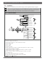
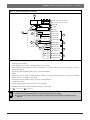
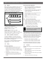
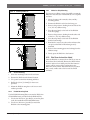
Some terminals are wired differently for the stand-alone (Figure 2) and slave applications (Figure 3 on page 9).
When you are using the D2071AC, mount the D4103R Enclosure and have a qualified electrician
connect a 110 VAC or 120 VAC power source to the black and white leads on the transformer.
Before beginning the D2071A installation, ensure the power source is turned off.
Figure 2: Stand-Alone Installation
S
P
1
12 VAC, 20 VA, 60 Hz
S
P
2
12 VAC, 20 VA, 60 Hz
3
EARTH GND
1
-
P
4
BATTERY –
+
P
5
BATTERY +
P
6
INITIATING A1 –
S
7
INITIATING A2 –
P
8
INITIATING B1 +
S
9
INITIATING B2 +
3
5
6
5
P
S
10
P
10
11
S
11
P
10
SUPERVISORY HI
S
11
SUPERVISORY LO
12
SUPERVISORY HI
13
TBL RELAY NC
C
14
TBL RELAY COM
NO
15
TBL RELAY NO
NC
16
ALARM RELAY NC
C
17
ALARM RELAY COM
NO
18
ALARM RELAY NO
P
11
1
2
3
4
5
6
7
8
4
8
9
10
2
11
NC
7
12
13
-
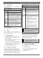
12 VAC, 20 VA transformer
Maximum charging current 300 mA
Battery backup (D126 [12 V, 7 Ah] or D1219 [12 V, 2.3 Ah])
Alarm initiating circuit
Open = Trouble
Short = Alarm
Supervisory circuits
Mode 3 (Alarm [short] = 0 VDC to 1.7 VDC; Normal [resistive] = 1.9 VDC to 5.8 VDC;
Trouble [open] = 6.0 VDC to 10.2 VDC)
9 - Mode 2 (Normal = 0 VDC to 1.5 VDC; Alarm [resistive] = 1.8 VDC to 9.0 VDC;
Trouble [open] = 9.3 VDC to 13.0 VDC)
10 - Mode 1 (Normal = 0 VDC to 1.5 VDC; Alarm [open] = 1.8 VDC to 13.0 VDC)
11 - 1.8 kΩ EOL resistor
12 - Phone Trouble Relay (maximum rating 2 A at 30 VDC)
13 - Initiating Circuit Alarm Relay (maximum rating 2A at 30 VDC)
Note:
8
= Power limited;
= Supervised
Bosch | 09/04 | 74-06200-000-F