1
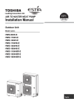
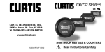
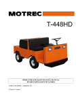
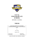
MODEL
M A N UA L
1604/1608
SWITCH MODE
BATTERY CHARGERS
for Lead-Acid Batteries
Before charging, read
instructions carefully!
IMPORTANT SAFETY INSTRUCTIONS
SAVE THESE INSTRUCTIONS
Read the Operating Instructions carefully before using the Model 1604 or Model 1608 charger.
1. WARNING – Failure to install and operate the charger in accordance with these instructions may result
in damage to the charger or injury to the operator.
2. WARNING – Never place the charger directly above or below the battery being charged. Gases or fluids
from the battery will corrode and damage the charger. Locate the charger as far away from the battery
as the output cable allows.
3. WARNING – Explosive gases may result from charging. Provide adequate ventilation during charging.
Prevent flames or sparks.
4. WARNING – Do not attempt to open the charger. There is risk of electric shock even if the charger is
unplugged. No user serviceable components inside.
5. WARNING – If safe operation of the charger can no longer be ensured, stop and secure it against
operation.
6. WARNING – If the supply cord is damaged, it must be replaced by a qualified person in order to avoid
hazard.
7. WARNING – Never charge a frozen battery.
8. WARNING – To reduce the risk of injury, charge only lead acid or gel cell type batteries. Do not attempt
to charge any other type of chargeable or non-rechargeable battery; these batteries may burst, causing
personal injury and damage.
9. CAUTION – It is recommended that you disconnect the AC power cord before connecting or disconnecting
the charger to the battery.
10. CAUTION – Not intended for outdoor use.
11. CAUTION – Charger surface may be hot while plugged in and for a period of time thereafter.
Handle unit by the cord to prevent scalding, or purchase optional handle kit P/N 17604348-3.
12. CAUTION – Units with fans must have at least 30mm of clearance on the vented ends of the charger.
Do not restrict ventilation to the charger in any way. Failure to do so may result in degradation of charge
performance.
13. CAUTION – If charger failure or malfunction may cause personal injury or material damage, use
additional safety measures such as limit switches, guards, etc.
14. CAUTION – Failure to install and use the charger in accordance with these instructions may impair the
protection provided by the charger and may void the manufacturers warranty.
15. CAUTION – Never plug a 120VAC only charger into a receptacle not rated for 120VAC nominal.
16. This charger was manufactured and tested according to the applicable technical standards referenced
herein. It complies with safety regulations as shipped from the factory.
17. This charger may be mounted to a machine by temporary means, such as Velcro®. However, this unit
was not designed to be permanently mounted to a machine.
18. Be sure to read and understand all of the battery manufacturer's instructions, such as removing or not
removing cell caps or recommended rate of charging, prior to using this charger.
19. Use of an adapter is not allowed in Canada. If a grounded-type receptacle is not available, do not use
this charger until a qualified electrician installs the proper outlet.
20. Extension cords used within the United States must be made of 18-3 cord with SP-2, SPE-2, SPT-2, SV,
SVE, SVT, or SJT flexible jacket material, a minimum length of 6 feet and a maximum length of 10
feet.
21. Extension cords in locations other than the United States should use cord made of 18-3 or 1.5 mm, 3
wire, with an appropriate jacket material; in Canada use type SJ or equivalent. Consult a qualified
electrician for details.
22. These chargers are suitable for use with rechargeable lead acid/gel cell batteries ONLY. 12VDC chargers are
suitable for use with 12VDC, 6-cell batteries ONLY. 24VDC chargers are suitable for use with 24VDC,
12-cell batteries ONLY. 4 amp chargers are intended for use with 10-40Ah batteries; 8 amp chargers are
intended for use with 26-80Ah batteries. 80% of these batteries’ capacity will be restored within 8 hours of
charging.
Warranty
Two Year Limited Warranty (see terms of sale for specifics).
All specifications subject to change without notice.
CONTENTS
1. MODEL ENCODEMENT.............................. page 1
2. TECHNICAL SPECIFICATIONS .................. page 2
3. INSTALLATION.............................................. page 4
4. OPERATION .................................................. page 5
5. TROUBLESHOOTING .................................. page 9
6. MAINTENANCE .......................................... page 9
MODEL ENCODEMENT
1
1
Model
Input
Voltage 2
/
12
Output
Series 4
/
04
Series
Number 5
1604CS
-
AVS
/
24
/
04
-
xxx
1604FV
-
AVS
/
12
/
08
-
xxx
-
AVS
/
24
/
08
-
xxx
-
AVS
/
12
/
08
-
xxx
-
AVS
/
24
/
08
-
xxx
1608FS
AVS
Output
Voltage 3
-
xxx
1
1604CS: Convection cooled, sealed to IP-54
1604FV: Fan cooled, protected to IP-31
1608FS: Fan cooled, electronics sealed to IP-54, fan protected to IP-31
2
AVS: Auto Voltage Select, operates at 120VAC or 230VAC automatically
3
12: 12VDC
24: 24VDC
4
04: 4A
08: 8A
5
Series Number: Identifies charger features, consult Curtis
Curtis 1604/08 Manual
page 1
TECHNICAL SPECIFICATIONS
2
2.1 Electrical
12V / 24V, 4A Chargers
120VAC
230VAC
90 - 132
180 - 264
Nominal Operating Voltage
Input Voltage (VAC)
Operating Frequency (Hz)
Input Current (A rms, max.)
12VDC nominal outputs
24VDC nominal outputs
Input Leakage
(µA, max.)
Output Power (W, nom./max.)
12VDC nominal outputs
24VDC nominal outputs
Output Current (A, max.)
Output Voltage (VDC, nom./range)
12VDC nominal outputs
24VDC nominal outputs
1.0 @
90V/60Hz
2.0 @
90V/60Hz
<500 @
120V/60Hz
0.5 @
180V/50Hz
1.0 @
180V/50Hz
<500 @
230V/50Hz
12V, 8A Chargers
120VAC
230VAC
90 - 132
180 - 264
47 - 63
24V, 8A Chargers
120VAC
230VAC
105 - 132
210 - 264
2.0 @
90V/60Hz
1.0 @
180V/50Hz
N/A
N/A
<500 @
120V/60Hz
<500 @
230V/50Hz
48 / 67.5
96 / 135
4.0
N/A
4.0 @
105V/60Hz
<500 @
120V/60Hz
N/A
2.0 @
210V/50Hz
<500 @
230V/50Hz
96 / 125
192 / 240
8.0
12 / 6.0 - 15.0
24 / 12.0 - 30.0
2.2 Mechanical
Case:
Aluminum alloy, black finish
End caps:
Polycarbonate, black
Dimensions (mm max.):
1604CS & 1604FV:
1608FS:
160 L x 96 W x 52 H
160 L x 140 W x 52 H
Weight (kg) 1604/1608:
1.0/1.5
2.3 Connections
AC Power Inlet:
IEC 320/C14 Male on cable
DC Power:
ITT Cannon XLR-3-12C Male Plug or equivalent on cable
Pin Function
1
B+
2
B3
Motor Controller Charging Indicator
Programming Port:
Molex 39-01-2040 with four female crimp terminals
(Molex 39-00-0056). Use with Curtis Model 1311 Hand
Held Programmer only.
Pin Function
1
Rx
2
SEC_RTN
3
Tx
4
+12V
Output Adapters:
P/N 17604348-1 for use with
Model 1288 Motor Controller
P/N 17604348-2 for use as
ISO-7176 compliant Off-board Charger
Function
Pin
Function
Motor Controller
1
B+
Charging Indicator
2
B2
B+
3
B- (inhibit)
3
N/C
4
N/C
5
B6
N/C
Charge Indicator: Low impedance capable of sinking 60 mA DC to B-.
Remote LED: Some models come with a wire harness for remote LED capability.
Contact your local Curtis sales office for details.
Pin
1
page 2
Curtis 1604/08 Manual
2.4 Environmental
Operating Range: -10˚C to + 50˚C
Storage Range:
-40˚C to + 85˚C
Humidity:
95% RH (non-condensing) at 35˚C
Shock:
SAE J1378, 55g
Vibration:
5g rms, 5-500 Hz, 2 hours per axis
Protection:
1604CS: IP54
1604FV: IP31 (horizontal mounting)
1608FV: IP54 (Electronics) IP31 (Fan)
2.5 Compliance
1604CS
UL 1012
CAN/CSA-C22.2 No.107.2
EN60335-1
EN60335-2-29
EN55011
EN61000-3-3
EN61000-4-2
EN61000-4-3
EN61000-4-4
EN61000-4-5
EN61000-4-6
EN61000-4-8
EN61000-4-11
ENV 50204
1604FV
UL 1012
CAN/CSA-C22.2 No.107.2
EN60335-1
EN60335-2-29
EN55011
EN61000-3-3
EN61000-4-2
EN61000-4-3
EN61000-4-4
EN61000-4-5
EN61000-4-6
EN61000-4-8
EN61000-4-11
ENV 50204
1608FS
UL1012
CAN/CSA-C22.2 No.107.2
EN60335-1
EN60335-2-29
EN55011
EN61000-3-3
EN61000-4-2
EN61000-4-3
EN61000-4-4
EN61000-4-5
EN61000-4-6
EN61000-4-8
EN61000-4-11
ENV 50204
2.6 Battery Types
All chargers are intended for use with lead acid or gel cell batteries only, for their
respective voltages.
2.7 Charge Cycle Profile
Models 1604 and 1608 use a multi-stage charge cycle, dependent upon battery
geometry, with software programmable set points.
1. Constant Current Mode: Output current is 4.0A max for the 4A models or
8.0A max for the 8A models. Current is held constant until the constant
voltage is reached. Output current is reduced during the Constant Current
Mode if the charger should begin to overheat.
2. Constant Voltage Mode: Output voltage shall be held at an average voltage of
approximately 14.3V for 12V chargers or 28.6V for 24V chargers. The charger
will hold the voltage to within 100mV of this value, reducing the current
gradually until the charging ends. Charging ends when the current falls below
0.5A or the charger remains in Constant Voltage Mode for more than 4 hours.
The charger will shut down and remain in standby.
Curtis 1604/08 Manual
page 3
3. Restart: If the battery self-discharges below 12.9V for 12V batteries or below
25.7V for 24V batteries while the charger is in standby, the charger cycles into a
constant current of 1.0A (4A models)/2.0A (8A models) until the constant
voltage setpoint is reached. The unit will regulate and terminate as in Constant
Voltage Mode.
2.8 Indication Lights
The charger features built in diagnostics. Refer to the table below to interpret the
flashing of the yellow and green indicator lights. Flashing of the yellow indicator
means that the charging cycle has ended early and the battery may not be fully
charged. Refer to the Troubleshooting section to correct these faults.
Flash Pattern
Yellow on
Green on
Green blinking
Yellow & Green on simultaneously
Yellow & Green blink simultaneously
Yellow blinks 1X
Yellow blinks 2X
Yellow blinks 3X
Yellow blinks 4X
Yellow blinks 5X
3
INSTALLATION
•
•
•
•
page 4
Indication
AC power present
Charge complete
Charging
Charger in standby mode
No battery/reverse polarity
Not reaching constant voltage setpoint
Not reaching 24V within 2 hours
Charge current/voltage does not normalize
Battery voltage too high (over 32V)
Charger over temperature
Charger should be securely mounted on a flat surface.
The power cord to the IEC 320/C14 connector should be of the appropriate
gauge to carry a 10A current @ 120VAC, or a 5A current @ 230VAC for
the cable’s length, to meet the requirements of applicable electrical codes.
A minimum of 30mm clearance should be provided at each end of the
charger for vented models.
The charger should not be installed in locations which restrict air flow.
Curtis 1604/08 Manual
OPERATION
4
4.1. Charging the Battery
Note: If a DC output adapter is used, connect the adapter to the charger output
connector prior to supplying AC power to the charger.
4.1.1 Ensure that the charger is either unplugged from AC power or is in
standby mode.
4.1.2 Connect the charger output connector to the vehicle/battery connector.
4.1.3 Plug the AC line cord into a nearby outlet. Turn on wall switch (if used).
The yellow light will illuminate to indicate that AC power is present.
After several seconds the green light will flash to indicate that charging is
in process. If no lights are illuminated, or if the yellow light flashes,
refer to the Troubleshooting section. Charge time may vary from less
than 1 hour to 10 hours.
4.1.4 When charging is complete both the yellow and green lights will remain
on and the charger will be in standby mode. The charger is now ready to
be disconnected from AC power or from the battery. Note: if the charger
is disconnected from the battery and connected to another battery with
out removing AC power it resets itself over a three minute period.
During this reset, the yellow light will flash briefly and the charger will
return to standby mode prior to beginning a charge cycle.
4.2. Programming the Charger
The Model 1604 or 1608 charger has a number of parameters that can be
programmed by the user, using a Curtis 1311 handheld programmer. These
programming variables allow the charger's performance characteristics to fit the
needs of the individual application. To use the 1311 refer to the 1311 instruction
manual, Curtis P/N 53028.
While programming can be performed when the charger is connected to the
batteries or when charging, it is recommended that the charger be disconnected
from power and from the batteries prior to commencing programming.
Connecting the programmer to the charger while charging will result in the
immediate termination of the charge cycle. The charger will remain in standby as
long as the programmer is connected.
There are two Program menu options - Basic Settings and Top Off Settings.
There are four options under the Basic Settings. They are described in the following
order. They are listed in the text by the names that appear on the programmer's
Program Menu: (bold text indicates default settings)
- Constant Voltage
- Amp hour Capacity
- End of Charge Mode
- Fan Modulation
Constant Voltage (CV, see figures 1, 2, 3 and 4)
Constant voltage defines the battery voltage at which point the charger changes
from constant current mode to constant voltage mode. Three Constant Voltage setpoints are available:
Option
Setpoint (VDC)
Battery Chemistry
12VDC charger 24VDC charger
1
2
3
Curtis 1604/08 Manual
14.0
14.3
14.6
28.0
28.6
29.2
Gel
AGM, Gel, SLA, VRLA
special applications as required by the
battery manufacturer
page 5
Amp hour Capacity
Amp hour Capacity is the storage capacity of the battery, as defined by the
battery's manufacturer. Selecting the appropriate amp hour capacity determines
the longest period of time the charger will charge before automatically shutting
off. If the charger is still charging at this point, it provides an error code to the
operator. Refer to Section 5, Troubleshooting, to correct this error. Three Amp
hour Capacity setpoints are available:
Option
Amp hour rating
Charge Cycle Timer (tc, see Fig. 1, 2, 3 and 4)
(4A / 8A charger)
(hours)
1
≤60 / ≤100
16
2
≤100 / ≤200
24
3
≤200 / ≤400
48
End of Charge Mode
End of Charge Mode defines how the charger terminates the charge cycle. There are
three End of Charge Modes:
Option
Mode
Notes
1
End of Charge Charge Profile: IVa
(see Figure 1)
Charger goes into standby upon reaching End of Charge
current. Charge will automatically restart if the standby
voltage falls below 12.9V (12V charger) 25.7V (24V charger),
and automatically self terminates. This compensates for battery
self-discharge over long periods of time. This mode is recommended
for daily use or for long term storage.
2
3
Equalize
Charge Profile: I1VI2a if previous mode was End of Charge
I1V1I2V2 if previous mode was Float.
(see Figure 2
and Figure 4)
After constant voltage terminates, charger adjusts its output
current to 1.5A/3A (4A/8A charger). The current is held
for either 3 hours or until the battery reaches 15.8V (12V
charger) or 30.5V (24V charger). The Equalize cycle automatically
reverts to the previous mode of charge termination after
the completion of 1 cycle. Check the battery manufacturer’s
recommendation regarding the frequency at which batteries
should be equalized.
Float
(see Figure 3)
Charge Profile: IV1V2
After constant voltage terminates, the charger reduces the
output current to 0.25A (24V charger), and cycles on and off
automatically to maintain an average battery voltage of (float
voltage, FV) 13.3V (12V charger) or 26.6VDC (24V charger).
This will continue until AC power is recycled. This mode of
charging is recommended for daily use or for short term
storage conditions to maintain battery health.
Fan Modulation - Default setting: Off
Fan Modulation can be turned on or off. If fan modulation is set to Off, the fan runs
at full speed whenever the charger is charging. This maximizes charger power output
over all operating conditions. If fan modulation is set to On, the speed of the fan is
proportional to the temperature of the charger. This mode of operation is quieter.
page 6
Curtis 1604/08 Manual
Top Off Settings - Default setting: Off
Charge profile with the Top Off settings enabled looks similar to the Equalize
end of charge mode (End of charge option 2). The difference is that in the Top
Off mode the following parameters can be adjusted:
- Top Off Time, ranging from 0 to 5 hours;
- Top Off Voltage, ranging from 28 to 32.4 Volts;
- Top Off Current, ranging from 0.5 to 4.5 Amperes.
The Top Off mode is enabled by setting the Top Off Time to a value higher
than zero. The charger enters the Top Off mode at the end of the main charge
cycle (after the constant voltage part) and sets the output current to the value
defined by the Top Off Current setting. The Top-Off mode will finish when:
(1) preset Top Off Time expires or (2) battery voltage reaches the Top Off
Voltage setting, whichever happens first.
At the end of the Top Off mode, the charger continues according to the End of
Charge Mode settings - stands by and awaits for the restart voltage or continues the float mode.
To program the charger:
Curtis chargers do not use the 1311's Monitor, Faults, or Functions Menus. The
Information and Programmer Setup Menus operate as describe in the 1311's
instruction manual with the exception of the Serial Number submenu in the
Information Menu – this field is filled with a default value of 12345678.
4.2.1. Disconnect the charger from the AC outlet and battery.
4.2.2. Attach the programmer to the 4-pin Molex connector on the charger
(near the light indicators). Depending on the specific 1311 being used,
a different connector cable may be required to connect to the charger.
Contact a Curtis sales office for assistance.
4.2.3. Apply AC power to the charger. The yellow and green light indicators
will alternately blink, indicating that the charger is in programming mode.
4.2.4. Configure the programmable parameters described above.
4.2.5. Once the programmable parameters have been defined, disconnect the
1311 programmer from the charger and follow the charger installation
instructions.
V/I
V
CV
C
I
tc
t
Figure 1. End of Charge Profile
Curtis 1604/08 Manual
page 7
V/I
V/I
V
CV
CV
FV
I
tc
t
t
Figure 2. End of Charge Profile with Equalize
V/I
V
CV
FV
CV
FV
I
t
tc
t
Figure 3. Float Profile
V/I
V
CV
FV
I
tc
t
Figure 4. Float Profile with Equalize
page 8
Curtis 1604/08 Manual
TROUBLESHOOTING
5
Problem
Possible Causes & Solutions
Lights do not turn on.
No power. Plug the unit in.
No power. If the outlet is damaged, try another
outlet on another circuit.
Yellow light blinks 1x
Battery manufacturer’s rated capacity may
exceed charger's rating.
Battery may be damaged or old.
Yellow light blinks 2x
Battery manufacturer’s rated capacity may
exceed charger's rating.
Battery may be damaged or old.
Yellow light blinks 3x
Battery manufacturer's rated capacity may
exceed charger's rating.
Battery may be damaged or old.
Unit may be damaged if operation does not
resume after AC power is removed and reapplied.
Yellow light blinks 4x
Battery voltage exceeds charger specified
operating range.
Yellow light blinks 5x
Charger overheated. Remove power, wait ten
minutes and then reapply power.
Yellow & Green lights
blink simultaneously
Battery may not be connected to the charger.
Battery may be severely discharged (<6VDC).
Battery connections may be reversed.
Yellow & Green lights
alternately blink
Charger is in the program mode. Handheld
programmer is connected to the charger.
Disconnect the programmer from the charger.
MAINTENANCE
6
Cleaning:
Excess dirt or grime may be removed from the unit by wiping it with a cloth
dampened with water.
Curtis 1604/08 Manual
page 9
CURTIS INSTRUMENTS, INC.
200 Kisco Avenue, Mt. Kisco, NY 10549 • Tel: (914) 666-2971 • FAX (914) 666-2188
www.curtisinst.com
is a registered trademark of Curtis Instruments, Inc.
Specifications subject to change without notice
© 2005 CURTIS INSTRUMENTS, INC.
53031 REV F 7/05