1
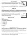
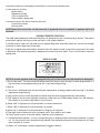
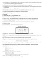
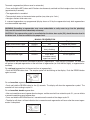
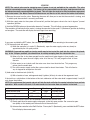
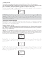
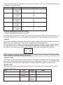
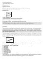
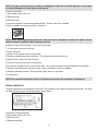
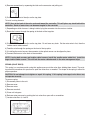
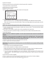
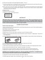
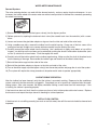
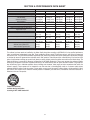
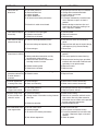
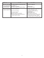
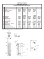
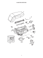
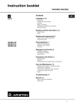
INSTALLATION AND OPERATING
INSTRUCTIONS
METERED WATER SOFTENERS
MODELS:
AWS100M
AWS150M
AWS200M
AWS250M
AWS300M
CAUTION: Damage to the system can occur (including possible
mineral tank structural failure resulting in a water leak), if system
is subjected to a vacuum. The installer should take appropriate
measures to prevent a vacuum. This would include the installation of an appropriate device in the supply line to the system, i.e.
a vacuum breaker or backflow protection device. Vacuum damage
voids the factory warranty.
®
a 3M company
(Installer: Please leave with homeowner)
IN300C 0606
CUNO Incorporated
400 Research Parkway
Meriden, CT 06450, U.S.A.
Toll Free: (800)222-7880
Worldwide: 203-237-5541
Fax: 203-238-8701
www.cuno.com
TABLE OF CONTENTS
SECTION
DESCRIPTION
1
2
3
4
5
6
7
8
BEFORE INSTALLATION
INSTALLATION
PROGRAMMING
SERVICE INSTRUCTIONS & MAINTENANCE
PERFORMANCE DATA SHEET
TROUBLESHOOTING
PARTS
WARRANTY
SECTION 1: BEFORE INSTALLATION
IMPORTANT: Read and follow all instructions before installation. Failure to do so may cause physical harm and/
or property damage. Failure to follow instructions may result in voidance of warranty.
ELECTRICAL
There are no user-serviceable parts in the AC adapter, motor, or controller. In the event of a failure, these should be replaced.
1) All electrical connections must be completed according to local codes.
2) Use only the power AC adapter that is supplied.
3) The power outlet must be grounded.
4) To disconnect power, unplug the AC adapter from its power source.
MECHANICAL
1) Do not use petroleum based lubricants such as vaseline, oils, or hydrocarbon based lubricants. Use only
100% silicone lubricants.
2) All plastic connections should be hand tightened. Thread tape may be used on connections that do not use
an o-ring seal. Do not use pliers or pipe wrenches.
3) All plumbing must be completed according to local codes.
4) Soldering near the drain line should be done before connecting the drain line to the valve. Excessive heat will
cause interior damage to the valve.
5) Observe drain line requirements.
6) Do not use lead-based solder for sweat solder connections.
7) The drain line must be a minimum of 1/2 inch diameter. Use 3/4 inch pipe if the backwash flow rate is greater
than 7 gpm (26.5 lpm) or the pipe length is greater than 20 ft (6 m).
8) Do not support the weight of the system on the control valve fittings, plumbing or the bypass.
9) It is not recommended to use sealants on the threads. Use thread tap on the threads of the 1 inch NPT elbow,
the drain line connections, and other NPT threads.
GENERAL
1) Observe all warnings that appear in this manual.
2) Keep the media tank in the upright position. Do not turn upside down or drop. Turning the tank upside down
will cause media to enter the valve.
3) Operating temperature is between 34°F (1°C) and 100°F (38°C).
4) Working water pressure range is 20 - 100 psi.
1-1
CAUTION: To reduce the risks associated with water leakage, which, if not avoided, may result in property
damage — check with your plumbing professional to verify that water pressure is less than 100 psi.
5) Use only regenerant salts designed for water softening.
6) Follow state and local codes for water testing.
IMPORTANT: Do not use with water that is microbiologically unsafe or of unknown quality without
adequate disinfection before or after the system.
7) When installing the water connections (bypass or manifold) connect to the plumbing system first. Allow heated
parts to cool and cemented parts to be set before installing any plastic parts. Do not get primer or solvent on
o-rings, nuts or the valve.
NOTE: If sediment is present, the installation of a sediment pre-filter is recommended. Even if sediment is not currently present or at a level high enough to be objectionable, a pre-filter can increase
the efficiency of the softener and reduce the amount of maintenance required.
LOCATION SELECTION
Location of a water treatment system is important. The following conditions are required:
1) Level platform or floor.
2) Room to access equipment for maintenance and adding regenerant (salt) to tank.
3) Temperatures over 34°F (1°C) and below 100°F (38°C).
4) Water pressure below 100 psi and above 20 psi.
5) Constant electrical supply to operate the controller.
6) Total minimum pipe run to water heater of 10 ft (3 m) to prevent backup of hot water into system.
7) Local drain for discharge as close as possible.
8) Water line connections with shut-off or bypass valves.
9) Must meet any local and state codes for site of installation.
10) Valve is designed for minor plumbing misalignments. Do not support weight of systems on the plumbing.
11) Be sure all soldered pipes are fully cooled before attaching plastic valve to the plumbing.
OUTDOOR LOCATIONS
When the water conditioning system is installed outdoors, several items must be considered.
1) Moisture — The valve and controller are rated for NEMA 3 locations. Falling water should not affect performance. The system is not designed to withstand extreme humidity or water spray from below. Examples are:
constant heavy mist, near corrosive environment, upwards spray from sprinkler.
2) Direct Sunlight — The materials used will fade or discolor over time in direct sunlight. The integrits of the materials will not degrade to cause system failures.
If it is necessary to locate the conditioner in direct sunlight, a protective outdoor cover over the valve and controller is necessary.
3) Temperature — Extreme hot or cold temperatures will cause damage to the valve or controller.
Freezing temperatures will freeze the water in the valve. This will cause physical damage to the internal parts
as well as the plumbing.
High temperatures will affect the controller. The display may be unreadable but the controller should continue
to function. When the temperature drops down into normal operating limits the display will return to normal.
A protective cover should assist with high temperature applications.
4) Insects — The controller and valve have been designed to keep all but the smallest insects out of the critical
areas. Any holes in the top plate can be covered with a metal foil ductwork tape. The top cover should be
installed securely in place.
5) Wind — The cover is designed to withstand a 30 mph (48 kph) wind when properly installed on the valve.
1-2
SECTION 2: INSTALLATION
WATER LINE CONNECTION
A bypass valve system should be installed on all water conditioning systems. Bypass valves isolate the conditioner from the water system and allow unconditioned water to be used. Service or routine maintenance procedures may also require that the system is bypassed.
CAUTION: The inlet water must be connected to the inlet port of the valve. When replacing other makes
of valves, the inlet and outlet may be reversed. It is also possible for the plumbing to be installed in an
opposite order. Do not solder pipes with lead-based solder.
CAUTION: Do not use tools to tighten plastic fittings. Over time, stress may break the connections.
When the bypass valve is used, only hand tighten the nuts.
CAUTION: Do not use petroleum grease on gaskets when connecting bypass plumbing. Use only 100%
silicone grease products. Non-silicone grease may cause plastic components to fail over time.
DRAIN LINE CONNECTION
NOTE: Standard commercial practices are expressed here. Local codes may require changes to the following suggestions. Check with local authorities before installing a system.
1) The unit should be above and not more than 20 ft (6.1 m) from the drain. Use an
appropriate adapter fitting to connect 1/2 inch (1.3 cm) plastic tubing to the drain
line connection of the control valve.
2) If the backwash flow rate exceeds 5 gpm (22.7 lpm) or if the unit is located 20 - 40
ft (6.1 - 12.2 m) from drain, use 3/4 inch (1.9 cm) tubing. Use appropriate fittings
to connect the 3/4 inch tubing to the 3/4 inch NPT drain connection on valve.
3) The drain line may be elevated up to 6 ft (1.8 m) providing the run does not exceed
15 ft (4.6 m) and water pressure at the conditioner is not less than 40 psi. Elevation can increase by 2 ft (61 cm) for each additional 10 psi of water pressure at
the drain connector.
Drain Line Connection
4) Where the drain line is elevated but empties into a drain below the level of the control valve, form a 7 inch (18
cm) loop at the far end of the line so that the bottom of the loop is level with the drain line connection. This will
provide an adequate siphon trap. Where the drain empties into an overhead sewer, a sink-type trap must be
used. Secure the end of the drain line to prevent it from moving.
CAUTION: Never insert drain line directly into a drain, sewer line or trap. Always allow an air gap between the drain line and the wastewater to prevent the possibility of sewage being back-siphoned into
the conditioner.
In the event of a malfunction, the BRINE TANK OVERFLOW will direct “overflow” to the drain instead of spilling
on the floor. This fitting is located on the side of the brine tank.
Do not elevate overflow line higher than overflow fitting.
Do not tie into drain line of control unit. Overflow line must be a direct, separate line from overflow fitting to drain,
sewer or tub. Allow an air gap as per drain line instructions.
2-1
BRINE LINE CONNECTION
The brine line to the brine tank connects to the valve. Make the connections and tighten.
Be sure that the brine line is secure and free from air leak. Even a small leak may cause
the brine line to drain out, and the conditioner will not draw brine from the tank. This may
also introduce air into the valve causing problems with valve operation.
ELECTRICAL CONNECTION
All AWS controllers operate on 12-volt alternating current power supply. This requires use of the supplied
AC adapter.
AC ADAPTERS
Make sure power source matches the rating printed on the AC adapter.
NOTE: The power source should be constant. Be certain the AC adapter is not on a switched outlet.
Power interruptions longer than 8 hours may cause the controller to lose the time and day settings.
When power is restored, the day and time settings must then be reentered.
CAMSHAFT
The front end of the camshaft has an indicator cup. The cup has slots in the outer
periphery and numbers on the inside face. The numbers can be seen with the cover
off, from the front over the top of the controller. The number at the top indicates which
regeneration cycle is currently in progress.
CAMSHAFT FRONT END
The corresponding slot for the number is positioned at the optical sensor which is approximately 90 degrees out
of phase.
Regeneration Cycle Indicators
C0 = Treated Water - normal operation mode
C1 = Backwash Cycle
C2 = Brine Draw Cycle
C3 = Slow Rinse Cycle
C4 = System Pause
C5 = Fast Rinse Cycle 1
C6 = Backwash Cycle 2
C7 = Fast Rinse Cycle 2
C8 = Brine Refill
POWER LOSS MEMORY RETENTION
The AWS series controllers feature battery-free time and date retention during the loss of power. This is designed to last a minimum of 8 hours depending on the installation. The controller will continue to keep time and
day in dynamic memory while there is no AC power.
The controller will not track water usage on volumetric demand controls in the event of a power failure.
All programmed parameters are stored in the static memory and will not be lost in the event of a power failure.
These settings are maintained separately from the time and day settings.
MOTOR
The controller uses a standard 12-volt AC motor that works with either 50 Hz or 60 Hz. The same motor is used
worldwide and does not need to be changed for different power conditions.
2-2
Information entered or calculated by the controller is stored in two different ways:
A static memory will store:
Media volume
Regenerant setting
Time of regeneration
Days between regeneration
A dynamic memory with 8 hour retention will store:
Current day of week
Running clock
NOTE: Water flow to the valve can be turned on or bypassed when the controller is powered up for the
first time.
VARIABLE RESERVE FUNCTION
The AWS metered-demand volumetric controllers are designed to have a variable reserve feature. This feature
automatically adjusts the reserve to the end-user’s water usage schedule.
A variable reserve saves salt and water by only regenerating when absolutely necessary, and ensures enough
soft water for typical high-water usage days.
Each day of regeneration the controller reviews the last four weeks of water usage for the same day of the week
to determine if the remaining capacity is adequate for the next day of the week. If not, it will initiate an automatic
regeneration.
DISPLAY ICONS
NOTE: In normal operation and during programming, only a few of the icons will actually be displayed.
1) Days of the week. The flag immediately below the day will appear when that day has been programmed as a
day the system should regenerated (used with 7-day timer programming).
2) See #3
3) This cursor is displayed when the days between regeneration are being programmed (used with .5 to 99 day
regeneration programming).
4) One of these cursors will be displayed to indicate which day will be programmed into the controller
5) “PM” indicates that the time displayed is between 12:00 noon and 12:00 midnight (there is no AM indicator).
PM indicator is not used if clock mode is set to 24-hour.
6) When “MIN” is displayed, the value entered is in minutes increments.
7) When “LBS” is displayed, the value entered is in pounds.
8) When “Kg” is displayed, the value entered is in kilograms or kilograins.
9) Four digits used to display the time or program value. Also used for error codes.
10) Colon flashes as part of the time display. Indicates normal operation.
11) Locked/unlocked indicator. In Level I programming this is displayed when the current parameter is lockedout. It is also used in Level II programming to indicate if the displayed parameter will be locked (icon will flash)
when controller is in Level I.
12) When “x2” is displayed, a second regeneration has been called for.
2-3
13) The recycle sign is displayed (flashing) when a regeneration at the next time of regeneration has been called
for. Also displayed (continuous) when in regeneration.
14) The display cursor is next to “SALT” when programming the amount of regenerant.
15) The display cursor is next to “REGEN TIME & DAY” when programming the time of regeneration and the days
of regeneration.
16) The display cursor is next to “TIME & DAY” when programming the current time and day.
17) The hourglass is displayed when the motor is running. The camshaft should be turning.
18) These cursors will appear next to the item that is currently displayed.
19) X100 multiplier for large values.
20) Not used.
21) Shows when water is flowing through the valve.
22) Used with #23, #24, #25. Displays a sequence number or a value.
23) History Values. The number displayed by #22 identifies which history value is currently displayed.
24) Parameter. Displayed only in Level II Programming. The number displayed by #22 identifies which
parameter is currently displayed.
25) Cycle. The number displayed by #22 is the current cycle in the regeneration sequence.
26) Hardness setting.
27) Capacity display — shows estimated system capacity.
KEYPAD - BUTTONS
1) DOWN arrow. Generally used to scroll down or increment through a group of choices.
2) SET. Used to accept a setting that normally becomes stored in memory. Also used together with the arrow
buttons.
3) UP arrow. Generally used to scroll up or increment through a group of choices.
4) Regenerate. Used to command the controller to regenerate. Also used to change the lock mode.
PROGRAMMING CONVENTIONS
The controller is programmed using the buttons on the keypad. The programming instructions will be described
two ways whenever a section has keypad input.
First, a table shows simplified instructions. Second, text follows that describes the action. In each table:
“Action” lists the event or action desired.
“Keys” are listed as:
UP for up arrow
DOWN for down arrow
SET for set
REGEN for regeneration
“Duration” describes how long a button is held down:
P/R for press and release
HOLD for press and hold
X sec for a number of seconds to press the button and hold it down
“Display” calls out the display icons that are visible.
2-4
REGENERATION MODES
The AWS series controllers can be regenerated either automatically or manually. During a regeneration, the total
time remaining of the regeneration, the total time remaining of the regeneration will be displayed on the controller.
The current cycle is shown in the lower left of the display.
Regeneration Cycle Indicators
C0 = Treated Water - normal operation mode (not displayed)
C1 = Backwash Cycle
C2 = Brine Draw Cycle
C3 = Slow Rinse Cycle
C4 = System Pause
C5 = Fast Rinse Cycle 1
C6 = Backwash Cycle 2
C7 = Fast Rinse Cycle 2
C8 = Brine Refill
Advancing the Regeneration Cycles
Action
Key
Duration
Display
Show current cycle
SET
HOLD
Cx
Show regen time remaining
SET
HOLD
Time
SET and UP
HOLD
Cx
Advance to next cycle
To advance cycles during a regeneration (manual or automatic):
• Press and hold the SET button. The current cycle number, (Ex. C1) will be displayed along with the time remaining for that individual cycle.
• When holding the SET button, simultaneously press the UP button, and release to advance to the next cycle.
While the motor is running, an hourglass icon will be displayed.
• Repeat this process for each cycle until the system is back into the treated water mode.
NOTE: When the controller gets to cycle C4 (Pause cycle), there may be a slight delay before the controller can
be advanced onto cycle C5.
NOTE: Not all regeneration cycles may be used. A cycle will be skipped if it is not requred by the current program.
Cancelling a Regeneration
Action
Cancel regen
Key
Duration
Display
SET and UP
5 sec.
Hourglass
starts to flash
2-5
To cancel a regeneration (either manual or automatic):
• Press and hold the SET button and UP buttons simultaneously and hold until the hourglass icon starts flashing
(approximately 5 seconds).
• The regeneration is cancelled.
• The camshaft rotates to the treated water position (may take up to 2 min.)
• Hourglass flashes while motor runs.
If a second regeneration was programmed (display shows a 2X by the regeneration icon) both regenerations
must be cancelled separately.
WARNING: Cancelling a regeneration may cause undesirable or salty water to go into the plumbing.
Only use this function when absolutely necessary.
CAUTION: If the regeneration cycle is cancelled after the brine draw cycle (C2), check the water level in
the brine tank. It must be refilled to the proper level.
MANUAL REGENERATION
Action
Regen at next time of regen
Key
REGEN
Duration
P/R
Display
Recycle icon flashes
Cancel regen
REGEN
P/R when recycle
Recycle icon disappears
icon is flashing
Immediate regen
REGEN
5 sec.
Recycle icon appears
Immediate double regen
REGEN
5 sec. when
immediate manual
regen has started
X2 icon appears
The controller can be manually instructed to perform a regeneration. There are two (2) choices: The controller
will perform a delayed regeneration at the next time of regeneration (ex. 2:00 AM that night), or regenerate immediately.
For a delayed regeneration (at the next set time of regeneration):
• Push the REGEN button once. The recycle symbol will be flashing on the display. Push the REGEN button
again to cancel.
For an immediate regeneration:
• Push and hold the REGEN button for five (5) seconds. The display will show the regeneration symbol. The
camshaft will start rotating to cycle C1.
For an immediate, double regeneration:
• After an immediate manual regeneration has begun, and the camshaft has rotated to cycle C1, you can initiate
a second immediate manual regeneration.
• Press and hold the REGEN button for 5 seconds once the camshaft has begun cycle C1.
• The display will show a x2 icon indication that a second manual regeneration will occur after the current regeneration is completed.
2-6
STARTUP
NOTE: The control valve can be started-up even if power is not yet available to the controller. The valve
must be connected to water supply. The motor can be unmounted from the valve, and the camshaft can
be indexed manually counterclockwise by hand. This will allow the tank to be filled and allows regenerant
draw to be tested. See Motor Removal in Maintenance and Service of this manual for further instructions.
1) Remove the cover from the valve. Removing the cover will allow you to see that the camshaft is turning, and
in which cycle the camshaft is currently positioned.
2) With the supply water for the system still turned off, position the bypass valve to the “not in bypass” (normal
operation) position.
3) Hold the REGEN button on the controller down for 5 seconds. This will initiate a manual regeneration.
The controller will indicate that the motor is turning the camshaft to the cycle C1 (Backwash) position by flashing
an hourglass. The controller will display the total regen time remaining.
If you press and hold the SET button, the controller will indicate the time remaining in the current cycle.
4) Fill the media tank with water.
A) While the controller is in cycle C1 (Backwash), open the water supply valve very slowly to
approximately the 1/4 open position
WARNING: If opened too rapidly or too far, media may be lost out of the tank into the valve or the plumbing. In the 1/4 open position, you should hear air slowly escaping from the valve drain line.
B) When all of the air has been purged from the media tank (water begins to flow steadily from
the drainline), open the main supply valve all of the way. This will purge the final air from
the tank.
C) Allow water to run to drain until the water runs clear from the drain line. This purges any
refuse from the media bed.
D) Turn off the water supply and let the system stand for about five minutes. This will allow for
any air trapped to escape from the tank.
5) Add water to the brine tank (initial fill).
A) With a bucket or hose, add approximately 2 gallons (8 liters) of water to the regenerant tank.
If the tank has a salt platform in the bottom of the tank, add water until the water level is approximately 1 inch (25
mm) above the platform.
NOTE: We recommend that you do not put salt into the tank until after the control valve has been put into
operation. With no salt in the tank, it is much easier to view water flow and motion in the tank.
Action
Key
Duration
Display
Display current cycle
SET
5 Sec
Current Cycle
Advance to next cycle
SET and UP
P/R
Next Cycle
Advance to CO
SET and UP
5 Sec
CO
6) Engage the refill cycle to prime the line between the brine tank and the valve.
A) Slowly open the main water supply valve again, to the fully open position. Be sure not to open
too rapidly as that would push the media out of the media tank.
B) Advance the controller to the Refill Position. From cycle C1 (Backwash), press and hold the SET button.
This will display the current cycle.
2-7
While pressing the SET button, press the UP arrow to advance to the next cycle. Continue to advance through
each cycle until you have reached cycle C8 (Refill).
NOTE: As you advance through each cycle there will be a slight delay before you can advance to the next
cycle. The hourglass icon will light while the camshaft is indexing. There may be a puase at cycle C4 (System Pause). This cycle allows the water/air pressure to equalize on each side of the valve discs before
moving on. The hourglass will not be visible indicating that the system is paused.
C) With the water supply completely open, when you arrive at cycle C8 (Refill), the controller will direct
water down through the line to the brine tank. let the water flow through the line until all air bubbles
have been purged from the line.
D) Do not let the water flow down the line to the tank for more than one to two minutes, or the
tank may overfill.
E) Once the air is purged from the line, press the SET button and the UP button simultaneously to
advance to cycle C0 (Treated Water) position.
7) Draw water from the brine tank.
Action
Key
Duration
Display
Advance to C1
REGEN
5 Sec
REGEN icon steady, C1
and time remaining
Advance to C2
SET and UP
P/R
REGEN icon steady, C2
and time remaining.
A) From the treated water position (cycle C0), advance the valve to the brine draw position. Hold the
REGEN button down for 5 seconds.
The controller will begin a manual regen, and advance the control valve to the cycle C1 (Backwash).
Press the SET and UP button to advance to cycle C2 (Draw).
B) With the controller in this position, check to see that the water in the brine tank is being drawn out of the
tank. The water level in the tank should recede very slowly.
C) Observe the water being drawn from the tank for at least three minutes. If the water level does not
recede, or goes up, reference the Troubleshooting section.
8) If the water level is receding from the tank you can then advance the controller back to the treated water (C0)
position by pressing SET and the UP buttons simultaneously to advance the controller to the C0 position.
9) Before loading salt add enough water back to the brine tank to cover the salt grid by approximately one (1) inch.
Then add initial salt fill to brine tank, and one cup full of unscented laundry bleach to the brine well.
10) Put softener through a complete regeneration - to sanitize the system before use (refer to previous section for
instructions on manual regeneration).
11) Finally, after the regeneration is complete, turn on a faucet plumbed after the water conditioner. Run the faucet
until the water runs clear.
Installation is now complete, and your water softener is now ready for service!
2-8
SECTION 3: PROGRAMMING
THINGS YOU MIGHT NEED TO KNOW
• When the controller is first plugged in, it may display a flashing hourglass and the message Err 3, this means
that the controller is rotating to the home position. If the Err 2 is displayed, check that the incoming power frequency matches the controller. See the Troubleshooting section of this manual.
• The preset default time of regeneration is 2:00 AM. If you want to change it, see the Level II Programming section.
• The controller can be programmed to regenerate on specific days of the week. See Level II Programming section.
• If electrical power is not available, the camshaft can be rotated to the left by hand if the motor is removed. See
Motor Removal in the Maintenance section.
• The controller sends commands to the motor for camshaft movement. However, water pressure/flow are required during the regeneration cycle for backwash, purge and refill, and brine draw to actually take place.
• Make sure control power source is plugged in. The transformer should be connected to a non-switched
power source.
PROGRAMMING
The controller is designed to operate by only setting the time of day and the day of the week. The remaining settings have been set at the factory. These default settings will work for most applications.
The controller menu has three levels:
Level I Basic — This level is easily accessed by the user. The settings can be changed and saved as long as
they are not locked.
Level II Professional — This level allows the installer to lock settings. The locked settings are viewable in the
basic level but cannot be changed.
History Level — The operation history and the program are viewable. This information is used to troubleshoot
and maintain the system.
BASIC PROGRAMMING
NOTE: If a button is not pushed for thirty seconds, the controller returns to normal operation mode.
Pushing the regenerate button immediately returns the controller to normal operation.
NOTE: Any setting that is a time display will not show “AM” for times between 12:00 midnight and 12:00
noon. “PM” is displayed to the right of the time for times between 12:00 noon and 12:00 midnight. When
using the 24 hour clock “PM” is not displayed.
3-1
To change a setting:
Action
Key
Duration
Display
Enter basic programming
SET
P/R
Will show day of week
UP and DOWN
P/R
Will increment through
Move to desired display
Enable setting to be changed
Change setting
Save setting
Return to operation
arrows
SET
UP and DOWN
arrows
SET
REGEN
P/R
P/R
P/R
P/R
the displays
Display will flash
Value changes and
continues to flash
Display stops flashing
Normal operation display
This level of programming is accessible by pressing the SET button.
The UP and DOWN arrows will step through the settings.
Time of day
Day of week
Time of regeneration
Number of days between regeneration (99 day calendar override timer)
Amount of salt used per regeneration
System capacity
Hardness
To make changes:
• Time of day
When the Time of Day is displayed, push SET. The time will flash. Use the arrow buttons to increase/decrease
the time. Push SET to enter the selection.
• Days of the week
The day of the week does not have a default setting. It is entered at Power-up. To change the current day, push
SET when day of week is displayed. A flag will flash beneath the current day. Use the arrow buttons to change.
Push SET to enter the selection.
• Time of Regeneration
This is set for 2:00 AM as the default. The controller does not account for daylight savings time.
To change this setting, push SET. Use the arrow buttons to increase/decrease the time. Push SET to enter the
selection.
3-2
• Calendar override
The controller can be programmed to regenerate automatically from a 1/2 day to a 99 day frequency.
The 1/2 day regeneration mode will regenerate at the “time of regeneration,” as well as 12 hours opposite from that
time. For example, the controller will regenerate at 2:00 AM and at 2:00 PM on the same day.
The default setting is 12 days. To change, push SET when this setting is displayed. Use the arrow buttons to
increase/decrease. Push SET to enter the selection.
CAUTION: Setting days between regeneration to zero will cause the system to not regenerate. This setting
is used for selecting regeneration on specific days or to use with a remote regeneration input. See below.
NOTE: Regeneration on specific day is used to provide regeneration when water demands are not steady.
Example: If the weekdays have low usage and the weekend is high, then regeneration every three days
will not meet the requirements.
• Amount of salt used per regeneration
The controllers are setup to automatically calculate the capacity of the system by multiplying the resin/media
volume that was entered earlier into the controller, with the salt amount entered by the dealer/installer. This
eliminates the need for salting efficiency tables.
The default setting is L (Low Salt).
To enable the most simple programming possible, the dealer/installer has three salt amount options to choose
from. These are set up to give the installation the maximum performance based on the inputs by the dealer/installer. The three salt options are:
High Salt — This setting gives the installation the highest capacity possible for that resin volume. This is a great
setting for applications with very high hardness, many occupants or for applications where the dealer wants to
provide that the application supplies soft water. This setting may tend to use less water over the course of a year,
because it generally needs to be regenerated less often. This setting is displayed as an “H”.
Standard Salt — This setting fits most applications around the world. It gives you an efficient use of salt, while
maintaining a large enough capacity to regenerate every three days for most applications. This setting is displayed as an “S”.
Low Salt — This setting is provided to give your installation the maximum efficiency of salt usage, as measured
in grains of hardness softened per pound of salt used (grains of CaCo3 reduced per pound of salt used). This
setting is useful for markets where highly efficient conditioners are expected or required by the consumers or law.
This setting is displayed as an “L”.
3-3
The following tables show the estimated salt amount for each setting, as well as the estimated capacity of that
salt setting for each resin amount.
Media Volume
1.0
1.5
2.0
2.5
3.0
Salt Setting
L (Low)
S (Standard)
H (High)
L (Low)
S (Standard)
H (High)
L (Low)
S (Standard)
H (High)
L (Low)
S (Standard)
H (High)
L (Low)
S (Standard)
H (High)
Total Salt Amount per Regeneration (lbs)
3.5
9
15
5
13.5
22.5
6.5
18
30
6.5
18
30
10
27
45
L = Low salt, approximately 3.3 lbs. per cu. ft. of media
S = Standard salt, approximately 9 lbs. per cu. ft. of media
H = High salt, approximately 15 lbs. per cu. ft. of media
To program the salt amount, press the SET button to enter the change mode. The L default will begin to flash. Use
the UP and DOWN arrow keys to scroll through the three settings. Press the SET button to enter the amount.
• Capacity
The controller is designed to estimate capacity of the system by multiplying the initial resin/media volume by the
regenerant amount programmed in under “Amount of regenerant used per regeneration.”
An estimated total system capacity is displayed in kilograins (kilograms CaCO3) that could be removed by the
fully regenerated media bed. This value is derived by standard water treatment industry norms. The system capacity is displayed merely for the installers reference when determining regeneration frequency.
NOTE: Capacity is the result of the amount of media in the tank and the salt setting. The default capacity
will be changed by selecting a different salt setting.
• Hardness setting
The hardness setting is set in grains per gallon (CaCO3). The hardness is divided into the total capacity setting,
giving a total volume of water that can be conditioned before a regeneration is needed. To set, press SET when
P8 is displayed, and use the UP or DOWN buttons to increment. Press SET again to accept the setting.
HISTORY LEVEL
This level displays settings and usage information that can be used to diagnose and troubleshoot the system.
To enter the history level:
Action
Enter data mode
Scroll through history
Reset value to factory default
Key
DOWN arrow
and SET
UP and DOWN
arrows P/R
SET
Duration
5 sec.
Display
Value for H0
P/R
Next history value
5 secs. with
value is
displayed
Original factory default
3-4
History Data
Description
Range
H0
Resin volume initial setting value
cubic feet
H1
Days since last regeneration
H2
Current flow rate
H3
Water used today in gallons since Time of Regeneration
0-65536 gallons
H4
Water used since last regeneration in gallons
0-65536 gallons
H5
Total water used since reset in 100s
0-65536 gallons
H6
Total water used since reset in 1,000,000
0-65536 gallons
H7
Average usage for Sunday in gallons
0-65536 gallons
H8
Average usage for Monday in gallons
0-65536 gallons
H9
Average usage for Tuesday in gallons
0-65536 gallons
H10
Average usage for Wednesday in gallons
0-65536 gallons
H11
Average usage for Thursday in gallons
0-65536 gallons
H12
Average usage for Friday in gallons
0-65536 gallons
H13
Average usage for Saturday in gallons
0-65536 gallons
0-255
0-47 gpm
When in history values mode a small “H” will be displayed in the lower left corner of the display. Next to the “H”
will be the number that applies to the history value.
H0 — System Resin Volume Setting
The history value H0 displays the initial resin volume setting (programmed when the system was first set up). If
the value is incorrect and needs to be reset, press and hold the SET button for five seconds to reset the controller.
CAUTION: Resetting the resin volume resets the entire controller back to the factory default. Only use
if absolutely necessary. The control will need to be completely reprogrammed.
3-5
IMPORTANT: SECTION 4: SERVICE INSTRUCTIONS & MAINTENANCE
VALVE SERVICE
COVER
The cover provides protection for the controller, wiring, and other components. This cover will be removed for
most service and maintenacnce.
When installed, the cover provides NEMA 3 water protection. This protects from falling water up to 30 degrees
from vertical.
To remove cover:
1) Grasp side edges toward rear of the valve.
2) Pull outwards until the slots in the cover clears the projections on the top plate.
3) Lift up on the rear and pull forward to clear the control module.
To install cover:
1) Position cover to be low in front and under the bottom edge of the control module.
2) The cover will hook on the bottom of the controller and drop down over the camshaft.
3) To finish, grasp the side edges and pull outward to clear the projections on the top plate.
4) Drop down until the cover snaps in place.
ELECTRONIC CONTROL MODULE
The purpose of the electronic control module is to control the regeneration cycle. The control module has several variations. When replacing the controller, use the same model or some functions may not work. This is an
electronic controller that is programmable and uses input/output signals.
To remove control module:
1) Disconnect power to the unit.
2) Remove valve cover.
3) Press trip lever to release module from top plate.
4) Pivot the top forward and up.
5) Remove any wire connections. Wire connections have a locking tab that must be squeezed before
removing.
NOTE: There is no need to label the wires. The keyed connectors will only plug back into one site.
To install control module:
1) Be sure the power is disconnected.
2) Check model.
4-1
3) Check routing of wires and plug them into the controller. Connectors will snap in place. Be sure that wires are
properly managed through the clips on top plate. This will prevent the wires from being caught in the camshaft.
4) Place bottom of module in position. The bottom will fit into a clip.
5) Pivot the top into position and snap in place. The controller should be secure.
If you are ready to program the controller, then power can be applied by plugging in transformer.
DRIVE MOTOR
The drive motor is open loop and receives commands from the control module. The motor has a pinion gear that
meshes with the camshaft gear to drive (rotate) the camshaft.
During operation, rotation forces the motor into its mounting position and screws or bolts are not needed.
NOTE: Some units will have a shipping peg in the top motor mount. The peg can be removed and discarded. This peg is not required for motor operation.
To remove motor:
1) Disconnect power to the unit.
2) Remove cover.
3) Pull off wiring connector.
4) Grasp the motor body and rotate to the left.
5) Pull motor out.
To install motor:
1) Insert gear through hole on top plate
2) With motor ears flat to the rear of the top plate, rotate to the right until mounting tabs are engaged in slots.
3) Reconnect wires.
NOTE: It is not necessary to pre-position the camshaft or the motor. When the controller is powered up
the camshaft will be rotated to the “home” position.
OPTICAL SENSOR
The optical sensor is mounted to the top plate. The camshaft cup rotates through the sensor and the slots are
detected. A signal is sent to the controller for each slot.
NOTE: Damaged sensors should be replaced. Sensors may be cleaned with compressed air or a soft brush.
4-2
To remove optical sensor:
1) Disconnect power to the unit.
2) Remove cover.
3) Remove controller.
4) From the controller side, pinch the legs of the sensor holder in the top plate.
5) Pull the holder away from the mounting surface.
6) Remove wires.
To install optical sensor:
1) Attach wires. Wires should point away from camshaft.
2) Place leading edge of sensor holder into opening.
3) Pivot holder into place. legs should enter slots and snap in place.
CAUTION: The optical sensor legs are fragile and may break. If the optical sensor legs break or crack, we
recommend replacement. A damaged sensor may result in improper regeneration.
CAMSHAFT
The camshaft has several lobes that push open the valve discs as the camshaft rotates. Rotation is controlled by
a drive motor that drives a gear at the rear of the camshaft. The front end has a cup with markings and slots.
CAUTION: The camshaft slots are molded to exact dimensions. Do not attempt to modify the cam cup
slots. Improper regen will occur!
The outside surface of the cup has an arrow mark. When the arrow is at top center, the camshaft is in the loading position. 90 degrees to the right on the cup an optical sensor is mounted to the top plate. This sensor reads
the slots as they pass through. The largest slot is “Home” and the remaining slots are positioned to signal the
regeneration cycles.
When looking at the end of the camshaft, numbers are visible in the hollow of the cup. An arrow on the top plate
points to the current marking. The numbers represent regeneration cycles as follows:
C0 = Treated water - normal operation mode
C1 = Backwash
C2 = Brine draw
C3 = Slow Rinse
C4 = System pause
C5 = Fast rinse cycle 1
C6 = Backwash cycle 2
C7 = Fast rinse cycle 2
C8 = Brine refill
These numbers are offset rotationally 90 degrees from the matching slot. The offset enable the service person
to view the number at the top of the cup and determine which slot is at the optical sensor.
4-3
NOTE: If any part of the camshaft is broken or damaged the camshaft should be replaced. Do not repair
or modify damaged cam lobes, gears or timing cup.
To remove camshaft:
1) Disconnect power to the unit.
2) Remove cover.
3) Remove motor.
4) Camshaft should be in the treated water position. Rotate to the left as needed.
5) Use a screwdriver to hold open the #1 valve disc.
NOTE: When replacing/removing camshaft, make sure not to damage or misalign the optical sensor.
Hold the sensor in position while removing camshaft.
6) Move the camshaft backwards, away from the controller.
7) Lift the loose front end up and out.
To install camshaft:
1) Check that the optical sensor is in position.
2) Position camshaft above the valve discs. The arrow on the cup should be up.
3) Slide the rear of the camshaft into place.
4) Pivot the camshaft close to its final position.
The camshaft will push on one or more valve discs. You will feel resistance as you complete the installation.
5) Move the camshaft down and into position. Force valve discs to move as needed.
6) Move the camshaft forward. Check that the optical sensor is in position.
7) Install motor.
NOTE: The camshaft will position itself to C0 (treated water) when the controller is powered up.
WIRING HARNESSES
The wiring harnesses are designed to fit one way. The connectors are unique to the port they plug into. The wires
are held in place by clips and the connectors latch in place.
To remove a wiring harnesses:
1) Disconnect power to the unit.
2) Remove cover.
3) Remove controller.
4-4
4) Remove connections by squeezing the latch on the connector and pulling out.
5) Pull the harness out of the clips on the top plate.
To install a wiring harness:
NOTE: Start at the back of the valve and work toward the controller. This will place any slack behind the
controller. Slack or loose wires can become tangled in the camshaft.
1) Depending on which harness is being installed, plug the connector into the motor or turbine.
2) Route the harness through the opeing at the back of the top plate.
3) Place the harness into the clips on the top plate. Do not leave any slack. Put the motor wire in first, then the
turbine sensor cable second.
4) Feed the wire through the opeing on the front of the top plate.
5) If installing the motor harness the connector to the optical sensor can be clipped in place.
6) Connect the harness to the back of the controller.
NOTE: If using both a motor and turbine cable harness, install the smaller motor cable first. Install the
larger turbine cable second. This will lock the motor cable beneath in the wire management clips.
SPRING (VALVE DISCS)
This spring is a one-piece metal spring that applies pressure to the valve discs holding them closed. The rotating camshaft overcomes this pressure to open the valve discs as needed. The shape of the spring is critical for
proper operation.
CAUTION: Do not attempt to straighten or repair this spring. If this spring is damaged, valve discs may
not operate correctly.
To remove spring:
1) Disconnect power to the unit.
2) Remove cover.
3) Remove motor.
4) Remove camshaft.
5) Place unit in bypass.
6) Release water pressure by pushing the last valve discs open with a screwdriver.
7) Locate valve discs 3, 4 and 5.
4-5
8) Position yourself on the spring side of the valve discs.
9) Place two (or more) fingers on the flat part of the spring.
10) Move the fingers toward the valve discs and into the spring valley between the previously located valve
discs.
11) By pulling back and up on the spring, the spring will pop out of the valley.
12) Pull back further to remove the spring.
To install spring:
1) Inspect the spring for damage. Do not attempt to repair a bent spring.
2) Position yourself on the spring side of the valve discs.
3) Position the spring over the valve body close to final position. The wide spring segments will be located at the
wide valve discs. The curve of the spring will be down into the valve.
The long flat close edge is inserted first. This edge slides into a channel on the valve body.
The spring will slide off the top of the valve disc downward. The small projection on the end of the spring will drop
into the hole in the valve disc to provide secure positioning. Repeat for all spring segments.
NOTE: If a spring segment goes beyond the locating hole, it can be pulled back using a small flat blade
screwdriver.
NOTE: In high pressure (80 psi and higher) applications, the standard single valve disc springs can be
installed on top of the one piece spring.
4) Rock the spring back and place the flat edge into the channel.
5) Lower the springs until they rest on top of the valve discs.
A tool (phillips screwdriver) will be needed to push the springs in place.
The spring posts will guide the spring into place.
6) Hold the flat part down with one hand.
7) Spread your fingers apart to cover the length and push down.
8) With the other hand use the tool to push down in the valley of each spring segment.
TOP PLATE
The top plate holds the valve discs in place during operation. This plate is removed to allow cleaning and replaing the valve discs.
NOTE: The valve discs are made from a chloramine resistant severe service rubber. The valve discs will
usually not need to be changed. Before removing the top plate for valve disc service be certain that one
of the discs is not operating correctly.
To remove top plate:
1) Disconnect power to unit.
2) Remove cover.
3) Remove motor.
4) Remove camshaft.
4-6
5) Place unit in bypass.
6) Release water pressure by pushing the last valve disc open with a screwdriver.
7) Any optional items may be removed.
8) Wiring harnesses should be removed.
9) Remove valve disc spring.
10) Use a phillips screwdriver to remove the screws from the top plate.
11) Lift the top plate off. All the valve discs can be pulled straight out.
Inspect valve discs for wear. The sealing surface is the raised ridge on the underside of the top shoulder.
Check each valve disc cavity in the valve for debris. Remove any foreign objects before replacing the valve disc.
To install valve discs:
NOTE: If the valve disc fits properly in the cavity, it will work correctly.
1) Put the valve disc into the correct (based on shoulder size) valve port cavity. The metal end without rubber
coating should be visible.
2) Push down on the shoulder to position the valve disc completely into the port cavity.
The metal portion will be positioned straight up and the top of the shoulder will be level with the valve.
To install the top plate:
NOTE: All valve discs should be in position. Use the same screws that were removed to reassemble the
top plate.
IMPORTANT: Follow the procedure to engage the screws with the existing threads. If the same threads
are not used, the holding power of the screw is lost. Under pressure the valve can leak. Screws that have
the same diameter but have different threads should not be used.
1) Position the top plate on top of the valve and over the valve discs.
2) Insert a screw at one of the corner positions.
IMPORTANT: This procedure for reinserting screws must be followed to ensure proper holding strength
of the screws.
A. Drop screw of same size and thread into the hole.
B. Use a phillips screwdriver and lightly rotate the screw backwards
C. When the thread of the screw and thread of the hole match, the screw will “click” and slightly drop down.
D. The threads are lines up. Lightly rotate the screw to tighten and engage threads.
E. Once the threads have engaged the screw can be tightened. Minimal resistance will be present as the
screw is turned in. Resistance indicates new threads are being formed. Back the screw out and rematch
the threads.
3) Turn the screw in but do not tighten.
4) Place a second screw into the hole disagonally opposite the first screw and turn in but do not tighten.
5) Insert another screw into one of the remaining corners and turn it in.
4-7
6) The fourth screw goes into the hole diagonally opposite. Turn it in.
7) Put the remaining screws in following the same crisscross pattern working from the ends toward the center.
When all the screws are in place they can be tightened down.
8) Start at the corner of the screw pattern and tighten that screw. Work the same pattern from the ends toward
the center and crisscrossing as each screw is tightened. Check that each valve disc moves smoothly before
replacing the spring and camshaft.
9) Replace spring.
10) Replace camshaft and motor.
11) Replace controller and wiring harnesses.
MAINTENANCE
IMPORTANT: Many of the maintenance procedures involve o-rings. When reassembling two parts with
an o-ring seal, care must be taken with the placement of the o-ring. To properly install o-rings, they
should be lightly lubricated with silicone. Place the o-ring over the part feature that will be inserted into
the hole. Do not start the assembly with the o-ring in the hole.
PREVENTIVE MAINTENANCE
Injector Screen and Injector
Inspect and clean brine tank and screen filter on end of brine pickup tube once a year or when sediment appears
in the bottom of the brine tank.
Clean injector screen and injector once a year.
1) Unplug the wall-mount transformer.
2) Remove cover. Shut off water supply or put bypass valve(s) into bypass position.
3) Relieve system and valve pressure by using a screwdriver to press valve disc #7 slightly open. The pressure
will escape quickly.
4) Using a T-50 torx driver (recommended), or large flat blade screwdriver, remove injector screen and injector cap.
5) Clean injector screen using a fine brush. Flush under running water until clean.
6) Using a needle-nose pliers, pull injector straight out.
7) Flush water into the injector screen recess of the valve body to flush debris out through the injector recess.
8) Clean and flush the injector with water. Inspect for any debris in the venturi.
9) Lubricate the o-rings on the injector, injector cap and injector screen with silicone lubricant only!
10) Reinstall the injector, injector cap and injector screen. Be careful not to crimp or bend the o-rings.
CAUTION: Do not overtighten the plastic cap. Seat the cap lightly into position. Overtightening may
cause breakage of the plastic cap that may not be immediately evident.
11) Plug the wall-mount transformer into outlet; reset clock if necessary.
12) Slowly open water supply valve or return bypass valve(s) to the “service” position.
4-8
WATER METER MAINTENANCE
Demand Systems
The valve metering devices are used with the demand controls, and may require simple maintenance. In rare
instances, the turbine wheel of the water meter can collect small particles of oxidized iron, eventually preventing
the wheel from turning.
1) Shut off the water supply or put the bypass valve(s) into the bypass position.
2) Relieve pressure by opening the backwash drain valve (the seventh back from the controller) with a screwdriver.
3) Loosen and remove the pipe/tube adapters or bypass from the inlet and outlet of the valve body.
4) Using a needle-nose pliers, remove the turbine from the outlet housing. Grasp one of the four vanes of the
outer gland and pull straight out to remove turbine assembly from the outlet of the valve.
5) Carefully remove the turbine wheel from the housing. Use a toothbrush to lightly scrub debris or iron off the
magnet. Iron build-up on the surfaces can be reduced by soaking the wheel in mild sodium hydrosulfite (such
as Iron-X) solution for a few minutes. Flush thoroughly with water.
6) Carefully reinstall the turbine wheel into the turbine cage housing. Make sure that the shaft of the wheel seats
into the bearing of the cage. Reassemble the turbine cage and check that the wheel rotates freely.
7) Reinstall the turbine cage into the outlet of the valve.
8) Reinstall the pipe/tube adapters or bypass to the inlet and outlet of the valve.
9) Turn on the water supply or put the bypass valve(s) into the service position and purge the air out of the system.
10) The system will require the statup procedure to be performed in order to operate appropriately.
CHECK TURBINE OPERATION
After the turbine has been cleaned, verify that the turbine is accurately working. Repressurize the conditioner
system, and verify that the controller is plugged in. Completely turn on a faucet that is plumbed after the conditioning system. After a few seconds, the display should be flashing a small faucet icon with water drops. If this
is flashing, the turbine is operating properly.
If the faucet icon does not flash, then the system may have a faulty turbine probe cable wire harness. Replace
that harnesss and repeat the steps above for checking for turbine operation.
REFILL FLOW CONTROL
If the brine tank is not refilling correctly (too much or too little water) the refill flow control should be cleaned and
inspected.
4-9
To clean the refill flow control:
1) Place unit in bypass. Relieve water pressure by pushing open one of the last two valve discs.
2) Remove cap.
3) Pull refill flow control parts out.
4) Inspect parts for damage.
5) Flush with water and clean with soft brush.
6) Replace refill flow control parts.
7) Replace cap (hand tight).
DRAIN FLOW CONTROL
If the unit is not supplying conditioned water for as long as when it was first setup, then the drain flow control
should be cleaned.
To clean the drain flow control:
1) Place unit in bypass. Relieve water pressure by pushing open one of the last two valve discs.
2) Remove the drain flow control and ball.
3) Inspect parts for damage.
4) Flush with water and clean with soft brush.
5) Orifice should be open not plugged.
6) Replace ball and drain flow control (hand tight).
4-10
AFTER SERVICE START-UP
Whenever the controller is unplugged or the system is put in bypass for maintenance, a start-up is required. This
start-up is not normally as extensive as the new system start-up procedure needs to be followed.
The initial power-up procedure should be used if a new controller or a new valve has been installed. This procedure is explained in the users manual.
The following service start-up procedure can be used when the controller was programmed prior to servicing the
unit and removing power. The unit should be fully assembled with the cover off.
To start-up after service:
1) Plug the transformer into the controller. Resin/media volume should not need to be entered. If the display is
flashing three dashes and a decimal point, contact the factory.
2) Set time of day and day of week if necessary.
NOTE: Time of day and day of week settings are stored in a temporary memory and will be maintained at least
8 hours.
The display will flash four dashes and a colon if the time of day needs to be set. If the display shows the correct
time, proceed to step 5.
3) The UP and DOWN arrows are used to set the time of day. When the correct time is displayed push SET. If
using the 12 hour setting PM will be displayed behind the time. AM is not designated.
4) Use the UP and DOWN arrow buttons to move a small flag (box) at the top of the display under the day of the
week. When the correct day is flagged push SET.
The controller is ready to operate. The media tank should be ready for operation.
5) Hold the REGEN button on the controller down for five seconds. This will initiate a manual regeneration. The
controller will indicate that the motor is turning the camshaft to the C1 cycle (Backwash) position. The display
will show the total regen time remaining and the hourglass will flash when the motor is running.
6) Open the supply valve to the 1/4 open position. Any air in the media tank and valve will escape from the valves’
drain line.
7) Open supply valve to full open.
8) Advance the controller to the Refill Position. From cycle C1 (Backwash), press and hold the SET button. This
will display the current cycle. Press the UP arrow to advance to the next cycle.
Continue to advance through each cycle until you have reached cycle C9 (Refill).
NOTE: As you advance through each cycle there will be a slight delay before you can advance to the next
cycle. The hourglass icon will flash while the camshaft is indexing to each cycle. There may be a pause
at cycle C4 (System Pause). This cycle allows the water pressure to equalize on each side of the valve
discs before moving on to the next cycle. The hourglass will flash indicating that the system is paused.
9) Allow a small amount of water to flow into the brine tank. Press SET and UP buttons simultaneously to advance to the treated water position.
10) Turn on a faucet and run the water until it is clear.
The unit is ready for operation.
4-11
SECTION 5: PERFORMANCE DATA SHEET
CUNO Water Treatment
MODEL
Rated Service Flow Rate
Pressure Drop at Rated Service Flow Rate (psi)
Rated Softening Capacity (Grains / Pounds of Salt)
Low Salt Setting
Standard Salt Setting
High Salt Setting
Efficiency at factory (Low) Salt Setting
Minimum / Maximum Working Pressure (PSI)
Minimum / Maximum Operating Temperature (°F)
Maximum Flow Rate (gpm) to Drain During
Regeneration Cycle
Nominal amount of High Capacity Resin (Cu. Ft.)
Mineral Tank Dia. x H, in (cm)
Overall Height D x H with valve, in. (cm)
Brine Tank, W x D x H, in. (cm)
Approx. Salt Storage, lbs. (kg)
With Salt Grid Leg Extensions
Without Salt Grid Leg Extensions
Approx. Ship Weight, lbs., (kg)
AWS100M
11.2
15
AWS150M
14
15
15,115 @ 3.5#
27,403 @ 9#
29,456 @ 15#
4,319
20 – 100
34 – 100
1.6
22,053 @ 5#
41,432 @ 13.5#
44,536 @ 22.5#
4,411
20 - 100
34 -100
2.5
1
8 x 44
(20 x 112)
15 x 51
(38 x 130)
15 x15 x 34
(38 x 38 x 86)
135 (61)
180 (81)
102 (46)
Water Softeners
AWS200M
12.7
15
14
15
AWS250M
AWS300M
17
15
28,864 @ 6.5#
55,243 @ 18#
59,381 @ 30#
4,441
20 - 100
34 – 100
2.5
31,059 @ 6.5#
61,044 @ 18#
71,640 @ 30#
4,778
20 - 100
34 - 100
3.5
44,106 @ 10#
82,864 @ 27#
89,072 @ 45#
4,411
20 - 100
34 - 100
4.8
1½
10 x 44
(25 x 112)
15 x 51
(38 x 130)
15 x15 x 34
(38 x 38 x 86)
2
10 x 54
(25 x 137)
15 x 51
(38 x 130)
15 x15 x 34
(38 x 38 x 86)
2 1/2
12 x 54
(30 x 137)
15 x 61
(38 x 155)
15 x15 x 34
(38 x 38 x 86)
3
14 x 65
(36 x 165)
15 x 72
(38 x 183)
18 x 33
(46 x 84)
135 (61)
180 (81)
130 (59)
135 (61)
180 (81)
130 (59)
135 (61)
180 (81)
193 (87)
300 (136)
300 (136)
284 (129)
This softener has been tested and certified by the Water Quality Association according to NSF/ANSI 44 for the specified performance
claims as verified and substantiated by test data. These models are efficiency rated. The efficiency rating is valid only at the stated salt
dose and flow rate. They have demand initiated regenerated (DIR) feature that complies with specific performance specifications intended
to minimize the amount of regenerant brine and water used in their operation. These softeners have a rated efficiency of not less than 3350
grains of total hardness exchange per pound of salt (based on sodium chloride) and shall not deliver more salt than their listed ratings. The
rated salt efficiency is measured by laboratory test described in NSF/ANSI Standard 44. These tests represent the maximum possible
efficiency that the systems can achieve. Operational efficiency is the actual efficiency after the system has been installed. It is typically less
than the efficiency due to individual application factors including water hardness, water usage and other contaminants that reduce the
softener’s capacity. These systems are not intended for use with water that is microbiologically unsafe or of unknown quality without
adequate disinfection before or after the system. For best results, use any type of salt made for a water softener, with the exception of block
salt. Refer to other sections in the manual for warranty details on installation, parts and service, maintenance and further restrictions or
limitations to the use of the product.
Tested and Certified by
the Water Quality Association
according to NSF / ANSI Standard 44
5-1
SECTION 6: TROUBLESHOOTING
PROBLEM
CAUSE
SOLUTION
1. ERR 1 displayed
A. Controller power has been connected and the
control is not sure of the state of operation.
2. ERR 2 displayed
A. Controller power does not match 50 or 60 Hz. A. Disconnect and reconnect the power.
B. If problem persists, obtain the appropriate
controller for either 50 or 60 Hz power.
3. ERR 3 displayed
A. Controller does not know the position
of the camshaft. Camshaft should be
roating to find home position.
A. Camshaft is not turning during
ERR 3 display
A. If camshaft is turning for more than 5
minutes to find HOME position.
4. Brine tank overflow.
A. Uncontrolled brine refill flow rate.
B. Airt leak in brine line to air check.
C. Drain control clogged with resin or
other debris.
A. Press the UP arrow and the control
should reset.
A. Wait for 2 minutes for the controller to return
to HOME position. The hourglass should
be flashing on the display indicating the
motor is running.
A. Check that motor is connected
B. Verify that motor wire harness is connected to motor and the controller module.
C. Verify that optical sensor is connected
and in place.
D. Veify that motor gear has engaged
cam gear.
E. If everything is connected, try replacing
in this order:
- Wire harness
- Motor
- Optical sensor
- Controller
A. Verify that optical sensor is in place and
connected to wire.
B. Verify that camshaft is connected appropriately. Verify that no dirt or rubbish is
clogging any of the cam slots.
C. If motor continues to rotate indefinately,
replace the following components in this
order:
- Optical sensor
- Wire Harness
- Motor
- Controller
A. Remove brine control to clean ball and
seat.
B. Check all connections in brine line for
leaks. Refer to instructions.
C. Clean drain control.
5. Flowing or dripping
water at drain or brine
line after regeneration.
A. Valve stem return spring weak.
A. Replace spring.
6. Hard water leakage
after regeneration.
A. Improper regeneration.
A. Repeat regeneration after making certain
correct salt dosage was set.
B. Replace bypass valve.
C. Replace o-ring.
B. Leaking of external bypass valve.
C. O-ring around riser pipe damaged.
6-1
PROBLEM
7. Control will not
draw brine.
CAUSE
SOLUTION
A. Low water pressure.
B. Restricted drain line.
C. Injector plugged.
D. Injector defenctive.
E. Air check valve closes prematurely.
F. Valve disc 2 and/or 3 not closed.
A. Set pump to maintain 20 psi at softener.
B. Change drain to remove restriction.
C. Clean injector and screen.
D. Replace injector.
E. Put control momentarily into brine/slow
rinse. Replace or repair air check if
needed.
F. Remove foreign matter from disc and
check disc for closing by pushing in on
stem. Replace if needed.
8. Clock does not display
time of day.
A. Transformer cord unplugged.
B. Defective transformer.
C. Defective circuit board.
A. Connect power.
B. Replace transformer.
C. Replace timer.
9. Clock does not display
correct time of day.
A. Electircal outlet operated by switch.
A. Use electrical outlet not controlled by
switch.
B. Replace timer with one of correct voltage
and frequency (Hz) (Contact Dealer).
C. Reset clock.
B. Incorrect voltage or frequency (Hz).
C. Power outages.
10.No water flow display A. Bypass valve in bypass.
when water is flowing.
B. Meter probe disconnected or not fully
connected to meter housing.
C. Restricted meter turbine rotation due
to foreign material in meter.
D. Defective meter probe.
E. Defective circuit board.
A. Shift bypass valve to not-in-bypass
position.
B. Fully insert probe into meter housing.
C. Remove meter housing, free up turbine
and flush with clean water. Turbine should
spin freely, in not, replace meter.
D. Replace harness.
E. Replace timer.
11.Control will not regen- A. Electrical cord or transformer unplugged.
generate automatically B. Defective motor.
or when button is
pressed.
A. Connect power.
B. Replace motor.
12.Control regenerates
at wrong time of day.
A. Power outages.
B. Clock set incorrectly.
A. Reset clock to correct time of day.
B. Reset clock to correct time of day.
13.Intermittent or
irregular brine draw.
A. Low water pressure.
B. Injector defective.
A. Set pump to maintain 20 psi at softener.
B. Replace injector and cap.
14.System using more
or less salt then salt
control is set for.
A. Inaccurate setting.
B. Foreign matter in controller causing incorrect
flow rates.
A. Make correct setting.
B. Remove salt controller and flush out foreign matter. Manually index control to
brine/slow rinse and allow unit to proceed
through complete regeneration.
C. Replace defective part.
C. Defective controller.
15.No conditioned water
after regeneration
A. No salt in brine tank.
B. Injector plugged.
C. Air check valve closes prematurely.
D. Unit did not regenerate.
6-2
A. Add salt to brine tank.
B. Clean injector and injector screen.
C. Put control momentarily into refill to free
air check. Replace or repair air check if
needed.
D. Check for power.
PROBLEM
CAUSE
SOLUTION
16.Control will not regen- A. If water flow display is not operative, refer
erate automatically but
to Problem 10.
will regenerate when B. Defective circuit board.
button is pushed.
C. Incorrect hardness and capacity settings.
A. Same as Problem 10.
17.Run out of soft water A. Improper regeneration.
between regenerations
B. Incorrect salt settings.
A. Repeat regeneration, making certain that
correct salt dosage is used.
B. Set control to proper level. See
Specifications.
C. Set to correct values.
D. Set hardness to new value.
E. Remove water housing, free up turbine
and flush with clean water. Turbine
should spin freely; if not, replace meter.
C. Incorrect hardness.
D. Water hardness has increased.
E. Restricted meter turbine rotation due to
foreign material in meter.
6-3
B. Replace timer.
C. Set to correct values.
SECTION 7: PARTS
COMPONENT PARTS LIST
METERED SOFTENER MODELS (AWS-M SERIES)
REF
1
2
3
4
5
6
7
8
9
10
11
12
13
14
15
16
17
18
19
20
21
22
23
DESCRIPTION
Control Valve, Timer & Cover (AWS-M)
Adapter Assy., Flg-Thrd (incl. Ref. 4)
O-ring
Clamp Assy. (Incl. Ref. 5)
Latch, Clamp
Tank Jacket Cap
Tank Jacket, White
Media Tank w/Base (Incl. Ref. 11)
Media
Cyclone Assy.
Tank Base
Brine Line Tubing
Brine Tank, Complete
Overflow Fitting
Brine Tank Shell w/Cover
Brine Well w/Cap
Grid Plate
Safety Brine Valve, Complete
Safety Brine Valve
Float Assembly
Air Check Assembly
Bypass Valve (Incl. Ref. 24)
Bypass Drain Ftg, 3/4” Barb x FPT
AWS100M
AWS150M
AWS200M
AWS250M
AWS300M
VAM-X-7SB-C VAM-X-5SB-C VAM-X-5SB-C VAM-9SB-C VAM-X-8SB-C
FA45TX
FA45TX
FA45TX
FA45TX
-ORG-234
ORG-234
ORG-234
ORG-234
-FC45XX
FC45XX
FC45XX
FC45XX
-FC45C
FC45C
FC45C
FC45C
-T40BK-8
T40BK-10
T40BK-10
T40KB-12
T40BK-14
T40WH0844P T40WH1044P T40WH1054P T40WH1254P T40WH1465P
MTP0844FB
MTP1044FB
MTP1054FB
MTP1254FB
MTP1465B
H-10P
H-010P
H-10P (x2)
H-10P (x2)
H-10P (x3)
& H-050p
& h-050p
C04N-44
C04N-44
C04N-54
C04N-54
T04N-65
T06-8P
T06-10P
T06-10P
T06A-12P
T06A-14F
13000X
13000X
13000X
13000X
13000X
BT1534X
BT1534X
BT1534X
BTCS33BK
BTCS33BK
BT16
BT16
BT16
BT16
BT16
BT1534L
BT1534L
BT1534L
BT1833BK
BT1833BK
BT15BW
BT15BW
BT15BW
H1030-28
B1030-28
BT15GP
BT15GP
BT15GP-EXT
BTCS12-18
BTCS12-18
10002X
10002X
10002X
10002X
10002X
60014
60014
60014
60014
60014
60068X
60068X
60068X
60068X
60068X
60002
60002
60002
60002
60002
1040930
1040930
1040930
1040930
1040930
1002449
1002449
1002449
1002449
1002449
NOTE: When ordering components, always specify model number.
7-1
VALVE EXPLODED VIEW
7-2
VALVE PARTS LIST
ONLY THOSE PARTS REFERENCED IN DRAWING ARE STOCK ITEMS
ALL OTHERS ARE SPECIAL ORDER, NON-RETURNABLE
REF
1
2
3
4
5
6
7
8
9
10
11
12
13
14
15
Ref.
16
17
18
19
20
PART NO.
1035807
1235338
1235339
1236246
1235352
25F-8
25F-10
25F-12
25F-14
1235269
1000226
1030410
1030412
1035736
1243510
1030502
1002449
1010428
1000269
1035622
104117
1001670
1235373
1235361
1242163
1000812
DESCRIPTION
Valve Assembly wi/o Flow Controls
Top Plate (Not Shown)
Valve Disc Spring, One Piece
Valve Cover
Cam, STD, Black
Drain Control Assembly:
No. 8 (1.6 gpm; 6.1 lpm)
No. 10 (2.5 gpm; 9.5 lpm)
No. 12 (3.5 gpm; 13.2 lpm)
No. 14 (4.8 gpm; 18.2 lpm)
Motor/Optical Cable Assembly
Screen/Cap Assembly w/O-ring Injector (High Efficiency) Options
“G” Injector (High Efficiency) - Tan
“J” Injector (High Efficiency) - Lt. Blue
“L” Injector (High Efficiency) - Orange
Regenerant Refill Controller
Ball, Refill Flow Controll
Drain Fitting Elbow (3/4 inch hose barbed)
O-ring
Injector Cap with O-ring
Tank Ring
Valve Disc Kit: Standard (Not Shown)
1 inch Copper Tube Adapter Kit (Incl. Adapters, Gasket and Nuts)
Module, Sensor, Photo Interrupter
Motor w/Spacer and Pinion, 12V, 50/60 Hz
Controller
Transformer
7-3
Limited Warranty
Please read and complete the following limited warranty and mail the bottom half within 10 days of purchase
CUNO Incorporated warrants to the original purchaser-consumer of its
Product that it is free of defects in materials and workmanship. Any defect,
malfunction, or other failure of this product to conform to this Limited
Warranty will be remedied by CUNO in the manner provided below.
This Limited Warranty, together with any and all warranties implied by
law, shall be limited to a duration described herein, from the date of
purchase by the consumer with the following exclusions and limitations
as follows:
• Three years on entire unit
• Five years on mineral tank only
(does not include internal components)
• Five years on control valve body only
(does not include internal or external components)
• Five years on salt storage container and components.*
This Limited Warranty does not apply to defects that result from abuse,
misuse, alterations or damage not caused by CUNO.
IMPORTANT: To file a claim under this warranty you must complete
and mail the Warranty registration card supplied with this Product to
CUNO at the address below within ten (10) days of original retail
purchase.
THIS WARRANTY DOES NOT COVER, AND IS INTENDED TO
EXCLUDE, ANY LIABILITY ON THE PART OF CUNO, WHETHER
UNDER THIS WARRANTY OR UNDER ANY WARRANTY IMPLIED BY
LAW, FOR ANY INDIRECT OR CONSEQUENTIAL DAMAGES FOR
BREACH HEREOF OR THEREOF.
such loss or damages are sought, including breach of warranty or
contract, negligence or strict liability.
RESPONSIBILITY OF CUNO
CUNO's responsibility under this warranty shall be to repair at its
expense, and at no charge to the original purchaser-consumer, any
Product that is actually defective, malfunctioning, or otherwise in violation
of this Warranty.
If CUNO, for any reason, cannot repair a Product covered hereby within
two (2) weeks after inspection of the unit by CUNO or its authorized
representative, then CUNO's responsibility shall be, at its option, either to
replace the defective Product with a comparable new unit at no charge to the
consumer or to refund the full purchase price. CUNO's obligations of repair,
replacement, or refund are conditioned upon the consumer's making the
product available for instpection by CUNO or it’s authorized representative.
If any Product covered hereby is actually defective within the terms of
this Warranty, then CUNO will bear all the reasonable and proper
shipping or mailing charges actually incurred in the consumer's return of
the Product set forth herein. If the Product proves not to be defective
within the terms of this Warranty, then all costs and expenses in
connection with the processing of the consumer's claim hereunder shall
be borne by the consumer.
RESPONSIBILITY OF THE CONSUMER
The original purchaser-consumer's sole responsibility in the instance of
a Warranty claim shall be to notify CUNO of the defect, malfunction, or
other manner in which the terms of this Warranty are violated. You may
secure performance or obligations hereunder by (in writing):
1. Identifying the Product involved (by model or serial number or other
sufficient description that will allow CUNO to determine which Product is defective).
Note: Some states prohibit limitations on the duration of implied
warranties and on the exclusion of indirect or consequential damages,
and so the above limitation on implied warranties and on incidental and
consequential damages may not be applicable to you.
CUNO makes no guarantees or warranties, expressed or implied,
including, but not limited to, any implied warranty of merchantability of
fitness for a particular purpose or implied warranty arising out of a course
of dealing, custom, or usage of trade whatsoever with respect to these
instructions.
CUNO shall not under any circumstances be liable to the recipient of
these instructions for any direct, indirect, special, incidental, or
consequential loss or damages (including, but not limited to, loss of
profits, revenue, business, opportunity, or goodwill) resulting from or in
any way related to these instructions or the recipient’s non-adherence to
these instructions, regardless of the legal or equitable theory under which
2. Specifying where, when and from whom the Product was purchased.
3. Describing the nature of the defect, malfunction or other violation of
this Warranty.
4. Sending such notification to:
CUNO Incorporated, 400 Research Parkway, Meriden CT 06450 U.S.A.
5. And, making the product available for inspection by CUNO or it’s
authorized representative.
THIS WARRANTY GIVES YOU SPECIFIC LEGAL RIGHTS, AND YOU
MAY ALSO HAVE OTHER RIGHTS WHICH MAY VARY FROM STATE
TO STATE.
*water softeners only
WATER TREATMENT SYSTEM
WARRANTY/RECORD OF PURCHASE CARD
IMPORTANT NOTICE: THIS CARD MUST BE RETURNED WITHIN
TEN (10) DAYS OF PURCHASE TO REGISTER YOUR WARRANTY
Your Name
Business Name
Address
Street
DATE OF
PURCHASE
PLEASE PRINT
THANK YOU
Mo.
Yr.
City
Telephone Number (
State & Zip Code
)
E-mail Address
Model #
Where Purchased
Business Address
Street
City
State & Zip Code
Equipment this system is used on
Model # (if known)
Manufacturer
If the filter is used on more than one machine, please list below.
Equipment
Model
Manufacturer
8-1
CUNO and Aqua-Pure are trademarks of 3M Company used under license.
WQA is a trademark of the Water Quality Association.
© 2006 3M Company. All rights reserved.