1
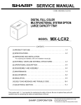
SERVICE MANUAL
CODE: 00ZMXCFX1/S1E
DIGITAL FULL COLOR
MULTIFUNCTIONAL SYSTEM
OPTION
INSERTER
MODEL
MX-CFX1
CONTENTS
[1] PRODUCT OUTLINE. . . . . . . . . . . . . . . . . . . . . . . . . . . . . . . . . . . . . . . . 1-1
[2] SPECIFICATIONS . . . . . . . . . . . . . . . . . . . . . . . . . . . . . . . . . . . . . . . . . . 2-1
[3] UNPACKING AND INSTALLATION
*For unpacking and installation, refer to the installation manual( [5] ).
[4] EXTERNAL VIEWS AND INTERNAL STRUCTURES . . . . . . . . . . . . . . 4-1
[5] OPERATIONAL DESCRIPTION . . . . . . . . . . . . . . . . . . . . . . . . . . . . . . . 5-1
[6] DISASSEMBLY AND ASSEMBLY . . . . . . . . . . . . . . . . . . . . . . . . . . . . . . 6-1
[7] MAINTENANCE. . . . . . . . . . . . . . . . . . . . . . . . . . . . . . . . . . . . . . . . . . . . 7-1
[8] ADJUSTMENTS . . . . . . . . . . . . . . . . . . . . . . . . . . . . . . . . . . . . . . . . . . . 8-1
[9] SIMULATION . . . . . . . . . . . . . . . . . . . . . . . . . . . . . . . . . . . . . . . . . . . . . . 9-1
[10] SELF DIAG MESSAGE AND TROUBLE CODE . . . . . . . . . . . . . . . . . 10-1
[11] ELECTRICAL SECTION . . . . . . . . . . . . . . . . . . . . . . . . . . . . . . . . . . . 11-1
Parts marked with " " are important for maintaining the safety of the set. Be sure to replace these parts with
specified ones for maintaining the safety and performance of the set.
SHARP CORPORATION
This document has been published to be used
for after sales service only.
The contents are subject to change without notice.
CONTENTS
[1] PRODUCT OUTLINE. . . . . . . . . . . . . . . . . . . . . . . . 1-1
[2] SPECIFICATIONS
1. Basic specifications . . . . . . . . . . . . . . . . . . . . . . 2-1
[3] UNPACKING AND INSTALLATION
*Forw unpacking and installation, refer to the installation
manual( [5] ).
[4] EXTERNAL VIEWS AND INTERNAL STRUCTURES
1. External components . . . . . . . . . . . . . . . . . . . . . 4-1
2. Sensors and switches . . . . . . . . . . . . . . . . . . . . . 4-1
3. Motors, solenoid, and clutch . . . . . . . . . . . . . . . . 4-2
[5] OPERATIONAL DESCRIPTION
1. Structure . . . . . . . . . . . . . . . . . . . . . . . . . . . . . . .
2. Function outline . . . . . . . . . . . . . . . . . . . . . . . . .
3. Operational description . . . . . . . . . . . . . . . . . . . .
4. Offline mode setting . . . . . . . . . . . . . . . . . . . . . .
5. LED indication on operator panel . . . . . . . . . . . .
6. Paper jam/error detection . . . . . . . . . . . . . . . . . .
5-1
5-1
5-1
5-4
5-6
5-7
[6] DISASSEMBLY AND ASSEMBLY
1. Paper feed separation unit . . . . . . . . . . . . . . . . .
2. Paper feed unit . . . . . . . . . . . . . . . . . . . . . . . . . .
3. Drive unit. . . . . . . . . . . . . . . . . . . . . . . . . . . . . . .
4. PWB . . . . . . . . . . . . . . . . . . . . . . . . . . . . . . . . . .
5. Motor. . . . . . . . . . . . . . . . . . . . . . . . . . . . . . . . . .
6. Other parts . . . . . . . . . . . . . . . . . . . . . . . . . . . . .
7. Note on assembly . . . . . . . . . . . . . . . . . . . . . . . .
6-1
6-2
6-4
6-4
6-4
6-5
6-7
[7] MAINTENANCE
1. Maintenance list . . . . . . . . . . . . . . . . . . . . . . . . . 7-1
[8] ADJUSTMENTS
1. Paper width detection level setting (adjustment) 8-1
[9] SIMULATION
1. List . . . . . . . . . . . . . . . . . . . . . . . . . . . . . . . . . . . 9-1
2. Details of trouble code . . . . . . . . . . . . . . . . . . . . 9-1
[10] SELF DIAG MESSAGE AND TROUBLE CODE 10-1
[11] ELECTRICAL SECTION
1. Actual wiring chart . . . . . . . . . . . . . . . . . . . . . . .11-1
2. Circuit description . . . . . . . . . . . . . . . . . . . . . . . .11-3
[1] PRODUCT OUTLINE
MX-CFX1
Service Manual
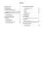
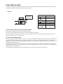
This inserter is an optional unit for the MX-5500N/MX-6200N/MX7000N series of digital complex machines. With the inserter
installed, blank sheets or printed sheets can be inserted as covers
(made of cardboard) or tabbed sheets without being subject to the
printing process (and without passing through a fixing unit). When
the inserter is combined with a finisher (optional) and a punch unit
(optional), printed sheets can proceed to the hole punching or stapling process without being subject to the copying process (or without passing through the main unit).
MX-CFX1
MX-CFX1 PRODUCT OUTLINE 1 – 1
[2] SPECIFICATIONS
MX-CFX1
Service Manual
1. Basic specifications
Name
Type
Transport reference
Productivity
Loading capacity
Paper size/weight
Mode
Offline function
Paper size/weight
Reliability
Life
Power supply
External dimensions (WxDxHmm)
Product dimensions (WxDmm)
Weight
Inserter
Floor standing
Center reference
Single-sided: 36 cpm, double-sided: 25 cpm
(when A4 size 8.5x11 paper is fed continuously)
100 sheets max. (standard paper: 80g/m2)
Refer to Table 1 ("Paper size/weight")
Stapling, saddle stitch, punching
As for the paper size/weight in each mode, rules for each mode shown in "Exit paper size/weight (finisher)" should be
observed.
MCBJ: Conforms to the main unit
MCBF: Conforms to the main unit
Conforms to the main unit
Supplied from the finisher
455x595x1050mm, 17 59/64x23 27/64x41 21/64 inch
565x595mm, 22 1/4x23 27/64 inch
Approx. 23kg, 50.7lbs
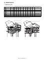
Table 1:Paper size/weight
Paper size
Thin paper
Normal paper
Type and
weight of
paper
that can
be fed
cardboard
1(including
gloss paper)
cardboard 2
Offset
Yes
Yes
Yes
Yes
Yes
Yes
Yes
Yes
Yes
Yes
Yes
Yes
Yes
Yes
Yes
Yes
Yes
Yes
Yes
Yes
Yes
Yes
No
Yes
Yes
Yes
Yes
Yes
No
No
No
Yes
Yes
Yes
Yes
Yes
No
No
Yes
Yes
No
No
No
No
Capacity
of paper
that can
be
stapled
No
30
30
50
30
50
No
No
No
30
30
30
50
30
No
No
30
50
No
No
No
No
Yes
Yes
Yes
Yes
Yes
Yes
Yes
Yes
Saddle
stitch
Punching,
2-holes
Punching,
3-holes
Punching,
4-holes
Punching,
4-holes,
wide
Inserter
paper
feed
No
Yes
Yes
No
Yes
No
No
No
No
Yes
Yes
No
No
Yes
No
No
Yes
No
No
No
No
No
No
Yes
Yes
Yes
Yes
Yes
Yes
No
No
Yes
Yes
Yes
Yes
Yes
Yes
No
Yes
Yes
Yes
No
No
No
No
Yes
No
Yes
No
No
No
No
No
Yes
Yes*3
Yes*3
Yes
Yes*3
No
No
No
No
No
No
No
No
No
Yes
No
Yes
No
No
No
No
No
Yes
No
No
Yes
No
No
No
No
No
No
No
No
No
No
Yes
Yes
Yes
Yes
Yes
Yes
No
No
Yes
Yes
Yes
Yes
Yes
Yes
No
No
No
No
No
No
No
Yes
Yes
Yes
Yes
Yes
Yes
Yes
Yes
Yes
Yes
Yes
Yes
Yes
Yes
Yes
Yes
Yes
Yes
Yes
No
No
No
Yes
Yes
Yes
Yes
Yes
Yes
Yes
Yes
Yes
Yes
Yes
Yes
Yes
Yes
Yes
Yes
Yes
Yes
Yes
*1
*2
*1
*2
Yes
Yes
Yes
Yes
Yes
No
No
No
Yes*5
No
No
No
Yes*5
No
No
No
Yes*5
No
Yes
No
Yes
Yes
No
No
No
No
OHP
Yes
No
No
No
No
Label paper
Yes
No
No
No
No
Tab paper
Yes
No
No*4
No
Yes*5
Stapling of 256g/m2 paper 2 sheets + 80g/m2 paper 48 sheets is enabled (cardboard is included).
Saddle stitch of 256g/m2 paper 1 sheet + 80g/m2 paper 14 sheets is enabled (cardboard is included).
Punching 3-holes is automatically changed to 2-holes.
While paper is fed from the inserter, stapling is enabled.
While paper is fed from the inserter, punch operation is enabled.
Envelope
*1)
*2)
*3)
*4)
*5)
A3W
A3
B4
A4
A4R
B5
B5R
A5R
12x18
11x17
8.5x14
8.5x13
8.5x11
8.5x11R
7.25x10.5R
5.5x8.5R
8K
16K
16KR
Postcard
Envelope
Special
55-59g/m2
15-16- lbs bond
60-105g/m2
16-28 lbs bond
106-209g/m2
28+-56lbsbond
210-256g/m2
56-68 lbs bond
75-90g/m2
20-24 lbs bond
Capacity
of paper
that can
be exited
MX-CFX1 SPECIFICATIONS 2 – 1
[4] EXTERNAL VIEWS AND
INTERNAL STRUCTURES
MX-CFX1
1. External components
2
3
4
Service
Manual
No.
Description
1
Paper feed tray
2
3
4
Paper guide
Top cover
Operator panel
5
Paper guiding
section (Lever)
Front cover
6
1
Function
Place blank or printed sheets to be inserted in this
tray.
Adjust this guide according to the paper size.
Open this cover to clear a paper jam.
Used to staple and punch during off-line. (The
same operation can be made with the operation
panel of the main unit.)
Unlock the paper guiding section to clear a paper
jam.
Open this cover to remove jammed paper from
the finisher or saddle finisher.
5
6
2. Sensors and switches
10
1
9
7
8
6
5
3
2
4
No.
1
Symbol
JCK_S W
Description
JAM cover open/
close switch
Type
Microswit
ch
Function and operation
Detects that the JAM cover is
opened or closed.
Output
When the JAM cover is
opened, TP37 turns HIGH.
MX-CFX1 EXTERNAL VIEWS AND INTERNAL STRUCTURES 4 – 1
Product name
(Model)
DE2L-FAAA
Manufacturer
HIROSE
CHERRY
PRECISION
2
H_SEN
Reverse sensor
Reflective
sensor
Detects that a sheet to be
inserted is transported to the
reverse sensor.
Detects that a sheet to be
inserted is transported to the
paper exit sensor.
Detects that the reverse unit is
opened or closed.
Detects that the inserter is
joined to the main unit.
3
HI_SEN
Paper exit sensor
Photointe
rrupter
4
HYK_SEN
5
S_SEN
Reverse unit open/
close sensor
Set sensor
Photointe
rrupter
Photointe
rrupter
6
EMP_SEN
Empty sensor
Photointe
rrupter
7
REG_SEN
Registration sensor
Photointe
rrupter
8
TIM_SEN
Timing sensor
Photointe
rrupter
9
T_VR
Potentiom
eter
10
T_SEN
Sheet width
detection
potentiometer
Tray sensor
Detects presence/absence of a
sheet to be inserted in the
paper feed tray.
Detects that a sheet to be
inserted is transported to the
registration sensor.
Detects that a sheet to be
inserted is transported to the
timing sensor.
Detects the width of a sheet to
be inserted in the tray.
Photointe
rrupter
Detects the length of a sheet to
be inserted in the tray
When a sheet is detected, TP1
turns HIGH.
SENSOR
(SNS - SPI-337-01)
SANYO
When a sheet is detected, TP7
turns LOW.
TLP1241 (C5)
TOSHIBA
When the reverse unit is
opened, TP9 turns LOW.
When the inserter is joined to
the main unit, TP16 turns
HIGH.
When a sheet is detected, TP4
turns HIGH.
TLP1241 (C5)
TOSHIBA
TLP1241 (C5)
TOSHIBA
TLP1241 (C5)
TOSHIBA
When a sheet is detected, TP5
turns LOW.
TLP1241 (C5)
TOSHIBA
When a sheet is detected, TP6
turns LOW.
TLP1241(C5)
TOSHIBA
The voltage of TP12 varies
between 0 V and 5 V
depending on the sheet width.
When a sheet is detected,
TP13 turns LOW.
RDC505003A
ALPS
GP1A73A
SHARP
3. Motors, solenoid, and clutch
3
5
1
2
6
7
4
No.
1
2
3
Symbol
K_MOT
H_MOT
Y_MOT
Description
Paper feed motor
Reverse motor
Horizontal transport motor
4
5
6
7
F_SOL
R_CL
PBA-PANEL
PBA-CONT
Flapper solenoid
Registration clutch
Operation panel PWB
Main control PWB
Function
Feeds a sheet to be inserted from the tray.
Reverses and ejects a sheet to be inserted.
Transports a sheet to be inserted on the horizontal transport
path.
Switches over the flapper in the reversing operation.
Holds the registration rollers to maintain registration.
-
Product name (Model)
23KM-K112-P5V
17PM-J507-P2VS
17PM-J507-P3VS
Manufacturer
MINEBEA
MINEBEA
MINEBEA
TDS-10SL-134
BJ-2.6-184
TDS
SHINKO
MX-CFX1 EXTERNAL VIEWS AND INTERNAL STRUCTURES 4 – 2
MX-CFX1
[5]
OPERATIONAL DESCRIPTION
3.
Operational
Service
Manual description
A. Through-mode operation of inserter (Online)
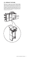
1. Structure
A. Cross-sectional view (Main body)
Pickup roller
Paper feed roller
Separation roller
Empty sensor
Registration roller
Registration sensor
Timing sensor
Vertical
transport roller
Paper exit sensor
Horizontal
transport roller 1
Reverse roller
Horizontal
transport roller 2
Reverse sensor
1)
The inserter receives an operation command sent by the main
unit.
2)
The transport motor rotates at a speed specified by the main
unit.
Horizontal transport rollers 1 (inlet rollers) and horizontal transport rollers 2 (paper exit rollers) rotate.
B. Drive system
[List of actuators]
Actuator
Description
Type
Paper feed
Pulse motor
motor
Transport motor
Pulse motor
Reverse motor
Reverse flapper
solenoid
Registration
clutch
Pulse motor
Solenoid
Electromagnetic
clutch
3)
A sheet exits from the main unit
4)
The paper exit sensor detects the leading edge of the sheet.
Components to be driven
Pickup roller, feed rollers, separation
rollers, registration rollers, vertical
transport rollers
Inlet rollers (horizontal transport rollers
1), paper exit rollers (horizontal
transport rollers 2)
Reverse rollers
Switch-over flapper in reverse section
Registration roller lock clutch
2. Function outline
A. Operation mode
1)
Normal (online mode)
• Through (horizontal transport)
• Straight mode (normal paper feeding from inserter)
• Reverse mode (reverse paper feeding from inserter)
2)
Offline mode
• Punching mode (inserter operation = normal paper feeding)
• Stapling mode (inserter operation = normal paper feeding)
B. Delivery speed
1)
Delivery speed
• Straight mode: 627 mm/sec
• Saddle mode (reverse): 276 mm/sec
5)
The paper exit sensor detects the trailing edge of the sheet.
6)
The transport motor stops.
Horizontal transport rollers 1 and horizontal transport rollers 2
stop.
MX-CFX1 OPERATIONAL DESCRIPTION 5 – 1
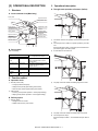
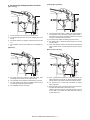
B. Normal paper feed operation of inserter
(online/offline)
[Paper loading]
9)
The paper feed motor starts to rotate in the forward direction.
The registration rollers and vertical transport rollers rotate.
10) The timing sensor detects the leading edge of the sheet.
1)
A sheet is placed in the paper feed tray of the inserter.
2)
The START LED lights up in blue on the operator panel of the
inserter.
3)
An operation command is sent by the main unit, or a user
presses the START switch on the operator panel of the
inserter.
4)
The registration clutch is turned ON to lock the registration rollers.
[Separation]
11) The leading edge of the sheet passes between the vertical
transport rollers.
12) When sheet transport needs to be suspended for adjusting the
space between sheets, the paper feed motor stops to stop the
sheet.
[Transport]
13) When a predetermined waiting time period has passed, The
paper feed motor restarts.
(If the transport motor has stopped, it is started.)
14) The paper exit sensor is turned ON, and detects the leading
edge of the sheet.
15) The timing sensor is turned OFF, and the trailing edge of the
sheet is detected.
16) When the trailing edge of the sheet leaves the vertical transport rollers, the paper feed motor stops.
(When there is a next sheet to be inserted, the paper feed
motor reverses to take it in.
[Paper exit]
5)
The paper feed motor reverses to lower the pickup roller,
thereby taking in the sheet from the paper feed tray.
6)
The registration sensor detects the leading edge of the sheet.
7)
The sheet makes contact with the registration rollers to form a
loop, thereby stopping the paper feed motor.
8)
The registration clutch is turned OFF.
17) The paper exit sensor is turned OFF, and the trailing edge of
the sheet is detected.
18) When there is no next sheet to be inserted, the transport motor
stops.
NOTE: While the transport motor (horizontal transport rollers 1 and
horizontal transport rollers 2) rotates at a speed specified
by the main unit in the online mode, it rotates at either of
the speeds shown below in the offline mode.
* Transport speed in offline mode
Small-sized sheet (of which length detected in the tray is 216 mm
or less): 627 mm/sec
Large-sized sheet (of which length detected in the tray is more
than 276 mm): 800 mm/sec
MX-CFX1 OPERATIONAL DESCRIPTION 5 – 2
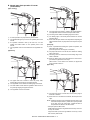
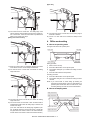
C. Reverse paper feeding operation of inserter
[Leading-edge registration]
[Paper loading]
9)
1)
A sheet is placed in the paper feed tray of the inserter.
2)
The START LED lights up in blue on the operator panel of the
inserter.
3)
The inserter reserves an operation command sent by the main
unit.
4)
The registration clutch is turned ON to lock the registration rollers.
[Separation]
The paper feed motor starts to rotate in the forward direction.
The registration rollers and vertical transport rollers rotate. If
the sheet is the first sheet, the flapper solenoid in the reverse
section is turned ON at this point of time.
10) The timing sensor detects the leading edge of the sheet.
11) The leading edge of the sheet passes between the vertical
transport rollers
12) When sheet transport needs to be suspended for adjusting the
space between sheets, the paper feed motor stops to stop the
sheet.
[Entering reverse section]
5)
The paper feed motor reverses to lower the pickup roller,
thereby taking in the sheet from the paper feed tray
6)
The registration sensor detects the leading edge of the sheet.
13) When a predetermined waiting time period has passed, the
flapper solenoid is turned ON, the paper feed motor restarts,
and the reverse motor starts to rotate in the forward direction.
7)
The sheet makes contact with the registration rollers to form a
loop, thereby stopping the paper feed motor.
14) The reverse sensor is turned ON, and detects the leading
edge of the sheet.
8)
The registration clutch is turned OFF.
15) When the trailing edge of the sheet leaves the timing sensor,
the paper feed motor starts to slow down to stop.
(After the paper feed motor has completely stopped, if there is
a next sheet to be inserted, the paper feed motor starts to
reverse to take it in.)
MX-CFX1 OPERATIONAL DESCRIPTION 5 – 3
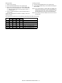
[Paper exit]
16) The reverse sensor is turned OFF. The trailing edge of the
sheet is detected, and the flapper solenoid in the reverse section is turned OFF. When the sheet travels a predetermined
distance, the reverse motor stops.
[Exiting from reverse section]
21) The paper exit sensor is turned OFF, and the trailing edge of
the sheet is detected.
22) If there is no next sheet to be inserted, the transport motor
stops.
4. Offline mode setting
A. How to set punching mode
The figure below shows the operator panel.
Start LED
Punch LED
Start switch
Punch switch
Setting procedure:
17) When the reverse motor has completely stopped, the reverse
motor starts to reverse, and the transport motor starts.
1)
Place a sheet in the tray.
2)
Press the PUNCH switch on the operator panel.
18) The reverse sensor is turned ON, and detects the leading
edge of the sheet.
3)
The PUNCH LED lights up to indicate that setting has been
completed.
4)
Press the START switch to start operation.
Canceling procedure:
5)
Press the PUNCH switch on the operator panel.
6)
The PUNCH LED goes out to indicate that setting has been
canceled.
NOTE: If you cannot make or cancel setting by following the
respective procedures above, refer to "5. LED indication on
operation panel" shown later. When no LEDs are lit, check
the setting made by the main unit and the inserter status.
B. How to set stapling mode
Staple mode LED 2
Staple mode LED 1
Start switch
19) The paper exit sensor is turned ON, and detects the leading
edge of the sheet.
20) The reverse sensor is turned OFF. When the sheet travels a
predetermined distance after its trailing edge is detected, the
reverse motor stops.
(If the next sheet waits at the leading-edge registration position, the flapper solenoid in the reverse section is turned ON,
the paper feed motor starts to rotate in the forward direction,
and the reverse motor starts to rotate in the forward direction.)
Staple mode LED 3
Start switch
Staple mode LED 4
Staple mode switch
MX-CFX1 OPERATIONAL DESCRIPTION 5 – 4
Setting procedure:
Canceling procedure:
1)
Place a sheet in the tray.
5)
Press the STAPLE MODE switch on the operator panel.
2)
Press the STAPLE MODE switch on the operator panel.
6)
3)
Each time you press the switch, the STAPLE MODE LEDs
light up by turns in the following order: 1, 2, 3, 4 All LEDs OFF
1 ... (When the saddle mode is cannot be used, the order is: 1
2, 3, All LEDs OFF 1 ...)
All the STAPLE MODE LEDs go out to indicate that setting has
been canceled.
4)
When the desired LED lights up, press the START switch to
start operation.
(Refer to the correspondence between the stapling modes and
LEDs shown later.)
NOTE: If you cannot make or cancel setting by following the
respective procedures above, refer to "5. LED indication on
operation panel" shown later. When no LEDs are lit, check
the setting made by the main unit and the inserter status.
NOTE: The punching mode and saddle mode cannot be used at
the same time.
The correspondence between the punching/stapling mode settings and LEDs is shown below.
Punch
LED
❍
❍
❍
❍
●
●
●
●
LED1
●
❍
❍
❍
❍
●
❍
❍
Staple mode LEDs
LED2
LED3
❍
❍
●
❍
❍
●
❍
❍
❍
❍
❍
❍
●
❍
❍
●
LED4
❍
❍
❍
●
❍
❍
❍
❍
Stapling mode
1-point stapling at back
2-point stapling
1-point stapling at front
Saddle stapling (saddle stitching)
Punching
Punching + 1-point stapling at back
Punching + 2-point stapling
Punching + 1-point stapling at front
* ●: means "Lit."
MX-CFX1 OPERATIONAL DESCRIPTION 5 – 5
5. LED indication on operator panel
Status
Cause
START LED
Red
Green
Explanation
Empty tray
The selected MODE LED is lit.
Inserter problem
Finisher problem
Paper jam in inserter
Paper jam in finisher
Inserter alarm
Finisher alarm
Open inserter cover
Open finisher cover
Offline operation disabled
Inserter tray specified stapling
mode non-usable
Punching non-usable
Operation mode Stapling disabled
Punching disabled
Full tray (considered as a kind of
finisher alarms)
Other
Paper-loaded tray
(Operable)
Paper-loaded
tray(Non-operable)
Paper-loaded tray
(Non-operable)
MODE LED
Lit
Lit
The LED of the selected mode is lit.
The LED of the selected mode is lit.
The LED of the selected mode is lit.
The LED of the selected mode is lit.
The LED of the selected mode is lit.
The LED of the selected mode is lit.
The LED of the selected mode is lit.
The LED of the selected mode is blinking.
The LED of the selected mode is lit.
Lit
Inserter problem
Finisher problem
Paper jam in inserter
Paper jam in finisher
Inserter alarm
Finisher alarm
Open inserter cover
Open finisher cover
Incompatible paper size
Lit
Lit
Lit
Lit
Blinking
Blinking
A non-usable paper size "A4
lateral," etc. is added when
the saddle mode is selected:
Extra size
Offline operation disabled
Inserter tray specified stapling
mode non-usable
Punching non-usable
Operation mode Stapling disabled
Punching disabled
Full tray (considered as a kind of
finisher alarms)
Over loaded
Paper loaded in the finisher
intermediate process tray
Other
Waiting for start of
offline operation
In offline operation
The LED of the selected mode is lit.
The LED of the selected mode is lit.
The LED of the selected mode is lit.
The LED of the selected mode is lit.
The LED of the selected mode is blinking.
The LED of the selected mode is lit.
The LED of the selected mode is lit.
The LED of the selected mode is lit.
Blinking
The selected mode is nonusable.
The LED of the selected mode is blinking.
The selected mode is
disabled.
The tray corresponding to the
selected mode is full.
The LED of the selected mode is blinking.
Blinking
The LED of the selected mode is blinking.
Blinking
Blinking
The LED of the selected mode is blinking.
The LED of the selected mode is lit.
Main unit status "operation
disabled," finisher status "nonoperable," etc.
After a user presses the
START switch
NOTE: For LED status, each blank means "not lit."
MX-CFX1 OPERATIONAL DESCRIPTION 5 – 6
The LED of the selected mode is lit.
Blinking
The LED of the selected mode is lit.
Blinking
The LED of the selected mode is lit.
6. Paper jam/error detection
A. List of Paper jams
Description
Not arrived at registration
sensor
Detection timing
At a time of separating a sheet
Not arrived at timing sensor
At a time of leading-edge registration
Not arrived at paper exit
sensor
At a time of paper exit in through mode
At a time of paper exit in normal paper
feed mode
At a time of paper exit in reverse paper
feed mode
Not arrived at reverse sensor
At a time of entering reverse section
At a time of exiting from reverse
section
Stay at registration sensor
Stay at paper exit sensor
At a time of paper exit in normal paper
feed mode
At a time of entering reverse section in
reverse paper feed mode
At a time of paper exit in normal paper
feed mode
At a time of entering reverse section in
reverse paper feed mode
At a time of paper exit in through mode
Stay at reverse sensor
At a time of paper exit in normal paper
feed mode
At a time of paper exit in reverse paper
feed mode
At a time of entering reverse section
Stay at timing sensor
At a time of exiting from reverse
section
Explanation
A paper jam is detected if the registration sensor is not turned ON, which means absence of a
sheet, even when the paper feed motor has been driven for a fixed distance after the pickup
roller starts to lower.
A paper jam is detected if the timing sensor is not turned ON, which means absence of a
sheet, even when the registration rollers (paper feed motor) have been driven for a fixed
distance after they are started.
A paper jam is detected if the paper exit sensor is not turned ON by the leading edge of a
sheet, which means absence of a sheet, even when the transport motor has been driven for a
fixed distance after the main unit sends a paper exit command.
A paper jam is detected if the paper exit sensor is not turned ON, which means absence of a
sheet, even when the leading edge of a sheet has traveled a fixed distance after it reaches the
paper exit rollers (horizontal transport rollers 2).
A paper jam is detected if the paper exit sensor is not turned ON, which means absence of a
sheet, even when a sheet has been transported a fixed distance by the transport motor after
the reverse sensor is turned ON, which means presence of a sheet.
A paper jam is detected if the reverse sensor is not turned ON, which means absence of a
sheet, even when the reverse motor has been driven for a fixed distance after leading-edge
registration.
A paper jam is detected if the reverse sensor is turned ON, which means absence of a sheet,
even when the reverse motor has been driven for a fixed distance while a sheet is exiting from
the reverse section.
A paper jam is detected if the registration sensor is not turned OFF, which means presence of
a sheet, even when the paper feed motor has been driven for a predetermined amount after a
sheet reaches the starting position of leading-edge registration.
A paper jam is detected if the timing sensor is not turned OFF, which means presence of a
sheet, even when the paper feed motor has been driven for a fixed distance after the
registration sensor is turned OFF, which means absence of a sheet.
A paper jam is detected if the paper exit sensor is not turned OFF, which means presence of a
sheet, even when the transport motor has been driven for a predetermined amount after the
paper exit sensor is turned ON, which means presence of a sheet.
A paper jam is detected if the paper exit sensor is not turned OFF, which means presence of a
sheet, even when the transport motor has been driven for a fixed distance after the trailing
edge of a sheet reaches the paper exit rollers (horizontal transport rollers 2).
A paper jam is detected if the reverse sensor is not turned OFF, which means presence of a
sheet, even when the reverse motor has been driven for a fixed distance after the timing
sensor is turned OFF, which means absence of a sheet.
A paper jam is detected if the reverse sensor is not turned OFF, which means presence of a
sheet, even when the reverse motor has been driven for a predetermined amount after the
reverse sensor is turned ON, which means presence of a sheet.
B. Error detection
C. Alarm detection
(1) EEPROM errors
Explanation:
Explanation:
An alarm is issued because the size of a sheet in the tray cannot be
correctly detected when both the sub tray pullout detection sensor
and the sub tray retraction detection sensor are turned OFF.
1)
Timeout error
The EEPROM is being programmed even after a predetermined time period (150 msec) has passed.
2)
Writing error
The written data does not match the read data even when writing and reading are retried.
3)
Indication:
Shown by a LED on the operator panel of the inserter or of the
main unit as an inserter alarm.
Reading error
Checking pieces of data read from three sources results in
mismatch even when checking is retried.
(2) Reverse sensor adjustment error
Explanation:
1)
When the DA output exceeds the upper limit
Even when the DA output is increased, the AD input value
does not fall within the appropriated range.
2)
When the DA output is less than the lower limit
Even when the DA output is decreased, the AD input value
does not fall within the appropriated range.
MX-CFX1 OPERATIONAL DESCRIPTION 5 – 7
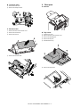
[6] DISASSEMBLY AND
ASSEMBLY
MX-CFX1
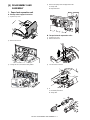
4)
Remove the
pickup roller and paper feed roller.
Service
Manual
A: Pickup roller
B: Paper feed roller
1. Paper feed separation unit
A. Pickup roller & paper feed roller
1)
Open the top cover.
A
B
B. Torque limiter & separation roller
2)
Remove the cover A.
1)
Open the top cover.
2)
Remove the cover A.
A
A
3)
Turning the unit A, remove the roller guide B.
3)
Turn the unit A to remove.
A
A
B
4)
Remove the torque limiter and the separation roller.
A: Horizontal pass roller 2
B: Timing roller
A
B
MX-CFX1 DISASSEMBLY AND ASSEMBLY 6 – 1
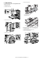
2. Paper feed unit
5)
Remove the top cover.
A. Horizontal pass roller 1 and registration roller
Paragraph in Sub Section.
1)
Open the top cover.
2)
Open the mount cover.
A: Horizontal pass roller 1
B: Registration roller
3)
Remove the front cover.
B
A
B. Horizontal pass roller 2 and timing roller
4)
1)
Open the top cover.
2)
Remove the front cover and rear cover.
3)
Remove the operating unit.
Remove the rear cover.
1
3
1
MX-CFX1 DISASSEMBLY AND ASSEMBLY 6 – 2
2
4)
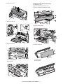
C. Reverse roller and reverse sensor
Remove the cover A.
1)
Open the top cover.
2)
Remove the front cover and rear cover.
3)
Remove the guide A to remove the stay B.
A
2
B
A
5)
1
Remove the tray unit.
2
2
4)
Remove the reverse unit.
2
1
1
2
3
3
6)
Remove the cover A.
5)
Remove the cover A.
A
A
A: Horizontal pass roller 2
B: Timing roller
A: Reverse sensor
B: Reverse roller
B
A
MX-CFX1 DISASSEMBLY AND ASSEMBLY 6 – 3
D. Paper guide
4. PWB
A. Operation panel PWB
1)
Remove the front cover.
2)
Remove the operating unit.
3)
Remove the operation panel PWB.
3. Drive unit
A. Belts
1)
Open the top cover.
2)
Remove the rear cover.
B. Main control PWB
1)
Remove the rear cover.
2)
Remove the main control PWB.
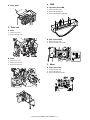
B. Gears
1)
Open the top cover.
2)
Remove the rear cover.
3)
Remove the drive unit.
5. Motor
A. Paper feed motor
1)
Remove the rear cover.
2)
Remove the drive unit.
3)
Remove the paper feed motor.
MX-CFX1 DISASSEMBLY AND ASSEMBLY 6 – 4
6. Other parts
B. Transport motor
1)
Remove the rear cover.
2)
Remove the transport motor.
A. Sensors
C. Reverse motor
1)
Remove the front cover and rear cover.
2)
Remove the reverse unit.
B. Tray sensor
3)
Remove the cover A.
1)
Open the top cover.
2)
Remove the front cover and rear cover.
3)
Remove the operating unit.
A
4)
Remove the tray unit.
5)
Disassemble the tray.
1
4)
Remove the reverse motor.
2
6)
Remove the tray sensor.
MX-CFX1 DISASSEMBLY AND ASSEMBLY 6 – 5
C. Registration sensor and empty sensor
F. Paper exit sensor
1)
Open the top cover.
1)
Remove the front cover and rear cover.
2)
Remove the front cover and rear cover.
2)
Remove the reverse unit.
3)
Detach the top cover.
3)
Remove the cover. (See the step 3 of 5-C.)
4)
Remove the registration sensor and the empty sensor.
4)
Remove the paper exit sensor.
A: Empty sensor
B: Registration sensor
B
A
G. Flapper solenoid
D. Set sensor
1)
Open the rear cover.
2)
Remove the set sensor
1)
Remove the rear cover.
2)
Remove the flapper solenoid.
E. Reverse unit open/close sensor
1)
Remove the front cover.
2)
Remove the reverse unit open/close sensor.
MX-CFX1 DISASSEMBLY AND ASSEMBLY 6 – 6
7. Note on assembly
A. Reverse flapper solenoid adjustment
1)
Rotate the solenoid lever (LVR-FM-SOL) fully clockwise.
2)
Adjust the position of the bracket (BKT-FM-SOL) of the solenoid so that the solenoid's arm is completely retracted (that
there is no clearance in the rubber spacer, the stopper E-ring,
and the main unit of the solenoid). When adjusted, fix the
bracket with screws.
LVR-FM-SOL
Stopper E-ring
Rubber spacer
Solenoid
main unit
Screw
BKT-FM-SOL
MX-CFX1 DISASSEMBLY AND ASSEMBLY 6 – 7
[7] MAINTENANCE
MX-CFX1
Service Manual
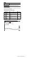
1. Maintenance list
✕: Checking (clean, replace or adjust as required) ❍: Cleaning ▲: Replace ∆: Adjust ✩: Lubricate ❏: Position shift
No.
Parts name
When
calling
300K
600K
900K
1200K
1500K
1800K
2100K
2400K
2700K
3000K
Remarks
Pickup rollers/
paper feed rollers
Torque limiter
Transport rollers
Transport paper
guides
✕
❍
❍
❍
❍
❍
❍
❍
❍
❍
❍
(Note 1)
✕
✕
✕
❍
✕
❍
✕
❍
✕
❍
✕
❍
✕
❍
✕
❍
✕
❍
✕
❍
✕
❍
(Note 2)
✕
❍
❍
❍
❍
❍
❍
❍
❍
❍
❍
5
Gears
✕
✩
✩
✩
✩
✩
✩
✩
✩
✩
✩
6
7
8
Belts
Sensors
Discharge brush
✕
✕
✕
✕
✕
✕
✕
✕
✕
✕
✕
✕
✕
✕
✕
✕
✕
✕
✕
✕
✕
✕
✕
✕
✕
✕
✕
✕
✕
✕
✕
✕
1
2
3
4
Lubricate necessary parts
(Specified positions)
Note 1 : Replacement reference: For replacement, refer to each paper feed port counter value: 150 K or 1 year after the start of use
Note 2 : Replacement reference: For replacement, refer to each paper feed port counter value: 400 K
2
7
6
5
1
6
7
4
3
3
7
4
7
MX-CFX1 MAINTENANCE 7 – 1
7
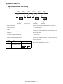
[8] ADJUSTMENTS
MX-CFX1
Service Manual
1. Paper width detection level setting
(adjustment)
LED 6
LED 5
PUNCH key
1)
LED 4
Operator panel
LED 3
LED 2
STAPLE key
LED 1
START key
Enter the diag mode.
4)
Press START key. (The selected diag mode is executed.)
Press and hold PUNCH key and START key, and turn on the
power of the main unit.
5)
Check that LED2 is flashing, and set the paper guide to the
max. width position.
The LCD display of the main unit turns on and off, then turns
on again.
6)
Press START key.
7)
Check that LED3 is flashing, and set the paper guide to A4R
width position.
Check that LED1 is flashing, and release PUNCH key and
START key.
8)
Press START key.
2)
Press START key.
9)
Check that LED4 is flashing, and set the paper guide to A5R
width position.
3)
Press PUNCH key and STAPLE key to set to the paper width
detection level setting (adjustment) mode.
The display changes to the diag mode.
The diag mode is displayed by combination of LED lighting.
: Lighting
Diag mode
No.
11
10) Press START key.
11) Check that LED5 is flashing, and set the paper guide to the
min. width position.
12) Press START key.
: OFF
Diag mode
When setting (adjustment) is completed normally, LED1 lights up.
When it is failed, LED1 flashes more rapidly.
LED lighting
Paper width detection level
setting (adjustment) mode
6
5
4
3
2
1
MX-CFX1 ADJUSTMENTS 8 – 1
[9] SIMULATION
MX-CFX1
Service Manual
1. List
Code
Main
Function (purpose)
Sub
30
3
Purpose
Used to check the operations of the sensors and detectors in the inserter and the
control circuits.
Used to check the operations of the loads in the inserter and the control circuit.
Used to set the adjustment value of the inserter paper width detection level.
31
32
2. Details of trouble code
Section
Operation test/Check
Inserter
Operation test/Check
Setting (Adjustment)
Inserter
Inserter
3-31
Operation test/Check
Purpose
3
Function (Purpose) Used to check the operations of the loads
in the inserter and the control circuit.
3-30
Inserter
Section
Operation test/Check
Purpose
Operation/Procedure
Function (Purpose) Used to check the operations of the sensors and detectors in the inserter and the
control circuits.
Inserter
Section
The operating conditions of the sensors and detectors are displayed.
Sensors and detectors which are turned on are highlighted.
TEST
Inserter sub tray pull-out detection
Inserter sub tray storage detection
Inserter tray paper length detection
Inserter tray empty detection
Inserter resist detection
Inserter timing detection
Inserter JAM cover open/close detection
Inserter reverse detection
Inserter paper exit detection
Inserter reverse unit open/close detection
Inserter start SW
Inserter staple mode select SW
Inserter punch select SW
Inserter set SW
TS_SEN
The selected load is operated.
K_MOT
Y_MOT
H_MOT
F_SOL
R_CL
P_LED
TEST
Inserter paper feed motor
Inserter horizontal transport motor
Inserter reverse motor
Inserter flapper solenoid
Inserter resist clutch
Inserter operation panel upper LED
T_SEN
EMP_SEN
REG_SEN
TIM_SEN
JCK_SEN
H_SEN
HI_SEN
HYK_SEN
P_ST_SW
P_MO_SW
P_PN_SW
SET_SW
CLOSE
SIMULATION NO.03-31
INSERTER LOAD CHECK
CLOSE
SIMULATION NO.03-30
FIN SENSOR CHECK
TH_SEN
2) Press [EXECUTE] key.
When [EXECUTE] is pressed, the operation is stopped.
Operation/Procedure
TH_SEN
TS_SEN
T_SEN
EMP_SEN
REG_SEN
TIM_SEN
JCK_SEN
H_SEN
HI_SEN
HYK_SEN
P_ST_SW
P_MO_SW
P_PN_SW
SET_SW
1) Select a target of the operation check with the touch panel.
1/1
MX-CFX1 SIMULATION 9 – 1
K_MOT
Y_MOT
H_MOT
F_SOL
R_CL
P_LED
EXECUTE
1/1
3-32
Setting (Adjustment)
Purpose
Function (Purpose) Used to set the adjustment value of the
inserter paper width detection level.
Inserter
Section
Operation/Procedure
1) Select an item corresponding to the adjustment content with [↑]
and [↓] keys on the touch panel.
2) Enter the adjustment value with 10-key.
3) Press [OK] key. (The set value is saved.)
Item
Display
MAX.
POSITION
A
B
POSITION 1
C
POSITION 2
D
MIN.
POSITION
TEST
Item
Inserter tray width detection
adjustment value (Max. width)
Inserter tray width detection
adjustment value (Adjustment
position 1)
Inserter tray width detection
adjustment value (Adjustment
position 2)
Inserter tray width detection
adjustment value (Min. width)
Set range
0 - 1023
0 - 1023
0 - 1023
0 - 1023
CLOSE
SIMULATION NO.03-32
INSERTER TRAY VALUE SETTING
A:
72
0
1023
A : 72
;
MAX. POSITION
B : 200
;
POSITION1
C : 10
;
POSITION2
D : 100
;
MIN. POSITION
OK
MX-CFX1 SIMULATION 9 – 2
MX-CFX1
[10]
SELF DIAG MESSAGE AND
TROUBLE CODE
Problem
Case1
Case2
Case3
Case4
Problem
Case1
Case2
Case3
Problem
Case1
Case2
Case3
The inserter does not perform at all when the main switch of
the main unit is turned ON.
Cause
Loose contact with the main unit
Check and
Check that each connector is firmly
remedy
connected.
Cause
Loose contact of the connector terminal of
the wire (interface harness) connecting with
the main unit
Check and
Check continuity in between the connector
remedy
terminals. Replace the connection wire if no
continuity is measured
Cause
JAM cover open/close switch fault
Check and
Check continuity between the switch
remedy
contacts. Replace the contacts if no
continuity is measured.
Cause
Controller PCB fault
Check and
Check that 24 V DC and 5 V DC are supplied
remedy
from the main unit after the above cases 1 to
3 are confirmed. If 24 V and 5 V are not
present at CN1-2 pin and IC5-32 pin on the
PCB, replace the controller PCB.
The paper feed motor does not operate.
The reverse motor does not operate.
The horizontal transport motor does not operate.
Cause
Loose contact of the motor connector
terminal
Check and
Check continuity of the connector
remedy
contacts.(CN1 to 3)
Cause
Disconnection of the motor coil
Check and
Check continuity between the connector
remedy
terminals. Replace the connection wire if no
continuity is measured.
Cause
Controller PCB fault
Check and
If the motor does not operate in the motor
remedy
single operation mode, replace the controller
PCB.
The paper is delivered without being reversed in the reverse
paper feed mode.
Cause
Connector terminal fault of the reverse
solenoid
Check and
Check continuity of the connector
remedy
contact.(CN4)
Cause
Disconnection of the solenoid coil
Check and
Inspect the coil for continuity. Replace the
remedy
coil if no continuity is measured.
Cause
Controller PCB fault
Check and
If the solenoid does not perform in the
remedy
solenoid single operation mode, replace the
controller PCB.
Service
Manual
Problem
Paper jam is displayed on the system display.
Case1
Case2
Cause
Check and
remedy
Cause
Check and
remedy
Case3
Cause
Check and
remedy
Case4
Cause
Check and
remedy
Case5
Cause
Check and
remedy
Case6
Cause
Check and
remedy
Case7
Cause
Check and
remedy
Problem
Case1
Case2
Paper jam
Visual observation. Take out paper jams.
Reverse sensor fault
Measure a voltage of TP2 on the controller
PCB and check that 3 to 3.6 V is observed
when no paper is stacked, and that 1.5 V or
less is observed when paper is stacked.
Replace the sensor if the measured voltage
exceeds these ranges.
Paper exit sensor fault
Measure a voltage of TP7 on the controller
PCB and check that 5 V is observed when no
paper is stacked, and that 1 V or less is
observed when paper is stacked. Replace
the sensor if the measured voltage exceeds
these ranges.
Empty sensor fault
Measure a voltage of TP4 on the controller
PCB and check that 1 V or less is observed
when no paper is stacked, and that 5 V is
observed when paper is stacked. Replace
the sensor if the measured voltage exceeds
these ranges.
Registration sensor fault
Measure a voltage of TP5 on the controller
PCB and check that 5 V is observed when no
paper is stacked, and that 1 V or less is
observed when paper is stacked. Replace
the sensor if the measured voltage exceeds
these ranges.
Timing sensor fault
Measure a voltage of TP6 on the controller
PCB and check that a 5 V is observed when
no paper is stacked, and that 1 V or less is
observed when paper is stacked. Replace
the sensor if the measured voltage exceeds
these ranges.
Controller PCB fault
If the problem is not solved with the sensors
whose level changes when each is turned
ON/OFF, replace the controller PCB.
The machine does not detect the paper.
Cause
Tray sensor fault
Check and
Measure a voltage of TP13 on the controller
remedy
PCB and check that 5 V is observed when no
paper is stacked, and that 1 V or less is
observed when paper is stacked. Replace
the sensor if the measured voltage exceeds
these ranges.
Cause
Controller PCB fault
Check and
If the problem is not solved with a change in
remedy
the sensor level after the above case 1 is
confirmed, replace the controller PCB.
MX-CFX1 SELF DIAG MESSAGE AND TROUBLE CODE 10 – 1
Problem
Case1
Case2
Case3
Problem
Case1
Case2
Problem
Case1
Case2
Case3
The machine does not detect the paper.
Cause
JAM cover open/close switch fault
Check and
Check continuity between the switch
remedy
contacts. Replace the switch if no conduction
is measured.
Cause
Reverse unit open/close sensor fault
Check and
Measure a voltage of TP9 on the controller
remedy
PCB and check that 1 V or less is observed
when the reverse unit is open, and that 5 V is
observed when the reverse unit is closed.
Replace the sensor if the measured voltage
exceeds these ranges.
Cause
Controller PCB fault
Check and
If the problem is not solved by a change in
remedy
the sensor level after the above cases 1 to 3
are confirmed, replace the controller PCB.
Inserter unset is displayed on the system display.
Cause
Set sensor fault
Check and
Measure a voltage of TP16 on the controller
remedy
PCB and check that 5 V is observed when
the inserter is set, and that 1 V or less is
observed when the inserter is not set.
Replace the sensor if the measured voltage
exceeds these ranges.
Cause
Controller PCB fault
Check and
If the problem is not solved by a change in
remedy
the sensor level after the above case 1 is
confirmed, replace the controller PCB.
The registration clutch does not perform.
Cause
Loose contact of the clutch connector
terminal
Check and
Check continuity of the connector contacts.
remedy
(CN4)
Cause
Disconnection of the clutch coils
Check and
Inspect the coils for continuity. Replace the
remedy
coils if no continuity is measured.
Cause
Controller PCB fault
Check and
If the clutch does not perform in the clutch
remedy
single operation mode, replace the controller
PCB.
MX-CFX1 SELF DIAG MESSAGE AND TROUBLE CODE 10 – 2
M E M O
MX-CFX1 SELF DIAG MESSAGE AND TROUBLE CODE 10 – 3
[11] ELECTRICAL SECTION
MX-CFX1
Service Manual
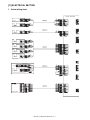
1. Actual wiring chart
PF3090 PBA-CONT
BE
BE
BE
SPI-337-01
Reverse sensor
PF3090K210
ASM-SNS-H
BE
BE
BE
BE
BE
BE
TLP1241(C5,F)
BE
BE
BE
Paper exit sensor
BE
BE
BE
TLP1241(C5,F)
PF3092K211
ASM-SNS-C-92
BE
BE
BE
Reverse unit open/close sensor
BE
BE
BE
TLP1241(C5,F)
Set sensor
BN
BN
BN
TLP1241(C5,F)
Empty sensor
PF3090K212
ASM-SNS-K
BK
BK
BK
TLP1241(C5,F)
BE
BE
BE
BN
BN
BN
BK
BK
BK
BE
BE
BE
Resistration sensor
BE
BE
BE
TLP1241(C5,F)
Timing sensor
Tray volume
Tray
BE
BE
BE
Housing
Contact
Tray sensor
PF3092K213
ASM-SNS-TR92
BE
BE
BE
BE
BE
BE
BE
BE
BE
BE
Housing
Contact
Housing
Contact
Operator panel
BE
BE
BE
BE
BE
BE
BE
BE
BE
BE
BE
PF3090K214
ASM-PANEL
BE
BE
BE
BE
BE
BE
BE
BE
BE
BE
BE
MX-CFX1 ELECTRICAL SECTION 11 – 1
090 PBA-CONT
RD
BK
YW
BE
WE
OE
RD
BK
YW
BE
WE
OE
Paper feed motor
Housing
Contact
OE
BE
YW
RD
BK
WE
OE
WE
BE
RD
BK
YW
Reverse motor
OE
WE
BE
RD
BK
YW
Horizontal
transport
motor
Housing
Contact
WE
BK
RD
YW
BE
OE
Housing
Contact
BE
BE
BE
BE
BE
BE
BE
BE
PF3090K219
ASM-SOL/CL
Flapper solenoid
BE
BE
BE
BE
Resistration clutch
BN
SB
PK
VT
YW
RD
BK
WE
GY
BK
OE
BE
RD
GY
Housing
Contact
Main Unit I/F
BN
SB
PK
VT
YW
BK
WE
Housing
Contact
RD
BN
YW
BK
PK
VT
PF3092K217
ASM-I/F-92
Housing
Contact
Contact
BK
BK
BE
BN
RD
BK
YW
PK
Finisher I/F
BE
VT
Housing
Contact
BK
OE
BE
Housing
Contact
Contact
RD
YW
BE
PF3090K218
ASM-SW
Housing
Contact
JAM cover open/close switch
YW
RD
BE
Sleeve
FASTON Terminal
MX-CFX1 ELECTRICAL SECTION 11 – 2
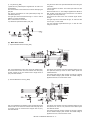
2. Circuit description
This circuit consists of the following divisions: managing signals
from the sensors, the switches, and the main unit; driving the
motors, the solenoid, and the clutch; the CPU and associated circuits.
A. Outline
This circuit controls paper feed, transport, reverse, and delivery.
Inserter
Main Unit
RXD0
ɛ
SGND
ɛ
TXD0
ɛ
Finisher
ɛ RXD1
COMMUNICATION
CIRCUIT
ɛ SGN
ɛ TXD1
H_SEN
HI_SEN
HYK_SEN
ROM
S_SEN
EMP_SEN
EEP ROM
SENSORS
INPUT
CIRCUIT
F_SOL
CPU
REG_SEN
R_CL
TIM_SEN
T_VR
T_SEN
DRIVER
P_ST_SW
P_MO_SW
SW
INPUT
CIRCUIT
P_PN_SW
P_PN_LED
P_MO_LED1
H_MOT
LED
DRIVE
CIRCUIT
Y_MOT
P_MO_LED2
P_MO_LED3
P_MO_LED4
P_ST_LED1
P_ST_LED2
DC+24V ɛ
DC+24Vġ ɛ
DC+5V
ɛ
K_MOT
JAM COVER
OPEN/CLOSED
DETECTION
CIRCUIT
(24V
CONDUCTIVE
DETECTION)
JCK_SW
INRUSH
CURRENT
LIMITING
CIRCUIT
ɛDC+24V
DC+5V
MX-CFX1 ELECTRICAL SECTION 11 – 3
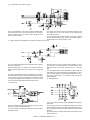
B. Circuit Detail
2)
RxD signal
(1) Communication Circuit
1)
Main Unit
TxD signal
Main Unit
F inis her
F inis her
This circuit communicates with the main unit and the finisher.
TxD0 and TxD1 are data signals transmitted from the main unit and the finisher to the inserter. RxD0 and RxD1 are data signals transmitted
from the inserter to the main unit and the finisher. Logical 1 is represented by +5V, and logical 0 is represented by 0V.
(2) Sensor Input Circuits
1)
Reverse Sensor (H_SEN)
R evers e S ens or
H_SEN uses the reflective sensor integrated with an LED and a
phototransistor.
The sensor detects a sheet between the sensor and the opposite
reflector interrupting the light path.
The CPU (IC6-Pin94, 95, 96) output is transmitted to the sensor to
light the LED through the D/A converter (IC13), the operational
amplifier (IC15.2), and the transistor (Q1). Meanwhile the signal is
transmitted to the CPU (IC6-Pin30) through the noise filters (R4,
C2) and the comparator (IC1.1).
The signal input to the CPU follows the logic: "H" when a sheet is
detected, "L" when not detected.
The analog signal is transmitted to CPU (IC-Pin105) through no
comparator.
R1 and R10 divide the +5V voltage which is applied to the comparator as the reference voltage.
R13 is used to make the reference voltage have hysteresis.
Paper Exit Sensor
Reverse Unit Open/Closed Sensor
Chassis Cover Open/Closed Sensor
Unused
2)
Paper Exit Sensor (HI_SEN)
HI_SEN uses the photointerrupter integrated with an LED and a
phototransistor.
The sensor detects a sheet with the lever actuator interrupting the
light path of the photointerrupter.
The signal is transmitted to the CPU (IC6-Pin106) through the
noise filters (R25,C9).
The signal input to the CPU follow the logic: "L" when a sheet is
detected, "H" when not detected.
MX-CFX1 ELECTRICAL SECTION 11 – 4
R39 is a current limiting resistor for the LED. R34 is a load resistor
for the sensor.
3)
Reverse Unit Open/Closed Sensor (HYK_SEN)
The signal is transmitted to the CPU (IC6-Pin108) through the
noise filters (R21,C7).
HYK_SEN uses the photointerrupter integrated with an LED and a
phototransistor.
The signal input to the CPU follows the logic: "L" when the reverse
unit is open, "H" when closed.
The sensor detects state of the reverse unit with the lever actuator
interrupting the light path of the photointerrupter.
R37 is a current limiting resistor for the LED. R32 is a load resistor
for the sensor.
S et S ens or
E mpty S ens or
R egis tration S ens or
T iming S ens or
4)
Set Sensor (S_SEN)
6)
Registration Sensor (REG_SEN)
S_SEN uses the photointerrupter integrated with an LED and a
phototransistor.
REG_SEN uses the photointerrupter integrated with an LED and a
phototransistor.
The sensor detects the main unit with the lever actuator interrupting
the light path.
The sensor detects a sheet with the lever actuator interrupting the
light path.
The signal is transmitted to the CPU (IC6-Pin2) through the noise
filters (R56,C16).
The signal is transmitted to the CPU (IC6-Pin32) through the noise
filters (R14,C5).
The signal input to the CPU follows the logic: "H" when the inserter
is connected to the main unit, "L" when not connected.
The signal input to the CPU follows the logic: "L" when a sheet is
detected, "H" when not detected.
R59 is a current limiting resistor for the LED. R58 is a load resistor
for the sensor.
R17 is a current limiting resistor for the LED. R16 is a load resistor
for the sensor.
5)
7)
Empty Sensor (EMP_SEN)
Timing Sensor (TIM_SEN)
EMP_SEN uses the photointerrupter including the LED and the
phototransistor in one unit.
TIM_SEN uses the photointerrupter integrated with an LED and a
phototransistor.
The sensor detects a sheet with the lever actuator interrupting the
light path.
The sensor detects a sheet with the lever actuator interrupting the
light path.
The signal is transmitted to the CPU (IC6-Pin31) through the noise
filters (R7,C4).
The signal is transmitted to the CPU (IC6-Pin33) through the noise
filters (R19,C6).
The signal input to the CPU is the following logic: the signal is "H"
when a sheet is detected, "L" when not detected.
The signal input to the CPU follows the logic: "L" when a sheet is
detected, "H" when not detected.
R12 is the current limiting resistor for the LED. R11 is the load
resistor for the sensor.
R18 is a current limiting resistor for the LED. R31 is a load resistor
for the sensor.
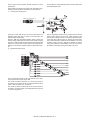
Paper Width Detection Potentiometer
Tray Sensor
Sub Tray Drawn Detection Sensor
Sub Tray Folded Detection Sensor
Unused
8)
Paper Width Detection Potentiometer (T_VR)
T_VR is a potentiometer.
The signal is transmitted to the CPU (IC6-Pin112) through the
noise filters (R48,C12).
The paper width is detected using the output voltage, which may
vary depending on the potentiometer's knob position.
MX-CFX1 ELECTRICAL SECTION 11 – 5
9)
Tray Sensor (T_SEN)
T_SEN uses the photointerrupter integrated with an LED and a
phototransistor.
The sensor detects a sheet with the lever actuator interrupting the
light path.
JCK_SW is the JAM cover open/closed detection switch using the
microswitch.
+24V is supplied to the switch. The contacts open when the JAM
cover is open.
The signal is transmitted to the CPU (IC6-Pin126) through the
noise filters (R46,C15).
When the switch turns on, +24V voltage is applied to the cathode of
ZD2, the base current flows to Q12, and Q12 turns on to transmit
the signal to the CPU (IC6-Pin111).
The signal input to the CPU follows the logic: "L" when a sheet is
detected, "H" when not detected.
The signal is also used as the +24V conduction signal simultaneously.
R52 is a load resistor for the sensor.
The signal input to the CPU follows the logic: "H" when the JAM
cover is open, "L" when closed.
10) JAM Cover Open/Closed Switch (JCK_SW)
The +24V conduction signal follows the logic: "L" when the +24V
voltage is conducted.
(3) Motor Drive Circuits
1)
Paper Feed Motor Drive Circuit (K_MOT)
P aper F eed MOT
Not Mounted
This circuit rotates/stops K_MOT and controls its rotational direction and the motor current. The circuit consists of the CPU (IC6),
the D/A converter (IC13), the constant-current chopper driver IC
(IC9), and other elements.
2)
The signals of the stepping-motor drive excitation pattern from the
CPU (IC6-Pin37,38,70,71) control the motor rotation speed and
rotational direction.
The analog signal from the D/A converter (IC13-Pin11) is divided
into the constant voltage by R53 and R54. The divided voltage is
applied to IC9-Pin9,11 to set the motor current.
Reverse Motor Drive Circuit (H_MOT)
R evers e MOT
Not Mounted
This circuit rotates/stops H_MOTand controls its rotational direction
and the motor current. The circuit consists of the CPU (IC6), the D/
A converter (IC13), the constant-current chopper driver IC (IC7),
and other elements.
The signals of the stepping-motor drive excitation pattern from the
CPU (IC6-Pin118, 120, 121, 122) control the motor rotation speed
and rotational direction.
The analog signal from the D/A converter (IC13-Pin5) is divided
into the constant voltage by R74 and R75. The divided voltage is
applied to IC7-Pin3,14 to set the motor current.
MX-CFX1 ELECTRICAL SECTION 11 – 6
3)
Transport Motor Drive Circuit (Y_MOT)
Horizontal
T rans port MOT
Not
Mounted
This circuit rotates/stops Y_MOT and controls its rotational direction and the motor current. The circuit consists of the CPU (IC6),
the D/A converter (IC13), the constant-current chopper driver IC
(IC8), and other elements.
4)
The signals of the stepping-motor drive excitation pattern from the
CPU (IC6-Pin97, 98, 101, 102) control the motor rotation speed
and rotational direction.
The analog signal from the D/A converter (IC13-Pin6) is divided
into the constant voltage by R76 and R77. The divided voltage is
applied to IC8-Pin3,14 to set the motor current.
Flapper Solenoid and Registration Clutch Drive Circuit (F_SOL and R_CL)
F lapper S OL
R egis tration C L
This circuit controls the flapper solenoid operation and the registration clutch engagement.
When the signal F_SOL is "H", Q2 turns on to activate the solenoid.
Similarly, when the signal R_CL is "H", Q3 turns on to engage the
clutch.
The flapper solenoid drive signal is the PWM signal. At the beginning of the solenoid activation, the signal is adjusted to set the solenoid at 100% duty cycle. After the plunger of the solenoid is pulled
in, the signal is adjusted to set the solenoid at 70% duty cycle in
order to reduce the temperature rise with the plunger hold.
5)
After the power is turned on, normally IC3-Pin8 (*RES) is "H". However, when the +5V voltage falls to 4.2V or less because of the
power turned off or any trouble, IC3-Pin8 turns "L" to reset the
CPU.
The clock signal from the CPU is transmitted to IC3-Pin3 (CK) at a
regular interval to clear the watchdog timer embedded in IC3. However, if the clock signal from the CPU disappears because of a system trouble, IC3-Pin8 turns "L" to reset the CPU and stop the
system operation.
6)
EEPROM Circuit
Reset Circuit
Not Mounted
This circuit consists of the data storage EEPROM and the peripheral circuits.
The circuit transmits a reset signal to the CPU when the power is
turned on or a power brownout is detected.
The circuit includes a watchdog timer intended to the CPU system
operation diagnosis.
IC4 is a storage memory for the adjustment settings of the reverse
sensor (reflective sensor) and the paper width detection potentiometer, and passes the data to the CPU through the four-wire serial
interface.
Once data is stored, the data is retained and not cleared even if the
power is turned off.
MX-CFX1 ELECTRICAL SECTION 11 – 7
IC4-Pin1 (CS) is the chip selection terminal, and stays "H" during
passing data.
IC4-Pin3 (DI) is the serial data input terminal. IC4-Pin4 (DO) is the
serial data output terminal.
IC4-Pin2 (SK) is the serial clock terminal. The serial data is transmitted synchronizing with the clock signal input to the terminal
7)
Inrush Current Limiting Circuit
J AM cover open/clos ed
system to a certain value or less. The circuit consists of the PTC
thermistor (PTH2) that limits a current and the FET (Q11) that
allows a steady current flowing.
When the JAM cover open/closed detection switch is closed, the
cathode voltage of ZD1 starts rising to the zener voltage according
to the time constant of R55 and C46. During the rise of the cathode
voltage, Q11 is off because no base current to Q10 keeps Q10 off,
and then a current flows to PTH2 to charge the regeneration capacitor.
8)
After the regeneration capacitor is fully charged, and the cathode
voltage of ZD1 reaches over the zener voltage according to the
time constant of R55 and C46, Q11 is turned on because the base
current from ZD1 to Q10 turns Q10 on. And then the current flows
to Q11 instead of PTH2 to release the current limitation. The circuit
consisting of PTH1 and D3 is intended to eliminate the electric
charge accumulated in C46 immediately to limit an inrush current
generated by momentary opening and shutting of the cover.
Operator Panel Drive Circuit
Operator P anel
This circuit includes the input circuits of the switches on the operator panel and the drive circuits of the LEDs.
The circuits connected to CN15-Pin1, 2, 3 are the input circuits of
the switches on the operator panel. The input signal from the switch
goes "L" when the switch is on, "H" when off.
The circuits connected to CN15-Pin4,6-11 are the drive circuits of
the LEDs on the operator panel. The LED lights when the signal is
"H", does not light when "L".
MX-CFX1 ELECTRICAL SECTION 11 – 8
9)
Operator Panel Circuit
This is the circuit of the operator panel board.
The operator panel drive board turns each of the LED1-6 on or off,
and detects weather each of the PSW1-3 is on or off.
MX-CFX1 ELECTRICAL SECTION 11 – 9
LEAD-FREE SOLDER
The PWB’s of this model employs lead-free solder. The “LF” marks indicated on the PWB’s and the Service Manual mean “Lead-Free” solder.
The alphabet following the LF mark shows the kind of lead-free solder.
Example:
<Solder composition code of lead-free solder>
Lead-Free
5mm
Solder composition
code (Refer to the
table at the right.)
a
Solder composition
Solder composition code
Sn-Ag-Cu
a
Sn-Ag-Bi
Sn-Ag-Bi-Cu
b
Sn-Zn-Bi
z
Sn-In-Ag-Bi
i
Sn-Cu-Ni
n
Sn-Ag-Sb
s
Bi-Sn-Ag-P
Bi-Sn-Ag
p
(1) NOTE FOR THE USE OF LEAD-FREE SOLDER THREAD
When repairing a lead-free solder PWB, use lead-free solder thread.
Never use conventional lead solder thread, which may cause a breakdown or an accident.
Since the melting point of lead-free solder thread is about 40°C higher than that of conventional lead solder thread, the use of the
exclusive-use soldering iron is recommendable.
(2) NOTE FOR SOLDERING WORK
©
Since the melting point of lead-freeCOPYRIGHT
solder is about 220°C, which
is about
40°C higher
than that of conventional lead solder, and its soldering
XXXX
BYSHARP
CORPORATION
capacity is inferior to conventional one, it is apt to keep the soldering iron in contact with the PWB for longer time. This may cause land
separation or may exceed the heat-resistive temperature
components.
Use enough care to separate the soldering iron from the PWB when
ALLofRIGHTS
RESERVED.
completion of soldering is confirmed.
Since lead-free solder includes a greater quantity of tin, the iron tip may corrode easily. Turn ON/OFF the soldering iron power frequently.
If different-kind solder remains on the soldering iron tip, it is melted together with lead-free solder. To avoid this, clean the soldering iron
tip after completion of soldering work. No part of this publication may be reproduced,
in a retrieval
orfile
transmitted
If the soldering iron tip is discolored black stored
during soldering
work,system,
clean and
the tip within
steel wool or a fine filer.
any form or by any means, electronic, mechanical,
photocopying, recording, or otherwise, without
prior written permission of the publisher.
* Applicable to battery-operated equipment
* Applicable to battery-operated equipment
SHARP CORPORATION
Digital Document System Group
CS Promotion Center
Yamatokoriyama, Nara 639-1186, Japan
2006 June Printed in Japan