1
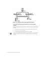
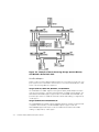
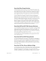
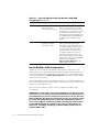
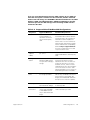
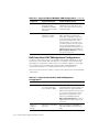
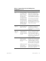
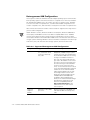
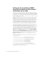
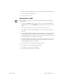
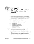
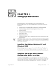
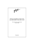
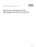
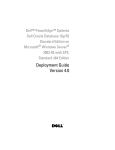
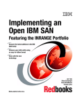
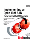
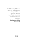
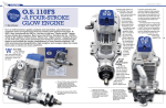
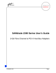
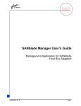
CHAPTER 2
SAN Configurations
This chapter introduces the components that you can include in your Storage Area
Network (SAN). It also explains the different operating system environments and
configurations that you can use in your SAN.
SAN Components
The following sections describe the various components in a SAN.
Servers
In a SAN, servers provide the attached client systems with access to high throughput,
reliable storage systems. Servers also manage the storage systems and attached
SAN appliances.
When you are installing, configuring, managing, or maintaining a server in a SAN, you
must consider both the installed operating system, software, and storage that is
being used on or by that server.
Server Software
The server software that is required on each server varies by the type of storage system it is using and by whether it is using a SAN Appliance.
Servers Accessing Storage Systems Directly
Ensure that each host server that is only accessing storage systems directly and not
through a PowerVault 530F SAN appliance, such as the server in Figure 2-1, has the
following software installed:
•
•
•
•
•
support.dell.com
Dell OpenManage Data Managed Node Data Agent (for 650F and 651F only)
Dell OpenManage Storage Consolidation (for 650F, 651F and 660F)
Dell OpenManage Application Transparent Failover (ATF) (for 650F and 651F
only)
QLogic QLdirect (for 660F only)
Dell OpenManage Array Manager (for 650F, 651F and 660F)
SAN Configurations
2-1
Figure 2-1. Example of Server Accessing Storage Systems
Servers Accessing Storage Systems Behind a PowerVault 530F SAN
Appliance
Ensure that each host server that is only accessing storage systems through a PowerVault 530F SAN appliance, such as the server in Figure 2-2, has the following software
installed:
•
•
•
Dell OpenManage Data Managed Node Data Agent (for 650F and 651F only)
QLogic QLdirect (for 530F and 660F)
Dell OpenManage Array Manager (for 650F, 651F and 660F)
NOTE: The PowerVault 530F SAN appliance comes with QLDirect, Dell OpenManage
Application Transparent Failover (ATF), and Dell OpenManage Array Manager preinstalled.
2-2
Dell PowerVault SAN Administrator’s Guide
Figure 2-2. Example of Server Accessing Storage Systems Behind a
PowerVault 530F
Servers Accessing Storage Systems Directly and Behind a 530F SAN
Appliance
Ensure that each host server that is accessing storage systems both directly and
through a PowerVault 530F SAN appliance, such as server in Figure 2-3, has the following software installed:
•
•
•
•
•
Dell OpenManage Data Managed Node Data Agent (for 650F and 651F only)
Dell OpenManage Storage Consolidation (for 650F, 651F, and 660F)
Dell OpenManage ATF (for 650F and 651F only)
QLogic Qldirect (for 660F only)
Dell OpenManage Array Manager (for 650F, 651F, and 660F)
NOTE: The PowerVault 530F SAN appliance comes with QLDirect, Dell OpenManage
Application Transparent Failover (ATF), and Dell OpenManage Array Manager preinstalled.
support.dell.com
SAN Configurations
2-3
Figure 2-3. Example of Server Accessing Storage Systems Directly
and Behind a PowerVault 530F
Host Bus Adapters
Within a SAN, a host bus adapter (HBA) provides the connectivity from the host computer system to the external Fibre Channel device or to a PowerVault 50F, 51F, or 56F
switch. The following HBAs are supported.
QLogic QLA2100, QLA2100F, QLA2200, and QLA2200F
The QLA2x00 series HBAs support a 33-megahertz (MHz), 64-bit Peripheral Component Interconnect (PCI) 2.1 interface (fully backward compatible with 32-bit PCI). The
QLA2100 and QLA2200 support copper media. The QLA2100F and QLA2200F support fiber-optic media. For additional information about HBA cabling, see Appendix A,
“Cable Types.”
QLogic QLA2200/66 and QLA2200F/66
The QLA2200/66 series HBAs support a 66-MHz, 64-bit PCI interface (fully backwardcompatible with 32-bit PCI). The QLA2200/66 supports copper media. The
QLA2200F/66 supports fiber-optic media. For additional information about HBA
cabling, see Appendix A, “Cable Types.”
2-4
Dell PowerVault SAN Administrator’s Guide
PowerVault Fibre Channel Switches
Dell PowerVault Fibre Channel switches are used for building and managing a SAN.
The PowerVault 50F and 51F are 8-port Fibre Channel switches, and the PowerVault
56F is a 16-port Fibre Channel switch. The switch is a key component of a SAN. The
switch’s primary function is to enable true switched Fibre Channel fabric configurations. The PowerVault Fibre Channel switches are necessary for PowerVault 650F,
651F, and 660F storage system configurations that include more than two servers.
In a fully redundant SAN configuration, at least two switches are required. Each
switch connects to one of the storage controllers in the PowerVault 650F, 651F, or
660F storage system, which allows all servers connected to the switch to access all
logical unit numbers (LUNs) bound on that storage controller. This why each server
must have two HBAs installed. Each HBA is connected to one switch and to one storage controller. Due to the failover capabilities provided by the Dell OpenManage
Application Transparent Failover (ATF) software for 650Fs and 651Fs and by QLogic
QLDirect for 660Fs, this configuration eliminates cables, switches, gigabit interface
converters (GBICs), and HBAs as single points of failure. If any one of these hardware
components fails, connectivity is maintained with no loss of data. The switch also
allows you to add and remove devices while the SAN is operational.
PowerVault 650F and 651F Disk Processor Enclosures
The PowerVault 650F storage system is a Fibre Channel-attached, external redundant
array of independent disks (RAID) subsystem. The configuration is expandable to 120
hard-disk drives with additional PowerVault 630F disk array enclosures (DAEs). Each
650F and 630F supports up to 10 hard-disk drives. This configuration supports one
650F and up to 11 630Fs connected through link controller cards (LCCs). Standard features include redundant power supplies, fans, and LCCs.
The PowerVault 651F is a stand-alone deskside enclosure. The enclosure contains a
PowerVault 650F DPE and a PowerVault 630F DAE, which together provide a maximum of 20 hard-disk drives.
PowerVault 660F and 224F Storage Systems
The PowerVault 660F storage system is a Fibre Channel-attached, external RAID storage system. The configuration is expandable to 112 hard-disk drives with additional
PowerVault 224F storage enclosures. Each 660F and 224F supports up to 14 hard-disk
drives. This configuration supports one 660F and up to seven 224Fs connected
through input-output (I/O) expansion modules. Standard features include redundant
power supplies, fans, I/O expansion cards, and loop resiliency circuit/SCSI enclosure
services (LS) modules.
PowerVault 35F Fibre Channel Multiport Bridge
The PowerVault 35F Fibre Channel multiport bridge is a small computer system interface (SCSI)-to-Fibre Channel protocol converter that enables SCSI-based high-voltage
differential (HVD) tape libraries and autoloaders, such as the PowerVault 130T
DLT4000 or DLT7000 library or 120T DLT4000 or DLT7000 autoloader, to be attached
to the Fibre Channel fabric and to be shared between multiple servers in the SAN.
support.dell.com
SAN Configurations
2-5
PowerVault 130T Library and 120T Autoloader
The PowerVault 130T library is a compact, tape-based, HVD SCSI-2 storage subsystem for data backup and restore for one or more servers and disk storage
subsystems. Referred to as a tape library, the PowerVault 130T features high capacity,
high throughput, data compression, automated backup capability, and reliable, accurate data restore functions.
The PowerVault 120T DLT4000 and DLT7000 autoloaders are fully automated, seventape, random-access tape autoloaders that are designed to be more effective network
backup solutions than manually operated stand-alone tape drives.
PowerVault 530F SAN Appliance
The Dell PowerVault 530F is a SAN appliance that offers a variety of functions,
depending on customer needs and application requirements. The primary function of
the PowerVault 530F is local and remote data mirroring for disaster recovery and data
replication. In addition, the system features Snapshot Copy, LUN masking, mapping
and partitioning, as well as the ability to boot a server through the PowerVault 530F
system.
For more information on PowerVault 530F features, refer to the documentation that
came with your system.
Supported SAN Configurations
A Dell SAN supports consolidation of storage for Microsoft Windows NT and
Windows 2000, both clustered and non-clustered, and consolidation of storage for
Novell NetWare. Each of these operating system environments are supported on
independent SANs or in separate zones on the same SAN. PowerVault 530F SAN
appliances can exist on the same SAN.
Windows NT and Windows 2000 SAN Configurations
Table 2-1 lists the maximum number of devices that the Windows NT or Windows
2000 SAN configurations can support.
2-6
Dell PowerVault SAN Administrator’s Guide
Table 2-1. Supported Windows NT and Windows 2000 SAN
Configurations
support.dell.com
Component
Supported Maximum
Conditions/Requirements
Servers
Maximum of 20 servers
running Windows NT
and Windows 2000; a
maximum of 24 servers for a backup-only
SAN.
See the Release Notes on the Dell
PowerVault Fibre Channel Utilities
CD Version 4.0 or the Dell PowerVault Fibre Channel Update CD
Version 4.0 or see the Dell PowerVault Storage Area Network (SAN)
Version 4.0 Revision Compatibility
Guide at http://support.dell.com
for a list of supported servers and
required revision levels.
Host bus
adapters
(HBAs)
Maximum of two HBAs
per server.
Allows a maximum of 40 HBAs in a
SAN and 48 HBAs in a backup-only
SAN.
Target storage
ports
Maximum of eight ports
for storage per fabric.
For the purpose of faulttolerance and loadbalancing, each 56F provides 10 ports for servers and four ports for
storage, and each 50F
and 51F provides five
ports for servers and
two ports for storage.
A maximum of eight ports are available for any combination of the following devices: PowerVault 35F
bridges, PowerVault 650F and 651F
disk processor enclosures (DPEs), or
PowerVault 660F storage systems.
35F bridges
Maximum of eight PowerVault 35F bridges
Allows a maximum of eight bridges
in a backup SAN.
120T
autoloaders
Maximum of four
PowerVault 120T
DLT4000 or DLT7000
autoloaders per PowerVault 35F bridge.
Allows a maximum of 32 PowerVault
120T autoloaders per SAN.
130T libraries
Maximum of two
PowerVault 130T
DLT4000 or DLT7000
libraries per PowerVault
35F bridge.
Allows a maximum of 16 PowerVault
130T libraries per SAN with a
maximum of four tape drives per
PowerVault 35F bridge.
For information on the 530F, see
Table 2-3.
SAN Configurations
2-7
Table 2-1. Supported Windows NT and Windows 2000 SAN
Configurations (continued)
Component
Supported Maximum
Conditions/Requirements
MSCS clusters
Maximum of 10
Microsoft Cluster
Server (MSCS) clusters.
Each MSCS pair with its PowerVault
storage system must be in its own
zone; see the latest clustering documentation for your systems, the Dell
PowerEdge Cluster F-Series SAN
Guide, and the Dell PowerEdge Cluster FE100/FL100 and FE200/FL200
Installation and Troubleshooting
Guide
Switches
Maximum of six PowerVault Fibre Channel
switches per SAN.
Three switches are supported per
fabric, allowing six switches for
redundant configurations and three
for nonredundant configurations. At
least one PowerVault 51F or 56F
switch per fabric is strongly recommended for support of a zoning
graphical user interface (GUI); see
the Dell PowerVault Systems Storage
Area Network Revision Compatibility
Guide, which is available at
http://support.dell.com, for the
latest release of the GUI.
Novell NetWare SAN Configurations
NetWare 4.2 and 5.1 with the appropriate support pack are supported (see the
Release Notes on the Dell PowerVault Fibre Channels Utilities CD Version 4.0 or the
Dell PowerVault Fibre Channel Update CD Version 4.0 for the correct support pack).
Access the Dell Web site at http://support.dell.com for the latest information about
supported operating systems.
The Dell OpenManage Storage Consolidation software does not support NetWare volumes. A Dell SAN requires the administrator to manually control the mounting of SAN
volumes on each NetWare server.
Table 2-2 lists the maximum number of devices supported in NetWare SAN
configurations.
NOTICES: For volumes to be accessed by a NetWare server, the server must
mount them. You can mount them by issuing the Mount command; however,
most administrators place the command in the autoexec.ncf file. After NetWare installation, the Mount all command is placed in the autoexec.ncf file
by default. The administrator must remove this command and replace it
with a series of Mount commands explicitly mounting each of the volumes
on the SAN that should be available to the server. For instructions, see
Chapter 12, “Installing, Configuring, and Uninstalling Components in a
Novell NetWare SAN.”
2-8
Dell PowerVault SAN Administrator’s Guide
If you are using Novell Storage Services (NSS) volumes in your SAN, you
must edit each system’s autoexec.ncf file. In this file, find the command
load nss.nlm and change it to LOAD NSS /AutoDeactivateVolume=all /MailboxSize=16000 /ClosedFileCacheSize=100000 /CacheBalance=60. This
command prevents the NSS manager from mounting all NSS volumes
attached to the SAN.
Table 2-2. Supported Novell NetWare SAN Configurations
support.dell.com
Component
Supported Maximum
Conditions/Requirements
Servers
Maximum of 20 servers
running NetWare; a
maximum of 24 servers for a backup-only
SAN.
See the Release Notes on the Dell
PowerVault Fibre Channel Utilities
CD Version 4.0 or the Dell PowerVault Fibre Channel Update CD
Version 4.0 or see the Dell PowerVault Storage Area Network (SAN)
Version 4.0 Revision Compatibility
Guide at http://support.dell.com
for a list of supported servers and
required revision levels.
Host bus
adapters
(HBAs)
Maximum of two HBAs
per server.
Allows a maximum of 40 HBAs in a
SAN and 48 HBAs in a backup-only
SAN.
Management
station
One Windows NT or
Windows 2000 system
is required for managing
storage.
The Windows NT or Windows 2000
management station must be
attached to the same local-area or
wide-area network as one of the
NetWare servers, which must be
SAN-attached to the other NetWare
servers. At least one of the SANattached NetWare servers must run
Data Managed Node for NetWare.
Target storage
ports
Maximum of eight ports
for storage per fabric.
A maximum of eight ports are available for any combination of the following devices: PowerVault 35F
bridge, PowerVault 650F and 651F
disk processor enclosures (DPEs).
35F bridges
Maximum of eight
PowerVault 35F bridges
Allows a maximum of eight bridges
in a backup SAN.
120T
autoloaders
Maximum of four PowerVault 120T DLT4000
or DLT7000 autoloaders per PowerVault 35F
bridge.
Allows a maximum of 32 PowerVault
120T autoloaders per SAN.
SAN Configurations
2-9
Table 2-2. Supported Novell NetWare SAN Configurations (continued)
Component
Supported Maximum
Conditions/Requirements
130T libraries
Maximum of two
PowerVault 130T
DLT4000 or DLT7000
libraries per PowerVault
35F bridge.
Allows a maximum of 16 PowerVault
130T libraries per SAN with a maximum of four tape drives per PowerVault 35F bridge.
Switches
Maximum of six PowerVault Fibre Channel
switches per SAN.
Three switches are supported per
fabric, allowing six switches for
redundant configurations and three
for nonredundant configurations. At
least one PowerVault 51F or 56F
switch per fabric is strongly recommended for support of a zoning GUI;
see the Dell PowerVault Systems
Storage Area Network Revision Compatibility Guide, which is available at
http://support.dell.com, for the latest release of the GUI.
Dell PowerVault 530F SAN Appliance Configurations
A SAN zone that contains one or more Dell PowerVault 530F SAN appliances is considered to be a PowerVault 530F SAN appliance configuration. A PowerVault 530F
SAN appliance configuration contains either one stand-alone appliance or two appliances configured as a redundant pair. Each PowerVault 530F SAN appliance
configuration (stand-alone or redundant pair) must be in a separate zone.
Table 2-3 lists the maximum number of components supported in a PowerVault 530F
configuration.
Table 2-3. Supported PowerVault 530F SAN Appliance
Configurations
2-10
Component
Supported Maximum
Conditions/Requirements
Servers
Maximum of 20 servers running Windows
NT or Windows 2000.
See the Release Notes on the Dell
PowerVault Fibre Channel Utilities CD
Version 4.0 or the Dell PowerVault
Fibre Channel Update CD Version 4.0
or see the Dell PowerVault Storage
Area Network (SAN) Version 4.0
Revision Compatibility Guide at
http://support.dell.com for a list of
supported servers and required revision levels.
Host bus
adapters
(HBAs)
Maximum of two HBAs
per server.
Allows a maximum of 40 HBAs in a
SAN and 48 HBAs in a backup-only
SAN.
Dell PowerVault SAN Administrator’s Guide
Table 2-3. Supported PowerVault 530F SAN Appliance
Configurations (continued)
support.dell.com
Component
Supported Maximum
Conditions/Requirements
Target storage
ports
Maximum of eight ports
for storage per fabric.
For the purpose of faulttolerance and loadbalancing, each PowerVault 56F switch provides 10 ports for
servers and four ports
for storage, and each
PowerVault 51F switch
provides five ports for
servers and two ports
for storage. (The PowerVault 50F switch is not
supported in a PowerVault 530F SAN appliance configuration.)
A maximum of eight ports are available for any combination of the
following devices: PowerVault 35F
bridges, PowerVault 650F and 651F
disk processor enclosures (DPEs),
PowerVault 660F storage systems,
and PowerVault 530F SAN appliances.
530F SAN
appliances
Maximum of four
PowerVault 530F SAN
appliances per SAN.
Maximum of four PowerVault 530Fs
in a stand-alone configuration per
SAN. Maximum of two pairs of
PowerVault 530Fs in a redundant pair
configuration.
650F or 651F
DPEs and
660F storage
systems
Maximum of four
PowerVault 650F, 651F,
or 660F systems connected to each PowerVault 530F configuration
in a SAN.
Maximum of four PowerVault storage
systems connected to one standalone or one redundant pair of PowerVault 530Fs using Fibre Channel
switches. Both 650Fs and 660Fs can
be attached in the same 530F configuration; however, you cannot mix the
two types of storage systems in a
clustered configuration.
Switches
Maximum of six PowerVault Fibre Channel
switches per SAN
between the server and
the 530F.
Between the server and the PowerVault 530F: Three switches per fabric
allowing six switches for redundant
configurations and three for nonredundant configurations. PowerVault
56Fs are recommended for scalability.
PowerVault 50Fs are not supported.
If 660F storage systems
are used, one or more
switches may be
required between the
530F and the 660F.
Between the PowerVault 530F and
660F: One switch per fabric is
required when using PowerVault 660F
storage systems. PowerVault 51F and
56F switches are supported.
Each stand-alone PowerVault 530F
uses two storage ports per fabric
between the server and the PowerVault 530F. Each redundant pair of
PowerVault 530Fs uses three storage
ports per fabric between the server
and the PowerVault 530F.
SAN Configurations
2-11
Heterogeneous SAN Configurations
Heterogeneous SANs are SANs that include multiple operating system environments.
Each operating system environment must be in a separate zone. However, Windows
NT and Windows 2000 servers can reside in the same or separate zones. NetWare
servers must reside in a separate zone, each PowerVault 530F configuration must
reside in a separate zone, and each MSCS cluster pair must reside in a separate zone.
Table 2-4 lists the maximum number of devices that are supported in a single heterogeneous SAN configuration.
NOTE: Windows servers, Windows NT MSCS cluster pairs, Windows 2000 MSCS
cluster pairs, and NetWare servers must all be in separate fabric zones. NetWare
servers cannot share the same storage systems with Windows servers or MSCS
cluster pairs. Windows NT and Windows 2000 servers can share the same zone and
storage systems. Although Windows servers and MSCS cluster pairs must be in separate zones, they can share the same storage system, but not the same LUN.
Table 2-4. Supported Heterogeneous SAN Configurations
2-12
Components
Supported Maximums
Conditions/Requirements
Servers
Maximum of 20 servers; a maximum of 24
servers for a backuponly SAN.
Each MSCS pair with its PowerVault
650F, 651F, or 660F storage system
must be in its own zone. All Windows
NT or Windows 2000 servers running
Storage Consolidation must be in
their own zone along with their storage nodes. All NetWare servers must
be in their own zone along with their
associated storage nodes (NetWare
4.2 and 5.1 may exist in the same
zone). See the Release Notes located
on the Dell PowerVault Fibre Channel
Utilities CD or the Dell PowerVault
Fibre Channel Update CD, the Dell
PowerEdge Cluster F-Series SAN
Guide, the Dell PowerEdge Cluster
FE100/FL100 and FE200/FL200
Installation and Troubleshooting
Guide, or the Dell PowerVault Storage
Area Network (SAN) Version 4.0
Revision Compatibility Guide at
http://support.dell.com for the
latest list of servers and revision
levels required.
Host bus
adapters
(HBAs)
Maximum of two HBAs
per server.
Allows a maximum of 40 HBAs in a
SAN and 48 HBAs in a backup-only
SAN.
Dell PowerVault SAN Administrator’s Guide
Table 2-4. Supported Heterogeneous SAN Configurations (continued)
support.dell.com
Components
Supported Maximums
Conditions/Requirements
Management
station
One Windows NT or
Windows 2000 system
is required for managing
storage.
The Windows NT or Windows 2000
management station must be
attached to the same local- or widearea network as the NetWare
servers. One of the SAN-attached
NetWare servers must be running
Data Managed Node for NetWare.
650F, 651F,
and 660F
Each PowerVault 650F,
651F, and 660F requires
one of the following:
PowerVault 660F storage systems
are supported only in Windows and
PowerVault 530F zones.
Target storage
ports
Maximum of eight ports
for storage per fabric.
A maximum of eight ports are available for any combination of the
following devices: PowerVault 35F
bridge, PowerVault 650F and 651F
disk processor enclosures (DPEs),
PowerVault 660F storage systems,
and PowerVault 530F SAN appliances. (Each stand-alone PowerVault
530F uses two storage ports on the
switch between the server and the
PowerVault 530F. Each redundant pair
of PowerVault 530Fs uses three storage ports on the switch.)
35F bridges
Maximum of eight
PowerVault 35F bridges
Allows a maximum of eight bridges in
a backup SAN.
120T
autoloaders
Maximum of four
PowerVault 120T
DLT4000 or DLT7000
autoloaders per PowerVault 35F bridge.
A maximum of 32 PowerVault 120T
autoloaders per SAN.
130T libraries
Maximum of two
PowerVault 130T
DLT4000 or DLT7000
libraries per PowerVault
35F bridge.
A maximum of 16 PowerVault 130T
libraries per SAN with a maximum of
four tape drives per PowerVault 35F
bridge.
Switches
Maximum of six PowerVault Fibre Channel
switches per SAN.
Three switches are supported per
fabric, allowing six switches for
redundant configurations and three
for nonredundant configurations. At
least one PowerVault 51F or 56F
switch per fabric is strongly recommended for support of a zoning GUI;
see the Dell PowerVault Systems
Storage Area Network Revision Compatibility Guide, which is available at
http://support.dell.com, for the
latest release of the GUI.
SAN Configurations
2-13
Getting the Connected Device WWNs
Using the PowerVault 5xF Fibre Channel
Switch Name Server Table
Zoning is required in heterogeneous SAN configurations to separate incompatible
environments, such as separating Windows environments and storage from NetWare
environments. It may be used in other configurations depending on the components
and environments in your SAN. Zoning uses World-Wide Names (WWNs) to uniquely
identify each target device in a SAN.
You can obtain the WWNs of devices that are connected to each switch by using the
nsShow command through a Telnet or serial session. This command lists the contents of the name server table in the switch. The list of WWNs are sorted by the
physical port number to which the devices are connected. (The position in the name
server table listing does not identify the physical port to which the device is connected.) The WWN listing shows both the port and node WWNs. This method of
obtaining the WWNs is recommended if the fabric contains only PowerVault 50F
switches; however, it can be used for PowerVault 51F and 56F switches as well.
In a fabric with a PowerVault 51F or 56F switch (running version 2.1.x firmware), the
name server information for the entire fabric can be accessed from the Dell
PowerVault Switch Manager application program using a Web browser. To access the
name server information, start the Switch Manager application program by connecting to a PowerVault 51F or 56F switch through a Web browser (see the Dell
PowerVault Switch Manager User’s Guide for more information). From the Fabric
View page (the first page displayed in the browser), click the Name Server Table
button to launch the Name Server Table View. The table displays the port and node
WWNs of each device in the fabric, the switch to which the device is connected
(identified by domain ID), and the physical port to which the device is connected. The
Name Server Table View also identifies zone membership information for the
device.
The following WWN information can be used to identify each type of device that is
connected to a switch:
•
•
•
•
•
•
xx:xx:00:60:69:xx:xx:xx — PowerVault 50F, 51F, or 56F switch
xx:xx:00:60:16:xx:xx:xx — PowerVault 650F storage processor
xx:xx:00:80:e5:xx:xx:xx — PowerVault 660F storage system
xx:xx:00:e0:8b:xx:xx:xx — QLA2100/2200 HBA
xx:xx:00:e0:02:xx:xx:xx — PowerVault 35F bridge
xx:xx:00:b0:d0:xx:xx:xx — PowerVault 530F SAN appliance
For more information on using WWNs when configuring zones, see Chapter 15,
“Managing Fibre Channel Fabric Switch Zones.”
2-14
Dell PowerVault SAN Administrator’s Guide
Attaching Cables
For an illustration of how some of the components are cabled in a SAN, see the
cabling example in Figure 2-4. For more information about cables that can be used in a
SAN, see Appendix A, “Cable Types.”
Figure 2-4. SAN Cabling Configuration Example
Cabling Servers to PowerVault Storage
Systems
Perform the following steps to cable your servers to a 650F, 651F, or 660F PowerVault
storage system. For additional cabling information, see Appendix A, “Cable Types.”
1.
support.dell.com
Turn off the server(s) and the PowerVault 650F, 651F, or 660F storage systems.
SAN Configurations
2-15
NOTICE: Do not turn on the server(s) or the PowerVault storage systems
until all cabling is complete.
2.
3.
Create an interface between the 50F, 51F, or 56F Fibre Channel switches and
each of the servers that you want to install in the SAN (see Figure 2-4).
a.
Connect the high-speed serial data connector (HSSDC) on the interface
cable to the QLogic HBAs on each server.
b.
Connect the other end of the cable to the 5xF Fibre Channel switch.
Create an interface between each of the storage processors (SPs) or RAID controllers on the storage systems and the Fibre Channel switch.
a.
Connect the HSSDC connector on each cable to the switch.
b.
Connect the DB-9 connector on the other end of the cable to one of the 9pin connectors on the SP modules or RAID controllers (I/O modules).
4.
For each NetWare server, verify the connection between the server and a
Windows NT or Windows 2000 management station on the local area network
(LAN). Otherwise, proceed to step 5.
5.
Power on all Fibre Channel switches, and then power on the PowerVault storage
systems.
This step takes 3–5 minutes and ensures that the PowerVault storage systems
are completely booted.
6.
Power on the server(s).
7.
Complete any switch zoning before continuing. For information about zoning, see
Chapter 15, “Managing Fibre Channel Fabric Switch Zones.”
Powering Up and Shutting Down a SAN
To power up or shut down the complete, fully configured SAN, follow the procedures
provided in this section.
NOTE: If this is the first time you are bringing up your SAN, follow the applicable procedures in Chapters 5 through 8. Use the following procedure for an existing (fully
installed and configured) SAN.
Powering Up a SAN
NOTE: All devices identified in a step must be fully booted before continuing to the
next step.
2-16
1.
Verify that all cables are properly attached.
2.
Power up all Fibre Channel switches and bridges.
3.
Turn on all 224F and 630F storage enclosures.
Dell PowerVault SAN Administrator’s Guide
4.
Power up all 660F and 650F storage systems and tape libraries and autoloaders.
5.
Power up all 530F SAN appliances.
6.
Power up all host servers.
Shutting Down a SAN
NOTE: All devices identified in a step must be fully shut down before continuing to
the next step.
support.dell.com
1.
For PowerVault 660F and 224F storage systems, open the Dell OpenManage
Array Manager and use the shutdown command to prepare the cache for shut
down.
2.
Shut down all host servers, and ensure that the power is turned off.
3.
Shut down all PowerVault 530F SAN appliances, and ensure that the power is
turned off.
4.
For PowerVault 650F, 651F, and 630F storage system arrays, turn off the power on
the storage processors and wait for complete shutdown of the 650F or 651F.
When the 650F or 651F shuts down, you can shut down the rest of the array by
turning off the power in the 630F storage systems.
5.
For PowerVault 660F storage systems, wait until the Cache Dirty LED is off, then
turn off the power. For information about the Cache Dirty LED, see your Dell
PowerVault 660F and 224F documentation.
6.
Turn off power to the PowerVault 224F storage systems.
7.
Turn off power to all tape libraries and autoloaders.
8.
Turn off power to all Fibre Channel bridges.
9.
Turn off power to all Fibre Channel switches.
SAN Configurations
2-17
2-18
Dell PowerVault SAN Administrator’s Guide