1
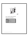
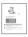
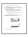
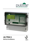
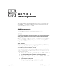
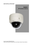
®
Dell PowerVault™ 130T Library
DRIVE INSTALLATION GUIDE
www.dell.com
®
Dell PowerVault™ 130T Library
DRIVE INSTALLATION GUIDE
www.dell.com
____________________
Information in this document is subject to change without notice.
© 1997–1998 Dell Computer Corporation. All rights reserved.
Reproduction in any manner whatsoever without the written permission of Dell Computer Corporation
is strictly forbidden.
Trademarks used in this text: Dell, the DELL logo are registered trademarks, and PowerVault is a trademark of Dell Computer Corporation.
Other trademarks and trade names may be used in this document to refer to either the entities claiming
the marks and names or their products. Dell Computer Corporation disclaims any proprietary interest
in trademarks and trade names other than its own.
October 1998
5085D
Vendor P/N 61839
PowerVault 130T Drive
Installation Instructions
DLT Drive Tray Assembly
These installation instructions describes how to remove, install and configure a DLT Drive
Tray Assembly into the PowerVault 130T.
Before beginning this procedure be sure to take note of your drive configuration. You may
need this later to reconfigure your new or additional drives.
NOTE: Tape drives are hot swappable, meaning they can be removed and replaced without
powering off the library or interrupting its operations. Hot swapping should only be
performed by trained technicians.
WARNING: HIGH VOLTAGE! DO NOT TOUCH any components on the power
supply located within the electronics module or on the drive trays. Live voltage
could be present even though the unit is powered off. (Refer to U03 in Safety
Booklet)
Removing the DLT Drive Tray Assembly
CAUTION: If the drives are daisy-chained do not disconnect them from the bus
without stopping all data processing on the channel. Before disconnecting the
external SCSI cables, make sure there is no activity on the SCSI bus. The host
must be quiesced, meaning that there is no activity on the SCSI bus. Do not
disconnect a hot bus. Any third party software must be quiesced. All signals
must be terminated at each end of the SCSI bus.
Follow the instructions below to remove a DLT Drive Tray Assembly. The tape drives are
located in the tape drive slots at the left rear of the library.
1.
Loosen the three thumbscrews from the hinged door at the rear of the library and
open the door.
Drive Tray Conversion Instructions
1
Figure 1. Back Vziew of Drive Tray Assembly
Back View of Drive Tray Assembly
2
Item
Number
Parts Description
1
Tape Drive
2
Thumbscrew (3x)
3
Hinged Door
Drive Tray Assembly Conversion Instructions
Figure 2. Interface Connection and Power
Interface Connection and Power
Item
Number
Parts Description
1
Power Receptacle
2
Tape Drive Interface Connector
3
Thumbscrew (2x)
2.
Disconnect the power cable from the tape drive.
CAUTION: Disconnect the tape drive interface cable (P980-P983), as described
in the next step, before removing the tape drive. Make sure the cable is out of
the tape drive bay by removing it from the rectangular hole to prevent the
cable from being damaged.
3.
Disconnect the tape drive interface cable from the tape drive.
NOTE: The tape drive interface cable (P980-P983) markings face the rear of the tape drive.
Note this orientation when reinstalling the drive interface cable. The connector is keyed but
it is still possible to insert it incorrectly.
4.
Disconnect the SCSI cable connectors and/or terminator from the rear of the drive.
Save the old terminator, if any.
Drive Tray Conversion Instructions
3
5.
Loosen the two thumbscrews at the rear of the drive assembly.
6.
Using both hands, remove the drive assembly from the drive slot, placing it on a flat,
stable surface.
WARNING: DO NOT apply power to the tape drive when it is outside of the
drive slot. To avoid damaging the drive, do not operate the load latch manually
while the drive is outside the library.
Replacing the Tape Drive Tray assembly
1.
If you are replacing your drive with a new drive, unpack the assembly and inspect it for
damage such as bent, broken, or loose parts.
•
Verify that the tape drive model and serial numbers match those on the shipping
invoice. Labels on top of the drive show either DLT4000 or DLT7000.
•
•
Verify that required cables are present.
Report any damaged or missing items to your Dell representative.
WARNING: Do not touch any components on the power supply. Live voltage
could be present even though the unit is powered off.
1
2
A
3
Figure 3. Setting TermPwr
4
Drive Tray Assembly Conversion Instructions
Setting TermPwr
Item
Number
Parts Description
1
Power Supply Cover
2
Power Supply Cover Screw Location
(2x)
3
TermPwr Jumper, second pair of pins
from end of connector (shown enabled)
2.
To check terminator power (TERMPWR), remove the two power supply cover screws
using a Torx driver with a T-15 bit, and lift the cover (pulling forward slightly) enough to
see the jumpers. For safety, do not remove the cover completely.
3.
Set the TERMPWR on or off (enabled or disabled) on the new tape drive to match the
drive you are replacing. The figure shows the right side of the tape drive (as you face
its front). The drives are shipped from the factory with TERMPWR on.
•
•
4.
Install the jumper on the pins as shown to set TERMPWR on.
Remove the jumper from the pins to set TERMPWR off. You may store the
jumper by placing it on one pin only.
Return the power supply cover to its previous position and reinstall the two screws
holding it in place.
CAUTION: When sliding the drive into its bay, make sure the tape drive
interface cable (with connectors P980-P983) is out of the way. Do not force the
tape drive into the drive slot.
5.
Slide the drive into its slot, being careful not to catch or crush any cables.
6.
Tighten the two thumbscrews on the back of the tape drive.
CAUTION: efore connecting the external SCSI cables, make sure there is no
activity on the SCSI bus. Do not connect to a hot bus. Any third party software
must be quiesced. All signals must be terminated at each end of the SCSI bus.
Do not mix single-ended and differential terminators.
Drive Tray Conversion Instructions
5
Figure 4. Connecting the SCSI cable
Connecting the SCSI cable
Item
Number
Parts Description
1
Tape Drive Interface Cable (P983)
2
Thumbscrew (2x)
3
SCSI Connector (2x Per Drive)
4
Drive 0
CAUTION: The tape drive interface cable (P980-P983) marking faces the rear of
the tape drive. Note this orientation when reinstalling. The connector is keyed
but it is still possible to insert it incorrectly.
7.
Drive
Number
Drive Interface Connector
Drive 0
P983
Drive 1
P982
Drive 2
P981
Drive 3
P980
8.
6
Connect the tape drive interface cable (P983) to the tape drive interface connector on
the tape drive.
Connect the tape drive power cable to the tape drive.
Drive Tray Assembly Conversion Instructions
9.
Close the hinged door at the rear of the library.
10. Tighten the two thumbscrews to secure the door.
11. Connect the SCSI cables and/or terminator to the SCSI connectors on the rear of the
tape drive.
How to Set the Drive SCSI ID
If you are replacing an existing drive, you do not have to configure the SCSI ID. The drive
will retain the same ID as the previous drive.
Moving Through the Menu
Move through the menu by observing the choices and the cursor (>) on the display and
pressing the following function buttons on the operator panel:
•
The up and down arrow buttons move the cursor up and down and cause the display
list to scroll if the list is more than four items long.
•
•
•
The ENTER button selects the menu or action indicated by the cursor.
The MENU button causes the previous (higher) menu to display.
If you are adding a new drive, you must configure the new drive count and SCSI ID in
the library configuration.
Configure the Drive from the Operator Panel
To complete the configuration after installing the new drive or an additional drive do the
following steps:
1.
Move the cursor to the item you wish to configure and press ENTER. The operator
panel displays detailed prompts to assist you.
2.
Set Drive Count: Enter the new number of tape drives installed in the library.
(Setting this first ensures that the library prompts you to set the SCSI IDs for all the
drives present. If changed, the system prompts for reset before exiting Set
Configuration.
3.
Reset the library to enable drive communication to the new drive. If you set the SCSI
ID for a drive added without doing a reset, you will get a message “drive not
communicating or missing”.
4.
Press MENU to display the Main menu.
5.
On the Main menu, move the cursor to Library Utilities and press ENTER to display
the Library Utilities menu.
6.
On the Library Utilities menu, move the cursor to Set Configuration and press ENTER
to display the Set Configuration menu.
7.
Set Drive SCSI ID: Set the SCSI ID for each tape drive.
Drive Tray Conversion Instructions
7
Scroll using the arrow buttons to select the correct drive (drives are numbered 0
through 3 starting from the bottom).
A sub-menu allows you to set drives “on-bus” (the same SCSI bus asa the library or
“off-bus (a different bus). This is necessary for some host software packages. The
option is part of the Set Drive SCSI ID configuration routine.
The factory drive settings are below:
8.
Drive 0
SCSI ID 1
Drive 1
SCSI ID 2
When finished with all the above settings, press MENU. If you have set or changed the
Drive Count the following message appears on the display:
New configuration requires mach reset. Push SYSTEM RESET
Push SYSTEM RESET at this time. The library re-initializes, after which the display
shows the following message:
ENTER Unlocks CAP
2—drive status
1—drive status
0—drive status
If not required to reset, press MENU until the above message appears on the operator
panel.
The library is now ready to use. Refer to the PowerVault 130T User’s Guide for instructions
on operating the library.
8
Drive Tray Assembly Conversion Instructions
Printed in the U.S.A.
®
5085D