1
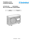
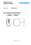
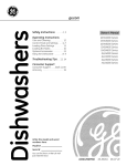
TECHNICAL DATA & SERVICE MANUAL ARGO HPL/SCL 0.8180.612.01 Pagina 1 06/2012 Table of contents Page A SPECIFICATIONS 1) Unit specifications 2) Major Component specifications 3 4 B OPERATING RANGE 6 C DIMENSIONAL DATA 7 D REFRIGERANT FLOW DIAGRAMS 8 E FUNCTIONS 1) System operation control 2) Cool Mode Operation 3) Heat Mode Operation 4) Auto Mode Operation 5) Dry Mode Operation 6) Fan Mode Operation 7) Auto Fan Speed 8) Forced Mode 9) Protection operations 10) Defrost 11) I FEEL Function 12) HI POWER mode 13) Heater resistance 14) NIGHT Function 15) LED OFF Function 16) Capacity test mode 17) Diagnostic 18) Address 19) Manual Unit Control and Led Indicators 20) Drain Pump 21) Safety thermostat 9 9 9 10 11 11 11 12 12 14 14 14 14 15 15 15 16 17 18 19 19 F ELECTRIC WIRING DIAGRAMS 20 G TROUBLESHOOTING 21 H CHECKING ELECTRICAL COMPONENTS 1) Measurement of Insulation Resistance 2) Checking Continuity of Fuse on PCS Ass'y 3) Checking Motor Capacitor 29 29 29 Pagina 2 SPECIFICATIONS A 1) UNIT SPECIFICATIONS UNIT MODEL ARGO HPL/SCL Power source PERFORMANCES Capacity (air BTU / h conditioner) kW m3 / h Air circulation (high/med/low) Moisture removal (high speed) Cooling l/h ELECTRICAL RATINGS Voltage rating V Available voltage range V Running Ampere (air conditioner) A Power input (air conditioner) W Power factor C.O.P FEATURES Controls / temperature control Control unit Timer Fan speed (air conditioner) Airflow direction Horizontal (Indoor) Vertical Air filter Compressor Refrig./Stand. Charge at shipmen R410A Refrigerant control Power noise level Air conditioner Hi/Me/Lo dB(A) (Indoor) Power noise level Air conditioner Hi/Me/Lo dB(A) (outdoor) Ducts diameter ( 2pcs ) mm Condensate drain system DIMENSIONS AND WEIGHT mm Height mm Widht mm Depht mm Holes diameter in the wall (2) kg Net weight 220 - 240 V 50 Hz COOLING HEATING 6310 7750 1,85 2,27 670-540-130 0,6 --220 - 240 198 - 264 3,2 710 0,96 2,61 3,2 715 0,97 3,17 Microprocessor / I.C. Thermostat Wireless remote control unit ON / OFF 24 hours and program 3 + Auto Manual Auto Washable, easy access Rotary (hermetic) DC inverter 650g Electronic expansion valve 65-62-59 65-63-61 162 By duct 735 839 260-280 162 49 Data can be changed without notice NOTE Rating conditions: Cooling: Heating: outside air temp.: 35° C DB, indoor air temp.: 27° C DB, 19° C WB outside air temp.: 7° C DB, 6° C WB, indoor air temp.: 20° C DB Pagina 3 2) MAJOR COMPONENT SPECIFICATIONS UNIT MODEL ARGO HPL/SCL CONTROLLER (PCB) Part No. Controls Control circuit fuse (F1) SWITCH INDICATOR ASSY Model Led color REMOTE CONTROL UNIT THERMISTOR (ROOM SENSOR) TH1 Resistance (at 25° C) kΩ THERMISTOR (INDOOR COIL SENSOR) TH2 Resistance (at 25° C) kΩ THERMISTOR (OUTDOOR AIR SENSOR) TH3 Resistance (at 25° C) kΩ THERMISTOR (COMP. DISCHARGE SENSOR) TH4 Resistance (at 25° C) kΩ THERMISTOR (OUTDOOR AIR SENSOR) TH5 Resistance (at 25° C) kΩ FAN & FAN MOTOR (FMI) Model Number / Diameter / Lenght No. of pole / rpm (230 V, high) rpm (230 V, high/ medium/ low) Power input (high) Power output (high) Coil resistance (at 25° C) mm W W Ω Safety device Setting Open Close °C μF VAC Run capacitor (C2) FAN & FAN MOTOR (FMO) Model Number / Diameter / Lenght No. of pole / rpm (230 V) rpm (230 V high/ medium /low) Nominal input (high/ medium7 low) Coil resistance (at 25° C) mm W Ω Safety device Setting Run capacitor (C1) Open Close °C μF VAC Pagina 4 sac dci ODU Microprocessor 6,3x32 - 12,5A PCB 384208055 TMR : blu - STB : orange - OPR : green SAC W-REM 10 ± 3% NTC (with brass pipe) 10 ± 5% NTC (with brass pipe) 10 ± 5% NTC (with brass pipe) 10 ± 5% 10 ± 5% UF2Q-21SC5P Cross-flow 1 / Ø100 / 515 2 2100/ 1760 / 730 68 31 BRN-WHT: 164 ±10% WHT-VLT: 69 ±10% VLT-ORG: 33 ±10% YLW-ORG: 74 ±10% YLW-PNK: 44 ±10% thermal protector 130 ± 8 79 ± 15 1,5 440 D2E 146 - HS99 - 99 Centrifugal 1 / Ø146 / 140 2 2220/ 1735/ 1345 167/ 118/ 104 BLU-BLK: 69± 5% GRY-BLK: 34± 5% WHT-GRY: 12± 5% BRN-WHT: 30± 5% (Internal bimetallic type) 150 ± 5K Autoreset 5 420 ARGO HPL/SCL UNIT MODEL COMPRESSOR (CM) Model Nominal cooling capacity oil: Freol a68ES-T or SUNICE T-68 Coil resistance (at 20° C) W cc Ω Ω Ω overload protection thermostat Rotary ( Hermetic) UG9A090FUAJP 2770 320 U-V : 2.78 V-W : 2.83 W-U : 2.73 software protection 115°C - Open °C Close °C Operating amp. (Ambient temp. 25° C) PUMP RELAY (RP) H62S Model 5A - 230V Contact rating 230 Coil supply VAC 17,2 ± 10% Coil resistance (20 °C) kΩ POWER RELAY (PR) OMRON G4F Model 20 A - 250 V Contact rating 12 Coil supply VAC 158 ± 10% Coil resistance (20 °C) Ω AUTOMATIC THERMOSTAT (AT) IMIT 541873 Model LS3 / 65°C type / switching point 15A - 250V Contact rating SAFETY THERMOSTAT (ST) External IMIT 541741 Model LS1 / 85°C type / switching point 16A - 250V Contact rating 4-WAY VALVE (20S) SQ-136 (Coil) SHF-4H-23U (Valve) Model AC 220/240 V, 50 Hz, 6W Coil rating 1440 ± 5% Coil resistance ELECTRONIC EXPANSION VALVE (EEV) ZCAM-MD12EX(Coil) ZCAM-BD15EX (Valve) Model DC 12 V Coil rating 46 ± 4% Coil resistance ELECTRICAL HEATER (RE) 05050A1 Model 230 voltage V 800 (+5% -10%) power W 66 (-5% +10%) resistance Ω (at 20°C) SAFETY FLOAT SWITCH (FS) P200AC-001 Model 230 Vac - 0,4 A contact rating V EMI FILTER (EF) 10SS4-1BA2-BR-Q2 Model 115/230 Vac , 50/60Hz rating voltage 10 rating current A (rms) INDUCTOR CBMF374125 Model 1.68 ± 10% Inductance mH 10 rating current A 0.13 ± 10% resistance Ω (at 20°C) Pagina 5 ARGO HPL/SCL UNIT MODEL CONDENSATE PUMP (PC) Model Rating Nominal intput Coil resistance (at 20° C) FLAP MOTOR (FLP) Type Model Rating Coil resistence (Ambient temp. 25°C) HEAT EXCHANGER COIL (EVAPORATOR) Coil Rows Fin pitch Face area HEAT EXCHANGER COIL (CONDENSER) Coil Rows Fin pitch Face area THERMOSTATIC VALVE DRAIN PAN Model Open Close Stroke B Ω 291036 220-240VAC~50Hz 5W - 0,05A 778 ± 8% Ω Stepping motor MP24GA1 DC 12V WHT-BLU (respectively 4 wires) : 380 ± 7% mm m2 Aluminium plate fin / copper tube 4 1,3 0,107 mm m2 Aluminium plate fin / copper tube 4 1,3 0,111 °C °C mm DP 25-1101-07 or DP 25-1107-01 4,4 15,5 5,1 OPERATING RANGE Cooling Heating Dry Temperature Maximum Minimum Maximum Minimum Maximum Minimum Indoor air intake temp. 32° C DB/ 23° C WB 10° C DB/ 6° C WB 27° C DB indoor room 30% R.H. 32° C BS/ 80% R.H. 10° C BS/ 80% R.H. Pagina 6 Outdoor air intake temp. 43° C DB -15° C DB 24° C DB / 18° C WB -15° C DB 43° C DB -15° C DB DIMENSIONAL DATA All dimensions are in mm C Pagina 7 D REFRIGERANT FLOW DIAGRAM ARGO HPL/SCL Pagina 8 E FUNCTIONS 1 System operation control The units receives the user input (fan speed, flap position etc) through remote controller which sends signal every time a button is pressed and in any case, automatically, every 5 minutes. During operation compressor speed can be subjected to change due to thermal load variations or protection activations but in any case: • The minimum time interval between an OFF and a ON operation is not lower than 3 minutes • The minimum operating time is not lower than 3 minutes • The maximum acceleration/deceleration rate is fixed at 20rpm /sec • During the start-up compressor speed increases according to a defined rule which is independent from the thermal load calculation. 2 Cool Mode Operation In Cooling Mode, the operation of the compressor (CM), Outdoor Fan (FMO) and Indoor Fan (FMI) are determined by: 1) the difference between the room air temperature (RAT) and the set point temperature (SPT) 2) the protection level at which the system is operating 3) the thermal load in the room NOTES In addition to the temperature difference of above, the operation of the main components (CM, FMO, FMI) is also controlled by protection function. The minimum off time of compressor is 3 minutes. The indoor fan can change speed only after it has operated at the same speed for 30 sec if in AUTO and 1 sec for the other settings (High, Med, Low). 3 Heat Mode Operation The Heating mode operation is similar to the Cooling mode operation. The CM, FMO and FMI are controlled by the same parameters. The FMI will not be turned on until the indoor coil temperature is warm enough to prevent the supply of cold air (see COLD DRAFT PREVENTION feature for details). The indoor fan can change speed only after it has operated at the same speed for 30 sec if in AUTO and 1 sec for the other settings (High, Med, Low). Pagina 9 4 Auto Mode Operation In Auto Mode, the unit switches automatically between the Auto Cooling and Auto Heating in order to maintain the room temperature (RAT) at the prescribed set point (SPT). The switching between the two modes is according to the above graph and following table COOLING ---> HEATING If -3°C ≤ Dt ≤-1°C and the compressor is off for more than 1 hour If Dt ≤ -3°C and compressor is off for more than 3 minutes HEATING ---> COOLING If 1°C ≤ Dt ≤ 3°C and the compressor is off for more than 1 hour If Dt ≥ 3°C and compressor is off for more than 3 minutes Dt = RAT - SPT Refer to the sections 1 COOLING MODE and 2 HEATING MODE for system operation details. Pagina 10 5 Dry Mode Operation Dry operation remove moisture from indoor air running, in cooling mode, at a low level without reducing the ambient temperature. This is done cycling ON and OFF the unit according to table below. ROOM TEMP DRY LEVEL ≥ SPT+2°C LEVEL 0 < SPT+2°C ≥ SPT-1°C < SPT-1°C ≥ 15°C < 15°C Operation according to COOLING mode CM on at constant speed FMO on at constant speed FMI switches between L and OFF every 30 seconds RV off CM switches 9 minutes off and 3 minutes on LEVEL 2 FMO switches 9 minutes off and 3 minutes ON FMI switches between L and OFF every 30 seconds RV off CM off DRY OFF ZONE FMO off FMI off RV off LEVEL 1 SPT = Set Point Temperature 6 Fan Mode Operation With this mode, the indoor fan is turned on while CM and FMO stay off all the time. The user can select between 3 speeds: HIGH, MEDIUM and LOW. 7 Auto Fan speed With this option selected, the indoor fan speed changes automatically according to the compressor speed as shown in the following graphs In heating, to prevent the supply of cool air, the FMI speed is setted as shown only if the indoor coil temperature ICT ≥ 34°C ( see COLD DRAFT PREVENTION feature for details ) If RAT goes over SET POINT by 1°C or less, for 1 hour, FMI is forced to LOW. If after 1 hour, RAT is still over SPT, FMI and compressor switch off. Pagina 11 8 Forced Mode In this mode the system operates (COOLING or HEATING mode – fixed settings) or is switched off by means of the MODE button on the pcb receiver. The operation modes can be selected pressing the button in a cyclic way (OFF COOL HEAT OFF…). The settings are: COOLING mode SET POINT temperature = 25°C FAN SPEED = HIGH FLAP POSITION = 3 HEATING mode SET POINT temperature = 21°C FAN SPEED = HIGH FLAP POSITION = 4 This special mode is useful if the remote controller is missing or unusable. When the remote controller operates, the function is automatically set off and the air conditioner follows the remote controller instructions 9 Protection operations 9.1 Freeze-up This protection prevents ice formation on the indoor coil heat exchanger. The protection is activated as soon as the indoor coil temperature ICT decreases and acts by decreasing the compressor speed The system exit this protection routine when ICT temperature rises above 5°C. 9.2 Cold draft This feature prevents the supply of cold air forcing the indoor fan to a speed which cannot be changed by the user. If the ICT temperature goes down 32°C (in descending) or does not reach 37°C (in rising), the speed fan is set as shown below. 9.3 Overheat internal exchanger This feature prevents the build up of high pressure in the indoor heat exchanger during heating operation As soon as the indoor coil temperature (ICT) increases, compressor speed is reduced in order to avoid heat exchanger overheating. System stops compressor operation when ICT reaches 60 °C Pagina 12 9.4 Overheat outdoor exchanger During cooling operation as soon as the outdoor coil temperature (OCT) increases, compressor speed is reduced in order to avoid heat exchanger overheating. System stops compressor operation when OCT reaches 65 °C 9.5 Compressor discharge temperature During operation, as soon as the discharge temperature increases, (CDT) compressor speed is reduced in order to avoid overheating of the motor. Compressor is stopped when CDT reaches 111°C 9.6 Compressor power-module overheating The module temperature, detected by a built-in thermistor, is always monitored by the control system and kept operating in a safe area. If temperature exceeds 100°C, operation is automatically stopped. 9.7 Compressor power-module overcurrent Operation is automatically stopped in case of current driven to each motor phase greater than 9A Pagina 13 10 Defrost The defrost process is controlled by a detection algorithm designed in order to mantain optimal utilization of the heat pump capacity especially during negative outdoor temperature conditions. • Compressor speed fixed • Expansion valve opening fixed • Outdoor fan switched off • Indoor fan controlled by cold draft prevention • Reversing valve switched off (cooling operation) • Minimum defrost time interval is 6 minutes • During HIGH POWER operation the defrost detection is ignored until this mode remains active • System exits defrost protection at least after 6 minutes and only if the temperature of 14°C is reached on outdoor coil. In any case it exits if at least 12 minutes are elapsed from the start of the defrost cycle. • After defrost, the compressor starts run after 3 minutes although the fan and the resistance switch on after 45 seconds. 11 I FEEL function As standard configuration the air conditioner operates detecting the room temperature through the sensor equipped in the wireless remote controller (icon I FEEL shown on the display). This feature provides a personalised environment since the temperature can be detected where the remote controller is located. It is possible to de-activate this option pressing the I FEEL button on the remote controller. In this case the I FEEL icon is no longer displayed and room temperature is detected through the sensor included in the indoor unit. 12 HI POWER mode When this mode is active the air conditioner operates without any power limitation. The compressor can use the full range of speed. During this mode, the operation led blinks with a long intermittence. To reset to normal mode (ECO mode), press three time the HI POWER / NIGHT MODE button on remote controller. After this switch, check that the operation lamp is constantly on. 13 Heater resistance The unit is equipped with a heater resistance which provide auxiliary power if required. There are 3 modes for heater operation: 13.1 Automode The heater resistance switches on only when are satisfied the following condition: 1) unit in automode operation 2) the required thermal load is higher than the maximum power that can be supplied by the heat pump circuit 3) outdoor air temperature lower than 2°C ( OAT<2°C ) 13.2 Auxiliary power in heating The heater resistance will switch on upon request of the user, in heating mode operation, by pressing the FILTER button on remote controller (icon FILTER shown on the display) 13.3 Fan heater In fan mode operation, the heater resistance will switch on, upon request of the user, by pressing the FILTER button on remote controller (icon FILTER shown on the display) In any case, the resistance will be turned off if reached the switching point of thermostats. Pagina 14 14 NIGHT Function When this setting is active indoor fan speed is automatically reduced in order to allow low noise operation.Temperature control acts in the same way as NORMAL MODE but after 60 minutes of operation the air conditioner modifies automatically the set-point temperature according to the following: •COOLING/DRY: +1°C •HEATING: - 2°C 15 LED OFF function This is a special function mode which can be selected by the user. With this option active the OPERATION, TIMER and STANDBY lamps are switched off even during operation (they activates only in case of diagnostic signaling). Before setting this mode, ensure that the icon 'FILTER' is not shown on display of remote controller and pressing, at the same for more than 5 seconds the IFEEL and FAN buttons To reset the normal lamps signaling, press at the same for more than 5 seconds the IFEEL and FAN buttons 16 Capacity Test mode This is a special operating mode used when testing the performance of the A/C. In this case the main components of the A/C (compressor , outdoor fan, indoor fan) operate at fixed settings. This option is activated by setting the remote controller as follows: -select filter on -select high power on -set the mode and temperature based on which kind of test is needed COOLING MODE: Setpoint = 10°C HEATING MODE: Setpoint = 32°C - press at the same time for more than 5 seconds IFEEL and FAN buttons In cooling capacity test mode the TIMER lamp blinks while the OPERATION lamp is on In heating capacity test mode the TIMER lamp blinks while the STANDBY lamp is on To reset the unit to normal mode, just turn off the power supply of the unit for at least 1 minute. Pagina 15 17 Diagnostic With this feature is possible to have a visual signal that a trouble is occurring. This mode is always active and the signalling is made through the display board LEDS . In case of no troubles the LEDS status follows its normal function. The detected troubles are showed to the user/technician using the 3 leds of the receiver For each fault there are different effects upon the operation of the A/C: NOTES The troubles are shown according to a priority list that is, in case of more than one trouble present, is always showed, at first, the one with the highest priority (1 2 3 etc). Sensor damaged means a situation where sensor is short-circuited or opened. In case of damaged sensors, the system (CM, FMO, FMI etc), if in OFF state, does not start. Priority 9 8 7 6 5 4 3 2 1 FAULT RAT probe damaged OAT probe damaged ICT probe damaged OCT probe damaged CDT probe damaged Compress. overcurrent Compressor overtemp. PFC fault Water level alarm LEDS status Effects LD1(tmr) LD2(stby) LD3(opr) blu org grn O F F ● F F System does not operate in cool, F O F dry and heat mode*. As soon as fault is cleared, system F ● F automatically restarts after 3 O F O minutes. During this time, the O F ● signalling is showed. ● F O ● F ● See paragraph 20. DRAIN PUMP O O F O = LED off F = LED blinking ● = LED on * If a fault occurred, the unit can operate only in fan and fan heater mode. In these modes, the fault signalling is suspended. Pagina 16 18 Address Changing the Address of the Air Conditioner In case of more than one air conditioner operating in the same room, it may be necessary to assign an address to each unit in order to avoid operation conflicts. Address is set acting on jumpers located on the unit PCB and on dip-switches of the remote controller. The PCB settings must match the corresponding ones on the wireless remote controller How to change address of the air conditioner Dip switch is located on the battery compartment. 1) Pull out the door and remove the batteries. 2) Set the switch SW1, SW2 and jumpers on PCB according to the table below (do not act on SW3 and SW4) 3) Insert the batteries and pull on the door As default switches SW1 and SW2 are in off status (remote controller factory state). JUMPERS (PCB) UNIT ADDESS JP 1 JP2 1 open 2 open 3 4 DIP SWITCH (REMOCON) JP3 1 2 closed closed off off on on open closed on off on on open closed open off on on on open open open on on on on As default switches SW1 and SW2 are in off status (PCB factory state). Pagina 17 3 4 19 Manual Unit Control and LED indicators The push button switch and the LED indicators on display panel let the user to control the unit operation without a R/C (Remote Controller). Their operations are provided below. Push Button Switch : Use to cycle the operation mode of the A/C unit among COOL, HEAT and OFF modes, without using the R/C. OPERATION BUTTON Every time this switch is pressed, the next operation mode is selected, in order: - Off => Cool mode => Heat mode => Off => … (for heat pump model) - The A/C will start in High fan speed. The temperature setting is 25°C for cooling and 21°C for heating mode. WARNING: the OFF position does not disconnect the power. Use the main power switch to turn off power completely. Led indicators : TIMER LAMP STANDBY LAMP 1. Lights up during Timer operation. 1. Lights up when the Air conditioner is connected to the power line and ready to receive the Remote Control command. 2. Blinks in combination with the other lamps in case of faults (see diagnostic paragraph) 1. Lights up in Operation mode. 2. Blinks in combination with the other lamps in case of faults OPERATION LAMP (see diagnostic paragraph) Pagina 18 20 Drain pump Pump operates when the unit is running in COOLING and DRY modes. The level detection is done through a float switch connected at the input FS (closed under normal condition, and opened when water overflows). System operation is according to the following chart: 21 Safety thermostat The unit is equipped with a double safety system to prevent overtemperature of the electrical heater The control of temperature is done throughby the automatic thermostat (AT) and safety thermostat (ST). The safety thermostat (ST), if activated, can be reset only manually by pushing the button, placed on the right side of the air inlet, behind the air filter. Pagina 19 F ELECTRIC WIRING DIAGRAMS ARGO HPL/SCL LEGENDA PCB FMI CM FMO RE C1-2 PC 20S EEV Controller Indoor fan motor Compressor motor Outdoor fan motor Electric heater Capacitor Condensate pump motor 4-way valve Expansion valve Pagina 20 SW-IND-ASSY TH1-2-3-4-5 ST AT EF FS FLP PR RP Indicator assy Thermistor safety thermostat automatic thermostat Emi filter Float switch Flap motor power relay pump relay G 1 TROUBLESHOOTING CHECK BEFORE AND AFTER «TROUBLESHOOTING» (A) Check power supply wiring. • Check the power supply wires are correctly connected. (B) Check power supply. • Check that voltage is in specified range (±10% of the rating). • Check that power is being supplied. • WARNING: If the following troubleshooting must be done with power supplied, be careful not to touch any uninsulated live part that can cause electric shock 2 CIRCUIT BREAKER TRIPS OR FUSE BLOWS. Reset the breaker without changing the unit settings. What’s happen? CASE 1 CASE 2 The breaker trips immediatly or resetting is not possible The breaker trips after few minutes There is a possibility of groun fault. Measure insulation resistance. If resistance value is < 1Mohm, insulation is defective Check insulation of EMI filter (EF) Check the following electrical parts: drain pump (PC) electric heater (RE) Replace faulty component Pagina 21 3 UNIT DOES NOT RUN. 3.1 - THERE IS NO SIGNALING LED ON UNIT Check power supply. Is power being supplied to wall receptacle? NO YES Check fuse on pcb. Is the fuse blown? The receiver assy is disconnected or defective NO YES Circuit breaker is tripped Power failure There is a possibility of short circuit Check EMI filter. Is it defective? NO Reset the breaker Wait for recovery or contact power company Check the following electrical parts: compressor fan motors inversion valve coil capacitors YES Change EMI filter (EF) PCB assy is defective EMI filter check up pin L-L’: lower than 0.5 ohm pin L-1: lower than 0.3 ohm pin N-N’: lower than 0.5 ohm pin N-2: lower than 0.3 ohm pin L-N: 2.2 Mohm pin L’-N’: 2.2 Mohm Pagina 22 3 UNIT DOES NOT RUN. 3.2 -THERE IS ONE LED ON AT LEAST AND THE UNIT DOES NOT RECEIVES THE REMOTE CONTROL SIGNAL Check the remote controller and PCB settings for address Try with another remote controller Receiver assy may be defective PCB assy may be defective 3.3 -THERE IS ONE LED ON AT LEAST AND THE UNIT RECEIVES THE REMOTE CONTROL SIGNAL Is the set point temperature appropriate NO Reduce the set point temperature in cooling mode or increase the set point in heating mode YES Is the unit in protection mode? YES Wait some minutes to restore normal condition NO Check unit leds signaling CASE 2 CASE 1 Normal leds configuration see section 4 There is a fault signaling see section 6 Pagina 23 3 UNIT DOES NOT RUN. 3.4- THERE IS ONE LED BLINKING AT LEAST TEMPERATURE SENSOR DAMAGED Check sensor connection and measure its resistance Replace the sensor COMPRESSOR OVERCURRENT/ OVERTEMPERATURE OR PFC FAULT WATER LEVEL ALARM Drain the water from the service tube There is a possibility of a short circuit Measure the resistance of compressor motor windings. Is it defective? YES Replace the compressor Is there any signaling of fault yet? YES NO Check compressor wire connection NO Check connection of float switch Replace the float switch Measure the resistance of inductor. Is it defective? NO Is the condensate drain tube obstructed NO Check drain pump (DP) connection NO YES Replace the inductor Pagina 24 PCB assy is defective Replace drain pump if defective YES Remove the obstruction 4 UNIT DOES NOT RUN OR RUN FOR FEW MINUTES AND NO FAULT IS DISPLAYED Before checking the unit with this test, follow these 4 steps 1) Turn off power supply 2) Wait 1 minute until the receiver leds switch off 3) Turn on power supply 4) Wait until the system starts (about 3 minutes) Pagina 25 5 AIR CONDITIONER OPERATES, BUT ABNORMALITIES ARE OBSERVED. Is the remote controller directly under the airflow of the unit? YES Change the position of the remote controller NO Is the unit in ECO mode? YES Set the unit in HI POWER mode YES Set fan speed in medium or high speed NO Is the fan motor set in low speed? NO Check the air filter. Is it clogged? YES Clean the air filter NO Check the expansion valve coil. Is it rightly connected and the resistance value correct? YES There is the possibilty of gas shortage NO Replace the expansion valve coil Pagina 26 6 ELECTRICAL HEATER DOES NOT WORK Before checking the unit with this test, follow these 3 steps 1) Switch the unit in FAN HEATER mode and fan on LOW speed for 3 minutes 2) Measure the power or current consumption directly from the power supply line Is the consumption much lower than the declared power input of resistance? YES Is the room temperature higher than 32°C YES Repeat the test with a temperature lower than 32°C NO Push reset button of safety thermostat and remeasure the power input. Does the resistance work? Check the air filter. Is it clogged? YES YES Clean the air filter NO Check if the airflow is adequate NO Measure the resistance of the heater. Is it defective? YES Replace the heater resistance NO Check continuty of safety thermostat (SF) and automatic thermostat (AT). Is there any defective thermostat? YES Replace the faulty thermostat NO Check pump relay(RP) and power relay (PR) Replace the faulty relay Pagina 27 Measure resistance of indoor fan motor (FMI) Change fan motor 7 AIR CONDITIONER OPERATES, BUT ABNORMALITIES ARE OBSERVED. 1 - OPERATION DOES NOT SWITCH FROM HEAT TO COOL AND FROM COOL TO HEAT Remote controller unit may be defective 8 Receiver assy may be defective Check the connection of reversing valve coil UNUSUAL NOISE IS OBSERVED Check that all the panel are fixed. Check the position of cushion rubbers under the compressor Check that internal tubes are not touching each other or with other components. Pagina 28 Check resistance of reversing valve coil H CHECKING ELECTRICAL COMPONENTS 1 Measurement of Insulation Resistance The insulation is in good condition if the resistance exceeds 1 Mohm a) Power Supply Wires Clamp the earthed wire of the power supply wires with the lead clip of the insulation resistance tester and measure the resistance by placing a probe on either of the power wires (fig.1). Then measure the resistance between the earthed wire and the other power wires (fig.1). b) Unit Clamp an alluminium plate fin or copper tube with the lead clip of the insulation resistance tester and measure the resistance by placing a probe on N terminal, and then on Lterminal the terminal plate (fig.2) c) Measurement of Insulation Resistance for Electrical Parts Disconnect the lead wires of the disired electric part from terminal plate, PCB assy, capacitor, etc. Similary disconnect the connector. Then measure the insulation resistance (fig.1 to 4). Refer to electric wiring diagram. NOTE If the probe cannot enter the poles because the hole is too narrow then use a probe with a thinner pin. 2 Checking Continuity of fuse on PCB assy Remove PCB assy from electrical component box (fig.5) Then pull out the fuse from PCB assy Check continuity of fuse by the multimeter (fig.6) 3 Checking Motor Capacitor Remove the lead wires from the capacitor terminals, and then place a probe on the capacitor terminals as shown in fig.7. Observe the deflection of the pointer, setting the resistance measuring range of the multimeter to the maximum value. The capacitor is "good" if the pointer bounces to a great extent and the gradually returns to its original position. The range of deflection and deflection time deffer according to capacity of the capacitor. Pagina 29 Via Varese, 90 - 21013 Gallarate - Va - Italy Tel. +39 0331 755111 - Fax +39 0331 776240 www.argoclima.it Pagina 30