1
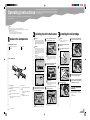
Image Scanner
Quick Installation Guide
Please read the Safety Information in the Operating Instructions before using this machine. It contains important
information related to USER SAFETY and PREVENTING MACHINE PROBLEMS.
Important
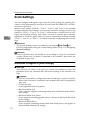
❒ When the machine is moved from a cold
location to a warm location, sudden temperature changes cause condensation inside of the scanner. Wait one hour or more
before turning on the scanner to allow the
condensation to evaporate.
Environments to Avoid
Important
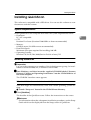
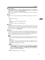
❒ Do not set up the scanner in any of the following types of locations. It may be the
cause of the malfunction.
• In a location exposed to direct sunlight
• In a location where the scanner will be subjected to blowing air or radiant heat, such
as near an air conditioner or heater
• In a location near other electronic devices,
such as a radio or television set
• In a location subject to extreme temperatures or humidity
• Near a humidifier
2004 10 G418-8600
G418-27
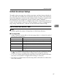
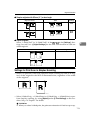
power supply rating:
AC 220-240V, 50/60Hz, 1A
Electrical Outlet Requirements
North America
G417-17/G418-17
Electrical Outlet Requirements:
AC 120V, 60Hz, min.10A
Europe
G418-27
Electrical Outlet Requirements:
AC 220-240V, 50/60Hz, min.5A
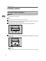
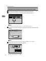
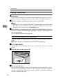
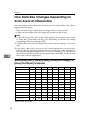
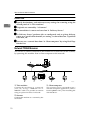
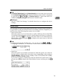
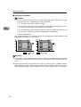
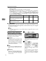
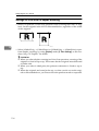
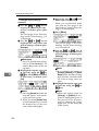
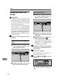
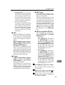
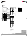
Space Required for Installing the
Scanner
Make sure that the scanner is in a location
where there is enough space to provide a
clearance as illustrated below, and also provide
a comfortable working area in the front.
ADC115S
1. 100mm (4inch) or more
ADC116S
2. 800mm (31.5inch) or more
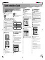
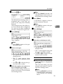
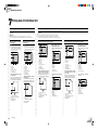
Quick Installation Guide (this sheet)
CD-ROM
Power Cord
Tool
Cleaning Cloth
Safety Instruction Sheet
Two Caps
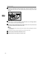
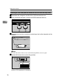
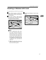
Remove the plastic bag. Lift the
scanner and move it to the place
where you want to install it.
Take out the scanner main unit.
ADC057S
Remove the tape.
Important
❒ Save the box and cushioning material in
which the scanner was packed so that they
can be used if it is necessary to transport
the scanner in the future.
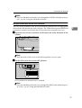
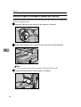
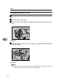
Open the automatic document feeder
(ADF) and remove the protective sheet
on the contact glass.
ADC058S
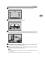
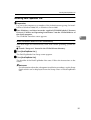
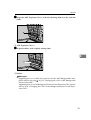
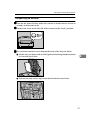
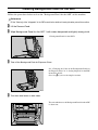
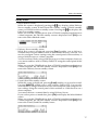
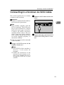
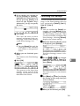
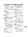
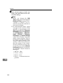
Disengaging the Lock
Remove two lock screws fixed on
the back of this machine.
ADC082S
Note
❒ Use a coin to remove the screws.
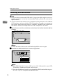
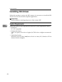
The holes left by the removed
screws are to be covered by the
caps. Put the leg stopper of the caps
into the holes vertically.
ADC084S
Turn the caps 90 degrees.
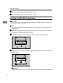
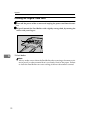
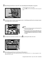
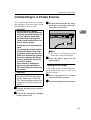
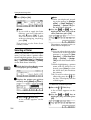
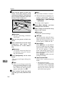
Lift the Pressure Panel, and carefully pull out the Background Panel
that is fixed with the Velcro.
ADC071S
The removed screws are to be kept
fixing on the back of the Pressure
Panel.
ADC086S
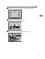
Return the removed Background
Panel to where it was.
Reference
❒ Regarding how to set the Background Panel,
please refer to a note on the back of the Pressure
Panel.
Set the lock lover to the “Unlock”
position.
ADC025S
○○○○○○○○○○○○○○○○○○○○○○○○○○○○○○○○○○○○○○○○○○○○○○○○○○○○○○○○○
ADC122S
Europe
G417-17/G418-17
power supply rating:
AC 120V, 60Hz, 2A
○ ○ ○ ○ ○ ○ ○ ○ ○ ○ ○ ○ ○ ○ ○ ○ ○ ○ ○ ○ ○ ○ ○ ○ ○ ○ ○ ○ ○ ○ ○ ○ ○ ○ ○ ○ ○ ○ ○
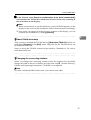
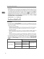
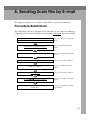
Recommended temperature and humidity
North America
CAUTION
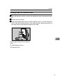
• This scanner weighs approximately 33 kg.
• Make sure to lift it carefully with two persons
or more so as to minimize physical strain.
Careless lifting, reckless handling or allowing it to drop down can cause injury.
• When transporting over long distances,
please consult an authorized dealer.
○ ○ ○ ○ ○ ○ ○ ○ ○ ○ ○ ○ ○ ○ ○ ○ ○ ○ ○ ○ ○ ○ ○ ○ ○ ○ ○ ○ ○ ○ ○ ○ ○ ○ ○ ○ ○ ○ ○ ○ ○ ○ ○ ○ ○ ○ ○ ○ ○ ○
Optimum Environment Conditions
Product Specifications
Check the contents of the box according to the following list. If one
or some items are missing, please
contact your sales or service representative.
○ ○ ○ ○ ○ ○ ○ ○ ○ ○ ○ ○ ○ ○ ○ ○ ○ ○ ○ ○ ○ ○ ○ ○ ○ ○ ○ ○ ○ ○ ○ ○ ○ ○ ○ ○ ○ ○ ○ ○ ○ ○ ○ ○ ○ ○ ○ ○ ○
CAUTION
• Keep the machine away from humidity and
dust. A fire or an electric shock might occur.
• Do not place the machine on an unstable
or tilted surface. If it topples over, it could
cause injury.
Connect the power cord to a power source with
the following specifications:
○○○○○○○○○○○○○○○○○○○
WARNING
• Make sure the wall outlet is near the machine
and easily accessible so that in event of an
emergency it can be unplugged easily.
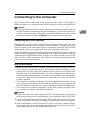
Power Connection
○○○○○○○○○○○○○○○○○○○○○○○○○○○○
The scanner location should be carefully
chosen because environmental conditions
greatly affect its performance.
○○○○○○○○○○○○○○○○○○○○○○○○○○○○○○○○○○○○○○○○○○○○○○○○○○○○○○○○○○○○○○○○○○○○○○○○○○○○○○○○○ ○ ○ ○ ○ ○
○○○○○○○○○○○○○○○○○○○○○○○○○○○○○○○○○○○○○○○○○○○○○○○○○○○○○○○
Confirming the Installation
Environment
Installing the
TWAIN/ISIS Driver
Installing the Scanner
○○○○○○○○○○○○○○○○○○○○○○
Checking the
Contents of
the Box
Preparation
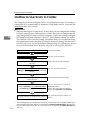
Log on to the computer as a member of the Administrators group, for installation to Windows
2000/XP, Windows Server 2003, or Windows NT
4.0.
This machine can be used both as a TWAIN
scanner and an ISIS scanner. A TWAIN driver
and its applications (DeskTopBinder Lite, etc)
are to be installed for the TWAIN scanner, and
an ISIS driver and its applications (QuickScan,
etc), are to be installed for the ISIS scanner.
Important
❒ Before starting "Found New Hardware Wizard,"
it is necessary to install the TWAIN/ISIS
driver. If the "Found New Hardware Wizard"
started before the installation, click the
[Cancel] button to discontinue the wizard
and then install the TWAIN/ISIS driver.
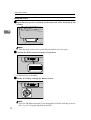
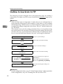
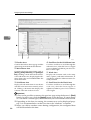
Start Windows, and then insert the
supplied CD-ROM labeled “Scanner
Driver(s), Utilities and Operating
Instructions ” into the CD-ROM drive
of the client computer.
The CD-ROM Launcher screen appears.
When installation does not
start automatically
A Auto Run might not automatically work with
certain operating system settings. In this
case, launch “Setup.exe” located in the CDROM root directory.
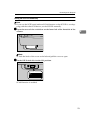
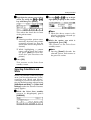
Click [TWAIN DRIVER] or [ISIS
DRIVER].
The installer of the TWAIN/ISIS driver starts.
Follow the instructions on the screen.
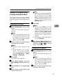
Power off the computer after the
installation is completed.
Note
❒ Don't power on the computer before the
procedure, “8. Detecting the Scanner”.
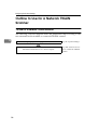
step
About TWAIN driver help
After you have installed the TWAIN driver, [(Model
Name) TWAIN V4] will be created under [Programs] of the [Start] menu. Help files for the
TWAIN driver can be displayed from here.
Notes on using the TWAIN scanner are provided
in “Readme.txt.” Be sure to read them before use.
ADC018S
Note
❒ Connect the SCSI cable to either one side of the
connectors.
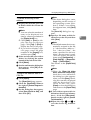
Open the cover of the switch box
on the lower left of the front side of
the scanner.
Note
❒ Push the knob of the cover to the left and pull
the cover to open.
Confirm the DIP Switch NO.3 is in
the OFF position.
ADC017S
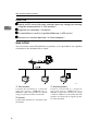
Connecting the SCSI Interface
(When the Scanner is not at the End
of the Daisy Chain)
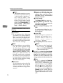
Shut down the computer and all of
the SCSI connected devices.
Daisy chain the computer, scanner
and SCSI connected devices.
ADC020S
Open the cover of the switch box
on the lower left of the front side of
the scanner.
Note
❒ Push the knob of the cover to the left and pull
the cover to open.
Set the DIP Switch NO.3 to the ON
position.
ADC021S
Built-in SCSI terminator is disabled.
SCSI synchronous transmission is enabled.
Set the SCSI ID by rotating the Rotary
Switch.
ADC017S
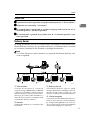
Connecting the USB Interface
Note
❒ Please use the recommended USB cable. Using
other cables might occur an irregular operation.
As for the recommended cables, please ask your
service representative.
Open the cover of the switch box
on the lower left of the frontside of
the scanner.
Note
❒ Push the knob of the cover to the left and pull
the cover to open.
Confirm the DIP Switch NO.2 is in
the ON position.
WARNING
• Do not use with a power source with a voltage
different from the specified voltage. Do not use
a power outlet with multiple devices plugged
in. These could create the risk of fire or electric shock.
• Avoid the use of an extension cord.
• Do not damage, break, twist or modify the
Power Cord. Placing heavy objects on the
cord, pulling on or bending it excessively can
damage the Power Cord, creating the risk of
fire or electric shock.
• Never touch or unplug the power plug with wet
hands. This can create the risk of electric
shock.
CAUTION
• When unplugging from an outlet, be sure to
grasp the plug when pulling. Never pull on
the cord. This could damage the cord creating the risk of fire or electrical shock.
Confirm that the power switch is set
to off.
ADC124S
ADC089S
Important
❒ Turning the power on leaving the lock lever
to the "Lock" position and/or turning the
power on without removing the screws could
result not only in failure in scanning but in
malfunction of this machine.
Push the power cord plug all the
way into the power connector on
this machine.
ADC026S
Note
❒ Be sure to use the power cord that comes with
this machine.
Insert the power plug into the power
outlet.
○○○○○○○○○○○○○○○○○○○○○○○○○○○○○○○○○○○○○○○○○
Daisy chain the computer, scanner
and SCSI connected devices.
Set the SCSI ID by rotating the Rotary
Switch.
A Set the DIP Switch NO.2 to the OFF position.
Confirm the lock screws on the back
of this machine are removed and the
holes left by the removed screws
are covered with the cap, and confirm that the lock lever is set to the
"Unlock" position.
Power on the scanner.
ADC125S
Start the computer.
The installation completes here for the
computer with the operation systems, Windows
95 and Windows NT4.0. For the computer with
other operation systems, “Plug & Play” detects
the scanner and the “Found New Hardware
Wizard” automatically starts.
In the Wizard, select [Search for a
suitable driver for my device [recommended]], and continue the
“Found Ne w Hardware Wizard” to
the end, according to the instruction on the displa y.
Note
❒ When an instruction to set the Windows system
CD-ROM appears on the display in the course
of the installation, follow the instruction accordingly.
❒ Even when “No approval of the logo test” appears on the display, you can continue the installation by clicking [continue].
ADC080S
Note
❒ If the DIP Switch NO.2 is set to OFF, set it to
ON. The scanner will not be detected if the
switch is set to OFF.
Connect the USB cable to the USB
connector.
Appendix: Turning the Power On/Off
Turning the Power On when
Connected with SCSI Interface
Turn the power on from the farthest devices from
the computer on the daisy chain. Start the
computer last.
Note
❒ The scanner will not be detected if you start the
computer first.
Turning the Power On when
Connected with USB Interface
There is no order to turn on the power when you
connect the scanner with USB Interface. You can
turn on either the scanner or the computer first.
○ ○ ○ ○ ○ ○ ○ ○ ○
Shut down the computer and all of
the SCSI connected devices.
SCSI synchronous transmission is enabled.
This section explains how to connect this
machine to a power source, using a bundled
AC power cord.
○○○○○○○○○○○○○○○○○○○○○○○ ○ ○ ○ ○ ○ ○ ○ ○ ○ ○ ○ ○ ○ ○ ○ ○ ○ ○ ○ ○ ○ ○ ○ ○ ○ ○ ○ ○ ○ ○ ○ ○ ○ ○ ○ ○ ○ ○ ○ ○ ○
Connecting the SCSI Interface
(When the Scanner is at the End of
the Daisy Chain)
A Set the DIP Switch NO.2 to the OFF position.
Changing the DIP Switch settings enables highspeed data transfer. This is available with SCSI
connection, the USB and the optional IEEE1394
connection cannot be used with this setting.
○ ○ ○ ○ ○ ○ ○ ○ ○ ○ ○ ○ ○ ○
❒ The SCSI interface of this unit is of the 50pin half-pitch (pin-type) type. Connect a
shielded SCSI-2 compliant with ANSI standards or a SCSI-3 (Ultra-SCSI) cable.
❒ It is possible that malfunction occurs or data
is lost when more than one SCSI ID's exists
simultaneously. Adjust the settings such that
the SCSI ID of this unit does not coincide
with the ID of another SCSI device.
❒ Keep the total length of the SCSI cable including the cable inside the PC to a maximum of 1.5m (4.9 feet) when using the
SCSI-3 (Ultra-SCSI) and 3m (9.8 feet) when
using the SCSI-2.
❒ Some combinations of the SCSI board of
your computer and daisychained peripherals
might cause an incorrect operation.
Please contact and ask your service
representative about the recommended
SCSI board.
❒ If you connect this unit to other SCSI devices
through a daisy chain, it may not work
properly. In this case, connect only this
unit to the computer.
Changing the DIP Switch settings enables highspeed data transfer. This is available with SCSI
connection, the USB and the optional IEEE1394
connection cannot be used with this setting.
When you do not use the USB
connection
○○○○○○○○○○○○○○○○○○○○○○○○○○○○○○○○○○○○○○○○○
Important
When you do not use the USB
connection
Detecting
the Scanner
Connecting the Power Code
○○○○○○○○○
You can connect the scanner to two computers
at the same time. One with the SCSI interface,
and one with the USB 2.0 interface. Though,
you cannot use the scanner at the same time
from two computers. Interfaces are switched
automatically when you change from one of the
computer to the other.
○○○○○○○○○○○○○○○○○○○○○○○○○○○○○○○○○○○○○○○○○○○○○○○○○○○○ ○ ○ ○ ○ ○ ○ ○ ○ ○ ○ ○ ○ ○ ○ ○ ○ ○ ○ ○ ○ ○ ○ ○ ○ ○ ○ ○ ○ ○ ○ ○ ○ ○ ○ ○ ○ ○ ○ ○ ○ ○ ○ ○ ○ ○ ○ ○ ○ ○
This scanner can be connected to the computer
with a SCSI and/or USB interface.
○○○○○○○○○○○○○○○○○○○○○○○○○○○○○○○○○○○○○○○○○○○○○○○○○○○○ ○ ○ ○ ○ ○ ○ ○ ○ ○ ○ ○ ○ ○ ○ ○ ○ ○ ○ ○ ○ ○ ○ ○ ○ ○ ○ ○ ○ ○ ○ ○ ○ ○ ○ ○ ○ ○ ○ ○ ○ ○ ○ ○ ○ ○ ○ ○ ○ ○
○○○○○○○○○○○○○○○○○○○○○○○○○○○○○○○○○○○○○○○○○○○○○○○○○○○○○○○○○○○○○○○○○
Connecting to the Computer
Turning the Power Off
There is no order to turn off the power. You can
turn off either the scanner or the computer first.
Copyright ©2004 G418-8600
Printed in Japan
GB
GB
EN
USA
ADC022S
Connect the other side of the cable
to the USB connector on your computer.
ADC019S
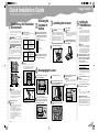
Quick Installation Guide
Image Scanner
Operating Instructions
Guide to Components
Setting up the Scanner
Installing Software
Setting Originals
Using the TWAIN Driver
Appendix
Read this manual carefully before you use this machine and keep it handy for future reference. For safe and correct use, be sure to read the Safety
Information in this manual before using the machine.
Introduction
This manual contains detailed instructions and notes on the operation and use of this machine. For your
safety and benefit, read this manual carefully before using the machine. Keep this manual in a handy
place for quick reference.
Two kinds of size notation are employed in this manual. With this machine refer to the inch version.
Important
Contents of this manual are subject to change without prior notice. In no event will the company be liable for direct, indirect, special, incidental, or consequential damages as a result of handling or operating the machine.
Caution
Certain options might not be available in some countries. For details, please contact your local dealer.
Some illustrations in this manual might be slightly different from the machine.
The supplier shall not be responsible for any damage or expense that might result from the use of parts
other than genuine parts from the supplier with your office products.
Do not copy or print any item for which reproduction is prohibited by law.
Copying or printing the following items is generally prohibited by local law:
bank notes, revenue stamps, bonds, stock certificates, bank drafts, checks, passports, driver's licenses.
The preceding list is meant as a guide only and is not inclusive. We assume no responsibility for its
completeness or accuracy. If you have any questions concerning the legality of copying or printing certain items, consult with your legal advisor.
Power Source
Color Scanner: 120V, 60Hz, 10A or more
Please be sure to connect the power cord to a power source as above.
Trademarks
Adobe, PostScript, and Acrobat are trademarks of Adobe Systems Incorporated.
QuickScan™ is a trademark of Pixel Translations and Captiva Software Corporation.
PixTools® and ISIS® are registered trademarks of Pixel Translations and Captiva Software Corporation.
Pentium is a registered trademark of Intel Corporation.
MS, Microsoft, and Windows are registered trademarks of Microsoft Corporation.
Other product names used herein are for identification purposes only and might be trademarks of their
respective companies. We disclaim any and all rights to those marks.
The proper names of the Windows operating systems are as follows:
• The product name of Windows® 95 is Microsoft® Windows® 95
• The product name of Windows® 98 is Microsoft® Windows® 98
• The product name of Windows® Me is Microsoft® Windows® Millennium Edition (Windows Me)
• The product names of Windows® 2000 are as follows:
Microsoft® Windows® 2000 Professional
Microsoft® Windows® 2000 Server
Microsoft® Windows® 2000 Advanced Server
• The product names of Windows® XP are as follows:
Microsoft® Windows® XP Home Edition
Microsoft® Windows® XP Professional
• The product names of Windows Server™ 2003 are as follows:
Microsoft® Windows Server™ 2003 Standard Edition
Microsoft® Windows Server™ 2003 Enterprise Edition
Microsoft® Windows Server™ 2003 Web Edition
• The product names of Windows® NT 4.0 are as follows:
Microsoft® Windows NT® Workstation 4.0
Microsoft® Windows NT® Server 4.0
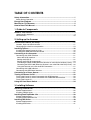
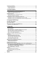
TABLE OF CONTENTS
Safety Information ................................................................................................. 1
Safety During Operation............................................................................................. 1
Energy Star Program ............................................................................................. 4
Manuals for This Scanner .....................................................................................5
How to Read This Manual .....................................................................................6
1. Guide to Components
Guide to This Scanner........................................................................................... 7
Understanding Indicators ........................................................................................... 9
DIP Switches............................................................................................................10
2. Setting up the Scanner
Confirmations Before the Setup......................................................................... 11
Location, Space and Environment ........................................................................... 11
Disengaging the lock for transportation....................................................................13
Installing Options................................................................................................. 16
Installing the Image-Processing Unit........................................................................ 16
Installing the IEEE1394 Interface Board .................................................................. 18
Connecting to the Computer .............................................................................. 21
Connecting with SCSI Interface ............................................................................... 21
About the SCSI Interface.......................................................................................21
Setting the SCSI ID ...............................................................................................22
Setting the SCSI ID Automatically .........................................................................23
Connecting the SCSI Cable (When the Scanner is at the End of the Daisy Chain) ...24
Connecting the SCSI Cable (When the Scanner is not at the End of the Daisy Chain) ...26
Using the Scanner only with the SCSI Connection ............................................... 27
Connecting with USB Interface ................................................................................28
Connecting with IEEE1394 Interface .......................................................................29
Connecting to a Power Source........................................................................... 31
Turning the Power On/Off ...................................................................................33
Turning the Power On when Connected with SCSI Interface ..................................33
Turning the Power On when Connected with USB/IEEE1394 Interface ..................33
Turning the Power Off .............................................................................................. 33
Using the Hard Reset Switch .............................................................................. 34
3. Installing Software
Installing TWAIN Driver .......................................................................................35
System Requirements.............................................................................................. 35
Installing TWAIN Driver............................................................................................36
Installing DeskTopBinder Lite ............................................................................38
System Requirements.............................................................................................. 38
Installing DeskTopBinder Lite .................................................................................. 39
Installing ISIS Driver ............................................................................................40
System Requirements.............................................................................................. 40
Installing ISIS Driver................................................................................................. 41
i
Installing QuickScan............................................................................................43
System Requirements.............................................................................................. 43
Installing QuickScan................................................................................................. 43
4. Setting Originals
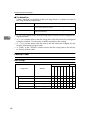
Sizes and Weights of Recommended Originals................................................45
Original Sizes Available for Auto Detection..............................................................46
Originals that Require Special Care.........................................................................47
Placing Originals..................................................................................................48
Placing the Original on the Exposure Glass.............................................................48
Placing the Originals in the ADF .............................................................................. 49
Changing the Color of the Background Panel ..................................................52
Changing the Color of the Background Panel for the ADF ...................................... 52
Changing the Color of the Background Panel for the Exposure Glass .................... 54
5. Using the TWAIN Driver
Procedure Breakdown......................................................................................... 57
Scanning Originals ..............................................................................................58
What You Can Do with the TWAIN Driver .......................................................... 60
Functions of the TWAIN Driver ................................................................................60
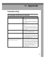
6. Appendix
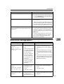
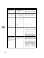
Troubleshooting...................................................................................................63
Error Indicators.........................................................................................................63
When the Original is Jammed or Double Fed in the ADF ........................................64
When the Originals are Not Fed Correctly ............................................................... 66
When Scanning is Not Performed as Expected .......................................................66
When an Error Message Appears............................................................................ 67
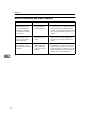
When in Installation and Other Problems.................................................................70
Cleaning................................................................................................................71
Cleaning the Original Table Cove ............................................................................ 72
Cleaning Under the Pressure Panel.........................................................................73
Cleaning Under the Background Panel....................................................................74
Cleaning Inside the ADF Cover................................................................................76
Cleaning the Ventilation Panel ................................................................................. 77
Moving and Transporting the Scanner .............................................................. 78
Moving Over Short Distances .................................................................................. 78
Transporting the Scanner.........................................................................................79
Disposing of the Scanner.................................................................................... 81
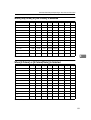
How Data Size Changes Depending on Scan Area and Resolution................ 82
When [Binary(Text)], [Binary(Photo)], [Binary(Auto Image)], or [Binary(Text/Photo)] is Selected...82
When [Gray Scale] or [256 Colors] is Selected............................................................ 83
When [8 Colors] or [8 Colors(Photo)] is Selected ........................................................ 83
When [16770K colors] is Selected.............................................................................. 84
Options ................................................................................................................. 85
Image Processing Unit Type B................................................................................. 85
IEEE1394 Interface Unit Type IS760 .......................................................................85
Specifications.......................................................................................................86
ii
INDEX......................................................................................................... 88
Safety Information
When using this machine, the following safety precautions should always be followed.
Safety During Operation
In this manual, the following important symbols are used:
R WARNING:
Indicates a potentially hazardous situation which, if instructions
are not followed, could result in death or serious injury.
R CAUTION:
Indicates a potentially hazardous situation which, if instructions are not
followed, may result in minor or moderate injury or damage to property.
1
R WARNING:
• Connect the Power Cord directly into a wall outlet and never use an extension cord.
• Disconnect the power plug (by pulling the plug, not the cable) if the power cable or plug
becomes frayed or otherwise damaged.
• To avoid hazardous electric shock or laser radiation exposure, do not remove any covers or
screws other than those specified in this manual.
• Turn off the power and disconnect the power plug (by pulling the plug, not the cable) if any
of the following conditions exists:
• You spill something into the equipment.
• You suspect that your equipment needs service or repair.
• Your equipment's cover has been damaged.
• Disposal can take place at our authorized dealer or at appropriate collection sites.
• Keep the machine away from flammable liquids, gases, and aerosols. A fire or an electric
shock might occur.
• Make sure the wall outlet is near the machine and easily accessible so that in event of an
emergency it can be unplugged easily.
• Do not use with a power source with a voltage different from the specified voltage. Do not
use a power outlet with multiple devices plugged in. These could create the risk of fire or
electric shock.
• Avoid the use of an extension cord.
• Do not damage, break, twist or modify the Power Cord. Placing heavy objects on the cord,
pulling on or bending it excessively can damage the Power Cord, creating the risk of fire or
electric shock.
• Never touch or unplug the power plug with wet hands. This can create the risk of electric
shock.
• Never remove any covers or screws other than those specified in this manual. The inside of
the scanner contains high-voltage components that can cause electrical shock. Have all inspections, adjustments, and repairs inside the scanner performed by an authorized dealer
only.
• Do not attempt to modify this scanner in any way. Modification can cause fire or electrical
shock.
2
R CAUTION:
• Protect the equipment from dampness or wet weather, such as rain, snow, and so on.
• Unplug the Power Cord from the wall outlet before you move the equipment.
While moving the equipment, you should take care that the Power Cord will not be damaged under the equipment.
• When you disconnect the power plug from the wall outlet, always pull the plug (not the cable).
• Do not allow paper clips, staples, or other small metallic objects to fall inside the equipment.
• For environmental reasons, do not dispose of the equipment or expended supply waste at
household waste collection points. Disposal can take place at an authorized dealer or at appropriate collection sites.
• The inside of the machine could be very hot. Do not touch the parts with a label indicating
the "hot surface". Otherwise it could cause a personal burn.
• Our products are engineered to meet high standards of quality and functionality, and we
recommend that you only use the expendable supplies available at an authorized dealer.
• Keep the machine away from humidity and dust. A fire or an electric shock might occur.
• Do not place the machine on an unstable or tilted surface. If it topples over, it could cause
injury.
• When unplugging from an outlet, be sure to grasp the plug when pulling. Never pull on the
cord. This could damage the cord creating the risk of fire or electrical shock.
• When disconnecting the power cord, always make sure to hold onto the plug. Do not pull
on the power cord itself. This can cause damage to the cord, fire or electrical shock.
• Be careful not to pinch your fingers when closing the Automatic Document Feeder (ADF).
• This scanner weighs approximately 72.8 lbs.
• Make sure to lift it carefully with two persons or more so as to minimize physical strain.
Careless lifting, reckless handling or allowing it to drop down can cause injury.
• When transporting over long distances, please consult an authorized dealer.
3
Energy Star Program
As an ENERGY STAR Partner, we have determined
that this machine model meets the ENERGY STAR
Guidelines for energy efficiency.
The ENERGY STAR Guidelines intend to establish an international energy-saving system for
developing and introducing energy-efficient office equipment to deal with environmental issues, such as global warming.
When a product meets the ENERGY STAR Guidelines for energy efficiency, the Partner shall
place the ENERGY STAR logo onto the machine model.
This product was designed to reduce the environmental impact associated with office equipment by means of energy-saving features, such as Low-power mode.
❖ Low-Power mode
This unit automatically lowers its power consumption at a predetermined
time (approximately 15 minutes) after the last operation was performed. To
operate the unit from this mode, see the instructions below.
• Method for clearing
• Put a document on the Original Table.
• Open the cover of the Automatic Document Feeder (ADF).
• Lift the Pressure Panel.
• Follow the instructions from the PC.
Note
❒ The Low-Power mode does not work in the following conditions.
• When an error occurs.
• When a document is placed on the Original Table.
❖ Specifications
Low-Power mode
4
Power consumption
Approx. 8W
Transitional interval
15 minutes
Manuals for This Scanner
The following manuals describe the operational and maintenance procedures of
this machine.
To enhance safe and efficient operation of this scanner, all users should read and
follow the instructions carefully.
❖ Quick Installation Guide
Describes how to install the scanner.
❖ Operating Instructions (this manual)
Provides all of the information how to install, set up, and use the scanner. This
manual is provided as a PDF file.
Note
❒ There is a CD-ROM that comes with this scanner.
5
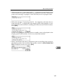
How to Read This Manual
Symbols
The following set of symbols is used in this manual.
R WARNING:
This symbol indicates a potentially hazardous situation that might result in
death or serious injury when you misuse the machine without following the instructions under this symbol. Be sure to read the instructions, all of which are described in the Safety Information section.
R CAUTION:
This symbol indicates a potentially hazardous situation that might result in minor or moderate injury or property damage that does not involve personal injury
when you misuse the machine without following the instructions under this
symbol. Be sure to read the instructions, all of which are described in the Safety
Information section.
* The statements above are notes for your safety.
Important
If this instruction is not followed, paper might be misfed, originals might be
damaged, or data might be lost. Be sure to read this.
Preparation
This symbol indicates information or preparations required prior to operating.
Note
This symbol indicates precautions for operation, or actions to take after abnormal operation.
Limitation
This symbol indicates numerical limits, functions that cannot be used together,
or conditions in which a particular function cannot be used.
Reference
This symbol indicates a reference.
[
]
Keys that appear on the machine's display panel.
[
]
Keys and buttons that appear on the computer's display.
{
}
Keys built into the machine's control panel.
{
}
Keys on the computer's keyboard.
6
1. Guide to Components
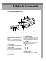
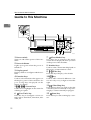
Guide to This Scanner
ADC002S
1. ADF (Automatic Document Feeder)
Allows you to automatically load multiple originals into this machine.
2. Paper Thickness Changeover Lever
When you scan the thick originals —
originals thicker than 128g/m2 (242.5bls)
— with the ADF, set the paper thickness
changeover lever to your side. After scanning, return the switch to the back side.
3. Original Table
Set originals here to be loaded into this
machine using ADF.
4. Output Table
The originals that have been loaded by
the ADF are output here after scanning.
5. Original Stopper
Stops the originals scanned by the ADF.
6. Rotary Switch
Use to set SCSI ID.
7. DIP Switches
Use to set the operation mode of this
scanner. ⇒ p.10 “DIP Switches”
8. Hard Reset Switch
This switch resets the power to the scanner. Use this switch when validate the
settings of the DIP Switches or the Rotary
Switch.
9. Indicators
Indicates the status of this machine. ⇒
p.9 “Understanding Indicators”
10. {Clear Modes}} key
Press this key to stop the manual scanning.
11. {Start}} key
Press this key to start the manual scanning
12. Power Switch
Turns this machine's power on and off.
7
Guide to Components
1
ADC003S
1. Pressure Panel
6. Lock Screw
Holds the originals down on the Exposure Glass.
This is to lock the scanning parts inside
when you transport this machine. Remove this screw when you set up this
machine.
2. Background Panel for Exposure
Glass
Panel to set the background color for the
original in black or white when you place
the original on the exposure glass. ⇒ p.54
“Changing the Color of the Background
Panel for the Exposure Glass”
7. USB 2.0 Interface Connector
3. ADF Exposure Glass
8. Lock Lever
Scans the originals when they are loaded
by the ADF.
Set this lever to the “Lock” position when
you transport this machine.
4. Exposure Glass
9. SCSI Interface Connector
Set the original here when you do not use
the ADF scanning.
Used for connection of a SCSI Cable.
5. ADF Cover
Used for an authorized customer engineer's maintenance only.
Open when clearing the misfed originals
or cleaning the rollers.
Used for connection of an USB cable. The
USB interface board is alternatively used
with the optional IEEE1394 interface
board.
10. SD Card Slot
11. Power Connector
For connection of the bundled AC power
code.
8
Guide to This Scanner
Understanding Indicators
This section explains how to interpret the indicators in front of this machine.
1
ADC126S
Indicators
*1
On
Blink
Low-Power mode
Off
Status of Power
Power On
Power Off
Machine Busy
Scanning operation
in progress *1
Documents in
place
Originals are set to
the ADF
No originals are
set to the ADF
Error detection
Error
No error or the
current status
Scan Wait SADF
When SADF mode or
during standby for
the manual scan
Sometimes it looks like blinking.
All indicators on: For a short while after you turned on the power, or pressed the
Hard Reset key.
All indicators blinking: System error. Contact your service representative.
Description of the Error indicator on: See p.63 “Error Indicators”
9
Guide to Components
DIP Switches
Change only the switches No. 1 to 3. Do not change the other switches.
1
ADC005S
SW No.
Function
OFF
ON
1
SCAM *1
disable
enable
2
SCSI synchronous transmission
enable
disable
3
SCSI termination
enable
disable
4
5
6
(system usage)
always OFF
Do not make changes.
7
8
*1
SCAM: SCSI Configured Automatically. Protocol to set SCSI ID automatically.
Important
❒ SCSI ID will not be configured even if you set SCAM to enable, when more
than one of this scanner with the SCAM function enabled are connected to the
daisy chain. In this case, disable the SCAM by setting the DIP Switch No.1
ON, and set the SCSI ID with the Rotary Switch.
❒ The USB and the optional IEEE1394 connection cannot be used when the SCSI
synchronous transmission is set. You can turn the DIP Switch No.2 OFF (SCSI
synchronous transmission enabled) when using the scanner only with the
SCSI connection.
❒ A malfunction with SCSI synchronous transmission may occur if you use a
SCSI cable longer than recommended, or a cable out of the standard. In that
case, turn the DIP Switch No.2 ON (SCSI synchronous transmission disabled).
❒ When the scanner is connected to the middle of the daisy chain, set the DIP
Switch No.3 ON.
10
2. Setting up the Scanner
This section explains how to setup the scanner to get it ready for use, and how
to make necessary connections.
Confirmations Before the Setup
Location, Space and Environment
❖ Location
R WARNING:
• Make sure the wall outlet is near the machine and easily accessible so that in event of an
emergency it can be unplugged easily.
R CAUTION:
• Keep the machine away from humidity and dust. A fire or an electric shock might occur.
• Do not place the machine on an unstable or tilted surface. If it topples over, it could cause
injury.
Place the scanner on a level, stable, vibrating-free surface.
• Allowable inclination of the surface for installation is within 0.2inch (when
measuring difference of heights between one end and the other of this machine, compared to a level surface).
❖ Space
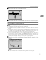
Make sure that the scanner is in a location where there is enough space to provide the clearance as illustrated below, and also provide a comfortable working area in the front.
ADC120S
1. 4 inch (100 mm) or more
2. 31.5 inch (800 mm) or more
11
Setting up the Scanner
❖ Environment
Important
❒ Do not set up the scanner in any of the following types of locations. It may
be the cause of the malfunction.
• In a location exposed to direct sunlight
• In a location where the scanner will be subjected to blowing air or radiant heat, such as near an air conditioner or heater
• In a location near other electronic devices, such as a radio or television
set
• In a location subject to extreme temperatures or humidity
• Near a humidifier
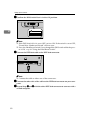
Set up the scanner in a location where the temperature and humidity will fall
within the ranges shown below.
2
ADC123S
Important
❒ Save the box and cushioning material in which the scanner was packed so
that they can be used if it is necessary to transport the scanner in the future.
❒ When the machine is moved from a cold location to a warm location, sudden temperature changes cause condensation inside of the scanner. Wait
one hour or more before turning on the scanner to allow the condensation
to evaporate.
12
Confirmations Before the Setup
Disengaging the lock for transportation
In this section, we explain how to disengage the lock after you take the scanner
out of the package for transportation.
A Remove two lock screws fixed on the back of this machine.
2
ADC082S
Note
❒ Use a coin to remove the lock screws.
❒ Be sure to remove the lock screws. Turning the power on without removing the screws could result not only in failure in scanning, but in malfunction of this machine.
B Cover both holes left by the removed screws with the caps.
A Put the leg stopper of the caps into the holes vertically.
ADC084S
B Turn the caps 90 degrees.
13
Setting up the Scanner
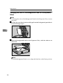
C The removed lock screws are to be kept on the back of the Pressure Panel
as follows:
A Lift the Pressure Panel and carefully pull out the Background Panel that
is fixed with the Velcro.
2
ADC071S
B The removed screws are to be kept fixing on the back of the Pressure
Panel.
ADC086S
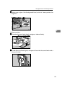
C Return the removed Background Panel to where it was.
Reference
Regarding how to set the Background Panel, please refer to the step B E of p.54 “Changing the Color of the Background Panel for the Exposure Glass”.
D Turn the lock lever on the back of this machine to the “Unlock” position.
ADC025S
14
Confirmations Before the Setup
Note
❒ Be sure to set the lock lever to the “Unlock” position. Turning the power
on leaving the lock lever to the “Lock” position could result not only in failure in scanning but in malfunction of the machine.
2
15
Setting up the Scanner
Installing Options
Installing the Image-Processing Unit
Important
❒ Touch any metallic material before touching the image-processing unit to remove static from your body.
2
Note
❒ Use the accessory tool to remove or fix the screws.
A Turn OFF the power to this product and disconnect all cables connected to
the product, including the power cable.
B Remove the three screws on the lower back surface of the product.
ADC009S
C Pull out the scanner control unit by pulling the black ribbon on the center
of the board.
ADC010S
Important
❒ The control unit is heavy. Please take care not to drop it when pulling it
out.
16
Installing Options
D Remove the seven screws on the cover of the scanner control unit.
2
ADC064S
E Open the cover of the scanner control unit.
ADC011S
F Connect the connector at the bottom surface of the image-processing unit to
the connector of the scanner control unit, and fix with one accessory screw.
ADC012S
G Check that it is connected tightly, check that there are no foreign objects
such as metal on the scanner control unit.
H Close the scanner control unit cover and fix with seven screws, then insert
the scanner control unit into the main unit.
Note
❒ Be sure to place the scanner on the level surface when inserting the scanner
control unit.
❒ Insert the scanner control unit till you see the screw holes.
17
Setting up the Scanner
I Fix the scanner control unit with three screws.
J Removed cables must connect in former state.
Installing the IEEE1394 Interface Board
Important
❒ Touch any metallic material before touching the IEEE interface board to remove static from your body.
2
Note
❒ The optional IEEE 1394 interface board is alternatively used with the USB interface board.
A Turn OFF the power to this product and disconnect all cables connected to
the product, including the power cable.
B Remove the three screws on the lower back surface of the product.
ADC009S
C Pull out the scanner control unit by pulling the black ribbon on the center
of the board.
ADC010S
Important
❒ The control unit is heavy. Please take care not to drop it when pulling it
out.
18
Installing Options
D Remove the seven screws on the cover of the scanner control unit.
2
ADC064S
E Open the cover of the scanner control unit.
ADC011S
F Remove the USB 2.0 interface board fixed with 6 screws.
ADC077S
19
Setting up the Scanner
G Connect the IEEE1394 interface board to the extension connector. Fix the
board with four accessory screws from inside, two accessory screws from
outside.
2
ADC014S
H Check that it is connected tightly, check that there are no foreign objects
such as metal on the scanner control unit.
I Close the scanner control unit cover and fix with seven screws, then insert
the scanner control unit into the main unit.
Note
❒ Be sure to place the scanner on the level surface when inserting the scanner
control unit.
❒ Insert the scanner control unit till you see the screw holes.
J Fix the scanner control unit with three screws.
K Removed cables must connect in former state.
20
Connecting to the Computer
Connecting to the Computer
This scanner can be connected to the computer with either a SCSI, USB, or
IEEE1394 interface. An optional board will be required to connect with IEEE1394.
Important
❒ Do not turn the power of the scanner ON before the software installation. If you
run the "Found New Hardware Wizard" beforehand, you will not be able to install the software correctly. When the "Found New Hardware Wizard" started
before the installation, click the [Cancel] button to discontinue the wizard.
2
Connecting with SCSI Interface
Standard, you can connect the scanner to two computers at the same time. One
with the SCSI interface, and one with the USB 2.0 interface. Though, you cannot
use the scanner at the same time from two computers. Interfaces are switched
automatically when you change from one of the computer to the other.
When the IEEE1394 interface board of the option is installed, you can connect the
scanner to three computers at the same time. One with a SCSI interface, and two
with the optional IEEE1394 interface. Though, you cannot use the scanner at the
same time from three computers. Interfaces are switched automatically when
you use any one of the computers.
About the SCSI Interface
Connection of this scanner to the SCSI (Small Computer System Interface) is as follows:
• This scanner is compliant for SCSI-3. You can daisy chain with SCSI-1/2 compliant devices as well. The SCSI connecter of this scanner is male 50pin halfpitch pin type. Use the shielded SCSI-2/3 cable compliant with ANSI (American National Standard Institute). Confirm in advance that some combination
of the SCSI cable and SCSI board on the computer may cause an incorrect
scanner operation.
• This scanner is compliant for SCAM (SCSI Configured Automatically). If you
use SCAM corresponding to SCSI board and driver for your computer, the
SCSI ID will be set automatically. ⇒ p.23 “Setting the SCSI ID Automatically”
• This scanner has a built-in terminator. Set the DIP switches properly when
you connect the scanner with the SCSI interface.
Important
❒ Using other cable than ANSI compliant SCSI-2/3 shielded cable, may possibly
bring about malfunction or electromagnetic wave interference above VCCI rules.
❒ Connect a SCSI cable shorter than 4.9feet (1.5m) for the SCSI-3 (Ultra-SCSI), and a
9.8feet (3m) cable for the SCSI-2, including the cable length inside your computer.
❒ Some combinations of the SCSI board of your PC and daisy-chained peripherals might cause an incorrect operation. Please contact and ask your service
representative about the recommended SCSI board.
21
Setting up the Scanner
Setting the SCSI ID
A Open the cover of the switch box on the lower left of the frontside of the
scanner.
2
ADC015S
Note
❒ Push the knob of the cover to the left and pull the cover to open.
B Confirm the DIP Switch No.1 to the OFF position.
ADC069S
SCAM function is disabled.
C Set the SCSI ID by rotating the Rotary Switch.
ADC017S
Note
❒ Press the Hard Reset Switch if you changed the SCSI ID while the power is
ON. ⇒ p.34 “Using the Hard Reset Switch”
22
Connecting to the Computer
Setting the SCSI ID Automatically
Note
❒ If you use the SCSI board without SCAM function or the SCSI ID is overlapping with the other SCSI device, set the SCSI ID manually.
A Open the cover of the switch box on the lower left of the frontside of the
2
scanner.
ADC015S
Note
❒ Push the knob of the cover to the left and pull the cover to open.
B Set the DIP Switch No.1 to the ON position.
ADC016S
SCAM function is enabled.
23
Setting up the Scanner
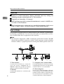
Connecting the SCSI Cable (When the Scanner is at the End of the Daisy Chain)
A Shut down the computer and all of the SCSI connected devices.
B Daisy chain the computer, scanner and SCSI connected devices.
2
ADC018S
Note
❒ Connect the SCSI cable to either one side of the connectors.
C Open the cover of the switch box on the lower left of the frontside of the
scanner.
ADC015S
Note
❒ Push the knob of the cover to the left and pull the cover to open.
D Set the DIP Switch No.3 to the OFF position.
ADC019S
24
Built-in SCSI terminator is enabled.
Connecting to the Computer
Note
❒ Press the Hard Reset Switch if you changed the SCSI ID while the power is
ON. ⇒ p.34 “Using the Hard Reset Switch”
2
25
Setting up the Scanner
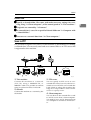
Connecting the SCSI Cable (When the Scanner is not at the End of the Daisy Chain)
A Shut down the computer and all of the SCSI connected devices.
B Daisy chain the computer, scanner and SCSI connected devices.
2
ADC020S
C Open the cover of the switch box on the lower left of the frontside of the
scanner.
ADC015S
Note
❒ Push the knob of the cover to the left and pull the cover to open.
D Set the DIP Switch No.3 to the ON position.
ADC021S
Built-in SCSI terminator is disabled.
26
Connecting to the Computer
Note
❒ Press the Hard Reset Switch if you changed the SCSI ID while the power is
ON. ⇒ p.34 “Using the Hard Reset Switch”
Using the Scanner only with the SCSI Connection
You can set the scanner to the SCSI synchronous transmission for high-speed
data transfer and shorten the total scan time. The USB and the optional IEEE1394
connection cannot be used when the SCSI synchronous transmission is set.
2
A Open the cover of the switch box on the lower left of the frontside of the
scanner.
ADC015S
Note
❒ Push the knob of the cover to the left and pull the cover to open.
B Set the DIP Switch No.2 to the OFF position.
ADC079S
SCSI synchronous transmission is enabled.
Note
❒ Press the Hard Reset Switch if you changed the DIP Switch while the power is ON. ⇒ p.34 “Using the Hard Reset Switch”
27
Setting up the Scanner
Connecting with USB Interface
Note
❒ Please use the recommended USB cable. Using other cables might occur an irregular operation. As for the recommended cables, please ask your service
representative.
2
❒ You can connect the scanner to two computers at the same time. One with the
SCSI interface, and one with the USB 2.0 interface. Though, you cannot use
the scanner at the same time from two computers. Interfaces are switched automatically when you change from one of the computer to the other.
A Open the cover of the switch box on the lower left of the frontside of the
scanner.
ADC015S
Note
❒ Push the knob of the cover to the left and pull the cover to open.
B Confirm the DIP Switch No.2 is in the ON position.
ADC080S
Note
❒ If the DIP Switch No.2 is set to OFF, set it to ON. If the switch is set to OFF,
"Found New Hardware Wizard" will not start. .
❒ Press the Hard Reset Switch if you changed the DIP Switch while the power is ON. ⇒ p.34 “Using the Hard Reset Switch”
28
Connecting to the Computer
C Connect the USB cable to the USB connector.
2
ADC022S
D Connect the other side of the cable to the USB connector on your computer.
Connecting with IEEE1394 Interface
Note
❒ The optional IEEE1394 interface board is required.
❒ An IEEE1394 cable is packed to be used for the optional IEEE1394 interface
board.
❒ An irregular operation might occur for the IEEE1394 interface board of some
PC. Please use the recommended IEEE1394 interface board for your PC. As
for the recommended boards, please ask you service representative.
❒ You can connect the scanner to three computers at the same time. One with a
SCSI interface, and two with the optional IEEE1394 interface. Though, you
cannot use the scanner at the same time from three computers. Interfaces are
switched automatically when you use any one of the computers.
A Open the cover of the switch box on the lower left of the frontside of the
scanner.
ADC015S
Note
❒ Push the knob of the cover to the left and pull the cover to open.
29
Setting up the Scanner
B Confirm the DIP Switch No.2 is in the ON position.
2
ADC080S
Note
❒ If the DIP Switch No.2 is set to OFF, set it to ON. If the switch is set to OFF,
"Found New Hardware Wizard" will not start. .
❒ Press the Hard Reset Switch if you changed the DIP Switch while the power is ON. ⇒ p.34 “Using the Hard Reset Switch”
C Connect the IEEE1394 cable to the IEEE1394 connector.
ADC023S
Note
❒ Connect the cable to either one of the connectors.
D Connect the other side of the cable to the IEEE1394 connector on your computer.
E Repeat Steps C and D with the other IEEE1394 connector to connect with a
second computer.
30
Connecting to a Power Source
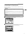
Connecting to a Power Source
This section explains how to connect this machine to a power source, using a
bundled AC power cord.
R WARNING:
• Do not use with a power source with a voltage different from the specified voltage. Do not
use a power outlet with multiple devices plugged in. These could create the risk of fire or
electric shock.
2
• Avoid the use of an extension cord.
• Do not damage, break, twist or modify the Power Cord. Placing heavy objects on the cord,
pulling on or bending it excessively can damage the Power Cord, creating the risk of fire or
electric shock.
• Never touch or unplug the power plug with wet hands. This can create the risk of electric
shock.
R CAUTION:
• When unplugging from an outlet, be sure to grasp the plug when pulling. Never pull on the
cord. This could damage the cord creating the risk of fire or electrical shock.
A Confirm that the power switch is set to Off.
ADC124S
B Confirm the lock screws on the back of this machine are removed and the
holes left by the removed screws are covered with the caps.
ADC088S
31
Setting up the Scanner
Important
❒ Be sure to remove the lock screws. Turning the power on without removing the screws could result not only in failure in scanning but in malfunction of this machine.
C Confirm that the lock lever located on the back of the machine is set to the
“Unlock” position.
2
ADC025S
Important
❒ Be sure to set the lock lever to “Unlock”. Turning on the power with the
lock lever set to “Lock” could result in failure in scanning or in malfunction
of this machine.
D Push the power cord plug all the way into the power connector on this machine.
ADC026S
Note
❒ Be sure to use the power cord that comes with this machine.
E Insert the power plug into the power outlet.
32
Turning the Power On/Off
Turning the Power On/Off
Important
❒ Do not turn the power of the scanner ON before the software installation. If
you run the “Found New Hardware Wizard” beforehand, you will not be
able to install the software correctly. When the “Found New Hardware Wizard” started before the installation, click the [Cancel] button to discontinue the
wizard.
2
ADC101S
1. Power Off
2. Power On
Turning the Power On when Connected with SCSI Interface
Turn the power on from the farthest devices from the computer on the daisy
chain. Start the computer last.
Note
❒ The scanner will not be detected if you start the computer first.
Turning the Power On when Connected with USB/IEEE1394
Interface
There is no order to turn on the power when you connect the scanner with USB
or IEEE1394 interface. You can turn on either the scanner or the computer first.
Turning the Power Off
There is no order to turn off the power. You can turn off either the scanner or the
computer first.
33
Setting up the Scanner
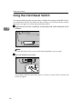
Using the Hard Reset Switch
You need to hard reset the scanner when validate the settings of the DIP Switches or the Rotary Switch. To hard reset the scanner, you can turn off the scanner
and turn it on again, or follow the procedures below.
A Open the cover of the switch box on the lower left of the frontside of the
2
scanner.
ADC015S
Note
❒ Push the knob of the cover to the left and pull the cover to open.
B Press the Hard Reset Switch.
ADC029S
The scanner will be in the same status as when you turn off the scanner and
turn it on again.
34
3. Installing Software
This machine can be used both as a TWAIN scanner and an ISIS scanner. A
TWAIN driver and its applications are to be installed for the TWAIN scanner,
and an ISIS driver and its applications are to be installed for the ISIS scanner.
Installing TWAIN Driver
When this machine is used as the TWAIN scanner; it is necessary to install the
TWAIN driver to be used for the TWAIN compliant applications.
Preparation
Start installation, retaining the power of the scanner OFF.
System Requirements
Install TWAIN Driver to the computer that meets the system requirements below.
(A “recommended” environment is for scanning documents by 16,770K Full color Mode.)
• Hardware
PC/AT compatible
• CPU
Pentium 200 MHz or faster (Pentium II 350 MHz or faster recommended)
• Memory
64 MB or more (128 MB or more recommended)
• Hard Disk Space
200 MB or more (1GB or more recommended)
• Display Resolution
800 × 600 pixels, 256 colors or higher (16,770K colors or higher recommended)
• Operating Systems
Windows 95(OSR 2 or later)/98/98 SE/Me/2000(Service Pack 4 or later)/XP,
Windows NT 4.0 (Service Pack 5 or later), Windows Server 2003
35
Installing Software
Installing TWAIN Driver
Preparation
Log on to the computer as a member of the Administrators group, for installation to Windows 2000/XP, Windows Server 2003, or Windows NT 4.0.
A Start the computer, retaining the power of the scanner OFF.
Note
❒ If the power of the computer turns ON, retaining the power of the scanner
ON, before driver installation, the "Found New Hardware Wizard" automatically starts. In this case, click [Cancel] button.
3
B Start Windows, and then insert the supplied CD-ROM labeled “Scanner
Driver(s), Utilities and Operating Instructions” into the CD-ROM drive of
the client computer.
The CD-ROM Launcher screen appears.
When installation does not start automatically
Auto Run might not automatically work with certain operating system settings.
A Launch “Setup.exe” located in the CD-ROM root directory.
C Click [TWAIN DRIVER].
The installer of the TWAIN driver starts. Follow the instructions on the
screen.
D Turn the power of the scanner ON.
ADC125S
E Re-start the computer.
The installation completes here for the computer with the operation systems,
Windows 95 and Windows NT4.0. For the computer with other operation
systems, "Plug & Play" detects the scanner and the "Found New Hardware
Wizard" automatically starts.
36
Installing TWAIN Driver
F In the Wizard, select [Search for a suitable driver for my device [recommended]],
and continue the "Found New Hardware Wizard" to the end, according to
the instruction on the display.
Note
❒ When an instruction to set the Windows system CD-ROM appears on the
display in the course of the installation, follow the instruction accordingly.
❒ Even when "No approval of the logo test" appears on the display, you can
continue the installation by clicking [Continue].
3
- About TWAIN driver help
After you have installed the TWAIN driver, [(Model Name) TWAIN V4] will be created under [Programs] of the [Start] menu. Help files for the TWAIN driver can
be displayed from here.
Notes on using the TWAIN scanner are provided in “Readme.txt”. Be sure to
read them before use.
- Changing the connecting interface
When you change the connecting interface from the interface first installed,
change the cable to the new interface and start from step D. "Scanner Driver(s),
Utilities and Operating Instructions" CD-ROM is not required.
Note
❒ Please confirm the DIP Switch when you connect each cable.
37
Installing Software
Installing DeskTopBinder Lite
DeskTopBinder Lite is a software with which you can manage various types of
file data, such as scanned images, or documents as if they were one file. This software is compatible with a TWAIN driver. You can use this software to scan documents with this scanner.
System Requirements
Install DeskTopBinder Lite to the computer that meets the system requirements
below.
• Hardware
PC/AT compatible
• CPU
Pentium 133 MHz or faster (Pentium II 266 MHz or faster recommended)
• Memory
48 MB or more (128 MB or more recommended)
• Hard Disk Space
Minimum free space required for installing: 70 MB
3
Note
❒ In addition to the space required for installation, the hard disk should have
at least 200 MB of free space for files.
• Operating Systems
Windows 98 SE/Me/2000(Service Pack 1 or later)/XP, Windows Server 2003
38
Installing DeskTopBinder Lite
Installing DeskTopBinder Lite
Preparation
Log on to the computer as a member of the Administrators group, for installation to Windows 2000/XP, or Windows Server 2003.
A Start Windows, and then insert the supplied CD-ROM labeled “Scanner
Driver(s), Utilities and Operating Instructions” into the CD-ROM drive of
the client computer.
The CD-ROM Launcher screen appears.
3
When installation does not start automatically
Auto Run might not automatically work with certain operating system settings.
A Launch “Setup.exe” located in the CD-ROM root directory.
B Click [DeskTopBinder Lite.]
The DeskTopBinder Lite Setup screen appears.
C Click [DeskTopBinder Lite].
The Installer of the DeskTopBinder Lite starts. Follow the instructions on the
screen.
Reference
For information about the subsequent installation procedure, see the Setup
Guide which can be displayed from the Setup screen of DeskTopBinder
Lite.
39
Installing Software
Installing ISIS Driver
When this machine is used as the ISIS scanner; it is necessary to install the ISIS
driver to be used for the ISIS compliant applications.
Preparation
Start installation, retaining the power of the scanner OFF.
System Requirements
3
Install ISIS Driver to the computer that meets the system requirements below.
• Hardware
PC/AT compatible
• Display Resolution
1024 × 768 pixels, 256 colors or higher (16,770K colors or higher recommended)
• Operating Systems
Windows 98/98 SE/Me/2000(Service Pack 4 or later)/XP, Windows NT 4.0
(Service Pack 6 or higher)
40
Installing ISIS Driver
Installing ISIS Driver
Preparation
Log on to the computer as a member of the Administrators group, for installation to Windows 2000/XP, Windows Server 2003, or Windows NT 4.0.
A Start the computer, retaining the power of the scanner OFF.
Note
❒ If the power of the computer turns ON, retaining the power of the scanner
ON, before driver installation, the "Found New Hardware Wizard" automatically starts. In this case, click [Cancel] button.
3
B Start Windows, and then insert the supplied CD-ROM labeled “Scanner
Driver(s), Utilities and Operating Instructions” into the CD-ROM drive of
the client computer.
The CD-ROM Launcher screen appears.
When installation does not start automatically
Auto Run might not automatically work with certain operating system settings.
A Launch “Setup.exe” located in the CD-ROM root directory.
C Click [ISIS DRIVER].
The installer of the ISIS driver starts. Follow the instructions on the screen.
D Turn the power of the scanner ON.
ADC125S
E Re-start the computer.
The installation completes here for the computer with the operation systems,
Windows 95 and Windows NT4.0. For the computer with other operation
systems, "Plug & Play" detects the scanner and the "Found New Hardware
Wizard" automatically starts.
41
Installing Software
F In the Wizard, select [Search for a suitable driver for my device [recommended]],
and continue the "Found New Hardware Wizard" to the end, according to
the instruction on the display.
Note
❒ When an instruction to set the Windows system CD-ROM appears on the
display in the course of the installation, follow the instruction accordingly.
❒ Even when "No approval of the logo test" appears on the display, you can
continue the installation by clicking [Continue].
3
- Changing the connecting interface
When you change the connecting interface from the interface first installed,
change the cable to the new interface and start from step D. "Scanner Driver(s),
Utilities and Operating Instructions" CD-ROM is not required.
Note
❒ Please confirm the DIP Switch when you connect each cable.
42
Installing QuickScan
Installing QuickScan
This software is compatible with a ISIS driver. You can use this software to scan
documents with this scanner.
System Requirements
Install QuickScan to the computer that meets the system requirements below.
• Hardware
PC/AT compatible
• CPU
Pentium II or faster (Pentium II 400 MHz or faster recommended)
• Memory
64 MB or more (128 MB or more recommended)
• Hard Disk Space
Minimum free space required for installing: 200 MB
• Operating Systems
Windows 98/98 SE/Me/2000(Service Pack 4 or later)/XP
3
Installing QuickScan
Preparation
Log on to the computer as a member of the Administrators group, for installation to Windows 2000/XP, or Windows Server 2003.
A Start Windows, and then insert the supplied CD-ROM labeled “Scanner
Driver(s), Utilities and Operating Instructions” into the CD-ROM drive of
the client computer.
The CD-ROM Launcher screen appears.
When installation does not start automatically
Auto Run might not automatically work with certain operating system settings.
A Launch “Setup.exe” located in the CD-ROM root directory.
B Click [QuickScan].
The Installer of the QuickScan starts. Follow the instructions on the screen.
Reference
For information about the subsequent installation procedure, see the Setup
Guide which can be displayed from the Setup screen of QuickScan.
43
Installing Software
3
44
4. Setting Originals
This chapter describes how to set an original to be scanned with this machine.
It is possible to set an original on the exposure glass or the ADF. To scan several
pages successively, using the ADF is convenient.
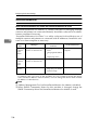
Sizes and Weights of Recommended
Originals
Where original
is set
Exposure glass
Original size (Main scanning × Sub scanning)
Up to 12″ × 17″
Original weight
Up to 297mm × 432mm
ADF
❖ Standard size
Maximum: 11” × 17”R, A3R
Minimum: B6JIS (Japanese Industrial Standard)S
40–157g/m2 (77–
298lbs)
❖ Non-standard size
• One side color
Maximum: 12” (297mm) × 24.8” (630mm)
Minimum: 2.7” (69mm) × 3.5” (90mm)
• One side monochrome
Maximum: 12” (297mm) × 78.7” (2000mm)
Minimum: 2.7” (69mm) × 3.5” (90mm)
• Both side color, Both side monochrome (The duplex model machine only)
Maximum: 12” (297mm) × 17” (432mm)
Minimum: 2.7” (69mm) × 3.5” (90mm)
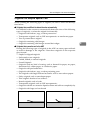
Note
❒ When you scan the thick originals — originals thicker than 128g/m2
(242.5bls) — with the ADF, set the paper thickness changeover lever to your
side. After scanning, return the lever to the back side.
❒ It may not be possible to scan a full color original even if it meets requirements of the chart above. See “Readme.txt” in the CD-ROM for details.
45
Setting Originals
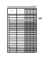
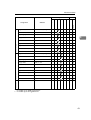
Original Sizes Available for Auto Detection
The scanner can detect the following document sizes automatically.
❖ When the Background Panel is Black
All of the original size can be detected from Exposure glass and ADF.
❖ When the Background Panel is White
• When set on the Exposure glass
Unable to detect automatically.
• When set on the ADF
11” × 17” (279mm × 432mm) R
8 1/2” × 14” (Legal, 216mm × 356mm) R
8 1/2” × 13” (216mm × 330mm) R
8 1/2” × 11” (Letter, 216mm × 279mm) R
8 1/2” × 11” (Letter, 279mm × 216mm) S
5 1/2” × 8 1/2” (216mm × 279mm) R
5 1/2” × 8 1/2” (216mm × 279mm) S
A3 (11.7” × 16.5”, 297mm × 420mm) R
B4JIS (10” × 14.3”, 257mm × 364mm) R
A4 (8.3” × 11.7”, 210mm × 297mm) R
A4 (8.3” × 11.7”, 210mm × 297mm) S
B5JIS (7.2” × 10”, 182mm × 257mm) R
B5JIS (7.2” × 10”, 182mm × 257mm) S
A5 (8.3” × 5.8”, 210mm × 148mm) S
B6JIS (7.2” × 5”, 182mm × 128mm) S
4
46
Sizes and Weights of Recommended Originals
Originals that Require Special Care
When scanning the following types of originals, be sure to follow the descriptions below.
❖ Originals that are difficult to detect the size automatically
It is difficult for the scanner to automatically detect the sizes of the following
types of originals, so select the original size manually.
• Originals with indexes, tags, or other protrusions
• Transparent originals such as OHP transparencies or translucent paper
• Text or picture dense original
• Originals containing solid images
• Originals containing solid images around their edges
4
❖ Originals that cannot be set in the ADF
Placing the following types of originals in the ADF can cause paper misfeeds
or result in damage to the originals. Place these originals on the exposure
glass instead.
• Stapled or clipped originals
• Perforated or torn originals
• Curled, folded, or creased originals
• Pasted Originals
• Originals with any kind of coating, such as thermal fax paper, art paper,
aluminum foil, carbon paper, or conductive paper
• Originals with perforated lines
• Originals with indexes, tags, or other projecting parts
• The originals with large frictional resistance such as non-carbon papers.
• Sticky originals such as translucent paper
• Thin originals that have low stiffness
• Bound originals such as books
• Transparent originals such as OHP transparencies
• Originals with ink or correction liquid on them and still not completely dry
• Originals with large curl on the end
ADC065S
47
Setting Originals
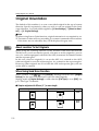
Placing Originals
Placing the Original on the Exposure Glass
Important
❒ Be careful not to pinch your fingers when closing the ADF.
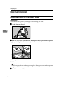
A Lift the Pressure Panel.
4
ADC030S
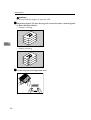
B With the side to be scanned facing down, place the original on the exposure
glass, and align it with the home position and scale.
ADC103S
1. Home position
2. Scale
Important
❒ Do not press down on the exposure glass. Strong pressure on the exposure
glass could cause it to break.
C Gently lower the ADF.
48
Placing Originals
Placing the Originals in the ADF
The ADF allows you to place multiple originals at one time.
❖ Precautions when placing an original in the ADF
• For information about the originals that cannot be placed in the ADF, see
p.47 “Originals that cannot be set in the ADF”.
•
•
•
•
Important
❒ Attempting to use unsuitable originals in the ADF can lead to a misfeed and
damage to the originals. Place such originals directly on the exposure glass.
Do not set originals in the ADF in excess of the upper limit mark.
In case the end of originals are curled too much to feed with the ADF, decrease the number of originals or adjust the curled end of originals straight.
See p.46 “Original Sizes Available for Auto Detection” for information
about the original sizes that can be detected automatically.
Fan the originals to get air between the sheets before setting them in the ADF.
4
A Adjust the stopper of the Output Table to the size of your originals.
ADC104S
1. stopper
Note
❒ Pull out the stopper and insert it to the other way to adjust the position of
the stopper when you are scanning originals shorter than 5.8” × 8.3”L or
4.1” × 5.8”K (A5L or A6K) in longways.
ADC033S
49
Setting Originals
Important
❒ Do not hold the stopper to open the ADF.
B Align the originals. To have the originals scanned in order, set the originals
in order illustrated below.
• Simplex scanning
4
ADC062S
• Duplex scanning
ADC063S
C Fan the originals and align them well.
50
Placing Originals
D Place the originals with first page on the top with the face up. Adjust the
side guides to the size of your originals.
ADC105S
4
1. Side guides
Note
❒ Adjust the original guide carefully by moving the root part of the original
guide located over the original tray ditch.
❒ Be careful not to drop any alien objects such as paper clip, dust, etc. into
the original tray ditch.
❒ Check that the ADF is closed.
E Set the paper thickness changeover lever to your side when you scan the
2
thick originals — originals thicker than 128g/m (242.5bls).
ADC078S
Note
❒ After scanning, return the switch to the back side.
51
Setting Originals
Changing the Color of the Background
Panel
Change the color of the Background Panel to enable auto original size detection
or scan in clear images.
Important
❒ Change the settings of the TWAIN driver from [Back.Panel] tab in [Initial Settings] of the driver dialog.
❒ Make sure that the color of the Background Panel for Exposure Glass, ADF
and settings made in [Back.Panel] tab on the TWAIN driver are same.
Note
❒ The size of the originals that can be automatically detected will be different
depending on the color of the Background Panel. ⇒ p.46 “Original Sizes
Available for Auto Detection”
4
❒ You can reduce the transparencies of the duplex printed originals by setting
the Background Panel to Black.
❒ To scan the transparent originals which is simplex printed, set the Background Panel to White.
Changing the Color of the Background Panel for the ADF
Preparation
Skip this procedure if you use the simplex scanner.
A Lift the Pressure Panel.
B Take off the Background Plate for Exposure Glass.
ADC035S
Reference
⇒ p.54 “Changing the Color of the Background Panel for the Exposure
Glass”
52
Changing the Color of the Background Panel
C Turn down blue levers on both sides.
ADC036S
The unit which stores the Background Panel for the ADF is drawn out.
D Push down a lever on the left, and change the color of the Background Pan-
4
el by rotating the screw on the right to the ∆mark position.
ADC037S
Note
❒ Turn the slit in the way shown in the illustration. Do not turn to the other
side.
❒ Turn the slit till you hear the click. Rotate the screw to the position of the
∆mark position, and confirm that the Background Panel color has totally
changed.
E Push back the unit which you drew out in step C by pushing both ends of
the unit.
ADC038S
53
Setting Originals
Changing the Color of the Background Panel for the Exposure
Glass
Note
❒ To change the color of the Background Panel for the Exposure Glass, reverse
the panel.
A Lift the Pressure Panel, and carefully pull out the Background panel that is
fixed with magic tapes.
4
ADC071S
B Place the Background Panel on the Exposure Glass, with the color to use
downside.
ADC072S
Note
❒ Set the Background Panel so as to align the blue line at the Home position.
54
Changing the Color of the Background Panel
C Align upper right of the Background Panel, with the home position for
originals.
ADC073S
4
1. Home position
D Close the Pressure Panel slowly, and press it down firmly.
ADC074S
E Lift the Pressure Panel again, and press all over the Pressure Panel with a
clean, soft cloth.
ADC075S
55
Setting Originals
4
56
5. Using the TWAIN Driver
This chapter describes the operations for scanning originals with the TWAIN
driver using DeskTopBinder Lite. In addition, some functions of the TWAIN
driver are introduced.
Procedure Breakdown
The following overview diagram shows the flow of the steps for scanning documents from a computer using the TWAIN driver.
Start a TWAIN-compliant
application.
Select and start
the TWAIN driver.
Menu may be different depending on the application
you use.
⇒ “Scanning Originals”A
Menu may be different depending on the application
you use.
⇒ “Scanning Originals”B—F
Place the originals.
⇒ “Scanning Originals”G
Make the scan settings.
⇒ “Scanning Originals”H
Click [Scan] on the TWAIN driver. ⇒ “Scanning Originals”I
Save the scanned image.
Menu and procedure may be different depending on
the application you use.
⇒ “Scanning Originals”J
Close the TWAIN compliant
application.
Menu and procedure may be different depending on
the application you use.
⇒ “Scanning Originals”K
57
Using the TWAIN Driver
Scanning Originals
This section explains how to scan originals using the TWAIN scanner function.
The procedure goes along with p.57 “Procedure Breakdown”.
A On the [Start] menu, point to [Program], point to [DeskTopBinder], and then
click [DeskTopBinder].
DeskTopBinder Lite starts.
B Click [Scanner Settings...] on the [Tools] menu.
[Scanner Settings] dialog box appears.
Note
❒ Check the settings in the [File format for scanned image(s)] area. Scanned data
will be saved by the format specified here.
C Click [Select Scanner Driver...].
5
The name of the scanner you installed with the TWAIN driver will be displayed in the [Source] list.
D Select the model name and then click [Select...].
The TWAIN driver for the scanner is selected, and the [Source] list dialog box
will be closed.
E Click [OK] on the [Scanner Settings] dialog box.
The [Scanner Settings] dialog box closes.
F On the [File] menu, point to [Add Document], and then click [Scan...].
After a short while, the dialog box of the TWAIN driver that operates the
scanner appears.
G Place the Originals.
Note
❒ Place the originals either on the Exposure Glass or on the ADF. See p.48
“Placing Originals” for details.
H Make the scan settings.
Note
❒ View the TWAIN driver help files for the details of making the scan settings and the preview function.
58
Scanning Originals
I Click [Scan...]
Note
❒ If you checked [Start from Scanner] on the TWAIN driver, press the {Start}
}
key after you clicked [Scan...].
The image is scanned. It will be displayed in the DeskTopBinder Viewer and
the TWAIN driver dialog will close.
Note
❒ With DeskTopBinder Lite, it is possible to edit and print scan files. For
more information about how to edit and print, see DeskTopBinder Lite
Help.
J Save the scanned image in DeskTopBinder Lite.
A On the [File] menu, click [Exit].
B Enter the file name, and then click [OK].
The image is stored in DeskTopBinder Lite, and DeskTopBinder Viewer
closes.
5
K Close DeskTopBinder Lite.
A On the [File] menu, click [Exit].
DeskTopBinder Lite closes.
59
Using the TWAIN Driver
What You Can Do with the TWAIN Driver
The following is an introduction to the various functions of the TWAIN driver:
Reference
For more information about these functions or other functions, see TWAIN
driver Help.
Functions of the TWAIN Driver
Functions
5
Explanation
Scan Mode
4 Basic modes
(Standard/Photo
/OCR/Filing),
User saved 100 scan
modes
You can call out and save the original Scan
Modes.
Orientation:
Standard 0 deg.
/Right 90 deg.
/180 deg.
/Left 90 deg.
You can rotate the image to have originals
scanned in correct orientation depending on the
place to set the originals. If you are scanning the
duplex printed originals, set the [Scan Settings:]
as well.
Comb./Series
Combine 2 pages to 1
/Combine 4 pages to 1
/divide to 2 pages
/Do not divide
/No combination or division
You can divide two-page spread originals to two
individual page images, or combine duplex
printed originals to a simplex one page image.
256 Colors
(in [Col./Grad])
←
Reduces 24bit color data to 8bit to make the data
size smaller.
Endorser
60
About
User set charactors
/Date/Counter:
You can add the information mentioned in the
left to the scanned images. You can change the
size and the fonts of the endorser.
ICM: (in
[Color Matching])
←
When you enable ICM, the TWAIN Driver will
match the color data according to the color profile.
Deskew
←
Detects and corrects the tilt of the text strings.
Start from Scanner
←
Press the {Start}
} key of the scanner to start scanning the originals.
Preview
←
You can confirm the settings you made for the
scanning images before scanning the originals.
SADF
←
Scanning starts when you set the originals on the
ADF. When you are scanning the originals which
are apt to be double fed, enable SADF and set the
originals one by one on the ADF.
What You Can Do with the TWAIN Driver
Functions
About
Explanation
Auto detect(Mixed-size)
/Auto detect(Uni-size)
/Various fixed form sizes
/Custom size
When the Background Panel is black, an optional
width and length of originals will be automatically detected for both ADF and Exposure Glass
by the [Auto detect(Mixed-size)] function.
Double Feed Detect Ultrasonic Wave
/Length
/Ultrasonic Wave+Length
/Off
While using ADF, it detects and notes a double
feeding. A new ultrasonic function to check
space between originals, in addition to the detection of original length, enables more reliable detection of the double feeding.
Original Size
5
61
Using the TWAIN Driver
5
62
6. Appendix
Troubleshooting
Error Indicators
The following table shows the meaning of error indicators of this machine, and
how to fix the errors.
ADC112S
Error description
—
—
—
—
❍
❍
—
❍
❍
❍
Solution
The ADF or ADF
cover is not fully
closed.
Close the ADF or
ADF cover.
An original is
jammed in the ADF.
Remove the jammed
original.
More than one sheet
of originals are fed to
the ADF simultaneously, or incorrect
feeding occurs.
Remove the double
feeding original.
System error
Contact your service
representative.
Remove the originals
from the Exposure
Glass, and then lift
up the ADF or its
cover.
: On
❍: Blinking
—: Off
Note
❒ When the indicators show a status that is not listed above table, turn off the
power of this machine, and then back on. If the indicators still show the same
status, note the status of the indicators and contact your service representative.
63
Appendix
When the Original is Jammed or Double Fed in the ADF
When the original jammed in or double fed to the ADF, remove the original by
the following procedure.
A Open the ADF cover and remove if the original is jammed.
ADC046S
B Remove the original if it is jammed in the cove of the Original Table.
6
ADC047S
Note
❒ You can easily remove the original by lifting the ADF a little.
C Lift the ADF and remove if the original is jammed.
ADC066S
64
Troubleshooting
D In case the jammed original is not found so far, follow the procedures below:
A Take off the Background Panel.
Reference
⇒ p.54 “Changing the Color of the Background Panel for the Exposure
Glass”
B Turn down blue levers on both sides.
ADC036S
The unit which stores the Background Panel for the ADF is drawn out.
C Remove the jammed original.
6
ADC067S
Note
❒ Regarding a small size original that cannot be set in the ADF, place it on
the Exposure Glass instead. ⇒ p.47 “Originals that cannot be set in the
ADF”
65
Appendix
When the Originals are Not Fed Correctly
A Remove the originals from the ADF.
B Lift the Pressure Panel or open the ADF cover.
ADC048S
Unusual conditions of the Original Table will be corrected.
C Shutdown the Pressure Panel or the ADF cover.
6
Note
❒ When you shut the ADF cover, please confirm the two magnets are fixed
on the magnet catch and the cover is closed tightly.
When Scanning is Not Performed as Expected
Condition
The scanned image is dirty.
Possible Cause and Required Action
• The Exposure Glass, the ADF Exposure
Glass, Background panel, Feed roller or
Original Roller is dirty.
• Clean the Exposure Glass, the ADF Exposure Glass, Background panel, Feed roller
or Original Roller. ⇒ p.71 “Cleaning”
The originals are damaged when fed to the
ADF.
• Set the paper thickness changeover lever
correctly or it may damage originals.
Please confirm the lever and the paper
thickness of the originals. When you scan
the originals thicker than 128g/m2
(242.5bls), turn the changeover lever on
your side (thick paper mode).
Image is distorted or out of position.
• The original was moved while scanning.
Do not move the original while scanning.
• The original was not pressed flat against
the exposure glass. Make sure that the original is pressed flat against the exposure
glass.
66
Troubleshooting
Condition
Possible Cause and Required Action
The scanned image is upside down.
• The original was placed upside down.
Place the original in the correct orientation,
or set the [Orientation:] on the TWAIN driver to the correct setting.
No image results from scanning.
• The original was placed with the front and
back reversed.
•
When the original is placed directly on the
exposure glass, the side to be scanned must
face down. When the original is fed via the
ADF, the side to be scanned must face up.
When the Background Panel is white, the scan- • Change the [Original Size:] to the standard
ning size will be 0.1inch longer than the actual
size from the automatic detection setting.
original size.
• When the original is a non-standard size,
please specify the original size by use of the
[Basic] tub
• Change background color to black, and
you can detect the same size of originals.
Please use black background for the
mixed-size in particular.
6
When an Error Message Appears
Message
Possible Cause
Required Action
• Check the cables and connectors to
• The TWAIN driver
Cannot find the
see if it is connected correctly.
cannot find the scanscanner.
ner.
•
Check the power source of the scanCheck if the
ner.
•
When
using
SCSI,
you
scanner main powhave
the
computer
• When using SCSI, turn on the power is on.
started before turning
on the scanner.
• It is set to SCSI synchronous transfer
mode. Use the scanner with SCSI asynchronous
transmission mode
when you use the
USB/IEEE1394 connection.
Scanner is not
ready.
Check the scanner
and the options.
• The scanner is busy
initializing, or etc.
• The ADF cover is
open.
er from the farthest device on the
SCSI daisy chain. Start the computer
last.
• Set the DIP Switch No.2 to ON and
push the Hard Reset Switch in the
switch box when you use the USB or
IEEE1394 connection.
• Wait for a while after turning on the
power of the scanner till it gets
ready.
• Check the ADF.
• The ADF is lifted.
Fatal error has
occurred in the
scanner.
• Hardware errors from • Note the error message and error
which recovery is imnumber and call the service reprepossible have ocsentative.
curred in the scanner.
67
Appendix
Message
Possible Cause
Error has occurred in the
scanner.
• There is an error in
parameter setting to
the scanner.
Error has occurred in the
scanner driver.
• There is an error in the • Restart the operating system.
driver, scanner, or in • If the same error occurs again,
the operating system.
please call the service representative.
Required library
module cannot be
found.
Please reinstall
the module.
• The library module
has not been found.
Insufficient mem- • The memory or the
virtual memory on
ory.
your computer is
Close all other
short.
applications,
then restart
scanning.
6
Required Action
Clear Misfeed(s)
in ADF.
• The misfed original is
jammed inside the
ADF.
• Reinstall the TWAIN driver.
• If the same error occurs again,
please call the service representative.
• Reinstall the TWAIN driver.
• Close applications unnecessary for
scanning.
• Expand the memory or the virtual
memory of your computer.
• Remove the misfed originals and
scan again. ⇒ p.64 “When the Original is Jammed or Double Fed in the
ADF”
• Remove the misfed originals and
clear the error. ⇒ p.66 “When the
Originals are Not Fed Correctly”
• See p.47 “Originals that cannot be
set in the ADF” and check if the
original is suitable for the ADF.
• The settings for the Background
Cannot detect the • Failed to detect the
original
size
automatPanel on the TWAIN driver is set to
paper size of the
ically.
Black even the panel is set to white
original.
on the exposure glass. Set the panel
Specify the scanto Black to use the auto detect funcning size.
tion. When the panel is set to White,
it is unable to auto detect the original size. To use the white side of the
panel, set [Background Panel] in the
[Back.Panel] tab in [Initial Settings] on
the TWAIN driver to [White background panel]. Then set [Original Size:]
manually. ⇒ p.52 “Changing the
Color of the Background Panel”
68
Troubleshooting
Message
Cannot continue
endorsing due to
the limit.
Possible Cause
Required Action
• The number of figures
exceeded or dipped
from the values set for
the endorser counter.
• The number of the counter has exceeded the value set in [Digit:] under
the [Endorser] tab. Check the number of the originals and set [Start:],
[Step:], and [Digit:].
• The number of the counter has
reached -1 when you set [Step:] under the [Endorser] tab to negative
value. Check the number of the
originals and set [Start:] and [Step:]
so the number of the counter ends in
higher values than 0.
Cannot add any
more scanning
mode.
• Maximum number of
the scanning modes is
registered.
• You can add a maximum of 100
scanning modes. Delete the modes
that you do not use.
Cannot specify
any more scanning
area.
• Maximum number of
the scanning areas is
registered.
• You can add a maximum of 100
scanning areas. Delete the areas that
you do not use.
Double Feed has
occurred.
Do you want to
continue scanning?
Set the originals
again and press
"Yes" to continue,
"No" to end.
• Double Feed (More
than 2 sheets of original was fed into the
ADF at once) has occurred and was detected.
• To continue scanning, replace the
double fed originals to the ADF and
Click [Yes]. Scanning restarts after
you click [Yes].
Cannot rotate the • Exceeded the maximum file size for the
original.
rotate function.
Lower the resolution and scan
again.
Cannot perform
Combine in the
current resolution.
Set the resolution to over ndpi and scan
again.
6
• To finish scanning, click [No].
• The double feeding is likely to occur
when the changeover switch is not
set correctly to the paper thickness
of the originals. When you scan the
regular thickness originals —originals thinner than 128g/m2
(242.5bls)— set the switch on the
back side (regular paper mode).
• Lower the resolution or the set the
scan area smaller and scan again.
• When combining the • Adjust the resolution to the disimages, the originals
played value.
will be scanned with
the lowest resolution
specified for the scanner. The resolution
displayed on the message will be the lowest
resolution available
for the combine function.
69
Appendix
When in Installation and Other Problems
Condition
6
70
Possible Cause
Required Action
The computer could not
find the drivers even
"Drivers and Utilities"
CD-ROM is selected in
the "Found New Hardware Wizard."
• Wrong Installation
of the hardware
and the software.
• First, install the TWAIN Driver from
"Scanner Driver(s), Utilities and Operating Instructions" CD-ROM. Then
start the "Found New Hardware Wizard." See p.35 “Installing Software” for
details.
The computer cannot detect the scanner when
they are connected by
USB or IEEE1394.
• SCSI synchronous
transmission is enabled.
• Set the DIP Switch No 2 to the ON position. Then, press the Hard Reset
Switch. See p.10 “DIP Switches” for
details.
The computer with Windows 2000/XP freezes
when scanning with USB
connection.
• Windows failed to
update the USB
driver when the
Service Pack is installed.
• Open the Device Manager. Uninstall
the USB Driver "Intel PCI to USB Enhanced Host Controller" and scan for
hardware changes. "Intel PCI to USB
Enhanced Host Controller" will be updated to the correct USB driver.
Cleaning
Cleaning
R WARNING:
• Never remove any covers or screws other than those specified in this manual. The inside of
the scanner contains high-voltage components that can cause electrical shock. Have all inspections, adjustments, and repairs inside the scanner performed by an authorized dealer
only.
• Do not attempt to modify this scanner in any way. Modification can cause fire or electrical
shock.
R CAUTION:
• When disconnecting the power cord, always make sure to hold onto the plug. Do not pull
on the power cord itself. This can cause damage to the cord, fire or electrical shock.
We recommend periodically cleaning the scanner to ensure that it is in optimum
operating condition.
Clean the rollers every three months, and the ventilation panel filter every 6
months. The cleaning period, however, varies by type and volume of originals
to be used. Glass is to be cleaned every time it gets dirty.
Glass will be dry-cleaned with the cleaning cloth packed. When you cannot remove the dirt with the cloth, clean it with water-dampened and tightly wrung
cloth. If you cannot remove the dirt even with the wet cloth, use a neutral detergent. After you removed the dirt, wipe off the detergent, and then dry the glass
thoroughly.
Rollers are to be cleaned first with a dry, soft cloth. When the dirt remained, then
clean it with water-dampened and tightly wrung cloth. If this is not enough,
wipe off the dirt with ethyl alcohol, clean with water-dampened cloth, and then
remove moisture thoroughly with dry cloth.
6
Important
❒ Do not use volatile chemicals such as benzene, paint thinner or spray with insecticides. This can cause deformation, discoloration and cracking.
❒ Wipe off the Automatic Document Feeder (ADF) with a dry, clean cloth when
there is dust or soiling present inside.
Note
❒ Please make good use of the packed cleaning cloth putting in its case, setting
on a place convenient to use. The case comes with a both side adhesive tape.
R CAUTION:
• Be careful not to pinch your fingers when closing the Automatic Document Feeder (ADF).
71
Appendix
Cleaning the Original Table Cove
A Turn off the power of the scanner and unplug the power cord from the outlet.
B Wipe all around the Feed Roller with a tightly wrung cloth, by turning the
roller with your fingers.
ADC106S
6
1. Feed Roller
Note
❒ Always make sure to clean the Feed Roller after scanning a document written in pencil or other material that is not firmly fixed to the paper. Failure
to clean the Feed Roller can cause soiling of the next document scanned.
72
Cleaning
Cleaning Under the Pressure Panel
A Turn off the power of the scanner and unplug the power cord from the outlet.
B Lift the Pressure Panel.
C Wipe the Background Panel, the ADF Exposure Glass 1, and the Exposure
Glass with the cleaning cloth or a dry and soft cloth, taking a good care of
the magic tapes not getting entangled in the cloth.
6
ADC107S
1. Background Panel for Exposure
Glass
2. ADF Exposure Glass 1
3. Exposure Glass
73
Appendix
Cleaning Under the Background Panel
Note
❒ The cleaning procedures below are not necessary for the simplex model.
A Turn off the power of the scanner and unplug the power cord from the outlet.
B Lift the Pressure Panel.
C Take off the Background Panel.
6
ADC035S
Reference
⇒ p.54 “Changing the Color of the Background Panel for the Exposure
Glass”
D Turn down blue levers on both sides.
ADC036S
74
Cleaning
E Wipe the ADF Exposure Glass 2 with the cleaning cloth or a dry and soft
cloth.
ADC108S
1. ADF Exposure Glass 2
F Wipe the rollers with a tightly wrung cloth.
6
ADC053S
1. Rollers
Reference
Regarding how to set back the store box for the ADF Background Panel,
please refer to the step E of p.52 “Changing the Color of the Background
Panel for the ADF”
Regarding how to set the Background Panel for the Exposure Glass, please
refer to p.54 “Changing the Color of the Background Panel for the Exposure Glass”.
75
Appendix
Cleaning Inside the ADF Cover
A Turn off the power of the scanner and unplug the power cord from the outlet.
B Open the cover of the ADF.
C Wipe the rollers with a tightly wrung cloth, by turning them with your fingers.
6
ADC110S
1. Rollers
D Wipe the rollers in the cove with a tightly wrung cloth, by turning them
with your fingers.
ADC111S
1. Rollers
Note
❒ When you shut the ADF cover, please confirm the two magnets are fixed
on the magnet catch and the cover is closed tightly.
76
Cleaning
Cleaning the Ventilation Panel
Please clean the filter and the ventilation panel in every six months. However,
please clean it properly when it gets dirty.
A Turn off the power of the scanner and unplug the power cord from the outlet.
B Open the ventilation cover panel on the left side of the ADF, and clean the
inside filter and the ventilation panel.
ADC056S
6
77
Appendix
Moving and Transporting the Scanner
R CAUTION:
• This scanner weighs approximately 72.8 lbs.
• Make sure to lift it carefully with two persons or more so as to minimize physical strain.
Careless lifting, reckless handling or allowing it to drop down can cause injury.
• When transporting over long distances, please consult an authorized dealer.
• Safety laws and regulations (including those stipulating radio wave regulations and material regulations) differ in each country. Use of this product and
its consumable supplies, etc. in foreign countries in violation of these regulations may be punishable by law.
• Information regarding measures for ensuring safe transport can be obtained
from an authorized dealer. However, packaging and transport are to be performed by the customer.
Moving Over Short Distances
A Turn off the power of the scanner and unplug the power cord from the out-
6
let.
B Disconnect all cables connected to the scanner.
C Transport the scanner.
ADC057S
Important
❒ Try to keep the scanner as level as possible during transport.
78
Moving and Transporting the Scanner
Transporting the Scanner
A Turn on the Power Switch. Allow the scanner to remain on for at least 20
seconds, and then turn it off.
B Set the Lock Lever on the left side of the scanner to the “Lock” position.
ADC068S
C Fix it with the two lock screws kept on the back of the Pressure Panel.
A Lift the Pressure Panel, and carefully pull out the Background Panel that
is fixed with the Velcro.
6
ADC071S
B Take out the lock screws kept on the back of the Pressure Panel.
ADC085S
79
Appendix
C Return the Background Panel to where it was.
Reference
Regarding how to set the Background Panel, please refer to the procedures B - E of p.54 “Changing the Color of the Background Panel for the
Exposure Glass”.
D Turn 90 degrees the caps that covered the holes for lock screws, and take
out it.
ADC087S
Note
❒ The removed caps are to be kept in a bag and transported together with
the machine, since they are used at the place where the machine is set
up.
6
E Fix tightly with the lock screws.
ADC083S
Note
❒ Use a coin to tightly fix the lock screws.
D Disconnect all cables connected to the scanner.
E Place the scanner in original box and transport.
Important
❒ This scanner is a precision device. Be careful so that it is not damaged during transport.
❒ Use the cushioning materials provided with the scanner at the time of purchase.
80
Disposing of the Scanner
Disposing of the Scanner
When you want to dispose of your scanner, contact your dealer or a service representative.
6
81
Appendix
How Data Size Changes Depending on
Scan Area and Resolution
Scan area and resolution determine the data size of a scanned data. The following general rules apply:
• High resolution (dpi) makes data size larger and scan area smaller.
• Large scan area makes data size larger and resolution (dpi) lower.
Note
❒ In the following tables, each of the values displays the memory size to store
as image data. Actual file sizes may vary depending on the file type setting
(single page, PDF or multi-page TIFF).
❒ A blank cell means that the combination of the relevant settings is not available.
❒ Even when a data size is shown in a cell, it may happen that you cannot perform a scanning operation with the relevant settings due to the limitation of
the TWAIN-compliant application you use for scanning. For information
about the maximum data size that the application can handle, see the manual
that comes with the application.
6
When [Binary(Text)], [Binary(Photo)], [Binary(Auto Image)], or
[Binary(Text/Photo)] is Selected
Scan Area
100dpi 200dpi 300dpi 400dpi 500dpi 600dpi 700dpi 800dpi
A3
235
943
2,121
3,772
-
-
-
-
B4
176
705
1,591
2,826
-
-
-
-
A4
117
470
1,061
1,886
2,946
4,247
-
-
B5
87
353
794
1,414
2,208
3,183
-
-
A5
58
234
528
939
1,469
2,116
2,876
3,759
B6
43
174
394
702
1,098
1,582
2,155
2,815
A6
29
117
264
468
734
1,058
1,437
1,880
11” × 17”
227
913
2,051
3,652
-
-
-
-
81”/2 × 14”
144
579
1,304
2,324
3,629
-
-
-
81/2” × 13”
134
538
1,211
2,158
3,370
-
-
-
81/2” × 11”
113
455
1,024
1,826
2,852
-
-
-
56
227
512
913
1,423
2,051
2,794
3,652
51/2” × 81/2”
Values: Data size in KB
82
How Data Size Changes Depending on Scan Area and Resolution
When [Gray Scale] or [256 Colors] is Selected
Scan Area
100dpi 200dpi 300dpi 400dpi 500dpi 600dpi 700dpi 800dpi
A3
1,888
7,552
16,993
30,210
-
-
-
-
B4
1,416
5,664
12,744
22,656
-
-
-
-
A4
944
3,776
8,496
15,105
23,601
33,986
-
-
B5
708
2,832
6,372
11,328
17,700
25,488
-
-
A5
470
1,881
4,234
7,527
11,761
16,936
23,052
30,108
B6
352
1,410
3,173
5,642
8,815
12,694
17,278
22,568
A6
235
940
2,117
3,763
5,880
8,468
11,526
15,054
11” × 17”
1,826
7,304
16,435
29,218
-
-
-
-
81/2” × 14”
1,162
4,648
10,458
18,593
29,052
-
-
-
81”/2 × 13”
1,079
4,316
9,711
17,265
26,977
-
-
-
81/2” × 11”
913
3,652
8,217
14,609
22,827
-
-
-
51/2” × 81/2”
456
1,826
4,108
7,304
11,413
16,435
22,370
29,218
6
Values: Data size in KB
When [8 Colors] or [8 Colors(Photo)] is Selected
Scan Area
100dpi 200dpi 300dpi 400dpi 500dpi 600dpi 700dpi 800dpi
A3
707
2,829
6,365
11,316
-
-
-
-
B4
529
2,116
4,773
8,480
-
-
-
-
A4
352
1,411
3,185
5,659
8,838
12,743
-
-
B5
263
1,061
2,383
4,244
6,625
9,550
-
-
A5
174
702
1,584
2,819
4,408
6,350
8,630
11,277
B6
130
524
1,183
2,107
3,295
4,748
6,465
8,447
A6
87
351
793
1,406
2,202
3,175
4,313
5,640
11” × 17”
682
2,739
6,155
10,957
-
-
-
-
81/2” × 14”
434
1,739
3,912
6,972
10,889
-
-
-
81/2” × 13”
403
1,614
3,633
6,474
10,111
-
-
-
81/2” × 11”
341
1,366
3,074
5,478
8,556
-
-
-
51/2” × 81/2”
169
682
1,538
2,739
4,270
6,155
8,384
10,957
Values: Data size in KB
83
Appendix
When [16770K colors] is Selected
Scan Area
6
100dpi 200dpi 300dpi 400dpi 500dpi
700dpi 800dpi
A3
5,663
22,655
50,977
90,628
-
-
-
-
B4
4,247
16,989
38,231
67,964
-
-
-
-
A4
2,831
11,327
25,486
45,314
70,802
101,954
-
-
B5
2,123
8,495
19,113
33,982
53,100
76,460
-
-
A5
1,411
5,645
12,701
22,581
35,283
50,807
69,154
90,324
B6
1,057
4,230
9,519
16,925
26,446
38,079
51,832
67,701
A6
705
2,822
6,350
11,289
17,639
25,401
34,577
45,162
11” × 17”
5,478
21,914
49,306
87,656
-
-
-
-
81/2” × 14”
3,486
13,945
31,376
55,781
87,158
-
-
-
81/2” × 13”
3,237
12,949
29,135
51,796
80,932
-
-
-
81/2” × 11”
2,739
10,957
24,653
43,828
68,481
-
-
-
51/2” × 81/2”
1,369
5,478
12,326
21,914
34,240
49,306
67,111
87,656
Values: Data size in KB
84
600dpi
Options
Options
In this section, we refer to the options for this machine.
Image Processing Unit Type B
Installation of this option enables the following visual image processing by use
of the TWAIN driver.
❖ Binary(Auto Image)
When you binary-scan an original mainly with text files, this machine automatically detects and scans an appropriate threshold value.
❖ Binary(Text/Photo)
Set when you scan an original consisting of both texts and photos. It scans
with binary, and automatically detects and scans the photos to represent a
para-intermediate tone (gray) with a black and white net-dot pattern.
❖ Select Range
Set when you Binary-scan an original consisting of both texts and photos. You
can set the photo part alone as the para-intermediate (gray) tone. For an original mainly occupied by photos, to the contrary, you can detect and scan the
original as a whole as the para-intermediate (gray) tone, setting the text part
alone as non-intermediate (gray) tone. The maximum number of ranges to
have partially different setting from the overall setting is 4.
6
IEEE1394 Interface Unit Type IS760
You can connect your PC to the IEEE1394 Interface board
Two IEEE1394 connectors are available, and you can connect a total of 3 PCs to
this machine together with another SCSI connector equipped.
Limitation
❒ The pre-installed USB 2.0 interface board is to be used exclusively.
Note
❒ You cannot use simultaneously two or more PCs connected. Connection is
automatically switched to either SCSI, IEEE1349-1 or IEEE1349-2.
85
Appendix
Specifications
Type
flatbed type color scanner with ADF
Scanning method
Fixed document scanning and moving document scanning
The duplex model enables scanning of both sides of an original simultaneously.
Scanning area
*1
❖ ADF
• One side color
Main direction: 12 inch (297 mm) Max., 2.7 inch (69 mm) Min.
Sub direction: 24.8 inch (630 mm) Max., 3.5 inch (90 mm) Min.
• One side monochrome
Main direction: 12 inch (297 mm) Max., 2.7 inch (69 mm) Min.
Sub direction: 78.7 inch (2000 mm) Max., 3.5 inch (90 mm) Min.
• Both side color, Both side monochrome (The duplex model machine only)
Main direction: 12 inch (297 mm) Max., 2.7 inch (69 mm) Min.
Sub direction: 17 inch (432 mm) Max., 3.5 inch (90 mm) Min.
❖ Exposure Glass
Main direction: 12 inch (297 mm) Max., 0.4 inch (10 mm) Min.
Sub direction: 17 inch (432 mm) Max., 0.4 inch (10 mm) Min.
6
Optical resolution
Main scanning: 400 dpi
Sub scanning: 400 dpi
Scanning grade
Input: 10 bits per pixel for each color
Output: 1 bit per pixel for monochrome and 8 bits per pixel for each
color
Scanning time of 1 line binary: 0.229 msec/line
color: 0.558 msec/line
ADF
Scanning
time *2
Simplex binary scanning: 75 ppm (8 1/2” × 11”R/ 200 dpi)
Duplex binary scanning: 122 ipm *3 (8 1/2” × 11”R/ 200 dpi Duplex model only)
Simplex full color scanning: 40 ppm (8 1/2” × 11”R/ 200 dpi)
Duplex full color scanning: 62 ipm *3 8 1/2” × 11”R/ 200 dpi Duplex model only )
Interface
Original
Stacks
200 sheets (8 1/2” × 11”, 64 g/m2)
Paper
Weights
40-157 g/m2 (77–298 lbs)
Standard
SCSI-3
USB 2.0
Option
86
IEEE1394 × 2 (Alternative with USB2.0)
Life
ADF: 3,000,000 scans, Flatbed: 600,000 scans, or 5 years
Operating environment
Temperature: 50-90 °F (10-32 °C), humidity 15-80 %
Power
120 V, 60 Hz
Specifications
Power consumption
During operation: 180 W
During standby: 50 W
During Low-Power mode: 8 W
Warm-up time
Max. 20 seconds
Transition time to the
Low-Power mode/
Recovery time from
the Low-Power mode
Transaction time: About 15 minutes
Dimensions
19.3 inch × 27.4 inch × 13 inch (490 mm × 695 mm × 332 mm) (W × D × H)
Weight
Simplex Scanner: Approximately 68.3 lbs (31 kg)
Recovery: 3 seconds or shorter
Duplex Scanner: Approximately 72.8 lbs (33 kg)
*1
*2
*3
The maximum scanning range varies by the level of resolution and grade.
Actual length of time for the scanning varies by your PC performance and environments.
ipm: images per minute
6
87
INDEX
A
ADF, 7
Jammed Originals, 64
Originals that cannot be set, 47
ADF Cover, 8
ADF Exposure Glass, 8
ADF Exposure Glass 1, 73
ADF Exposure Glass 2, 74
Auto Detection
Original Sizes, 46
Automatic Document Feeder, 7
E
Error Indicators, 63
Error Message and Required Action, 67
Error on the Original Table, 66
Exposure Glass, 8, 73
F
Feed Roller, 72
Filter, 77
G
B
Background Panel for Exposure Glass, 8, 73
Background Panel for the ADF
Changing the Color, 52
Background Panel for the Exposure Glass
Changing the Color, 54
C
Cleaning
ADF Exposure Glass 1, 73
ADF Exposure Glass 2, 74
Background Panel for Exposure Glass, 73
Exposure Glass, 73
Feed Roller, 72
Filter, 77
{Clear Modes}
} key, 7
Connecting
Computer, 21
IEEE1394, 29
IEEE1394 Board, 18
Image-Processing Unit, 16
Options, 16
Power Code, 31
SCSI, 21
USB, 28
D
Data Size, 82
DeskTopBinder Lite
Installation, 38
DIP Switches, 7, 10
Disposing, 81
88
Guide to This Scanner, 7
H
Hard Reset Switch, 7, 34
I
IEEE1394 Board, 18
IEEE1394 Interface Unit Type IS760, 85
Image-Processing Unit, 16
Image Processing Unit Type B, 85
Indicators, 7
In Normal State, 9
With Error, 63
Installing
DeskTopBinder Lite, 38
ISIS Driver, 40
QuickScan, 43
TWAIN Driver, 35
ISIS Driver
Installation, 40
J
Jam, 64
L
Lock Lever, 8
M
Moving, 78
O
Operating Instructions, 5
Options, 85
Originals Size, 45
Original Stopper, 7
Originals Weight, 45
Original Table, 7
Output Table, 7
P
Placing Originals
In the ADF, 49
On the Exposure Glass, 48
Power Connector, 8
Power Switch, 7
Pressure Panel, 8
T
Transporting, 78
Troubleshooting, 63
Turning the Power On/Off, 33
TWAIN Driver
Example of the Scanning, 58
Functions, 60
Installation, 35
Procedure Breakdown, 57
U
USB 2.0 Interface Connector, 8
Q
Quick Installation Guide, 5
QuickScan
Installation, 43
R
Resolution and Data Size, 82
Rotary Switch, 7
S
Scan Area and Data Size, 82
SCSI ID
Setting Automatically, 23
Setting Manually, 22
SCSI Interface Connector, 8
SD Card Slot, 8
Setting Originals, 45
Sizes Automatically Detected, 46
Specifications, 86
{Start}
} key, 7
Surroundings for Setup, 11
89
MEMO
90
EN
USA
G418-8602
In accordance with IEC 60417, this machine uses the following symbols for the main power switch:
a means POWER ON.
b means POWER OFF.
Copyright © 2004
Image Scanner Operating Instructions
EN USA G418-8602
Cleaning Background Panel for the ADF
Follow the procedures below to clean the "Background Panel for the ADF" of this machine.
Reference
❐ See "Cleaning" of the "6.Appendix" in the PDF manual for the details of cleaning the other parts of the machine.
1
2
Lift the Pressure Panel.
Wipe Background Panel for the ADF 1 with water-dampened and tightly wrung cloth.
1. Background Panel for the ADF 1
AID001S
3
Take off the Background Plate for Exposure Glass.
See "Changing the Color of the Background Panel for
the Exposure Glass" in "4. Setting Originals" in the PDF
manual for details.
Go to step 8 if you use the simplex scanner.
AID002S
4
Turn down blue levers on both sides.
The unit which stores the Background Panel for the ADF
is drawn out.
AID003S
5
Wipe Background Panel for the ADF 1with water-dampened and tightly wrung cloth.
1. Background Panel for the ADF 2
Go to step 7 if you are not cleaning the other background
color.
AID004S
6
Push down a lever on the left, and change the color of the Background Panel by rotating the screw
on the right to the ∆ mark position.
Note
❐ Turn the slit in the way shown in the illustration. Do
not turn to the other side.
❐ Turn the slit till you hear the click. Rotate the screw
to the position of the ∆ mark position, and confirm
that the Background Panel color has totally
changed.
AID005S
7
Push back the unit which you drew out in step
4 by pushing both ends of the unit.
AID006S
8
Set the Background Panel for the Exposure Glass back on.
See "Changing the Color of the Background Panel for the Exposure Glass" in "4. Setting Originals" in the
PDF manual for details.
Copyright© 2004 Printed in Japan EN USA G418-8620
Network Scanning Unit Type A
Quick Installation Guide
Please read the Safety Information in the Operating Instructions before using this machine. It contains important information related to
USER SAFETY and PREVENTING MACHINE PROBLEMS.
AC Adaptor
Safety Instruction Sheet
Wireless LAN Card cover
Ferrite Core (Europe only)
Remove the plastic bag. Lift this machine and move it to
the place where you want to install it.
WARNING
• Confirm that the wall outlet is near the machine and freely accessible, so that in event of an emergency, it can be unplugged easily.
• Only connect the machine to the power source described on this sheet.
• Avoid multi-wiring.
• Do not damage, break or make any modifications to the power cord.
Do not place heavy object on it, pull it hard or bend it more than
necessary. These actions could cause an electric shock or fire.
CAUTION
• Keep the machine away from humidity and dust. A Fire or an electric
shock might occur.
• Place the machine on a strong and level surface. Otherwise, the
machine might fall and cause personal injury.
• If you use the machine in a confined space, confirm that there is a
continuous flow of air.
○ ○ ○ ○ ○ ○ ○ ○ ○ ○ ○ ○ ○ ○ ○ ○ ○ ○ ○
The Machine's location should be carefully chosen because
environmental conditions greatly affect its performance.
Recommended temperature and humidity
%RH 10 C 80%
80
15 C
70%
60
40
15 C
30%
20
10 C 15%
10
27 C 80%
25 C
70%
32 C 15%
20
77 F
70%
50
60
89.6 F
54%
77 F
30%
89.6 F 15%
50 F 15%
20
C
30
80.6 F 80%
59 F
30%
40
32 C
54%
25 C
30%
%RH 50 F80%
80
59 F
70%
60
70
Possible operation range
80
90
F
Recommended range
The machine must be level within 5 mm,0.2" both front to rear
and left to right.
TDLH140E
Environments to Avoid
❒ Locations exposed to direct sunlight or strong light
❒ Dusty areas
❒ Areas with corrosive gases
❒ Areas excessively cold, hot, or humid
❒ Locations near an air conditioner or humidifier
❒ Locations near other electronic equipment
❒ Locations where the scanner might be subjected to frequent strong
vibration
G829-8600
Power Connection
Connect the power cord to a power source with the following specifications:
Product Specifications
North America
G829-17 power supply rating:
AC 120V, 60Hz
Europe/Asia
G829-27 power supply rating:
AC 220-240V, 50/60Hz
Electrical Outlet Requirements
North America
G829-17 Electrical Outlet Requirements:
AC 120V, 60Hz, min.2A
Europe/Asia
G829-27 Electrical Outlet Requirements:
AC 220-240V, 50/60Hz, min.2A
Connecting to a Scanner
via SCSI Cable
Optimum Environment Conditions
○○○○○○○○○○○○○○○○○○○○○○○○○○
○○○○○○○○○○○○○○○○○○○○○○○○○○○○○○○○○○○○○○○○○○○○○○○
Where to Put the Machine
Important
❒ Prepare a marketed SCSI cable before connection procedures.
Note
❒ This machine complies with the SCSI-2 standard. The SCSI interface on this machine has a 50-pin half-pitch (pin type) connector.
Connect an ANSI-compliant shielded SCSI-2 cable to this machine.
Note that some combinations of cables and the devices may not
work together properly, so check this carefully.
❒ Only one scanner can be connected to this machine.
Assign a SCSI ID to one of the numbers from 0 to 6.
Note
❒ The SCSI ID of this machine is fixed to 7 and cannot be changed.
❒ Follow the instructions of the manual of your scanner to connect to
this machine for how to change the SCSI ID of your scanner.
Connect a SCSI cable to this machine.
ZKJH050J
Connect the other end of the SCSI cable to the SCSI
port of a scanner.
○○○○○○○○○○○○○○○○○○○○○○○○○○○○○○○○○○○○○○○○○○○○○○○○○○○○○○○○○○○
Quick Installation Guide(this sheet)
CD-ROM
Power Cord
○ ○ ○ ○ ○ ○ ○
○○○○○
Check the contents of the box according to the following list. If any items are missing, please contact your
sales or service representative.
Important
❒ Use a 100BASE-TX (category 5) or10BASE-T network cable when
you connect this machine to a network.
Reference
See "Using Wireless LAN" in the Operating Instructions when using
an optional wireless LAN card
With the network cable you use for connection, create
A) away from an end of
a single loop about 15cm (6”)(A
the cable, and then attach the ferrite core that comes
with this machine as illustrated below.
Note
❒ Skip this step when you use this machine in North America.
Insert the network cable’s end to the network interface
connector of this machine.
ZKJH060J
Insert the other end of the network cable to an appropriate
connector of a network device, such as an Ethernet hub.
Connecting to a
Power Source
○○○○○○○○○○○○○○○○○○○○○○○○○○○○○○○○○○○○○○○○○○○○○○○○○○○○○○○○○○○
Connecting to a
Network
Unpacking the Machine and Checking the
Contents of the Box
WARNING
• Do not use with a power source with a voltage different from the
specified voltage. Do not use a power outlet with multiple devices
plugged in. These could create the risk of fire or electric shock.
• Avoid the use of an extension cord.
• Do not damage, break, twist or modify the Power Cord. Placing heavy
objects on the cord, pulling on or bending it excessively can damage
the Power Cord, creating the risk of fire or electric shock.
• Never touch or unplug the power plug with wet hands. This can create
the risk of electric shock.
CAUTION
• When unplugging from an outlet, be sure to grasp the plug when
pulling. Never pull on the cord. This could damage the cord creating
the risk of fire or electrical shock.
Confirm that the power switch is set to off.
Connect the bundled AC adaptor and the power code.
Push the terminal of the AC adaptor all the way into the
power connector on this machine.
ZKJH070J
Note
❒ Be sure to use the power cord that comes with this machine.
Insert the power plug into the power outlet.
Turning on the Power
Turn on the power of this machine after turning on the power of the connected scanner.
A Turn on the power of a scanner connected to this machine.
B Turn on the power of this machine.
Note
❒ You can turn off the powers of a scanner and this machine in any
order.
Before turning off the power
Before you turn off the power of this machine, make sure that a standby
screen is displayed on the display panel.
If you turn off the power while the Scanner Features menu is displayed,
all the settings that you have configured will be discarded, and this machine will return to its factory default status.
You should also confirm that the " " is not displayed on the display panel
when you turn off the power. Otherwise, loss of a scanned data or failure
will occur in sending files.
IS330DC
1. Scan Type
2. Resolution
3. Scan Size
4.
5.
Image Density
Erase Color
6. Noise Reduction
IS450 series
Color:Full Color, Black and
White:Text, Black and
White:Text/Photo, Black and
White:Photo, Black and
White:Gray Scale
100dpi, 200dpi, 300dpi, 400dpi,
600dpi, Custom
Resolution(100dpi~1200dpi)
100dpi, 200dpi, 300dpi, 400dpi,
600dpi, Custom
Resolution(100dpi~450dpi)
Color:Full Color, Black and
White:Text, Black and
White:Text/Photo, Black and
White:Photo, Black and
White:Gray Scale
100dpi, 200dpi, 300dpi, 400dpi,
600dpi, Custom
Resolution(75dpi~800dpi)
AutoDetect, 11x17R, 8 x14R, 8 x13R,
8 x11S, 8 x11R, 5 x8 S,
5 x8 R, A3R, A4S, A4R,
A5S, A5R, B4JISR, B5JISS,
B5JISR, Custom Area Setting
11x17R, 8 x14R, 8 x13R,
8 x11S, 8 x11R, 5 x8 S,
5 x8 R, A3R, A4S, A4R,
A5S, A5R, B4JISR, B5JISS,
B5JISR, Custom Area Setting
11x17R, 8 x14R, 8 x13R,
8 x11S, 8 x11R, 5 x8 S,
5 x8 R, A3R, A4S, A4R,
A5S, A5R, B4JISR, B5JISS,
B5JISR, Custom Area Setting
1 to 7
1 to 7
1 to 7
Black and White:Text, Black
and White:Text/Photo, Black
and White:Photo, Black and
White:Gray Scale
Off, Red, Green, Blue
Off, 3x3, 4x4, 5x5
7. Edge Smoothing Off, On
Off, MTF, Fine Noise
Off, On
10. File Type
Single Page, PDF, Multi-page TIFF
:1Sided,
:2Sided:Top to
:2Sided:Top to Bottom,
11. Original Settings Top,
:1Sided, :2Sided:Top to
(*2)
Top, :2Sided:Top to Bottom
8.
9.
IS760 series
Filter
Inversion
✕(*1)
With the Optional Image Processing
Unit:Off,3x3,4x4,5x5
Without the Optional Image Processing
Unit:disabled
With the Optional Image Processing
Unit:Off,On
Without the Optional Image Processing
Unit:disabled
Off, MTF, Fine Noise
Off, On
Single Page, PDF, Multi-page TIFF
:1Sided,
:2Sided:Top to
:2Sided:Top to Bottom,
Top,
:1Sided, :2Sided:Top to
Top, :2Sided:Top to Bottom
Off, Red, Green, Blue
Off, 3x3, 4x4, 5x5
Off, On
Off, MTF, Fine Noise
Off, On
Single Page, PDF, Multi-page TIFF
:1Sided,
:2Sided:Top to
:2Sided:Top to Bottom,
Top,
:1Sided, :2Sided:Top to
Top, :2Sided:Top to Bottom
*1 Fixed to green or red (optional).
*2 2 Sided is available only with the duplex model.
Limitations When Using Scan to Print Function
2 sided print may not be available according to the scan settings and the connected printer.
If you scanned the original with the size that the printer cannot duplex, it will be printed on 1 side.
Operations with the Network TWAIN Driver
IS330DC
When [Start from Scanner] in the Network TWAIN
Driver is Selected;
Start scanning with the
Start key on the
Network Scanning Unit.
IS450 series
Start scanning with the
Start key on the
Network Scanning Unit.
IS760 series
Start scanning with the
Start key on the
Scanner.
○ ○ ○ ○ ○ ○ ○ ○ ○ ○ ○ ○ ○ ○ ○ ○ ○ ○ ○ ○ ○ ○ ○ ○ ○ ○ ○ ○ ○ ○ ○ ○ ○ ○ ○ ○ ○ ○ ○ ○ ○ ○ ○ ○ ○ ○ ○ ○ ○ ○ ○ ○ ○ ○ ○ ○ ○ ○ ○ ○ ○ ○ ○ ○ ○ ○ ○ ○ ○ ○ ○ ○ ○ ○ ○ ○ ○ ○ ○ ○ ○ ○ ○ ○ ○ ○ ○ ○ ○ ○ ○ ○ ○ ○ ○ ○ ○ ○ ○ ○ ○ ○ ○ ○ ○
○○○○○○○○○○○○○○○○○○○○○○○○○○○○○○○○○○○○○○○○○○○○○○○○○○○○○○○○○○○○○○○○○○○
Items of [Scan Settings]
Items of [SendScan Settings]
Examples ❍ : Able to set
: Able to confirm ✕ : Disabled
IS450 series
IS330DC
IS760 series
1. Send File/TWAIN Priority
❍
❍
❍
2. TWAIN Standby Time
❍
❍
❍
3. Auto Reset Timer
❍
❍
❍
4. Compression (Black and White)
❍
❍
❍
5. Compression (Gray Scale/Full Color)
❍
❍
❍
6. Select Method
❍
❍
❍
7. Auto Update Destination List
❍
❍
❍
8. Unit of Measure
❍
❍
❍
9. sRGB
❍
✕
❍
10. End of Scan Option
❍
❍
❍
11. Erase Border
❍
✕
❍
12. ADF Thin Paper
❍
✕
✕
13. Job Delivery Data Max. Setting
❍
❍
❍
14. Scanned Sheet Counter
15. Scanned Page Counter
Items of [Print Settings]
IS330DC
1.
Image Density
2. Original Size
3. Duplex (*4)
4. Reduce/Enlarge
(*5)
5.
Create Margin
6. Quality/Speed
IS760 series
IS450 series
1 to 7
AutoDetect, 11x17R, 8 x14R, 8 x13R,
8 x11S, 8 x11R, 5 x8 S,
5 x8 R, A3R, A4S, A4R,
A5S, A5R, B4JISR, B5JISS,
B5JISR, Custom Size( *3)
1 to 7
11x17R, 8 x14R, 8 x13R,
8 x11S, 8 x11R, 5 x8 S,
5 x8 R, A3R, A4S, A4R,
A5S, A5R, B4JISR, B5JISS,
B5JISR, Custom Size( *3)
1 to 7
1Sided Orig.→1Sided Print,
1Sided Orig.→2Sided Print,
2Sided Orig.→1Sided Print,
2Sided Orig.→2Sided Print
25%, 50%, 65(61)%, 73(71)%, 78(82)%,
85(87)%, 93%, 100%, 121(115)%, 129(122)%,
155(141)%, 200%, 400%, Custom Ratio
On, Off
Quality, Speed
1Sided Orig.→1Sided Print,
1Sided Orig.→2Sided Print,
2Sided Orig.→1Sided Print,
2Sided Orig.→2Sided Print
25%, 50%, 65(61)%, 73(71)%, 78(82)%,
85(87)%, 93%, 100%, 121(115)%, 129(122)%,
155(141)%, 200%, 400%, Custom Ratio
On, Off
Quality, Speed
1Sided Orig.→1Sided Print,
1Sided Orig.→2Sided Print,
2Sided Orig.→1Sided Print,
2Sided Orig.→2Sided Print
25%, 50%, 65(61)%, 73(71)%, 78(82)%,
85(87)%, 93%, 100%,
IS760121(115)%,
series 129(122)%,
155(141)%, 200%, 400%, Custom Ratio
11x17R, 8 x14R, 8 x13R,
8 x11S, 8 x11R, 5 x8 S,
5 x8 R, A3R, A4S, A4R,
A5S, A5R, B4JISR, B5JISS,
B5JISR, Custom Size( *3)
On, Off
Quality, Speed
*3 The maximium values are mentioned for the Custom Scan Area. The scan area may be smaller than the valued mentioned according to the scan settings.
If the specified scan area excludes the original size with IS450 series and IS760 series, the original may not be scanned correctly.
*4 2 Sided is available only with the duplex model.
*5 For North America, values in ( ) will be applied.
Limitations When Scanning With IS450 Duplex Model
Duplex scanning may not be available according to the scan settings.
Scan to Print function in duplex scanning is available with the scan settings of the chart below.
Settings in [Color/Black and White] of [Print Scan
Settings]
Black and White:Text/Photo
Black and White:Text
Black and White:Photo
Settings in [Quality/Speed] of [Print Settings]
Quality and Speed
Speed
Quality
Available original size
A3, 11”x17” or under
A6, B6 or under
A7, B7 or under
Maximum length to duplex scan the 298mm(11.9")
wide original (*1)
771mm (30.8")
86mm (3.4")
48mm (1.9")
*1 Maximum length will be longer if you scan originals narrower than 298mm.
Copyright © 2005 G829-8600A
Printed in Japan
GB
GB
EN
USA
Quick Installation Guide
Network Scanning Unit
Type A
Operating Instructions
What You Can Do With This Machine
Setting Up the Machine
Configuring the Scanner Settings
Setting Originals on a Scanner
Sending Scan File by E-mail
Sending Scan File by Scan to Folder
Sending Scan File by Scan to FTP
Printing Scanned Image Files
Sending Scan Files Using Delivery Server
Using the Network TWAIN Scanner Function
Appendix
Read this manual carefully before you use this machine and keep it handy for future reference. For safe and correct use, be sure to read the Safety
Information in this manual before using the machine.
Introduction
This manual contains detailed instructions and notes on the operation and use of this machine. For your
safety and benefit, read this manual carefully before using the machine. Keep this manual in a handy
place for quick reference.
Power Source
120V 60 Hz, 2A or more
Please be sure to connect the Power Cord to a power source as above.
Two kinds of size notation are employed in this manual. With this machine refer to the metric version.
Important
Contents of this manual are subject to change without prior notice. In no event will the company be liable for direct, indirect, special, incidental, or consequential damages as a result of handling or operating the machine.
The supplier shall not be responsible for any damage or expense that might result from the use of parts
other than genuine parts from the supplier with your office products.
Certain options might not be available in some countries. For details, please contact your local dealer.
Some illustrations in this manual might be slightly different from the machine.
Trademarks
Adobe, PostScript, and Acrobat are trademarks of Adobe Systems Incorporated.
Pentium is a registered trademark of Intel Corporation.
MS, Microsoft, and Windows are registered trademarks of Microsoft Corporation.
Other product names used herein are for identification purposes only and might be trademarks of their
respective companies. We disclaim any and all rights to those marks.
The Proper names of the Windows operating systems are as follows:
•
The product name of Windows® 95 is Microsoft® Windows® 95
•
The product name of Windows® 98 is Microsoft® Windows® 98
•
The product name of Windows® Me is Microsoft® Windows® Millennium Edition (Windows Me)
•
The product names of Windows® 2000 are as follows:
Microsoft® Windows® 2000 Professional
Microsoft® Windows® 2000 Server
Microsoft® Windows® 2000 Advanced Server
•
The product names of Windows® XP are as follows:
Microsoft® Windows® XP Home Edition
Microsoft® Windows® XP Professional
•
The product names of Windows Server™ 2003 are as follows:
Microsoft® Windows Server™ 2003 Standard Edition
Microsoft® Windows Server™ 2003 Enterprise Edition
Microsoft® Windows Server™ 2003 Web Edition
•
The product names of Windows® NT 4.0 are as follows:
Microsoft® Windows NT® Workstation 4.0
Microsoft® Windows NT® Server 4.0
TABLE OF CONTENTS
Safety Information ................................................................................................. 1
Safety During Operation............................................................................................. 1
Lithium Batteries (Memory Back-up).......................................................................... 2
Manuals for This Machine .....................................................................................3
How to Read This Manual .....................................................................................4
1. What You Can Do With This Machine
Outline..................................................................................................................... 5
Scan to E-mail............................................................................................................ 5
Process Flow ........................................................................................................... 6
Scan to Folder............................................................................................................ 6
Process Flow ........................................................................................................... 7
Scan to FTP ............................................................................................................... 7
Process Flow ........................................................................................................... 8
Scan to Print............................................................................................................... 8
Process Flow ........................................................................................................... 9
Delivery Server........................................................................................................... 9
Process Flow .........................................................................................................10
Network TWAIN Scanner .........................................................................................10
Process Flow .........................................................................................................11
Guide to This Machine......................................................................................... 12
Using Keys Displayed on the Screen.......................................................................13
Network Interface Indicators .................................................................................... 14
Scanner Features Menu........................................................................................... 14
Function Settings and Standby Screens .................................................................. 14
Function Priority.....................................................................................................15
Select Method........................................................................................................ 16
Standby screens.................................................................................................... 17
When using [Send Function Permission] ...................................................................19
2. Setting Up the Machine
Checking the Location of This Machine ............................................................ 21
Connecting to a Scanner via SCSI Cable .......................................................... 23
Connecting to a Network.....................................................................................24
Connecting to a Power Source........................................................................... 25
Turning on the Power...............................................................................................25
Turning off the Power...............................................................................................26
Inserting a Wireless LAN Card ........................................................................... 27
i
3. Configuring the Scanner Settings
Outline to Use Scan to E-mail.............................................................................29
Outline to Use Scan to Folder.............................................................................30
Outline to Use Scan to FTP.................................................................................32
Outline to Use Scan to Print ...............................................................................33
Outline to Use the Network Delivery ..................................................................34
Outline to Use for a Network TWAIN Scanner................................................... 36
To Use for a Network TWAIN Scanner ....................................................................36
Initial Scanner Setup ........................................................................................... 37
How to Read the Function Table.............................................................................. 37
Function Table .........................................................................................................38
Basic Settings........................................................................................................ 38
Send File Settings ................................................................................................. 42
E-mail Settings ......................................................................................................44
Delivery Settings.................................................................................................... 45
Print Scan Settings ................................................................................................45
System Settings ...................................................................................................46
Information to Set in [System Settings].......................................................................46
Configuring [System Settings] .................................................................................... 51
Send Scan Settings ............................................................................................. 57
Information to Set in [Send Scan Settings] .................................................................. 57
Configuring [Send Scan Settings] ................................................................................64
Print Scan Settings ..............................................................................................67
Information to Set in [Print Scan Settings]...................................................................67
Configuring [Print Scan Settings] ................................................................................68
Scan Settings .......................................................................................................70
Information to Register in [Scan Settings] .................................................................. 70
Registering [Scan Settings] ........................................................................................ 74
Print Settings........................................................................................................ 79
Information to Register in [Print Settings] .................................................................. 79
Registering [Print Settings] ........................................................................................ 81
Configuring Settings Using a Web Browser ..................................................... 84
Accessing This Machine ..........................................................................................84
System requirements of a client computer ............................................................ 84
To access this machine from a Web browser........................................................ 85
General guide to the Web Status Monitor .............................................................85
Example Procedures Using [Configuration] Main Menu ............................................ 87
Configuring [Scan Settings] ..................................................................................... 87
Configuring [E-mail Address] ...................................................................................87
Information to Register from Web Status Monitor ....................................................91
Information to Register in [Time Server] .................................................................. 91
Information to register in [Send File Path] ................................................................91
Information to register in [FTP Server]..................................................................... 94
Information to register in [E-mail Address] ............................................................... 96
Information to register in [Printer]........................................................................... 97
Recalling the Settings ............................................................................................ 100
To recall the settings ...........................................................................................100
ii
Creating a Backup File of All the Settings..............................................................100
Setup items to be backed-up and restored.......................................................... 100
To create a backup file ........................................................................................100
To restore settings from a backup file .................................................................101
Installing Software ............................................................................................. 103
List of Files .............................................................................................................103
Auto Run Program .................................................................................................103
Software for Using for a Network TWAIN Scanner ................................................ 104
System requirements...........................................................................................104
Installing TWAIN Driver .......................................................................................105
DeskTopBinder Lite................................................................................................106
System requirements...........................................................................................106
Installing DeskTopBinder Lite..............................................................................107
SmartDeviceMonitor............................................................................................... 108
About SmartDeviceMonitor for Admin and SmartDeviceMonitor for Client .........108
Installing SmartDeviceMonitor............................................................................. 109
4. Setting Originals on a Scanner
About E-mail/Send File or Print Mode.............................................................. 111
Original Orientation ........................................................................................... 112
About Location To Set Originals ............................................................................ 112
When Using Send Scan Function .......................................................................... 112
Settings for Print Scan in Simplex Scanning.......................................................... 113
Settings for Print Scan in Duplex Scanning ...........................................................114
5. Sending Scan File by E-mail
Procedure Breakdown....................................................................................... 115
E-mail Content .......................................................................................................116
Sender .................................................................................................................116
Subject.................................................................................................................116
File name and file type of an e-mail attachment..................................................116
Related information .............................................................................................117
Before Sending Scan Data ................................................................................ 118
Original Location ....................................................................................................118
Original Orientation and Scanning Sides ...............................................................118
E-mail/Send File Ready screen..............................................................................118
Selecting Destinations and a Subject .............................................................. 120
Selecting Destinations............................................................................................ 120
Selecting Cc Destinations ...................................................................................... 122
Selecting a Subject ................................................................................................122
Making Scan Settings........................................................................................ 123
Confirming the Scan Settings.................................................................................124
Selecting a Sender............................................................................................. 126
Performing Scan Operation .............................................................................. 127
Starting a Scan Operation...................................................................................... 127
To start with originals on the ADF .......................................................................127
To start with an original on the exposure glass ................................................... 128
Checking Transmission Results............................................................................. 129
iii
6. Sending Scan File by Scan to Folder
Sending a Scanned File to a Registered Shared Folder ................................ 131
Procedure Breakdown............................................................................................ 131
Selecting a Shared Folder...................................................................................... 132
Selecting a File Name ............................................................................................ 134
Using [Enter Custom Send File] to Send a Scanned File
to an Unregistered Shared Folder .................................................................. 135
Procedure Breakdown............................................................................................ 135
Using [Enter Custom Send File] Function................................................................... 136
Scanned Image Files Sent to Shared Folders ................................................. 138
File Locations ......................................................................................................... 138
File Names .............................................................................................................138
7. Sending Scan File by Scan to FTP
Procedure Breakdown....................................................................................... 141
Selecting an FTP Server.................................................................................... 142
Scanned Image Files Sent to FTP Servers ...................................................... 144
File Locations ......................................................................................................... 144
File Names .............................................................................................................144
8. Printing Scanned Image Files
Procedure Breakdown....................................................................................... 147
Before Printing Scan Data................................................................................. 148
Original Locations .................................................................................................. 148
About Paper Tray Settings .....................................................................................148
About Print Scan Ready screen ............................................................................. 148
Printing Scan Data ............................................................................................. 150
Specifying the Number of Copies...........................................................................151
Configuring Print Settings ...................................................................................... 151
Confirming Print Settings .......................................................................................153
Selecting a Printer.................................................................................................. 154
Selecting Color/Black and White............................................................................ 155
9. Sending Scan Files Using Delivery Server
Procedure Breakdown....................................................................................... 157
Selecting Delivery Destinations ....................................................................... 158
10.Using the Network TWAIN Scanner Function
Procedure Breakdown....................................................................................... 161
Scanning Originals ............................................................................................ 163
iv
11.Appendix
Troubleshooting................................................................................................. 165
When Scanning is Not Performed as Expected .....................................................165
When an Error Message Appears.......................................................................... 166
Scanner unit error messages ..............................................................................167
Scan settings error messages ............................................................................. 167
Send Scan (E-mail, Send File (SMB/FTP) or Delivery Server) operation error messages....169
Print Scan operation error messages ..................................................................170
Error messages displayed on the Web Status Monitor ....................................... 171
Other Problems ...................................................................................................... 172
E-mail Address Book Data Format and Device Tag Information................... 174
Entered Program Information.................................................................................174
About the e-mail address information..................................................................175
Device Tag Information ..........................................................................................176
Using Wireless LAN........................................................................................... 177
Outline to Use Wireless LAN.................................................................................. 177
Configuring Wireless LAN Settings ........................................................................178
Option ................................................................................................................. 183
Specifications..................................................................................................... 184
Software Information ......................................................................................... 185
GPL/LGPL Application Software ............................................................................ 185
BSD License Application Software......................................................................... 185
The Apache Software License Application Software ............................................186
JPEG Software ...................................................................................................... 186
TIFF Software ........................................................................................................ 188
UCD-SNMP Software.............................................................................................188
MD5 Software License Agreement ........................................................................190
Expat ......................................................................................................................191
INDEX....................................................................................................... 192
v
vi
Safety Information
When using this machine, the following safety precautions should always be followed.
Safety During Operation
In this manual, the following important symbols are used:
R WARNING:
Indicates a potentially hazardous situation which, if instructions
are not followed, could result in death or serious injury.
R CAUTION:
Indicates a potentially hazardous situation which, if instructions are not
followed, may result in minor or moderate injury or damage to property.
R WARNING:
• Connect the Power Cord directly into a wall outlet and never use an extension cord.
• Disconnect the power plug (by pulling the plug, not the cable) if the
power cable or plug becomes frayed or otherwise damaged.
• Turn off the power and disconnect the power plug (by pulling the plug,
not the cable) if any of the following conditions exists:
• You spill something into the equipment.
• You suspect that your equipment needs service or repair.
• Your equipment's cover has been damaged.
• Disposal can take place at our authorized dealer or at appropriate collection sites.
1
R CAUTION:
• Protect the equipment from dampness or wet weather, such as rain, snow,
and so on.
• Unplug the Power Cord from the wall outlet before you move the equipment.
While moving the equipment, you should take care that the Power Cord will
not be damaged under the equipment.
• When you disconnect the power plug from the wall outlet, always pull the
plug (not the cable).
• Do not allow paper clips, staples, or other small metallic objects to fall inside
the equipment.
• For environmental reasons, do not dispose of the equipment or expended
supply waste at household waste collection points. Disposal can take place
at an authorized dealer or at appropriate collection sites.
• The inside of the machine could be very hot. Do not touch the parts with a
label indicating the “hot surface”. Otherwise it could cause a personal burn.
• Our products are engineered to meet high standards of quality and functionality, and we recommend that you only use the expendable supplies available at an authorized dealer.
Lithium Batteries (Memory Back-up)
R WARNING:
• Do not try to replace the lithium batteries by yourself. A battery of this
type can explode if incorrectly replaced. If the lithium batteries need to
be replaced, contact an authorized dealer to request servicing.
• Never dispose of the lithium batteries by incineration. This can cause
them to rupture resulting in injury.
Note
❒ Please return used NIC boards to our authorized dealer or service
representative. Your cooperation with our recycling activities is appreciated.
❒ NIC boards are equipped with a lithium battery. In the case NIC
boards are disposed of by the customer, please dispose them in accordance with national or local regulations after separating the lithium batteries from the NIC board.
2
Manuals for This Machine
The following manuals describe the operational and maintenance procedures of
this machine.
To enhance safe and efficient operation of this machine, all users should read
and follow the instructions carefully.
❖ Quick Installation Guide
Describes how to install this machine.
❖ Operating Instructions (this manual)
Provides all of the information how to install, set up, and use this machine.
This manual is provided as a PDF file.
Note
❒ There is a CD-ROM that comes with this machine.
3
How to Read This Manual
Symbols
The following set of symbols is used in this manual.
R WARNING:
This symbol indicates a potentially hazardous situation that might result in
death or serious injury when you misuse the machine without following the instructions under this symbol. Be sure to read the instructions, all of which are described in the Safety Information section.
R CAUTION:
This symbol indicates a potentially hazardous situation that might result in minor or moderate injury or property damage that does not involve personal injury
when you misuse the machine without following the instructions under this
symbol. Be sure to read the instructions, all of which are described in the Safety
Information section.
* The statements above are notes for your safety.
Important
If this instruction is not followed, paper might be misfed, originals might be
damaged, or data might be lost. Be sure to read this.
Preparation
This symbol indicates information or preparations required prior to operating.
Note
This symbol indicates precautions for operation, or actions to take after abnormal operation.
Limitation
This symbol indicates numerical limits, functions that cannot be used together,
or conditions in which a particular function cannot be used.
Reference
This symbol indicates a reference.
[
]
Keys that appear on the machine's display panel.
[
]
Keys and buttons that appear on the computer's display.
{
}
Keys built into the machine's control panel.
{
}
Keys on the computer's keyboard.
4
1. What You Can Do With This
Machine
This section introduces various functions of this machine, and provides most basic information such as control locations and standby screens, etc.
Outline
Scan to E-mail
You can directly send a scanned data as an attached file from this machine. The
e-mail destinations can be pre-registered.
AHQ005S
1. This machine
3. SMTP server
Connect this machine to a network
( TC P/IP ) us ing a 100BA SE- TX , or
10BASE-T cable. It is possible to connect
using an optional wireless LAN card.
You need to have an access to an e-mail
server that supports SMTP (Simple Mail
Transfer Protocol), to use Scan to E-mail
function. However, it is not essential to
have an e-mail server inside the LAN
where this machine belongs to.
2. Scanner
Connect this machine to a scanner by the
SCSI cable.
4. E-mail client software
Use an e-mail client software (such as Microsoft Outlook) to receive the e-mail
messages and scanned file attachments
that are generated by this machine.
5
What You Can Do With This Machine
Process Flow
A Specify an e-mail destination, subject, and make necessary settings for
scanning using the control panel of “1. This machine.”
1
B Originals are scanned by “2. Scanner.”
C An E-mail message with a scanned file attachment is sent to “3. SMTP server” from “1. This machine.”
D The E-mail message is delivered to a specified destination’s POP server
from “3. SMTP server”, and received by “4. E-mail client software.”
Scan to Folder
It is possible to register Windows shared folders to this machine, as destinations
for sending a scanned data. You can easily send and save scanned files to a Windows shared folder that is registered to this machine.
Note
❒ This function is displayed as “SMB” on the display panel of this machine. The SMB
(Server Message Block) standard, to which various operating systems including
Windows adhere, is a popular protocol for sharing files, folders, printers and so on.
AHQ006S
1. This machine
3. Computer with a shared folder
Connect this machine to a network
( TC P/IP ) us ing a 100BA SE- TX , or
10BASE-T cable. It is possible to connect
using an optional wireless LAN card.
To use this function, it is necessary to create
a shared folder in advance. You can specify
a shared folder to save scanned files.
2. Scanner
You can use a client computer on the network to perform a Scan to Folder operation
remotely (which requires a Web browser).
You can also browse a scanned file saved to
a shared folder from a client computer.
Connect this machine to a scanner by the
SCSI cable.
6
4. Client computer
Outline
Process Flow
A Specify a shared folder, file name, and make necessary settings for scanning using “4. Client computer”, or the control panel of “1. This machine.”
1
B Originals are scanned by “2. Scanner.”
C A scanned data is saved in a specified shared folder on “3. Computer with
a shared folder.”
D You can use a scanned data from “4. Client computer.”
Scan to FTP
It is possible to register FTP servers to this machine as destinations for sending
a scanned data. You can easily send and save scanned files to an FTP server that
is registered to this machine.
AHQ007S
1. This machine
3. FTP server
Connect this machine to a network
( TC P/IP ) us ing a 100BA SE- TX , or
10BASE-T cable. It is possible to connect
using an optional wireless LAN card.
You can specify an FTP server to save
scanned files. Note, however, that it is essential to have the FTP server inside the
LAN/WAN to where this machine belongs. It is not possible to access an FTP
server via a proxy server.
2. Scanner
Connect this machine to a scanner by the
SCSI cable.
4. Client computer
You can browse the scanned files saved
to an FTP server from a client computer.
You need to have an FTP client program
on a computer to connect to an FTP server.
7
What You Can Do With This Machine
Process Flow
A Specify an FTP server, file name, and make necessary settings for scanning
using the control panel of “1. This machine.”
1
B Originals are scanned by “2. Scanner.”
C A scanned data is saved in a specified folder on “3. FTP server.”
D You can use a scanned data from “4. Client computer.”
Scan to Print
You can send a scanned file directly to a printer, so it is possible to use a printer
connected to this machine like a copier.
AHQ008S
1. This machine
3. Network printer
Connect this machine to a network
(TCP/IP) using a 100BASE-TX or
10BASE-T cable. It is possible to connect
using an optional wireless LAN card.
Printers connected to a network
(TCP/IP) using a 100BASE-TX or
10BASE-T cable. It is necessary to assign
a fixed IP address to each of the network
printers. It is necessary to register a printer to this machine.
2. Scanner
Connect this machine to a scanner by the
SCSI cable.
8
Outline
Process Flow
A Perform a Print Scan operation using the control panel of “1. This machine.”
B Originals are scanned by “2. Scanner.”
C A scanned data is interpreted to a printer language and sent to one of “3.
1
Network printers” you have specified.
D A scanned data is printed by a printer (one of “3. Network printers”) you
have specified.
Delivery Server
By using ScanRouter V2 Lite/EX Professional/EX Enterprise (hereinafter ScanRouter delivery software), it is possible to deliver a scanned data that is scanned
by a scanner connected to this machine to multiple destinations.
Note
❒ To use the Delivery scanner function, an optional ScanRouter delivery software is required.
AHQ009S
1. This machine
3. Delivery Server
Connect this machine to a network
(TCP/IP) using a 100BASE-TX or 10BASET cable. It is possible to connect using an
optional wireless LAN card. You can connect up to two units of this machine to a
network where you have a computer with
a ScanRouter delivery software.
A ScanRouter delivery software, which
manages destinations including e-mail addresses, shared folders, groups, etc., and
data files sorted by each of the destinations.
2. Scanner
Connect this machine to a scanner by the
SCSI cable.
4. Client computer
You can browse document data files on a
Delivery Server from a client computer,
by using DeskTopBinder Lite. You can
also save those files on the local hard disk
of the client computer, as necessary.
9
What You Can Do With This Machine
Process Flow
A Specify destinations, and make necessary settings for scanning using the
control panel of “1. This machine.”
1
B Originals are scanned by “2. Scanner.”
C A scanned data is sent to and saved on “3. Delivery Server.”
D “3. Delivery Server” performs jobs as configured, such as giving delivery
notice to a specified destination, or storing a scanned data on a specified
hard disk, etc.
E You can use a scanned data from “4. Client computer” by using DeskTopBinder Lite.
Network TWAIN Scanner
You can use a scanner connected to this machine as a network TWAIN scanner,
by operating this machine from a client computer on the network.
AHQ010S
1. This machine
3. Client computer
Connect this machine to a network
(TCP/IP) using a 100BASE-TX or
10BASE-T cable. It is possible to connect
using an optional wireless LAN card.
The scanner can be operated using a
TWAIN-compliant application (such as
DeskTopBinder Lite), after installing the
TWAIN driver.
2. Scanner
Connect this machine to a scanner by the
SCSI cable.
10
Outline
Process Flow
A Use a TWAIN-compliant application on “3. Client computer” to send a
command for scanning via the TWAIN driver.
1
B Originals are scanned by “2. Scanner”, via “1. This machine.”
C A scanned data can be edited and stored using a TWAIN-compliant application on “3. Client computer.”
11
What You Can Do With This Machine
Guide to This Machine
1
AHQ102S
1. Power switch
7.
Turns on and off the power of this machine.
Press this key to return to the initial
screen that is displayed when you turn
on the power of this machine.
2. Power indicator
Lights up in green when the power is
turned on.
3. Display panel
8. Number keys
Used to select a menu item displayed on
the screen, or enter numeric values.
Displays items to configure and the contents.
9. {./*}} (Title) key
4. Function keys
10. {#}} key
Used to select functions that appear on
the display panel of this machine. See
p.13 “Using Keys Displayed on the
Screen” for details.
Used to enter various IP addresses. You
can move by every 3 digits toward the
right.
5. {0} / {1} (Cursor) keys
Used to move highlight on the screen for
selecting an option.
Press this key when you wish to clear the
value that you have entered, or stop scanning by a scanner currently in progress.
6.
12.
(User Tools) key
Press this key to configure various settings such as Send Scan, Print Scan, Network, etc.
12
(Clear Modes) key
Press this key to display a list of titles.
11.
(Clear/Stop) key
(Start) key
Press this key to start scanning by a scanner.
Guide to This Machine
1
ZKJH030J
1. SCSI connector
4. SD card slot
Connects with a scanner by the SCSI cable.
Used for the authorized customer engineer's maintenance purposes only.
2. Network interface connector
5. Power connector
For connection of an Ethernet network
cable.
For connection of the bundled AC power
cord.
3. PC card slots
This machine has two Type II PC card
slots, and you can use the slot for an optional wireless LAN card by inserting one
of the slots.
Using Keys Displayed on the Screen
You can use the function keys, located under the display panel, to operate keys
that appear on the display panel.
Example:
AHQ101S
To execute a key operation on the display panel, press the relevant function key.
• Press A to select [Settings].
• Press B to select [E-mail].
• Press C to select [SMB/FTP].
• Press D to select [Exit].
13
What You Can Do With This Machine
Network Interface Indicators
The network interface connector on the rear panel of this machine is equipped
with the following two indicators.
1
ABK020S
1. Green indicator
2. Yellow indicator
Lights when this machine is connected to
the network correctly.
Lights when this machine is sending/receiving data through the network.
Scanner Features Menu
Pressing the {User Tools}
} key displays the Scanner Features menu. You can configure settings for network, Send Scan, Print Scan, and Scan/Print conditions to
meet your requirements.
Function Settings and Standby Screens
You cannot use the following functions at the same time.
• E-mail (See p.5 “Scan to E-mail” )
• Send File (SMB) (See p.6 “Scan to Folder” )
• Send File (FTP) (See p.7 “Scan to FTP” )
• Print Scan (See p.8 “Scan to Print” )
• Delivery Server (See p.9 “Delivery Server” )
• TWAIN (See p.10 “Network TWAIN Scanner” )
To select a function you use, you must configure the following settings in advance, referring to p.64 “Configuring [Send Scan Settings]”.
• With the options in [6.Select Method], select a method that suits for a function
you wish to use.
• With the options in [Function Priority] and [1.Send File/TWAIN Priority], select the
initial screen that is displayed when you turn on the machine.
14
Guide to This Machine
Note
❒ [1.Send File/TWAIN Priority] and [6.Select Method] are menu items that are included in [2.Send Scan Settings] under Scanner Features menu, which is displayed
by pressing the {User Tools}
} key. [Function Priority] is a menu item that is included in [1.System Settings] under Scanner Features menu.
1
Reference
See p.57 “Send Scan Settings” for details about how to configure the above
settings.
Function Priority
You can select an initial screen displayed each time you turn on this machine. It
is a good idea to select the initial screen in accordance with how frequently you
use Print Scan. The following three options are available.
• Select: Send/Print
Select this option if you use Print Scan as well as Delivery Server/Send File.
On the Select Method screen (which is initially displayed when you select this
option), pressing the {1}
} key displays the same screen as one of the Send Scan
initial screens, and pressing the {2}
} key displays the same screen as the Print
Scan initial screen.
Note
❒ Instead of pressing the Number keys, you can also use the {0} or {1} key
to highlight “Send Scan” or “Print Scan” on the screen, and then press [OK].
• Send Scan
Select this option if you hardly use Print Scan. With this option, one of the following screens is displayed as the initial screen, depending on the setting in
[6.Select Method] : Delivery Server standby screen; E-mail/Send File standby
screen; or TWAIN standby screen.
If you wish to print a scanned data while the Send Scan initial screen is displayed, press [Exit] to display the Select Method screen, and then press the {2}
}
key.
15
What You Can Do With This Machine
• Print Scan
Select this option if you use Print Scan frequently. With this option, the Print
Scan standby screen is displayed as the initial screen. If you wish to use any
one of the functions other than Print Scan (Delivery Server, E-mail, Send File
or TWAIN) while the Print Scan standby screen is displayed, press [Exit] to
display the Select Method screen, and then press the {1}
} key. At this time, either Delivery Server standby screen, E-mail/Send File standby screen, or
TWAIN standby screen is displayed, depending on the settings in [1.Send
File/TWAIN Priority] and [6.Select Method].
1
Select Method
• With the options in [6.Select Method], you can select a combination of the functions that suits for the method how you use this machine. The following three
options are available.
• Delivery Server/TWAIN
Select this option if you wish to use Delivery Server and TWAIN. With this
option, E-mail, Send File (SMB), and Send File (FTP) are not available.
• Send File/TWAIN
Select this option if you wish to use E-mail, Send File (SMB), Send File
(FTP), and TWAIN. With this option, Delivery Server is not available.
• TWAIN
Select this option if you wish to use TWAIN only. With this option, Delivery Server, E-mail, Send File (SMB), and Send File (FTP) are not available.
• The following table shows which standby screen will be displayed as the
Send Scan initial screen in accordance with the settings in [1.Send File/TWAIN
Priority] and [6.Select Method] (which settings are included in [2.Send Scan Settings]).
1.Send File/TWAIN Priority
Send File
Delivery Server/TWAIN Delivery Server
standby screen
6.Select Method
16
Send File/TWAIN
E-mail/Send File
standby screen
TWAIN
-
TWAIN
TWAIN standby
screen
TWAIN exclusive
standby screen
Guide to This Machine
Standby screens
• Select Method screen
While this screen is displayed, pressing the {1}
} key displays either Delivery
Server standby screen, E-mail/Send File standby screen, TWAIN standby
screen, or TWAIN exclusive standby screen. Pressing the {2}
} key displays the
Print Scan standby screen.
When you start the TWAIN driver from a TWAIN-compliant application on
a client computer, the TWAIN standby screen is displayed. Press [Exit] to return to the Select Method screen.
1
• Delivery Server standby screen
While this screen is displayed, pressing [Dest.] enables you to deliver a
scanned data using the address book in ScanRouter delivery software. You
can also configure various settings using the control panel of this machine, or
using a Web browser on a client computer.
You can send any file by using a Web browser on a client computer; however,
you cannot send an e-mail or a file by SMB/FTP using the control panel of this
machine.
When you start the TWAIN driver from a TWAIN-compliant application on
a client computer, the TWAIN standby screen is displayed. Press [Exit] to return to the Delivery Server standby screen.
• E-mail/Send File standby screen
While this screen is displayed, pressing [E-mail] enables you to send an e-mail.
Pressing [SMB/FTP] enables you to send a file by SMB or FTP. You can also
send any file by using a Web browser on a client computer, and configure various settings using the control panel of this machine or a Web browser on a
client computer.
You cannot deliver a scanned data by using Delivery Server.
If you wish to print a scanned data, press [Exit] and display the Select Method
screen.
When you start the TWAIN driver from a TWAIN-compliant application on
a client computer, the TWAIN standby screen is displayed. Press [Exit] to return to the E-mail/Send File standby screen.
17
What You Can Do With This Machine
• TWAIN standby screen
While this screen is displayed, you can use a scanner connected to this machine as a network TWAIN scanner, by starting the TWAIN driver from a
TWAIN-compliant application on a client computer. You can also configure
various settings using the control panel of this machine, or using a Web
browser on a client computer.
When this screen is initially displayed after you turn on the machine, pressing
[Exit] will display one of the following standby screens according to the settings in [1.Send File/TWAIN Priority] and [6.Select Method].
1
• TWAIN exclusive standby screen
While this screen is displayed, you can use a scanner connected to this machine as a network TWAIN scanner, by starting the TWAIN driver from a
TWAIN-compliant application on a client computer. You can also configure
various settings using the control panel of this machine, or using a Web
browser on a client computer.
However, you cannot use the following functions: Print Scan, Delivery Server, E-mail, Send File (SMB), Send File (FTP), sending a custom file by using a
Web browser on a client computer.
• Print Scan standby screen
While this screen is displayed, you can print a scanned data by a printer.
If you wish to use any other functions such as Delivery Server, E-mail or Send
File (SMB/FTP), press [Exit] and display the Select Method screen. At this
time, a function that you can use changes depending on the settings in [1.Send
File/TWAIN Priority] and [6.Select Method].
When you start the TWAIN driver from a TWAIN-compliant application on
a client computer, the TWAIN standby screen is displayed. Press [Exit] to return to the Print Scan standby screen.
18
Guide to This Machine
When using [Send Function Permission]
When you have selected the mode [Send File/TWAIN] at [6.Select Method] in [Send
Scan Settings] from the {User Tools}
} key, you can select a Send File function
among the available send menus at [13. Send Function Permission] in [System Settings]; [All Send Functions], [E-mail Only], [SMB Only (File Name Changeable)], [SMB
Only (File Name Unchangeable)], [FTP Only (File Name Changeable)], [FTP Only (File
Name Unchangeable)]. This example screen shows that the [E-mail Only] is configured.
1
19
What You Can Do With This Machine
1
20
2. Setting Up the Machine
This section explains how to setup this machine to get it ready for use, and how
to make necessary connections.
Checking the Location of This Machine
Before setting up this machine, take a few minutes to check the location where
you are going to install it.
R WARNING:
• Make sure the wall outlet is near the machine and easily accessible so
that in event of an emergency it can be unplugged easily.
R CAUTION:
• Keep the machine away from humidity and dust. A fire or an electric shock
might occur.
• Do not place the machine on an unstable or tilted surface. If it topples over,
it could cause injury.
• Place this machine on a level, stable, vibrating-free surface. Allowable inclination of the surface for installation is within 5 mm (0.2”) (when measuring
difference of heights between an end and the other end of this machine, compared to a level surface).
21
Setting Up the Machine
❖ Installation environment
Important
❒ Do not set up this machine in any of the following types of locations. Doing
so creates the risk of malfunction of this machine.
• In a location exposed to direct sunlight
• In a location where the scanner will be subjected to blowing air or radiant heat, such as near an air conditioner or heater
• In a location near other electronic devices, such as a radio or television set
• In a location subject to extreme temperatures or humidity
• Near a humidifier
Set up this machine in a location where the temperature and humidity will
fall within the ranges shown below.
2
ADC123S
Important
❒ Save the box and cushioning material in which this machine has been packed
so that they can be used if it is necessary to transport this machine in the future.
❒ When this machine is moved from a cold to a warm location, sudden temperature changes cause condensation inside of this machine. Wait one hour or
more before turning on this machine to allow the condensation to evaporate.
22
Connecting to a Scanner via SCSI Cable
Connecting to a Scanner via SCSI Cable
This section explains how to connect
a scanner to this machine.
B Connect a SCSI cable to this machine.
Important
❒ Prepare a marketed SCSI cable before connection procedures.
Note
❒ This machine complies with the
SCSI-2 standard. The SCSI interface on this machine has a 50-pin
half-pitch (pin type) connector.
Connect an ANSI-compliant
shielded SCSI-2 cable to this machine. Note that some combinations of cables and the devices may
not work together properly, so
check this carefully.
2
ZKJH050J
C Connect the other end of the SCSI
cable to the SCSI port of a scanner.
❒ Only one scanner can be connected
to this machine.
A Assign a SCSI ID to one of the
numbers from 0 to 6.
Note
❒ The SCSI ID of this machine is
fixed to 7 and cannot be
changed.
❒ Follow the instructions of the
manual of your scanner to connect to this machine for how to
change the SCSI ID of your
scanner.
23
Setting Up the Machine
Connecting to a Network
This section explains how to connect
this machine to a network.
Important
❒ Use a 100BASE-TX (category 5) or
10BASE-T network cable when
you connect this machine to a network.
2
Reference
See p.177 “Using Wireless LAN”
when using an optional wireless
LAN card.
A Insert the network cable’s end to
the network interface connector
of this machine.
ZKJH060J
B Insert
the other end of the network cable to an appropriate connector of a network device, such
as an Ethernet hub.
24
Connecting to a Power Source
Connecting to a Power Source
This section explains how to connect
this machine to a power source, using
the bundled AC power cord.
R WARNING:
• Do not use with a power
source with a voltage different
from the specified voltage. Do
not use a power outlet with
multiple devices plugged in.
These could create the risk of
fire or electric shock.
C Push the terminal of the AC adap-
tor all the way into the power connector on this machine.
2
• Avoid the use of an extension
cord.
• Do not damage, break, twist or
modify the Power Cord. Placing heavy objects on the cord,
pulling on or bending it excessively can damage the Power
Cord, creating the risk of fire
or electric shock.
• Never touch or unplug the
power plug with wet hands.
This can create the risk of electric shock.
R CAUTION:
• When unplugging from an outlet,
be sure to grasp the plug when
pulling. Never pull on the cord.
This could damage the cord creating the risk of fire or electrical
shock.
ZKJH070J
Note
❒ Be sure to use the power cord
that comes with this machine.
D Insert
the power plug into the
power outlet.
Turning on the Power
Turn on the power of this machine after turning on the power of the connected scanner.
A Turn on the power of a scanner
connected to this machine.
B Turn on the power of this machine.
A Confirm that the power switch is
set to off.
B Connect the bundled AC adaptor
and the power code.
25
Setting Up the Machine
Turning off the Power
You can turn off the powers of a scanner and this machine in any order.
- Before turning off the power
2
Before you turn off the power of this
machine, make sure that a standby
screen is displayed on the display
panel.
If you turn off the power while the
Scanner Features menu is displayed,
all the settings that you have configured will be discarded, and this machine will return to its factory default
status.
You should also confirm that the
“B” is not displayed on the display
panel when you turn off the power.
Otherwise, loss of a scanned data or
failure will occur in sending files.
26
Inserting a Wireless LAN Card
Inserting a Wireless LAN Card
The optional Wireless LAN Card is required.
A Turn
off the power of this machine and a scanner connected to
this machine.
C Attach
the Wireless LAN Card
cover.
2
B Insert
the wireless LAN card to
one of the PC Card slots on the
rear panel of this machine.
AHQ011S
AHQ003S
Note
❒ Only a single side of the wireless LAN card has three horizontal lines, which is located on
the black end of the card. When
you insert the card, make sure
that the side with the three lines
is facing up. Inserting in the
wrong direction creates the risk
of damage to the card and the
card slot.
❒ Make sure that the card is securely inserted, until you feel
the card click into place.
27
Setting Up the Machine
2
28
3. Configuring the Scanner
Settings
Outline to Use Scan to E-mail
The following overview diagram shows the preparation steps for sending a
scanned file as an e-mail attachment. Note that the underlined steps are essential.
Reference
There are three types of setup items: 1) items that you can configure the settings using the control panel of this machine, 2) items that you can configure
the settings using a Web browser on a client computer, 3) items that you can
configure the settings using both of the above. See p.37 “Initial Scanner Setup” for details. This manual covers only the setting procedures that you can
perform using the control panel of this machine. For details about the settings
that this manual does not cover, see the Web Status Monitor Help. For information about how to view the Web Status Monitor, see p.84 “Accessing This
Machine”.
Configure [1.System Settings] on this machine See p.46 “System Settings”.
Configure [General Settings] on the Web Status Monitor See the Web Status Monitor Help.
Configure [2.Send Scan Settings] and [4.Scan Set- See p.57 “Send Scan Settings”.
tings] on this machine or on the Web Status Monitor
Configure [Custom Title] settings on the Web
Status Monitor
See the Web Status Monitor Help.
See p.87 “Configuring [E-mail Address]”
Configure [E-mail], register [E-mail Address]
and [Subject] on the Web Status Monitor
and p.96 “Information to register in [Email Address]”.
See the Web Status Monitor Help for
details about [E-mail] and [Subject].
Recall the Settings on the Web Status Monitor
See p.100 “Recalling the Settings” for
details.
Reference
For the configuration items, see p.37 “Initial Scanner Setup” and for operation
of the configuration, see p.115 “Sending Scan File by E-mail”.
29
Configuring the Scanner Settings
Outline to Use Scan to Folder
The following overview diagram shows the preparation steps for sending a
scanned file to a shared folder of Windows using SMB protocol. Note that the
underlined steps are essential.
Reference
There are three types of setup items: 1) items that you can configure the settings
using the control panel of this machine, 2) items that you can configure the settings using a Web browser on a client computer, 3) items that you can configure
the settings using both of the above. See p.37 “Initial Scanner Setup” for details.
3
This manual covers only the setting procedures that you can perform using
the control panel of this machine. For details about the settings that this manual does not cover, see the Web Status Monitor Help. For information about
how to view the Web Status Monitor, see p.84 “Accessing This Machine”.
Create a shared folder on a Windows computer
See Windows Help.
Configure [1.System Settings] on this machine See p.46 “System Settings”.
Configure [General Settings] on the Web Status
Monitor
See the Web Status Monitor Help.
Configure [2. SendScan Settings] and [4.Scan
Settings] on this machine or on the Web Status
Monitor
See p.57 “Send Scan Settings”.
Configure [Custom Title] settings on the Web
Status Monitor
Configure [Send File], register [Send File Path] *1
and [File Name] on the Web Status Monitor
Recall the Settings on the Web Status Monitor
*1
30
See the Web Status Monitor Help.
See p.91 “Information to register in
[Send File Path]”.
See the Web Status Monitor Help for
details about [Send File] and [File Name].
See p.100 “Recalling the Settings” for
details.
This setting becomes essential if you wish to perform the Scan to Folder (SMB) operation from this machine. When you perform the [Enter Custom Send File] operation using the Web Status Monitor, it is not necessary to register the [Send File Path] in
advance.
Outline to Use Scan to Folder
Reference
For the configuration items, see p.37 “Initial Scanner Setup” and for operation
of the configuration, see p.131 “Sending Scan File by Scan to Folder”.
3
31
Configuring the Scanner Settings
Outline to Use Scan to FTP
The following overview diagram shows the preparation steps for sending a
scanned file to a folder on an FTP server. Note that the underlined steps are essential.
Reference
There are three types of setup items: 1) items that you can configure the settings using the control panel of this machine, 2) items that you can configure
the settings using a Web browser on a client computer, 3) items that you can
configure the settings using both of the above. See p.37 “Initial Scanner Setup” for details.
3
This manual covers only the setting procedures that you can perform using
the control panel of this machine. For details about the settings that this manual does not cover, see the Web Status Monitor Help. For information about
how to view the Web Status Monitor, See p.84 “Accessing This Machine”.
Configure [1.System Settings] on this machine See p.46 “System Settings”.
Configure [General Settings] on the Web Status
Monitor
See the Web Status Monitor Help.
Configure [2. SendScan Settings] and [4.Scan
Settings] on this machine or on the Web Status
Monitor
See p.57 “Send Scan Settings”.
Configure [Custom Title] settings on the Web
Status Monitor
Configure [Send File], register [FTP Server] and
[File Name] on the Web Status Monitor
Recall the Settings on the Web Status Monitor
See the Web Status Monitor Help.
See p.94 “Information to register in
[FTP Server]”.
See the Web Status Monitor Help for
details about [Send File] and [File Name].
See p.100 “Recalling the Settings” for
details.
Reference
For the configuration items, see p.37 “Initial Scanner Setup” and for operation
of the configuration, see p.141 “Sending Scan File by Scan to FTP”.
32
Outline to Use Scan to Print
Outline to Use Scan to Print
The following overview diagram shows the preparation steps for printing a
scanned data by Print Scan. Note that the underlined steps are essential.
Reference
There are three types of setup items: 1) items that you can configure the settings using the control panel of this machine, 2) items that you can configure
the settings using a Web browser on a client computer, 3) items that you can
configure the settings using both of the above. See p.37 “Initial Scanner Setup” for details.
3
This manual covers only the setting procedures that you can perform using
the control panel of this machine. For details about the settings that this manual does not cover, see the Web Status Monitor Help. For information about
how to view the Web Status Monitor, see p.84 “Accessing This Machine”.
Configure [1.System Settings] on this machine See p.46 “System Settings”.
Configure [Printer] and [Custom Title] settings
on the Web Status Monitor
Configure [General Settings] on the Web Status
Monitor
Recall the Settings on the Web Status Monitor
See p.97 “Information to register in
[Printer]”.
See the Web Status Monitor Help for
details about Custom Title settings.
See the Web Status Monitor Help.
See p.100 “Recalling the Settings” for
details.
Reference
For the configuration items, see p.37 “Initial Scanner Setup” and for operation
of the configuration, see p.147 “Printing Scanned Image Files”.
33
Configuring the Scanner Settings
Outline to Use the Network Delivery
The following overview diagram shows the preparation steps to use a scanner connected to this machine as a network delivery scanner, which function is enabled using ScanRouter delivery software. Note that the underlined steps are essential.
Reference
There are three types of setup items: 1) items that you can configure the settings using the control panel of this machine, 2) items that you can configure
the settings using a Web browser on a client computer, 3) items that you can
configure the settings using both of the above. See p.37 “Initial Scanner Setup” for details.
3
This manual covers only the setting procedures that you can perform using
the control panel of this machine. For details about the settings that this manual does not cover, see the Web Status Monitor Help. For information about
how to view the Web Status Monitor, see p.84 “Accessing This Machine”.
Install ScanRouter delivery software on a
computer used as a network delivery server,
and make necessary settings
See the manuals for ScanRouter delivery software or ScanRouter delivery
software Help.
DeskTopBinder Lite on a client computer, and
make necessary settings
See DeskTopBinder Lite Help or the
manuals for DeskTopBinder Lite.
Configure [1.System Settings] on this machine See p.46 “System Settings”.
Configure [General Settings] on the Web Status Monitor See the Web Status Monitor Help.
Configure [2. SendScan Settings] and [4.Scan Set- See p.57 “Send Scan Settings”.
tings] on this machine or on the Web Status Monitor
Configure [Delivery Settings] on the Web Status Monitor See the Web Status Monitor Help.
Recall the Settings on the Web Status Monitor
See p.100 “Recalling the Settings” for
details.
Register this machine *1 using ScanRouter de- See the manual for ScanRouter delivery software or ScanRouter delivery software Help.
livery software
*1
34
Enter an IP address directly using [Set I/O Device].
Outline to Use the Network Delivery
Reference
For the configuration items, see p.37 “Initial Scanner Setup” and for operation
of the configuration, see p.157 “Sending Scan Files Using Delivery Server”.
3
35
Configuring the Scanner Settings
Outline to Use for a Network TWAIN
Scanner
To Use for a Network TWAIN Scanner
The following overview diagram shows the preparation steps for using a scanner connected to this machine as a network TWAIN scanner.
3
36
Configure [1.System Settings] on this machine
See p.46 “System Settings”.
Install the TWAIN driver on a client computer
See p.104 “Software for Using for a Network TWAIN
Scanner”.
Initial Scanner Setup
Initial Scanner Setup
The table on the next page shows all the setup items and their factory default values. The table also includes the information about for which of the functions
each of the setup items is used (see the columns under “Purpose”), and the available method for the configuration (see the columns under “Method”).
For information about how to configure each of the setup items and how it
works, see the sections from p.46 “System Settings” to p.84 “Configuring Settings Using a Web Browser”, and also see the Web Status Monitor Help.
3
How to Read the Function Table
Note
❒ (WSM) signifies the names of Setup Items in Web Status Monitor.
❖ The Purpose Row
Under “Purpose” in the table on the next page, there is a column for each of
the functions listed below.
Column name:
Means the function for:
Delivery Server
Sending a scanned file by a ScanRouter delivery software.
E-mail
Sending a scanned file as an e-mail attachment.
SMB
Sending a scanned file to a Windows shared folder.
FTP
Sending a scanned file to an FTP server.
Print
Printing a scanned file.
TWAIN
Using a scanner connected to this machine as a network TWAIN
scanner.
• A “ ” in a column means that the setup item to the left is essential to use the
function. Be sure to configure these settings before using this machine.
• A “b” in a column means that the setup item to the left is related to the function, but is not essential. Configure these settings as necessary.
• No mark in a column means that the setup item to the left has no direct relation to the function.
37
Configuring the Scanner Settings
❖ The Method Row
Under “Method” in the table on the next page, there is a column for each of
the setup methods listed below.
Column name:
Means if:
This machine
Each of the setup items to the left can be configured using the
control panel of this machine.
Web
Each of the setup items to the left can be configured using the
Web Status Monitor.
• A “b” in a column means that the setup item to the left can be configured using the method.
• A “x” in a column means that the setup item to the left cannot be configured
using the method. Use the other available method for the setting.
• A “-” in a column means that the item to the left cannot be changed (for the
display information purpose only).
• A “(null)” in the “Default” column means that the setup item to the left has
no factory default value.
3
Function Table
Basic Settings
This machine
Web
(null)
×
b
URL Name
URL
×
b
URL
/cgibin/url.cgi/
×
b
Help URL
/cgibin/help.cgi
×
b
General Settings
RNP****** *1
Comment
FTP
b b b
SMB
b
Print
b
Device Name
E-mail
×
Default
Delivery
b
Setup Item
38
Method
TWAIN
Purpose
Initial Scanner Setup
IP Address
11.22.33.44
Subnet Mask
Web
Select: Send/Print
This machine
Function Priority
b b
b
×
b
b
*2
*2
*2
*2
*2
*2
*2
*2
*2
*2
*2
*2
*2
*2
*2
*2
*2
*2
Print
b b b
FTP
b
SMB
E-mail
Default
Delivery
Setup Item
Method
TWAIN
Purpose
0.0.0.0
b
b
b
0.0.0.0
Access Control
0.0.0.0
b
b
b
Access Mask
0.0.0.0
b
b
b
×
b
DNS Server 2 IP Address (null)
b
×
b
DNS Server 3 IP Address (null)
b
×
b
Network Boot
NONE
b
b b b
b b
b
b
Transmission Speed
Auto
b
b b b
b b
b
b
LAN Type
Ethernet
b
Wireless LAN Signal
Communication Mode
SSID
TCP/IP(WSM), System Settings
b
Default Gateway Address
DNS Server 1 IP Address 0.0.0.0
SNMP *6
*3
Channel
WEP Setting
WEP Key
Confirm WEP Key
802.11 Ad hoc mode
(Null)
(Null)
Disable
(Null)
(Null)
b
b b b
b b
b
*4
*4
*4
*5
*4
*4
*4
b
b b b
b b
*4
*4
*4
*5
*4
*4
*4
b
b b b
b b
*4
*4
*4
*4
*4
b
b b b
b b
*4
*4
*4
b
b b b
b b
*4
*4
*4
b
b b b
b b
*4
*4
*4
b
b b b
b b
*4
*4
b
b b b
b b
*4
*4
*4
*4
*4
*4
×
b
×
b
×
b
×
b
×
b
*4
*4
*4
b
*4
*4
*4
×
*4
*4
*4
*4
*4
*4
3
*4
*4
Community Name 1 to 10 public *7
b
b
×
b
Access Type 1 to 10
read-only *7
b
b
×
b
Protocol 1 to 10
TCP/IP
b
b
×
Manager IP Address
(Null)
×
39
Configuring the Scanner Settings
Web
×
b
Scan Type
Binary:Text
b
b b b
b
b
Resolution
100dpi
b
b b b
b
b
Scan Size
(depending on a scanner) b
b b b
b
b
Position
0
b
b b b
b
b
Scanning Area
0
b
b b b
b
b
Image Density
4
b
b b b
b
b
Noise Reduction
Off
b
b b b
b
b
Edge Smoothing
Off
b
b b b
b
b
Filter
None
b
b b b
b
b
Inversion
Off
b
b b b
b
b
Erase Color
None
b
b b b
b
b
File Type
Single Page
b
b b b
b
b
: 1 Sided
b
b b b
b
b
b
b
b
Original Size (Scan Size) (depending on a scanner)
b
b
b
Reduce/Enlarge
100
b
b
b
Duplex
1 Sided Orig. -> 1 Sided
Print
b
b
b
Create Margin
Off
b
b
×
Quality/Speed
Speed
b
b
×
Password
Scan Settings(WSM), Scan Settings *8
Print Settings(WSM), Print Settings *8
40
Original Setting/Orientation
Image Density
4
TWAIN
(null)
Print
New Password
FTP
b
SMB
×
E-mail
(null)
Default
Delivery
Current Password
Setup Item
3
Method
This machine
Purpose
Initial Scanner Setup
TWAIN
This machine
Web
b b b
b b
b
b
TWAIN Standby Time
Off
b
b b b
b b
b
b
Auto Reset Timer
Off
b
b b b
b
b
b
Compression(Binary)
On
b
b b b
b
b
Compression
(Color/Gray Scale)
Normal Compression
b
b b b
b
b
Auto Update Destination Off
List
b
b b b
b
b
b
Unit of Measure
inch
b
b b b
b
b
b
sRGB
Off
b
b b b
b
b
End of Scan Option
Clear Settings after Each b
Scan Job
b b b
b
b
Border Erase
0mm
b
b b b
b
b
Language Select
English
b
b b b
b
b
b
Wait Time for Additional 3 second(s)
Scanning
b
b b b
b
×
b
Function Options
Send File/TWAIN
b
b b b
b b
b
b
Send Function Permission All Send Functions
b
b b b
b
b
Title Priority
All
b
b b b
b
×
b
Select Title
Alphabets
b
b b b
b
×
b
Time Zone
GMT
b
b b b
b
×
b
Double Feed Detect
Off
b
b b b
b b
×
b
Length Difference
+/-10 mm
b
b b b
b b
×
b
Custom Title 1: to 5:
1 to 5
b b b
b
×
b
Send File Path
(Null)
b
b b b
b b
×
b
Login User Name
(Null)
b
b b b
b b
×
b
Login Password
(Null)
b
b b b
b b
×
b
Backup File Name
(Null)
b
b b b
b b
×
b
Custom Title Scanner(WSM), Send Scan Settings
Print
b
FTP
Send
Default
SMB
E-mail
Function Priority
Setup Item
Backup
Method
Delivery
Purpose
3
41
Configuring the Scanner Settings
Print
This machine
Web
b b b
b
b
b
Polling Interval
b
b b b
b
×
b
Time Server(WSM), Date/Time
*1
*2
*3
*4
*5
*6
*7
*8
30
TWAIN
FTP
b
Default
SMB
E-mail
Time Server IP Address 0.0.0.0
Setup Item
3
Method
Delivery
Purpose
****** is the last six digits of the machine's MAC address.
An essential setting when [Network Boot] is set to “NONE.” Do not enter anything
when [Network Boot] is set to “DHCP.”
Be sure to configure this setting on this machine first. You can change the setting on
the Web Status Monitor after you configure the first time setting on the machine.
Set these items when using the wireless LAN.
It is enabled only when an optional wireless LAN card is installed.
Available up to 10 registrations.
The default value applied to the Community Name 1 and Access Type 1.
Available up to 4 registrations, including “Default.”
Send File Settings
Web
b b
×
b
Job Delivery Data Max.
Setting
Off
b b
×
b
File Name + Time
On
b b
×
b
Create Device Name Folder On
b b
×
b
Send File
TWAIN
Off
Print
No. of Times to Resend
FTP
b
SMB
×
E-mail
b b
Default
Delivery
Interval Time for Resending Off
Setup Item
42
Method
This machine
Purpose
Initial Scanner Setup
Web
×
b
Key Display
(null)
×
b
Assign Title
ABC/1/On
×
b
Send File Path
(null)
×
b
Login User Name
(null)
×
b
Login Password
(null)
×
b
Sender's Password
On
×
b
Protected Password
(null)
×
b
Program No.
(Automatically assigned)
×
b
FTP Server Name
(null)
×
b
Key Display
(null)
×
b
Assign Title
ABC/1/On
×
b
Server Name/Path Name (null)
×
b
Login User Name
(null)
×
b
Login Password
(null)
×
b
PASV Mode Configuration Off
×
b
Sender's Password
On
×
b
Protected Password
(null)
×
b
No.1 to 30
(null)
×
b
Send File Path *1
FTP Server *1
File Name *2
*2
b b
TWAIN
(null)
Print
Send File Path Name
FTP
b
SMB
×
E-mail
(Automatically assigned)
Default
Delivery
Program No.
Setup Item
*1
Method
This machine
Purpose
3
Available up to 1000 registrations.
Available up to 30 registrations.
43
Configuring the Scanner Settings
E-mail Settings
Web
110
b
×
b
SMTP Server Address
(null)
×
b
SMTP Server Port No.
25
×
b
Domain Name
(null)
×
b
Authentication Method
Off
×
b
Authentication User Name (null)
×
b
Authentication Password (null)
×
b
E-mail
Subject E-mail Address *1
*1
44
b
b
TWAIN
POP Server Port No.
Print
b
FTP
×
SMB
b
E-mail
(null)
Factory Default Value
Delivery
POP Server Address
Setup Item
3
Method
This machine
Purpose
Sender's Name Default
Administrator's Address
b
×
b
Administrator's Name
(null)
b
×
b
Administrator's E-mail
Address
(null)
b
×
b
Interval Time for Resending 30
E-mails
b
×
b
No. of Times to Resend
E-mails
1
b
×
b
Max. E-mail Size
Off
b
×
b
Program No.
(Automatically assigned)
b
×
b
Name
(null)
b
×
b
Key Display
(null)
b
×
b
Assign Title
ABC/1/On
b
×
b
E-mail Address
(null)
×
b
Register as Sender
On
b
×
Sender's Password
On
b
×
b
Protected Password
(null)
b
×
b
1 to 30
(null)
b
×
b
Available up to 2000 destinations.
Initial Scanner Setup
Delivery Settings
Delivery
*1
*2
*3
Web
Delivery Server IP Address 0.0.0.0
This machine
TWAIN
Method
Print
FTP
SMB
Default
E-mail
Setup Item
Delivery
Purpose
*1
*2
Interval Time for Redelivery Off
b
×
b
No. of Times to Redeliver Off
b
×
b
Job Delivery Data Max.
Setting
b
b
b
1
3
*3
Automatically configured when you register this machine on ScanRouter delivery
software. It is essential to register this machine on ScanRouter delivery software.
Display using [1.System Settings] on this machine.
Configure using [2. SendScan Settings] on this machine.
Print Scan Settings
Web
b
b
b
Program No.
(Automatically assigned)
b
×
b
Name(s)
(null)
b
×
b
Key Display
(null)
b
×
b
Assign Title
ABC/1/On
b
×
b
Attachment Type
Network Printer
×
b
Default Printer
No *2
b
×
b
Locked Print
Off
b
×
b
Paper Source Tray
Auto Tray Select
b
×
b
Print Scan
Printer *1
*2
TWAIN
Black and White:Text
Print
Color/Black and White
FTP
b
SMB
b
E-mail
b
Default
Delivery
Max. Number of Copies 999
Setup Item
*1
Method
This machine
Purpose
Available up to 99 registrations.
“Yes” is automatically selected for the first printer that is registered. “No” is selected
for all other printers.
45
Configuring the Scanner Settings
System Settings
This section describes the setup items contained in the System Settings menu.
They include an item used to select the initial screen of the machine, and basic
setup items for operating this machine on a network, such as an IP address setting. This section also shows you how to configure these settings using the control panel of this machine.
Reference
The System Settings menus are available by pressing the {User Tools}
} key.
3
For the configuration using the System Settings menus, see p.51 “Configuring
[System Settings]”.
See p.177 “Using Wireless LAN” when using an optional wireless LAN card.
Note
❒ The items marked with (WSM) on the titles signify that they are configured
on the Website at the Web Status Monitor.
Information to Set in [System Settings]
Note
❒ You can configure the settings that are mentioned in this section, using the
Web Status Monitor. However, you must configure the IP address setting first
using the control panel of this machine. And then, you can change the settings
on the Web Status Monitor.
❖ Function Priority
This item lets you select the initial screen that is displayed when you turn on
the power.
• Select: Send/Print
When you select this option, the “Select Method” screen is initially displayed. On this screen, pressing the {1}
} key displays either the Delivery
Server standby screen or the E-mail/Send File standby screen, depending
on the settings in [6.Select Method]. Pressing the {2}
} key displays the Print
Scan standby screen for printing a scanned data.
46
System Settings
• Send Scan
When you select this option, either the Delivery Server standby screen or
the E-mail/Send File standby screen is initially displayed. The screen initially displayed depends on the settings in [6.Select Method].
• Print Scan
3
When you select this option, the Print Scan standby screen is displayed as
the initial screen.
❖ IP Address
When a static IP address is assigned to this machine on the network you use,
enter the IP address to this item in the form of xxx.xxx.xxx.xxx (xxx:0 through
255).
Do not specify this item manually when you use this machine on a DHCP environment. An IP address is automatically assigned to this machine by selecting “DHCP” for [Network Boot].
❖ Subnet Mask
When a static IP address is assigned to this machine on the network you use,
enter the subnet mask to this item in the form of xxx.xxx.xxx.xxx (xxx:0
through 255).
Do not specify this item manually when you use this machine on a DHCP environment, because this item is automatically assigned to this machine by selecting “DHCP” for [Network Boot].
❖ Default Gateway Address
When a static IP address is assigned to this machine on the network you use,
enter the default gateway address to this item in the form of xxx.xxx.xxx.xxx
(xxx:0 through 255).
Do not specify this item manually when you use this machine on a DHCP environment, because this item is automatically assigned to this machine by selecting “DHCP” for [Network Boot].
47
Configuring the Scanner Settings
❖ Access Control and Access Mask
Use these setup items together to determine which of client computers has
right to access this machine when a scanner is connected to this machine as a
network TWAIN scanner.
Each of the client computers is granted or denied its access to this machine by
its IP address, which is determined by an access control entry and an access
mask entry in combination. An access control entry is used as a reference value of the IP address, while an access mask entry determines the range of the
IP addresses.
• Access control is the value that becomes the reference for restricting the client computers that use a scanner connected to this machine as a network
TWAIN scanner.
• Access mask is the value to specify the restriction range. It is collated (logically multiplied) with an access control to limit the client computers that
can use a scanner connected to this machine as a network TWAIN scanner.
Specify both the access control and the access mask in the form of
xxx.xxx.xxx.xxx (xxx:0 through 255).
3
Note
❒ When you wish to set no limitation of access to this machine, leave these
settings as their default values.
❒ When an IP address of a client computer falls within the logical products
of the access control entry and the access mask entry, the client computer
is granted its access to this machine.
❒ For example, a client computer that has an IP address within the range
shown under “Access-enabled IP address” column in the following table
has right to access this machine, in accordance with the entry of the access
mask to the left, when you set the access control to 192.168.15.18. In the following table, “xxx” means any value is available.
Access mask entry
Access-enabled IP address
000.000.000.000
xxx.xxx.xxx.xxx
255.255.000.000
192.168.xxx.xxx
255.255.240.000
192.168.0.xxx
∼192.168.15.xxx
255.255.255.000
192.168.15.xxx
255.255.255.240
192.168.15.16
∼192.168.15.31
255.255.255.255
48
192.168.15.18
System Settings
❖ Network Boot
Use this item to select whether you use this machine on a DHCP environment
or not. Set this item to “NONE” when a static IP address is assigned to this
machine on the network you use. Set this item to “DHCP” when you use this
machine on a DHCP environment.
Note
❒ If you plan to use the Delivery Server function, assign a static IP address of
this machine, even when you use this machine on a DHCP environment.
You still have to select “DHCP” for [Network Boot], and do not enter any
value to the following setup items: [IP Address], [Subnet Mask], [Default Gateway Address].
3
❒ After you have changed the setting of this item, turn off the power of both
this machine and a scanner and then back on to activate the change.
❖ DNS Server 1 IP Address (WSM)
Specify the IP address of the primary DNS server on the network you use this
machine, in the form of xxx.xxx.xxx.xxx (xxx:0 through 255).
Note
❒ This setting can only be configured using the Web Status Monitor.
❖ DNS Server 2 IP Address (WSM)
When a secondary DNS server runs on the network you use this machine,
specify the IP address of the secondary DNS server in the form of
xxx.xxx.xxx.xxx (xxx:0 through 255).
Note
❒ This setting can only be configured using the Web Status Monitor.
❖ DNS Server 3 IP Address (WSM)
When a third DNS server runs on the network you use this machine, specify
the IP address of the third DNS server in the form of xxx.xxx.xxx.xxx (xxx:0
through 255).
Note
❒ This setting can only be configured using the Web Status Monitor.
❖ Delivery Server IP Address
This item is automatically configured when you register this machine to a Delivery Server operated by ScanRouter delivery software. Do not specify this
item manually.
❖ MAC Address
This item is automatically configured.
❖ Transmission Speed
Use this item to select a network transmission speed from “Auto”, “100
Mbps” or “10 Mbps.”
49
Configuring the Scanner Settings
❖ LAN Type
Use this item to select the type of LAN from the following options.
• Ethernet
Select this option when you connect this machine to a network using a cable.
• IEEE 802.11b
Select this option when you connect this machine to a network using an
optional wireless LAN card.
For procedures of configuration, see p.178 “Configuring Wireless LAN Settings”.
Note
❒ After you have changed the setting of this item, turn off the power and
then back on to activate the change.
3
❒ You can set this item only when a wireless LAN card has been installed.
❖ Wireless LAN Signal
In the Infrastructure mode among the Communication Modes, a signal
strength of the wireless LAN appears as a persentage at the Web Status Monitor's [Wireless LAN Signal] (that is included under the [Configuration] → [Basic
Settings] → [TCP/IP] ) , or [Wireless LAN Signal] in [1. System Settings] under the
Scanner Features menu on this machine.
Note
❒ You can set this item only when a wireless LAN card has been installed.
❖ Send Function Permission
Use this item to limit the function that the users can use with this machine.
With this mode, this machine can be used with [All Send Functions], or limited
to use either; [E-mail Only], [SMB Only (File Name Changeable)], [SMB Only (File
Name Unchangeable)], [FTP Only (File Name Changeable)], or [FTP Only (File Name
Unchangeable)].
❖ Date/Time(Yr/Month/Day/Hr/Min/Sec)
This item lets you adjust the machine's date and time. The current date and
time affects all the related operations of this machine, such as a time stamp
inserted in each of the e-mail messages sent from this machine. Also, you can
assign a poling interval of the Time Server from the Web Status Monitor.
❖ Select Language
This item lets you select a language for displaying messages on the screen.
Note
❒ This setting will be effective after reboot.
❖ Firmware Version
This item displays the number of the firmware version.
50
System Settings
Configuring [System Settings]
Reference
See p.13 “Using Keys Displayed on
the Screen” for information about
how to select the items displayed
on the screen.
Important
❒ Be sure to connect a scanner to this
machine before configuration, and
turn on the power of the scanner.
You cannot make any settings
without the connection.
A Press the {User Tools}} key.
D Select the option you wish among
“Select: Send/Print”, “Send Scan”
and “Print Scan.”
• The option currently selected is
displayed first.
• The “*” mark appears along
with the option currently selected
• Use [↑
↑] or [↓
↓] to display the option you wish to select.
3
E While the option you wish to se-
lect is displayed, press [OK].
This saves the setting you have
configured, and returns to the System Settings menu.
ZKJS020J
The Scanner Features menu is displayed.
B Press the {1}} key.
Note
❒ Pressing [Cancel] discards the
selected option, and returns to
the previous screen.
F Configure the necessary settings
in accordance with your network
environment.
The System Settings menu is displayed, and “1. Function Priority”
appears as the setup item currently
selected.
C Press [Settings].
The setting screen for “1. Function
Priority” appears.
Note
❒ Pressing [Exit] returns to the
parent menu screen.
To configure network boot and
related settings when a static IP
address is assigned to this
machine
A Press [↓
↓Next].
“2. IP Address” appears as the
setup item currently selected.
B Press [Settings].
The setting screen for “2. IP Address” appears.
51
Configuring the Scanner Settings
C Specify the IP address of this
machine.
3
F Specify the respective values
for “3. Subnet Mask”, “4. Default Gateway Address”, “5.
Access Control” and “6. Access
Mask” in the same way you
h a v e d o ne in th e s t e p s B
through E.
“7. Network Boot” appears as the
setup item currently selected.
• Enter the IP address using
the Number keys.
• An IP address consists of
four parts, and each part has
a number within the range of
0 to 255. Make sure that you
enter each part of the IP address in three digits. For example, when you wish to
specify “8” for a part, highlight the part and then enter
“008” using the Number
keys.
You can use {1} (or {#}
} ) or
{0} key to move the highlighting to right or left.
Note
❒ When you wish to set no limitation of access to this machine, it is not necessary to
specify “5. Access Control”,
while you need to confirm
that “6. Access Mask” is set
to “000.000.000.000.”
G Press [Settings].
Note
❒ You can use the {Clear/Stop}
}
key to clear the three-digit
number currently highlighted.
The setting screen for “7. Network Boot” appears.
H Use [↑
↑] or [↓
↓] to display
“NONE.”
D When you are finished, press
[OK].
This returns to the System Settings menu.
Note
❒ Pressing [Cancel] discards the
value that you have specified, and returns to the previous screen.
E Press [↓
↓Next].
“3. Subnet Mask” appears as the
setup item currently selected.
52
Note
❒ The “*” mark appears along
with the option currently selected.
I While “NONE” is displayed,
press [OK].
This returns to the System Settings menu.
Note
❒ Pressing [Cancel] leaves the
setting as it has been (the option marked with “*” remains active), and returns to
the previous screen.
System Settings
To configure network boot
settings when you use this
machine on a DHCP environment
A Press [↓
↓Next] four times at 1.
Function Priority.
“5. Access Control” appears as
the setup item currently selected.
C Press [Settings].
The setting screen for “7. Network Boot” appears.
D Use [↑
↑] or [↓
↓] to display “DHCP.”
3
Note
❒ It is not necessary to specify
“2. IP Address”, “3. Subnet
Mask” and “4. Default Gateway Address.” The DHCP
server on your network assigns these values automatically.
B Specify the respective values
for “5. Access Control” and “6.
Access Mask.”
You can specify these values in
the same way you have done in
the steps B through E under
p.51 “To configure network
boot and related settings when
a static IP address is assigned to
this machine”. When you are
finished, “7. Network Boot” appears as the setup item currently selected.
Note
❒ When you wish to set no limitation of access to this machine, it is not necessary to
specify “5. Access Control”,
while you need to confirm
that “6. Access Mask” is set
to “000.000.000.000.”
Note
❒ The “*” mark appears along
with the option currently selected.
E While “DHCP” is displayed,
press [OK].
This returns to the System Settings menu.
Note
❒ Pressing [Cancel] leaves the
setting as it has been (the option marked with the “*” remains active), and returns to
the previous screen.
G Press [↓↓Next].
“8. Delivery Server IP Address”
appears as the setup item currently
selected.
H Press [Settings].
Note
❒ This item is automatically configured when you register this
machine to a Delivery Server operated by ScanRouter delivery
software. Press [Cancel] to return
to the System Settings menu.
53
Configuring the Scanner Settings
I Press [↓↓Next].
“9. MAC Address” appears as the
setup item currently selected.
L Press [↓↓Next].
“13. Send Function Permission”
appears.
To specify the Send Function
Permission
Note
❒ MAC address is a hardware address that uniquely identifies
each machine, and cannot be
changed. Press [Settings] to see
the MAC address of this machine, and then press [Exit], then
[Cancel] to return to the System
Settings menu.
3
J By pressing [↓↓Next] to display “10.
Transmission Speed” and “11.
LAN Type” as the setup items, select the options for each of them
in the same way that you have
done for setting “7. Network
Boot.”
Note
❒ “11. LAN Type” is fixed to
“Ethernet” for this machine
when a wireless LAN card is not
installed.
K Press [↓↓Next].
“12. Wireless LAN Signal” appears
in gray tone when a wireless LAN
card is not configured.
54
A Press [Settings].
You can specify a type of Send
Functions to be available by selecting among: “All Send Functions”, “E-mail Only”, “SMB
Only (File Name Changeable)”,
“SMB Only (File Name Unchangeable)”, “FTP Only (File
Name Changeable)”, or “FTP
Only (File Name Unchangeable)” with [↓
↓] or [↑
↑].
B Press [OK], to select the function you wish.
Note
❒ The selected menu is marked
with the “*” in front of the
item.
❒ By pressing [Cancel] if you do
not wish to change, you will
return to the “13. Send Function Permission.”
System Settings
M Press [↓↓Next].
“14. Date/Time(Yr/Month/Day/
Hr/Min/Sec)” appears.
To set the date and time
A Press [Settings].
B Enter the numeric values to
correct the date and time using
the Number keys.
Note
❒ Press [Cancel] twice if you do
not wish to change. You will
return to the “14. Date/Time
(Yr/Month/Day/Hr/Min/S
ec).”
D Press [OK] twice.
Reference
For configuration of the Time
Server, set by referring to
[Configuration] → [Basic Settings] → [Scanner] → [Time
Zone] on the Web Status
Monitor.
3
N Press [↓↓Next].
C Press [OK].
To specify the IP address of the
Time Server
A Press [Settings].
B Press [Time Svr].
C Enter the IP address of your local time server.
“15. Select Language”appears.
Press [Settings] and select a language you wish to use with [↓
↓] or
[↑
↑ ]. Press [OK] to return to the
menu.
Note
❒ Press [Cancel] if you do not wish
to change.
O Press [↓↓Next].
“16. Firmware Version” appears.
Press [Settings] to confirm the firmware version with this screen.
P Press [Exit].
This returns to the System Settings
menu.
Q Press [Exit].
This exits the Scanner Features
menu, and returns to the standby
screen that is displayed when you
turn on the power.
55
Configuring the Scanner Settings
Important
❒ Never turn off the power of this
machine before the standby
screen is displayed. Doing so
will discard all the settings you
have configured, and return this
machine to its factory default
status.
Note
❒ Instead of pressing [Exit], you
can press a Number key to enter
another setting menu.
3
R If you have changed the settings
of “7. Network Boot” and “11.
LAN Type”, turn off the power of
this machine and then back on.
The changes to the above settings
are activated.
56
Send Scan Settings
Send Scan Settings
This section describes the setup items contained in the Send Scan Settings, and
shows you how to configure the settings in the Send Scan Settings menu (which
includes the main setup items in the Send Scan Settings) using the control panel
of this machine.
Reference
The Send Scan Settings menu is available by pressing the {User Tools}
} key.
For the configuration using the Send Scan Settings menu, see p.64 “Configuring [Send Scan Settings]”.
3
Important
❒ Some of the items may not be able to set according to a type of a connected
scanner. When such a scanner is connected to this machine, these items are
displayed in gray tone.
Note
❒ The items marked with (WSM) on the titles signify that they are configured
on the Website at Web Status Monitor.
Information to Set in [Send Scan Settings]
❖ Send File/TWAIN Priority
This item lets you select which of the functions of this machine has priority
when you use this machine. You can select one from the following two options.
• TWAIN
With this option, the TWAIN standby screen is displayed as the Send Scan
initial screen. This means that the machine stands by for receiving a scanning command from a client computer. While the TWAIN standby screen
is displayed, press [Exit] to use the Delivery Server function or the Email/Send File function (except for performing a Custom Send File operation).
• Send File
With this option, the Delivery Server standby screen or the E-mail/Send
File standby screen is displayed as the Send Scan initial screen. While either of these screens is displayed, you can use a scanner connected to this
machine as a network TWAIN scanner or perform a Custom Send File operation from a client computer, whenever no operation is performed on
this machine.
Note
❒ When you set “6. Select Method” to “TWAIN”, this setup item is dimmed
and cannot be configured.
57
Configuring the Scanner Settings
❖ TWAIN Standby Time
This item lets you specify the time after which this machine stands by for a
TWAIN command (or a [Enter Custom Send File] command), from the last operation of the control panel of this machine. When you set this item to “Off”,
this machine always stands by for these commands. When you set this item
to “On”, you can set the time within the range of 3 to 30 seconds in 1-second
increments.
Note
❒ When this machine receives a TWAIN command (or a [Enter Custom Send
File] command) before a specified TWAIN standby time goes by, the message “Unable to make configurations because Scanner is currently in use. Please try again later.” appears on the client
computer.
3
❖ Auto Reset Timer
This item lets you select whether to return to the state immediately after power-on when this machine is not used for a specified period of time. When you
set this item to “Off”, the screen currently displayed remains as it is until another operation is performed or until the power is turned off. When you set
this item to “On”, you can set the time within the range of 10 to 999 seconds
in 1-second increments.
❖ Compression (Black and White)
This item determines whether to compress a scanned data that is created under the following conditions.
• Scan is performed for sending the scanned data using the Delivery Server
function or Send Mail/Send File function.
• Scan is performed with one of the following options that is selected for
[Scan Settings] → [Scan Type] : “Black and White:Text”, “Black and
White:Text/Photo”, or “Black and White:Photo.”
Note
❒ Compressing a scanned data increases the number of original pages that
can be processed at a time. The number of original pages changes depending on the status of the originals.
❒ When not compressing a scanned data, a file size is determined by the
scanning size and resolution, regardless of the status of the original.
58
Send Scan Settings
❖ Compression (Gray Scale/Full Color)
This item determines whether to compress a scanned data that is created under the following conditions.
• Scan is performed for sending the scanned data using the Delivery Server
function or Send Mail/Send File function.
• Scan is performed with one of the following options that is selected for
[Scan Settings] → [Scan Type] : “Black and White:Gray Scale” or “Color:Full
Color.”
You can select one from the following four options. JPEG compression is performed when you select any of the compression options.
• Normal Compression
Intermediate compression is performed with the scanned data, and the intermediate file size and image quality can be obtained.
• High Compression
Higher compression is performed with the scanned data so that the file
size becomes much smaller, while the image quality gets relatively lower
(in comparison with the normal compression).
• Low Compression
Lower compression is performed with the scanned data so that the image
quality becomes relatively higher, while the file size gets larger (in comparison with the normal compression).
• Off
A scanned data is not compressed. Quality is not lost, but the file size and
memory usage increase. A file size is determined by the scanning size and
resolution, regardless of the status of the original.
3
Note
❒ The size of a compressed data varies among originals even if the same
quality setting is made for them. The number of original pages that can be
processed at a time also varies.
❖ Select Method
You can select a method that suits for a combination of the functions you wish
to use when you perform a Send Scan operation. The following three options
are available.
• Delivery Server/TWAIN
Select this option if you wish to use the Delivery Server and the TWAIN.
• Send File/TWAIN
Select this option if you wish to use the E-mail, the Send File (SMB), the
Send File (FTP), and the TWAIN.
• TWAIN
Select this option if you wish to use the TWAIN only.
59
Configuring the Scanner Settings
❖ Auto Update Destination List
• When the “Delivery Server/TWAIN” is selected under [6.Select Method]
Select whether to update the contents of the Address Book automatically
with the latest data from the Delivery Server. When “On” is selected, the
Address Book is updated each time you press [Dest.] or [Sender] on this machine. When “Off” is selected, the Address Book is updated only when the
power is turned on.
• When “Send File/TWAIN” is selected under [6.Select Method]
Select whether to update the contents of the destination list of E-mail Addresses, Send File Paths, and FTP servers automatically with the latest data
registered using the Web Status Monitor’s [E-mail Address], [Send File Path]
and [FTP Server]. When “On” is selected, the destination list is updated
each time you press [E-mail] on this machine. When “Off” is selected, the
destination list is updated only when the power is turned on.
3
Note
❒ You can select “Off” if you do not plan to update the Address Book or the
destination list frequently. Selecting “Off” makes this machine react quickly when you press [E-mail].
❖ Unit of Measure
This item lets you select a unit of measurement that is used when you specify
the values for [Custom Size] of [Original Size] setting. You can select between
“mm” and “inch.”
❖ sRGB
This item lets you select whether to scan originals with the sRGB color matching function enabled. This function is available only when you select “Color:Full Color” in [Scan Type] under [Scan Settings].
• When “Off” is selected, the sRGB color matching function is disabled.
• When “sRGB 1” is selected, the original's color tone is accurately reproduced, but the paper's yellowish tone may be reproduced also.
• Selecting “sRGB 2” reduces the paper's yellowish tone.
Note
❒ Selecting “sRGB 1” or “sRGB 2” disables the [Image Density] setting. See
p.72 “Image Density”.
❖ End of Scan Option
This item lets you select how a scanner connected to this machine behaves after
a scanning operation ends. The option selected for this item applies to the scanning performed in a Send Scan (Delivery Server or E-mail/Send File) operation.
Note
❒ You can perform an additional scan operation by a scanner after a scanning
from the exposure glass is finished, regardless of the setting of this item.
❒ When you perform a Print Scan operation, the option selected for this setup item does not apply.
60
Send Scan Settings
• Show Options after Each Scan Job
The screen for selecting the next operation appears on the display panel of
this machine.
When scanning is performed from the ADF of a scanner
The following screen appears when all the originals on the ADF are
scanned by a scanner.
• Press [Add] to continue scanning to add the scanned data to the current
image file.
• Pressing [New Job] finishes the current scanning job and sends the
scanned data. You can start a new job with the current settings after the
scanned data is sent.
• Pressing [OK] finishes the current scanning job, sends the scanned data,
and then returns to the initial screen when the power of this machine is
turned on.
When scanning is performed from the exposure glass of a scanner
The following screen appears when you press [Finish] after scanning the
original on the exposure glass of a scanner.
3
• Pressing [New Job] finishes the current scanning job and sends the
scanned data. You can start a new job with the current settings after the
scanned data is sent.
• Pressing [OK] finishes the current scanning job, sends the scanned data,
and then returns to the initial screen when the power of this machine is
turned on.
Note
❒ You can specify the time during the time the screen for selecting the next
operation remains displayed using [Configuration] → [Basic Settings] →
[Scanner] → [Wait Time for Additional Scanning] on the Web Status Monitor.
See the Web Status Monitor Help.
❒ When you perform the [Enter Custom Send File] operation from the Web
Status Monitor, selecting both [New Job] and [OK] on the selection screen
finishes the current scanning job by a scanner, sends the scanned data,
and the [Enter Custom Send File] settings are retained. Press [Exit] to return to the initial screen when the power of this machine is turned on.
61
Configuring the Scanner Settings
• Clear Settings after Each Scan Job
The initial screen displayed immediately after power-on appears on the
display panel of this machine, and files will be sent.
Note
❒ When you perform the [Enter Custom Send File] operation from the Web
Status Monitor, the [Enter Custom Send File] settings are retained after
files have been sent. Press [Exit] to return to the initial screen when the
power of this machine is turned on.
❖ Erase Border
When you perform a scan operation by a scanner, it may happen that a borderline is reproduced on a scanned data by the shadow of the paper ends of
the original. A scanner connected to this machine can erase the borderline using a white line, which width you can specify using [Erase Border]. You can select a line width from 1mm (0.04”) to 5mm (0.2”). Select “0mm” if you do not
wish to have the borderline erased. The option selected for this item applies
to the scanning performed in a Send Scan (Delivery Server or E-mail/Send
File) operation.
3
Note
❒ This item is disabled with IS760 series when:
• the originals has a edge smaller than 20mm (0.8”).
• the image is saved in full colored JPEG. See p.70 “Scan Type” and p.73
“File Type” for details.
❖ ADF Thin Paper
This item lets you select how the ADF works.
• On
Select this option when you scan originals that are 52g/m2 (45kg) or thinner, or A5 size or smaller, using the ADF. With this option, feeding becomes stable even when you place such originals as mentioned above on
the ADF. However, feeding becomes rather slower.
• Off
Select this option when you scan the originals other than those of mentioned in the “On” option. The ADF works at its highest speed when you
select this option.
❖ Job Delivery Data Max. Setting
This item lets you select whether to limit the maximum file size of the scanned
data to be sent by using the Delivery Server. When you set a limitation of the
size, you can specify it within the range of 1MB to 64MB, in 1MB increments.
Error message will appear when the image data size exceeds 64MB.
Note
❒ You can also configure this setting by selecting [Configuration] → [Delivery
Settings] → [Delivery] on the Web Status Monitor.
62
Send Scan Settings
❖ Wait Time for Additional Scanning (WSM)
When “Show options after each scan job” is selected for [End of Scan Option],
enter the time during the time the setting menu appears. Specify the time in
seconds within the range of 3 through 900. When the specified time elapses,
the initial screen displayed immediately after power-on appears on the control panel of this machine and files will be sent.
Note
❒ This setting can only be configured using the Web Status Monitor.
❖ Scanned Sheet Counter
This item displays the number of scanned sheets, on ADF and the exposure
glass of a scanner respectively.
3
❖ Scanned Page Counter
This item displays the number of scanned pages, on ADF and the exposure
glass of a scanner respectively.
❖ ADF Pad Counter
This item is disabled in this machine.
❖ ADF Pick Roller Counter
This item is disabled in this machine.
❖ Select Title (WSM)
This item lets you select the titles that are displayed when you press the {./*}
}
(Title) key. You can select between “Alphabet” and “Custom Title”.
Note
❒ This setting can only be configured using the Web Status Monitor.
❒ Before using “Custom Title”, it is necessary to register custom titles using
the Web Status Monitor, and restart this machine.
❖ Time Zone (WSM)
This item lets you specify your local time zone, by selecting the time offset
from GMT (Greenwich Mean Time).
❖ Double Feed Detect (WSM)
This item lets you specify to avoid a double feed of the originals on a scanner,
by selecting from; Off, Ultrasonic Wave, Length, and Ultrasonic
Wave+Length.
❖ Length Difference (WSM)
This item lets you specify to avoid a mis-feed of the originals on a scanner, by
setting a certain length of an original with differences of; +/-10 mm, +/-15
mm, and +/-20 mm.
63
Configuring the Scanner Settings
C Press [Settings].
Configuring [Send Scan
Settings]
Follow the steps below to configure
the Send Scan Settings using the control panel of this machine.
Important
❒ Be sure to connect a scanner to this
machine before configuration, and
turn on the power of the scanner
before turning on this machine.
You cannot make any settings
without the connection.
3
Note
❒ You can also configure these settings using the Web Status Monitor.
Reference
See p.13 “Using Keys Displayed on
the Screen” for information about
how to select items displayed on
the screen.
A Press the {User Tools}} key
The setting screen for “1. Send
File/TWAIN Priority” appears.
D Select the function that you mainly use from “Send File” or
“TWAIN.”
• The option currently selected is
displayed first.
• The “*” mark appears along
with the option currently selected.
• Use [↑
↑] or [↓
↓] to display the option you wish to select.
E Press [OK].
This saves the setting you have
made, and returns to the Send Scan
Settings menu.
ZKJS020J
The Scanner Features menu is displayed.
B Press the {2}} key.
Note
❒ Pressing [Cancel] discards the
selected option, and returns to
the previous screen.
F Press [↓↓Next].
“2. TWAIN Standby Time” appears as the setup item currently
selected.
G Press [Settings].
The Send Scan Settings menu is
displayed, and “1. Send
File/TWAIN Priority” appears as
the setup item currently selected.
64
The setting screen for “2. TWAIN
Standby Time” appears.
Send Scan Settings
H Select the option you wish for “2.
TWAIN Standby Time.”
If you select “On”, specify the time
after which this machine stands by
for a TWAIN command (or a [Enter
Custom Send File] command) using
the Number keys.
L By pressing [↓↓Next] to display “4.
Compression (Black and White)”
through “12. ADF Thin Paper” as
the setup items, select the options
for each of them in the same way
you have done in the steps C
through E. Then proceed to the
next item by pressing [↓
↓ Next]
twice.
3
• Use the {1} or {0} key to
highlight the setting you wish.
Note
❒ To correct the number, press the
{ Clear/Stop}
} key to clear the
number you have entered.
❒ Pressing [Cancel] discards the
adjusted time value, and returns to the previous screen.
I Press [OK].
This saves the setting you have
configured, and returns to the
Send Scan Settings menu.
Note
❒ Pressing [Cancel] discards the
selected option, and returns to
the previous screen.
J Press [↓↓Next].
“13. Job Delivery Data Max. Setting” appears as the setup item
currently selected.
M Select the option you wish to refer
to in “13. Job Delivery Data Max.
Setting”, in the same way you
have done in the steps G through
I.
N Press [↓↓Next].
“14. Scanned Sheet Counter” appears.
O Press [Settings].
“3. Auto Reset Timer” appears as
the setup item currently selected.
Note
❒ Pressing [↑
↑Prev.] displays the
previous setup item.
K Set the Auto Reset Timer in the
The number of sheets scanned is
shown.
P Press [Cancel].
same way you have done in the
steps G through I.
Returns to the Send Scan Settings
menu.
65
Configuring the Scanner Settings
Q Press [↓↓Next].
“15. Scanned Page Counter” appears.
To configure the number of the
scanned pages, repeat the same
way you have done in the steps O
through P.
R Press [Exit].
3
This returns to the Scanner Features menu.
S Press [Exit].
This exits the Scanner Features
menu, and returns to the standby
screen that is displayed when you
turn on the power of this machine.
Important
❒ Never turn off the power of this
machine before the standby
screen is displayed. Doing so
will discard all the settings you
have configured, and return this
machine to its factory default
status.
❒ Reboot this machine after configuring [Send File/TWAIN Priority]
and [6. Select Method] to activate
your configuration values.
Note
❒ Instead of pressing [Exit], you
can press a Number key to enter
another setting menu.
66
Print Scan Settings
Print Scan Settings
This section describes all the setup items included in the Print Scan Settings menu, and
shows you how to configure these settings using the control panel of this machine.
Reference
The System Settings menu is available by pressing the {User Tools}
} key.
For the configuration using the System Settings menu, see p.51 “Configuring
[System Settings]”.
3
Information to Set in [Print Scan Settings]
❖ Max. Number of Copies
This item lets you set an upper limit for the number of copies that you can
specify when you perform a Print Scan operation by a scanner, within the
range of 1 to 999.
Note
❒ You can also configure this setting by selecting [Configuration] → [Print Scan
Settings] → [Print Scan] on the Web Status Monitor.
❖ Color/Black and White
This item lets you select the default Scan Settings for Print Scan, between
“Color” and “Black and White.”
• Color:Text
Scans standard originals containing mainly text as the color images.
• Color:Text/Photo
Scans originals containing graphs, photos, and text as the color images.
• Color:Photo
Scans originals containing mainly color photos and graphs as the color images.
• Black and White:Text
Scans standard originals containing mainly text as the black-and-white binary images.
• Black and White:Text/Photo
Scans originals containing graphs, photos, and text as the black-and-white
binary images.
• Black and White:Photo
Scans originals containing mainly black-and-white photos and graphs as
the black-and-white binary images.
Note
❒ Scan by a scanner is performed with black and white or in gray scale, depending on the setting you have configured in the Print Scan Settings
menu. If you select “Text” as [Scan Type] in the Print Scan Settings menu,
scan is performed with black and white. If you select “Text/Photo” or
“Photo”, scan is performed with gray scale.
67
Configuring the Scanner Settings
Note
❒ Pressing [Exit] returns to the
parent menu screen.
Configuring [Print Scan
Settings]
Follow the steps below to configure
Print Scan Settings using the control
panel of this machine.
D Input
the maximum number of
copies you wish to set using the
Number keys.
Note
❒ You can also configure these settings using the Web Status Monitor.
3
Reference
See p.13 “Using Keys Displayed on
the Screen” for information about
how to select items displayed on
the screen.
A Press the {User Tools}} key.
Note
❒ To correct the number, press
{ Clear/Stop}
} key to clear the
number you have entered.
E Press [OK].
This saves the setting you have
made, and returns to the Print Scan
Settings menu.
ZKJS020J
The Scanner Features menu is displayed.
B Press the {3}} key.
Note
❒ Pressing [Cancel] discards the
entered value, and returns to
the previous screen.
F Press [↓↓Next].
“2. Color/Black and White” appears as the setup item currently
selected.
G Press [Settings].
The Print Scan Settings menu is
displayed, and “1. Max. Number
of Copies” appears as the setup
item currently selected.
C Press [Settings].
The setting screen for “1. Max.
Number of Copies” appears.
68
The setting screen for “2. Color/Black and White” appears.
Print Scan Settings
H Display the option you wish to select.
• The option currently selected is
displayed first.
• The “*” mark appears along
with the option currently selected.
• Use [↑
↑] or [↓
↓] to display the option you wish to select.
Important
❒ Never turn off the power of this
machine before the standby
screen is displayed. Doing so
will discard all the settings you
have configured, and return this
machine to its factory default
status.
Note
❒ Instead of pressing [Exit], you
can press a Number key to enter
another setting menu.
3
I Press [OK].
This saves the setting you have
configured, and returns to the
Print Scan Settings menu.
Note
❒ Pressing [Cancel] discards the
selected option, and returns to
the previous screen.
J Press [Exit].
This returns to the Scanner Features menu.
K Press [Exit].
This exits the Scanner Features
menu, and returns to the standby
screen that is displayed when you
turn on the power of this machine.
69
Configuring the Scanner Settings
Scan Settings
You can configure and register up to four sets of the settings for scanning by a
scanner, when performing a Send Scan (E-mail, Send File (SMB/FTP) or Delivery Server) operation.
Memory areas named “Default”, “User 1”, “User 2”, and “User 3” are available
for registering the Scan Settings. You can easily recall the settings you have registered to “User 1”, “User 2”, or “User 3”, which means you don’t have to configure the detailed settings each time you send a scanned data. Settings
registered to “Default” apply when you send a scanned data without selecting
“User 1”, “User 2”, or “User 3”, or without manually configuring the Scan Settings.
3
Reference
The System Settings menu is available by pressing the {User Tools}
} key.
For the configuration using the System Settings menu, see p.51 “Configuring
[System Settings]”.
Important
❒ Some of the items may not be able to set according to a type of a connected
scanner. When such a scanner is connected to this machine, these items are
displayed in gray tone.
Information to Register in [Scan Settings]
❖ Scan Type
This item lets you select a scan type by a scanner. The number of colors and
gradation levels are automatically selected according to the selected scan
type.
Important
❒ You may not be able to configure this item according to a type of a scanner.
When such a scanner is connected to this machine, this item is displayed in
gray tone.
• Color:Full Color
Scans high-definition color photos.
• Black and White:Text
Scans standard originals containing mainly text as the black-and-white binary images.
• Black and White:Text/Photo
Scans originals containing graphs, photos, and text as the black-and-white
binary images.
• Black and White:Photo
Scans originals containing mainly black-and-white photos and graphs as
the black-and-white binary images.
70
Scan Settings
• Black and White:Gray Scale
Scans originals containing mainly black-and-white photos, and color photos as the black-and-white photos.
Selecting [Gray Scale] reduces the number of original pages that can be
scanned at a time.
Note
❒ Selecting [Color:Full Color] reduces the number of original pages that can be
scanned at a time.
❖ Resolution
This item lets you select the scan resolution. You can select from 100dpi,
200dpi, 300dpi, 400dpi, 600dpi and Custom Resolution.
3
Note
❒ The higher the resolution, the smaller the number of original pages that
can be scanned by a scanner at a time.
❒ The custom resolution values vary according to a scanner connected to this
machine.
❖ Scan Size
This item lets you select the size of the area to be scanned.
Note
❒ Sizes to be scanned are different according to a scanner connected to this
machine. Select a size among those displayed on the screen of this machine.
❒ When [Custom Area Setting] is selected, specify the scanning area of a scanner you use for [Start Positn.] and [Scanning Area].
❖ Start Positn.
Specify the position where scanning by a scanner you use will start when
[Custom Area Setting] is selected in the [Scan Size] list.
Enter the offset from the reference (start) point in millimeters or inches.
Note
❒ This setting is enabled only when [Custom Area Setting] is selected in the
[Scan Size] list.
❒ You can select millimeters or inches to specify the position using [Unit of
Measure] in [2.SendScan Settings] under the Scanner Features menu. See p.60
“Unit of Measure” for details.
71
Configuring the Scanner Settings
❖ Scanning Area
Specify the position where scanning ends by a scanner you use when [Custom
Area Setting] is selected in the [Scan Size] list.
Enter the offset from the position specified for [Start Positn.], in millimeters or
inches.
Note
❒ This setting is enabled only when [Custom Area Setting] is selected in the
[Scan Size] list.
❒ You can select millimeters or inches to specify the position using [Unit of
Measure] in [2.SendScan Settings] under the Scanner Features menu. See p.60
“Unit of Measure” for details.
❒ Make sure that you specify the vertical/horizontal positions and scanning
areas of a scanner you use to be within the available scan area. The available scan area varies depending on where you place the originals (on the
exposure glass or on the ADF of the scanner).
❒ Configure the vertical and horizontal values of both start position and
scanning area within the allowances of a scanner connected to this machine. The scanning area and the type of originals are different according
to scanners to connect. Refer to the instruction manual of the corresponding scanner.
3
❖ Image Density
This item lets you select the scanning density of a scanner you use in one of the
seven steps. The larger the value is set, the darker the scanned image becomes.
❖ Erase Color
This setting is available only when “Black and White:Text”, “Black and
White:Text/Photo”, “Black and White:Photo”, or “Black and White:Gray
Scale” is selected in the [Scan Type] list. You can select an erase color from red,
green, or blue, which color is deleted (ignored) when scanning is performed
by a scanner you use. Select “Off” when you wish to disable Erase Color.
Note
❒ The availability of configuration and selection items are different according to a scanner to be connected to this machine.
❒ The Erase Color function may not work as expected depending on the colors on the originals.
❖ Noise Reduction
This item lets you select the size of spots erased from the scanned image as
unwanted noise. Spot size is indicated in dots. When [Off] is selected, all small
spots are scanned.
72
Note
❒ The numbers in each of the options (“3x3”, “4x4”, and “5x5”) stand for the
minimum range of detecting isolated dots on the original. All the isolated
dots that are fully covered by the specified range are erased, in accordance
with the option you select.
Scan Settings
❖ Edge Smoothing
This item lets you select whether to enable or disable edge smoothing, when
“ Black and White:Text ”, “ Black and White:Text/Photo ”, or “ Black and
White:Photo ” is selected in the [Scan Type] list.
When “ On ” is selected for this item, text and graphics are scanned with their
edges smoothed.
❖ Filter
This item lets you select whether to use a filter for scanning by a scanner you
use.
• Off
No filter for scanning.
• MTF
Images are scanned with sharpened borders.
• Fine Noise
Images are scanned with softened borders.
3
❖ Inversion
This item lets you select whether to scan an original by a scanner with white
and black portions inverted, when “Black and White:Text”, “Black and
White:Text/Photo”, “Black and White:Photo”, or “Black and White:Gray
Scale” is selected in the [Scan Type] list.
❖ File Type
This item lets you select the format for saving the scanned images by a scanner you use. The option you select for this setup item affects the Send File operations, including sending a file as an e-mail attachment, sending a file to a
Windows shared folder, and sending a file to an FTP server.
Note
❒ When a Send File operation is performed using the Delivery Server function, the file type is determined in accordance with the Delivery Server setting.
• Single Page
Each page is saved as a single, separate file. When an original of two or
more pages is scanned by a scanner you use, the same number of files as
the number of original pages is created.
Note
❒ When “Black and White:Gray Scale” or “Color:Full Color” is selected in
the [Scan Type] list, and “High Compression”, “Normal Compression”,
or “Low Compression” is selected in the [Compression (Gray Scale/Full Color)] list under [System Settings], the scanned image is saved as a JPEG file.
Otherwise, it is saved as a TIFF file.
• PDF
The scanned image is saved as a PDF file.
73
Configuring the Scanner Settings
• Multi-page TIFF
An original of two or more pages is saved as one file.
When “Black and White:Gray Scale” or “Color:Full Color” is selected in
the [Scan Type ] list, and “High Compression”, “Normal Compression”, or
“Low Compression” is selected in the [Compression (Gray Scale/Full Color)]
list under [System Settings], the scanned image is saved as a PDF file. Otherwise, it is saved as a TIFF file.
Single Page
3
PDF
Multi-page TIFF
Image file format when B&W:Gray Scale JPEG
or Color:Full Color and High Compression, Normal Compression or Low Compression are made:
PDF
PDF
Image file format when settings other
than the cell above are made:
PDF
TIFF
TIFF
❖ Original Settings
This item lets you select the orientation of an original, and whether to scan
one side or both sides of the original by a scanner you use. See p.112 “Original
Orientation” for details.
Note
❒ An original orientation is not available when an image file format is saved
in JPEG or TIFF.
Registering [Scan Settings]
A Press the {User Tools}} key.
Follow the steps below to configure
and register Scan Settings using the
control panel of this machine.
Important
❒ Be sure to connect a scanner to this
machine before configuration, and
turn on the power of the scanner
before turning on this machine.
You cannot make any settings
without the connection.
Note
❒ You can also configure these settings using the Web Status Monitor.
Reference
See p.13 “Using Keys Displayed on
the Screen” for information about
how to select the items displayed
on the screen.
74
ZKJS020J
The Scanner Features menu is displayed.
B Press the {4}} key.
The Scan Settings menu is displayed.
On this menu, you can select a
memory area (“Default”, “User 1”,
“User 2”, or “User 3”) for registering the Scan Settings configuration.
Scan Settings
C Press the {1}} key.
The Default Scan Settings menu is
displayed, and “1. Scan Type” appears as the setup item currently
selected.
This example shows that all the users have already been configured;
if a user has not been configured,
the item is displayed in gray tone.
Note
❒ Pressing [Cancel] discards the
selected option, and returns to
the Default Scan Settings menu.
G Press [↓↓Next].
“2. Resolution” appears as the setup item currently selected.
Note
❒ Press [Exit] to return to the parent menu screen.
3
H Press [Settings].
D Press [Settings].
The setting screen for “2. Resolution” appears.
The setting screen for “1. Scan
Type” appears.
I Select the resolution you wish.
Note
❒ Press [Exit] to return to the parent menu screen.
E Select a scan type.
• The option currently selected is
displayed first.
• The “*” mark appears along
with the option currently selected.
• Use [↑
↑] or [↓
↓] to display the option you wish to select.
F While the option you wish to se-
lect is displayed, press [OK].
This saves the setting you have selected, and returns to the Default
Scan Settings menu.
• The option currently selected is
displayed first.
• The “*” mark appears along with
the option currently selected.
• Use [↑
↑] or [↓
↓] to display the option you wish to select.
To select a preset resolution
A While the preset resolution you
wish to select is displayed,
press [OK].
This saves the setting you have
selected, and returns to the Default Scan Settings menu.
Note
❒ Pressing [Cancel] discards the
selected option, and returns
to the Default Scan Settings
menu.
75
Configuring the Scanner Settings
To specify the resolution manually
using [Custom Resolution]
L Select a Scan Size.
A While [Custom Resolution] is displayed, press [Settings].
The setting screen for “Custom
Resolution” appears.
B Specify the resolution manually by using the Number keys.
3
• The option currently selected is
displayed first.
• The “*” mark appears along
with the option currently selected.
• Use [↑
↑] or [↓
↓] to display the option you wish to select.
To select a scan size from preset
sizes
Note
❒ To correct the number, press
the {Clear/Stop}
} key to clear
the number you have entered.
C Press [OK].
This saves the setting you have
entered, and returns to the Default Scan Settings menu.
Note
❒ Pressing [Cancel] discards the
values you have entered, and
returns to the Default Scan
Settings menu.
J Press [↓↓Next].
A While the preset scan size you
wish to select is displayed,
press [OK].
This saves the setting you have
selected, and returns to the Default Scan Settings menu.
Note
❒ Pressing [Cancel] discards the
selected option, and returns
to the Default Scan Settings
menu.
To set a custom area
A While the option “Custom
Area Setting” is displayed,
press [Settings].
“3. Scan Size” appears as the setup
item currently selected.
K Press [Settings].
The setting screen for “3. Scan
Size” appears.
76
The setting screen for “Custom
Area Setting” appears.
Scan Settings
B Use the {1} or {0} key to
highlight the item you wish to
enter, and then use the Number keys to enter the value.
Note
❒ To correct the number you
have entered, use the {1} or
{0} key to highlight it, and
then press the { Clear/Stop}
}
key to clear the number.
❒ You can also use the {#}
} key
as well as the {1} and {0}
keys to move selection.
C Press [OK].
This saves the setting you have
entered, and returns to the Default Scan Settings menu.
Note
❒ Pressing [Cancel] discards the
values you have entered, and
returns to the Default Scan
Settings menu.
M Press [↓↓Next].
“4. Image Density” appears as the
setup item currently selected.
P Press [OK].
This saves the setting you have selected, and returns to the Default
Scan Settings menu.
Note
❒ Pressing [Cancel] discards the
selected setting, and returns to
the Default Scan Settings menu.
Q By pressing [↓↓Next] to display “5.
3
Erase Color” through “11. Original Settings” as the setup items,
select options for each of them in
the same way you have done in
the steps D through G.
R After all the settings are done in
the way you wish, press [Exit].
This registers the Scan Settings you
have configured in the “Default”
memory area, and returns in the
Scan Settings menu.
S While the Scan Settings menu is
displayed, press the {2}
}, { 3}
} or
} key to display the correspond{4}
ing User Scan Settings menu.
N Press [Settings].
The setting screen for “4. Image
Density” appears.
O Use the {1} or {0} key to highlight the setting you wish.
For example, press the {2}
} key to
display the User 1 Scan Settings
menu.
T Repeat the steps D through R for
each of “User 1”, “User 2”, and
“User 3” memory areas.
U When you are finished, press [Exit].
This returns to the Scanner Features menu.
77
Configuring the Scanner Settings
V Press [Exit].
This exits the Scanner Features
menu, and returns to the standby
screen that is displayed when you
turn on the power.
3
Important
❒ Never turn off the power of this
machine before the standby
screen is displayed. Doing so
will discard all the settings you
have configured, and return this
machine to its factory default
status.
Note
❒ Instead of pressing [Exit], you
can press a Number key to enter
another setting menu.
78
Print Settings
Print Settings
You can configure and register up to four sets of settings for printing the
scanned data by a printer. Memory areas named “Default”, “User 1”, “User 2”,
and “User 3” are available for registering the Print Settings. You can easily recall
the settings you have registered to “User 1”, “User 2”, or “User 3”, which means
you don't have to configure the detailed settings each time you print a scanned
data. The settings registered in “Default” apply when you print the scan data
without selecting “User 1”, “User 2”, or “User 3”, or without manually configuring the Print Settings.
3
Reference
The System Settings menu is available by pressing the {User Tools}
} key.
For the configuration using the System Settings menu, see p.51 “Configuring
[System Settings]”.
Information to Register in [Print Settings]
❖ Image Density
Use this item to adjust density of the image for scanning by a scanner. You can
select one of the seven steps from 1 (lightest) to 7 (darkest).
❖ Original Size
Use this item to select the size of an original to be scanned by a scanner.
The available sizes of an original vary according to a scanner connected to this
machine.
• When you select [Custom Size], you can specify the dimensions of the Scan
area (width and height) of the scanner you use.
❖ Duplex
Use this item to select a type of duplex prints.
• 1 Sided Orig. -> 1 Sided Print
Scans a single-sided original and prints onto a single-sided page.
• 1 Sided Orig. -> 2 Sided Print
Scans two single-sided originals and prints onto a two-sided page.
• 2 Sided Orig. -> 1 Sided Print
Scans each side of a two-sided original and prints onto two separate pages.
• 2 Sided Orig. -> 2 Sided Print
Scans a two-sided original and prints onto a two-sided page.
79
Configuring the Scanner Settings
❖ Reduce/Enlarge
This item lets you print the scanned data by a scanner you use with the reduced or enlarged image using a preset ratio, or even changing the reproduction ratio in 1% increments.
• 25%
• 50%: 11” × 17” → 51/2” × 81/2”
• 60%: 11” × 17” → 81/2” × 11”
• 73%:
• 78%: 81/2” × 14” → 81/2” × 11”
• 85%:
• 93%:
• 121%: 81/2” × 14” → 11” × 17”
• 129%: 81/2” × 11” → 11” × 17”
• 155%: 51/2” × 81/2” → 81/2” × 14”
• 200%: 51/2” × 81/2” → 11” × 17”
• 400%:
• Custom Ratio: By selecting this option, you can change the reproduction
ratio in 1% increments within the range of 25% to 400%.
3
Note
❒ This setup item appears as “Zoom” on the Web Status Monitor.
❖ Create Margin
Use this item to reduce the image to 93% of an original size.
Note
❒ This setup item is included under [Reduce/Enlarge] on the Web Status Monitor.
❒ When [Create Margin] is set to “On”, the image is reduced to 93%, regardless
of the settings in [Reduce/Enlarge].
❖ Quality/Speed
Use this item to select a scanning resolution by a scanner you use.
• Quality
Scanning is performed in the quality priority mode.
• Speed
Scanning is performed in the speed priority mode.
80
Print Settings
Registering [Print Settings]
C Press the {1}} key.
Follow the steps below to configure
and register Print Settings using the
control panel of this machine.
Note
❒ You can also configure these settings using the Web Status Monitor.
Reference
See p.13 “Using Keys Displayed
on the Screen” for information
about how to select the items
displayed on the screen.
The Default Print Settings menu is
displayed, and “1. Image Density”
appears as the setup item currently
selected.
3
Note
❒ Pressing [Exit] returns to the
parent menu screen.
D Press [Settings].
A Press the {User Tools}} key.
The setting screen for “1. Image
Density” appears.
ZKJS020J
The Scanner Features menu is displayed.
E Use the {1} or {0} key to highlight the setting you wish.
B Press the {5}} key.
F Press [OK].
The Print Settings menu is displayed.
On this menu, you can select a
memory area (“Default”, “User 1”,
“User 2”, or “User 3”) for registering the Print Settings configuration.
This saves the setting you have selected, and returns to the Default
Print Settings menu.
Note
❒ Pressing [Cancel] discards the
selected setting, and returns to
the Default Print Settings menu.
G Press [↓↓Next].
“2. Original Size” appears as the
setup item currently selected.
81
Configuring the Scanner Settings
H Press [Settings].
To set a custom size
A While the option “Custom Size”
is displayed, press [Settings].
The setting screen for “2. Original
Size” appears.
I Select an original size.
3
• The option currently selected is
displayed first.
• The “*” mark appears along
with the option currently selected.
• Use [↑
↑] or [↓
↓] to display the option you wish to select.
Note
❒ Pressing [Cancel] discards the
selected option, and returns to
the Default Print Settings menu.
To select an original size from
preset sizes
A While the preset original size
you wish to select is displayed,
press [OK].
This saves the setting you have
selected, and returns to the Default Print Settings menu.
Note
❒ Pressing [Exit] discards the
selected option, and returns
to the Default Print Settings
menu.
82
The setting screen for “Custom
Size” appears.
B Use the {1} or {0} key to
highlight the item you wish to
enter, and then use the Number keys to enter the value.
Note
❒ To correct the number you
have entered, use the {1} or
{0} key to highlight it, and
then press the { Clear/Stop}
}
key to clear the number.
❒ You can also use the {#}
} key
as well as the {1} and {0}
keys to move selection.
C Press [OK].
This saves the setting you have
entered, and returns to the Default Print Settings menu.
Note
❒ Pressing [Cancel] discards the
values you have entered, and
returns to the Default Print
Settings menu.
J Press [↓↓Next], and then select an
option for “3. Duplex” in the
same way you have done in the
steps H through I.
Print Settings
K Press [↓↓Next], and then select an
option for “4. Reduce/Enlarge” in
the same way you have done in
the steps H through I.
Note
❒ When you select the “Custom
Ratio” option, use the Number
keys or [-] / [+] to enter the value.
L By pressing [↓↓Next] to display “5.
Create Margin” and “6. Quality/Speed” as the setup items, select the options for each of them
in the same way you have done in
the steps H through I.
M After all the settings are done in
the way you wish, press [Exit].
Q Press [Exit].
This exits the Scanner Features
menu, and returns to the standby
screen that is displayed when you
turn on the power of this machine.
3
Important
❒ Never turn off the power of this
machine before the standby
screen is displayed. Doing so
will discard all the settings you
have configured, and return this
machine to its factory default
status.
This registers the Print Settings
you have configured in the “Default” memory area, and returns to
the Print Settings menu.
N While the Print Settings menu is
displayed, press {2}
}, {3}
} or {4}
}
key to display the corresponding
User Print Settings menu.
For example, press the {2}
} key to
display the User 1 Print Settings
menu.
O Repeat the steps H through M for
each of “User 1”, “User 2”, and
“User 3” memory areas.
P When you are finished, press [Exit].
This returns to the Scanner Features menu.
83
Configuring the Scanner Settings
Configuring Settings Using a Web Browser
This section describes the procedures to make various settings using a Web
browser on a client computer.
Important
❒ Before making any settings, connect this machine to the network and specify
its IP address. See p.51 “Configuring [System Settings]”.
❒ To confirm the IP address of this machine that you have specified, press the
{User Tools}
} key, press the {1}
} key to select [1.System Settings], select [2.IP Address], and then press [OK]. When you are finished, press [Cancel], and then
press the {User Tools}
} key to return to the standby screen.
❒ Be sure to connect a scanner to this machine before configuration, and turn on
the power of the scanner before turning on this machine. You cannot make
any configuration without the connection.
3
Accessing This Machine
System requirements of a client computer
❖ OS
• Microsoft Windows 95/98/98SE/Me/2000/XP
• Microsoft Windows Server 2003
• Microsoft Windows NT 4.0
❖ Web browser
• Microsoft Internet Explorer 4.0, 5.0, 5.5, 6.0
When you use a proxy server, set the Web browser not to use the proxy server
when accessing this machine.
When using Internet Explorer, you can make this setting by selecting [Internet
Options] on the [Tools] menu, click [LAN Settings] on the [Connections] tab, and
then select the [Bypass proxy server for local addresses] check box in the [Proxy
Server] area. The setting can also be configured by entering the IP address of
this machine to [Exceptions] box on the dialog box that appears when you click
[Advanced] in the [Proxy Server] area.
84
Configuring Settings Using a Web Browser
To access this machine from a Web browser
A Start up a Web browser on a client computer.
B Enter “http://xxx.xxx.xxx.xxx/” (“xxx.xxx.xxx.xxx” is the IP address for this
machine) in the Web browser’s address bar, and then press the {Enter}
} key.
The top page of the “Web Status Monitor” is displayed on the Web browser,
which means that you have been successful in accessing to this machine.
3
Note
❒ The Web Status Monitor is embedded in this machine, so it is not necessary
to install it to a client computer. You can use the Web Status Monitor to
make settings or administering the statuses of this machine.
General guide to the Web Status Monitor
There are five main menus on the Web Status Monitor; namely, [Status], [Admin
Info.], [Config Reference], [Configuration] and [Enter Custom Send File].
In [Configuration] particularly, there are the sub-menus that you can configure
this machine to optimally utilise according to your needs.
For details about configuring the respective menus, refer to the [Help] menu.
The figure below shows a screen of the Web Status Monitor when the following
menus are selected: [Configuration] main menu → [Basic Settings] sub-menu →
[Scanner] sub-menu.
85
Configuring the Scanner Settings
3
AHQ013S
1. Header Area
4. Scroll bars for the Sub-Menu Area
Contains the links to the top page and the
online help of the Web Status Monitor.
Use these scroll bars to scroll through the
sub-menu area, when the lower or upper
part or rightmost/leftmost part of its content is out of sight.
2. Main Menu Area
Contains the main menu items such as
[Status], [Config Reference] and [Configuration]. Clicking a main menu item refreshes the sub-menu area, displaying the submenu items that are included under the
main menu item.
86
5. Work Area
Displays the contents such as the setup
items, options, and status information, in
accordance with the sub-menu item currently selected.
3. Sub-Menu Area
6. Scroll bars for the Work Area
Displays the sub-menu items in accordance
with the main menu item currently selected. Clicking a sub-menu item displays the
contents of the item in the work area.
Use these scroll bars to scroll through the
work area, when the lower/upper or
rightmost/leftmost part of its content is
out of sight.
Important
❒ It may not be possible to return to the previous page using the browser’s [Back]
button. In such a case, click the [Update] button on the browser. If a main menu
or a sub-menu is clicked again, the information you have entered will be cleared.
❒ Depending on the font size setting, the contents may not be displayed properly. It is recommended to set the font size to the “medium” or smaller.
❒ When you shift to another screen during configuration, the configured data
will be discarded at the time.
Configuring Settings Using a Web Browser
Example Procedures Using
[Configuration] Main Menu
This section gives you a few example
procedures, to make settings of this
machine using the Web Status Monitor.
Configuring [Scan Settings]
A Click
[Configuration] on the main
menu.
The password input dialog box
appears.
Note
❒ Once you set the password, the
password input dialog box will
not appear from the second
time. When the dialog doesn’t
appear, proceed to D.
B Enter “scanner” for the user name,
and enter the password.
Note
❒ The user name is fixed to “scanner.”
❒ The password is set to “password” as the factory default.
You can change the password
using [Configuration] → [Basic
Settings] → [Password].
C Click [OK].
The setup screen appears.
D Click
[Basic Settings], and then
[Scan Settings] in the sub-menu area.
E Click [Default] in the [Select User]
area.
Note
❒ Register the scanning conditions
for a scanner you use that are
most frequently used in [Default]. If scanning conditions are
not specified for a Send Scan operation, the conditions set to
[Default] applies.
G Click [OK].
3
Note
❒ Be sure to click [OK] to save the
settings you have made on the
currently displayed screen.
Once you move to another page
without clicking [OK], all the
settings that you have made on
the previous page will be
cleared.
❒ The changes will be discarded if
you click [Cancel].
H By selecting [User 1], [User 2], or
[User 3] in the [Select User] area, repeat the steps F and G for each of
them, as necessary.
Configuring [E-mail Address]
A Click [Configuration]
on the main
menu.
The password input dialog box appears.
Note
❒ Once you set the password, the
password input dialog box will
not appear from the second
time. When the dialog doesn’t
appear, proceed to D
B Enter “scanner” for the user name,
and enter a password.
F Make settings to each of the setup
items on the screen.
87
Configuring the Scanner Settings
Note
❒ The user name is fixed to “scanner”.
❒ The password is set to “password” as the factory default.
You can change the password
using [Configuration] → [Basic
Settings] → [Password].
C Click [OK].
3
The settings screen appears.
D Click [E-mail Settings], and then [Email Address] in the sub-menu area.
E Follow the steps below to register
e-mail addresses, change or delete
the existing e-mail addresses, export address data to a CSV file, or
import address data from a CSV
file.
To register an e-mail address
A Click [Add].
B Make entry to or select an option for each of the setup items
on the screen.
C Click [OK].
Note
❒ Be sure to click [OK] to save
the settings you have made
on the currently displayed
screen. Once you move to another page without clicking
[OK], all the settings that you
have made on the previous
page will be cleared.
❒ The entered information will
be cleared when you click
[Cancel].
88
To change an existing e-mail
address
A Display the item that you wish
to change within the list on the
screen.
Note
❒ You can select the number of
items to be displayed at a
time by selecting a number in
the [Display Items] box.
❒ Click [Next] or [Prev] to display the next or previous
page. Click [Top] or [End] to
display the first or last page.
❒ If you wish to display a specific page, enter the page
number in the [Page(s)] box,
and then press [Go].
B Select the item that you wish to
change, by clicking the option
button to the left of the item.
C Click [Change].
D Make necessary changes.
E Click [OK].
Note
❒ Be sure to click [OK] to save
the settings you have made
on the currently displayed
screen. Once you move to another page without clicking
[OK], all the settings that you
have made on the previous
page will be cleared.
❒ The changes will be discarded if [Cancel] is clicked.
Configuring Settings Using a Web Browser
To delete an existing e-mail
address
A Display the item that you wish
to delete within the list on the
screen.
Note
❒ You can select the number of
items to be displayed at a
time by selecting a number in
the [Display Items] box.
❒ Click [Next] or [Prev] to display the next or previous
page. Click [Top] or [End] to
display the first or last page.
❒ If you wish to display a specific page, enter the page
number in the [Page(s)] box,
and then press [Go].
B Select an item that you wish to
delete, by clicking the option
button to the left of the item.
C Click [Delete].
D On the confirmation dialog box
that appears, click [OK] to delete the item.
To export the address data to a
CSV file
A Click [Export].
The [Export Data] page appears.
B Click the [Download] button to
the right of [Entered Program Information].
C On the dialog box that appear,
select [Save this file to disk], and
then click [OK].
Note
❒ The above dialog box varies
depending on the version of
the operating system (Windows). When a save dialog
box appears here, click [Save]
here.
The [Save As] dialog box appears.
D Specify a file name and the location to save the file, and then
click [Save].
3
Note
❒ The default name that is automatically assigned to the file
is “<device name_addr.csv.”
For “<device name”, the
name specified for the machine’s device name is used.
(You can specify the device
name using [Configuration] →
[Basic Settings] → [General Settings] → [Device Name].)
This returns to the [Export Data]
page.
Note
❒ When the [Close this dialog
when download completes]
check box is not selected on
the dialog box that appears
when you click [Save], the dialog box remains displayed
after the download is finished. In this case, press
[Close] to close the dialog box
and return to the [Export Data]
page.
E If you wish to export a title information (device tag information), click the [Download]
button to the right of [Device
Tag Information].
F Repeat the steps C and D to
save the device tag information.
89
Configuring the Scanner Settings
Note
❒ The default name that is automatically assigned to the file is
“<device name>_taginfo.csv.”
For “<device name>”, the
name specified for the machine’s device name is used.
(You can specify the device
name using [Configuration] →
[Basic Settings] → [General Settings] → [Device Name].)
3
To import the address data from a
CSV file
Limitation
❒ If you perform the following
procedures, the current address
data is overwritten by the address data that you import. Before importing the address data,
be sure to export the current address data for a backup.
Note
❒ It is a good idea to start with the
CSV file to be exported using
the Web Status Monitor. You
can use the file to be exported
using [Entered Program Information] for adding, changing or del e t i n g t h e a d d r e s s d a ta . I t
becomes much easier to update
the address book information
by importing the edited file. See
the Web Status Monitor Help
for more information.
Reference
For information about the file
format of the CSV file, see p.174
“E-mail Address Book Data
Format and Device Tag Information”.
90
A Prepare a CSV file that you
wish to use for importing the
address data, and save it on a
local disk or in a shared folder
on your network.
B Click [Import].
The [Import Data] page appears.
C Click [Browse...], select the CSV
file that you have prepared,
and then click [Open].
D On the [Import Data] page, click
[OK].
A confirmation dialog box for a
batch registration of the address
book appears.
E Click [OK].
When the import operation is
finished, the message “ Programmed Address Book as a
batch. Click [Back] to
continue.” appears.
F Click [Back] on the web browser.
Note
❒ To return to the E-mail Address screen, click [Back]
again, or click [E-mail Address]
in the sub-menu area.
F If “Off” is selected for [Auto Update
Destination List] in [2.Send Scan Settings] on this machine, restart this
machine to reflect additions and
changes made to the destination list.
Note
❒ If “On” is selected for [Auto Update Destination List], the destination list is automatically
updated when you press [OK] in
the step E above. You can instantly use the updated destination list by pressing [Dest.] or
[Sender] on the control panel of
this machine. See p.60 “Auto
Update Destination List” for details.
Configuring Settings Using a Web Browser
Information to Register from Web Status Monitor
You can register [Send Function Permission], [Time Server], [Send File Path], [FTP Server],
[Search Destinations] and [E-mail Address] as destinations for sending a scanned
data. This section describes the setup items included in these sub-menus.
This section also explains the setup items that are included in [Printer], which determine a printer for the Print Scan output.
See the Web Status Monitor Help for information about the setup items that are
not described here.
3
Information to Register in [Time Server]
It can assign a poling interval of the time server, by using: [Configuration]→[Basic
Settings]→[Time Server]
Note
❒ Be sure to reboot this machine after this configuration.
❖ Time Server IP Address
This assigns the IP address of the time server using numeric from 0 to 9. If you
do not use the time server, specify “225.225.225.225” is prohibited to use.
❖ Polling Interval
Configure the poling interval by selecting either [When Scanner On] or [Constant Intervals] with the radio button. If you have selected [Constant Intervals],
enter a numeral within a range of 15 to 10080.
Note
❒ You can view all the information displayed, regardless of the screen size, but
the character line may be returned. A scroll bar may be equipped.
❒ When you shift to another screen during configuration, the configured data
will be discarded at the time.
Information to register in [Send File Path]
You can register a path for sending a scanned data to a shared folder using SMB
by using: [Configuration] → [Send File Settings] → [Send File Path] → [Add] on the
Web Status Monitor. Up to 1000 destination folders can be registered.
Reference
See the Web Status Monitor Help for information about how to register a
Send File Path.
91
Configuring the Scanner Settings
❖ Program No.
Enter a number for the destination folder between 00001 and 50000. You cannot enter a number already used.
Note
❒ The first unused program number is displayed as the default.
❖ Send File Path Name
Enter a name for identifying the destination folder, using up to 80 characters.
❖ Key Display
Enter a name to appear on the control panel of this machine, using up to 16
characters. The first 16 characters of the Send File Path name are automatically used if you skip registering a key display name.
3
❖ Assign Title
You can assign a Send File Path record under the following three types of titles for recalling the key display name quickly on the control panel of this machine.
• Alphabet
[ABC], [DEF], [GHI], [JKL], [MNO], [PQRS], [TUV], [WXYZ]
• Custom Title
[1], [2], [3], [4], [5]
• Frequently Used Title(s)
Select “On” if you wish the Send File Path record to be included in the
[Freq.] page, which is displayed as the first title for both the alphabetical
and custom title lists. Select “Off” if you do not wish the item in the [Freq.]
page.
Important
❒ Before assigning a custom title, it is necessary to register the custom titles
using the Web Status Monitor, and restart this machine. You cannot configure [Send File Path] and [Custom Title] settings at the same time.
Note
❒ Under each of the records, the assigned items are listed by the order of registration.
❖ Send File
• Send File Path
Enter the path to the destination in the format of “\\host name\folder
name” or “\\IP address\folder name.”
Note
❒ Be sure to specify folders that are on the root directory of a host computer. You cannot specify any sub-directories for the “folder name” in the
above syntax.
92
Configuring Settings Using a Web Browser
• Login User Name
Enter a user name with a shared folder access, in the format of “work
group name\user name” or “domain name\user name.”
Note
❒ When the shared folder you register is on a file server, enter a user name
available for logging in to the file server.
❒ When the shared folder you register is configured an access right on
Windows 2000/XP, Windows Server 2003, or Windows NT 4.0, enter
the user name that is specified as the administrator of the operating system.
❒ When the shared folder you register is on a client computer, enter a user
name available for logging in to the network.
• Login Password and Confirm Login Password
Enter the password for the user name displayed in the [Login User Name]
box. Each password character appears as “*.”
3
Note
❒ When accessing a shared folder that is password protected on Windows
95/98/98SE/Me, enter the password.
• [Test]
Click this button to confirm the availability of the entry to the [Send File
Path], [Login User Name], and [Login Password] box.
• Sender's Password
Select whether to set a password for the destination folder.
When [On] is selected, a password is required when this folder is specified
as the destination.
• Protected Password and Confirm Protected Password
Enter the password when [On] is selected for [Sender's Password], using four
to eight digits.
Each password digit appears as “*.”
❖ Change Order
This item is displayed only when you perform [Change] in the “Send File
Path”operation. Normally, the Send File Paths you have registered using
[Add] in the “Send File Path” are displayed by the order of registration. If you
wish to change the order of the registered Send File Paths, select“On” for
[Change Order], and then enter the number of the new order (that applies to
when you select “All” in a title list screen of this machine) into the [Change Order] box.
Note
❒ If you enter “5” into the [Move to] box and perform the [Change Order] operation for the Send File Path that is currently displayed in the 15th place
when you select “All” in a title list screen of this machine, the Send File
Path moves to the 5th place. At this time, the Send File Paths that have formerly been displayed in the 5th through 14th places move to the 6th
through 15th places, respectively.
93
Configuring the Scanner Settings
Information to register in [FTP Server]
You can register an FTP server address for sending a scanned data to a shared
folder on the FTP server by using: [Configuration] → [Send File Settings] → [FTP
Server] → [Add] on the Web Status Monitor. Up to 1000 FTP server addresses can
be registered.
Reference
See the Web Status Monitor Help for the information about how to register an
FTP Server address.
3
❖ Program No.
Enter a number for the FTP server address between 00001 and 50000. You cannot enter the number already used.
Note
❒ The first unused program number is displayed as the default.
❖ FTP Server Name
Enter a name for identifying the FTP server address, using up to 80 characters.
❖ Key Display
Enter a name to appear on the control panel of this machine, using up to 16
characters. The first 16 characters of the FTP server name are automatically
used if you skip registering a key display name.
❖ Assign Title
You can assign an FTP server record under the following three types of titles
for recalling the key display name quickly on the control panel of this machine.
• Alphabet
[ABC], [DEF], [GHI], [JKL], [MNO], [PQRS], [TUV], [WXYZ]
• Custom Title
[1], [2], [3], [4], [5]
• Frequently Used Title(s)
Select “On” if you wish the FTP server record to be included in the [Freq.]
page, which is displayed as the first title for both the alphabetical and custom title lists. Select “Off” if you do not wish the item in the [Freq.] page.
Important
❒ Before assigning a custom title, it is necessary to register the custom titles
using the Web Status Monitor, and restart this machine. You cannot configure [FTP Server] and [Custom Title] settings at the same time.
Note
❒ Under each of the records, the assigned items are listed by the order of registration.
94
Configuring Settings Using a Web Browser
❖ FTP Server
• Server Name/Path Name
Enter a path to the FTP server shared folder, in the format of “server
name\folder name” or “IP address\folder name.”
Note
❒ Be sure to specify a folder that is on the root directory of an FTP server.
You cannot specify any sub-directories for a “folder name” in the above
syntax.
❒ When you connect to an FTP server using a specific port, enter the port
number in decimal followed by “:” after a server name (or an IP address). If you do not specify a port number, the default port number (21)
is automatically assigned.
• Login User Name
Enter a user name with shared folder access.
3
Note
❒ A login user name is registered using up to 20 characters on the Web
Status Monitor. Specify a login user name within 20 characters on the
FTP server, to which you wish to send scanned files from this machine.
• Login Password and Confirm Login Password
Enter the password for the user name displayed in the [Login User Name]
box.
Note
❒ A login password is registered using up to 14 characters on the Web Status Monitor. Specify a login password within 14 characters on the FTP
server, to which you wish to send scanned files from this machine.
• [Test]
Click this button to confirm the availability of the entries to the [Server
Name/Path Name], [Login User Name], and [Login Password] boxes.
• PASV Mode Configuration
Select whether to use the PASV mode to send a file.
The default is [Off]. If you can log on to a specified FTP server but cannot
send a file, select [On].
Note
❒ This machine does not support connection to an FTP server via a proxy
server.
• Sender's Password
Select whether to set a password for the FTP server address.
When [On] is selected, a password is required when this FTP server address is specified as the destination.
• Protected Password and Confirm Protected Password
Enter the password when [On] is selected for [Sender's Password], using four
to eight digits.
Each password digit appears as “*.”
95
Configuring the Scanner Settings
Information to register in [E-mail Address]
You can register destinations of e-mail addresses to which you use for sending
the scanned data as an e-mail attachment by using: [Configuration] → [E-mail Settings] → [E-mail Address] → [Add] on the Web Status Monitor. Up to 2000 e-mail
addresses can be registered.
❖ Program No.
Enter a number for the e-mail address between 00001 and 50000. You cannot
enter the number already used.
3
Note
❒ The first unused number is displayed as the default.
❖ Name(s)
The name specified here is used for recognizing each of the registered destinations (or senders) on the Web Status Monitor. Register a name within 20
characters.
❖ Key Display
The key display is used for selecting a destination (or a sender) on the control
panel of this machine. Register a key display name within 16 characters. The
first 16 characters of the name that you have registered to [Name(s)] are automatically used if you skip registering a key display name.
❖ Assign Title
You can assign an item under the following three types of titles for recalling
the destination’s (or a sender’s) key display name quickly on the control panel
of this machine.
• Alphabet
[ABC], [DEF], [GHI], [JKL], [MNO], [PQRS], [TUV], [WXYZ]
• Custom Title
[1], [2], [3], [4], [5]
• Frequently Used Title(s)
Select “On” if you wish the item to be included in the [Freq.] page, which
is displayed as the first title for both the alphabetical and custom title lists.
Select “Off” if you do not wish the item in the [Freq.] page.
Important
❒ Before assigning a custom title, it is necessary to register the custom titles
using the Web Status Monitor, and restart this machine. You cannot configure [E-mail Address] and [Custom Title] settings at the same time.
Note
❒ Under each of the titles, the assigned items are listed by the order of registration.
96
Configuring Settings Using a Web Browser
❖ E-mail
• E-mail Address
Enter an e-mail address used as the destination.
• Register as Sender
Select whether to use an e-mail address not only as a destination but as a
sender also.
• Sender's Password
Select whether to set a password for an e-mail address.
When [On] is selected, a password is required when this e-mail address is
specified as a destination.
• Protected Password and Confirm Protected Password
Enter the password when [On] is selected for [Sender's Password], using four
to eight digits.
Each password digit appears as “*.”
3
Information to register in [Printer]
You can register up to 99 printers.
Note
❒ You cannot select a paper tray to supply paper when performing a Print Scan
operation. To select a certain paper tray for the Print Scan, it is necessary to
register each of paper trays of a printer as an independent printer, by using
[Configuration] → [Print Scan Settings] → [Printer] → [Add] on the Web Status Monitor.
Reference
See the Web Status Monitor Help for information about how to register a printer.
❖ Program No.
Assign a program number to each of the printer registrations within the range
of 01 through 99. The smallest unused program number is automatically assigned when you register a new printer. You can also change the program
number manually.
❖ Printer Name
[Printer Name] is used for recognizing each of the registered printers on the
Web Status Monitor when monitoring the printout jobs. Enter a printer name
within 80 characters.
❖ Key Display
Enter a name to appear on the control panel of this machine, using up to 16
characters. The first 16 characters of the printer name are automatically used
if you skip registering a key display name.
Important
❒ If you enter nothing into the [Key Display] box (by clearing the characters
that are automatically entered) and then press [OK], the message “This parameter does not have any changes. Click [Back] to continue.” appears.
Never leave the [Key Display] box empty.
97
Configuring the Scanner Settings
❖ Assign Title
You can assign a printer under the following three types of titles for recalling
the printer's key display name quickly on the control panel of this machine.
• Alphabet
[ABC], [DEF], [GHI], [JKL], [MNO], [PQRS], [TUV], [WXYZ]
• Custom Title
[1], [2], [3], [4], [5]
• Frequently Used Title(s)
Select “On” if you wish a printer to be included in the [Freq.] page, which
is displayed as the first title for both the alphabetical and custom title lists.
Select “Off” if you do not wish the printer in the [Freq.] page.
3
Important
❒ Before assigning a custom title, it is necessary to register custom titles using the Web Status Monitor, and restart this machine. You cannot configure [Printer] and [Custom Title] settings at the same time.
Note
❒ Under each of the titles, the assigned printers are listed by the order of registration.
❖ Attachment Type
A type of connection method between a printer and this machine is fixed to
[Network Printer].
❖ Network Printer
Enter the IP address of the printer in the form of xxx.xxx.xxx.xxx (xxx:0
through 255).
Note
❒ You cannot configure this setting using a host name.
❒ Be sure to assign a static IP address even if you use the printer on a DHCP
environment.
❖ [Obtain Printer Information]
Click to obtain a paper tray information for the printer.
For a network printer, be sure to enter a correct IP address, and then click [Obtain Printer Information].
An error message appears if the IP address entered is incorrect. Enter the correct IP address.
98
Configuring Settings Using a Web Browser
❖ Default Printer
Click [Yes] to set the printer as the default printer.
Only one printer can be set as the default printer at a time.
Note
❒ When only one printer is registered, that printer is set as the default automatically.
❒ If [Yes] is selected for this printer, the previous default printer will no longer be the default.
❒ If the setting for the current default printer is changed to [No], the error
message appears. Set another printer as the default.
3
❖ Locked Print
Select [On] to print the scanned images only after a password is entered on the
control panel of this machine. This prevents other people from seeing the
prints.
❖ Paper Source Tray
Select a paper tray.
Click [Obtain Printer Information] to update the list of available paper trays.
For a network printer, be sure to enter the IP address in the box of [Attachment
Type] first, and then click [Obtain Printer Information].
❖ Change Order
This item is displayed only when you perform [Change] in the “Printer” operation. Normally, the printers you have registered using [Add] in the “Printer”
are displayed by the order of registration. If you wish to change the order of
the registered printers, select “On” for [Change Order], and then enter the number of the new order (that applies when you select “All” in a title list screen of
the machine) into [Move to] box.
Note
❒ If you enter “5” into [Move to] box and perform [Change Order] operation for
a printer that is currently displayed in the 15th place when you select “All”
in a title list screen of this machine, the printer moves to the 5th place. At
this time, the printers that are formerly displayed in the 5th through 14th
places move to the 6th through 15th places, respectively.
99
Configuring the Scanner Settings
Recalling the Settings
You can recall the current settings of
this machine for confirmation, by using the Web Status Monitor.
To recall the settings
To create a backup file
B Click the item that you wish to re-
A Click [Configuration]
call in the sub-menu area.
Creating a Backup File of All
the Settings
It is possible to store the settings such as
the scanning conditions as a file in a
shared folder on the network. This file
can be used to restore the settings in case
they are lost. In addition, if you use two
or more units of the scanners connected
to this machine, it is possible to configure the necessary settings on only one
unit and copy the settings to other units.
Setup items to be backed-up and
restored
You can create a backup file that contains all the settings included under
the [Configuration] main menu (except
[Backup] in the [Basic Settings] submenu), and the settings can be restored using the backup file.
Even the settings that have been configured by using the control panel of
this machine are backed up, as long as
the settings are included under the
[Configuration] main menu of the Web
Status Monitor. Note, however, that
there are setup items that can only be
configured by using the control panel
of this machine. These setup items are
not included in the backup file.
100
❒ When you use a backup file to
copy the settings to another unit, it
is necessary to change the settings
that must be unique for each of the
units, such as an IP address setting.
A Click [Config Reference] on the main
menu.
3
Note
❒ You cannot specify the items to be
backed up or restored separately.
on the main
menu.
The password input dialog box appears.
Note
❒ Once you set the password, the
password input dialog box will
not appear from the second
time. When the dialog doesn’t
appear, proceed to D.
B Enter “scanner” for the user name
and enter the password.
Note
❒ The user name is fixed to “scanner.”
❒ The password is set to “password” as the factory default.
You can change the password
using [Configuration] → [Basic
Settings] → [Password].
C Click [OK].
The setup screen appears.
D Click
[Basic Settings], and then
[Backup] in the sub-menu area.
Configuring Settings Using a Web Browser
E Enter each of the items on the screen.
F When everything is done in the
❖ Send File Path
Enter the shared folder path for
storing the backup file. Enter
the path in the format of
“\\host name\folder name” or
“\\IP address\folder name.”
Note
❒ Click [Cancel] to restore the
former settings on the screen.
Note
❒ The specified IP address is effective only for the computer
running on Windows
2000/XP or Windows NT as
the operating system. An IP
address cannot be specified
for a host running on Windows 98/Me as the operating
system.
❖ Login User Name
Enter a user name with a shared
folder access, in the format of
“work group name\user name”
or “domain name\user name.”
❖ Login Password
Enter the password for the user
name displayed in the [Login
User Name] box. Each password
character appears as “*.”
Note
❒ If you are running Windows
98/Me and a shared folder
password is required, enter
it.
❖ [Test]
Click to check whether connection to the specified shared folder is enabled wh en data is
entered in the [Send File Path],
[Login User Name], and [Login
Password] box.
❖ Backup File Name
Enter a file name for the backup
file. Enter a name using up to 20
characters.
way you wish, click [Backup].
After a backup file is created, the
message “Backup has succeeded.” appears.
G Confirm
that the backup file is
created in the folder you have
specified.
3
To restore settings from a backup file
A Click [Configuration]
on the main
menu.
The password input dialog box appears.
Note
❒ Once you set the password, the
password input dialog box will
not appear from the second
time. When the dialog doesn’t
appear, proceed to D.
B You can change the password using [Configuration] → [Basic Settings] → [Password].
Note
❒ The user name is fixed to “scanner.”
❒ The password is set to “password” as the factory default.
You can change the password
using [Configuration] → [Basic
Settings] → [Password].
C Click [OK].
The setup screen appears.
D Click
[Basic Settings], and then
[Backup] in the sub-menu area.
101
Configuring the Scanner Settings
E Enter each of the items on the screen.
❖ Send File Path
Enter the path to the shared
folder where the backup file is
stored. Enter the path in the format of “\\host name\folder
name” or “\\IP address\folder
name.”
Note
❒ The specified IP address is effective only for the computer
running on Windows
2000/XP or Windows NT as
the operating system. An IP
address cannot be specified
for a host running on Windows 98/Me as the operating
system.
3
❖ Login User Name
Enter a user name with a shared
folder access, in the format of
“work group name\user name”
or “domain name\user name.”
❖ Login Password
Enter the password for the user
name displayed in the [Login
User Name] box.
Each password character appears as “*.”
Note
❒ If you are running Windows
98/Me and a shared folder
password is required, enter
it.
❖ [Test]
Click to check whether connection to the specified shared folder is enabled wh en data is
entered in the [Send File Path],
[Login User Name], and [Login
Password] boxes.
102
❖ Backup File Name
Enter the backup file name from
which you wish to restore the
settings. Enter a name using up
to 20 characters.
F When everything is done in the
way you wish, click [Restore].
Note
❒ Click [Cancel] to restore the
former settings on the screen.
After a restore operation is complete, the message “Restore has
succeeded.” appears.
G Turn
off the power of this machine, and then back on.
This applies the settings that are
restored from the backup file to
this machine.
Installing Software
Installing Software
To use a scanner connected to this machine as a network TWAIN scanner, it is
necessary that the TWAIN driver is installed on the client computer from which
you use this machine.
To use a scanner connected to the machine as a network delivery scanner, it is
essential to install the optional ScanRouter delivery software on the Delivery
software. To check an in-tray or retrieve file, it is necessary to install DeskTopBinder Lite on the client computer.
3
List of Files
CDROM
Drive
Wizard for the TWAIN driver and utilities
DRIVERS
TWAIN
TWAIN driver for Windows 95/98/Me, Windows XP, Windows 2000, Windows NT 4.0, Windows Server 2003
UTILITY
DeskV2
DeskTopBinder Lite
NETWORK
DEVMON SmartDeviceMonitor for Admin, SmartDeviceMonitor for Client
Auto Run Program
When the CD-ROM is inserted into a client computer on Windows 95/98/Me,
Windows XP, Windows 2000, Windows NT 4.0, or Windows Server 2003, the installer starts automatically (Auto Run) to install the TWAIN driver and various
software.
Note
❒ Auto Run might not automatically work with the certain operating system
settings. In this case, launch “Setup.exe” located in the CD-ROM root directory.
❒ If you wish to install the software without using Auto Run, hold down the
{Shift}
} key while inserting the CD-ROM. Keep the {Shift}
} key held down until
the client computer has finished accessing the CD-ROM.
❒ If [Cancel] is pressed during installation, the installation will be stopped and
all the remaining software will not be installed. If [Cancel] has been pressed,
reinstall the remaining software after restarting the client computer.
Limitation
❒ For installation on Windows 2000, Windows XP, Windows NT 4.0, or Windows Server 2003, log in as a member of the administrators group.
103
Configuring the Scanner Settings
Software for Using for a Network TWAIN Scanner
To use a scanner connected to this machine as a network TWAIN scanner, it is
essential to install the TWAIN driver on the client computer.
If you do not have applications that work with TWAIN, it is necessary to also
install DeskTopBinder Lite. For information about the installation of DeskTopBinder Lite, see p.106 “DeskTopBinder Lite”.
System requirements
3
Limitation
❒ On Windows NT with the RISC-based processors (MIPS R series, Alpha AXP,
or PowerPC), this driver is not available.
• Hardware
PC/AT compatible
• CPU
Pentium or faster (Pentium 150 MHz or faster recommended)
• Operating system
Microsoft Windows 95 (OSR 2 or later)
Microsoft Windows 98
Microsoft Windows Millennium Edition (Windows Me)
Microsoft Windows 2000 Professional (SP4 or later)
Microsoft Windows 2000 Server (SP4 or later)
Microsoft Windows XP Home Edition
Microsoft Windows XP Professional
Microsoft Windows NT Workstation 4.0 (Service Pack 5 or later)
Microsoft Windows NT Server 4.0 (Service Pack 5 or later)
Microsoft Windows Server 2003
• Memory
Operating system min. operation memory + 8 MB (64 MB or more recommended)
• Hard disk space
100 MB or more
• Display resolution
800 × 600 pixels, 256 colors or higher
• Network protocol
TCP/IP
104
Installing Software
Installing TWAIN Driver
Install the TWAIN driver using Auto
Run.
❒ Notes on using with the network TWAIN scanner are provided in “Readme.txt.” Be sure
to read them before use.
A Start
Windows, and then insert
the supplied CD-ROM labeled
“Scanner Driver(s), Utilities and
Operating Instructions” into the
CD-ROM drive of the client computer.
The CD-ROM Launcher screen appears.
3
Reference
If the installer does not start automatically, see p.103 “Auto
Run Program”.
B Click
a button that shows the
name of the scanner connected to
this machine.
• The installer of the respective
scanner is activated. Install according to the instruction on the
screen.
• The client computer installed
with the TWAIN driver can get
the scanning data from a scanner connected to this machine
using a TWAIN-compliant application.
C The installer of the TWAIN driver starts. Follow the instructions
on the screen.
Note
❒ When the installation is complete, a message to prompt you
to restart the client computer
may appear. In this case, restart
the client computer.
❒ After the installation is completed, a menu with the name of a
scanner you have connected is
created in the “Program” folder
of the Start menu. Help can be
displayed from here.
105
Configuring the Scanner Settings
DeskTopBinder Lite
Use Auto Run for installation.
System requirements
• Computer
PC/AT compatible computer
• One of the following operating systems:
Microsoft Windows 98 Second Edition
Microsoft Windows Millennium Edition
Microsoft Windows 2000 Server Service Pack 1 or later
Microsoft Windows 2000 Professional Service Pack 1 or later
Microsoft Windows XP Professional
Microsoft Windows XP Home Edition
Microsoft Windows Server 2003 Standard Edition
Microsoft Windows Server 2003 Enterprise Edition
• CPU
Pentium 133 MHz or faster
(Pentium II 266 MHz or faster recommended)
• RAM
48 MB or more
(128 MB or more recommended)
• Hard Drive Space Available
150 MB or more (200 MB recommended)
• Network protocol
TCP/IP
3
106
Installing Software
Installing DeskTopBinder Lite
Preparation
Log on to the computer as a member of the Administrators group,
for installation to Windows
2000/XP, or Windows Server 2003.
A Start
Windows, and then insert
the supplied CD-ROM labeled
“Scanner Driver(s), Utilities and
Operating Instructions” into the
CD-ROM drive of the client computer.
The CD-ROM Launcher screen appears.
3
When installation does not start
automatically
Auto Run might not automatically
work with certain operating system settings.
A Launch “Setup.exe” located in
the CD-ROM root directory.
B Click [DeskTopBinder Lite].
The DeskTopBinder Lite Setup
screen appears.
C Click [DeskTopBinder Lite]. The Installer of the DeskTopBinder Lite
starts. Follow the instructions on
the screen.
Reference
For information about the subsequent installation procedures,
see Setup Guide that can be displayed from the Setup screen of
DeskTopBinder Lite.
107
Configuring the Scanner Settings
SmartDeviceMonitor
About SmartDeviceMonitor for Admin and SmartDeviceMonitor for Client
“SmartDeviceMonitor for Admin” is a utility software for managing multiple
scanners and printers on a network efficiently. Install this software on an administrator computer if necessary.
“SmartDeviceMonitor for Client” is a utility software for the effective use of
multiple scanners and printers on a network with IP addresses. Install this software on a client computer as necessary.
3
This software:
SmartDeviceMonitor for
Admin
Manages:
Multiple scanners and
printers on the network
Performs (related to
scanners):
• Changing the device
name *1
To be installed on:
Network administrator’s
computer
• Changing the IP address
*1
• Displaying status
SmartDeviceMonitor for
Client
Multiple scanners and
printers on the network
• Displaying status
Web Status
Monitor
This machine
• Making various settings (see p.37 “Initial
Scanner Setup”
*1
Each of client computers
--
You cannot use the Ethernet board setup tool included in the SmartDeviceMonitor
for Admin when you access to this machine (it’s not possible to change the device
name and the IP address of this machine). You can change the device name and the
IP address of other devices.
Note
❒ Address Management Tool on SmartDeviceMonitor for Admin is disabled.
❒ When SMNP Community Name for this machine is changed, change the
SMNP Community Name for SmartDeviceMonitor for Admin as well.
108
Installing Software
Installing SmartDeviceMonitor
Use Auto Run for installation.
A Start
Windows, and then insert
the supplied CD-ROM labeled
“Scanner Driver(s), Utilities and
Operating Instructions” into the
CD-ROM drive of the computer.
The CD-ROM Launcher screen appears.
3
B Click the key of the software to be
installed.
• Click [SmartDeviceMonitor for Admin], and then the SmartDeviceMonitor for Admin Setup
screen appears.
• Click [SmartDeviceMonitor for Client], and then the SmartDeviceMonitor for Client Setup screen
appears.
C Follow
the instructions on the
screen.
Note
❒ After the installation is complete, the “SmartDeviceMonitor
for Admin” or “SmartDeviceMonitor for Client” folder is in
the “Program” folder on the
Start menu. Help can be displayed from here.
❒ Notes on using the relevant
software are provided in “Readme.txt.” Be sure to read them
before use.
109
Configuring the Scanner Settings
3
110
4. Setting Originals on a
Scanner
Refer to the corresponding instruction manual of a scanner to be connected to
this machine, for setting an original on the exposure glass or the ADF (Automatic Document Feeder), and available sizes of paper to be set as an original.
About E-mail/Send File or Print Mode
This E-mail/Send File function and Print function will not be available when a
scanner is used as a network TWAIN scanner, or used for [Enter Custom Send File]
of the Main Menu Area on the Web Status Monitor.
Make sure that the E-mail/Send File Ready screen in E-mail/Send File mode, or
Print Ready screen in Print mode, is displayed on this machine's display panel,
and then set an original(s) on the scanner connected to this machine.
Reference
See p.118 “E-mail/Send File Ready screen”, and p.148 “About Print Scan
Ready screen”.
111
Setting Originals on a Scanner
Original Orientation
The default of this machine is to scan a one-sided original in the top to bottom
direction. Specify respectively when you wish to scan an original in the landscape direction, or a both-sided original by [4. Scan Settings] → [Default or User 1
to 3] → [11. Original Settings].
Note
❒ When using Scan to Print function, original orientation is not required to set.
❒ The items to select will vary according to a scanner connected to this machine.
If the items are not selectable, they will be displayed in gray tone.
About Location To Set Originals
4
When using the scanning function of this machine other than the network
TWAIN scan, you do not need to specify a location to set the original(s), even in
case of a scanner equipped with both the ADF (Automatic Document Feeder)
and the exposure glass.
In this case, when an original(s) is set on the ADF, it is scanned on the ADF;
when an original is set on the exposure glass, it is scanned on the exposure glass.
However, when originals are set on both the ADF and exposure glass, the one
on the ADF is scanned.
When Using Send Scan Function
Select “1 Sided” of the or in the [Settings]→Settings for each Users→[Original
Settings] for the send scan function in with one sided originals.
Settings made in [Original Settings] is valid when the [File Type] is set to [PDF]. See
p.73 “File Type” for details.
❖ Simplex originals with 297mm (11”) or more length
Exposure Glass
112
ADF
Settings
Original Orientation
❖ Simplex originals with 297mm (11”) or less length
Exposure Glass
ADF
Settings
❖ Duplex Originals
Select “2 Sided:TtoT”or “2 Sided:TtoB” of the or in the [Settings]→Settings for each User→[Original Settings] for the send scan function in with one
sided originals.
ADF
4
Settings
2 Sided T to T
2 Sided T to B
Settings for Print Scan in Simplex Scanning
• When you perform a Print Scan operation while scanning one side of an original, set the original in the ADF as illustrated below, regardless of the width
of the originals.
AHQ012S
• Select (1 Sided Orig. → 1 Sided Print) or (1 Sided Orig. → 2 Sided Print) to perform simplex scanning, by using [Duplex] under [5. Print Settings] on this machine. See p.79 “Duplex” for details.
Limitation
❒ When you select 2-sided print, the printout orientation is fixed to top to top.
113
Setting Originals on a Scanner
Settings for Print Scan in Duplex Scanning
• When you perform a Print Scan operation while scanning both sides of originals, set the originals in the ADF as illustrated below, regardless of the width
of the originals.
4
AHQ012S
• Select (2 Sided Orig. → 1 Sided Print) or (2 Sided Orig. → 2 Sided Print) to perform duplex scanning, by using [Duplex] under [5. Print Settings] on this machine. See p.79 “Duplex” for details.
Limitation
❒ When you select duplex scanning in a Print Scan operation, scanning of the
originals is fixed to top to top. This means that the originals must be bound
on either side.
❒ When you select 2-sided print, the printout orientation is fixed to top to
top.
❒ When the originals are bound at the top, or when you do not set the originals as illustrated above, you’ll never have the printout results as expected.
114
5. Sending Scan File by E-mail
This chapter explains how to send a scanned file as an e-mail attachment.
Procedure Breakdown
The following overview diagram shows the flow of the steps for sending a
scanned file as an E-mail attachment. Note that the underlined steps are essential.
Place originals on the ADF or on the exposure glass of a
scanner.
Select a destination by this machine.
See p.118 “Before Sending Scan
Data”.
See p.120 “Selecting Destinations”.
Select a [Cc] destination.
See p.122 “Selecting Cc Destinations”.
Select a subject.
See p.122 “Selecting a Subject”.
Make scan settings.
Select a sender.
Press the {Start}
} key of this machine.
See p.123 “Making Scan Settings”.
See p.126 “Selecting a Sender”.
See p.127 “Starting a Scan Operation”.
Confirm the transmission results by using the Web Sta- See p.129 “Checking Transmistus Monitor.
sion Results”.
115
Sending Scan File by E-mail
E-mail Content
Sender
• If you specify a sender of an e-mail using the [Sender] list on this machine, the
user you have specified becomes the sender.
Note
❒ It is necessary to set [Register as Sender] to “On” to have a registered user
displayed on this machine’s [Sender] list. The setup item [Register as Sender]
is included under [Configuration] → [E-mail Settings] → [E-mail Address] on
the Web Status Monitor.
• If you do not specify a sender of an e-mail when [Sender's Name Default] is set
to “Administrator's Address”, the registered administrator’s address becomes the sender.
The setup item [Sender's Name Default] is included under [Configuration] → [Email Settings] on the Web Status Monitor.
5
Note
❒ It is essential to specify a sender of an e-mail, when [Sender's Name Default]
is set to “No.”
Subject
You can select a subject of an e-mail from the [Subject] list displayed on this machine.
Note
❒ No subject appears on your e-mail message when you do not specify a subject. (Depending on the e-mail client software on the side of the receiver, such
string like “No subject” appears as the subject.)
File name and file type of an e-mail attachment
A scanned image file to be sent as an e-mail attachment is automatically named
as “SDOC0001.xxx” (“xxx” is a file extension). The four-digit number in the file
name is counted up sequentially, when you perform scanning of multiple pages,
with the [File Type] setting is set to “Single Page.”
Note
❒ Scanned image files are sent in the file format that you have specified in [File
Type] under [Scan Settings]. See p.73 “File Type”.
116
Procedure Breakdown
Related information
The following information is automatically generated and used as a body text of
your e-mail message.
Note
❒ You cannot change the auto-generated body text.
❖ First line
The following sentence is inserted to the first line of an e-mail body.
“This E-mail was sent from <device name> (model name).”
Note
❒ For “<device name>”, the name that is specified for the machine’s device
name is used. (You can specify the device name using [Configuration] → [Basic Settings] → [General Settings] → [Device Name].)
❒ For “model name”, the product ID of this machine is automatically inserted.
5
❖ Date and time when scan is performed
Date and time information is inserted to the second line of an e-mail body, in
the following format.
“Date/Time(Yr/Month/Day/Hr/Min/Sec)”
Note
❒ You can set the time and date using [Date/Time(Yr/Month/Day/Hr/Min/Sec)] in
[2.Send Scan Settings] under the Scanner Features menu.
❒ “Offset from GMT” shows the time offset from Greenwich Mean Time.
You can specify this setting by using [Configuration] → [Basic Settings] →
[Scanner] → [Time Zone] on the Web Status Monitor.
❖ Contact information
When [Sender's Name Default] (included under [Configuration] → [E-mail Settings]
on the Web Status Monitor) is set to “Administrator's Address”, the registered administrator’s e-mail address is inserted to the third line of an e-mail
body, as a contact representative.
When [Sender's Name Default] is set to “No” and administrator’s address is not
registered, the contact information is omitted.
117
Sending Scan File by E-mail
Before Sending Scan Data
Reference
See p.111 “Setting Originals on a Scanner” for information about how to place
the originals on the ADF (Auto Document Feeder) or on the exposure glass of
a scanner, and about the available paper sizes and weights.
Original Location
When you perform a Send Scan (E-mail, Send File (SMB/FTP) or Delivery Server) operation, it is not necessary to select the location (ADF or exposure glass) for
scanning by a scanner.
The scanner connected to this machine automatically detects the originals
placed on the ADF or on the exposure glass, and scan is performed. Note, however, that the originals on the ADF are scanned when the originals are set on
both the ADF and the exposure glass.
5
Original Orientation and Scanning Sides
When you perform a Send Scan (E-mail, Send File (SMB/FTP) or Delivery Server) operation, you can specify the original orientation and scanning sides on a
scanner manually, by pressing [Scan] on the E-mail/Send File standby screen of
this machine, and then selecting [Manual]. Instead of manually specifying these
settings, you can also use the settings you have registered to “Default”, “User
1”,“User 2”, or “User 3.” See p.123 “Making Scan Settings” for details.
E-mail/Send File Ready screen
Before performing a Send Scan operation, make sure that the E-mail/Send File
Ready screen is displayed on this machine’s display panel.
The E-mail/Send File Ready screen is displayed as the Send Scan initial screen
when [Select Method] (in [2.Send Scan Settings] under the Scanner Features menu)
is set to “Send File/TWAIN”, while the Delivery Server Ready screen is displayed when [Select Method] is set to “Delivery Server/TWAIN.”
• When the message “Ready” and the number of copies are displayed on the
first line of the display panel of this machine, this machine is standing by for
the Print Scan. Press [Exit] to return to the Select Method screen.
118
Before Sending Scan Data
• When the message “Connecting with PC...” is displayed on the display
panel of this machine, a scanner connected to this machine is used from a client computer, and scanning is in progress. Wait until the job in progress ends.
• When the message “Connecting with PC... Set original(s) and select the settings from the PC.” is displayed on the display panel of
this machine, a scanner connected to this machine is standing by for the network TWAIN scanner. Press [Exit].
If there is no [Exit], the TWAIN exclusive standby screen is displayed on the display panel of this machine. Set [6.Select Method] (in [2.Send Scan Settings] under
the Scanner Features menu) to “Send File/TWAIN”, and then restart this machine.
5
• When a Send File Path name is displayed on the second line of the screen on
the display panel of this machine, the standby screen for [Enter Custom Send
File] is displayed. In this case, press [Exit].
119
Sending Scan File by E-mail
Selecting Destinations and a Subject
You can specify up to 100 destinations at a time, by selecting from the
registered destinations on this machine. You can also specify Cc (carbon
copies) destinations and a subject of
an e-mail.
Selecting Destinations
A Press the {1}} key.
5
Note
❒ You can skip this step when the
E-mail/Send File standby
screen is displayed.
The E-mail/Send File standby
screen is displayed.
B Press [E-mail].
C Press [List] or the {./*}}(Title) key
according to your operation while
[To:] is highlighted.
Note
❒ If [To:] appears with its check
box selected, there is a destination that is already set. To clear
the previous settings, press
[Clear] in the functions you used
to set the destination.
❒ The maximum number of the
destinations you can set for the
E-mail/Send File will be 100.
You cannot set destinations
more than 100.
❒ It is required to set at least one
[To:] destination when sending
an e-mail.
To select destinations from the
address book
Note
❒ If “On” is selected for [Auto Update Destination List] in [2.Send
Scan Settings] under the Scanner
Features menu on this machine,
the destination list is automatically updated when you press
[E-mail]. See p.60 “Auto Update
Destination List” for details.
❒ The destination search is effective only when [To:] or [Cc:] is
selected.
120
A Press [List] while [To:] is highlighted.
B Press [Select] while the destination you wish to select is highlighted.
The check mark will appear
when the destination is selected.
Selecting Destinations and a Subject
Note
❒ To select another destination,
highlight the destination you
wish to select with the {1}
or {0} key and press [Select].
❒ To clear the selected destination, press [Clear] while the
destination is highlighted.
The check mark will disappear when the destination is
not selected.
C Press [OK].
To recall destinations using a title
A Press the {./*}
} (Title) key.
A list of titles appears on the
screen.
Note
❒ The titles are displayed according to the settings in
[Configuration] → [Basic Settings] → [Scanner] → [Select
Title] on the Web Status Monitor.
B Use the {1} or {0} key to
highlight the title you wish to
select, and then press [OK].
C Highlight the destination you
wish to select, and then press
[Select].
Note
❒ While highlighting a destination with its check box selected, press [Clear] to clear the
check box (this deselects the
destination).
❒ If you wish to select from another title, press the {./*}
} (Title) key. This displays a list of
titles again.
D Press [OK].
5
To recall all available destinations
A Press the {./*}
} (Title) key.
A list of titles appears on the screen.
B Use the {1} or {0} key to highlight [All], and then press [OK].
C Select the destination.
D When you are finished, press [Exit].
The destinations assigned to the
selected title are displayed.
This returns to the screen that has
been displayed in the step C.
Note
❒ You can select the title under
which each of the registered
destinations is assigned in
[Configuration] → [E-mail Settings] → [E-mail Address] →
[Assign Title] on the Web Status Monitor.
Note
❒ When no cc (carbon copies) destination and subject is necessary,
press [Exit] here. The E-mail/Send
File standby screen is displayed,
and the first destination you have
selected appears on the second
line of the screen. When you have
selected the multiple destinations,
you can confirm them by using
the {1} and {0} keys.
121
Sending Scan File by E-mail
Selecting Cc Destinations
Selecting a Subject
You can specify destinations to send
the “cc” (carbon copies) of an e-mail
message as necessary. Up to 100 destinations can be selected per an e-mail
message in all, including those specified as [To:] and [Cc:].
A Use the {1} or {0} key to highlight [Subject].
B Press [List].
A Use the {1} or {0} key to highlight [Cc:], and then press [List].
The list of the subjects that are registered to this machine appears.
C Use
The list of the destinations that are
registered to this machine appears.
5
[↓
↓Next] or [↑
↑Prev.] to scroll
through the pages, and display
the subject you wish to select.
B Follow
the same procedures as
the step C under “Selecting Destinations”.
C When you are finished, press [Exit].
This returns to the screen that has
been displayed in the step A.
Note
❒ When no subject is necessary,
press [Exit] here. The Email/Send File standby screen
is displayed.
❒ The second line of the screen
shows the first destination that
you have specified for [To:] in
“Selecting Destinations.” You
can confirm all the specified
destinations by using the {1}
and {0} keys, when you have
selected the multiple destinations.
❒ You cannot confirm the “Cc”
(carbon copies) destinations on
the E-mail/Send File standby
screen.
122
D Use the {1} or {0} key to high-
light the subject you wish to select, and then press [Select].
This selects the check box in front
of the subject.
Note
❒ Selecting another subject automatically deselects the subject
currently selected (so that the
check mark next to the subject is
cleared).
❒ While highlighting a subject
with its check box selected,
press [Clear] to clear the check
box (this deselects the subject).
Making Scan Settings
Making Scan Settings
Follow the steps below to configure
scan settings before you perform a
Send Scan operation by the scanner
connected to this machine. If you skip
the following steps, scan is performed
using the settings that you have configured and registered to [Default] in
[4.Scan Settings] under the Scanner
Features menu.
A At
E-mail Ready screen, press
[Settings].
The Scan Settings screen is displayed.
B Select whether you configure the
scan settings manually, or use one
of the user settings you have registered.
❒ You cannot edit and save the
settings that you have registered to [User 1], [User 2] and [User 3] here. If you wish to use one
of the user settings while changing some of them, recall the user
setting you wish to use by highlighting it and press [OK] first.
And then, change the settings
by selecting [Settings].
To recall the registered scan
settings
A Use the {1} or {0} key to
highlight [User 1], [User 2] or
[User 3] on the screen, and then
press [OK].
This returns to the E-mail/Send
File standby screen, and the corresponding Scan Settings are
displayed on the third line of
the screen.
5
To configure scan settings
manually
Reference
You can confirm the Scan Settings you have registered. See
p.124 “Confirming the Scan Settings”.
Note
❒ Press [Exit] if you wish to use the
settings you have registered to
[Default].
A Use the {1} or {0} key to
highlight [Ma nual ] on the
screen, and then press [Settings].
The first page of the Scan Settings screen ( Scan Settings 1/3)
is displayed.
B Use [↓
↓Next] or [↑
↑Prev.] to scroll
through the pages, use the {1}
or {0} key to highlight the setup item you wish to change,
and then press [Settings].
123
Sending Scan File by E-mail
Reference
See p.70 “Information to Register in [Scan Settings]” for
details about each of the setup items.
Note
❒ For example, [Resolution] is
selected here.
C Highlight the option you wish
to select by using the {1} or
{0} key, and then press [OK].
Confirming the Scan Settings
You can confirm the current Scan Settings, or the Scan Settings that you
have registered to [Default], [User 1],
[User 2] or [User 3].
Note
❒ You can confirm the [Default] settings by selecting [Manual] in the
step B below, unless you configure
the Scan Settings manually. After
you have manually configured the
Scan Settings, selecting [Manual]
displays the current settings.
A Press [Settings].
5
Note
❒ Pressing [Cancel] discards the
selected option, and returns
to the previous screen.
❒ When you select “Custom
Resolution” for [Resolution]
and/or “Custom Area Setting” for [Scan Size], use the
Number keys to specify the
values.
D Repeat the steps B and C as
necessary.
E When you are finished, press
[Exit].
This returns to the Scan Settings
screen.
F Press [OK].
This returns to the E-mail/Send
File standby screen, and the current Scan Setting is displayed
on the third line of the screen.
The Scan Settings screen is displayed.
B Use the {1} or {0} key to highlight [Manual], [User 1], [User 2] or
[User 3] on the screen, and then
press [Status].
The status screen appears.
C Use [↓↓Next] or [↑↑Prev.] to display
the setting of the setup item you
wish to confirm.
D When you are finished, press [Exit].
124
Making Scan Settings
E Press [Cancel] or [OK].
Note
❒ If you wish to apply the Scan
Settings you have selected in
the step B , press [OK]. If you
wish to exit the status screen
without changing anything,
press [Cancel].
This returns to the E-mail/Send
File standby screen.
5
125
Sending Scan File by E-mail
Selecting a Sender
You can select a sender of an e-mail
using the [Sender] list on this machine.
The [Sender] list displays the registered users, whose [Register as Sender]
settings (included under [Configuration] → [E-mail Settings] → [E-mail Address] on the Web Status Monitor) are
set to “On.”
A At E-mail Ready screen, press [Email], then select [Sender] by using
{1} or {0}, and press [List].
5
The list of the senders that are registered to this machine appears.
B Use
[↓
↓Next] or [↑
↑Prev.] to scroll
through the pages, use the {1} or
{0} key to highlight the sender
you wish to select, and then press
[Select].
This selects the check box in front
of the sender’s name.
126
Note
❒ Selecting another sender automatically deselects the sender
currently selected (so that the
check mark in front of the sender’s name is cleared).
❒ While highlighting a sender
with its check box selected,
press [Clear] to clear the check
box (this deselects the sender).
❒ When you select a user whose
[Sender's Password] setting (included under [Configuration] →
[E-mail Settings] → [E-mail Address] on the Web Status Monitor) is set to “On”, a dialog box
for entering a password appears. Enter the registered password using the Number keys.
❒ You can recall the specific senders by selecting a title. See p.121
“To recall destinations using a
title”.
C Press [Exit].
This returns to the E-mail/Send
File standby screen.
Performing Scan Operation
Performing Scan Operation
Starting a Scan Operation
To start with originals on the ADF
A Confirm
that the E-mail Ready
screen is displayed.
When “Select
destination(s).” is displayed, no destination is selected. Select a
destination to display “Ready” on
the screen.
B Press the {Start}} key of this machine.
• Press [New Job] to finish the
current scanning job and
send the scanned data. You
can start a new job with the
current settings after the
scanned data is sent.
• Press [OK] to finish the current scanning job, send the
scanned data, and then return to the initial screen at
the time when the power has
been turned on.
If you do not press any key,
this machine acts as if [OK]
has been pressed, after the
specified period.
When scanning finishes properly,
the e-mail is sent to the E-mail
(SMTP) Server. The “B” appears
at the upper right corner of the
screen while the e-mail is sent.
5
AHQ004S
Scanning originals starts on the
ADF of the scanner connected to
this machine.
Note
❒ To interrupt scanning, press the
{Clear/Stop}
} key.
❒ When “Show Options after
Each Scan Job” is selected for
[End of Scan Option] under
[2.Send Scan Settings], a screen
for selecting the next operation
appears after scanning of all the
originals on the ADF of the
scanner is completed.
• Press [Add] to continue scanning by adding the scanned
data to the current image file.
Note
❒ You cannot perform any operations while the “B” is displayed on the screen.
❒ Do not turn off the power of this
machine while the “B” is displayed on the screen.
The “B” disappears when the email has been sent to the E-mail
(SMTP) Server, and the Email/Send File standby screen appears.
127
Sending Scan File by E-mail
To start with an original on the exposure
glass
A Confirm
that the E-mail Ready
screen is displayed.
When “Select
destination(s).” is displayed, no destination is selected. Select a
destination to display “Ready” on
the screen.
E Press [Finish] when all the originals are scanned.
Note
❒ When “Show Options after
Each Scan Job” is selected for
[End of Scan Option] under
[2.Send Scan Settings], a screen
for selecting the next operation
appears after you press [Finish].
When scanning finishes properly,
the e-mail is sent to the E-mail
(SMTP) Server. The “B” appears
at the upper right corner of the
screen while the e-mail is sent.
B Press the {Start}} key of this ma-
5
chine.
AHQ004S
Scanning an original on the exposure glass of the scanner starts.
Note
❒ To interrupt scanning, press the
{Clear/Stop}
} key of this machine.
After the original is scanned properly, the message “Set the next
original(s) and press the
Start key, or press [Finish]
to complete.” appears.
C Place the next original on the exposure glass of the scanner, and
then press the {Start}
} key of this
machine.
D Repeat the step C as necessary.
128
Note
❒ You cannot perform any operations while the “B” is displayed on the screen.
❒ Do not turn off the power of this
machine while the “B” is displayed on the screen.
The “B” disappears when the email has been sent to the E-mail
(SMTP) Server, and the Email/Send File standby screen appears.
Performing Scan Operation
Checking Transmission
Results
Follow the steps below to check the
transmission results using the Web
Status Monitor on a client computer.
A Start a Web browser, and then enter this machine's IP address in
the address bar.
❒ If an e-mail or a file could not be
sent for any reason, [Not Sent]
appears in the [Status] column.
❒ The [Send Type] column indicates the type of transmission:
[E-mail], [SMB], [FTP], [Delivery]
or [Print Scan].
❒ The number of original pages
that are scanned appears in the
[Pages] column.
Reference
See p.85 “To access this machine
from a Web browser”
Note
❒ You can confirm the IP address
of this machine by selecting [IP
Address] in [1.System Settings]
under the Scanner Features
menu.
5
The top page of the Web Status
Monitor appears.
B On the main menu, click [Admin Info.].
C On the sub-menu, click [Send Info.].
D Check the transmission result.
Note
❒ Up to 20 transmission results
are displayed in the [Send Info.]
list at a time. Each time you perform a Send Scan operation, the
list is updated and only the latest 20 transmission results are
displayed.
❒ The transmission results are
cleared when the power of this
machine is turned off.
❒ In the [Status] column, [Standby],
[Sending], [Complete], or [Not
Sent] is displayed.
129
Sending Scan File by E-mail
5
130
6. Sending Scan File by Scan
to Folder
This chapter explains how to send a scanned file to a Windows shared folder. In
this chapter, the following two types of Scan to Folder procedures are explained
separately:
• Procedures to send a scanned file to a registered shared folder.
• Procedures to send a scanned file to a shared folder that is not registered to
this machine. This function is called “Enter Custom Send File.”
Sending a Scanned File to a Registered
Shared Folder
By using the control panel of this machine, you can send a scanned file to a Windows shared folder that is registered to this machine.
Procedure Breakdown
The following overview diagram shows the flow of the steps for sending a
scanned file to a Windows shared folder that is registered to this machine. Note
that the underlined steps are essential.
Note
❒ Some of the steps such as making Scan Settings are identical to those explained under “Sending Scan Files by E-mail.” See the relevant pages shown
to the right of the following overview diagram.
131
Sending Scan File by Scan to Folder
Place originals on the ADF or on the exposure glass of
a scanner.
See p.118 “Before Sending Scan
Data”.
See p.132 “Selecting a Shared
Folder”.
Select a destination folder.
See p.134 “Selecting a File
Name”.
Select a file name.
(You can skip this process if you
do not specify a file name.)
See p.123 “Making Scan Settings”.
Make scan settings.
Press the {Start}
} key of this machine.
6
See p.127 “Performing Scan Operation”.
Confirm the transmission results by using the Web Status See p.129 “Checking TransmisMonitor.
sion Results”.
Selecting a Shared Folder
You can select a single shared folder
as a destination to which you send a
scanned file. Follow the steps below
to select a shared folder.
A Press the {1}} key.
Note
❒ You can skip this step when the
E-mail/Send File standby
screen is displayed.
The E-mail/Send File standby
screen is displayed.
132
B Press [SMB/FTP].
C Press the {1} or {0} key to highlight [SMB], and then press [List].
The list of the shared folders registered to this machine appears.
Sending a Scanned File to a Registered Shared Folder
D Use
[↓
↓Next] or [↑
↑Prev.] to scroll
through the pages, and display
the shared folder name you wish
to select.
Note
❒ You can select the title under
which each of the registered
destinations is assigned in
[Configuration] → [Send File
Settings] → [Send File Path] →
[Assign Title] on the Web Status Monitor.
E Use the {1} or {0} key to high-
C Highlight the shared folder
name you wish to select, and
then press [Select].
Note
❒ Because you can select only one
shared folder, selecting another
folder automatically deselects
the folder currently selected (so
that the check mark next to the
folder name is cleared).
This selects the check box in
front of the folder name.
light the shared folder name you
wish to select, and then press [Select].
This selects the check box in front
of the shared folder name.
To recall shared folders using a
title
A Press the {./*}
} (Title) key.
A list of titles appears on the
screen.
Note
❒ Titles are displayed according to the settings in [Configuration] → [Basic Settings] →
[Scanner] → [Select Title] on
the Web Status Monitor.
B Use the {1} or {0} key to
highlight the title you wish to
select, and then press [OK].
To recall all available
destinations
6
A Press the {./*}
} (Title) key.
A list of titles appears on the
screen.
B Use the {1} or {0} key to
highlight [All], and then press
[OK].
F Press [OK].
The message “Enter protection
code for destination. ” appears.
G Enter
the protection code using
the Number keys.
The shared folders assigned to
the selected title are displayed.
133
Sending Scan File by Scan to Folder
Note
❒ Enter the four- through eightdigit number that is specified in
[Configuration] → [Send File Settings] → [Send File Path] → [Protected Password] on the Web
Status Monitor.
H Press [OK].
B Use the {1} or {0} key to highlight [File Name], and then press
[List].
The list of the file names that are
registered to this machine appears.
C Use
[↓
↓Next] or [↑
↑Prev.] to scroll
through the pages, and display
the file name you wish to select.
This returns to the screen that has
been displayed in the step C.
Note
❒ When you do not specify a file
name, press [OK] here. The Email/Send File standby screen
is displayed, and the shared
folder name that you have selected appears on the second
line of the screen.
6
Selecting a File Name
You can specify a file name (actually a
prefix string for a file name) for the
scanned file to be sent to the shared
folder. When you do not specify a file
name, the default file name “DOC” is
assigned automatically.
A While the E-mail/Send File standby screen is displayed, press
[SMB/FTP].
D Use the {1} or {0} key to high-
light the file name you wish to select, and then press [Select].
This selects the check box in front
of the file name.
Note
❒ Selecting another file name automatically deselects the file
name currently selected (so that
the check mark next to the file
name is cleared).
❒ While highlighting a file name
with its check box selected,
press [Clear] to clear the check
box (this deselects the file
name).
E Press [OK].
This returns to the screen that has
been displayed in the step B.
F Press [Exit].
Note
❒ If this screen is already displayed, you can skip this step.
❒ If you do not specify a file name,
you can skip this step.
134
This returns to the E-mail/Send
File standby screen.
Using [Enter Custom Send File] to Send a Scanned File to an Unregistered Shared Folder
Using [Enter Custom Send File] to Send a
Scanned File to an Unregistered Shared
Folder
By using the [Enter Custom Send File] function on the Web Status Monitor, you can
send a scanned file to any of Windows shared folders that you have an access
right.
Procedure Breakdown
The following overview diagram shows the flow of the steps for sending a
scanned file to a Windows shared folder using the Web Status Monitor. Note
that the underlined steps are essential.
Note
❒ Some of the steps such as “Making Scan Settings” are identical to those explained under “Sending Scan Files by E-mail.” See the relevant pages shown
to the right of the following overview diagram.
Display the Web Status Monitor on a Web browser.
6
See p.85 “To access
this machine from a
Web browser”.
See p.136 “Using [EnDisplay the [Enter Custom Send File] page and make necessary settings. ter Custom Send File]
Function”.
Place originals on the ADF or on the exposure glass of a scanner.
Press the {Start}
} key of this machine.
See p.118 “Before
Sending Scan Data”.
See p.127 “Performing
Scan Operation”.
See p.129 “Checking
Confirm the transmission results by using the Web Status Monitor. Transmission Results”.
135
Sending Scan File by Scan to Folder
Using [Enter Custom Send
File] Function
Follow the steps below to send a
scanned file to a Windows shared
folder using the [Enter Custom Send
File] function.
A Start a Web browser on a client
computer, and then enter the IP
address of this machine in the address bar.
Reference
See p.85 “To access this machine
from a Web browser”
Note
❒ You can confirm the IP address
of this machine by selecting [IP
Address] in [1.System Settings]
under the Scanner Features
menu.
6
The top page of the Web Status
Monitor appears.
B On
the main menu, click [Enter
Custom Send File].
The [Enter Custom Send File] page
appears.
C Make
the necessary settings on
the screen.
Reference
See p.70 “Information to Register in [Scan Settings]” for information about the setup items at
the top through middle of the
[Enter Custom Send File] page
(“Scan Type” through “File
Type”).
136
See p.112 “Original Orientation” for information about
[Original Setting/Orientation].
See below for information about
the settings included under
[Send File] group.
❖ Send File Path
Enter the path to the shared
folder where you are sending
the file, in the format of “\\host
name\folder name” or “\\IP
address\folder name.”
You can also specify a shared
folder that is not specified on
the [Configuration:Send File Settings:Send File Path] page.
Note
❒ The specified IP address is effective only for the computer
running on Windows 2000/XP
or Windows NT as the operating system. An IP address
cannot be specified for a host
running on Windows 98/Me
as the operating system.
❖ Login User Name
Enter a user name with shared
folder access, in the format of
“work group name\user name”
or “domain name\user name.”
Note
❒ If the shared folder is on the
FTP server, enter a user name
with FTP server access.
❖ Login Password
Enter the password for the user
displayed in the [Login User
Name] box.
Each password character appears as “*.”
Note
❒ When accessing a shared folder that is password protected
on Windows 95/98/98SE/Me,
enter the password.
Using [Enter Custom Send File] to Send a Scanned File to an Unregistered Shared Folder
❖ [Test]
Click to check whether connection to the specified shared folder is enabled wh en data is
entered in the [Send File Path],
[Login User Name], and [Login
Password] boxes.
❖ File Name
Enter the name of the file to
store, using up to 20 characters
in alphanumeric characters.
Reference
When you place the original on
the exposure glass of the scanner, see p.128 “To start with an
original on the exposure glass”.
When scanning finishes properly,
the file is sent to the shared folder.
The “B” appears at the upper
right of the screen while the file is
sent.
D When everything is done in the
way you wish, click [OK].
The message “Custom Send File
has been set. To reconfigure, click
Enter Custom Send File” appears
on the computer, and the settings
you have made are sent to this machine.
At this time, a scanner connected
to this machine stands by for scanning, and “ Ready ” message appears on the display panel of this
machine.
E Place originals on the ADF of the
scanner.
F Press the {Start}} key of this machine.
AHQ004S
Note
❒ You cannot perform operations
on this machine while the “B”
is displayed.
G Press [Exit].
6
The display of this machine returns to the standby screen that
has been displayed before you
have started the [Enter Custom Send
File] operation.
Note
❒ Be sure to press [OK] to go back
to a standby screen on this machine before performing another [E nter Custom S end File]
operation. If you start another
[Enter Custom Send File] operation without displaying a standby screen on the machine, the
message “ Unable to make
configurations because
Scanner is currently in
use. Please try again later.” appears on the Web Status
Monitor.
Scanning starts with the scanner.
Note
❒ To interrupt scanning, press the
{Clear/Stop}
} key.
137
Sending Scan File by Scan to Folder
Scanned Image Files Sent to Shared
Folders
This section describes how the file name and the file location of a scanned file are
determined when you perform the Scan to Folder operation.
File Locations
A scanned file created by the Scan to Folder operation is sent to the shared folder
that you have specified in [Send File Path] of [Configuration] on the Web Status
Monitor, and is saved in a sub-folder inside of the specified folder. The sub-folder name is identical to the device name of this machine.
• Example 1:
Specified folder: \\computername\folder
Device name of this machine: RNP6219DA
File location:
\\computername\folder\RNP6219DA
Note
❒ You can specify the device name of this machine using [Configuration] →
[Basic Settings] → [General Settings] → [Device Name].
6
File Names
Files created by the Scan to Folder operation are named as described below in
accordance with the file name you specified.
In case you have not specified a file name, the default file name “DOC” is assigned.
Note
❒ It is essential to specify a file name when you use the [Enter Custom Send File]
function.
138
❖ File names with time
When [File Name + Time] (included under [Configuration] → [Send File Settings]
→ [Send File] on the Web Status Monitor) is set to “On”, file names are generated in the following manner.
“Specified file name/Year/Month/Day/Hour/Minute/ Second/(4-digit sequential number)”
• Example 2:
Specified file name: image
File format: single page
Pages: black white, text
Original page count: 2, two-sided
Time when scanned: 2003/9/16/13:07:21
The following files are generated:
Scanned Image Files Sent to Shared Folders
image030916130721(0001).TIF
image030916130721(0002).TIF
image030916130721(0003).TIF
image030916130721(0004).TIF
• Example 3:
Specified file name: (none)
File format: multi-page TIFF
Original type: color, full color
Pages: 2, two-sided
Time when scanned: 2003/9/16/13:07:21
The following files are generated:
DOC030916130721(0001).PDF
❖ File names without time
When [File Name + Time] (included under [Configuration] → [Send File Settings]
→ [Send File] on the Web Status Monitor) is set to “Off”, file names are generated in the following manner.
“Specified file name/(4-digit sequential number)”
• Example 4:
Specified file name: image
File format: single page
Original type: black white, text
Pages: 2, two-sided
Time when scanned: 2003/9/16/13:07:21
The following files are generated:
image(0001).TIF
image(0002).TIF
image(0003).TIF
image(0004).TIF
• Example 5:
Specified file name: (none)
File format: multi-page TIFF
Original type: color, full color
Original page count: 2, two-sided
Time when scanned: 2003/9/16/13:07:21
The following files are generated:
DOC(0001).PDF
Reference
For details about file formats and extensions, see p.73 “File Type”.
Note
❒ All the files created in the examples 2 to 5 are saved to the same folder, which
is explained in the example 1.
❒ When you send the scanned files to the shared folder that you have already
sent the scanned files before, be sure to assign a different file name if [File
Name + Time] is set to “Off.” If you specify the same file name and file type that
you have specified in the previous Send File operation, the previous scanned
files are overwritten by new ones.
139
6
Sending Scan File by Scan to Folder
6
140
7. Sending Scan File by Scan
to FTP
This chapter explains the procedures to send a scanned file to an FTP server.
Procedure Breakdown
The following overview diagram shows the flow of the steps for sending a
scanned file to an FTP server that is registered to this machine. Note that the underlined steps are essential.
Note
❒ Some of the steps such as Making Scan Settings are identical to those explained under “Sending Scan Files by E-mail.” See the relevant pages shown
to the right of the following overview diagram.
Place originals on the ADF or on the exposure glass of a scanner.
Select an FTP server on this machine.
Select a file name.
Make scan settings.
See p.118 “Before Sending
Scan Data”.
See p.142 “Selecting an
FTP Server”.
See p.134 “Selecting a File
Name”.
See p.123 “Making Scan
Settings”.
Press the {Start}
} key of this machine.
See p.127 “Performing
Scan Operation”.
Confirm the transmission results by using the Web Status
Monitor.
See p.129 “Checking
Transmission Results”.
141
Sending Scan File by Scan to FTP
Selecting an FTP Server
You can select a single FTP server as a
destination to which you send a
scanned file. Follow the steps below
to select an FTP server.
A Press the {1}} key.
Note
❒ You can skip this step when the
E-mail/Send File standby
screen is displayed.
The E-mail/Send File standby
screen is displayed.
To recall FTP servers using a title
A Press the {./*}
} (Title) key.
A list of titles appears on the
screen.
Note
❒ Titles are displayed according to the settings in [Configuration] → [Basic Settings] →
[Scanner] → [Select Title] on
the Web Status Monitor.
B Use the {1} or {0} key to
highlight the title you wish to
select, and then press [OK].
B Press [SMB/FTP].
The FTP servers assigned to the
selected title are displayed.
7
C Press the {1} or {0} key to highlight [FTP], and then press [List].
The list of the FTP servers that are
registered to this machine appears.
D Use
[↓
↓Next] or [↑
↑Prev.] to scroll
through the pages, and display
the FTP server name you wish to
select.
142
Note
❒ You can select the title under
which each of the registered
destinations is assigned in
[Configuration] → [E-mail Settings] → [E-mail Address] →
[Assign Title] on the Web Status Monitor.
To recall all available destinations
A Press the {./*}
} (Title) key.
A list of titles appears on the
screen.
B Use the {1} or {0} key to
highlight [All], and then press
[OK].
Selecting an FTP Server
E Use the {1} or {0} key to high-
light the FTP server name you
wish to select, and then press [Select].
This selects the check box in front
of the FTP server name.
Note
❒ Because you can select only one
FTP server, selecting another
FTP server automatically deselects the FTP server currently
selected (so that the check mark
next to the FTP server name is
cleared).
I Press [Exit].
This returns to the E-mail/Send
File standby screen.
F Press [OK].
If [Protected Password] is set, the
message “ Enter protection
code for destination. ” appears.
7
G Enter
the protection code using
the Number keys.
Note
❒ Enter the four- through eightdigit number that is specified in
[Configuration] → [Send File Settings] → [FTP Server] → [Protected Password] on the Web Status
Monitor.
H Press [OK].
This returns to the screen that has
been displayed in the step C.
143
Sending Scan File by Scan to FTP
Scanned Image Files Sent to FTP Servers
This section describes how the file name and the file location of a scanned file are
determined when you perform a Scan to FTP operation.
File Locations
A scanned file created by a Scan to FTP operation is sent to a folder on the FTP
server that you have specified, and is saved in a sub-folder inside of the specified
folder. The sub-folder name is identical to the device name of this machine.
• Example 1:
Specified FTP server: \\FTPserver\folder
Device name of this machine: RNP6219DA
File location:
\\FTPserver\folder\RNP6219DA
Note
❒ You can specify the device name of this machine using [Configuration] →
[Basic Settings] → [General Settings] → [Device Name].
❒ If the specified directory does not exist in the FTP server, a directory is automatically created.
7
File Names
Files created by a Scan to FTP operation are named as described below in accordance with the file name you have specified.
In case you have not specified a file name, the default file name “DOC” is assigned.
144
❖ File names with time
When [File Name + Time] (included under [Configuration] → [Send File Settings]
→ [Send File] on the Web Status Monitor) is set to “On”, file names are generated in the following manner.
“Specified file name/Year/Month/Day/Hour/Minute/ Second/(4-digit sequential number)”
• Example 2:
Specified file name: image
File format: single page
Original type: black white, text
Pages: 2, two-sided
Time when scanned: 2003/9/16/13:07:21
The following files are generated:
image030916130721(0001).TIF
image030916130721(0002).TIF
image030916130721(0003).TIF
image030916130721(0004).TIF
Scanned Image Files Sent to FTP Servers
• Example 3:
Specified file name: (none)
File format: multi-page TIFF
Original type: color, full color
Pages: 2, two-sided
Time when scanned: 2003/9/16/13:07:21
The following file is generated:
DOC030916130721(0001).PDF
❖ File names without time
When [File Name + Time] (included under [Configuration] → [Send File Settings]
→ [Send File] on the Web Status Monitor) is set to “Off”, file names are generated in the following manner.
“Specified file name/(4-digit sequential number)”
• Example 4:
Specified file name: image
File format: single page
Original type: black white, text
Pages: 2, two-sided
Time when scanned: 2003/9/16/13:07:21
The following files are generated:
image(0001).TIF
image(0002).TIF
image(0003).TIF
image(0004).TIF
• Example 5:
Specified file name: (none)
File format: multi-page TIFF
Original type: color, full color
Original page count: 2, two-sided
Time when scanned: 2003/9/16/13:07:21
The following file is generated:
DOC(0001).PDF
7
Reference
For details about the file formats and extensions, see p.73 “File Type”.
Note
❒ All the files created in the examples 2 to 5 are saved to the same folder, which
is explained in the example 1.
❒ When you send the scanned files to the folder that you have already sent the
scanned files before, be sure to assign a different file name if [File Name + Time]
is set to “Off.” If you specify the same file name and file type that you have
specified in the previous Send File operation, the previous scanned files are
overwritten by new ones.
145
Sending Scan File by Scan to FTP
7
146
8. Printing Scanned Image Files
This chapter explains how to use “Print Scan” function, which enables you to
print the scanned data directly by a printer.
Procedure Breakdown
The following overview diagram shows the flow of the steps for printing the
scanned data using a registered printer.
Note that the underlined steps are essential.
Place the original(s) on the Exposure glass or on the ADF
of a scanner.
See p.148 “Before Printing Scan Data”.
Specify the number of copies on this machine.
See p.151 “Specifying the
Number of Copies”.
Configure print settings.
See p.151 “Configuring
Print Settings”.
Select a printer.
See p.154 “Selecting a
Printer”.
Select color or black and white for scanning.
See p.155 “Selecting Color/Black and White”.
Press the {Start}
} key of this machine.
See p.150 “Printing Scan
Data”.
Retrieve copies from the printer.
147
Printing Scanned Image Files
Before Printing Scan Data
Important
❒ You need to register a printer with Web Status Monitor before using the Print
Scan function. See p.33 “Outline to Use Scan to Print” for the outline of procedures to use the function.
Reference
See p.111 “Setting Originals on a Scanner” for information about how to place
the originals on the ADF (Auto Document Feeder) or exposure glass of a scanner.
Original Locations
When you perform a Print Scan operation, it is not necessary to select the location (ADF or exposure glass) for scanning by a scanner. This machine automatically detects the originals placed on the ADF or the exposure glass, and scan is
performed. Note, however, that the originals on the ADF are scanned when the
originals are placed on both of the ADF and the exposure glass.
About Paper Tray Settings
You can specify a certain paper tray of a printer by selecting [Configuration] →
[Print Scan Settings] → [Printer] → [Paper Source Tray] on the Web Status Monitor.
By using the control panel of this machine, you can select a specific printer, but
you cannot select a specific paper tray of a printer.
8
About Print Scan Ready screen
Before performing a Print Scan operation, make sure that the Select Method
screen or Print Scan initial screen is displayed on this machine's display panel.
• When the message “Select destination(s).” is displayed on the display panel,
a scanner connected to the machine is standing by for Send Scan. Press [Exit]
to return to the Select Method screen for selecting either Send Scan or Print
Scan.
148
Before Printing Scan Data
• When the message “Connecting with PC...” is displayed on the display panel
of this machine, a scanner connected to the machine is used from a client computer, and scanning is in progress. Wait until the job now in progress ends.
• When the message “Connecting with PC... Set original(s) and select the settings from the PC.” is displayed on the display panel of this machine, a scanner connected to the machine is standing by for the network TWAIN scanner.
Press [Exit].
If there are no [Exit], the TWAIN exclusive standby screen is displayed on the
display panel of this machine. In this case, restart the machine.
• When a Send File Path name is displayed on the second line of the screen on
the display panel of this machine, the standby screen for [Enter Custom Send
File] is displayed. In this case, press [Exit].
8
149
Printing Scanned Image Files
Printing Scan Data
Follow the steps below to print the
scanned data using the Print Scan settings.
A Press the {2}} key.
Note
❒ You can skip this step when the
Print Scan standby screen is displayed. See p.17 “St and by
screens” for information about
the Print Scan standby screen.
The Print Scan standby screen is
displayed.
B Check if all the settings displayed
on the screen (number of copies,
printer, color, and other print settings) are done in the way you
wish.
8
• Color/Black and White
The default setting selected using [Color/Black and White] (in
[3.Print Scan Settings] under the
Scanner Features menu of this
machine) is displayed at the left
end of the third line of the
screen. See p.155 “Selecting Color/Black and White” for information about changing this
setting.
• Other print settings
The default settings configured
using [Scan Type], [Image Density], [Original Size], and [Reduce/Enlarge] in [5.Print Settings]
under the Scanner Features
menu are displayed as the second to fifth items on the third
line of the screen. See p.151
“Configuring Print Settings” to
change these settings.
C Press the {Start}} key of this machine.
• Number of copies
The number of copies is displayed at the top right of the
screen (default: 1). See p.151
“Specifying the Number of
Copies” for details about changing the number of copies.
• Printer
The default printer is selected
using [Default Printer] in [Configuration] → [Print Scan Settings] →
[Printer] on the Web Status Monitor. For details, see Web Status
Monitor Help.
150
AHQ004S
The original is scanned on a scanner connected to this machine, and
the scanned data is printed using
the selected printer.
Note
❒ If you wish to cancel printing,
press the {Clear/Stop}
} key.
The “Ready” message changes to
“Printing....”
Note
❒ Do not turn off the power of this
machine while the “B” is displayed on the screen.
Printing Scan Data
D If you wish to continue printing
the scanned data by scanning the
originals on the exposure glass of
the scanner, repeat the steps B
and C.
B Select whether you configure the
print settings manually, or use
one of the user settings you have
registered.
Specifying the Number of
Copies
You can specify the number of copies
within the range that you have configured using [Max. Number of Copies]
in [3.Print Scan Settings] under the
Scanner Features menu.
A While
the Print Scan standby
screen is displayed, enter the
number of copies you wish by using the Number keys.
The number you have entered is
displayed at the top right of the
screen
Configuring Print Settings
When you perform a Print Scan operation, you can change the settings initially displayed on the screen (which
settings are those that you have configured and registered to [Default] in
[5.Print Settings] under the Scanner
Features menu).
A While
the Print Scan standby
screen is displayed, press [Settings].
The Print Settings screen is displayed.
Reference
You can confirm the print settings you have registered. See
p.153 “Confirming Print Settings”.
Note
❒ Press [Exit] if you wish to use the
settings you have registered to
[Default].
❒ You cannot edit and save the
settings that you have registered to [User 1], [User 2] and [User 3] here. If you wish to use one
of the user settings while changing some of them, recall the user
setting you wish to use by highlighting it and pressing [OK]
first. And then, change the settings by selecting [Manual].
8
To recall registered print setting
A Use the {1} or {0} key to
highlight [User 1], [User 2] or
[User 3] on the screen, and then
press [OK].
This returns to the Print Scan
standby screen, and the corresponding Print Settings are displayed on the third line of the
screen.
151
Printing Scanned Image Files
To configure print settings
manually
A Use the {1} or {0} key to
h igh light [Ma nua l] on the
screen, and then press [Settings].
The first page of the Print Settings screen (Print Settings 1/2)
is displayed.
B Use the {1} or {0} key to
highlight the setup items you
wish to change, and then press
[Settings].
Reference
See p.79 “Information to Register in [Print Settings]” for
details about each of the setup items.
C Highlight the option you wish
to select by using the {1} or
{0} key (and [↓
↓Next] or [↑
↑Prev.]
if necessary), and then press
[OK].
8
Note
❒ Pressing [Cancel] discards the
selected option, and returns
to the previous screen.
❒ When you select [Custom Size],
use the Number keys to enter
the dimensions of the scan
area (width and height).
152
D Repeat the steps B and C with
other items as necessary.
When you are finished, make
sure that the first page of the
Print Settings screen (Print Settings 1/2) is displayed.
E Press [↓
↓Next].
The second page of the Print
Settings screen (Print Settings
2/2) is displayed.
F Use the {1} or {0} key to
highlight the setup items you
wish to change, and then press
[Settings].
Note
❒ If you change the settings in
[Enlarge], [Reduce] and [Create
Margin], only the latest setting
that you have selected within
all of these setup items applies.
G Highlight the option you wish
to select by using the {1 } or
{0} key.
Note
❒ While the setting screen for
[Enlarge] or [Reduce] is displayed, highlighting one of
the preset ratios displays
pairs of “original size → copy
paper size” on the third line
of the screen.
Printing Scan Data
H If you wish to set a custom ratio for [Enlarge] or [Reduce],
highlight the nearest preset ratio, by pressing [Zoom], and
then use the Number keys
(otherwise [-] or [+] ) to specify
the ratio.
I Press [OK].
This saves the ratio you have
entered, and returns to the second page of the Print Settings
screen (Print Settings 2/2).
Note
❒ Pressing [Cancel] discards the
setting you have entered,
and returns to the previous
screen.
Confirming Print Settings
You can confirm the current Print Settings, or the Print Settings that you
have registered to [Default], [User 1],
[User 2] or [User 3].
Note
❒ You can confirm the [Default] settings by selecting [Manual] in the
step B below, unless you configure
the Print Settings manually. After
you have manually configured the
Print Settings, selecting [Manual]
displays the current settings.
A While the Print Scan Ready screen
is displayed, press [Settings].
J When you are finished, press
[Exit].
This returns to the Print Settings
screen.
K Press [OK].
B Use the {1} or {0} key to high-
This returns to the Print Scan
standby screen, and the Print
Settings are displayed on the
third line of the screen.
The status screen of your selection
appears.
The Print Settings screen is displayed.
light [Manual], [User 1], [User 2] or
[User 3] on the screen, and then
press [Status].
8
C Use [↓↓Next] or [↑↑Prev.] to display
the setting of the setup item you
wish to confirm.
D When you are finished, press [Exit].
153
Printing Scanned Image Files
E Press [Exit] or [OK].
Note
❒ If you wish to apply the Print
Settings you have selected in
the step B , press [OK]. If you
wish to exit the status screen
without changing anything,
press [Exit].
This returns to the Print Scan
standby screen.
Selecting a Printer
When you perform a Print Scan operation, you can select a printer other
than the default printer (that is selected using [Default Printer] in [Configuration] → [Print Scan Settings] → [Printer]
on the Web Status Monitor).
A While the Print Scan Ready screen
8
is displayed, press [Printer].
B Display the printer you wish to
select by using [↓
↓Next] or [↑
↑Prev.].
Note
❒ Titles are displayed according to the settings in [Configuration] → [Basic Settings] →
[Scanner] → [Select Title] on
the Web Status Monitor.
B Use the {1} or {0} key to
highlight the title you wish to
select, and then press [OK].
The printers assigned to the selected title are displayed.
Note
❒ You can select the title under
which each of the registered
printers is assigned in [Configuration] → [Print Scan Settings] → [Printer] → [Assign
Title] on the Web Status Monitor.
❒ While highlighting a printer
name with its check box selected, press [Clear] to clear
the check box (this deselects
the printer).
❒ If you wish to select from another title, press the {./*}
} (Title) key. This displays the list
of titles again.
To recall all available printers
To recall printers using a title
A Press the {./*}
} (Title) key.
A list of titles appears on the
screen.
154
A Press the {./*}
} (Title) key.
A list of titles appears on the
screen.
B Use the {1} or {0} key to
highlight [All], and then press
[OK].
Printing Scan Data
C Highlight the printer you wish to
select, by using the {1} or {0}
key and then press [Select].
This selects the check box in front
of the printer name.
Note
❒ Selecting another printer automatically deselects the printer
currently selected (so that the
check mark next to the printer is
cleared).
❒ While highlighting a printer
name with its check box selected, press [Clear] to clear the
check box (this deselects the
printer).
B Use the {1} or {0} key to high-
light [B&W] or [CLR] on the screen.
Note
❒ When the above screen is displayed, currently selected option is highlighted.
C While
the option you wish is
highlighted, press [OK].
This returns to the Print Scan
standby screen.
Note
❒ Pressing [Cancel] discards the
selected option, and returns to
the previous screen.
D Press [OK].
This returns to the Print Scan
standby screen.
8
Selecting Color/Black and
White
When you perform a Print Scan operation, you can select between “Color”
scanning and “Black and White”
scanning. If you do not select this setting, the default setting selected using
[Color/Black and White] (in [3.Print Scan
Settings] under the Scanner Features
menu) applies.
A While
the Print Scan standby
screen is displayed, press
[CLR/B&W].
155
Printing Scanned Image Files
8
156
9. Sending Scan Files Using
Delivery Server
This chapter explains the procedures to deliver a scanned file to multiple destinations by using a Delivery Server with ScanRouter delivery software installed.
Procedure Breakdown
The following overview diagram shows the flow of the steps for sending a
scanned file using an address book on a Delivery Server. Note that the underlined steps are essential.
Note
❒ Some of the steps such as Making Scan Settings are identical to those explained under “Sending Scan Files by E-mail.” See the relevant pages shown
to the right of the following overview diagram.
Place originals on the ADF or on the exposure glass of a scanner.
See p.118 “Before Sending Scan Data”.
Select a destination on this machine.
See p.158 “Selecting Delivery Destinations”.
Select a sender.
Make scan settings. *1
*1
See p.126 “Selecting a
Sender”.
See p.123 “Making Scan
Settings”.
Press the {Start}
} key of this machine.
See p.127 “Performing
Scan Operation”.
Confirm the transmission results by using the Web Status
Monitor.
See p.129 “Checking
Transmission Results”.
The settings that are configured using ScanRouter delivery software determine the
file type and compression method of the image file to be distributed.
157
Sending Scan Files Using Delivery Server
Selecting Delivery Destinations
You can specify up to 100 destinations at a time, by selecting from the
registered destinations in the address
book of the Delivery Server.
A Press the {1}} key.
D Use the {1} or {0} key to high-
light the destination you wish to
select, and then press [Select].
This selects the check box in front
of the destination.
Note
❒ The “ ” appears next to a
group destination.
Note
❒ You can skip this step when the
Delivery Server standby screen
is displayed.
The Delivery Server standby
screen is displayed.
B Press [Dest.].
E Repeat the steps C and D for se-
lecting each of the additional destinations.
Note
❒ While highlighting a destination with its check box selected,
press [Clear] to clear the check
box (this deselects the destination).
To recall destinations using a title
Note
❒ If “On” is selected for [Auto Update Destination List] in [2.Send
Scan Settings] under the Scanner
Features menu on this machine,
the destination list is automatically updated with the Delivery
Server’s e-mail address book,
when you press [Dest.]. See p.60
“Auto Update Destination List”
for details.
9
A Press the {./*}
} (Title) key.
A list of titles appears on the
screen.
Note
❒ The titles that are configured
using ScanRouter delivery
software appear.
B Use the {1} or {0} key to
highlight the title you wish to
select, and then press [OK].
The list of destinations registered
to the Delivery Server appears.
C Use
[↓
↓Next] or [↑
↑Prev.] to scroll
through the pages, and display
the destination you wish to select.
158
The destinations assigned to the
selected title are displayed.
Selecting Delivery Destinations
Note
❒ You can select the title under
which each of the registered
destinations is assigned by
using ScanRouter delivery
software.
C Highlight the destination you
wish to select, and then press
[Select].
F When you are finished, press [OK].
The Delivery Server Ready screen
appears. The first destination you
have selected appears on the second line of the screen. When you
have selected multiple destinations, you can confirm them by using the {1} and {0} keys.
Note
❒ While highlighting a destination with its check box selected, press [Clear] to clear the
check box (this deselects the
destination).
❒ If you wish to select from another title, press the {./*}
} (Title) key. This displays the list
of titles again.
To recall all available
destinations
A Press the {./*}
} (Title) key.
A list of titles appears on the
screen.
B Use the {1} or {0} key to
highlight [All], and then press
[OK].
9
159
Sending Scan Files Using Delivery Server
9
160
10. Using the Network TWAIN
Scanner Function
This chapter describes the operations of DeskTopBinder Lite for scanning originals by using a scanner connected to this machine as a network TWAIN scanner.
Procedure Breakdown
The following overview diagram shows the flow of the steps for scanning originals from a client computer using the TWAIN driver.
Start a TWAIN-compliant application.
Menu may be different
depending on the application you use.
See p.163 “Scanning
Originals” step A.
Select the TWAIN driver.
Menu and Procedure may
be different depending on
the application you use.
See p.163 “Scanning
Originals” step A.
Place the originals on a scanner.
Start the TWAIN driver.
See p.111 “Setting Originals on a Scanner”.
Menu and procedure may
be different depending on
the application you use.
See p.163 “Scanning
Originals” step C.
Select the scanner you wish to use when multiple scanners
are connected to the network.
See p.163 “Scanning
Originals” step C.
Make the scan settings.
See p.163 “Scanning
Originals” step C.
161
Using the Network TWAIN Scanner Function
Click [Scan] on the Scanner Property dialog box.
Save the scanned image.
See p.163 “Scanning
Originals” step D.
Menu and procedure may
be different depending on
the application you use.
See p.163 “Scanning
Originals” step E.
10
162
Scanning Originals
Scanning Originals
This section explains how to scan
originals using the TWAIN scanner
function.
The procedure goes along with p.161
“Procedure Breakdown”.
A On the [Start] menu, point to [Program], point to [DeskTopBinder],
and then click [DeskTopBinder].
DeskTopBinder Lite starts.
B Click
[Scanner Settings...] on the
[Tools] menu.
[Scanner Settings] dialog box appears.
Note
❒ Check the settings in the [File format for scanned image(s)] area.
Scanned data will be saved by
the format specified here.
C Click [Select Scanner Driver...].
The name of the scanner you installed with the TWAIN driver will
be displayed in the [Source] list.
D Select the model name and then
click [Select...].
The TWAIN driver for the scanner
is selected, and the [Source] list dialog box will be closed.
E Click [OK] on the [Scanner Settings]
dialog box.
The [Scanner Settings] dialog box
closes.
F On the [File] menu, point to [Add
Document], and then click [Scan...].
After a short while, the dialog box
of the TWAIN driver that operates
the scanner appears.
G Place the Originals.
Note
❒ Place the originals either on the
Exposure Glass or on the ADF.
See p.111 “Setting Originals on
a Scanner” for details.
H Make the scan settings.
View the TWAIN driver help files
for the details of making the scan
settings and the preview function.
I Click [Scan...]
Note
❒ If you checked [Start from Scanner] on the TWAIN driver, press
the {Start}
} key after you clicked
[Scan...].
The image is scanned. It will be
displayed in the DeskTopBinder
Viewer and the TWAIN driver dialog will close.
Note
❒ With DeskTopBinder Lite, it is
possible to edit and print scan
files. For more information
about how to edit and print, see
DeskTopBinder Lite Help.
10
J Save the scanned image in Desk-
TopBinder Lite.
A On the [File] menu, click [Exit].
B Enter the file name, and then
click [OK].
The image is stored in DeskTopBinder Lite, and DeskTopBinder Viewer closes.
K Close DeskTopBinder Lite.
A On the [File] menu, click [Exit].
DeskTopBinder Lite closes.
163
Using the Network TWAIN Scanner Function
10
164
11. Appendix
Troubleshooting
When Scanning is Not Performed as Expected
Condition
The scanned image is dirty.
Possible Cause and Required Action
• Exposure glass, the ADF exposure glass,
white sheet or original roller of the scanner
is dirty.
• Clean the exposure glass, the ADF exposure glass, white sheet, or original roller of
the scanner.
Image is distorted or out of position.
• The original has been moved while scanning. Do not move the original while scanning.
• The original has not been pressed flat
against the exposure glass. Make sure that
the original is pressed flat against the exposure glass.
The scanned image is upside down.
• The original has been placed upside down.
Place the original in the correct orientation.
See p.112 “Original Orientation”.
No image results from scanning.
• The original has been placed with the front
and back reversed. When the original is
placed directly on the exposure glass, the
side to be scanned must face down. When
the original is fed via the ADF, the side to
be scanned must face up.
The printer that you have specified for printing the scanned data does not print after you
perform a Print Scan operation.
• If an error message is shown on the display
of this machine, see p.166 “When an Error
Message Appears” to eliminate the error.
• If no error message is displayed on this machine, it means an error has occurred on the
printer, or the printer may not be configured properly. Confirm that the printer operates normally, and is properly
configured. See the manual that comes
with the printer.
165
Appendix
When an Error Message Appears
When an error message appears, see the following lists of error messages to find
the possible causes of the error, and take the steps necessary to eliminate the
cause of the error.
The lists are classified into several categories such as “Scanner Unit Error Messages”, “Scan Settings Error Messages” and “Send Scan Operation Error Messages”, making it easy for you to find the error you encounter.
This section includes all the error messages that are displayed on this machine,
and also includes some of the error messages displayed on the Web Status Monitor.
Note
❒ If an error message that is not contained in this section appears, turn off the
power of this machine and the connected scanner, and then back on. If the
message is still shown, note the content of the message and the error number
and contact your service representative.
Reference
See the TWAIN driver help when an error message appears on the client computer via the scanner you use connected to this machine as a network TWAIN
scanner.
11
166
Troubleshooting
Scanner unit error messages
Message
Possible Cause and Required Action
Cannot recognize the scanner.
Check the power.
Turn on the power of the scanner, and then
turn on the power of this machine.
Cover Open
Close ADF Cover.
• The ADF cover is open. Close it.
[Exit]
Paper Misfeed Remove the origi- • Some pages are jammed on the ADF. Remove the jammed pages.
nal(s) in ADF.
[Exit]
Functional Problems Turn opera- • Confirm that the scanner is properly connected to the network.
tion switch off then on. If the
same error occurs again, please • When the machine is moved from a cold location to a warm location, a sudden temcall service.
perature change causes condensation
inside of the scanner. Wait one hour or
more before turning on the scanner to allow the condensation to evaporate.
• Restart the scanner and this machine. If the
error appears again, note the contents of
the error message and the error number,
and contact a service centre. (“SC4xxx” is
the error number. The number displayed
differs according to the error type.)
Remove the original(s) in ADF.
[Exit]
Double Feed (more than 2 sheets of originals
were fed into the ADF at once) has occurred
and it was detected. Remove the double fed
originals from the ADF and press [Exit].
Scan settings error messages
Message
Possible Cause and Required Action
Cannot detect the scan size. The original is not on the exposure glass, or it
Check whether the original is is placed but the scan size cannot be automatiset, then select the proper size. cally detected.
[Exit]
11
• If the original is not there, place it on the exposure glass.
• Because the scanner detects the scan size
when the ADF is opened and closed, make
sure that you open the ADF to an angle of
30 degrees or more.
167
Appendix
Message
Exceeded Job Delivery Data Max.
Scanning will be stopped and the
scanned data will be deleted.
[Exit]
Possible Cause and Required Action
Scanning of the first original has failed.
• Confirm the setting in [4.Scan Settings] →
[Scan Type]. If “Color:Full Color” is selected, change to another option. “Black and
White:Text” is good for scanning most
monochrome originals, and even “Black
and White:Text/Photo” is enough for scanning originals in 2 colors (e.g. an original
containing text printed in black and charts
drawn in red).
• Confirm the setting in [4.Scan Settings] →
[Resolution]. Specify a lower resolution, if
the current setting is unnecessarily high.
Normally, 200dpi or lower resolution setting is enough for scanning text.
• Set [Compression (Black and White)] in [2.Send
Scan Settings] to “On” when [Scan Type] in
[4.Scan Settings] is set to one of the “Black
and White” options.
Set [Compression (Gray Scale/Full Color)] in
[2.Send Scan Settings] to an option that is
higher than the current setting, when [Scan
Type] in [4.Scan Settings] is set to one of the
“Color” options.
• Make the value of the following settings
larger using the Web Status Monitor:
Exceeded Job Delivery Data Max.
Send the current scanned data
or delete to cancel this job.
11
[ Delete ] [ Send ]
•
[Configuration] → [E-mail Settings] → [Email] → [Max. E-mail Size] when sending
scan data as an e-mail attachment
•
[Configuration] → [Delivery Settings] →
[Delivery] → [Job Delivery Data Max. Setting] when you send the scanned data
using a Delivery Server
•
[Configuration] → [Send File Settings] →
[Send File] → [Job Delivery Data Max. Setting] when the scanned data to a Windows shared folder or an FTP server
Scanning of the second or subsequent original
has failed.
• To send the data up to the previous pages
scanned, press [Send]. After the “B” mark
on the screen disappears, press the {Start}
}
key to scan the remaining pages.
• If you press [Delete], the scanned data is deleted and the document is not sent. Try
scanning with such settings that make data
size smaller, or perform scanning several
times to create a number of separate files,
each of which file size is small enough for a
Send Scan operation.
168
Troubleshooting
Send Scan (E-mail, Send File (SMB/FTP) or Delivery Server) operation error messages
Message
Possible Cause and Required Action
Updating the destination list... • When “On” is selected for [Auto Update Destination List] in [2.Send Scan Settings] on this
Please wait.
machine, pressing [Dest.] accesses the sender and destination information from the
Delivery Server, and updates the address
book. This function allows you to access
the latest destination information. Depending on the number of destinations and
senders registered, and the network conditions, you may have to wait a moment
while the address book is being updated.
Updating destination list failed. Address book (a list of destinations and senders) information could not be accessed on the
Do you want to try again?
[Yes][No]
Delivery Server. Click [Yes] and try again. If
the same message appears, one of the following may have occurred.
• The Delivery Server is not turned on, or it
is not being serviced.
• The Delivery Server is temporarily down
for reasons such as insufficient memory.
Cannot communicate with the serv- • If you have specified to perform a Scan to
Folder (SMB) operation, check if the comer. Check the server status and
puter on which the Windows shared folder
connection.
[Exit]
exists is turned on.
• If you have specified to perform a Send
Scan operation using a Delivery Server,
check if the it is turned on.
• If you have specified to perform a [Enter
Custom Send File] operation using the Web
Status Monitor, click [Back] on the Web
browser, and then click [Test]. If the message “Connection to the Send File Path has
failed. Confirm the settings..” is displayed,
[Send File Path] is not specified correctly.
Sending data has failed. Scan with • The machine has failed to send a scanned
data due to a network connection problem.
the same settings and re-send.
[Exit]
11
After confirming that the network cable is
properly connected to this machine and the
scanner, try to perform another Send Scan
operation using the same settings. If the
same message appears, there may be a network congestion. Consult your network
administrator.
169
Appendix
Message
Possible Cause and Required Action
Exceeded max. scan pages. To • Continued scanning and reached the maximum scan limit (100 pages). Press [Exit].
scan remaining pages as a new
The
scanned original is sent. The specified
job, press [Exit] then press
destination
and scanning condition setthe Start key.
tings remain the same even after you have
pressed [Exit]. Place the next original and
press the {Start}
} key.
[Exit]
Print Scan operation error messages
Message
Possible Cause and Required Action
Printer is offline. Check • The printer you have selected for printing is currently
offline. Press the {Online}
} key on the printer to make it
the printer.
online. Press [Exit] to start printing.
[Exit]
The printer is current- • The printer is currently in use. Press [Exit] to cancel the
print job (this discards the scan data), and try again latly in use. Cannot print.
er.
[Exit]
Selected printer is not • The printer is not compatible with this machine. Select
other printer that is supported for use with this masupported.
Check
the
chine.
printer.
[Exit]
No response from the de- • The printer is not responding. Check if the printer is
turned on, and the cables are connected correctly.
vice. Check the power
and cables.
[Exit]
Warming up... Check the • The printer is not ready to print, because it is still
warming up. Wait until the printer gets ready.
printer.
[Exit]
Add paper to the printer. • Take the necessary action in accordance with the mes[Exit]
Add Toner Replace Toner
Bottle in the printer.
11
sage that is displayed. See the manual that comes with
the printer for information about adding paper, replacing toner bottle, closing the cover of the printer, or
clearing misfeeds.
[Exit]
Cover
Open Check
printer.
the
[Exit]
Paper Misfeed Check the
printer.
[Exit]
Functional Problems Check • The printer has functional problems other than those
mentioned above. Check to make sure that the printer
the printer.
[Exit]
170
operates normally. See the manual that comes with the
printer.
Troubleshooting
Error messages displayed on the Web Status Monitor
Message
Possible Cause and Required Action
Wrong parameter for Lo- • The format for entering [Login User Name] is incorrect.
Confirm that [Login User Name] is specified in the forgin User Name.
mat of “work group name\user name” or “domain
name\user name.” For example, when the work group
name is “abcd” and the user name is “john”, enter “abcd\john” into [Login User Name].
Wrong parameter for
Send File Path Name.
• The information entered to [Send File Path], [Login User
Name], or [Login Password] is incorrect. When entering
information, be careful not to mix up upper case letters
and lower case letters.
• In most cases, it is required to enter the password into
[Login Password] for the user entered in [Login User
Name]. However, when accessing a shared folder that is
password protected under Windows 95/98/98SE/Me,
it is necessary to enter the shared folder’s protection
password into [Login Password]. Confirm the operating
system of the computer that you are trying to access,
and make necessary settings in accordance with it, as
described the above.
Unable to make configu- • The scanner connected to this machine is currently
used as a network TWAIN scanner, by another client
rations because Scanner
computer.
is currently in use.
Please try again later. • You may be trying another [Enter Custom Send File] operation. Before performing another [Enter Custom Send
File] operation, it is necessary to press [Exit] on the control panel of this machine to display a Send File standby screen.
11
171
Appendix
Other Problems
Problem
Possible Cause and Required Action
Two or more units of this machine
with the same (or similar) device
name exist on the same network.
• You can change the device name of this machine from
[Configuration] → [Basic Settings] → [General Settings] →
[Device Name] on the Web Status Monitor. The factory
default for the device name is “RNP******” (“******” is
the last six digit of the machine’s MAC address). When
you change the device name, note that you cannot
change to a name that starts with “RNP.”
Cannot login to this machine using a Web browser.
• Check the display panel of this machine. When the
Scanner Features menu is displayed, it becomes unavailable to access this machine using a Web browser.
Press [Exit] or the {User Tools}
} key to return to a standby
screen. See p.14 “Scanner Features Menu”.
• Check if the IP address of this machine is correctly configured, in accordance with the assignment of the network that this machine belongs to. When configured
incorrectly, it is not possible to access this machine using a Web browser. You can confirm the IP address of
this machine using [IP Address] in [1.System Settings] under Scanner Features menu. If the IP address of this machine is set to “11.22.33.44”, it means that you haven’t
configured this machine yet, or all the settings of this
machine have returned to their default values for some
reasons. In this case, you have to configure all the necessary settings including the IP address and Scan Settings, etc.
• When you use this machine on a DHCP environment,
and when the IP address of this machine is allocated
dynamically, the machine’s IP address changes each
time when this machine is turned on. Under this condition, it is necessary for you to check the current IP address of this machine, and then enter the address to a
Web browser from which you access this machine. (It
makes no sense to add the current address to a favorite,
because it changes each time when this machine is
turned on.) If it is possible, we recommend you to assign an IP address of this machine, even when you use
this machine on a DHCP environment. You still have to
select “DHCP” for [Network Boot] in [1.System Settings] to
have the IP address of this machine allocated automatically.
11
No response from the display
panel when it is touched.
172
• The display panel of this machine is not a touch panel.
To use the keys displayed on the screen, press the function keys. See p.13 “Using Keys Displayed on the
Screen”.
Troubleshooting
Problem
Possible Cause and Required Action
Entered information or selected
option is cleared while operating.
• Auto Reset Timer is activated. After a specified period
of the last operation, this machine automatically returns to the state immediately after power-on. You can
change the time after which the Auto Reset Timer
works, or even disable it. See p.58 “Auto Reset Timer”.
This machine does not work in ac- • After configuring the Scan Settings (specifically, after
clicking [OK] on the [Scan Settings] screen) on the Web
cordance with the Scan Settings
configured on the Web Status
Status Monitor, press the {Clear Modes}
} key. By pressMonitor.
ing the {Clear Modes}
} key, the settings under [Scan Settings] of this machine instantly reflect the settings
configured using the Web Status Monitor.
Some of the registered destina• Check if [All] is displayed at the top right corner of the
tions are not displayed on the des“Select destination(s).” screen.
tination list.
If another title like [A], [B] or [Freq.] is displayed on the
screen, it means that you have searched destinations
using the {./*}
} (Title) key, and only the matched destinations are currently available for selection. In this
case, press the {./*}
} (Title) key, highlight [All], and then
press [OK]. See p.121 “To recall all available destinations” for details.
The e-mail destinations (including
Cc destinations) are cleared when
a file name is specified.
When you perform a Send Scan operation, note the following things.
• You cannot use the following functions at the same time:
• Scan to E-mail (referred to as “e-mail function” here)
• Scan to Folder (SMB) (referred to as “SMB function” here)
• Scan to FTP (referred to as “FTP function” here)
When you select [File Name] and then press [Settings] on
the screen shown above, it means that you select either
of the SMB or FTP function, and the e-mail function is
disabled. Because of this, the e-mail destinations are
cleared automatically.Specifying [To:], [Cc:], or [Subject]
disables the SMB or FTP function. Specifying [SMB] disables the e-mail and FTP function. Specifying [FTP] disables the e-mail and SMB function.
11
173
Appendix
E-mail Address Book Data Format and
Device Tag Information
This section describes the data format of CSV files that are exported by selecting
[Entered Program Information] and [Device Tag Information] using the Web Status
Monitor. Read this section when you create or edit a CSV file for updating the
address book of this machine.
Reference
For information about the procedures, see p.89 “To export the address data to
a CSV file”.
Entered Program Information
The following table shows the example contents of a CSV file exported from the
address book (e-mail destination list) of this machine using the Web Status Monitor. You can use a CSV file created in this format, to update the address book
data of this machine.
Line 1
#Entered Program Information
Line 2
#Format Version:3.1.1.0
Line 3
#Obtained Date:16/04/2004 07:35:36
Line 4
#Device Name:RNP7983AD
Line 5
#Address:192.168.0.133
Line 6
#Program No.,Type,Name,Displayed Name,Freq.,Title 1,Title 2,Title 3,E-mail,Sender,
Password,User Code, Assigned Group
Line 7
[00001], [A], [Sam], [Sam], [1], [1], [6], [1], [[email protected]], [1], [], [], []
Line 8
[00002], [A], [Jane], [Jane], [1], [1], [4], [1], [[email protected]], [1], [], [], []
Note
❒ Lines 1 through 6 contain the information obtained from this machine. When
you wish to update the address book of this machine using a CSV file, use an
exported CSV file and edit it, while leaving these lines as they are.
11
❒ Line 7 and subsequent lines include the e-mail address information. For details, see “About the e-mail address information” below.
❒ The default name of a CSV file that is exported using [Entered Program Information] is “<device name>_addr.csv.” When the <device name> of this machine
is set to “RNP625C65”, for example, the default file name becomes
“RNP625C65_addr.csv.”
174
E-mail Address Book Data Format and Device Tag Information
About the e-mail address information
The following example shows a set of values that constitute an e-mail address
record. When you edit a CSV file for updating the address book data of this machine, insert a line that is formatted in the following way per an e-mail address
record into the file.
Example of an e-mail address record:
[00015], [A], [Edward], [Edward], [0], [1], [2], [3], [[email protected]], [1], [TExMTA==], [] []
❖ [00015] : Program No.
Indicates the number for the e-mail address.
❖ [A] : Type
The value of this item is fixed to “A.” “A” indicates the e-mail address type is
“user.”
❖ [Edward] : Name
Indicates the e-mail address owner (user) name.
❖ [Edward] : Key Display
Indicates the name to appear on the control panel.
❖ [0] : Frequently Used Title(s)
Determines whether the e-mail address information is to be registered to the
[Freq.] title.
[0] : Registered [1] : Not registered
❖ [1] : Title 1
The value of this item is fixed to “1.”
❖ [2] : Alphabet (Title 2)
Determines under which the alphabetical title this e-mail address record belongs to.
Title2 Convention:
ABC=1,DEF=2,GHI=3,JLK=4,MNO=5,PQRS=6,TUV=7,WXYZ=8
For example, [2] indicates “DEF” is selected for the alphabetical title of this
record.
11
❖ [3] : Custom Title (Title 3)
Determines under which the Custom Title this e-mail address record belongs
to.
Title3 Convention:
1=1,2=2,3=3,4=4,5=5
For example, [3] indicates “03” is selected for the Custom Title of this record.
❖ [[email protected]] : E-mail Address
Indicates the destination's e-mail address.
175
Appendix
❖ [1] : Register as Sender
Determines whether the e-mail address is used not only as the destination but
as the sender also.
[0] : Not used as sender [1] : Used as sender
❖ [TExMTA==] : Protected Password
When an e-mail address record in the exported CSV file from this machine is
password protected, the encrypted password appears like the one shown
above.
Note
❒ When you update the address book of this machine using a CSV file, create
the file with its password entries are all left blank. You can set a sender’s
password for each of the e-mail addresses after you have imported the
CSV file, by selecting an e-mail address and clicking [Change] button inside
the [E-mail Address] screen (which you can display from [Configuration] → [Email Settings] → [E-mail Address] ) on the Web Status Monitor.
Note
❒ The last two items (shown as “[], []” in the example) are fixed to blank for this
machine.
Device Tag Information
The following table shows an example of the Device Tag Information, which
contains the title information of this machine. You can export the Device Tag Information to a CSV file using the Web Status Monitor.
11
Line 1
#Device Tag Information
Line 2
#Obtained Date:16/04/2004 07:36:14
Line 3
#Device Name:RNP7983AD
Line 4
#Address:192.168.0.133
Line 5
#Program Frequently Used Title(s),Off=0,On=1,
Line 6
Program Title 1,,
Line 7
Program Title 2,ABC=1,DEF=2,GHI=3,JKL=4,MNO=5,PQRS=6,TUV=7,WXYZ=8,
Line 8
Program Title 3,1=1,2=2,3=3,4=4,5=5,
Note
❒ You can use the Device Tag Information file only for your reference. It cannot
be imported to this machine.
❒ The default name of a CSV file that is exported using [Device Tag Information]
is “<device name>_taginfo.csv.”
176
Using Wireless LAN
Using Wireless LAN
This section describes the setting procedures related to a network when the optional “802.11b Interface Unit Type A” is used.
Preparation
Prepare a 10BASE-T or 100BASE-TX cross network cable beforehand. When
you use a network device as a hub, prepare a 10BASE-T or 100BASE-TX
straight network cable.
Outline to Use Wireless LAN
You can configure the settings for a wireless LAN card using [Configuration] →
[Basic Settings] → [TCP/IP] on the Web Status Monitor. Before getting started, it is
necessary to prepare for logging in the Web Status Monitor.
Make preparations to log in to the web status monitor.
Connect this machine and a computer using a network cable temporarily
Sample setting for this machine:
IP Address : 192.168.1.2
Subnet Mask :
255.255.255.0
Sample setting for the computer:
IP Address : 192.168.1.3
Subnet Mask :
255.255.255.0
Use the Web Status Monitor to configure the wireless LAN settings.
11
177
Appendix
When you use a hub
Configuring Wireless LAN
Settings
Preparation
Be sure to connect a scanner to this
machine before configuration, and
turn on the power of the scanner.
You cannot make any settings
without the connection.
It is necessary to change the network settings of a client computer
that you use for configuring the
wireless LAN settings. Be sure to
note your computer’s network settings before you change them, for
reference when you restore the settings afterwards.
A Connect a client computer to this
machine.
When you use a cross network
cable
A Connect a cross network cable
to the network interface connector of this machine.
A Connect a straight network cable to the network interface
connector of this machine.
ZKJH060J
B Connect the other end of the
cable to an available connector
of the hub.
C Confirm that the computer is
connected to the hub B.
If not connected, connect the
computer to the hub using a
10BASE-T or 100BASE-TX
straight network cable.
B Change the computer's IP address
to 192.168.1.3, and subnet mask to
255.255.255.0.
C Restart the computer.
The computer's IP address is
changed to 192.168.1.3.
D Press the {User Tools}} key on this
machine.
11
ZKJH060J
B Connect the other end of the
cable to the client computer.
ZKJS020J
The scanner Features menu appears.
178
Using Wireless LAN
E Press the {1}} key.
The System Settings menu is displayed, and “1. Function Priority ”
appears as the setup item currently
selected.
F Press [↓↓Next].
“1. Function Priority ” appears and
press [↓
↓Next] again.
“2. IP Address ” appears as the setup item currently selected.
K Set [Subnet Mask] to 255.255.255.0
in the same way you have done in
the steps G through J.
“4. Default Gateway Address ” appears as the setup item currently
selected.
L Press [↓↓Next] three times, and then
press [Settings].
The setting screen for “7. Network
Boot ” appears.
M Confirm that [7. Network Boot] is set
to “ NONE ”, and press [OK].
G Press [Settings].
H Enter “192.168.1.2” with the Number keys.
Note
❒ The “*” mark appears along
with the option currently selected.
❒ If [7.Network Boot] is set to “
DHCP ”, change it to “ NONE ”,
and then press [OK].
N Confirm that [10.Transmission Speed]
Note
❒ Enter each part of the IP address
in three digits.
❒ You can use {1} (or {#}
} ) and
{0} key to move the highlighting to right and left.
❒ You can use the {Clear/Stop}
} key
to clear the three-digit number
currently highlighted.
I Press [OK].
This returns to the System Settings
menu.
J Press [↓↓Next].
“3. Subnet Mask ” appears as the
setup item currently selected.
is set to “ Auto ” and [11.LAN Type]
is set to “ Ethernet ”, in the same
way you have done for [7.Network
Boot].
O Press [OK], and then [Exit].
This exits the Scanner Features
menu, and returns to the standby
screen that is displayed when you
turn on the power.
11
Important
❒ Never turn off the power of this
machine before the standby
screen is displayed. Doing so
will discard all the settings you
have configured, and return this
machine to its factory default
status.
179
Appendix
P Turn
off the power of this machine. Insert the wireless LAN
card to one of the PC Card slots on
the rear panel and then attach the
Wireless LAN Card cover.
Note
❒ User name is fixed to “scanner.”
❒ The initial factory default password is “password.” You can
change the password using
[Configuration] → [Basic Settings]
→ [Password].
The setup screen appears.
U Click
[Basic Settings], and then
[TCP/IP] on the sub-menu.
V Make settings to each of the setup
items on the screen.
AHQ003S
Reference
See p.27 “Inserting a Wireless
LAN Card”
Q Turn on the powers of this machine.
R Start a Web browser on the client
computer, and enter “http://192.168.1.2/” in the address
bar.
Reference
For details about the Web Status Monitor, see p.84 “Accessing This Machine”.
S Click
[Configuration] on the main
menu.
The password input dialog box
appears.
11
Note
❒ Once you set the password, the
password input dialog box will
not appear from the second
time. When the dialog doesn’t
appear, proceed to step U.
T Enter “scanner” for the user name,
enter the password, and then click
[OK].
180
Reference
See p.46 “System Settings”
❖ LAN Type
Switch between network interface board and wireless LAN
(IEEE 802.11b) board. Be sure to
set this item to “IEEE 802.11b.”
❖ Network Boot
Select [DHCP] to use the DHCP
server to make network settings
automatically. When using DHC P, th e IP add ress, s ubnet
mask, and default gateway address obtained from the DHCP
server are used.
Select [NONE] to make network
settings manually.
❖ Communication Mode
Select the communication
mode.
• Infrastructure mode
A method of communicating
with other client computers
via an access point. The SSID
must be the same as the one
set for the access point.
Using Wireless LAN
• Ad hoc mode
A method of communicating
with other client computers,
peer to peer, without an access point. The same communication channel must be
used for all client computers.
• 802.11 Ad hoc mode
A method of communicating
with other client computers,
peer to peer, without an access point. The same communication channel and SSID
must be used for all client
computers.
❖ SSID
Enter the SSID (Service Set Identifier) you want to use, using up
to 32 characters. The SSID currently in use appears in parentheses.
This information appears if
[802.11 Ad hoc mode] or [Infrastructure mode] is selected in the
[Communication Mode] list.
The SSID is an identifier used
when connecting between an
access point and a wireless LAN
client. Only a wireless LAN client and an access point that
have the same SSID can communicate with each other.
❖ Channel
If [802.11 Ad hoc mode] or [Ad hoc
mode] is selected in the [Communication Mode] list, select a communication channel.
The channel is a set radio frequency used for wireless LAN
(IEEE 802.11b). Client computers using the same channel can
communicate with each other.
❖ WEP Setting
Select whether to enable or disable WEP (Wired Equivalent
Privacy) encryption.
WEP encryption protects wireless data communication. To
communicate using WEP, data
from both transmitting and receiving computers must be set
with the same WEP Key. To enable WEP encryption, select [Enable] in the list, and then enter
the WEP key in the [WEP Key]
box.
❖ WEP Key and Confirm WEP Key
The same WEP key must be entered in [WEP Key] and [Confirm
WEP Key] boxes.
• 64 bit Key
When [Enable] is selected in
the [WEP Setting] list, enter a
10-digit hexadecimal WEP
key value in [WEP Key] and
[Confirm WEP Key] boxes. Enter the WEP key value without the prefix “0x.” The value
entered appears as the “*.”
• 128 bit Key
When [Enable] is selected in
the [WEP Setting] list, enter a
26-digit hexadecimal WEP
key value in [WEP Key] and
[Confirm WEP Key] boxes. A
128-bit key provides higher
security than a 64-bit key. Enter the WEP key value without the prefix “0x.” The value
entered appears as the “*.”
11
W Click [Apply] to apply the settings.
The set value will be written into
this machine.
X Remove the cable you connected
from this machine in the step A.
Y Restore the network settings on
the client computer.
181
Appendix
Z Turn
off the power of this machine, and then back on to activate the settings.
Note
❒ When you change the [LAN
Type] setting and/or change the
[Network Boot] setting from
“NONE” to “DHCP”, it is essential to restart this machine to
activate the changes.
❒ In infrastructure mode, signal
strength of the wireless LAN
appears as a percentage at the
Web Status Monitor’s [Wireless
LAN Signal] (that is included under [Configuration] → [Basic Settings] → [TCP/IP] ), or [Wireless
LAN Signal] in [1.System Settings]
under the Scanner Features
menu on this machine. The following list provides an indication of the signal strength of the
wireless LAN. Note, however,
that the wireless LAN connection may fail due to noise or other reasons, even when [Wireless
LAN Signal] displays a percentage that falls “Good” in the following list.
• 100∼76% : Best
• 75∼41% : Good
• 40∼21% : Poor
• 20∼0% : Communication impossible
11
182
Option
Option
❖ Wireless LAN Card
• 802.11b Interface Unit Type A
Provides a wireless connection to a network. This card is enabled by inserting into one of the PC Card slots on the rear panel of this machine.
11
183
Appendix
Specifications
Type:
Interface
External Box
Image input
SCSI interface × 1
(50-pin half pitch female)
Image output
Ethernet interface × 1
(10BASE-T or 100BASE-TX)
Function expansion Type II PC card slot × 2
Control
Display panel
240×64 pixels, STN liquid crystal (4-line monochrome display)
Operation keys
Number keys, 4 function keys, cursor keys (left/right),
Start, Clear/Stop, Scanner Features, Reset, #, *
Display language English, German, French, Spanish, Portuguese, Dutch, Italian
Memory
Main features
RAM: 128MB (64 MB is used for image processing)
• Supports network TWAIN driver
• Scan to Print
• Scan to E-mail
• Scan to Folder (SMB)
• Scan to FTP
• Delivery Server
11
184
Operating environment
Temperature: 10-32 °C (50-89.6 °F), humidity 15-80%
Power
120V, 60Hz
Power consumption
Under 8W (Without an option)
Warm-up time
Max. 40 seconds
Dimensions
290 × 120 × 60mm (11.4” × 4.7” × 2.3”)(W×D×H)
Weight
Less than 1kg (3.08lbs) (AC Adapter excluded)
Software Information
Software Information
GPL/LGPL Application
Software
The software included in this product
is software applying GPL/LGPL.
Customers who use or purchase this
product have rights to obtain, modify
or redistribute the source code for the
applicable software. If you wish to
obtain the GPL/LGPL application
source code used in this product,
please access http://www.ricoh.com/
support/linux/.
BSD License Application
Software
This product includes software developed by the University of California,
Berkeley and its contributors.
Copyright (c) 1985, 1989, 1990 The Regents of the University of California.
All rights reserved.
Redistribution and use in source and
binary forms, with or without modification, are permitted provided that
the following conditions are met:
1.
2.
Redistributions of source code must retain the above copyright notice, this list
of conditions and the following disclaimer.
Redistributions in binary form must reproduce the above copyright notice,
this list of conditions and the following
disclaimer in the documentation
and/or other materials provided with
the distribution.
3.
All advertising materials mentioning
features or use of this software must
display the following acknowledgement:
This product includes software developed by the University of California, Berkeley and its
contributors.
4.
Neither the name of the University nor
the names of its contributors may be
used to endorse or promote products
derived from this software without specific prior written permission.
THIS SOFTWARE IS PROVIDED BY
THE REGENTS AND CONTRIBUTORS “AS IS” AND ANY EXPRESS
OR IMPLIED WARRANTIES, INCLUDING, BUT NOT LIMITED TO,
THE IMPLIED WARRANTIES OF
MERCHANTABILITY AND FITNESS FOR A PARTICULAR PURPOSE ARE DISCLAIMED. IN NO
EVENT SHALL THE REGENTS OR
CONTRIBUTORS BE LIABLE FOR
ANY DIRECT, INDIRECT, INCIDENTAL, SPECIAL, EXEMPLARY,
OR CONSEQUENTIAL DAMAGES
(INCLUDING, BUT NOT LIMITED
TO, PROCUREMENT OF SUBSTITUTE GOODS OR SERVICES; LOSS
OF USE, DATA, OR PROFITS; OR
BUSINESS INTERRUPTION) HOWEVER CAUSED AND ON ANY THEORY OF LIABILITY, WHETHER IN
CONTRACT, STRICT LIABILITY,
OR TORT (INCLUDING NEGLIGENCE OR OTHERWISE) ARISING
IN ANY WAY OUT OF THE USE OF
THIS SOFTWARE, EVEN IF ADVISED OF THE POSSIBILITY OF
SUCH DAMAGE.
11
185
Appendix
The Apache Software License
Application Software
This product includes software developed by the Apache Software Foundation (http://www.apache.org/).
The Apache Software License, Version 1.1
Copyright (c) 2000 The Apache Software Foundation. All rights reserved.
Redistribution and use in source and
binary forms, with or without modification, are permitted provided that
the following conditions are met:
1.
Redistributions of source code must retain the above copyright notice, this list
of conditions and the following disclaimer.
2.
Redistributions in binary form must reproduce the above copyright notice,
this list of conditions and the following
disclaimer in the documentation
and/or other materials provided with
the distribution.
3.
The end-user documentation included
with the redistribution, if any, must include the following acknowledgment:
“This product includes software
developed by the Apache Software
Foundation (http://www.apache.org/).”
Alternately, this acknowledgment may
appear in the software itself, if and
wherever such third-party acknowledgments normally appear.
11
4.
5.
186
The names “Apache” and “Apache
Software Foundation” must not be used
to endorse or promote products derived from this software without prior
written permission. For written permission, please contact
[email protected].
Products derived from this software
may not be called “Apache”, nor may
“Apache” appear in their name, without prior written permission of the
Apache Software Foundation.
THIS SOFTWARE IS PROVIDED
“AS IS” AND ANY EXPRESSED OR
IMPLIED WARRANTIES, INCLUDING, BUT NOT LIMITED TO, THE
IMPLIED WARRANTIES OF MERCHANTABILITY AND FITNESS
FOR A PARTICULAR PURPOSE
ARE DISCLAIMED. IN NO EVENT
SHALL THE APACHE SOFTWARE
FOUNDATION OR ITS CONTRIBUTORS BE LIABLE FOR ANY DIRECT, INDIRECT, INCIDENTAL,
SPECIAL, EXEMPLARY, OR CONSEQUENTIAL DAMAGES (INCLUDING, BUT NOT LIMITED TO,
PROCUREMENT OF SUBSTITUTE
GOODS OR SERVICES; LOSS OF
USE, DATA, OR PROFITS; OR BUSINESS INTERRUPTION) HOWEVER
CAUSED AND ON ANY THEORY
OF LIABILITY, WHETHER IN CONTRACT, STRICT LIABILITY, OR
TORT (INCLUDING NEGLIGENCE
OR OTHERWISE) ARISING IN ANY
WAY OUT OF THE USE OF THIS
SOFTWARE, EVEN IF ADVISED OF
THE POSSIBILITY OF SUCH DAMAGE.
JPEG Software
This software is based in part on the
work of the Independent JPEG
Group.
In plain English:
1.
We don't promise that this software
works. (But if you find any bugs, please
let us know!)
2.
You can use this software for whatever
you want. You don't have to pay us.
3.
You may not pretend that you wrote
this software. If you use it in a program,
you must acknowledge somewhere in
your documentation that you've used
the IJG code.
Software Information
In legalese:
The authors make NO WARRANTY
or representation, either express or
implied, with respect to this software,
its quality, accuracy, merchantability,
or fitness for a particular purpose.
This software is provided “AS IS”,
and you, its user, assume the entire
risk as to its quality and accuracy.
This software is copyright (C) 19911998, Thomas G. Lane.
All Rights Reserved except as specified below.
Permission is hereby granted to use,
copy, modify, and distribute this software (or portions thereof) for any
purpose, without fee, subject to these
conditions:
(1)
If any part of the source code for this
software is distributed, then this README file must be included, with this
copyright and no-warranty notice unaltered; and any additions, deletions,
or changes to the original files must be
clearly indicated in accompanying
documentation.
(2)
If only executable code is distributed,
then the accompanying documentation must state that “this software is
based in part on the work of the Independent JPEG Group.”
(3)
Permission for use of this software is
granted only if the user accepts full responsibility for any undesirable consequences; the authors accept NO
LIABILITY for damages of any kind.
These conditions apply to any software derived from or based on the
IJG code, not just to the unmodified library. If you use our work, you ought
to acknowledge us.
Permission is NOT granted for the
use of any IJG author's name or company name in advertising or publicity
relating to this software or products
derived from it. This software may be
referred to only as “the Independent
JPEG Group's software.”
We specifically permit and encourage
the use of this software as the basis of
commercial products, provided that
all warranty or liability claims are assumed by the product vendor.
ansi2knr.c is included in this distribution by permission of L. Peter Deutsch, sole proprietor of its copyright
holder, Aladdin Enterprises of Menlo
Park, CA. ansi2knr.c is NOT covered
by the above copyright and conditions, but instead by the usual distribution terms of the Free Software
Foundation; principally, that you
must include source code if you redistribute it. (See the file ansi2knr.c for
full details.) However, since
ansi2knr.c is not needed as part of any
program generated from the IJG code,
this does not limit you more than the
foregoing paragraphs do.
The Unix configuration script “configure” was produced with GNU Autoconf. It is copyright by the Free
Software Foundation but is freely distributable. The same holds for its supporting scripts (config. guess, config.
sub, ltconfig, ltmain. sh). Another
support script, install-sh, is copyright
by M. I. T. but is also freely distributable.
It appears that the arithmetic coding
option of the JPEG spec is covered by
patents owned by IBM, AT&T, and
Mitsubishi. Hence arithmetic coding
cannot legally be used without obtaining one or more licenses. For this
reason, support for arithmetic coding
has been removed from the free JPEG
software. (Since arithmetic coding
provides only a marginal gain over
the unpatented Huffman mode, it is
unlikely that very many implementations will support it. ) So far as we are
aware, there are no patent restrictions
on the remaining code.
11
187
Appendix
The IJG distribution formerly included code to read and write GIF files. To
avoid entanglement with the Unisys
LZW patent, GIF reading support has
been removed altogether, and the GIF
writer has been simplified to produce
“uncompressed GIFs.” This technique does not use the LZW algorithm; the resulting GIF files are
larger than usual, but are readable by
all standard GIF decoders.
We are required to state that
“The Graphics Interchange Format(c) is
the Copyright property of CompuServe
Incorporated. GIF(sm) is a Service Mark
property of CompuServe Incorporated.”
TIFF Software
Copyright (c) 1988-1997 Sam Leffler
Copyright (c) 1991-1997 Silicon
Graphics, Inc.
Permission to use, copy, modify, distribute, and sell this software and its
documentation for any purpose is
hereby granted without fee, provided
that (i) the above copyright notices
and this permission notice appear in
all copies of the software and related
documentation, and (ii) the names of
Sam Leffler and Silicon Graphics may
not be used in any advertising or publicity relating to the software without
the specific, prior written permission
of Sam Leffler and Silicon Graphics.
THE SOFTWARE IS PROVIDED “ASIS” AND WITHOUT WARRANTY
OF ANY KIND, EXPRESS, IMPLIED
O R O T H ER WI S E , I N C L U D I NG
WI THOUT LI MI T ATI ON , ANY
WARRANTY OF MERCHANTABILITY OR FITNESS FOR A PARTICULAR PURPOSE.
11
188
IN NO EVENT SHALL SAM LEFFLER OR SILICON GRAPHICS BE
LIABLE FOR ANY SPECIAL, INCIDENTAL, INDIRECT OR CONSEQUENTIAL DAMAGES OF ANY
KIND, OR ANY DAMAGES WHATSOEVER RESULTING FROM LOSS
OF USE, DATA OR PROFITS,
WHETHER OR NOT ADVISED OF
THE POSSIBILITY OF DAMAGE,
AND ON ANY THEORY OF LIABILITY, ARISING OUT OF OR IN CONNECTION WITH THE USE OR
PERFORMANCE OF THIS SOFTWARE.
UCD-SNMP Software
-- Part 1: CMU/UCD copyright notice: (BSD like) -Copyright 1989, 1991, 1992 by Carnegie Mellon University
Derivative Work - 1996, 1998-2000
Copyright 1996, 1998-2000 The Regents of the University of California
All Rights Reserved
Permission to use, copy, modify and
distribute this software and its documentation for any purpose and without fee is hereby granted, provided
that the above copyright notice appears in all copies and that both that
copyright notice and this permission
notice appear in supporting documentation, and that the name of CMU
and The Regents of the University of
California not be used in advertising
or publicity pertaining to distribution
of the software without specific written permission.
Software Information
CMU AND THE REGENTS OF THE
UNIVERSITY OF CALIFORNIA DISCLAIM ALL WARRANTIES WITH
REGARD TO THIS SOFTWARE, INCLUDING ALL IMPLIED WARRANTIES OF MERCHANTABILITY
AND FITNESS. IN NO EVENT
SHALL CMU OR THE REGENTS OF
THE UNIVERSITY OF CALIFORNIA
BE LIABLE FOR ANY SPECIAL, INDIR ECT OR CONSEQUENTIAL
DAMAGES OR ANY DAMAGES
WHATSOEVER RESULTING FROM
THE LOSS OF USE, DATA OR PROFITS, WHETHER IN AN ACTION OF
CONTRACT, NEGLIGENCE OR
OTHER TORTIOUS ACTION, ARISING OUT OF OR IN CONNECTION
WITH THE USE OR PERFORMANCE OF THIS SOFTWARE.
-- Part 2: Networks Associates Technology, Inc copyright notice (BSD) -Copyright © 2001, Networks Associates Technology, Inc
All rights reserved.
Redistribution and use in source and
binary forms, with or without modification, are permitted provided that
the following conditions are met:
• Redistributions of source code
must retain the above copyright
notice, this list of conditions and
the following disclaimer.
• Redistributions in binary form
must reproduce the above copyright notice, this list of conditions
and the following disclaimer in the
documentation and/or other materials provided with the distribution.
• Neither the name of the NAI Labs
nor the names of its contributors
may be used to endorse or promote products derived from this
software without specific prior
written permission.
THIS SOFTWARE IS PROVIDED BY
THE COPYRIGHT HOLDERS AND
CONTRIBUTORS “AS IS” AND ANY
EXPRESS OR IMPLIED WARRANTIES, INCLUDING, BUT NOT LIMITED
TO,
THE
IMPLIED
WARRANTIES OF MERCHANTABILITY AND FITNESS FOR A PARTICULAR
PURPOSE
ARE
DISCLAIMED. IN NO EVENT
SHALL THE COPYRIGHT HOLDERS OR CONTRIBUTORS BE LIABLE FOR ANY DIRECT, INDIRECT,
INCIDENTAL, SPECIAL, EXEMP LA R Y , O R CO NSE QU EN TI AL
DAMAGES (INCLUDING, BUT NOT
LIMITED TO, PROCUREMENT OF
SUBSTITUTE GOODS OR SERVICES; LOSS OF USE, DATA, OR PROFITS; OR BUSINESS INTERRUPTION)
HOWEVER CAUSED AND ON ANY
THEORY OF LIABILITY, WHETHER
IN CONTRACT, STRICT LIABILITY,
OR TORT (INCLUDING NEGLIGENCE OR OTHERWISE) ARISING
IN ANY WAY OUT OF THE USE OF
THIS SOFTWARE, EVEN IF ADVISED OF THE POSSIBILITY OF
SUCH DAMAGE.
-- Part 3: Cambridge Broadband Ltd.
copyright notice (BSD) -Portions of this code are copyright ©
2001, Cambridge Broadband Ltd..
All rights reserved.
Redistribution and use in source and
binary forms, with or without modification, are permitted provided that
the following conditions are met:
• Redistributions of source code
must retain the above copyright
notice, this list of conditions and
the following disclaimer.
11
189
Appendix
• Redistributions in binary form
must reproduce the above copyright notice, this list of conditions
and the following disclaimer in the
documentation and/or other materials provided with the distribution.
• The name of Cambridge Broadband Ltd. may not be used to endorse or promote products
derived from this software without specific prior written permission.
THIS SOFTWARE IS PROVIDED BY
THE COPYRIGHT HOLDER “AS IS”
AND ANY EXPRESS OR IMPLIED
WARRANTIES, INCLUDING, BUT
NOT LIMITED TO, THE IMPLIED
WARRANTIES OF MERCHANTABILITY AND FITNESS FOR A PARTICULAR
PURPOSE
ARE
DISCLAIMED. IN NO EVENT
SHALL THE COPYRIGHT HOLDER
BE LIABLE FOR ANY DIRECT, INDIRECT, INCIDENTAL, SPECIAL,
EXEMPLARY, OR CONSEQUENTIAL DAMAGES (INCLUDING,
BUT NOT LIMITED TO, PROCUREMENT OF SUBSTITUTE GOODS OR
SERVICES; LOSS OF USE, DATA, OR
PROFITS; OR BUSINESS INTERRUPTION) HOWEVER CAUSED
AND ON ANY THEORY OF LIABILITY, WHETHER IN CONTRACT,
STRICT LIABILITY, OR TORT (INCLUDING NEGLIGENCE OR OTHERWISE) ARISING IN ANY WAY
OUT OF THE USE OF THIS SOFTWARE, EVEN IF ADVISED OF THE
POSSIBILITY OF SUCH DAMAGE.
11
190
MD5 Software License
Agreement
Copyright (C) 1991-2, RSA Data Security, Inc. Created 1991. All rights reserved.
License to copy and use this software
is granted provided that it is identified as the “RSA Data Security, Inc.
MD5 Message-Digest Algorithm” in
all material mentioning or referencing this software or this function.
License is also granted to make and
use derivative works provided that
such works are identified as “derived
from the RSA Data Security, Inc. MD5
Message-Digest Algorithm” in all
material mentioning or referencing
the derived work.
RSA Data Security, Inc. makes no representations concerning either the
merchantability of this software or
the suitability of this software for any
particular purpose. It is provided “as
is” without express or implied warranty of any kind.
These notices must be retained in any
copies of any part of this documentation and/or software.
Software Information
Expat
Copyright © 1998, 1999, 2000 Thai
Open Source Software Center Ltd.
and Clark Cooper
Copyright © 2001, 2002 Expat maintainers.
Permission is hereby granted, free of
charge, to any person obtaining a
copy of this software and associated
documentation files (the “Software”),
to deal in the Software without restriction, including without limitation
the rights to use, copy, modify,
merge, publish, distribute, sublicense, and/or sell copies of the Software, and to permit persons to whom
the Software is furnished to do so,
subject to the following conditions:
The above copyright notice and this
permission notice shall be included in
all copies or substantial portions of
the Software.
THE SOFTWARE IS PROVIDED “AS
IS”, WITHOUT WARRANTY OF
ANY KIND, EXPRESS OR IMPLIED,
INCLUDING BUT NOT LIMITED
TO THE WARRANTIES OF MERCHANTABILITY, FITNESS FOR A
PARTICULAR PURPOSE AND
NONINFRINGEMENT. IN NO
EVENT SHALL THE AUTHORS OR
COPYRIGHT HOLDERS BE LIABLE
FOR ANY CLAIM, DAMAGES OR
OTHER LIABILITY, WHETHER IN
AN ACTION OF CONTRACT, TORT
OR OTHERWISE, ARISING FROM,
O UT OF OR I N CO NN E C TION
WITH THE SOFTWARE OR THE
USE OR OTHER DEALINGS IN THE
SOFTWARE.
11
191
INDEX
A
Access Control and Access Mask, 48
Accessing This Machine, 84
ADF Pad Counter, 63
ADF Thin Paper, 62
Apache License, 186
Assign Title, 92, 94, 96, 98
Attachment Type, 98
Auto Reset Timer, 58
Auto Run Program, 103
Auto Update Destination List, 60
B
Backup File Name, 101, 102
Before Printing Scan Data, 148
Before Sending Scan Data, 118
Before turning off the power, 26
BSD License, 185
BSD License Application Software, 185
C
Caution, 1
Change Order, 93, 99
Checking the Location of This Machine, 21
Checking Transmission Results, 129
Clear Modes key, 12
Clear/Stop key, 12
Color/Black and White, 67
Compression (Black and White), 58
Compression (Gray Scale/Full Color), 59
Configuring [Print Scan Settings], 68
Configuring Print Settings, 151
Configuring [Send Scan Settings], 64
Configuring Settings Using a Web Browser, 84
Configuring [System Settings], 51
Confirming Print Settings, 153
Confirming the Scan Settings, 124
Connecting to a Network, 24
Connecting to a Power Source, 25
Connecting to a Scanner via SCSI Cable, 23
Create Margin, 80
Creating a Backup File of All the Settings, 100
Cursor keys, 12
D
192
Date/Time(Yr/Month/Day/Hr/Min/Sec), 50
Default Gateway Address, 47
Default Printer, 99
Delivery Server IP Address, 49
DeskTopBinder Lite, 106
Device Tag Information, 176
Display panel, 12
DNS Server 1 IP Address (WSM), 49
DNS Server 2 IP Address (WSM), 49
DNS Server 3 IP Address (WSM), 49
Double Feed Detect (WSM), 63
Duplex, 79
E
Edge Smoothing, 73
E-mail, 97
Procedure Breakdown, 115
E-mail Address, 96
E-mail Address Book Data Format
and Device Tag Information, 174
E-mail Content, 116
E-mail/Send File or Print Mode, 111
E-mail/Send File Ready screen, 118
End of Scan Option, 60
Entered Program Information, 174
Erase Border, 62
Erase Color, 72
Error Message
Print Scan operation, 170
Scanner unit, 167
Scan settings, 167
Send Scan (E-mail, Send File (SMB/FTP)
or Delivery Server) operation, 169
Web Status Monitor, 171
Example Procedures
Using [Configuration] Main Menu, 87
Expat, 191
F
File Locations, 138, 144
File Names, 138, 144
File names without time, 139, 145
File names with time, 138, 144
File Type, 73
Filter, 73
Firmware Version, 50
FTP Server, 94, 95
FTP Server Name, 94
Function keys, 12
Function Priority, 46
Function Settings and Standby Screens, 14
Function Table, 38
G
N
GPL/LGPL Application Software, 185
Green indicator, 14
Guide to This Machine, 12
Name(s), 96
Network Boot, 49
Network interface connector, 13
Network Interface Indicators, 14
Network Printer, 98
Noise Reduction, 72
Number keys, 12
H
How to Read the Function Table, 37
I
O
Image Density, 72, 79
Information to Register
from Web Status Monitor, 91
Information to Register in [Print Settings],
Information to Register in [Scan Settings],
Information to Set in [Print Scan Settings],
Information to Set in [Send Scan Settings],
Information to Set in [System Settings],
Initial Scanner Setup, 37
Installation environment, 22
Installing Software, 103
Inversion, 73
IP Address, 47
79
70
67
57
46
J
Job Delivery Data Max. Setting, 62
JPEG Software, 186
K
Key Display, 92, 94, 96, 97
L
LAN Type, 50
Length Difference (WSM), 63
List of Files, 103
Location To Set Originals, 112
Locked Print, 99
Login Password, 101, 102
Login User Name, 101, 102
M
MAC Address, 49
Making Scan Settings, 123
Max. Number of Copies, 67
MD5 Software License Agreement, 190
Obtain Printer Information, 98
Operating Instructions, 3
Option, 183
Original Location, 118
Original Locations, 148
Original Orientation, 112
Original Orientation and Scanning Sides, 118
Original Settings, 74
Original Size, 79
Other Problems, 172
Outline, 5
Delivery Server, 9
Network TWAIN Scanner, 10
Scan to E-mail, 5
Scan to Folder, 6
Scan to FTP, 7
Scan to Print, 8
Use for a Network TWAIN Scanner, 36
Use Scan to E-mail, 29
Use Scan to Folder, 30
Use Scan to FTP, 32
Use Scan to Print, 33
Use the Network Delivery, 34
P
Paper Source Tray, 99
Paper Tray Settings, 148
PC card slots, 13
Performing Scan Operation, 127
Polling Interval, 91
Power connector, 13
Power indicator, 12
Power switch, 12
Printer, 97
Printer Name, 97
Printing Scan Data, 150
Printing Scanned Image Files, 147
Print Scan Ready screen, 148
Print Scan Settings, 67
193
Print Settings, 79
Procedure Breakdown
Printing Scanned Image Files, 147
Sending a Scanned File to
a Registered Shared Folder, 131
Sending Scan File by E-mail, 115
Sending Scan File by Scan to FTP, 141
Sending Scan Files
Using Delivery Server, 157
Using [Enter Custom Send File] to Send
a Scanned File to an Unregistered
Shared Folder, 135
Using the Network TWAIN Scanner
Function, 161
Program No., 92, 94, 96, 97
Q
Quality/Speed, 80
Quick Installation Guide, 3
R
Recalling the Settings, 100
Reduce/Enlarge, 80
Registering [Print Settings], 81
Registering [Scan Settings], 74
Resolution, 71
S
Scanned Image Files Sent to FTP Servers, 144
Scanned Image Files Sent to Shared Folders, 138
Scanned Page Counter, 63
Scanned Sheet Counter, 63
Scanner Features Menu, 14
Scanning Area, 72
Scanning Originals, 163
Scan Settings, 70
Scan Size, 71
Scan Type, 70
SCSI connector, 13
SD card slot, 13
Selecting a File Name, 134
Selecting an FTP Server, 142
Selecting an SMB, 132
Selecting a Printer, 154
Selecting a Sender, 126
Selecting a Shared Folder, 132
Selecting a Subject, 122
Selecting Cc Destinations, 122
Selecting Color/Black and White, 155
Selecting Delivery Destinations, 158
194
Selecting Destinations, 120
Selecting Destinations and a Subject, 120
E-mail, 120
Select Language, 50
Select Method, 59
Select Title (WSM), 63
Sender, 116
Send File, 92
Send File Path, 91, 101, 102
Send File Path Name, 92
Send File/TWAIN Priority, 57
Send Function Permission, 50
Sending a Scanned File to
a Registered Shared Folder, 131
Sending Scan File by E-mail, 115
Sending Scan File by Scan to FTP, 141
Sending Scan Files Using Delivery Server, 157
Send Scan Settings, 57
Setting Originals on a Scanner, 111
SmartDeviceMonitor, 108
Software for Using for
a Network TWAIN Scanner, 104
Software Information, 185
Specifications, 184
Specifying the Number of Copies, 151
sRGB, 60
SSID, 181
Starting a Scan Operation, 127
Start key, 12
Start Positn., 71
Subnet Mask, 47
System Settings, 46
T
Test, 101, 102
The Apache Software License
Application Software, 186
TIFF Software, 188
Time Server, 91
Time Server IP Address, 91
Time Zone (WSM), 63
Title key, 12
To start with originals on the ADF, 127
To Use for a Network TWAIN Scanner, 36
Transmission Speed, 49
Turning off the Power, 26
Turning on the Power, 25
TWAIN, 10, 161
TWAIN Standby Time, 58
U
UCD-SNMP Software, 188
Unit of Measure, 60
User Tools key, 12
Using [Enter Custom Send File] Function, 136
Using [Enter Custom Send File] to Send a Scanned
File to an Unregistered Shared Folder, 135
Using Keys Displayed on the Screen, 13
Using the Network TWAIN Scanner
Function, 161
W
Wait Time for Additional Scanning (WSM), 63
Warning, 1
When an Error Message Appears, 166
When Scanning is
Not Performed as Expected, 165
Wireless LAN Signal, 50
Y
Yellow indicator, 14
195
196
EN
USA
G829-8602
Note to users in the United States of America
Note:
This equipment has been tested and found to comply with the limits for a Class B digital device, pursuant to Part 15 of the FCC Rules. These limits are designed to provide reasonable protection against
harmful interference in a residential installation. This equipment generates, uses and can radiate radio
frequency energy and, if not installed and used in accordance with the instructions, may cause harmful
interference to radio communications. However, there is no guarantee that interference will not occur
in a particular installation. If this equipment does cause harmful interference to radio or television reception, which can be determined by turning the equipment off and on, the user is encouraged to try to
correct the interference by one more of the following measures:
Reorient or relocate the receiving antenna.
Increase the separation between the equipment and receiver.
Connect the equipment into an outlet on a circuit different from that to which the receiver is
connected.
Consult the dealer or an experienced radio /TV technician for help.
Caution:
Changes or modifications not expressly approved by the party responsible for compliance could void
the user's authority to operate the equipment.
Declaration of Conformity
Product Name: External Box
Model Number: Network Scanning Unit Type A
Responsible party: Ricoh Corporation
Address: 5 Dedrick Place, West Caldwell, NJ 07006
Telephone number: 973-882-2000
This device complies with Part 15 of the FCC Rules.
Operation is subject to the following two conditions:
1. This device may not cause harmful interference, and
2. this device must accept any interference received,
including interference that may cause undesired operation.
Note to users in Canada
Note:
This Class B digital apparatus complies with Canadian ICES-003.
Remarque concernant les utilisateurs au Canada
Avertissement:
Cet appareil numérique de la classe B est conforme à la norme NMB-003 du Canada.
In accordance with IEC 60417, this machine uses the following symbols for the main power switch:
a means POWER ON.
b means POWER OFF.
Copyright © 2005
Network Scanning Unit Type A Operating Instructions
EN USA G829-8602
Operating Instructions
Read this manual carefully before you use this unit and keep it handy for
future reference. For safe and correct use, please be sure to read the
Safety Information in the "Operating Instructions" of IS760 Series before using the machine.
This manual shows how to set the Endorser Unit to the IS760 Series and
how to use the unit.
Note
2 Screws
Guide to This Unit
6
7
A3
5
11
B4
81/
2
A4
B5
A5
1
51/
2
A5
6
B5
A4
81/
2
B4
11
3
2
A3
>P
4
S<
5
AJQ001S
1.
Ink Cartridge Box
5.
A nozzle for the ink is on the bottom of the box.
2.
Shutter Lever
3.
Scale
Open and shuts the ink nozzle.
A scale is printed indicate the print location.
4.
1/4
Rail
Guide for the ink cartridge box when setting
the print location.
©2005 G827-8601A
Screw Hole
Screw hole to fix the unit to the scanner.
6.
Hook
Use this hook when installing the unit
to the scanner.
7.
Connector
Connect the unit and the scanner.
Turn off the power to the scanner and disconnect the power cable. See "Turning the
Power On/Off" of chapter 2 in the Operating
Instructions which is provided with the scanner.
Limitation
❒ Updating will be required if your IS760 Series
scanner and/or Network Scanning Unit Type A
has an orange sticker. If your scanner and/or
machine have a sticker, contact your service representative. The illustrations show where the
stickers are located.
IS760 Series
Next to the rotary switch in the switch box on
the lower left of the front side of the scanner.
AJQ036S
Network Scanning Unit Type A
The under side of the machine.
XXXXXX XX.
XXXX-XX
X
XXXXX
AJQ034S
Take the metal bracket off by unscrewing the screws on the both
sides of the metal bracket.
AJQ002S
Note
❒ Use the tool that is provided with the scanner.
Connect the cable from the unit to
the connector on the scanner.
AJQ003S
Note
❒ Connect the cable with the indented side up as
the illustration. Align side of the black cable from
the unit and the black sticker of the connector
on the scanner.
Hitch the hook of the Endorser Unit
to the notch on the scanner.
A3 11
B4 81/2
A4
B5 A5
5
51/2
A5 B5
A4
81/2 B4
11 A3
>PS<
AJQ004S
Important
❒ Keep the ink cartridge box on the left side than
the center of the rail when hitching the notch of
the unit to the scanner.
Fix the unit with the screws on the
both sides of the unit.
A3 11
B4 81/2
A4
B5 A5
5
51/2
A5 B5
A4
81/2 B4
11 A3
>PS<
AJQ005S
Note
❒ Use the screws those are provided with the Endorser Unit.
Installing the Ink Cartridge
○○○○○○○○○○○○○○○○○○○○○○○○○○○○○○○○○○○○○○○○○○○○○○○○○
Endorser Unit
Ink Cartridge
Preparation
○ ○ ○ ○ ○ ○ ○ ○ ○ ○ ○ ○ ○ ○ ○ ○ ○ ○ ○ ○ ○ ○ ○ ○ ○ ○ ○ ○ ○ ○ ○ ○ ○ ○ ○ ○ ○ ○ ○ ○ ○ ○ ○ ○ ○ ○ ○ ○ ○ ○ ○ ○ ○ ○ ○ ○ ○ ○ ○ ○ ○ ○ ○ ○ ○ ○ ○ ○ ○ ○ ○ ○ ○ ○ ○ ○
Operating Instructions (This manual)
○○○○○○○○○○○○○○○○○○○○○○○○○○○○○○○○○○○○○○○○○○○○○○○○○
○ ○ ○
Checking the Contents
○ ○ ○ ○ ○ ○ ○ ○ ○ ○ ○ ○ ○ ○ ○
○○○○○○○○○○○○○○○○○○○○○○○○○○○○○○○○○○○○○○○○○○○○○
Guide to the Components
Installing the Unit to the Scanner
Limitation
❒ Change the ink cartridge that has passed 6
months after opening the bag.
Take out the ink cartridge from the
plastic bag.
Peel off the tape on the ink cartridge.
AJQ019S
Pull down the ink cartridge box.
AJQ007S
Insert the ink cartridge.
A3
11
B4
AJQ008S
○ ○ ○ ○ ○ ○ ○ ○ ○ ○ ○ ○ ○ ○ ○ ○ ○ ○ ○ ○ ○ ○ ○ ○ ○ ○ ○ ○ ○ ○ ○ ○ ○ ○ ○ ○ ○ ○ ○ ○ ○ ○ ○ ○ ○ ○ ○ ○ ○ ○ ○ ○ ○ ○ ○ ○ ○ ○ ○ ○ ○ ○ ○ ○ ○ ○ ○ ○ ○ ○ ○ ○ ○ ○ ○ ○
❒ This manual is described in the case of the TWAIN Driver is installed.
❒ It is required to install the higher version of TWAIN or ISIS driver than listed below to use the unit.
TWAIN Driver: Ver. 4.06
ISIS Driver: Ver. 1.10 (1.5.10505.10001)
To check the version of your TWAIN or ISIS driver, click [About...].
You can download the latest version of the drivers from our website.
Push the ink cartridge and slide it
to the left till you hear the click
twice.
A3
11
B4
AJQ009S
Push up the ink cartridge box.
A3
11
B4
AJQ010S
Connect the power cable and turn
on the power to the scanner.
Clear the counter from the TWAIN
driver or ISIS driver in the CD-ROM
installed in your computer.
To reset the counter from the
TWAIN driver
A Click [Initial Settings] of the TWAIN driver.
B Click [Stamp Settings] tab and click [Clear
Counter].
Counter is cleared.
Start the computer, retaining the
power of the scanner off.
Note
❒ If the power of the computer turns on, retaining
the power of the scanner on, before driver installation, the "Found New Hardware Wizard"
automatically starts. In this case, click [Cancel]
button.
Start Windows, and then insert the
supplied CD-ROM labeled "Scanner
Driver(s), Utilities and Operating Instructions" into the CD-ROM drive
of the client computer.
The CD-ROM Launcher screen appears.
When installation does not start
automatically
Auto Run might not automatically work with certain operating system settings.
A Launch "Setup.exe" located in the CD-ROM
root directory.
2/4
Click [TWAIN DRIVER].
The installer of the TWAIN driver starts. Follow
the instructions on the screen.
Turn the power of the scanner on.
Re-start the computer.
The installation completes here for the computer with the operation systems, Windows 95
and Windows NT4.0. For the computer with
other operation systems, "Plug & Play" detects
the scanner and the "Found New Hardware
Wizard" automatically starts.
In the Wizard, select [Search for a suitable driver for my device [recommended]], and continue the "Found
New Hardware Wizard" to the end, according to the instruction on the display.
Log on to the computer as a member of the
Administrators group, for installation to Windows 2000/XP, or Windows NT 4.0.
Start the computer, retaining the
power of the scanner off.
Note
❒ If the power of the computer turns on, retaining
the power of the scanner on, before driver installation, the "Found New Hardware Wizard"
automatically starts. In this case, click [Cancel]
button.
Start Windows, and then insert the
supplied CD-ROM labeled "Scanner
Driver(s), Utilities and Operating Instructions" into the CD-ROM drive
of the client computer.
The CD-ROM Launcher screen appears.
When installation does not start
automatically
Auto Run might not automatically work with certain operating system settings.
A Launch "Setup.exe" located in the CD-ROM
root directory.
Click [ISIS DRIVER].
The installer of the ISIS driver starts. Follow
the instructions on the screen.
Turn the power of the scanner on.
Re-start the computer.
The installation completes here for the computer with the operation system, Windows
NT4.0. For the computer with other operation
systems, "Plug & Play" detects the scanner and
the "Found New Hardware Wizard" automatically starts.
In the Wizard, select [Search for a suitable driver for my device [recommended]], and continue the "Found
New Hardware Wizard" to the end, according to the instruction on the display.
Note
❒ When an instruction to set the Windows system
CD-ROM appears on the display in the course
of the installation, follow the instruction
accordingly.
❒ Even when "No approval of the logo test"
appears on the display, you can continue the
installation by clicking [Continue].
Open the shutter.
A4
B5 A5
5
AJQ014S
Print a test print.
Follow the procedures from step 3 to 5 to print
a test print (Trial Endorse).
If the printing is not done, or the printing is not
clear, clean the ink cartridge. See the “Cleaning the Ink Cartridge” for details.
Note
❒ The following example shows the normal print
quality.
AJQ047S
Place the originals on the ADF (Auto
Document Feeder) of the scanner.
Reference
❒ See chapter 4 "Setting Originals" in the Operating Instructions which is provided with the scanner.
Move the ink cartridge box to the
position where you want to print.
A3
51/2
A5 B5
A4
81/2 B4
11 A3
>PS<
AJQ013S
Note
❒ Use the scale to estimate the printing position.
❒ The printing will be done only on the backside
of the originals.
Limitation
❒ You can set the position for printing of the direction shown in the illustration.
a
c
b
AJQ020S
a. Front side of the original
b. Position which you can set
c. Direction which the originals are fed
❒ Do not set the ink cartridge box where the ink
prints within 6.5mm (0.3") from the edge of the
originals. The ink ran over the edge may be
sprayed on the originals on the output tray.
Make settings to print from the
TWAIN driver and scan the originals.
Note
❒ You can test print (Trial Endorse) from the
TWAIN driver. See TWAIN driver help for details.
❒ To test print and make settings to print from the
ISIS driver, click [Endorser] in the ISIS driver
screen.
❒ Clean the ink cartridge when the printing is not
done, the printing is not clear, or when using in
low temperature environment. See the “Cleaning the Ink Cartridge” for details.
❒ It is required to install the higher version of
TWAIN or ISIS driver than listed below to use
the unit.
TWAIN Driver: Ver. 4.06
ISIS Driver: Ver. 1.10 (1.5.10505.10001)
To check the version of your TWAIN or ISIS
driver, click [About...].
You can download the latest version of the drivers from our website.
Reference
❒ See TWAIN driver help for the detail settings.
Close the shutter after the printings.
A4
B5 A5
5
AJQ015S
The message "Replace the ink cartridge. Reset the counter after replacing it" appears on
the display of your computer when the remaining ink is low.
Follow the procedures below and change the
ink cartridge and clear the counter from the
TWAIN driver.
Preparation
Install the TWAIN driver in the CD-ROM to
your computer before turning on the power
of the scanner with the Endorser Unit.
Important
❒ Do not change the ink cartridge till the message
from the TWAIN driver appears.
❒ Do not set the used ink cartridge or the TWAIN
driver will lose count and the ink may run out
during printings.
Confirm the shutter is closed.
A4
B5 A5
5
AJQ006S
If the shutter is open, close the shutter.
Pull down the ink cartridge box.
AJQ016S
Remove the ink cartridge.
A3
11
B4
AJQ017S
○ ○ ○ ○ ○ ○ ○ ○ ○ ○ ○ ○ ○ ○ ○ ○ ○ ○ ○ ○ ○ ○ ○ ○ ○ ○ ○ ○ ○ ○ ○ ○ ○ ○ ○ ○ ○ ○ ○ ○ ○ ○ ○ ○ ○ ○ ○ ○ ○ ○ ○ ○ ○ ○ ○ ○ ○ ○ ○ ○ ○ ○ ○ ○ ○ ○ ○ ○ ○ ○ ○ ○ ○ ○ ○ ○ ○ ○ ○ ○
Log on to the computer as a member of the
Administrators group, for installation to Windows 2000/XP, Windows Server 2003, or
Windows NT 4.0.
Preparation
Connect the power cable and turn on the
power of the scanner. See "Turning the
Power On/Off" of chapter 2 in the Operating
Instructions which is provided with the scanner.
Changing the Ink Cartridge
○○○○○○○○○○○○○○○○○○○○○○○○○○○○○○○○○○○○○○○○○○○○○○○○○○○○○○○
Preparation
Installing ISIS Driver
Preparation
○ ○ ○ ○ ○ ○ ○ ○ ○ ○ ○ ○ ○ ○ ○ ○ ○ ○ ○ ○ ○ ○ ○ ○ ○ ○ ○ ○ ○ ○ ○ ○ ○ ○ ○ ○ ○ ○ ○ ○ ○ ○ ○ ○ ○ ○ ○ ○ ○ ○ ○ ○ ○ ○ ○ ○ ○ ○ ○ ○ ○ ○ ○ ○ ○ ○ ○ ○ ○ ○ ○ ○ ○ ○ ○ ○ ○ ○ ○ ○ ○ ○ ○ ○ ○ ○ ○ ○ ○ ○ ○ ○
Installing TWAIN Driver
Note
❒ When an instruction to set the Windows system
CD-ROM appears on the display in the course
of the installation, follow the instruction
accordingly.
❒ Even when "No approval of the logo test"
appears on the display, you can continue the
installation by clicking [Continue].
○○○○○○○○○○○○○○○○○○○○○○○○○○○○○○○○○○○○○○○○○○○○○○○○○○○○○○○○○○○
❒ See “Installing Software” of the chapter 3 in the
Operating Instructions which is provided with the
scanner.
❒ It is required to install the higher version of TWAIN
or ISIS driver than listed below to use the unit.
TWAIN Driver: Ver. 4.06
ISIS Driver: Ver. 1.10 (1.5.10505.10001)
To check the version of your TWAIN or ISIS driver,
click [About...].
You can download the latest version of the drivers
from our website.
○ ○ ○ ○ ○ ○ ○ ○ ○ ○ ○ ○ ○ ○ ○ ○ ○ ○ ○ ○ ○ ○ ○ ○ ○ ○ ○ ○ ○ ○ ○ ○ ○ ○ ○ ○ ○ ○ ○ ○ ○ ○ ○ ○ ○ ○ ○ ○ ○ ○ ○ ○ ○ ○ ○ ○ ○ ○ ○ ○ ○ ○ ○ ○ ○ ○ ○ ○ ○ ○ ○ ○ ○ ○ ○ ○ ○ ○ ○ ○ ○ ○ ○ ○ ○ ○ ○ ○ ○ ○ ○ ○
Reference
Printing with the Unit
RRRRR
○○○○○○○○○○○○○○○○○○○○○○○○○○○○○○○○○○○○○○○○○○○○○○○○○○○○○○○○○○○
Installing the Software
Pull out the ink cartridge.
A3
11
B4
AJQ018S
Follow the steps
to
of "3. In-
stalling the Ink Cartridge" to set the
ink cartridge.
Cleaning the Ink Cartridge
AJQ038S
Important
❒ Do not touch the metal part of the cartridge other
than the part that is indicated in the illustration.
It may be the cause of the loosing electrical connection.
Reference
❒ See "6 Changing the Ink Cartridge" for the details to take the ink cartridge off.
Note
❒ Do not clear the counter when installing the
cartridge after cleaning.
©2005 G827-8601A
Operating Instructions
Operating Instructions
❒ On the “Leading Edge” mode, the endorse printing will be started from the configured distance
from the edge which is set to the ADF. See
TWAIN driver help for details.
1
2
7
3
4
1.
2.
3.
4.
5.
6.
7.
5
6
AJQ022S
43 mm (1.7")
Printing Area
20 mm (0.8")
96.5 mm (3.8")
The center of the original
136.5 mm (5.4")
Paper Feeding Direction
<Example Settings When Endorse Printing
with “Leading Edge”>
5
2
3
4
AJQ044S
1.
2.
3.
4.
5.
The Front Side of the Original
Configured Start Position for Printing
70 mm (2.8“)
Paper Feeding Direction
Printing Direction
©2005 G827-8601A
2
3
9
4
8
5
1.
2.
3.
4.
5.
6.
7.
8.
9.
6
7
AJQ026S
43 mm (1.7")
247mm (9.8")
Printing Area
20 mm (0.8")
96.5 mm (3.8")
The center of the original
136.5 mm (5.4")
Unprintable Area
Paper Feeding Direction
<Example Settings When Endorse Printing
with “Trailing Edge”>
Example of the endorse printing with the following settings; Original size: A4R, 5 characters, Position; 70mm (2.8“), Direction; Right 90°
1
2
5
3
4
AJQ045S
1.
2.
3.
4.
5.
The Front Side of the Original
70 mm (2.8")
Configured Start Position for Printing
Paper Feeding Direction
Printing Direction
1
2
3
9
4
8
6
5
1.
2.
3.
4.
5.
6.
7.
8.
9.
7
AJQ026S
43 mm (1.7")
172 mm (6.8")
Printing Area
20 mm (0.8")
96.5 mm (3.8")
The center of the original
136.5 mm (5.4")
Unprintable Area
Paper Feeding Direction
<Example Settings When Endorse Printing
with scanning the front side of originals>
Example of the endorse printing with the following settings; Original size: A4R, 5 characters, Position; 70mm (2.8“), Direction; Right 90°
1
2
5
3
4
AJQ046S
1.
2.
3.
4.
5.
The Front Side of the Original
70 mm (2.8“)
Configured Start Position for Printing
Paper Feeding Direction
Printing Direction
Relationship between area that can
be printed and not printed
a. When the original is longer than 192mm
(7.6“)
3
1
2
4
7
5
6
AJQ039S
1.
2.
3.
4.
5.
6.
7.
More than 192 mm (7.6“)
172 mm (6.8“)
43 mm (1.7")
Printing Area
20 mm (0.8")
Unprintable Area
Paper Feeding Direction
b. When the original is shorter than 192mm
(7.6“)
3
1
2
7
4
5
6
AJQ040S
1.
2.
3.
4.
5.
6.
7.
Less than 192 mm (7.6")
Less than 172 mm (6.8")
43 mm (1.7")
Printing Area
20 mm (0.8")
Unprintable Area
Paper Feeding Direction
When scanning the both sides or the back side of originals
1
2
3
9
4
8
5
1.
2.
3.
4.
5.
6.
7.
8.
9.
6
7
AJQ041S
43 mm (1.7")
77 mm (3.1")
Printing Area
20 mm (0.8")
96.5 mm (3.8")
The center of the original
136.5 mm (5.4")
Unprintable Area
Paper Feeding Direction
<Example Settings When Endorse Printing
with scanning the both sides or the back
side of originals>
Example of the endorse printing with the following settings; Original size: A4R, 5 characters, Position; 70mm (2.8“), Direction; Right 90°
1
2
5
3
RRRRR
1
1
When scanning only the front side of originals
RRRRR
Example of the endorse printing with the following settings; Original size: A4R, 5 characters, Position; 70mm (2.8“), Direction; Right 90°
Note
❒ On the “Trailing Edge” mode, the endorse printing will be started from the configured distance
from the opposite edge which is set to the ADF.
See TWAIN driver help for details.
Limitation
❒ The endorse printing will be done on the back side of the original, unaware of the scan settings.
❒ When endorsing after the scanning, the settings for “Position” will be fixed to “Trailing Edge.”
❒ Do not set the ink cartridge box where the ink prints within 6.5mm (0.3") from the edge of the originals.
4
AJQ046S
1.
2.
3.
4.
5.
The Front Side of the Original
70 mm (2.8")
Configured Start Position for Printing
Paper Feeding Direction
Printing Direction
○ ○ ○ ○ ○ ○ ○ ○ ○ ○ ○ ○ ○ ○ ○ ○ ○ ○ ○ ○ ○ ○ ○ ○ ○ ○ ○ ○ ○ ○ ○ ○ ○ ○ ○ ○ ○ ○ ○ ○ ○ ○ ○ ○ ○ ○ ○ ○ ○ ○ ○ ○ ○ ○ ○ ○ ○ ○ ○ ○ ○ ○ ○ ○ ○ ○ ○ ○ ○ ○ ○ ○ ○
Note
When the “Position” is set to the
“Trailing Edge”
Printing will be done after scanning. Printing is finished when the originals are delivered to the output tray.
○○○○○○○○○○○○○○○○○○○○○○○○○○○○○○○○○○○○○○○○○○○○○○○○○○○○○○○○○○○○○○○○○○○○○○○○○○○○ ○ ○
When the “Position” is set to the
“Leading Edge”
○○○○○○○○○○○○○○○○○○○○○○○○○○○○○○○○○○○○○○○○○○○○○○○○○○○○○○○○○○○○○○○○○○○○○○○○○○○○ ○ ○
❒ The endorse printing will be done on the back side of the original, unaware of the scan settings.
❒ Do not set the ink cartridge box where the ink prints within 6.5mm (0.3") from the edge of the originals.
Endorse After Scanning
○ ○ ○ ○ ○ ○ ○ ○ ○ ○ ○ ○ ○ ○ ○ ○ ○ ○ ○ ○ ○ ○ ○ ○ ○ ○ ○ ○ ○ ○ ○ ○ ○ ○ ○ ○ ○ ○ ○ ○ ○ ○ ○ ○ ○ ○ ○ ○ ○ ○ ○ ○ ○ ○ ○ ○ ○ ○ ○ ○ ○ ○ ○ ○ ○ ○ ○ ○ ○ ○ ○ ○ ○
Limitation
○○○○○○○○○○○○○○○○○○○○○○○○○○○○○○○○○○○○○○○○○○○○○○○○○○○○○○○○○○
Printing will be done at the same time with scanning. Printing is finished when the originals are delivered to
the output tray.
RRRRR
3/4
Endorse During Scanning
RRRRR
○○○○○○○○○○○○○○○○○○○○○○○○○○○○○○○○○○○○○○○○○○○○○○○○○○○○○○○○○○
Printing Area of the Endorser Unit
Relationship between area that can
be printed and not printed
a. When the original is longer than
97mm(3.9")
3
1
2
4
7
5
6
AJQ042S
1.
2.
3.
4.
5.
6.
7.
More than 97 mm (3.9")
77 mm (3.1")
43 mm (1.7")
Printing Area
20 mm (0.8")
Unprintable Area
Paper Feeding Direction
b. When the original is shorter than
97mm(3.9")
3
1
7
2
4
5
6
AJQ043S
1.
2.
3.
4.
5.
6.
7.
Less than 97 mm (3.9")
Less than 77 mm (3.1")
43 mm (1.7")
Printing Area
20 mm (0.8")
Unprintable Area
Paper Feeding Direction
Appendix
Characters for Endorse Printing
Cleaning
Select from the following 95 characters for endorse
printing.
(space) ! " # $ % & ' ( ) ¯ | + - / * @ [ ] ; : < > { } , . = ` ^ \
? _ 0-9 A-Z a-z
Note
❒ Although “ ˜ ” is displayed on the TWAIN driver, “ ¯ ” is
printed on the original.
Maximum Number of Characters
Maximum number of characters that can be used varies according to the original size. See the chart below
for your help.
Original Size
(Length of the Feeding
Direction)
Maximum Number of
Characters
Endorse During Scanning
Endorse After Scanning *1
Endorse After
Scanning *2
A3R (420mm, 16.6“)
40
14
A4R (297mm, 11.7“)
40
14
A5R, A4S (210mm, 8.3“)
40
14
A6R, A5S (148mm, 5.9“)
35
14
A6S (105mm, 4.2“)
17
14
B4R (364mm, 14.4“)
40
14
B5R (257mm, 10.2“)
40
14
14
B6R, B5S (182mm, 7.2“)
40
B6S (128mm, 5.1“)
27
14
11” x 17”R (431.8mm, 17“)
40
14
8/” x 14”R (355.6mm, 14“)
40
14
8/” x 13”R (330.2mm, 13“)
40
14
8/” x 11”R (279.4mm, 11“)
40
14
40
14
5/” x 8/”S(139.7mm, 5.5“)
32
14
Minimum Size (90mm, 3.6“)
11
11
5/” x 8/”R, 8/”x 11”S
(215.9mm, 8.5“)
*1
*2
The case when scanning only on the front side of the originals.
The case when scanning both sides and the back side of the originals.
When Printing Is Not Preformed as Expected
Problem
WARNING
• Never remove any covers or screws other
than those specified in this manual. Have
all inspections, adjustments, and repairs inside the scanner performed by an authorized
dealer only.
• Do not attempt to modify this scanner in any
way.
We recommend periodically cleaning the unit
to ensure that it is in optimum operating condition.
Solutions
When the printing is not done, or Clean the ink cartridge when print
quality become as shown in the
the printing is not clear.
example below.
AJQ048S
When the originals becomes
dirty.
Clean the bottom of the ink
cartridge box.
Printing is not done to the
position expected.
Move the ink cartridge box by the
hand to adjust the position of the
main direction (vertical direction to
the paper feed direction of the ADF).
Clean the bottom and the metal on the bottom
of the ink cartridge box with a tightly wrung out
cloth dampened with water.
Make settings from the TWAIN driver
to adjust the position of the sub direction (paper feed direction of the
ADF).
When an Error Message Appears
Message
Causes and Solutions
Consumables
Specifications
Ask your dealer or service representative for
the consumable parts.
Endorser type
Print side
Character orientation
Character type
Character fonts
Character size
Character length
Print colour
Life of ink cartridge
Paper weight
• Print Cartridge Type A Black for Endorser
Unit
Disposing
When you want to dispose of your unit or ink
cartridge, contact your dealer or a service representative.
*1
Post
Backside only
Right or left toward the feed direction
95 types
OCR B correspondant
9 points
Maximum 40 *1
Black
Five million characters or 6 months
52.3-157.0 g/m2 (97-298 lb)
The number of characters you can print will be smaller if you endorse
after scanning, or with small originals.
Limitations
Use the Endorser Unit being aware of the limitations below;
• Originals with holes
• Mixed-size Originals
• Originals not suitable for ink-jet printing
Replace the ink cartridge. Reset No ink is left in the ink cartridge.
Change the ink cartridge and clear
the counter after replacing it.
the counter from the TWAIN driver.
AJQ021S
See the "Tips" on "6 Changing the Ink Cartridge" for details of cleaning the ink cartridge.
No original detected at the stamp Originals will not be fed to the poposition. Move the stamp to the sition where the ink cartridge box
is set. Move the ink cartridge box
correct position.
by hand to adjust the position of
the main direction (vertical direction to the paper feed direction of
the ADF) so the ink cartridge box
is set to the position where the
originals are fed.
Stamp Shutter is closed. Open the Shutter is closed. Open the
shutter before scanning.
shutter.
Original is left on the paper out- Check the output tray and remove
put tray or the stamp cover is the left originals. Check the ink
cartridge box is pulled up securely
open.
after changing the ink cartridge.
No response from the stamp.
Restart the scanner. If the same
error occurs again, please call the
service representative.
Some characters have not been Print position and settings are not
printed properly.
set correctly. Check [Endorse Position and Mode] and the original
size and set them correctly.
Attach the ink cartridge to the Check if the ink cartridge is set to
stamp.
the ink cartridge box. If the ink
cartridge already set, set it again.
Also, check the ink cartridge if the
tape on the ink cartridge is peeled
off.
Error Indicators
If an error occurs in the unit after scanning, the
error indicators on the scanner will lit the same
as if when the paper jam has occurred. See the
description of scanner manual for details of the
error indicators. When this error occurs, endorse
printing may not be done even the scanned data
is sent to the computer. Check the originals and
your computer.
Copyright ©2005 G827-8601A
Printed in Japan
GB
4/4
GB
EN USA
Operating Instructions