1
B-Vent Specialty Series
Natural Vent Gas Fireplaces
Models:
BVSTNSC, BVPNSC
Installation & Operating
Instructions
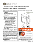
WARNING
IF THE INFORMATION IN THESE INSTRUCTIONS IS
NOT FOLLOWED EXACTLY, A FIRE OR EXPLOSION
MAY RESULT CAUSING PROPERTY DAMAGE,
PERSONAL INJURY OR LOSS OF LIFE.
—Do not store or use gasoline or other
flammable vapors and liquids in the vicinity
of this or any other appliance.
—WHAT TO DO IF YOU SMELL GAS
• Do not try to light any appliance.
• Do not touch any electrical switch; do not
use any phone in your building.
• Immediately call your gas supplier from
a neighbor’s phone. Follow the gas
supplier’s instructions.
• If you cannot reach your gas supplier,
call the fire department.
—Installation and service must be performed
by a qualified installer, service agency or
the gas supplier.
WARNING: Improper installation, adjustment,
alteration, services or maintenance can cause
injury or property damage. Refer to this manual.
For assistance or additional information
consult a qualified installer, service agency or
the gas supplier.
BVENTSPECCOVER
DUE TO HIGH TEMPERATURES, THE
APPLIANCE SHOULD BE LOCATED OUT OF
TRAFFIC AND AWAY FROM FURNITURE AND
DRAPERIES.
CHILDREN AND ADULTS SHOULD BE ALERTED
TO THE HAZARDS OF HIGH SURFACE
TEMPERATURE AND SHOULD STAY AWAY TO
AVOID BURNS OR CLOTHING IGNITION.
YOUNG CHILDREN SHOULD BE SUPERVISED
WHEN THEY ARE IN THE SAME ROOM AS THE
APPLIANCE.
CLOTHING OR OTHER FLAMMABLE MATERIAL
SHOULD NOT BE PLACED ON OR NEAR THE
APPLIANCE.
KEEP THE ROOM AREA CLEAR AND FREE
FROM COMBUSTIBLE MATERIALS, GASOLINE
AND OTHER FLAMMABLE VAPORS AND
LIQUIDS.
INSTALLER: Leave this manual with the appliance.
CONSUMER: Retain this manual for future reference.
20301938 3/13 Rev. 4
B-Vent Specialty Gas Fireplaces
TABLE OF CONTENTS
Thank you and congratulations on your purchase of a Vermont Castings Group Fireplace
Please read the Installation and Operation Instructions before using the appliance!
IMPORTANT: Read all instructions and warnings carefully before starting installation.
Failure to follow these instructions may result in a possible fire hazard and will void the warranty.
Important Safety Information.......................................3
Code Approval...............................................................4
Product Features...........................................................5
High Elevations.........................................................5
Gas Pressures..........................................................5
Gas Specifications & Orifice Size.............................5
Before You Start........................................................5
Fireplace & Framing Dimensions..............................6
Fireplace Framing.....................................................6
Clearances.....................................................................7
Venting Installation........................................................8
Installation Precautions.............................................8
Installation Planning..................................................8
Firestop Installation...................................................8
Vertical Termination...................................................9
Outside Combustion Air..........................................11
Fireplace Installation...................................................12
Check Gas Type.....................................................12
Gas Line Installation...............................................13
Electrical Wiring......................................................14
Signature Command System.....................................15
Check Gas Type.....................................................15
Electrical Wiring......................................................15
Junction Box Wiring................................................16
Command Center Wall Installation..........................16
Wall Switch Installation...........................................16
SCS Wiring Diagram...............................................17
Log Installation............................................................18
Ember Material Placement......................................18
Log Placement .......................................................18
Lava Rock and Ember Placement..........................18
Operating Instructions................................................19
What To Do If You Smell Gas..................................19
Operating Instructions.............................................20
To Turn Off Gas.......................................................20
Signature Command System
Operating Instructions.............................................21
Adjustment, Cleaning and Maintenance...................24
Venturi Adjustment..................................................24
Cleaning and Maintenance.....................................24
Safety Checklist......................................................25
Troubleshooting..........................................................26
Replacement Parts......................................................28
Firebox & Logs........................................................28
Signature Command System..................................29
Accessories.................................................................30
Warranty.......................................................................31
20301938
IMPORTANT SAFETY INFORMATION
B-Vent Specialty Gas Fireplaces
OWNER
Please leave these instructions with the appliance.
Please retain these instructions for future reference.
WARNING
INSTALLER
• Read this owner’s manual carefully and completely before trying to assemble,
operate, or service this fireplace.
• Any change to this fireplace or its controls can be dangerous.
• Improper installation or use of this fireplace can cause serious injury or death
from fire, burns, explosions, electrical shock and carbon monoxide poisoning.
This fireplace is a decorative gas appliance. This fireplace
must be properly installed by a qualified service person.
CARBON MONOXIDE POISONING: Early signs of carbon monoxide poisoning are similar to the flu with headaches, dizziness and/or nausea. If you have these signs,
the fireplace may not have been installed properly. Get
fresh air at once! Have the fireplace inspected and serviced by a qualified service person. Some people are
more affected by carbon monoxide than others. These
include pregnant women, people with heart or lung disease or anemia, those under the influence of alcohol, and
those at high altitudes.
Propane/LP gas and natural gas are both odorless. An
odor-making agent is added to each of these gases. The
odor helps you detect a gas leak. However, the odor added to these gases can fade. Gas may be present even
though no odor exists.
Make certain you read and understand all warnings. Keep
this manual for reference. It is your guide to safe and
proper operation of this fireplace.
1. This appliance is only for use with the type of gas indicated on the rating plate. This appliance is not convertible for use with other gases unless a certified kit
is used.
2. For propane/LP fireplace, do not place propane/LP
supply tank(s) inside any structure. Locate propane/
LP supply tank(s) outdoors. To prevent performance
problems, do not use propane/LP fuel tank of less
than 100 lbs. capacity.
3. If you smell gas:
• shut off gas supply
• do not try to light any appliance
• do not touch any electrical switch; do not use any
phone in your building
• immediately call your gas supplier from a neighbor’s phone. Follow the gas supplier’s instructions.
4. Never install the fireplace:
• in a recreational vehicle
• where curtains, furniture, clothing, or other flammable objects are less than 42” from the front, top
or sides of the fireplace
20301938
• in high traffic areas
• in windy or drafty areas
5. This fireplace reaches high temperatures. Keep children and adults away form hot surfaces to avoid
burns or clothing ignition. Fireplace will remain hot for
a time after shutdown. Allow surfaces to cool before
touching.
6. Young children should be carefully supervised when
they are in the same room as the appliance. Toddlers,
young children and others may be susceptible to accidental contact burns. A physical barrier is recommended if there are at risk individuals in the house.
To restrict access to a fireplace or stove, install an adjustable safety gate to keep toddlers, young children
and other at risk individuals out of the room and away
from hot surfaces.
7. Do not modify fireplace under any circumstances. Any
parts removed for servicing must be replaced prior to
operating fireplace.
8. Turn fireplace off and allow to cool before servicing,
installing or repairing. Only a qualified service person
should install, service or repair the fireplace. Have
burner system inspected annually by a qualified service person.
9. You must keep control compartments, burners and
circulating air passages clean. More frequent cleaning may be needed due to excessive lint and dust
form carpeting, bedding material, pet hair, etc. turn
off the gas valve and pilot light before cleaning fireplace.
10. Have venting system inspected annually by a qualified service person. If needed, have venting system
cleaned or repaired. Refer to Cleaning and Maintenance, Page 25.
11. Keep the area around your fireplace clear of combustible materials, gasoline and other flammable vapor
and liquids. Do not run fireplace where these are
used or stored. Do not place items such as clothing
or decorations on or around fireplace.
12. Do not use this fireplace to cook food or burn paper or
other objects.
13. Never place anything on top of fireplace.
IMPORTANT SAFETY INFORMATION
B-Vent Specialty Gas Fireplaces
CODE APPROVAL
These appliances have been tested by CSA and found
to comply with the established standards for VENTED
GAS FIREPACES in the US and Canada as follows:
LISTED VENTED GAS FIREPLACE
TESTED TO: ANSI Z21.50b-2009 / CSA2.22b-2009
IMPORTANT:
PLEASE READ THE FOLLOWING CAREFULLY
It is normal for fireplaces fabricated of steel to give off
some expansion and/or contraction noises during the
start up or cool down cycle. Similar noises are found
with your furnace heat exchanger or car engine.
IMPORTANT:
PLEASE READ THE FOLLOWING CAREFULLY
It is not unusual for gas fireplace to give off some odor
the first time it is burned. This is due to the manufacturing process.
Please ensure that your room is well ventilated during burn off - open all windows.
WARNING
It is recommended that you burn your fireplace for at
least en (10) hours the first time you use it.
WARNING
14. Do not use any solid fuels (wood, coal, paper, cardboard, etc.) in this fireplace. Use only the gas type
indicated on rating plate.
15. This appliance, when installed, must be electrically
grounded in accordance with local codes or in the
absence of local codes, with the National Electrical Code, ANSI/NFPA 70 or the Canadian Electrical
Code, CSA C22.1.
16. Do not obstruct the flow of combustion and ventilation
air in any way. Provide adequate clearances around
air openings into the combustion chamber along with
adequate accessibility clearance for servicing and
proper operation.
17. When the appliance is installed directly on carpeting,
tile or other combustible material other than wood
flooring, you must set appliance on a metal or wood
panel or hearth pad extending the full width and depth
of the appliance.
18. Do not use fireplace if any part has been exposed to
or has been under water. Immediately call a qualified service person to arrange for replacement of the
unit.
19. Do not operate fireplace if any log is broken.
20. Do not use a blower fireplace, heat exchanger fireplace or any other accessory not approved for use
with this fireplace.
21. The fireplace is not intended for use with a thermostat.
22. This appliance must be installed with draft hood in
same atmospheric pressure zone as the combustion
air inlet to the appliance.
23. For Massachusetts Residents Only: This product
must be installed by a licensed plumber or gas fitter
when installed within the Commonwealth of Massachusetts. Flexline installation must not exceed 36”.
Never connect unit to private
(non-utility) gas wells. This gas is
commonly known as wellhead gas.
Proposition 65 Warning: Fuels listed in gas,
wood burning or oil fired appliances, and the
products of combustion of such fuels, contain
chemicals known to the State of California to
cause cancer, birth defects and other reproductive harm.
California Health and Safety Code Sec. 25249.6
!
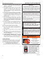
WARNING
HOT GLASS WILL
CAUSE BURNS.
DO NOT TOUCH GLASS
UNTIL COOLED.
NEVER ALLOW CHILDREN
TO TOUCH GLASS.
20301938
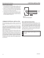
PRODUCT FEATURES
PRODUCT SPECIFICATIONS
• This appliance has been certified for use with either
•
•
•
•
natural or propane gas. See appropriate data plates.
This appliance is not for use with solid fuels.
The appliance must be installed in accordance with
local codes if any. If none exist use the current installation code, ANSI Z223.1/NFPA 54 in the US and
CSA B149 in Canada.
The appliance must be properly connected to a venting system.
The appliance is not approved for closet or recessed
installations.
HIGH ELEVATIONS
Input ratings are shown in BTU per hour and are certified without deration for elevations up to 4,500 feet
(1,370 m) above sea level.
For elevations above 4,500 feet (1,370 m) in USA, installation must be in accordance with the current ANSI
Z223.1/NFPA 54 and/or local codes having jurisdiction.
In Canada, please consult provincial and/or local authorities having jurisdiciton for installation at elevations
above 4,500 feet (1,370 m).
B-Vent Specialty Gas Fireplaces
GAS pressures
Gas Specifications & ORIFICE SIZE
Model
BVSTNSC
BVPNSC
Fuel
Nat.
Nat.
Min. Input
BTU/h
29,000
29,000
Max.Input
Orifice
BTU/h
Size
42,000
#29 (.136”)
42,000
#29 (.136”)
BEFORE YOU START
Read this homeowner manual thoroughly and follow all
instructions carefully. Inspect all contents for shipping
damage and immediately inform your dealer if any damage is found. Do not install any unit with damaged, incomplete, or substitute parts. Check your packing list to verify
that all listed parts have been received. You should have
the following:
• Fireplace (Firebox and Burner System)
• Log Set
• Volcanic Rock
• Rock Wool
• White Toggle Switch
• Switch Cover Plate
• Plastic Bag (1)
• Ziplock Bag 2” x 3” x 3”
ITEMS REQUIRED FOR INSTALLATION
• Phillips Screwdriver
• Framing Materials
• Hammer
• Wall Finishing Materials
• Saw and/or saber saw • Level
• Electric Drill and Bits
• Tee Joint
• Pliers
• Measuring Tape
• Square
• Pipe Wrench
• Caulking Material (Noncombustible)
• Fireplace Surround Material (Noncombustible)
• Piping Complying with Local Codes
• Pipe Sealant Approved for use with Propane/LPG
20301938
Natural
4.5” w.c.
7.0” w.c.
3.5” w.c.
Inlet Minimum
Inlet Maximum
Manifold Pressure
(Resistant to Sulfur Compounds)
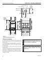
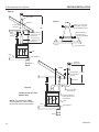
FIREPLACE & FRAMING DIMENSIONS
B-Vent Specialty Gas Fireplaces
6" B-Vent flue
4” O.A. Inlet
Gas Line Access
Rough
Opening
Depth
2356”
126M”
19”
Rough Opening
Height
756O” 426”
Gas Line Access
4256O”
3756M” 4056M” 2256M” 756O” 3556QE”
136QE”
36” 38” 1" 2256”
2456”
Figure 1 Fireplace & Framing Dimensions
1" 3856O” Rough Opening
Width - Peninsula
39” Rough Opening
Width - See-thru
FIREPLACE FRAMING
It is not necessary to install a hearth extension with this
fireplace system.
The junction box should be wired to the electrical system
at the time of installation of the fireplace. Wiring must be
performed by a qualified person in a manner to conform
with National Electrical Code ANSI/NFPA 70 and all applicable local codes.
WARNING
To install the fireplace facing flush with the finished wall,
position the framework to accommodate the thickness of
the finished wall.
CAUTION
Always check and make sure power is OFF
It is best to frame your fireplace after it is positioned and
the vent system installed. Use 2 x 4’s and frame to local1938
before attempting to install or service any
building codes.
BVST dims
electrical wiring or components.
Do not fill spaces around firebox with insulation or other materials. This could
cause a fire.
20301938
CLEARANCES
B-Vent Specialty Gas Fireplaces
CLEARANCE TO COMBUSTIBLES
Sides........................................................... 1/2”
Back............................................................ 1/2”
Top................................................................. 0”
Front............................................................. 37”
Bottom............................................................ 0”
When the fireplace is installed directly on carpeting, vinyl
tile or other combustible materials (other than wood flooring), it shall be installed on a metal or wood panel extending the full width and depth of the fireplace.
Provide adequate ventilation air.
Provide adequate accessibility clearance for servicing
and operating the fireplace.
Never obstruct the front opening of the fireplace.
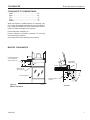
MANTEL CLEARANCES
856O” Combustible Mantel
and Trim Allowed
Above Dotted Line
12” Combustible
Material Area
256M” 9” Wall
FP2582
Measure from
Top of Opening
1"
156O”
256O”
256O”
Front of Fireplace
Side of Fireplace
Opening
FP2754
Figure 2 Mantel Clearances
FP2754
mantel clearance
20301938
45°
3"
4"
Top View
FP2582
mantel side clearance
VENTING INSTALLATION
WARNING
Read all instructions completely and thoroughly before attempting installation.
Failure to do so could result in serious injury, property damage or loss of life.
Operation of improperly installed and maintained venting system could result in
serious injury, property damage or loss of life.
NOTICE
B-Vent Specialty Gas Fireplaces
Failure to follow these instructions will
void the warranty.
• Elbow requirements allow a maximum of two (2)
90° elbows or four (4) 45° elbows per installation.
NOTE: Two (2) 45° elbows = one (1) 90° elbow
• Horizontal run must never exceed 50% of the
height of the vent system.
INSTALLATION PRECAUTIONS
Consult local building codes before beginning the installation. The installer must make sure to select the proper
vent system for installation. Before installing vent kit, the
installer must read this fireplace manual and vent kit instructions.
Only a qualified installer/service person should install
venting system. The installer must follow these safety
rules:
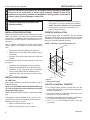
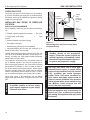
FIRESTOP INSTALLATION
A ceiling firestop must be installed if the vent passes
through a ceiling. Refer to the instructions from the pipe
manufacturer. To position firestop refer to Figures 3 and 4.
Only one (1) firestop required per frame.
NOTE: A firestop is not required at the roof.
Nails
• Wear gloves and safety glasses for protection.
• Use extreme caution when using ladders or when
on rooftops.
• Be aware of electrical wiring locations in walls and
ceilings.
The following actions will void the warranty on your venting system:
Firestop
Spacer
• Installation of any damaged venting component.
• Unauthorized modification of the venting system.
• Installation of any component part not manufac•
tured or approved by Vermont Castings Group.
Installation other than permitted by these instructions.
INSTALLATION PLANNING
“B” VENT PIPE
See venting installation instructions provided by the BVent manufacturer.
NOTE: This APPLIANCE MUST BE INSTALLED using
“B” vent type pipe that has been listed by a nationally
recognized testing agency.
Refer to B-Vent Pipe Sizing chart for proper elbow offset
runs.
This appliance must be installed using 6” type “B” vent.
Locate chimney center line dimension from a combustible back wall. Page 6, Figure 1
• Minimum vertical chimney height - 7’
• Minimum height with two (2) 90° elbows - 6’
Joist
FP2020
Figure 3 Install Firestop in Attic
Locate and Install Firestop
1. For ceiling firestops, position a plumb bob over the
center of the vertical pipe to spot a hole through which
the pipe will penetrate.
2. Drill a hole through this center point and check for obFP2020
structions (i.e. wiring or plumbing).
firestop
3. Reposition the fireplace and vent system,
if necessary,
to accommodate ceiling joists or obstructions.
10/08
4. Cut an 11” x 11” hole through the ceiling, using the
center point.
20301938
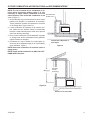
B-Vent Specialty Gas Fireplaces
Listed Vertical
Termination
Cap
Joist
Lowest Discharge
Opening
H Listed Gas Vent
12 X Roof Pitch is x/12
Nails
H (Min) - Minimum
Height from Roof to Lowest Discharge Opening
FP1022
Firestop Spacer
Figure 4 Install Firestop in Ceiling
NOTE: Vertical termination must be
at least 8’ from vertical wall.
NOTICE
5. Frame the hole with framing lumber the same size as
the ceiling joists. Position firestop. If attic is above,
mount firestop on top of framing. Figure 3. If room is
above, mount firestop on the bottom of framing. Figure
4. Secure with nails or screws.
6. Run vent through firestop.
When installing in a chase, you should insulate the chase as you would the outside walls
of your home. This is especially important in
cold climates. Insulation should be considered
a combustible material. Maintain proper clearances to all combustible materials.
NOTICE
2020
stop
08
VENTING INSTALLATION
Treatment of firestops and construction of the
chase may vary from buiding type to building
type. These instructions are not substitutes for
the requirements of local building codes. You
must follow all local building codes.
VERTICAL TERMINATION
Major building codes specify a minimum vent height
above the rooftop depending on the pitch of the roof. Refer to Figure 5 for minimum heights, provided the termination cap is at least 8’ from a vertical wall and 2’ below a
horizontal overhang. Trees, buildings, adjoining roof lines
and adverse wind conditions may require taller chimneys
than what is shown.
LOCATE AND INSTALL VERTICAL TERMINATION
NOTE: When working on the foor, cover the opening of
the installed vent pipe below to prevent debris falling in.
20301938
Figure 5 Minimum Vent Height for Various Roof Pitches
Roof Pitch
H Min. (ft)
Flat to 6/12
1’
6/12 to 7/12
1’3”
FP1022
Over 7/12
to
8/12
Typical Straight1’6”
Up Installation
Over 8/12 to 9/12
2’
1/26/00 djt
Over 9/12 to 10/12
2’6”
Over 10/12 to 11/12
3’3”
Over 11/12 to 12/12
4’
Over 12/12 to 14/12
5’
Over 14/12 to 16/12
6’
Over 16/12 to 18/12
7’
Over 18/12 to 20/12
7’6”
Over 20/12 to 21/12
8’
1. Locate and mark the vent center point on the underside
of the roof, and drive a nail trough the center joint.
2. The size of the roof hole framing dimensions depends
on the pitch of the roof.
3. Cut and frame the roof hole.
4. Continue to install vent sections through the roof hole
until reaching the appropriate distance above the
roof.
5. Attach a flashing to the roof using nails, and use a
non-hardening mastic around the edges of the flashing base when it meets the roof.
6. Attach a storm collar over the flashing joint to form a
watertight seal. Place non-hardening mastic around
the joint, between the storm collar and the vertical
pipe.
7. Attach termination per pipe manufacturer’s instructions.
VENTING INSTALLATION
B-Vent Specialty Gas Fireplaces
Figure 6
Storm Collar
Figure 7
Flashing
6” Type “B”
Gas Vent
Attach 6” “B” Vent Pipe
to Transition using Four
(4) Sheet Metal Screws
7’
Min.
Listed
Ceiling
Support
Attach Transition to
Flue Collar using
Three (3) Sheet Metal
Screws
Minimum Clearance
as Specified by Vent
Manufacturer
“B” Vent Clearance
as Specified by Vent
Manufacturer
FP2208
Wall
Units Flue Collar
&0
TRANSITIONPIPE
Floor
Gas Appliance
Approved
Termination
FP2207
4’ Max
FP2207 straight up install As Specified
6‘ Min. by Vent Manufacturer
Support
Figure 8
6” Type “B” Gas
Vent Chimney
Peninsula and See-Thru
Models Only
NOTE: This installation is NOT
recommended for colder climates.
Check local codes for allowances.
Approved Thimble for
6” Type “B” Gas vent
Through Wall
Wall
Floor
Gas Appliance
FP2209
FP2009a
vent w elbows
10
20301938
B-Vent Specialty Gas Fireplaces
OUTSIDE COMBUSTION AIR PRECAUTIONS and RECOMMENDATIONS
NOTE: The use of outside air for combustion is optional unless required by building codes. It is only
necessary to supply outside combustion air to one Duct Extended
side of fireplace. Use model 6AK combustion air kit to Miss Joist
(refer to Page 17).
1. Avoid extremely long runs and numerous turns in duct
leading from fireplace to combustion air assembly.
These conditions increase the resistance to free flow
of air through duct. Figures 9 and 10
2. Locate combustion air assembly at an exterior location. Make sure the location cannot be accidentally
blocked. Locate assembly above snow line to prevent
snow from blocking assembly.
3. Never mount combustion air inlet assembly in garage
or storage area where combustible fumes (gasoline)
might be drawn into fireplace.
4. Combustion air may be drawn from crawl space under house when adequate supply of air is provided by
open ventilation. Figure 9
Installed above Basement or
Crawl Space
FP2210a
Figure 9
NOTE: Never take combustion air from attic space or
garage space.
NOTE: Install outside combustion air ONLY ON LEFTHAND SIDE of fireplace.
8”
Maximum
FP2210a
outside air
Inlet Grille
in Soffit
(Overhang)
Figure 10
Installed on Concrete Slab
FP2210a
outside air
20301938
11
GAS LINE INSTALLATION
B-Vent Specialty Gas Fireplaces
CHECK GAS TYPE
Use proper gas type for the fireplace you are installing.
If you have conflicting gas types, do not install fireplace.
See dealer where you purchased the fireplace for proper
fireplace for your gas type.
100 gal.
(min)
Propane/
LP Supply
Tank
External
Regulator
INSTALLING GAS PIPING TO FIREPLACE
LOCATION
INSTALLATION ITEMS NEEDED
Vent
Pointing
Down
Before installing, make sure you have the items listed below:
• External regulator (supplied by installer) • Tee Joint
• Piping (check local codes)
•
Pipe
wrench
•
•
•
•
Sealant (resistant to propane/LP gas)
Test gauge connection*
Sediment trap (optional but recommended)
FP1977
Figure 11 External Regulator with Vent Pointing Down
(Propane/LP Only)
&0
EXTERNALREGULATOR
WARNING
When using copper or flex connectors use only fittings
approved for gas connections. The gas control inlet is 3/8”
NPT.
12
A qualified installer or service person
must connect appliance to gas supply.
Follow all local codes.
CAUTION
For propane/LP connections only, the installer must supply an external regulator. The external regulator will reduce incoming gas pressure. You must reduce incoming
gas pressure to between 11 and 13 inches of water. If
you do not reduce incoming gas pressure, burner system
regulator damage could occur. Install external regulator
with the vent pointing down as shown in Figure 11. Pointing the vent down protects it from freezing rain or sleet.
For propane/LP units, never connect
fireplace directly to the propane/LP
supply. This burner system requires an
external regulator (not supplied). Install
the external regulator between the burner system and propane/LP supply.
CAUTION
*A CSA design-certified equipment shutoff valve with 1/8”
NPT tap is an acceptable alternative to test gauge connection. Purchase the CSA design-certified equipment
shutoff valve from your dealer.
Use only new black iron or steel pipe.
Internally tinned copper or copper tubing
can be used per National Fuel Code, section
2.6.3, providing gas meets hydrogen
sulfide limits, and where permitted by
local codes. Gas piping system must be
sized to provide minimum inlet pressure
(listed on data plate) at the maximum flow
rate (BTU/hr). Undue pressure loss will
occur if the pipe is too small.
WARNING
Approved flexible gas line with gas connector (if allowed by local codes - not provided)
External regulators may be necessary for
natural gas. One- or two-pound systems
will damage this appliance and may cause
fire hazard.
20301938
Only persons licensed to work with gas
piping may make the necessary gas connections to this appliance.
To accommodate the various configurations, access
openings in the bottom of the unit are provided for gas
line and wall switch wires. This may not be convenient for
some installation, if so you may drill an access opening
into the lower face of the unit (1” for gas line, 1/2” for the
grommet).
NOTE: The gas line connection may be made using
1/2” rigid tubing or an approved flex connector. Since
some municipalities have additional local codes, it is
always best to consult your local authorities and the
current edition of the National Fuel Gas Code ANSI
Z223.1/NFPA 54. In Canada CSA-B149 (1 or 2) Installation Code.
A listed manual shut-off valve must be installed upstream
of the appliance. Union tee and plugged 1/8” NPT pressure tapping point should be installed upstream of the appliance. Figure 5
IMPORTANT: Install main gas valve (equipment shut-off
valve) in an accessible locations. The main gas valve is
for turning on or shutting off the gas to the fireplace.
CAUTION
B-Vent Specialty Gas Fireplaces
A manual shut-off valve must be installed
upstream of the appliance. Union tee and
plugged 1/8” NPT pressure tapping point
should be installed upstream of the appliance. Figure 12
Apply pipe joint sealant lightly to male threads. This will
prevent excess sealant form going into pipe. Excess sealant in pipe could result in clogged burner system valves.
We recommend that you install a sediment trap/drip leg
in supply line as shown in Figure 12. Locate sediment
trap/drip leg where it is within reach for cleaning. Install
in piping system between fuel supply and burner system.
Locate sediment trap/drip leg where trapped matter is not
likely to freeze. A sediment trap traps moisture and contaminants. This keeps them from going into the burner
system gas controls. If sediment trap/drip leg is not installed or is installed wrong, burner system may not run
properly.
CAUTION
WARNING
GAS LINE INSTALLATION
Use pipe joint sealant that is resistant to
liquid petroleum (LP) gas.
Check your building codes for any special requirements
for locating equipment shut-off valve to fireplaces.
Flexible Connector
Adapter Fitting
Figure 12
Shut-Off Valve
FP2205
Black Iron Pipe
&0
GASLINECONNECTION
Natural Gas
From Gas Meter
(4.5” w.c. to 7” w.c. Pressure)
Propane/LP
From External Regulator
(11” w.c. to 13” w.c. Pressure)
FP1978
20301938
13
ELECTRICAL INSTALLATION
B-Vent Specialty Gas Fireplaces
14
Electrical connections should only
be performed by a qualified, licensed
electrician. Main power must be off when
connecting to main electrical power supply
or performing service. All wiring shall be
in compliance with all local, city and state
codes. The appliance, when installed, just
be electrically grounded in accordance
with local codes, or in the absence of local
codes, with the National Electrical Code
ANSI/NFPA 70 (latest edition) and Canadian
Electrical Code, CSA C22.1.
CAUTION
WARNING
ELECTRICAL WIRING
Label all wires before disconnecting
when servicing controls. Wiring errors
can cause improper and dangerous operation.
20301938
SIGNATURE COMMAND - CHECK GAS PRESSURE and ELECTRICAL
INSTALLATION
B-Vent
Specialty Gas Fireplaces
Pressure Inlet
Pressure Outlet
Figure 13 Signature Command Valve
WARNING
1. Check gas type. The gas supply must be the same as
stated on the appliance’s rating decal. If the gas supply
is different from the fireplace, STOP! Do not install the
appliance. Contact your dealer immediately.
2. To ease installation, a 24" (610 mm) flex line with manual
shut-off valve has been provided with this appliance.
Install and attach 1/2" gas line onto shut-off valve.
3. After completing gas line connection, purge air from
gas line and test all gas joints from the gas meter to the
fireplace for leaks. Use a solution of 50/50 water and
soap solution or a gas sniffer.
4. To check gas pressures at valve, turn captured screw
counter clockwise 2 or 3 turns and then place tubing
to pressure gauge over test point. Turn unit to high.
Figure 13. After taking pressure reading, be sure and
turn captured screw clockwise firmly to reseal. Do not
over torque. Check test points for gas leaks.
Pilot Adjustment Screw
Do not FP1909a
use open flame to check for gas
leaks.
signature command valve
alternate view
8/08
Electrical Wiring
WARNING
1. This fireplace is equipped with the Signature Control
valve which operates on 6 volts. The 6 volt DC adapter
plugs into the fireplace junction box A/C power supply.
Four (4) “AA” batteries are used for back up during
power outages.
2. The Signature Command System can also be operated
without A/C power. The system can run on four (4) “AA”
batteries for approximately six (6) months under normal
use.
3. A/C power must be used to power the A/C module,
blowers, lights and AUX accessories if used with this
fireplace.
Electrical connections should only
be performed by a qualified, licensed
electrician. Main power must be off when
connecting to main electrical power supply
or performing service. All wiring shall be
in compliance with all local, city and state
codes. The appliance, when installed, must
be electrically grounded in accordance with
local codes or in the absence of local codes,
with the National Electrical Code ANSI/NFPA
70 (latest edition) and Canadian Electrical
Code, CSA C22.1.
CAUTION
General
Label all wires before disconnecting when
servicing controls. Wiring errors can cause
improper and dangerous operation.
Optional Accessory Requirements
1. This fireplace may be used with a wall switch, wall
mounted thermostat and/or Signature Command wireless controls.
2. The command center control may be mounted on the
wall with the use of the SCSWEK 15ft. wall mount extension kit.
20301938
15
ELECTRICAL INSTALLATION
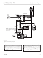
B-Vent Specialty Gas Fireplaces
JUNCTION BOX WIRING
1. This should be done before framing the fireplace. Wire
the receptacle into an electrical circuit. Wire with minimum 60° C wire in accordance with prevailing codes.
2. Remove the external junction box cover by removing
the screw from the side of the outside firebox wall.
Junction box was installed at the factory.
3. The junction box cover has a factory installed “romex”
style strain relief connector. After connecting the wires,
route the wire leads through this connector. Refer to
the wiring diagram in Figure 14.
120V AC
60Hz
Factory Supplied
Not Supplied
Junction Box
Figure 14 Junction Box Wiring Diagram
The command center may be mounted on the wall with
the use of the SCSWEK Kit (15ft. cable, junction box, wall
cover).
Mount the junction box provided at the desired location
on the wall. Do not extend beyond the 15 ft. wire cable
provided. If a longer distance is required, the 15 ft. may be
extended up to 30 ft. maximum by using two (2) SCSWEK
cables plugged together.
Route the wire from junction box to lower control area at
bottom of fireplace. Unplug the 12" cable from the command center. Attach the connector to the pins from wire
by pushing in to connector making sure to follow the color
code on connector. Plug the 15 ft. extension cable into the
2 ft. cable. Remove command center from the fireplace
and plug the other end of the extension cable into the
command center. Snap on wall cover provided and screw
to junction box.
16
FP1912
WALL SWITCH INSTALLATION
Junction box wiring
The wall switch wire connection is located off the 2 ft. wire
8/08
harness from the
control box to the command center. Fig-
ure 15. The connection is labeled “Wall Switch”. Unplug
the male and female connectors and connect the two (2)
low voltage wires provided. Run wire to desired location
on wall. Up to 50 ft. of 18 ga. wire may be used if necessary. Attach wires to wall switch. Mount the wall switch in
to junction box and screw on cover.
WARNING
COMMAND CENTER WALL INSTALLATION
Do not connect wall switch to 110 V
circuit.
20301938
ELECTRICAL INSTALLATION
B-Vent Specialty Gas Fireplaces
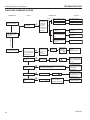
Pilot
RF Receiver
ON/OFF Button
Control Board
6V AC
Adapter
Black / Thermopile
Red / Thermopile
Sensor
Conversion
NG/LP
Spill Switch
Ignitor / Sparker
Plug-in Connector
Control Board to Command Center
OFF/LO
NOTE: Wall switch wires must be connected together if a wall switch is notPlug-in Connector
Stepper Motor to
being used.
Ground
LED
ON/HI
Master Switch
Command Center
Control Board
Optional
Wall Switch
DC Power/Green
Plug-in Connector
Control Board to
Solenoid
Gas Out
Gas In
Pilot Gas Tubing
Valve
Electrical connections should only be
performed by a qualified, licensed electrician.
Main power supply must be turned off before
connecting fans to the main electrical power
supply or performing service.
20301938
WARNING
CAUTION
figure 15 Signature Command Wiring Diagram
Electrical Grounding Instructions: This
appliance is equipped with a three-prong
(grounding) plug for your protection against
shock hazard and should be plugged directly
into a properly grounded three-prong
receptacle.
17
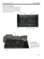
LOG PLACEMENT
B-Vent Specialty Gas Fireplaces
ROCK WOOL PLACEMENT
Break up rock wool (ember material) into dime sized pieces. Place the pieces between metal lip and burner tube.
Maintain a 3/8” space free of ember material directly in
front of the front burner ports for best performance and
effect. Blockage of the burner ports may create increased
soot and carbon build-up. Figure 16
Metal Lip
Ember Material
LG1027
Figure 16
Log #1
Metal Lip
Ember Material
LG1027
bvent designer rock wool
Valve
LOG PLACEMENT
1. Place V-notch in bottom of
Log #1 on center V section
of burner assembly. Smaller
end of log with two (2) pins
goes on same end as valve.
Figure 17
LG1028
Figure 17
18
LG1028
bv desgnr log 1
20301938
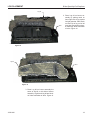
LOG PLACEMENT
B-Vent Specialty Gas Fireplaces
Log #2
Valve
2. Place Log #2 on burner assembly by placing notch on
lower right side of log against
far right grate bar. Place notch
on lower left of log on far left
grate bar. Rest log #2 on burner assembly. Note orientation
of valve. Figure 18
LG1029
Figure 18
LG1029
bv dsgnr log 2
Log #3
Valve
LG1030
Figure 19
3. Place Log #3 on burner assembly the
same as log #2 on this side of burner
assembly. Log #2 and Log #3 are identical. Note orientation of valve. Figure 19
LG1029
bv dsgnr log 3
20301938
19
LOG PLACEMENT
B-Vent Specialty Gas Fireplaces
Log #5
Log #4
Valve
Figure 20
LG1031
4. Place Log #4 by placing hole on pointed end
of log #4 onto pin on log #1. Rest notch on
bottom of log #4 onto corner of log #2. Figure 20
5. Place Log #5 by placing holes in bottom of
LG1031
log onto pin on log
#1 and pin on log #2.
Note orientation bv
of log
#5 and
dsgnr
logslocation
4 5 of
valve. Figure 20
6. Place Log #6 by placing hole in bottom of
log onto pin on log #3 with pointed side
up. Figure 21
7. Place Log #7 by placing holes in bottom
of log onto pins on log #1 and log #3 with
curved side of log towards valve. Figure
21
Log #7
Log #6
Valve
Figure 21
LG1032
20
LG1033
bv dsgnr logs 6 7
20301938
LOG INSTALLATION
B-Vent Specialty Gas Fireplaces
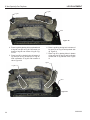
LAVA ROCK PLACEMENT
WARNING
To further enhance the hearth, lava rock may be placed
on the hearth pan area to simulate ashes. Sprinkle lava
rock on the floor of the inner combustion chamber. Evenly
distribute the rock. Do not pile the lava rock up in front of
grate. Do not place lava rock on the burner.
Do not sprinkle the lava rock or ember
chunks on top of the burner. This may
cause potential sooting, glass breakage
and a fire hazard.
CURING INSTRUCTIONS
When lit for the first time, the fireplace may emit a slight
odor for several hours. This is due to the curing and “burn
in” of external parts and lubricants used in the manufacturing process. This condition is temporary. Open doors
and windows to ventilate the room(s) sufficiently.
20301938
21
B-Vent Specialty Gas Fireplaces
OPERATING INSTRUCTIONS
WARNING
for your safety read before lighting
If you do not follow these instructions
exactly, a fire or explosion may result
causing property damage, personal injury
or loss of lie.
A. This appliance is equipped with an ignition device which automatically lights the pilot. Refer to the
instructions.
B. BEFORE OPERATING smell all around the appliance area for gas. Be sure to smell next to the floor
because some gas is heavier than air and will settle on the floor.
WHAT TO DO IF YOU SMELL GAS:
• Do not attempt to light any appliance.
• Do not touch any electric switch; do not use any phone in your building.
• Immediately call your gas supplier from a neighbor's phone. Follow the gas supplier's instructions.
• If you cannot reach your gas supplier, call the fire department.
C. Use only your finger to push in the master switch. Never use tools. If the switch will not function by
hand, do not try to repair it. Call a qualified service technician. Force or attempted repair may result
in a fire or explosion.
D. Do not use this appliance if any part of it has been under water. Immediately call a qualified service
technician to inspect the appliance and to replace any part of the control system and any gas control
that has been under water.
continued on next page
22
20301938
OPERATING INSTRUCTIONS
B-Vent Specialty Gas Fireplaces
OPERATing INSTRUCTIONS
1. STOP! Read the safety information above.
2. This appliance is equipped with an ignition device which automatically lights the burner. Do not try to
light the burner by hand.
3. Wait five (5) minutes to clear out any gas. Then smell for gas, including near the floor. If you smell gas,
STOP! Follow "B" in the safety information on page 41. If you do not smell gas, go to next step.
4. Press the master switch to the "ON" (-) position. Within eight (8) seconds it will beep once. This indicates the system is ready.
5. Press "ON " button. Sparker will spark and pilot flame will light.
6. Once pilot flame is established, the main burner flame will light automatically.
7. If the pilot will not stay lit after several tries, turn the master switch to "OFF" and call your service
technician or gas supplier.
OFF
OFF
ON
Master
Switch
ON
Command Center
FP1913
Switch box
8/08
FP1914
Pilot w sparker
8/08
TO TURN OFF GAS TO APPLIANCE
1. Turn master switch to "OFF".
2. Turn off all electrical power to the appliance if service is to be performed.
20301938
23
B-Vent Specialty Gas Fireplaces
SIGNATURE COMMAND SYSTEM OPERATION INSTRUCTIONS
FEATURES
RF Receiver
ON/OFF
Command Center
To Thermopile
To Sensor
• Easy Access Function Operation and System Con-
figuration
• Operation Confirmation/Fault Diagnostic Indications
(LED/Buzzer)
• ON/OFF/HI/Med/Low Operation
• Optional Wall Mounting
Control Board
To Sparker
NG/LP
Conversion
Control
Board
To Stepper Motor
• Electronic Ignition
• Pilot Lockout safety feature
• Electric Power Regeneration from Thermopile to save
•
•
•
•
•
•
•
battery
6-hour Automatic Shut Down Option
Convenient NG/LP Gas Type Conversion
Standing Pilot/Intermittent pilot Conversion
Previous settings Restoration Ability (Memory Off)
Uninterrupted Operation During Power Outage (Automatic Battery Backup)
ON/OFF RF Remote Receiver
Optional Transmitter Learn Capability
To Command Center
To Valve
OFF
LED
ON
Master Switch
Command
Center
Battery Door
Figure 18 Signature Command System Components
Transmitter (Optional)
Three Flame Height Settings
Low battery Indication for Transmitter Child Proof Lock-out
LCD Backlight
Security Codes 16
Countdown 6 hr Timer
TSMSC
X
X
X
X
X
X
RMSC
X
X
X
X
X
--
FP1917
Signature components
8/08
BATTERY INSTALLATION
The Command Center uses four (4) "AA" batteries as
back up for power outages. The system can operate for
approximately six (6) months on battery power.
To Install Batteries (not included):
1. Press down the battery door tabs and pull out to remove
battery door.
2. Install the batteries as indicated on Command Center.
3. Close battery door by snapping in place.
4. When the four (4) batteries are installed the system will
operate without power.
5. The batteries should be replaced when the LED indicates low battery or at least once a year.
24
20301938
SIGNATURE COMMAND SYSTEM OPERATION INSTRUCTIONS
SYSTEM CONFIGURATION/SETUP
All System configuration/setup is done on the Command
Center.
NOTE: When using On/Off wall switch, the switch must be
in the ON position to perform all configuration set ups at
the command center.
COLD CLIMATE OPTION
Choose the Mode That Best Suits Your Needs
The Signature Command System is designed to operate
in either Standing Pilot or Intermittent Pilot mode.
• The Standing Pilot Mode is best for colder climates
when the pilot must remain on continuously to prevent
condensation and ensure reliable operation.
• The Intermittent Pilot Mode is ideal for maximum effi-
ciency, igniting the pilot only when needed to start your
fireplace, lowering fuel consumption and reducing your
carbon footprint.
Either mode benefits from the instantaneous battery backup, so you never have to worry about a power outage.
NOTE: The Signature Command System comes standard in the Intermittent Pilot mode, so you must follow
the instructions below to switch to Standing Pilot Mode if
needed.
Intermittent/Standing Pilot Setup (Default intermittent)
1. Holding the ON button on the Command Center while
turning on the master switch will toggle between standing pilot and intermittent pilot.
2. After the above operation, one beep (for standing pilot) or two beeps (for intermittent pilot) will be given as
confirmation.
Six-hour Safety Shutdown Option (Default ON)
1. The system comes preset from the factory with a six
(6) hour shutdown from its last command of operation.
This is done to prevent the fireplace from continuing to
operate if unattended. You may disable this feature if
you wish.
Function
Intermittent/Standing
Pilot Setup
Standing Pilot Temp.
Shutoff
RF Remote Receiver
On/Off
Learn Remote
Transmitter
6-hour safety shutdown setup
20301938
B-Vent Specialty Gas Fireplaces
NOTE: By disabling this feature, your fireplace may continue to operate unattended.
2. When the master switch is in the ON position (“-”), pressing the ON button and the OFF button on the Command
Center simultaneously will toggle between enabling and
disabling the six-hour shutdown option.
3. After the above operation, one beep (for enabling the
six-hour shutdown option) or two beeps (for disabling
the six-hour shutdown option) will be given as confirmation.
Remote Transmitter Learn Function (Default OFF)
1. The RF receiver button located on the Control Board
must be in the on position before the learn function can
begin. Use paper clip to depress button. One beep for
RF receiver ON or two beeps for RF receiver OFF will be
given as confirmation. Refer to Figure 18 for location.
2. After the RF receiver is on, holding the OFF button on
the Command Center while turning on the master switch
will activate the learn function for the transmitter.
3. After the above operation, two beeps will be given and
the green LED on the Command Center will flash for
10 seconds.
4. During the 10 seconds, press the OFF button on a
transmitter to learn. Another two beeps will be given
to confirm a successful learning. Refer to transmitter
instructions for remote operations.
Shutting Off the Standing Pilot (Temporary Shut Off)
To shut off the standing pilot for service or summer shut
down, press and hold the ON button on the Command
Center for 3 seconds when the master switch is in the ON
position (“-”) and the main burner is off.
Note: Pilot will resume the next time system is turned
on.
Key Combinations for System Settings
NOTE: When On/Off wall switch is used, it must be in the
On position to perform all system setups.
Operation
Hold the ON ▲ button while turning on the master switch
(Beep once for standing pilot, twice for intermittent pilot)
Hold the ON ▲ button 3 seconds (when the master switch
on the main burner is off)
Push the RF receiver On/Off button on the control board
Beep once for ON and beep twice for OFF
Hold the OFF ▼ button while turning on the master switch
(Beep twice then press any handheld remote button)
Press the ON ▲ button and OFF ▼ button simultaneously
(Beep once for ON, twice for OFF)
Default Setting
Intermittent
Pilot
RF OFF
ON
25
B-Vent Specialty Gas Fireplaces
SIGNATURE COMMAND SYSTEM OPERATION INSTRUCTIONS
FUNCTIONS/OPERATION
Turning on the fireplace
1. Turn on the master switch and wait for a beep.
2. Press the ON button on the Command Center or turn
on wall switch. Pilot will light and burner will come on
High setting or last memory setting (See Turning Off
Fireplace below). For memory feature.
Pilot Safety Lockout Function
1. If the pilot doesn’t light after sparking for 30 seconds,
pilot trial lockout happens. The LED on the Command
Center flashes Green once every 2 seconds, until reset.
2. If the pilot flame is lost during normal operation, the
system will try three (3) times to relight after three (3)
failures, flame loss lockout happens. The LED on the
Command Center flashes Red-Green once every 2
seconds, until reset.
3. Turning the master switch on the Command Center to
the off position, then ON again will reset the system.
Flame Height Control
1. Press the ON button (on the Command Center) once to
turn on the main burner with maximum flame height.
2. Press the OFF button to decrease flame height. The first
two presses will decrease the flame height to medium
and low.
Function
Power Up
Fireplace ON
Fireplace OFF
Flame Height Up
Flame Height Down
3. The third press on OFF will turn off the main burner. In
standing pilot configuration, the pilot will stay; in intermittent pilot configuration, the pilot will be shut off.
Turning the Fireplace Off
There are three ways to turn the fireplace off.
1. Flip the master switch to the off (“O”) position. (This will
turn the entire system OFF.)
2. Press the OFF button to Medium, Low, then Off.
3. Hold the OFF button anytime for three seconds or by
turning off the wall switch. These two commands of
OFF are (Memory Off) the system will remember all last
settings before turning off. The next time the fireplace is
turned on, all settings will resume. To reset, change to
the desired settings and shut off by using the Memory
Off commands and the system will be reset to those
new settings.
Command Center Operations:
The following functions are available on the Command
Center.
Operation
Flip the master switch to the ON ("_") position to power up the system
Press the ON ▲ button on the Command Center or turn on wall switch to turn the fireplace on
Flip the master switch to the OFF ("o") position OR press the OFF ▼ button 3 times OR for Memory Off, hold the OFF ▼ button 3 seconds, or turn off wall switch
Press the ON ▲ button once to turn on the fireplace with maximum flame height
Press the OFF ▼ button to lower the flame height to Medium and Low
Self Diagnostics Chart:
The Command Center has a self-diagnostic LED enabling
you to troubleshoot problems and potentially avoid a
service call. Please refer to the charts below for indicator
reference.
26
Fault
Conversion Cover Missing
Spark Fail
No Sensor Signal
Pilot Lockout - trial
Pilot Lockout - flame loss
Low Battery
No or Low Thermopile Power
Learning
AC Power On
Pressure Switch Failed (Power Vent only)
LED Indication
One RED (1 time)
Two RED (1 time)
Three RED (1 time)
One GREEN, every 2 sec. (until manual reset)
One RED-GREEN, every 2 sec. (until manual reset)
One RED, every 10s (continuously)
Two RED, every 10s (continuously)
GREEN Flashes, every 1 sec. (for 10 sec.)
GREEN solid
One RED every 2 sec. (until manual reset)
20301938
ADJUSTMENT, CLEANING and MAINTENANCE
B-Vent Specialty Gas Fireplaces
Venturi Adjustment
Natural gas models have a closed shutter. Opening the air
shutter will cause a more blue flame, but can cause flame
lifting from the burner ports. Propane gas models have an
air shutter set at 3/16” (.188 mm) open. The same conditions as above apply for propane gas.
Figure 19
WARNING
NOTE
FP2217
Air shutter adjustment must only be
done by a qualified gas installer.
Turn off gas before servicing fireplace. It
is recommended that a qualified service
technician perform these check-ups at
the beginning of each heating season.
Air flowing through the appliance will cause dust and lint
to collect on the grate, burner and logs. Excessive buildup of dust and lint can cause the pilot and burner to operate improperly and produce hazardous levels of carbon
monoxide, a poisonous gas. The appliance may produce
carbon (soot) during operation. This carbon (soot) may
collect on some logs, some areas of the grate and on the
fireplace and vent. Slight carbon build-up is acceptable.
The following is a recommended monthly maintenance
program:
1. Turn the gas OFF at the line shut-off valve and allow
the appliance to cool.
2. Blow or vacuum all dust and lint out of the appliance,
paying particular attention to the pilot, air shutter end
of the burner, air passage into and through the appliance and control.
20301938
Closed for Natural Gas
3/16” Open for Propane/LP Gas
&0
AIRSHUTTER
3. Vacuum or brush away all dust, carbon or lint on the
logs and grate.
4. Turn the gas ON at the line shut-off valve and light the
appliance according to the lighting instructions.
5. Check all piping, pilot tubing and manifold connections
for leaks with a soap and water or liquid leak detecting
solution. If any leaks are observed, turn the gas OFF
immediately and make the necessary repairs.
6. Light the pilot and visually inspect the flame appearance. NOTE: Any maintenance of the appliance that
requires disconnection of the appliance from the gas
line or removal of the control, burner or pilot should
only be performed by a qualified person.
27
B-Vent Specialty Gas Fireplaces
Correct installation and safe operation of this appliance
require, but are not limited to the following:
DO’S
1. Do use this appliance only on type of gas it is designed, certified and equipped.
2. Do install this appliance and all gas piping according
to local codes, or in the absence of local codes, according to the current National Fuel Gas Code, ANSI
Z223.1 latest edition.
3. Do disconnect or isolate the appliance during supply
line pressure testing.
4. Do locate the appliance out of traffic patterns as much
as possible.
5. Do keep in mind that some furniture materials such as
vinyl or plastic may deform at the temperatures near
this appliance and must be kept at greater distances.
6. Do use joint compound (pipe dope) on threaded joints
of gas piping that is resistant to the action of liquefied
petroleum gas.
7. Do include a manual shutoff valve and union ahead
of the controls so the controls and appliance may be
removed for servicing if necessary.
8. Do use only ground joint unions in gas piping.
9. Do include a drip leg in the gas supply connection to
the appliance.
10. Do use only soap-water solution or liquid gas leak solution when checking for leaks in the gas plumbing.
Never use matches, candles or other ignition sources
when checking for leaks.
11. Do connect the appliance only to an agency listed
vent system.
12. Do adjust the air shutter as required to produce the
proper flame as described in this manual.
13. Do keep the area around the appliance clear and free
from combustible materials, gasoline and other flammable vapors and liquids.
14. Do follow the lighting and operation procedures given
in this manual.
15. Do periodically inspect the pilot and burner flame as
described in the maintenance section of this manual.
16. Do clean the appliance as specified in the maintenance section of this manual.
17. Do provide electrical grounding of appliance in accordance with local codes and/or the National Electric
Code ANSI NFPA 70 latest edition.
18. Do inspect the entire venting system at least once a
year and replace all parts that show evidence of damage or deterioration.
28
SAFETY CHECKLIST
DONT’S
1. Don’t modify or alter the appliance cabinet (jacket) in
any way.
2. Don’t use this appliance on any gas other than the
type for which it is equipped. The type of gas for which
the appliance was equipped at the factory is stamped
on the rating plate located on the bottom of the appliance.
3. Don’t install the appliance in areas where gasoline
or any flammable liquefied or any explosive materials
may be used or stored.
4. Don’t obstruct the flow of air for combustion and ventilation into or away form the appliance at any time.
5. Don’t use this appliance if any part has been under
water. Immediately call a qualified service technician
to inspect the appliance and to replace any part of the
control system and any gas control which has been
under water.
6. Don’t operate this appliance without proper electrical
grounding according to local codes or the National
Electric Code ANSI NFPA 70 latest edition.
7. Don’t operate this appliance without a proper vent.
8. Don’t connect this appliance to a chimney flue serving a solid fuel burning appliance.
9. Don’t use thermostat or automatic burner cycling devices.
20301938
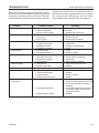
TROUBLESHOOTING
B-Vent Specialty Gas Fireplaces
While Vermont Castings Group has made every reasonable effort to ensure this appliance operates properly and
satisfactorily, sometimes problems do arise. The following troubleshooting chart lists several problems with their
Problem
probable cause and remedy. Any adjustments and/or replacements must be by a qualified person. Do not replace
any component with a different type. Use only components supplied by the manufacturer for this appliance.
Probable Cause
Remedy
Flame too large
1. Pressure regulator set too high
2. Defective regulator
3. Burner orifice too large
1. Reset, using manometer
2. Replace
3. Replace with correct size
Noisy flame
1. Too much primary air
2. Noisy pilot
3. Burr in orifice
1. Adjust air shutters
2. Reduce pilot gas
3. Remove burr or replace
Yellow or excessive flame
1. Too little primary air
2. Clogged burner ports
3. Misaligned orifices
4. Clogged vent system
1. Adjust air shutter
2. Clean ports
3. Realign or replace burner
4. Clean
Floating flame
1. Blocked venting
2. Insufficient primary air
1. Clean
2. Adjust air shutter
Delayed ignition
1. Improper pilot location
2. Pilot flame too small
3. Burner ports clogged
4. Low pressure
1. Reposition pilot
2. Check orifice, increase gas
3. Clean ports
4. Adjust pressure regulator
Failure to ignite
1. Main gas off
2. Defect in gas valve
1. Open manual shut-off valve
2. Replace
1. Defective auto valve
1. Clean or replace
1. Defective auto valve
2. Defective pilot sensor
3. Defective switch
4. Defective auto pilot valve
1. Replace
2. Replace
3. Repair or replace
4. Replace
Burner won’t turn off
Burner won’t turn on
Burner & pilot 1. Poorly functioning vent system
1. If pilot can be relit but main burner flame go out & pilot go off after ignition, have vent system checked and corrected im-
mediately
2. Gas supply interrupted
2. Try relighting pilot and main burner. If pilot won’t relight, check thermo-
couple and control
3. Defective pilot or control
3. Replace
20301938
29
TROUBLESHOOTING
B-Vent Specialty Gas Fireplaces
SIGNATURE COMMAND SYSTEM
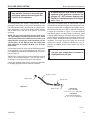
OPERATION Install batteries and/or plug in the AC board FAULT No beep in about 8 seconds A Using battery? Make sure Command Center and the control board are connected by a 2 feet or 15 feet cable After the beep Flip the master switch (rocker switch) to the ON position Press the ON button on the Command Center No beep or no sound from the valve indicating pilot solenoid open B No sparking on the pilot C Sparking doesn’t continue D Pilot doesn’t light Main burner doesn’t light ACTION DIAGNOSIS E F Check NG/LP conversion cap and control board connections Check pilot connections Battery polarity wrong? Re-install batteries Battery voltage low? Change batteries AC plug is plugged to AC mains? Plug the AC plug to AC mains The 5-pin connector on the AC board broken or bent? Repair or replace the AC Board LED on the Command Center does not show solid green? Replace the AC Board Check valve connections Check grounding Check power supply (go through ) A Replace the Control Board or Command Center Go through B Sparking is happening elsewhere (under the pilot), re-install/replace the pilot The Control Board is having interference from the surrounding metal (Ground) Check gas supply Go through E Go through C The sensor on the pilot is not in the flame (pilot flame too small)? Re-install the Control Board, move it around or change the Control Board Sparking is not in the path of gas flow, adjust sparker position or replace the pilot Adjust sensor position or replace the pilot FP1911 troubleshoot sc 8/08 30
20301938
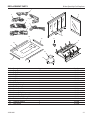
REPLACEMENT PARTS
B-Vent Specialty Gas Fireplaces
1
9
7
2
3
4
6
5
12
8
13
17
11
14
* * *
10
*
*
*
*
*
16
* * * * *
*
*
*
*
15
13
14
Ref. 1.
2.
3.
4.
5.
6.
7.
8.
9.
10.
11.
12.
13.
14.
15.
16.
17.
Description
Twig, Top
Twig, End
Twig, Front Y
Log, Back
Log, Front
Log, Middle
Front Door Assy
Handle Package
End Door Assy
Hearth Pan Ptd.
Burner Assy
Access Panel Ptd.
Hearth Pan Edge Short Ptd.
Hearth Pan Edge Long Ptd.
Radiation Shield Assy
Transition Section
Limit Switch
20301938
Qty.
1
1
1
1938
1
BVST BVP parts
1
1
2
1
2
1
1
1
2
2
1
1
1
Part No.
074270
074269
074268
074266
074265
074267
20304161
037438
20304162
071584
079057
071585
071567
071568
070945
070989
071589
31
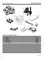
REPLACEMENT PARTS
B-Vent Specialty Gas Fireplaces
1
2
4
5
3
6
7
10
11,12
14
SIGNATURE COMMAND SYSTEM
Ref.
1.
2.
3.
4.
5.
6.
7.
8.
9.
10.
11.
12.
13.
14.
32
Description
Qty.
Gas Valve Assy
1
Pilot Assy
1
Control Box
1
Command Center
1
Burner Tube
1
Flexline w/ Shut-off
1
Injector
1
Wire Valve Control (not shown)
1
Wire Command Ctr. Control Box 2’ (not
shown)
1
1938
A/C Adapter (6 volt)
BVST BVP SC 1
parts
Accessories
Hand Held Remote Control w/ HI/LO & Timer
Touch Screen Remote Hi/Lo and Timer
SCS Wall Mount Extension Kit (15’ wire, rough-in box, wall cover) (not shown)
SCS AC Module (Optional blower, Light & Aux. Control)
Part No.
80D0001
80D0006
80D0018
80D0005
27D0435
69D0030
27D0433
80D0010
80D0008
80D0041
RMSC
TSMSC
SCSWEK
SCSACM
20301938
ACCESSORIES
ACCESSORIES
Outside Air Kit
Back Refractory Look Panel
Side Refractory Look Panel
CONVERSION KIT
6CSC LP Conversion Kit
20301938
B-Vent Specialty Gas Fireplaces
6AK
DBVFBB
DBVFBS
BVCKPS
33
B-Vent Specialty Gas Fireplaces
34
20301938
B-Vent Specialty Gas Fireplaces
LIMITED LIFETIME WARRANTY POLICY
LIFETIME WARRANTY
The following components are warranted for life to the original owner, subject to proof of purchase;
Firebox, Combustion Chamber, Heat Exchanger, Grate and Stainless Steel Burners.
FIVE YEAR WARRANTY
The following components are warranted for five (5) years to the original owner, subject to proof of
purchase; Ceramic Fiber Logs.
BASIC WARRANTY
Vermont Castings Group warrants the components and materials in your gas appliance to be free from
manufacturing and material defects for a period of two (2) years from date of installation. After installation, if any of the components manufactured by Vermont Castings Group in the appliance are found to
be defective in materials or workmanship, Vermont Castings Group will, at its option, replace or repair
the defective components at no charge to the original owner. Vermont Castings Group will also pay for
reasonable labor costs incurred in replacing or repairing such components for a period of two (2) years
from date of installation. Any products presented for warranty repair must be accompanied by a dated
proof of purchase.
This Limited Lifetime Warranty will be void if the appliance is not installed by a qualified installer in
accordance with the installation instructions. The Limited Lifetime Warranty will also be void if the appliance is not operated and maintained according to the operating instructions supplied with the appliance, and does not extend to (1) firebox/burner assembly damage by accident, neglect, misuse, abuse,
alterations, negligence of others, including the installation thereof by unqualified installers, (2) the cost
of removal, reinstallation or transportation of defective parts on the appliance, or (3) incidental or consequential damage. All service work must be performed by an authorized service representative.
This warranty is expressly in lieu of other warranties, express or implied, including the warranty of
merchantability of fitness for purpose and of all other obligations or liabilities. Vermont Castings Group
does not assume for it any other obligations or liabilities in connection with sale or use of the appliance.
In states that do not allow limitations on how long an implied warranty lasts, or do not allow exclusion
of indirect damage, those limitations of exclusions may not apply to you. You may also have additional
rights not covered in the Limited Lifetime Warranty.
Vermont Castings Group reserves the right to investigate any and all claims against the Limited Lifetime
Warranty and decide upon method of settlement.
IF WARRANTY SERVICE IS NEEDED...
1. Contact your supplier. Make sure you have your warranty, your sales receipt and the model/serial
number of your Vermont Castings Group product.
2. DO NOT ATTEMPT TO DO ANY SERVICE WORK YOURSELF.
20301938
35
Vermont Castings Group
149 Cleveland Drive • Paris, Kentucky 40361
www.vermontcastingsgroup.com