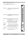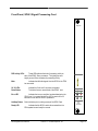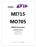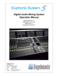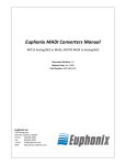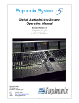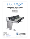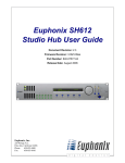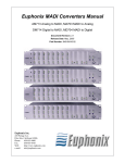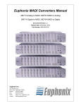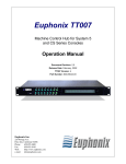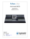
1
Euphonix
Euphonix
AES Sync
AES Sync
In
Euphonix
Euphonix
Euphonix
Euphonix
Euphonix
Euphonix
Euphonix
Euphonix
Euphonix
Euphonix
Euphonix
In
Out
Euphonix
MADI Inputs
MADI Inputs
A
A
B
B
C
C
Out
Word Sync
In
Word Sync
75
Out
In
75
Out
FireWire
D
Chassis ID
Sync Source
Sync Source
Int
AES
WC
Int
44.1
96
44.1
48
96
DSP Activity
DSP Activity
A
48
PD Custom
Select
Locked
PU
PD Custom
Select
Active
3V
Reset
Error
HotSwap
Ready
FC-631
FRAME
CONTROLLER
A
A
B
B
C
DSP Activity
A
DSP Activity
A
DSP Activity
A
DSP Activity
A
DSP Activity
A
DSP Activity
A
DSP Activity
C
A
DSP Activity
A
D
A
D
MADI Input OK
MADI Input OK
B
B
B
B
B
B
B
B
B
B
C
C
C
C
C
C
C
C
C
C
D
D
D
D
D
D
D
D
D
D
B
B
E
E
E
E
E
E
E
E
E
E
C
C
F
F
F
F
F
F
F
F
F
F
D
D
A
A
Locked
Active
5V
MADI Outputs
Chassis ID
AES Word
PU
D
MADI Outputs
FireWire
Mute
5V
3V
Mute
5V
3V
Mute
5V
3V
Mute
5V
3V
Mute
5V
3V
Mute
5V
3V
Mute
5V
3V
Mute
5V
3V
Mute
5V
3V
Mute
5V
3V
Mute
5V
3V
Mute
5V
3V
5V
3V
Reset
Error
Reset
Error
Reset
Error
Reset
Error
Reset
Error
Reset
Error
Reset
Error
Reset
Error
Reset
Error
Reset
Error
Reset
Error
Reset
Error
Reset
Error
HotSwap
Ready
HotSwap
Ready
HotSwap
Ready
HotSwap
Ready
HotSwap
Ready
HotSwap
Ready
HotSwap
Ready
HotSwap
Ready
HotSwap
Ready
HotSwap
Ready
HotSwap
Ready
HotSwap
Ready
HotSwap
Ready
FC-631
FRAME
CONTROLLER
SP-661
SIGNAL
PROCESSOR
SP-661
SIGNAL
PROCESSOR
SP-661
SIGNAL
PROCESSOR
SP-661
SIGNAL
PROCESSOR
SP-661
SIGNAL
PROCESSOR
SP-661
SIGNAL
PROCESSOR
SP-661
SIGNAL
PROCESSOR
SP-661
SIGNAL
PROCESSOR
SP-661
SIGNAL
PROCESSOR
SP-661
SIGNAL
PROCESSOR
MM-641
MADI
INTERFACE
MM-641
MADI
INTERFACE
DF64 Digital Frame Manual
Version 1.0
Part# 840-07523-01
Publish date: October 1999
Revision B
Euphonix Inc. 220 Portage Avenue Palo Alto , CA 94306
Tel: (650)855-0400 Fax: (650) 855-0410 Web Page: www.euphonix.com
In the interest of continued product development, Euphonix reserves the right to make improvements in this manual and the product it
describes at any time, without notice or obligation.
System 5, SYSTEM 5, PatchNet, eMix, EuCon, R-1, Studio Hub, Digital Studio Controller, DSC, CleaR, GainBall, SnapShot,
SnapShot Automation, SnapShot Recall and Total Automation are trademarks of Euphonix Inc.
This page intentionally left blank
DF64 Digital Frame Manual
Version 1.0 ©1999 Euphonix, Inc.
Page 2
TABLE OF CONTENTS
Box Inventory..............................................................................................................4
Safety and Precautions ..............................................................................................4
Power On Sequence...................................................................................................5
CE/TUV/UL/CSA ..........................................................................................................5
Component Overview.................................................................................................6
Functional Description ........................................................................................................................6
Applications..........................................................................................................................................6
Hardware Operation ...................................................................................................8
Dimensions and Weight ......................................................................................................................8
Front Panel, FC631 Frame Controller ................................................................................................9
Front Panel, MM641 MADI Interface Card........................................................................................11
Front Panel, SP661 Signal Processing Card ...................................................................................12
Technical Specifications..........................................................................................13
Performance Specifications..............................................................................................................13
Environmental Requirements ...........................................................................................................14
Power Requirements .........................................................................................................................14
Serviceability ......................................................................................................................................14
User Reference ............................................................... Error! Bookmark not defined.
DF64 Hookup Diagram............................................................................ Error! Bookmark not defined.
DF64 Digital Frame Manual
Version 1.0 ©1999 Euphonix, Inc.
Page 3
Box Inventory
The DF64 Digital Frame box contains the following items.
Description
Part #
946-06938-01
DF64 Digital Audio Frame
600-06829-00
Power supply, DF64
946-06940
Dummy power supply
936-06541-01
Rackmount Hardware
032-03613-00
Power Cord, IEC/US, 8’
726-06526-01
Front Panel Blank, Modular
946-07106-01
Card, FC631 Frame Controller
936-07226-01
FC631 Pack
946-07105-01
Card, MM641 MADI Interface
936-07227-01
MM641 Pack
946-07113-01
Card, SP661 Signal Processor
DF64 Manual
Qty
1
1
2
1
*
1
1
2
2
*
1
* - Number varies depending on configuration ordered.
Safety and Precautions
1) Read Instructions - Read all the safety and operation instructions before operating the
DF64 Digital Frame.
2) Heed Warnings – Follow all warnings on the DF64 and in these operating instructions.
3) Water and Moisture – Do not use the DF64 near water.
4) Heat – Locate the DF64 away from heat sources.
5) Power Sources – Connect the Am713/MA703 only to a power supply of the type
described in these operation instructions or as marked on the DF64.
6) Power Cord Protection – Route power cords so that they are not likely to be walked
upon or pinched by items placed on them.
7) Object and Liquid Entry – Do not drop objects or spill liquids on the DF64.
8) Damage Requiring Service – The DF64 should be serviced only by qualified personnel
when:
a) Objects have fallen, or liquid has spilled into the DF64; or
b) The DF64 does not appear to operate or exhibits a marked change in
performance; or,
c) The DF64 have been dropped or there is damage to a chassis.
9)
DF64 Digital Frame Manual
Servicing – Do not attempt to service the DF64 beyond those means described in this
operation manual. All other servicing should be referred to the Euphonix Tech Support
department.
Version 1.0 ©1999 Euphonix, Inc.
Page 4
10) Fuse replacement – To prevent electric shock and avoid risk of fire, replace fuse only
with the same type and rating.
11) To prevent electric shock, do not use the DF64 polarized plug with and extension cord,
receptacle or other outlet unless the blades can be fully inserted to prevent blade
exposure.
12) Grounding or Polarization – Do not defeat the grounding or polarization of the DF64.
13) Cooling - Ventilation for cooling is provided to the DF64 via four rear panel mounted
fans. These fans draw cooling air through the chassis from the openings on the front
panel. To avoid damage to the unit, do not block the fans or the front panel openings.
Do not disconnect the fans.
THERE ARE NO USER SERVICEABLE PARTS IN THE DF64. However, individual cards
can be swapped by the user.
Power On Sequence
It is recommended that the DF64 Digital Frame(s) are powered on after all the other System
5 components have been powered on and the Virtual Mixer has been loaded in all the
corresponding Digital Pilot computers.
CE/TUV/UL/CSA
The DF64 is fully CE compliant. Documentation is available from the factory.
DF64 Digital Frame Manual
Version 1.0 ©1999 Euphonix, Inc.
Page 5
Component Overview
Functional Description
The DF64 Digital Frame is the Digital Signal Processing Center of System 5. Digital Audio is
routed to and from the DF64 in MADI. Control of the DF64 is provided by a Digital Pilot
Computer (one per DF64,) which in turn communicates with the System 5 Control Surface. Thus
the DF64 is under control of the System 5 system operator.
The DF64 assembly is a standard 19” rack width and 9RU high.
Applications
In its role of Digital Signal Processing Center for System 5 , the DF64 performs three
functions;
• Signal I/O
• Signal Routing and Synchronization
• Signal Processing
There are 3 different types of cards in the DF64 that address each of the above functions.
The number and type of cards in the DF64 are configurable. There are one to four DF64
frames per System 5 , each of which can contain up to 14 cards. One SC253d Digital Pilot is
required for each DF64.
Signal I/O– MM641 MADI Interface Card
All audio I/O is handled by the MM641 MADI Interface Card. MADI signals input at 24 bit
fixed point resolution are converted to 32 bit floating point resolution for distribution over the
backplane to other cards (the SP-661 Signal Processor Cards use 40 bit floating point
processing internally—see below). Each MM641 card can input 224channels and output 224
channels of audio (56 channels per MADI port.) The MADI cards can also support 64 channel
MADI if an application requires this. When operating at 96kHz sample rates, each MADI port
handles 28 audio channels.
Signal Routing and Synchronization – FC631 Frame Controller Card
All patching between I/O, Channels, and Busses is done on the Time Division
Multiplexed(TDM_ bus and controlled by the FC631 Frame Controller Card. The FC631 Card
also provides a FireWire interface to the SC253d Pilot Computer. The DF64 includes a slot for a
backup FC631 card, for applications where maximum fault tolerance is required.
The DF64 typically acts as a Sample Rate Slave in System 5 synchronization, although it can
be a Master if desired. The Sync Source section on the FC631 front panel allows the user to
select between AES or Word Sync (slave mode) or Internal Sync (master mode). Once locked to
the selected sync source, the FC631 distributes a sync clock to the other cards in the DF64
frame and outputs a reference clock on its AES and Word sync output connectors. The master
Sample Rate clock signal for the DF64 and all System 5 system components comes from the
Studio Hub (SH612), which in turn can be used to synchronize other digital components in the
studio.
DF64 Digital Frame Manual
Version 1.0 ©1999 Euphonix, Inc.
Page 6
Signal Processing – SP661 Signal Processor Card
The SP661 Signal Processor card performs all signal processing functions in the DF64. This
card comprises six Analog Devices SHARC processors, massive DMA facilities for transferring
audio data, and a RISC CPU for management of card functions. The programmable DSP
architecture on the SP661 card allows it to perform channel processing, mixing, or various other
signal processing tasks.
DF64 Digital Frame Manual
Version 1.0 ©1999 Euphonix, Inc.
Page 7
Hardware Operation
Dimensions and Weight
Height: 15.75 inches
Width: 19 inches
Depth: 17.3 inches
Weight: 72lbs (approx) with 9-SP661, 1-FC631, 2-MM641 cards, and 1-power supply. Weight
can vary with configuration.
19”
17”
16”
17.3”
15.75”
Front
17”
Side
17”
5
Rear
DF64 Digital Frame Manual
Version 1.0 ©1999 Euphonix, Inc.
Page 8
Front Panel, FC631 Frame Controller
AES Sync In
(3-pin Lemo Female) AES/EBU formatted sync input. The
DF64 clocks to the signal at this port when Sync Source is set to
AES. An XLR female to LEMO adapter cable is provided.
AES Sync Out
(3-pin Lemo Male) AES/EBU formatted sync output. This
signal is active regardless of the selected sync source. A LEMO
to XLR male adapter cable is provided.
Euphonix
Word In
Word Out
(BNC) TTL-level square wave Sync Input. DF64 Sample
rate is clocked to the signal at this port when Sync Source is set
to Word.
AES Sync
In
Out
Word Sync
(BNC) TTL-level square wave sync output. This signal is
active regardless of selected sync source.
In
IEEE 1394 ports (2)
(IEEE 1394) High speed communication interface to the
SC253d Pilot Computer. This interface carries real-time control
and metering data between the SC253d and the DF64. The
cable from the SC253d can be plugged into either of the two
ports.
Chassis ID Display
Sync Source LEDs
Sample Rate LEDs
Each DF64 chassis must be assigned a unique ID which
identifies it among multiple frames in a system. The ID is set
using a rotary switch located on the Backplane PCB. The
System is shipped with the ID switch preset to the proper
number, so users will not normally need to access the switch.
The switch position must match that of the corresponding Digital
Pilot computer.
The top three LEDs in the Sync Source section indicate
the selected sync source: AES, Word, or Internal. The sync
source is changed by pressing the select button (a paper clip or
similar tool is required) Refer to the System 5 Operation Manual
for information on changing the sync source.
The bottom six LEDs in the Sync Source section indicate
the sample rate that is measured by the FC-631 card. Standard
sample rates include 44.1kHz, 48kHz, 96kHz, and the 0.1% “pullup” and “pull-down” rates associated with each of these standard
rates. If the FC631 is locked to a non-standard sample rate, the
CUSTOM LED will be lit.
Select Button
Use this button to manually select the Sync source (and
Sample Rate, if Internal Sync is selected) Refer to the System 5
Operation Manual for information on changing the sync source.
Locked LED
Indicates that the FC631card is receiving and locked to
the selected sync source. This LED must be lit to ensure
proper audio operation of the DF64. .
Active LED
When lit, Indicates that the FC631 is actively controlling
the TDM bus. In a system with two FC631 cards, this LED is
DF64 Digital Frame Manual
Version 1.0 ©1999 Euphonix, Inc.
75
Out
FireWire
Chassis ID
Sync Source
AES Word
Int
44.1
96
48
PU
PD Custom
Select
Locked
Active
5V
3V
Reset
Error
HotSwap
Ready
FC-631
FRAME
CONTROLLER
Page 9
used to determine which card is Active and which is on stand-by.
5V, 3V LEDs
Indicate that 5 volt and 3 volt power are present.
Reset Button
This button forces a manual reset of the FC631 card.
Error LED
Indicates that an error condition has been detected on the
FC631. It is normal for this LED to remain lit for 30 seconds or
more after the DF64 is powered on.
HotSwap Button
Push this button prior to making a swap of the FC631
Card. In a system fitted with two FC-631 cards, the backup card
will take over when the HotSwap button is pressed on the active
card (supported in v2.0).
Ready LED
Indicates that FC631 is disconnected from the DF64
system bus and ready for removal.
DF64 Digital Frame Manual
Version 1.0 ©1999 Euphonix, Inc.
Page 10
Front Panel, MM641 MADI Interface Card
Euphonix
MADI Inputs
MADI In Ports(4)
(BNC) Digital audio signal input. Each port can receive 56
or 64 channels of audio at sample rates up to 48kHz, or 28 or 31
channels at 96kHz.
A
B
C
MADI Out Ports(4)
(BNC) Digital audio signal output. Each port can transmit
56 or 64 channels of audio at Sample Rates up to 48kHz, or 28
or 31 channels at 96kHz.
D
MADI Outputs
A
B
MADI Input OK LEDs
Indicate that a MADI signal is present at the respective
input port(s). A flashing LED indicates a protocol or sync error
on the incoming MADI line.
Mute
Indicates that all channels of audio from the MM641 to the
TDM bus are muted. MADI output channels are muted
automatically if the hardware detects a corrupted signal.
C
D
MADI Input OK
A
B
5V, 3V LEDs
Indicate that 5 volt and 3 volt power are present.
Reset Button
This button forces a manual reset of the MM641 card.
Error LED
HotSwap Button
Ready LED
Indicates that an error condition has been detected on the
MM641 card. It is normal for the Error LED to be lit for 30
seconds or more after the DF64 has been powered on.
card.
Push this button prior to making a swap of the MM641
Indicates that the MM641 card is disconnected from the
DF64 system bus and ready for removal.
DF64 Digital Frame Manual
Version 1.0 ©1999 Euphonix, Inc.
C
D
Mute
5V
3V
Reset
Error
HotSwap
Ready
MM-641
MADI
INTERFACE
Page 11
Front Panel, SP661 Signal Processing Card
Euphonix
DSP Activity LEDs
These LEDs indicate the level of processing activity on
each of the SP661 Sharc processors. The lights glow more
brightly as each Sharc increases its processing activity.
DSP Activity
A
B
Mute
Indicates that all Audio signals from the SP661 to the TDM
bus are muted.
C
D
E
F
5V, 3V LEDs
Indicate that 5 volt and 3 volt power are present.
Reset Button
This button forces a manual reset of the SP661 card.
Mute
Error LED
Indicates that an error condition has been detected on the
SP661 card. Is is normal for the Error LED to remain lit for 30
seconds or more after the DF64 is powered on
HotSwap Button Push this button prior to making a swap of the SP661 Card.
Ready LED
Indicates that the SP661 card is disconnected from the
DF64 system bus and ready for removal.
DF64 Digital Frame Manual
Version 1.0 ©1999 Euphonix, Inc.
5V
3V
Reset
Error
HotSwap
Ready
SP-661
SIGNAL
PROCESSOR
Page 12
Technical Specifications
Performance Specifications
Sync sources:
Word Sync In
AES Sync In
Internal Fs:
Sample Rate Range (Fs)
Locking to External Source:
Sync Outputs:
Word Clock Out
AES Sync Out
Word Sync, AES
1 BNC
1 Lemo 3-pin (adapter to XLR female provided)
44.1, 48, 96 kHz +/-20ppm
40,000Hz → 48,480Hz (in single speed mode)
80,000Hz 96,960Hz (in double speed mode)
AES and Word Sync
1 BNC
1 Lemo 3-pin (adapter to XLR male available)
MADI
MADI input:
MADI output:
4 (BNC) 75ohms, 56 channel (with nominal Sample Rates ≥40kHz and
≤48.48kHz) Full 24-bit precision.
“MADI Input OK” LED per input port
4 (BNC) 75ohms, 56 channel (with nominal Sample Rates ≥40kHz and
≤48.48kHz) Full 24-bit precision.
Backplane
684-channel pipelined TDM bus (32-bit floating point audio data)
342 channels at 80kHz -> 96.96kHz operation
32-bit floating-point audio data format (converted to/from 24-bit
24-bit fixed point on MM641 Card)
DSP
40-bit floating-point internal computation
32-bit floating point maintained throughout all internal paths
7.5 GFLOPS Peak DSP horsepower per DF64 Frame
(using 9 SP661 Cards and 2 MM641 Cards)
29.8 GFLOPS Peak DSP horsepower per system
(4 DF64 frames)
Total Harmonic Distortion
0.005% or better, 20Hz ~ 20kHz, -18dBFS (through any audio path)
Audio Throughput Delay
44 Samples Typical (MADI In -> Channel -> Mix Bus -> Monitor Bus ->
MADI Out )
(0.92 msec @ Fs=48kHz, 0.46 msec @ Fs=96kHz
Delay remains constant with EQ/Filters/Dynamics In or Out
Additional user-adjustable delay per channel (up to 240 samples)
FireWire (IEEE1394)
2 ports on FC631 front panel.
Used for real-time system control and configuration
200Mbps max data rate
DF64 Digital Frame Manual
Version 1.0 ©1999 Euphonix, Inc.
Page 13
Environmental Requirements
Operating Temperature:
0 to 35 degrees Celsius (ambient)
Storage Temperature:
-10 to 55 degrees Celesius
Humidity:
0 to 90% non-condensing
Power Requirements
90 to 254 Volts AC (rms), 50/60Hz, 400 Watts Max
Maximum inrush current at power-on: 40 Amps
Specifications subject to change without notice.
Serviceability
All active modules (Cards, Power supplies) can be inserted or removed with power on.
Redundant Power supply available.
Redundant DSP and Frame Controller Cards supported in v2.0
DF64 Digital Frame Manual
Version 1.0 ©1999 Euphonix, Inc.
Page 14