1
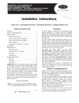
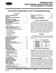
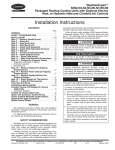
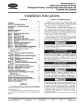
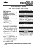
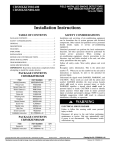
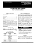
48/50HG014-028
48/50PG20-28
Large Rooftop Units with COMFORTLINK™ Controls
Economizer Package Accessory
Installation Instructions
Part Number CRECOMZR009E00 and CRECOMZR011E00
CONTENTS
GENERAL . . . . . . . . . . . . . . . . . . . . . . . . . . . . . . . . . . . . . . . . 1
PACKAGE USAGE AND CONTENTS . . . . . . . . . . . . . . 1
SAFETY CONSIDERATIONS . . . . . . . . . . . . . . . . . . . . . . 2
INSTALLATION . . . . . . . . . . . . . . . . . . . . . . . . . . . . . . . . . 2-6
CONFIGURATION . . . . . . . . . . . . . . . . . . . . . . . . . . . . . . 7-9
TROUBLESHOOTING. . . . . . . . . . . . . . . . . . . . . . . . . . . . 10
IMPORTANT: There are two different design revision
48/50HG units currently being produced. Because of
these differences, there are two different versions of
this accessory. This accessory literature covers accessories manufactured for units with design revision 1.
Design revision 0 units are not covered in this accessory book.
To determine the design revision, refer to the full unit
model number. See Fig. 1 for an example of an HG
model number. The design revision number in the model
number nomenclature is located in position 13.
DESIGN REVISION NUMBER
Position No.
Example:
9
10
11
12
13
14
15
16
4 8 H G D 0 1 6 A
1
2
3
4
5
6
7
8
A
C
6
1
1
A
A
Fig. 1 — Model Number Chart
GENERAL
IMPORTANT: Read these instructions completely
before attempting to install the accessory economizer.
The accessory economizer package uses microprocessorbased controls to sequence mechanical cooling with cool outdoor air (free cooling) to satisfy the cooling load and minimize
energy consumption. Free cooling can be used alone or in
conjunction with mechanical cooling.
The standard economizer uses an outdoor-air temperature
sensor to sense outdoor-air temperature. When the outdoor-air
temperature is between two configurable ambient temperatures,
the economizer is allowed to cool. These temperature configurations are the Economizer High Temperature Lockout (ECL.H)
and the Economizer Low Temperature Lockout (ECL.L). The
economizer will provide cooling when the outdoor temperature
is suitable as defined above by the lockout settings and if there is
a cooling demand. In addition, if an outdoor enthalpy sensor
accessory has been installed, then the enthalpy reading must
also be “low” before economizer cooling can occur.
When free cooling is available, the economizer sequences
free cooling with up to three stages of mechanical cooling to
maintain comfort in the space. When free cooling is not available, the economizer modulates to an adjustable minimum
position to maintain a supply of fresh air entering the building.
Optional barometric relief dampers provide natural building
pressurization control. An optional power exhaust system is
available for jobs requiring greater relief.
PACKAGE USAGE AND CONTENTS
UNIT SIZE
PART NO. QTY
CONTENTS
50TG500495
1 Damper Assy
50TG403161
1 Blockoff
50TG500303
1 Lower Hood Top Panel
50TG500301
1 Hood Side
50TG500302
1 Hood Side
50TG501090
2 Side Filter Guide
50TG500304
1 Upper Hood Top Panel
50TG500306
1 Filter Bracket
50TG501091
1 Filter Retainer Track
48/50PG20-24,
KH03DU350
3 Filter
48/50HG014-024
(CRECOMZR009E00) 50ZZ401127
1 Control Board
AL56AU130
5 No. 6 Screw
AL48AM307 10 1/4-in. Screw x 5/8-in.
AL31AZ308 25 1/4-in. Screw x 3/4-in.
AS41BZ133
3 Speed Nut
HY76TB110
5 Wire Tie
HY76TB125
1 Wire Tie
50TG402594
1 Harness Assy
—
1 Seal Strip
50TG500496
1 Damper Assy
50TG403163
1 Blockoff
50TG500303
1 Lower Hood Top Panel
50TG500301
1 Hood Side
50TG500302
1 Hood Side
50TG501090
2 Side Filter Guide
50TG500304
1 Upper Hood Top Panel
50TG500306
1 Filter Bracket
50TG501091
1 Filter Retainer Track
48/50PG28,
KH03DU350
3 Filter
48/50HG028
(CRECOMZR011E00) 50ZZ401127
1 Control Board
AL56AU130
5 No. 6 Screw
AL48AM307 10 1/4-in. Screw x 5/8-in.
AL31AZ308 22 1/4-in. Screw x 3/4-in.
AS41BZ133
3 Speed Nut
HY76TB110
5 Wire Tie
HY76TB125
1 Wire Tie
50TG402594
1 Harness Assy
—
1 Seal Strip
NOTE: If unit is already equipped with an outdoor air hood, hood
parts in the accessory will not be used and may be discarded.
Manufacturer reserves the right to discontinue, or change at any time, specifications or designs without notice and without incurring obligations.
PC 111
Catalog No. 534-80235
Printed in U.S.A.
Form 48/50H,P-18SI
Pg 1
6-05
Replaces: New
Book 1 1 4 4
Tab 1a 1b 6a 6b
SAFETY CONSIDERATIONS
Installation and servicing of air-conditioning equipment can
be hazardous due to system pressure and electrical components. Only trained and qualified service personnel should
install, repair, or service air-conditioning equipment.
Untrained personnel can perform basic maintenance functions of cleaning coils and filters and replacing filters. All other
operations should be performed by trained service personnel.
When working on air-conditioning equipment, observe precautions in the literature, tags and labels attached to the unit, and
other safety precautions that may apply.
Follow all safety codes. Wear safety glasses and work
gloves. Use quenching cloth for unbrazing operations. Have
fire extinguishers available for all brazing operations
OUTDOOR
AIR HOOD
IMPORTANT: Do not adjust the damper assembly.
The motor and damper have been pre-set and adjusted
for proper operation.
Fig. 2 — Outdoor Air Hood
INSTALLATION
Turn off unit power and lock out. Electrical shock and personal injury could result.
1. Prepare the unit for installation:
a. For units with two-position damper installed
remove the outdoor air hood. See Fig. 2. Unplug
the two-position damper and remove the assembly
from the outdoor air opening.
b. For units with manual damper installed, remove
the outdoor air hood and damper assembly.
c. For units with no outdoor air option installed,
remove the outdoor air intake cover. See Fig. 3.
2. Remove the side panel on the return end of the unit to expose the return section of the unit. Save the screws for use
later when replacing the panel. The inside of the unit will
contain a frame for installing the economizer as shown in
Fig. 4.
OUTDOOR
AIR INTAKE
COVER
Fig. 3 — Outdoor Air Intake Cover
Cover the duct opening as a precaution so objects cannot
fall into the return duct opening. Be sure to remove the
cover when installation is complete.
3. Remove the frame support brackets from both sides of
the frame inside the unit. See Fig. 4. Save the screws for
use later.
4. Uncrate the economizer assembly. Position the damper
assembly so that it will rest on the angle bracket support
at the bottom of the economizer frame inside the unit.
Slide the economizer into the unit. (See Fig. 5.) Secure
the damper assembly to the frame using the 1/4-in. x
5/ -in. screws provided.
8
5. Open the hinged control box compartment on the unit and
remove the control box cover. Save the screws for use later. Be sure not to place sharp objects on any surface that
could be damaged.
6. Install the economizer board (P/N 50ZZ401127) into the
control box using the no. 6, 3/4-in. screws provided. The
economizer board will mount into the pre-drilled holes on
the right side flange of the control box as shown in Fig. 6.
FRAME
SUPPORT
BRACKETS
(SIDE PANEL
REMOVED)
Fig. 4 — Frame Support Brackets
(Side Panel Removed)
2
11. Connect the motor plug to the plug provided with the
harness. (See Fig. 9.)
12. Install the insulated partition (block-off panel) by sliding
the panel into the unit from the side. The damper side of
the panel will slide along the top of the flange of the
damper assembly, between the return and outdoor air
damper blades. The panel should then be rotated upwards
so that the mounting holes align with the holes in the
panels at the end of the unit. Once in the correct position,
the partition will be horizontal inside the unit as shown in
Fig. 10.
13. Secure the partition to the frame using the screws saved
from Step 3, at the edges of the partition as shown in
Fig. 11.
14. The installation of the damper assembly is now complete.
Units with Outdoor Air Hood:
If the unit was equipped with an outdoor air hood, replace
the outer unit panels using the screws saved from the
earlier steps. Be sure to inspect all panel seals prior to
re-assembly and replace any seals that appear damaged.
Units without Outdoor Air Hood:
If the unit was not equipped with an outdoor air hood,
perform the following procedure to install the hood:
a. Make sure power supply is off.
b. Apply seal strip provided to back flange of both
hood sides where the hood side connects to the unit
back panel. See Fig. 12.
c. Apply seal strip provided to top flange of both
hood sides where hood sides connect to the hood
top panels. See Fig. 12.
d. Install hood sides to the back panels using the
screws provided. The sloped flanges point
outward. The drip edges of the side panels should
face outward as well. The filter guides attach to the
hood sides. The flanges should face inward to hold
the filters in place. See Fig. 12.
e. Apply seal strip along the entire length of the
bottom flange of the hood top. See Fig. 12.
f. Install the bottom part of the hood top using
4 screws provided. See Fig. 12.
Fig. 5 — Slide Economizer Assembly into Unit
7. Connect the wiring harness (P/N 50TG402594) into the
Economizer Control Board (ECB) plugs J1 and J2 and to
the Main Base Board plugs J2 and J3. See Fig. 7 and 8.
Be sure to connect the plugs with the proper orientation
such that the locking tabs capture the plug.
8. Connect the air quality plug marked “TB2-J10” from the
wiring harness into the TB-J10 plug on the main base
board. Be sure to connect the plug with the proper orientation such that the locking tabs capture the plug.
9. Pass the harness wires through the hole in the control box
and into the return air section. Be sure to secure the wires
so that they will not interfere with any moving parts.
10. Route the wire harness across the frame support as shown
in Fig 9. The motor plug (PL7) should be located at the
actuator side of the unit and snaps into the frame support
bracket. Be careful not to damage the wires. Route the
harness across the back of the top member of the frame as
shown and attach to the frame using the wire ties provided.
ComfortLink
ECONOMIZER
CONTROL BOARD
LOCATION
TB2-J10
Fig. 6 — Unit Control Box
3
g. Install the top part of the hood top using the
6 screws removed in Step 2. See Fig. 12.
h. Install the filter retainer track along the bottom
edge of the outdoor air hood using 4 screws
provided. For filter removal, remove the four
screws holding the filter retainer. The filters can
then be removed, cleaned, or replaced.
RELAYS
IMPORTANT: If the return duct opening was covered
prior to installation, remember to remove the covering so
as not to block off the return air to the unit.
ECB-J7
ECB-J9
15. Secure all wires so that they do not rub any sharp edges or
interfere with any moving parts.
16. Replace the control box cover using the screws saved
from Step 5. Economizer wiring is shown in Fig. 13.
17. Power can now safely be restored to the unit.
18. Install the three mist eliminating filters supplied into the
outdoor air inlet hood.
19. Inspect the unit to make sure all panels are properly
replaced and secured to the unit.
20. Configure the unit for use with economizer.
RED LED-STATUS
MAIN BASE BOARD
PART NUMBER
ECONOMIZER CONTROL BOARD
DIP
SWITCHES
(S1)
ECB-J2
ECB-J5
ECB-J4
Fig. 7 — Economizer Control Board
GREEN LEDLEN (LOCAL EQUIPTMENT NETWORK)
YELLOW LED CCN (CARRIER COMFORT NETWORK)
INSTANCE JUMPER
CEPL130346-01
J1
J4
STATUS
J2
J10
LEN
J3
CCN
J5
J6
J7
J8
Fig. 8 — Main Base Board
4
J9
WIRE
HARNESS
PLUG
PL7
Fig. 9 — Wire Harness Routing
INSULATED
BLOCK-OFF
PANEL
MOUNTING
HOLES
MOUNTING
HOLES
Fig. 10 — Economizer Block-Off Panel Location
Fig. 11 — Secure Block-Off Panel to Frame
5
TOP HOOD
SECTION
SEAL
STRIP
LOCATION
HOOD
SIDE
ADD
SEAL
STRIP
ADD
SEAL
STRIP
INNER
FILTER
TRACK
ADD
SEAL
STRIP
BOTTOM
HOOD
SECTION
ADD
SEAL
STRIP
FILTER
GUIDE
FILTER
RETAINER
FILTER
GUIDE
FILTER
HOOD
SIDE
UNIT
BACK
PANEL
Fig. 12 — Outdoor Air Hood Details
Fig. 13 — Economizer Wiring
6
CONFIGURATION
5. Use the arrow keys to change the configuration from
“NO” to “YES”, then press ENTER and ESCAPE to save
the setting.
6. If additional economizer control accessories have been
added or other configuration parameters are to be
changed from the factory defaults, then repeat the following steps:
a. Use the arrow keys to scroll up or down to the
parameter to change. Press ENTER once to select
the setting for configuration.
b. Press ENTER again. The configuration value will
flash.
c. Use the arrow keys to change the configuration
value.
d. Press ENTER and ESCAPE to save the setting.
7. Configuration of the ComfortLink control is now complete. Pressing ESCAPE multiple times will return the
display to the auto-scrolling setting.
8. Close and secure all access doors.
NOTE: The economizer static pressure drop must be
accounted for after installation. See Table 5. Refer to the
Controls and Troubleshooting literature for information on
adjusting the fans.
The ComfortLink™ control must be configured for economizer operation. The default values are for no economizer
and no IAQ accessories installed. These configurations are
changed through the Scrolling Marquee display or a Carrier
network device. The configuration parameters and factory
default values for economizer configuration and indoor air
quality configuration are shown in Tables 1-4.
NOTE: Consult the Controls, Start-Up, Operation, Service and
Troubleshooting Instructions for in-depth instructions on using
and configuring the ComfortLink control. The following instructions are for the Scrolling Marquee display or Navigator™
accessory.
1. The ComfortLink control must be configured to use the
economizer accessory. A password may be required to
edit the configurations depending on previous settings
configured in the unit. Default password is “1111”.
2. To configure the ComfortLink control, use the arrow keys
to scroll the red LED on the display to the “Configuration” position and press ENTER.
3. Use the arrow keys to scroll down until the display shows
“ECON”. This is the Economizer Configuration sub
mode. Press ENTER.
4. The control will display the Economizer Installed
(EC.EN) setting. Press ENTER once to select the EC.EN
setting for configuration. Press ENTER again for “NO”
to begin flashing.
Table 1 — Economizer Configuration Table (48/50PG Units)
ITEM
EXPANSION
ECON
→EC.EN
Economizer Configuration
Economizer Installed
→E.CTL
Economizer Control Type
→EC.MN
→EC MX
→H.4M
→H.20M
→EH.LO
→EL.LO
→UEFC
Econo Minimum Position
Econo Maximum Position
RH Sensor Value at 4mA
RH Sensor Value at 20mA
Econo Hi Temp Limit
Econo Lo Temp Limit
Unoccupied Free Cooling
→FC.TM
→FC.LO
→PE.EN
Free Cool PreOcc Time
Free Cool Low Temp Limit
Power Exhaust Installed
→PE.1
→PE.2
→EN.SW
PE Stage1 Econo Position
PE Stage2 Econo Position
Enthalpy Switch
→E.TRV
→E.MXB
→E.MXM
→E.MXT
→E.DBD
→EC.P
→EC.I
→EC.D
→EC.DT
Economizer Travel Time
Bottom Stage Max Econo
Middle Stage Max Econo
Top Stage Max Econo
Economizer PID Deadband
Economizer PID — kP
Economizer PID — kI
Economizer PID — kD
Economizer PID — rate
RANGE
UNITS
CCN TABLE/
SUB-TABLE
ECON_CFG
CCN
POINT
DEFAULT
Yes/No
ECONO
1=Digital, Position Feedback
2=Digital, Command Feedback
3=Analog Control
0 to 100
0 to 100
0 to 50
60 to 100
40 to 100
–30 to 50
0=Disabled
1=Entire Unoccupied Period
2=PreOccupancy Time
1 to 9999
0 to 70
Yes/No
ECON_CTL
No: no FIOP
Yes: FIOP
1
%
%
%
%
dF
dF
ECONOMIN
ECONOMAX
RH_4MA
RH_20MA
OATLECLH
OATLECLL
UEFC_CFG
30
100
0
100
65
0
2
min
dF
UEFCTIME
OATLUEFC
PE_ENABL
%
%
PE1_POS
PE2_POS
ENTHLCFG
120
50
No: no FIOP
Yes: FIOP
40
75
0: no FIOP
1: FIOP
sec
%
%
%
%
sec
sec
sec
sec
ECONOTRV
ECONMAXB
ECONMAXM
ECONMAXT
ECONBAND
ECONO_P
ECONO_I
ECONO_D
ECONO_DT
10 to 100
10 to 100
0=No Switch
1=Normally Open
2=Normally Closed
5 to 300
0 to 100
1 to 100
0 to 100
0 to 25
0.0 to 99.9
0.0 to 99.9
0.0 to 99.9
10.0 to 180.0
LEGEND
FIOP — Factory-Installed Option
7
150
50
35
0
3
2.5
0.1
1
15
Table 2 — Air Quality Configuration Table (48/50PG Units)
ITEM
EXPANSION
RANGE
AIR.Q
→IA.CF
Air Quality Configuration
IAQ Analog Input Config
→IA.FN
IAQ Analog Fan Config
→II.CF
IAQ Switch Input Config
→II.FN
IAQ Switch Fan Config
→AQ.MN
→EC.MN
→OVR.P
→OA.CF
Econo Min IAQ Position
Econo Minimum Position
IAQ Override Position
OAQ Analog Input Cfg
→OAQ.L
→AQD.L
→AQD.H
→DF.ON
→DF.OF
→I.4M
→I.20M
→O.4M
→O.20M
OAQ Lockout Limit
AQ Differential Low
AQ Differential High
Fan On AQ Differential
Fan Off AQ Differential
IAQ Sensor Value at 4mA
IAQ Sensor Value at 20mA
OAQ Sensor Value at 4mA
OAQ Sensor Value at 20mA
UNITS
CCN TABLE/
SUB-TABLE
IAQ_CFG
0=No IAQ
1=Demand Ventilation
2=Econ Position Override
3=Econ Min Position Control
0=Never
1=Only While Occupied
2=Always
0=No IAQ
1=DCV Normally Open
2=DCV Normally Closed
3=Override Normally Open
4=Override Normally Closed
0=Never
1=Only While Occupied
2=Always
0 to 100
0 to 100
0 to 100
0=No OAQ
1=Demand Ventilation
2=Outdoor Air Lockout
0 to 5000
0 to 5000
0 to 5000
0 to 5000
0 to 5000
0 to 5000
0 to 5000
0 to 5000
0 to 5000
CCN
POINT
DEFAULT
IAQANCFG
0: no FIOP
1: FIOP
IAQANFAN
0
IAQINCFG
0
IAQINFAN
0
IAQMINP
ECONOMIN
IAQOVPOS
OAQANCFG
10
30
100
0
OAQLOCK
DAQ_LOW
DAQ_HIGH
DAQFNON
DAQFNOFF
IAQ_4MA
IAQ_20MA
OAQ_4MA
OAQ_20MA
600
100
700
600
200
0
2000
0
2000
LEGEND
FIOP — Factory-Installed Option
Table 3 — Economizer Configuration Table (48/50HG Units)
SUBMODE
ITEM
DISPLAY
ECON
ITEM EXPANSION
COMMENT
Economizer Configuration
EC.EQ
YES/NO
Economizer Equipped Unit
E.CTL
X
Economizer Control Type
Default: 3
1 = Digital/Position
2 = Digital/Command
3 = Analog Control
MIN.P
XXX
Economizer Min Position
Default: 30 %
ECL.H
XX
Econ High Temp Lockout
Default: 65 F
ECL.L
XX
Econ Low Temp Lockout
Default: 0° F
Default: 2
0 = Disabled
1 = Unoccupied
2 = Preoccupancy
UEFC
X
Unoccupied Free Cooling
FC.TM
XXX
Free Cooling Preoccupancy Time
FC.LL
XX
Free Cooling Low Temperature Limit
Default: NO
Default: 120 sec
Default: 50 F
Default: 0
0: No Switch
1: Normal Open
2: Normal Close
Default: DSBL (ENBL if
equipped with power exhaust)
EN.SW
X
Enthalpy Switch Input
PE.EN
ENBL/DSBL
Power Exhaust Control
PE1.P
XXX
PE Stage1 Econo Position
Default: 40 %
PE2.P
XXX
PE Stage2 Econo Position
Default: 75 %
8
Table 4 — Indoor Air Quality Configuration Table (48/50HG Units)
SUBMODE
ITEM
DISPLAY
ITEM EXPANSION
IAQ
COMMENT
IAQ Configuration
Default:
0 if no IAQ sensor installed
1 if IAQ sensor installed
0 = No IAQ
1 = Demand Control Ventilation (DCV)
2 = Override IAQ
3 = Control Minimum Position
Default: 0
0 = Never
1 = Occupied
2 = Always
Default: 0
0 = Not Switch
1 = DCV NO
2 = DCV NC
3 = Override NO
4 = Override NC
Default: 0
0 = Never
1 = Only When Occupied
2 = Always
IA.CF
X
IAQ Input Configuration
IA.FN
X
Fan Enable for IAQ Input
II.CF
X
IAQ Level (Switch Input)
II.FN
X
IAQ Switch Input Fan CFG
AQ.MP
XXX
Minimum IAQ Position
Default: 10 %
MIN.P
XXX
Economizer Min Position
Default: 30 %
OVR.P
XXX
Econo Override Position
Default: 100%
OA.CF
X
OAQ Sensor Operation
Default: 0
0 = No OAQ
1 = DCV OAQ
2 = Lockout OAQ
OAQ.L
XXXX
OAQ Lockout Valve
Default: 600 ppm
AQD.L
XXX
AQ Differential Low
Default: 100 ppm
AQD.H
XXXX
AQ Differential High
Default: 700 ppm
DF.ON
XXX
Fan On AQ Differential
Default: 600 ppm
DF.OF
XXX
Fan Off AQ Differential
Default: 200 ppm
I.4M
XXXX
IAQ Sensor Value at 4MA
Default: 0 ppm
I.20M
XXXX
IAQ Sensor Value at 20MA
Default: 2000 ppm
O.4M
XXXX
OAQ Sensor Value at 4MA
Default: 0 ppm
O.20M
XXXX
OAQ Sensor Value at 20MA
Default: 2000 ppm
H.4M
XXX
RH Sensor Value at 4 mA
Default: 0%
Range: 0-100%
H.20M
XXX
RH Sensor Value at 20 mA
Default: 100%
Range: 0-100%
RH.SP
XX
Space RH Setpoint
Default: 50%
Range: 30-95%
RH.DB
XX
Space RH SetPnt Deadband
Default: 5%
Range: 2-20%
Table 5 — Accessory Economizer Static Pressure (in. wg)* — 48/50HG020-028 and 48/50PG20-28 Units
COMPONENT
Economizer
COMPONENT
Economizer
4,000
0.02
4,500
0.03
5,000
0.04
8,500
0.11
9,000
0.12
9,500
0.13
5,500
0.05
10,000
0.15
*The static pressure must be added to the external static pressure. The sum
and the evaporator entering-air cfm should then be used in conjunction with
the Fan Performance tables to determine blower rpm and watts.
9
CFM
6,000
0.06
CFM
10,500
0.16
6,500
0.07
7,000
0.08
11,000
0.17
7,500
0.09
11,500
0.19
8,000
0.10
12,000
0.20
TROUBLESHOOTING
and Possible Causes, Economizer Troubleshooting, and
Economizer Adjustment. See Table 6 for general economizer
service analysis.
Refer to the Controls, Start-Up, Operation, Service
and Troubleshooting Instructions for more information on
the following topics: Service Test, Diagnostic Alarm Codes
Table 6 — Economizer Service Analysis
PROBLEM
Damper Does Not Move.
POSSIBLE CAUSE
Indoor Fan is off.
Actuator is unplugged at motor or at
economizer board.
Unit is not configured for economizer.
Outdoor air temperature is above economizer
high temperature lockout.
Outdoor air temperature is below economizer
low temperature lockout.
Economizer Operation is Limited
to Minimum Position.
Communication loss to economizer board.
Damper is jammed.
Minimum position is set incorrectly.
Outdoor-air temperature is above economizer
high temperature lockout.
Outdoor-air temperature is below economizer
low temperature lockout.
Outdoor-air thermistor is faulty.
Low suction pressure problem with a compressor.
Economizer Position is Less
than Minimum Position.
IAQ is controlling minimum damper position.
Unit is in Unoccupied mode.
Economizer Does Not Return
to Minimum Position.
Outdoor Damper Not Fully Closed at
0% Commanded Position or Not Fully
Open at 100%.
Damper Does Not Close on
Power Loss.
Unit is operating under free cooling.
Economizer actuator is out of calibration.
Damper is jammed.
LEGEND
CCN — Carrier Comfort Network
IAQ — Indoor Air Quality
10
REMEDY
Check proper thermostat connection.
Unit is not configured for continuous fan
operation and the thermostat is not calling for
heating or cooling.
Unit is in Unoccupied mode and there is no
call for heating or cooling.
Blown fuse (FU1, FU2).
Tripped circuit breaker (CB1, CB2, CB3).
No power to the unit.
Unit is off via CCN command.
Check wiring connections.
Configure unit for economizer per the
instructions.
Adjust the high temperature lockout setting
if it is incorrect, otherwise, economizer is
operating correctly.
Adjust the low temperature lockout setting
if it is incorrect, otherwise, economizer is
operating correctly.
Check wiring connections.
Identify the obstruction and safely remove.
Adjust minimum position setting.
Adjust the high temperature lockout setting
if it is incorrect, otherwise, economizer is
operating correctly.
Adjust the low temperature lockout setting
if it is incorrect, otherwise, economizer is
operating correctly.
Replace outdoor air thermistor.
Economizer is operating correctly, identify
compressor problem.
Adjust the IAQ settings if incorrect,
otherwise the economizer is operating correctly.
Adjust unit occupied schedule if incorrect,
otherwise, economizer is operating correctly.
Economizer is operating correctly.
Enter Service Test mode and run the Calibrate
Economizer (Service Test→INDP→E.CAL)
procedure.
Identify the obstruction and safely remove.
9.
10.
11.
12.
13.
14.
Copyright 2005 Carrier Corporation
Manufacturer reserves the right to discontinue, or change at any time, specifications or designs without notice and without incurring obligations.
PC 111
Catalog No. 534-80235
Printed in U.S.A.
Form 48/50H,P-18SI
Pg 12
6-05
Replaces: New
Book 1 1 4 4
Tab 1a 1b 6a 6b