1
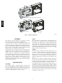
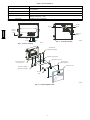
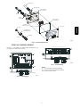
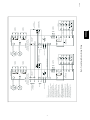
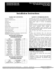
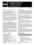
FACTORY INSTALLED SMOKE DETECTORS
FOR SMALL AND MEDIUM ROOFTOP UNITS
2 TO 25 TONS
Application Data
TABLE OF CONTENTS
PAGE
SAFETY CONSIDERATIONS . . . . . . . . . . . . . . . . . . . . . . . . . 1
PART NUMBERS . . . . . . . . . . . . . . . . . . . . . . . . . . . . . . . . . . . 1
APPLICABLE UNITS . . . . . . . . . . . . . . . . . . . . . . . . . . . . . . . . 1
GENERAL . . . . . . . . . . . . . . . . . . . . . . . . . . . . . . . . . . . . . . . . . 2
DESCRIPTIONS . . . . . . . . . . . . . . . . . . . . . . . . . . . . . . . . . . . . 2
FEATURES . . . . . . . . . . . . . . . . . . . . . . . . . . . . . . . . . . . . . . . . 3
INDICATORS . . . . . . . . . . . . . . . . . . . . . . . . . . . . . . . . . . . . . . 3
Understand the signal words DANGER, WARNING, and
CAUTION. These words are used with the safety--alert symbol.
DANGER identifies the most serious hazards which will result in
severe personal injury or death. WARNING signifies a hazard
which could result in personal injury or death. CAUTION is used
to identify unsafe practices which may result in minor personal
injury or product and property damage. NOTE is used to highlight
suggestions which will result in enhanced installation, reliability, or
operation.
WARNING
!
TYPICAL CONTROL WIRING . . . . . . . . . . . . . . . . . . . . . . . . 5
ELECTRICAL SHOCK HAZARD
ADDITIONAL FUNCTIONS WITH ROOFTOP
UNITS . . . . . . . . . . . . . . . . . . . . . . . . . . . . . . . . . . . . . . . . . . . 6
Failure to follow this warning could cause personal
injury or death.
SENSOR AND CONTROLLER TESTS . . . . . . . . . . . . . . . . . . 9
Disconnect all power to the unit before performing
maintenance or service. Unit may automatically start if
power is not disconnected. Tag disconnect switch with
lockout tag.
DETECTOR CLEANING . . . . . . . . . . . . . . . . . . . . . . . . . . . . 10
TROUBLESHOOTING . . . . . . . . . . . . . . . . . . . . . . . . . . . . . . 11
GUIDE SPECIFICATIONS . . . . . . . . . . . . . . . . . . . . . . . . . . . 12
UNIT SPECIFIC DATA . . . . . . . . . . . . . . . . . . . . . . . . . . . . . . 13
SAFETY CONSIDERATIONS
IMPORTANT: This equipment will provide safe and reliable
service when operated within design specifications. The equipment
should be operated and serviced only by authorized personnel who
have a thorough knowledge of system operation, safety devices
and emergency procedures.
Good judgement should be used in applying any manufacturer’s
instructions to avoid injury to personnel or damage to equipment
and property.
Follow all safety codes. Wear safety glasses and work gloves. Use
quenching cloth for unbrazing operations. Have fire extinguishers
available for all brazing operations.
Recognize safety information. This is the safety--alert symbol
.
When you see this symbol on the furnace and in instructions or
manuals, be alert to the potential for personal injury.
PART NUMBERS
HK28ZT001
Controller module
HK50ZT001
Sensor module with exhaust tube
RN20ZT008
8--- in. sample tube
RN20ZT024
24--- in. sample tube
RN20ZT036
36--- in. sample tube
RN20ZT042
42--- in. sample tube
KA99ZT003
SD--- TRK4 remote test--- reset station,
keyed
APPLICABLE UNITS
48/50HE, 50HEQ003--- 006
581C, 551C, 549C024--- 060
50HJQ, TFQ004--- 006
548F, 549F036--- 102
48/50HJ, TM004--- 014
581B, 551B036--- 300
48/50TF, 004--- 014, TJ016--- 028
580F, 558F036--- 300
48/50PG03--- 28
48/50HG014--- 028
HKRNKA
Combination duct smoke sensor and controller
Duct smoke sensor
Duct smoke sensor
controller
C07284
Fig. 1 -- Controller and Detector
GENERAL
This document provides information and guidance on smoke
detectors that are factory installed on the applicable units.
For field installed smoke detector applications, these same
detectors may be used. However, unless a field installed kit is
provided, the installer must determine and install the detectors in a
manner consistent with the application and in compliance with all
codes. Due to the wide variety of both of these issues, field
installation kits are not available for all unit models.
The primary intent of these detectors is to shut down the unit’s air
delivery services upon an alarm trip. They are not designed as a
substitute for an open area smoke detector nor a substitute for early
warning detection or a replacement for a building’s regular fire
detection system. Smoke detectors are not designed to detect toxic
gases which can build up to hazardous levels in some fires. These
devices will not operate without electrical power. As fires
frequently cause power interruptions, it is recommended that the
installer further safeguards with your local fire protection specialist
and code enforcement agency.
DESCRIPTIONS
Controller
The controller includes a controller housing, a printed circuit
board, and a clear plastic cover. The controller can be connected to
one or two compatible duct smoke sensors. The clear plastic cover
is secured to the housing with a single captive screw for easy
access to the wiring terminals. (See Fig. 1, 3, and 4.)
Sensor
The sensor includes a plastic housing, a printed circuit board, a
clear plastic cover, an exhaust tube, and a sampling tube. The
exhaust tube and sampling tube are attached during installation.
The sampling tube varies in length depending on the size of the
rooftop unit. The clear plastic cover permits visual inspections
without having to disassemble the sensor. The cover attaches to the
sensor housing using four captive screws and forms an airtight
chamber around the sensing electronics.
System
The smoke detector comprises a four--wire controller and one or
two sensors. Its primary function is to shut down the rooftop unit
in order to prevent smoke from circulating throughout the
building. It is not to be used as a life saving device. When these
smoke detectors are factory installed on the units listed above, no
additional sampling tubes are required to be field installed. (See
Fig. 5.)
The controller is designed for multiple operating voltages and
provides relay contacts for connection to fire alarm systems, HVAC
controls, and other auxiliary functions. A remote test/reset station
can be connected to the controller to provide these functions.
For installations using two sensors, the duct smoke detector does
not differentiate which sensor signals an alarm or trouble condition.
The sensor uses a process called differential sensing to prevent
gradual environmental changes from triggering false alarms. A
rapid change in environmental conditions, such as smoke from a
fire, causes the sensor to signal an alarm state but dust and debris
accumulated over time does not.
2
!
CAUTION
EQUIPMENT DAMAGE HAZARD
Failure to follow this caution may result in damage to
equipment.
Excess temperature differentials between the ambient air and
the sampled air can produce unwanted condensation inside the
sensor, which may cause the sensor to function improperly.
Precautions should be taken to limit the temperature range and
the amount of condensation to which the sensor is exposed.
FEATURES
The smoke sensor incorporates the following features:
S Environmental compensation with differential sensing for
reliable, stable, and drift--free sensitivity.
S Magnet--activated test/reset switch on sensors.
S PCB mounted photoelectric sensor with on--board intelligence.
S Cover tamper switch for added security.
S Alarm, Trouble, Dirty, and Power status LEDs. (See Table 1 and
Fig. 2.)
S Extended temperature and air velocity ranges.
S Capable of adding an additional sensors (for a total of two) using
the same controller.
S Multiple operating voltages.
S No tools required to access field connection terminals.
S Recessed momentary switch for test/reset of the detector.
S One set of normally open alarm initiation contacts for
connection to an initiating device circuit on a fire alarm control
panel.
S Two Form--C auxiliary alarm relays for interface with rooftop
unit or other equipment.
S One Form--C supervision (trouble) relay to control the operation
of the Trouble LED on a remote test/reset station.
S Can be wired to up to 14 other duct smoke detectors for multiple
fan shutdown applications.
Alarm State
The smoke detector enters the alarm state when the amount of
smoke particulate in the sensor’s sensing chamber exceeds the
alarm threshold value. (See Table 1.) Upon entering the alarm
state:
S The sensor’s Alarm LED and the controller’s Alarm LED turn
on.
S The contacts on the controller’s two auxiliary relays switch
positions.
S The contacts on the controller’s alarm initiation relay close.
S The controller’s remote alarm LED output is activated (turned
on).
S The controller’s high impedance multiple fan shutdown control
line is pulled to ground Trouble state.
The SuperDuct duct smoke detector enters the trouble state under
the following conditions:
S A sensor’s cover is removed and 20 minutes pass before it is
properly secured.
S A sensor’s environmental compensation limit is reached (100%
dirty).
S A wiring fault between a sensor and the controller is detected.
An internal sensor fault is detected upon entering the trouble state:
S The contacts on the controller’s supervisory relay switch
positions. (See Fig. 3.)
S If a sensor trouble, the sensor’s Trouble LED the controller’s
Trouble LED turn on.
S If 100% dirty, the sensor’s Dirty LED turns on and the
controller’s Trouble LED flashes continuously.
S If a wiring fault between a sensor and the controller, the
controller’s Trouble LED turns on but not the sensor’s.
NOTE: All troubles are latched by the duct smoke detector. The
trouble condition must be cleared and then the duct smoke detector
must be reset in order to restore it to the normal state.
Multiple Detector Operation
The interconnect feature of the smoke detector allows up to 15
smoke detectors to be connected to each other, typically for
multiple fan shutdown applications. When one of the smoke
detectors goes into alarm, it operates as described above. On the
remaining smoke detectors not in alarm, only the following occurs:
S The auxiliary relay contacts switch positions.
S The remote LED output is activated (turned on).
INDICATORS
Normal State
The smoke detector operates in the normal state in the absence of
any trouble conditions and when its sensing chamber is free of
smoke. In the normal state, the Power LED on both the sensor and
the controller are on and all other LEDs are off.
3
HKRNKA
Air is introduced to the duct smoke detector’s sensing chamber
through a sampling tube that extends into the HVAC duct and is
directed back into the ventilation system through an exhaust tube.
The difference in air pressure between the two tubes pulls the
sampled air through the sensing chamber. When a sufficient
amount of smoke is detected in the sensing chamber, the sensor
signals an alarm state and the controller automatically takes the
appropriate action to shut down fans and blowers, change over air
handling systems, notify the fire alarm control panel, etc.
Table 1 – Detector Indicators
Control or Indicator
Description
Magnetic test/reset switch
Alarm LED
Resets the sensor when it is in the alarm or trouble state. Activates or tests the sensor when it is in
the normal state.
Indicates the sensor is in the alarm state.
Trouble LED
Indicates the sensor is in the trouble state.
Dirty LED
Indicates the amount of environmental compensation used by the sensor
(flashing continuously = 100%)
Power LED
Indicates the sensor is energized.
Trouble
HKRNKA
Alarm
Power
Magnetic
test/reset
switch
Test/reset
switch
Alarm
Trouble
Power
Dirty
C07298
Fig. 3 -- Controller Assembly
C07297
Fig. 2 -- Detector Assembly
Conduit nuts
(supplied by installer)
Conduit support plate
Terminal block cover
Controller housing
and electronics
Cover gasket
(ordering option)
Controller cover
Conduit couplings
(supplied by installer)
Fastener
(2X)
C07299
Fig. 4 -- Controller Exploded View
4
Exhaust tube
Exhaust gasket
Sensor housing
and electronics
See
Detail A
Intake
gasket
Cover gasket
(ordering option)
TSD-CO2
(ordering option)
HKRNKA
Sensor cover
Plug
Sampling tube
(ordered separately)
Coupling
Detail A
C07300
Fig. 5 -- Detector Exploded View
TYPICAL CONTROL WIRING
See Fig. 6, 7, and Table 2 for terminal wiring arrangements. See
Fig. 8 and 9 for smoke detector wiring.
2 0 19 18 17 16 15 14 13 12 11
TB3
L
J1
N
10 9
8
7
6
5
4
3
2
1
2 1
J2
C07302
Fig. 7 -- Terminal Block
TB3
NOTES:
J1 = RJ ---45 connection to first detector assembly
J2 = RJ ---45 connection to second detector assembly
TB3 = Terminal connection board
Nonpower-limited
Power-limited
C07301
Fig. 6 -- Terminal Block
5
HKRNKA
Table 2 – Terminal Block Connections
Terminal No.
Name
Terminal No.
Name
1
AUX (--- )
11
Not Used
2
Reset
12
Multi--- Shutdown
3
SUPV Contact COM
13
SUPV Contact NO
4
Alarm Contact COM
14
SUPV Contact NC
5
Alarm Contact NO
15
REM Alarm LED Out
6
AUX 1 Contact COM
16
AUX 1 Contact NC
7
AUX 2 Contact NO
17
AUX 1 Contact NO
8
AUX 2 Contact NC
18
AUX 2 Contact COM
9
24V AC/DC In (+)
19
18 VDC Output (+)
10
24V AC/DC In (--- )
20
18 VDC Output (--- )
N
AC Neutral
TB3--- 1
Not Used
L
AC Line
TB3--- 2
Not Used
ADDITIONAL FUNCTIONS WITH
ROOFTOP UNITS
The factory installed smoke detectors are factory wired to
immediately shut down the unit upon an alarm trip. However, in
many situations, additional functions such as remote test stations,
remote indicators, and auxiliary relays are also desired or required
by code. These functions are easily supported by the factory
installed smoke detector; however, since they typically involve
incorporation with the building system and exact details are
frequently application specific, these additional functions must be
wired in the field.
As shown in Table 1, additional functionality includes but is not
limited to the functions below. Fig. 6--11 show typical wiring
integration to allow integration of the smoke detectors with various
other building systems. For the remote indication and/or test
station, the Remote Keyed Attenuator SD--TRK4 (p/n
KA99ZT00)3 is recommended. See Fig. 9 and guide specification
section.
S Building alarm initiation
S Remote indicators
S Multiple fan shutdown
S Remote test station
S Auxiliary relays
The smoke detector system is also frequently desired to be
integrated into rooftop unit for the following functions:
S Smoke purge
S Pressurization
S Smoke Exhaust
These functions are typically only required after an alarm has been
initiated. They require integration with the unit economizer and/or
power exhaust and are typically activated at the specific request of
the fire department. See the applicable unit wiring diagrams for
guidance specifics on these functions with respect to the unit in
question.
Smoke Purge
Smoke Purge is the operation of the unit’s indoor fan to bring air in
the building and push air out the building, supplemented by a
Power Exhaust. Since the Outdoor Air (OA) damper blades and
the Return Air (RA) damper blades move in opposite directions,
this feature results in the OA dampers fully open and the RA
dampers fully shut.
Pressurization and Smoke Exhaust
Pressurization and Smoke Exhaust are typically used together
when there are multiple units on application. The Fire Marshall
places the rooftop unit for the affected zone in the Smoke Exhaust
mode and all others in the Pressurization mode, thus clearing the
smoke in the affected zone. Pressurization is the operation of the
unit’s indoor fan to create a positive pressure inside the building by
fully opening the OA dampers and turning on the indoor fan.
Since the OA damper blades and the RA damper blades move in
opposite directions, this feature results in the OA dampers fully
open and the RA dampers fully shut. Smoke Exhaust is very
similar to Smoke Purge, except that this function requires the
economizer OA dampers to be fully shut and the Power Exhaust to
be on. Since the OA damper blades and the RA damper blades
move in opposite directions (for Carrier economizers), this feature
results in the OA dampers fully shut and the RA dampers fully
open.
6
7
Notes
JP1
First controller
120V/220V/240V [5]
[9] Wiring is supervised by the controller.
Maximum wire distance is 100 ft.
[8] Wiring is nonsupervised. Wire resistance
from first controller to last controller can not
exceed 5 ohms.15 controllers, max.
[7] Control panel provides supervision and
determines wire requirements
[6] No more than two remote test/reset
stations can be connected at the same time.
Wiring is nonsupervised. Maximum wire
resistance is 10 ohms per wire.
[5] Move JP3 to the 230V position only
when using 220V or 240V to operate the
controller
[4] End-of-line resistor required on last
controller only. Value is determined by the
fire alarm control panel.
[3] Supervision relay contacts shown in
normal condition. Contacts change over on
sensor or controller trouble.
[2] Alarm initiation contacts shown in normal
condition. Contacts close on alarm.
14
18 Vdc ( −)
120V/220V/240V [5]
+
−
Reset/Test
Alarm
Power
Fig. 8 -- Typical Smoke Detector System Wiring
2
3
2
20
1
4
5
Trouble
SD-TRK4
Auxiliary
equipment
15
19
13
18 Vdc ( +)
+
2
Supervision relay
contacts [3]
Wire must be
added by installer
3
−
1
JP1
Last controller
N
L
9
10
4
5
14
2
1
TB3
JP3
8
18
7
16
6
17
−
18 Vdc ( −)
18 Vdc ( +)
+
2
3
1
4
5
Reset/Test
Alarm
Power
Trouble
SD-TRK4
Auxiliary
equipment
Supervision relay
(supplied by installer)
EOLR [4]
(supplied by installer)
Auxiliary
equipment
Auxiliary
equipment
HKRNKA
20
2
15
19
13
Supervision relay
contacts [3]
120 V
230V
Wire must be
added by installer
3
JP2
Alarm initiation
contacts [2]
Do not use looped wires under
terminals 5 and 4. Break wire runs
to provide supervision of connections.
1
TB3
Multiple fan shutdown [8]
J2
J1
CAUTION
RJ-45 cable [9]
24V AC/DC
J1
RJ-45 cable [9]
1
120V
JP3
J1
2nd sensor [1]
Supervision relay
(supplied by installer)
Auxiliary
equipment
Auxiliary
equipment
12
JP2
230V
Alarm initiation
contacts [2]
8
18
7
16
6
17
1st sensor
12
N
L
9
10
−
+
4
5
−
+
Do not use looped wires under
terminals 5 and 4. Break wire runs
to provide supervision of connections.
24V AC/DC
[1] Remove JP1 when the controller is
connected to two sensors
J2
J1
CAUTION
RJ-45 cable [9]
RJ-45 cable [9]
Initiating device circuit
on fire alarm
control panel [7]
J1
2nd sensor [1]
J1
1st sensor
C07303
C07318
HKRNKA
Fig. 10 -- Controller TB3 Connections
C07317
Fig. 9 -- Remote Keyed Actuator
First controller
+
IDC circuit on
fire alarm
control panel
5
Ð
Alarm
Alarm
contacts
4
4
Trouble contacts
Trouble contacts
14
1
15
5
Alarm
contacts
Remote test station
Controller
Last controller
3
14
EOLR
3
End-of-line resistor required on
last device for circuit supervision.
Use resistor value specified by the
fire alarm panel manufacturer.
4
19
Power
13
3
5
2
3
20
2
Trouble
Fire alarm initiating circuit wiring
Reset/Test
Controller
Remote LED indicator
15
+
20
Ð
Note: For applications where only the Alarm LED
and Reset/Test switch is required, wiring the
Power LED and Trouble LED is optional.
Alarm
Remote test station wiring
Remote LED indicator wiring
First
controller
Controller
Controller
10
24 VAC/DC
9
A
120 V
B
220/240 V
C
Power input wiring
Second
controller
12
12
1
1
17
6
Auxiliary
equipment
17
16
7
18
Auxiliary
equipment
System control,
thermostat, or
power
17
6
6
16
16
Fan control
mechanism
8
Auxiliary relay wiring
Nexty
controller
System control,
thermostat, or
power
Fan control
mechanism
Multiple fan shutdown interconnect wiring
C07319
Fig. 11 -- Typical Smoke Detector Wiring -- Exploded View
8
Dirty Controller Test Procedure
1. Press the controller’s test/reset switch for two seconds.
2. Verify that the controller’s Trouble LED flashes.
Sensor Alarm Test
The sensor alarm test checks a sensor’s ability to signal an alarm
state. This test requires that you use a field provided SD--MAG
test magnet.
!
CAUTION
OPERATIONAL TEST HAZARD
Failure to follow this caution may result in personnel and
authority concern.
Dirty Sensor Test
The dirty sensor test provides an indication of the sensor’s ability
to compensate for gradual environmental changes. A sensor that
can no longer compensate for environmental changes is considered
100% dirty and requires cleaning or replacing. You must use a field
provided SD--MAG test magnet to initiate a sensor dirty test. The
sensor’s Dirty LED indicates the results of the dirty test as shown
in Table 3.
!
This test places the duct detector into the alarm state. Unless
part of the test, disconnect all auxiliary equipment from the
controller before performing the test. If the duct detector is
connected to a fire alarm system, notify the proper authorities
before performing the test.
CAUTION
OPERATIONAL TEST HAZARD
Failure to follow this caution may result in personnel and
authority concern.
Holding the test magnet against the sensor housing for more
than seven seconds will put the duct detector into the alarm
state and activate all automatic alarm responses.
Sensor Alarm Test Procedure
1. Hold the test magnet where indicated on the side of the
sensor housing for seven seconds.
2. Verify that the sensor’s Alarm LED turns on.
3. Reset the sensor by holding the test magnet against the
sensor housing for two seconds.
4. Verify that the sensor’s Alarm LED turns off.
Table 3 – Dirty LED Test
Flashes
Description
1
0--- 25% dirty. (Typical of a newly installed
detector)
Controller Alarm Test
2
25--- 50% dirty
The controller alarm test checks the controller’s ability to initiate
and indicate an alarm state.
3
51--- 75% dirty
4
76--- 99% dirty
!
CAUTION
Dirty Sensor Test Procedure
1. Hold the test magnet where indicated on the side of the
sensor housing for two seconds.
2. Verify that the sensor’s Dirty LED flashes.
OPERATIONAL TEST HAZARD
Failure to follow this caution may result in personnel and
authority concern.
This test places the duct detector into the alarm state.
Disconnect all auxiliary equipment from the controller before
performing the test. If the duct detector is connected to a fire
alarm system, notify the proper authorities before performing
the test.
Controller Alarm Test Procedure
1. . Press the controller’s test/reset switch for seven seconds.
2. Verify that the controller’s Alarm LED turns on.
3. Reset the sensor by pressing the test/reset switch for two
seconds.
4. Verify that the controller’s Alarm LED turns off.
Changing the Dirt Sensor Test
By default, sensor dirty test results are indicated by:
S The sensor’s Dirty LED flashing.
S The controller’s Trouble LED flashing.
S The controller’s supervision relay contacts toggle.
The operation of a sensor’s dirty test can be changed so that the
controller’s supervision relay is not used to indicate test results.
When two detectors are connected to a controller, sensor dirty test
operation on both sensors must be configured to operate in the
same manner.
!
OPERATIONAL TEST HAZARD
Dirty Controller Test
Failure to follow this caution may result in personnel and
authority concern.
The dirty controller test checks the controller’s ability to initiate a
dirty sensor test and indicate its results.
!
CAUTION
Changing the dirty sensor test operation will put the detector
into the alarm state and activate all automatic alarm responses.
Before changing dirty sensor test operation, disconnect all
auxiliary equipment from the controller and notify the proper
authorities if connected to a fire alarm system.
CAUTION
OPERATIONAL TEST HAZARD
Failure to follow this caution may result in personnel and
authority concern.
Pressing the controller’s test/reset switch for longer than seven
seconds will put the duct detector into the alarm state and
activate all automatic alarm responses.
9
HKRNKA
SENSOR AND CONTROLLER TESTS
DETECTOR CLEANING
To Configure the Dirty Sensor Test Operation
1. Hold the test magnet where indicated on the side of the
sensor housing until the sensor’s Alarm LED turns on and
its Dirty LED flashes twice (approximately 60 seconds).
2. Reset the sensor by removing the test magnet then holding
it against the sensor housing again until the sensor’s Alarm
LED turns off (approximately 2 seconds).
Cleaning the Smoke Detector
Clean the duct smoke sensor when the Dirty LED is flashing
continuously or sooner if conditions warrant.
!
Remote Station Test
OPERATIONAL TEST HAZARD
The remote station alarm test checks a test/reset station’s ability to
initiate and indicate an alarm state.
!
Failure to follow this caution may result in personnel and
authority concern.
CAUTION
If the smoke detector is connected to a fire alarm system, first
notify the proper authorities that the detector is undergoing
maintenance then disable the relevant circuit to avoid
generating a false alarm.
HKRNKA
OPERATIONAL TEST HAZARD
Failure to follow this caution may result in personnel and
authority concern.
1. Disconnect power from the duct detector then remove the
sensor’s cover. (See Fig. 12.)
2. Using a vacuum cleaner, clean compressed air, or a soft
bristle brush, remove loose dirt and debris from inside the
sensor housing and cover.
Use isopropyl alcohol and a lint--free cloth to remove dirt
and other contaminants from the gasket on the sensor’s
cover.
3. Squeeze the retainer clips on both sides of the optic housing
then lift the housing away from the printed circuit board.
4. Gently remove dirt and debris from around the optic plate
and inside the optic housing.
5. Replace the optic housing and sensor cover.
6. Connect power to the duct detector then perform a sensor
alarm test.
This test places the duct detector into the alarm state. Unless
part of the test, disconnect all auxiliary equipment from the
controller before performing the test. If the duct detector is
connected to a fire alarm system, notify the proper authorities
before performing the test.
SD-- TRK4 Remote Alarm Test Procedure
1. Turn the key switch to the RESET/TEST position for seven
seconds.
2. Verify that the test/reset station’s Alarm LED turns on.
3. Reset the sensor by turning the key switch to the
RESET/TEST position for two seconds.
4. Verify that the test/reset station’s Alarm LED turns off.
Remote Test/Reset Station Dirty Sensor Test
The test/reset station dirty sensor test checks the test/reset station’s
ability to initiate a sensor dirty test and indicate the results. It must
be wired to the controller as shown in Fig. 8 and configured to
operate the controller’s supervision relay. For more information,
see “Changing sensor dirty test operation.”
!
CAUTION
Sampling
tube
CAUTION
HVAC duct
Sensor
housing
Optic
plate
Airflow
OPERATIONAL TEST HAZARD
Failure to follow this caution may result in personnel and
authority concern.
Retainer
clip
If the test/reset station’s key switch is left in the RESET/TEST
position for longer than seven seconds, the detector will
automatically go into the alarm state and activate all automatic
alarm responses.
Optic
housing
C07305
Fig. 12 -- Sensor Cleaning Diagram
!
CAUTION
OPERATIONAL TEST HAZARD
Failure to follow this caution may result in personnel and
authority concern.
Holding the test magnet to the target area for longer than seven
seconds will put the detector into the alarm state and activate
all automatic alarm responses.
Dirty Sensor Test Using an SD-- TRK4
1. Turn the key switch to the RESET/TEST position for two
seconds.
2. Verify that the test/reset station’s Trouble LED flashes.
10
Sensor’s Power LED is Off
1. Check the controller’s Power LED. If it is off, determine
why the controller does not have power and make the
necessary repairs.
2. Check the wiring between the sensor and the controller. If
wiring is loose or missing, repair or replace as required.
Controller’s Trouble LED is On
1. Check the Trouble LED on each sensor connected to the
controller. If a sensor’s Trouble LED is on, determine the
cause and make the necessary repairs.
2. Check the wiring between the sensor and the controller. If
wiring is loose or missing, repair or replace as required.
Controller’s Power LED is Off
1. Make sure the circuit supplying power to the controller is
operational. If not, make sure JP2 and JP3 are set correctly
on the controller before applying power.
2. Verify that power is applied to the controller’s supply input
terminals. If power is not present, replace or repair wiring as
required.
Controller’s Trouble LED is Flashing
1. One or both of the sensors is 100% dirty.
2. Determine which Dirty LED is flashing then clean that
sensor assembly as described in the detector cleaning
section.
Sensor’s Trouble LED is On
1. Check the sensor’s Dirty LED. If it is flashing, the sensor is
dirty and must be cleaned.
2. Check the sensor’s cover. If it is loose or missing, secure the
cover to the sensor housing.
3. Replace sensor assembly.
Remote Test/Reset Station’s Trouble LED Does
Not flash When Performing a Dirty Test, But the
Controller’s Trouble LED Does
1. Verify that the remote test/station is wired as shown in Fig.
8. Repair or replace loose or missing wiring.
2. Configure the sensor dirty test to activate the controller’s
supervision relay. See “Changing sensor dirty test operation.”
Sensor’s Trouble LED is On, But the Controller’s
Trouble LED is OFF
Remove JP1 on the controller.
11
HKRNKA
TROUBLESHOOTING
GUIDE SPECIFICATIONS
Controller Specifications
Detector Specifications
A. Dimensions
S Controller only: 6.75 x 5.45 x 1.90 in.
S Controller and detector: 14.51 x 5.45 x 1.90 in.
A. Sensor
S 8.70 x 5.45 x 1.90 in.
B. Operating Environment
S Temperature: --20_ to 158_F (--29_ to 70_C)
S Humidity: 10% to 93% RH, non--condensing
HKRNKA
C. Wire Size
S High voltage terminals: 12--22 AGW
S All others: 14--22 AGW
D. Operating Voltages
S 20--29 VAC, 50/60 Hz
S 120 VAC, 50/60 Hz
S 220/240 VAC, 50/60 Hz
E. Operating Current
S 20--29VDC: 175 mA
S 24 VAC: 500 mA at 50/60 Hz
S 120 VAC: 100 mA at 50 Hz
75 mA at 60 Hz
S 220/240 VAC: 53 mA at 50 Hz
40 mA at 60 Hz
F. LED Indicators
S Red (Alarm)
S Yellow (Trouble)
S Green (Power)
G. Relays
S Alarm initiation relay
Quantity: 1
Style: Normally open
Ratings: 2.0A at 30 VDC (resistive)
S Auxiliary relay
Quantity: 1
Style: Form C
Ratings: 10A at 30 VDC, 10A at 250 VAC
S Supervision (trouble) relay
Quantity: 1
Style: Form C
Ratings: 2.0A at 30 VDC (resistive)
B. Smoke Detection Method
S Photoelectric
C. Operating Environment
S Same as controller
D. Air Velocity (Min--Max)
S 100--4,000 ft/min
E. Pressure Differential (Min--Max)
S 0.005--1.00 in.
F. Sensitivity
S 0.67 to 2.48 %obscuration/ft
S Wire size: 14 to 22 AGW
G. Reset Time
S 2 second maximum
H. Power Up Time
S 8 second maximum
I. Alarm Test Response Time
S 5 to 7 second
J. LED Indicators
S Red (Alarm)
S Yellow (Trouble)
S Yellow (Dirty)
S Green (Power)
Remote Keyed Attenuator and
Test/Reset Station Specifications (KA--99ZT--003)
A. Compatibility with electrical boxes
S North American 1--gang box
S Standard 4--in. square box, 1--1/2 in. deep, with 1--gang
cover
B. LED Indicators
S Red (Alarm)
S Yellow (Trouble)
S Green (Power)
C. LED Type
S Clear lens
D. Wire Size
S 14 to 22 AWG
E. Resistance per Wire
S 10 Ω, max
F. Operating Current
Same as controller specification
G. Operating Voltages
S 24 Vdc, 24V at 50/60 Hz
S 120V at 50/60 Hz
S 220/240V at 50/60 Hz
H. Compatible Detectors
S SuperDuct Four--Wire smoke detectors
I. Operating Environment
S Temperature: 32_ to 131_F (0_ to 55_C)
S Humidity: 93% RH, non--condensing
J. Storage Temperature
S --20_ to 60_C (--4_ to 140_F)
12
UNIT SPECIFIC DATA
Applicable Units:
48/50HE, 50HEQ003--006
581C, 551C, 549C024--060
48/50HJ, TM, TF004--014
581B, 551B036--150
50HJQ, TFQ004--012
548F, 549F036--102
2. For applications with a factory installed economizer, the
economizer is modified to incorporate the return air sample
tube. For field installed economizers, the installer may
desire to modify the economizer also; however, the factory
modification does not need to be replicated.
3. Factory provided detectors are wired such that if the unit is
shut down on any other alarm (such as high head pressure)
the detectors will still have power and can still provide a
unit trip function.
4. On units with PremierLinkt and Humidi--MiZert
Adaptive Dehumidification System, it is recommended that
the installing contractor route the two pink DEHUM wires
through one of the smoke controller N.C. auxiliary relays.
580F, 558F036--151
General
HKRNKA
1. For these units, the factory installed smoke detectors are
typically installed as shown below. For horizontal return
applications, the return air sample tube is moved in the field
to extend across the horizontal opening.
C07413
Fig. 13 -- Typical TB--4 Wiring Diagram
13
HKRNKA
C07304
Fig. 14 -- Smoke Detector Wiring Diagram
(To be used in conjunction with rooftop unit wiring diagram)
14
HKRNKA
Controller
Module
Supply Air Detector
Module
C07306
Fig. 15 -- Typical Supply Air Return Air Detector Location, 2--12.5 Ton Units
(2--6 Ton Unit Shown)
Return Air Detector module
(shipping position shown)*
Controller module
Return Air Detector Sampling Tube
* RA detector must be moved from shipping position to operating position by installer
C07307
Fig. 16 -- Typical Return Air Detector Location, 2--12.5 Ton Units
15
Applicable Units:
48/50HJ015--017
General
581A, 551A155--180
580F, 579F, 559F180--300
50HJQ014--016
542J150--180
HKRNKA
48/50TM, TJ016--028
For these units, the factory installed smoke detectors are typically
installed as shown below. For horizontal return applications, the
return air sample tube is moved in the field to extend across the
horizontal opening.
For applications with a factory installed economizer, the
economizer is modified to incorporate the return air sample tube.
For field installed economizers, the installer may desire to modify
the economizer also, however, the factory modification does not
need to be replicated.
Return Air sample tube
Detector and
Controller
C07414
Fig. 17 -- Typical Return Air Detector Location
16
Applicable Units:
48/50HJ020--028
General
For these units, the following accessory installation kits are
available for field installed smoke detectors: CRSMKDET001D00,
CRSMKSUP001B00, CRSMKSEN001A00. See these kits as
applicable for additional information.
581A, 551A210--300
48/50HG014--028
48/50PG020--028
Controller
HKRNKA
Tube Location
Return Air Detector
C1/B1
B1/A2
A1
C07415
Fig. 18 -- Return Air Detector Location
Supply Air Detector
Blower
C07416
Fig. 19 -- Supply Air Detector Location (Top View of Unit)
17
Applicable Units:
48/50PG03--16
General
HKRNKA
For these units, the factory installed smoke detectors are typically
installed as shown below. For horizontal return applications, the
return air sample tube is moved in the field to extend across the
horizontal opening.
For applications with a factory installed economizer, the
economizer is modified to incorporate the return air sample tube.
For field installed economizers, the installer may desire to modify
the economizer also, however, the factory modification does not
need to be replicated.
Return Air Detector
and Controller
Supply Air Detector
C07417
Fig. 20 -- Typical 48/50PG 2--15 Ton Detector Locations
18
HKRNKA
C08017
Fig. 21 -- Typical Wiring for 48/50 Unit with Humidi--MiZer System and Factory--Installed Smoke Detectors
19
HKRNKA
Copyright 2008 CAC / BDP D 7310 W. Morris St. D Indianapolis, IN 46231
Printed in U.S.A.
Edition Date: 2/08
Manufacturer reserves the right to change, at any time, specifications and designs without notice and without obligations.
20
Catalog No:HKRNKA ---1XA
Replaces: NEW