1
INSTALLATION AND
OPERATION MANUAL
DXC-100PSX
N+1 Protection Switch
DXC-100 Version 16.2
The Access Company
DXC-100PSX
N+1 Protection Switch
DXC-100 Version 16.2
Installation and Operation Manual
Notice
This manual contains information that is proprietary to RAD Data Communications Ltd. ("RAD").
No part of this publication may be reproduced in any form whatsoever without prior written
approval by RAD Data Communications.
Right, title and interest, all information, copyrights, patents, know-how, trade secrets and other
intellectual property or other proprietary rights relating to this manual and to the DXC-100PSX
and any software components contained therein are proprietary products of RAD protected
under international copyright law and shall be and remain solely with RAD.
The DXC-100PSX product name is owned by RAD. No right, license, or interest to such trademark
is granted hereunder, and you agree that no such right, license, or interest shall be asserted by
you with respect to such trademark. The RAD name, logo, logotype, and the terms EtherAccess,
TDMoIP and TDMoIP Driven, and the product names Optimux and IPmux, are registered
trademarks of RAD Data Communications Ltd. All other trademarks are the property of their
respective holders.
You shall not copy, reverse compile or reverse assemble all or any portion of the Manual or the
DXC-100PSX. You are prohibited from, and shall not, directly or indirectly, develop, market,
distribute, license, or sell any product that supports substantially similar functionality as the
DXC-100PSX, based on or derived in any way from the DXC-100PSX. Your undertaking in this
paragraph shall survive the termination of this Agreement.
This Agreement is effective upon your opening of the DXC-100PSX package and shall continue
until terminated. RAD may terminate this Agreement upon the breach by you of any term hereof.
Upon such termination by RAD, you agree to return to RAD the DXC-100PSX and all copies and
portions thereof.
For further information contact RAD at the address below or contact your local distributor.
International Headquarters
RAD Data Communications Ltd.
North America Headquarters
RAD Data Communications Inc.
24 Raoul Wallenberg Street
Tel Aviv 69719, Israel
Tel: 972-3-6458181
Fax: 972-3-6498250, 6474436
E-mail: [email protected]
900 Corporate Drive
Mahwah, NJ 07430, USA
Tel: (201) 5291100, Toll free: 1-800-4447234
Fax: (201) 5295777
E-mail: [email protected]
© 1993–2010 RAD Data Communications Ltd.
Publication No. 371-210-05/10
Contents
Chapter 1. Overview 1.1 Overview.................................................................................................................... 1-1 Purpose and Use..................................................................................................... 1-1 Main Features ......................................................................................................... 1-1 Cooling System ....................................................................................................... 1-2
Software Updates ................................................................................................... 1-2 1.2 Physical Description ................................................................................................... 1-2 General................................................................................................................... 1-2
Protection Switch Components ............................................................................... 1-3
Indicators ............................................................................................................... 1-5
DC Power Supply Module, DPC/DC ........................................................................... 1-5
Protection Switch Controller Module, DNC ............................................................... 1-6
Narrowband Primary Module, D8E1T1/P .................................................................. 1-7
Narrowband Redundant Module, D8E1T1/R ............................................................. 1-9
Broadband Primary Module, DE3T3/P..................................................................... 1-10
Broadband Redundant Module, DE3T3/R ............................................................... 1-12
Fan Assembly........................................................................................................ 1-13
1.3 Functional Description.............................................................................................. 1-13 Broadband Redundancy ........................................................................................ 1-13 Narrowband Redundancy ...................................................................................... 1-16 1.4 Technical Specifications............................................................................................ 1-19 Chapter 2. Module Installation and Operation 2.1 Installing and Connecting the Protection Switch.......................................................... 2-1 Connecting N+1 Protection Switch DC Power (-48VDC) ............................................ 2-4 Chapter 3. Configuration Instructions 3.1 Verifying Protection Switch Installation ....................................................................... 3-1 3.2 Setting Up a Redundancy Group ................................................................................. 3-4 3.3 Setting Up Multiple NDRGs ......................................................................................... 3-5 Setting up a Narrowband Redundancy Group .......................................................... 3-6 Narrowband Redundant Device ............................................................................... 3-9 Setting Up a Broadband Redundancy Group .......................................................... 3-10 Broadband Redundant Device ............................................................................... 3-13 N+1 Redundancy State ......................................................................................... 3-13 N+1 Redundancy Switchover ................................................................................. 3-15 Alarms .................................................................................................................. 3-18 3.4 Accessing the Main Menu ......................................................................................... 3-20 Access the DXC-100PSX Main Menu ...................................................................... 3-20 3.5 Status Menu ............................................................................................................ 3-21 Access the DXC-100PSX Status Menu .................................................................... 3-21 Cooling Fan Controls ............................................................................................. 3-23 3.6 Utilities Menu ........................................................................................................... 3-25 DXC-100PSX
i
Table of Contents
Installation and Operation Manual
Reset the Protection Switch Controller Card .......................................................... 3-25 The Switchover Command ..................................................................................... 3-26 3.7 About Menu ............................................................................................................. 3-27 Access the DXC-100PSX About Menu .................................................................... 3-27 Appendix A. Replacing the DXC-100PSX Fan ii
DXC-100PSX
Chapter 1
Overview
1.1
Overview
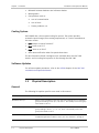
Purpose and Use
The DXC-100PSX N+1 Protection Switch provides automatic backup for failed
narrowband (D8E1T1) and/or broadband (DT3 or DE3) module sets in a DXC-100
Multiservice Access Node, whether used as a standalone or as part of a stack.
The backup is accomplished by providing a redundant (spare) module set within
the DXC-100 of identical type as the primary module(s) being protected. Both the
spare and primary modules are configured into protection groups, which are
monitored by the System Manager module (DSMC.2 or DXNM). When the DSMC.2
determines that there is a problem with one of the primary modules and a
switchover is required, it will configure the spare to match the defective primary
module and will then command the DXIP to transfer the network traffic to the
redundant module set, via interface relays. This design allows the link to resume
operation without user intervention, and with only a minimal amount of
downtime.
Note
The generic term SMC is used to refer to either type of System Manager module,
DSMC.2 or DXNM. The full designation is used when the information is applicable
only to a specific module type.
Main Features
The primary function of the DXC-100PSX N+1 Protection Switch is to allow a
DXC-100 operated in a stack or as standalone to carry redundant Narrowband
(D8E1T1) or Broadband (DT3 or DE3) module sets, which provides the user a
backup capability in the event that a Broadband or Narrowband module becomes
non-operational. With the DXC-100PSX in place, the non-operational module
should be switched to a backup module. This allows the system to reconfigure
links and continue operating with minimum down time and without any user
intervention.
The following conditions will cause a switchover from the primary to the standby
module:
DXC-100PSX
•
Front or rear card is not present
•
Channel card encounters system fatal errors
•
Channel card not receiving message from the SMC
Overview
1-1
Chapter 1 Overview
Installation and Operation Manual
•
Mismatch between hardware and software shadow
•
Missing cables
•
Card problems such as:
Loss of communication
Loss of clock
Framer problems, etc.
Cooling System
DXC-100PSX has a three-speed cooling fan system. The system provides
automatic speed change (auto-sensing temperature) or it can be controlled via
the menu screen.
•
Low: Always on unless forced off
•
Med: turns on at 97°F
•
High: turns on at 110°F
•
Auto alarm notification when fan speeds slow down.
The N+1 Protection Switch is designed to be mounted above the DXC-100
chassis, and its cooling fan improves air flow through the DXC-100.
Software Updates
For software update procedures, refer to the Utilities chapter of the DXC-100
Installation and Operation Manual.
1.2
Physical Description
General
The following list explains specific terms used in this manual.
Term
Meaning
Broadband Group 1
Refers to the broadband cards that have been established in a redundant
group and residing in slots 8, 9, 10, and 11. The standby card in this group
must reside in slot 11.
Broadband Group 2
Refers to the broadband cards that have been established in a redundant
group residing in slots 1, 2, 3, 4, 5, 6, and 7. The standby card in this
group must reside in slot 7.
Broadband Primary Card
This card resides in the protection switch and is used to back up a
broadband application module in slot 8, 9 or 10, and slots 1 through 6.
1-2
Physical Description
DXC-100PSX
Installation and Operation Manual
Chapter 1 Overview
Term
Meaning
Broadband Redundant Card
This card resides in the protection switch and is used to back up a
broadband application module; it must reside in slot 11 or 7.
Controller Card
Provides communications between the DXC-100 System Manager and the
protection switch.
N+1 Device Redundancy (NDR)
A redundant device is provided to replace a failed primary device in a
group.
N+1 Device Redundancy Group
(NDRG)
A collection of configured primary devices and a redundant device that will
be used for redundancy.
Narrowband Primary Card
This card resides in the protection switch and is used to back up a
narrowband application module in slots 2, 3, 4, 5, 6, 7, 8, 9, 10 or 11.
Narrowband Redundant Card
This card resides in the protection switch and is used to back up a
narrowband application module; it must reside in slot 1.
Primary Device
A device in a redundancy group that would normally carry traffic.
Primary Slots (DXC-100)
Cards plugged into these slots are considered active and on-line under
normal operation.
Primary Slots (Protection Switch) Holds interface cards for the cards plugged into the DXC-100 primary slots.
Protected Device
This is a primary device that will be replaced by a redundant device should
it fail within its redundancy group.
Redundant Device
One device in a redundancy group that has been configured to replace or
substitute for a failed primary device in the redundancy group.
Restore
An action that occurs when traffic is returned to the primary device that
was being protected in the redundancy group by a redundant device.
Standby Slots (DXC-100)
Cards plugged into these slots are considered inactive and off-line under
normal operation. They become active and go on-line when a card plugged
into the primary slot becomes non-operational.
Standby Slots (Protection
Switch)
Holds interface cards for the cards plugged into the DXC-100 standby
slots.
Switchover
An action that occurs when a redundant device replaces a primary device
that failed.
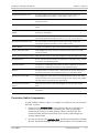
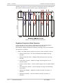
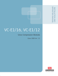
Protection Switch Components
The DXC-100PSX, shown in Figure 1-1 installed in its position over the protected
DXC-100, contains:
0
DXC-100PSX
•
Eleven slots for Interface Cards - these cards provide the functionality to
switch to the DXC-100 primary or redundant slot. They are physically
connected via primary or standby adapter cables to the DXC-100. The
Protection Switch network connections come into this card through the
Primary Adapter Cable.
•
One slot for the fail-safe Controller Card - provides communications between
the DXC-100 System Manager and the Protection Switch. The Controller Card
Physical Description
1-3
Chapter 1 Overview
Installation and Operation Manual
and DXC-100 System Manager (DSMC.2) or Expansion Node Manager (DXNM)
are connected via a DB9 serial interface cable.
•
Two slots for the DC Redundant Power Supply. The DC Power Supply has a
range of 43.2V DC to 52.8V DC. Terminal blocks are used for DC power input.
•
A fan assembly unit for auxiliary cooling.
DSTM-1/DOC-3
Figure 1-1. DXC-100PSX Protection Switch and DXC-100, Rear View
1-4
Physical Description
DXC-100PSX
Installation and Operation Manual
Chapter 1 Overview
Indicators
There is only one indicator on the DXC-100PSX; it is a READY indicator that
resides on the PSX Controller Module. See Table 1-1 for indicator states and
associated illumination criteria.
1
Table 1-1. DXC-100PSX Indicator (Controller Module)
Indicator
State
Description
READY
Flashing Green
Protection Switch is powered up and the PSX Controller is
communicating with the System Manager Module (DSMC.2) in the
DXC-100.
Flashing Red
PSX Controller is powered up, but not communicating with the
System Manager Module (DSMC.2) in the DXC-100.
OFF
Protection Switch is not powered up or PSX Controller is not
operational.
If the READY LED is alternately flashing between red and green, the PSX
Controller Module is downloading software to memory.
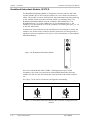
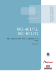
DC Power Supply Module, DPC/DC
The DC Power Supply Module is designed to take -48VDC input power and use it
to supply 24VDC for fan operation and 5VDC for digital logic and relay operation.
The input power passes through a 2 Amp, 250V, fast acting fuse (designated as
F1) and an inrush current limiter.
The DXC-100PSX can be configured with either a single DC Power Supply Module
or optionally two power supplies for redundant operation. Two front-accessible,
full-height power supply slots are provided in the DXC-100PSX chassis; a
minimum of one power supply is required per DXC-100PSX nest.
Thumbscrews are provided at the top and bottom of the faceplate to secure the
module in the chassis and to make an electrical connection to frame ground for
regulatory emission compliance. See Figure 1-2 for an illustration of a DC Power
Supply Module.
2
DXC-100PSX
Physical Description
1-5
Chapter 1 Overview
Installation and Operation Manual
DPS/DC
DC POWER
Figure 1-2. DC Power Supply Module
+
-
Each DC Power Supply Module has a single connector (with 3mm screw down
terminals) to interface to the -48VDC external power source(s). Terminal polarity
labeling is provided on the rear faceplate.
Note
This connector is identical to that utilized on the DXC-100 chassis DC power
input.
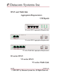
Protection Switch Controller Module, DNC
The PSX Controller Module is used to manage the N+1 Protection switch, as well
as connect it to the controlling DXC-100 resident System Manager (DSMC.2) or
DXC-100 Expansion Node Manager (DXNM) Rear Card. It also manages the
DXC-100PSX fan assembly and relay interface operations. The controller module
is fail-safe so that if it stops operating due to a fault (such as loss of power or its
removal), the DXC-100PSX resident latching relays will maintain their positions in
a non-disruptive manner.
Note
For the DXC-100 stack configuration, a DSMC.2 (DXNM) interface module must be
installed in each DXC-100 nest in order to connect the PSX Controller Module to
the DXC-100 nest.
The DXC-100PSX supports a single controller module that is installed in the
allocated slot; one controller module is required per nest. There is no provision
for redundancy of the PSX controller since the system itself is fail-safe in that
latching relays are employed. This means that the configuration prior to a
potential controller failure will be maintained.
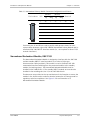
Thumbscrews are provided at the top and bottom of the faceplate to secure the
module in the chassis and to make an electrical connection to frame ground for
regulatory emission compliance. See Figure 1-3 for an illustration of the
Controller Module panel.
3
1-6
Physical Description
DXC-100PSX
Installation and Operation Manual
Chapter 1 Overview
DNC
READY
Figure 1-3. N+1 Protection Switch
Controller Module
A single bi-color (green/red) LED is provided to indicate whether the controller
module is powered and operating properly. See Table 1-1 for the indicator states
and associated illumination criteria.
4
The PSX Controller module directly interfaces the DXC-100 resident DSMC.2 or
DXNM module sets via a DB-9 (EIA-232) 38.4 kbps asynchronous serial data link.
See Table 1-2 for the connector configuration and associated pinouts.
5
Table 1-2. PSX Controller Module Connector Configuration and Pinouts
DB-9 Pin Locations
9
8
7
6
5
4
3
2
1
Pin
Signal
1
DXC-100PSX Reset (current source)
2
Data (to DXC-100PSX)
3
Data (from DXC-100PSX)
4
DXC-100PSX Present (current source)
5
Ground
6
DXC-100PSX Present (current sink - active low)
7
DXC-100PSX Reset (current sink - active low)
8
–
9
–
Narrowband Primary Module, D8E1T1/P
The Narrowband Primary Module is designed to interface with a DXC-100 resident
protected D8E1T1 interface module via the attached interconnection cable. This
module is used to facilitate DXC-100 commanded interface switching from the
protected module to the standby module (via latching relays). The Narrowband
Primary Module must be installed in DXC-100PSX slots 2 through 11 as part of a
Narrowband Protection Group. The protected D8E1T1 module set must be
installed in a matching slot (slots 2 through 11) in the DXC-100 chassis.
DXC-100PSX
Physical Description
1-7
Chapter 1 Overview
Installation and Operation Manual
Thumbscrews are provided at the top and bottom of the faceplate to secure the
module in the chassis and to make an electrical connection to frame ground for
regulatory emission compliance. See Figure 1-4 for an illustration of a
Narrowband Primary Module.
6
A single 50-pin (AMP 552725-1 telco-type) female receptacle is mounted on this
module and is used to directly interface the narrowband network facilities in
place of the identical DXC-100-resident D8E1T1 (primary) port interface, which is
now interfaced via the integrated "elephant trunk" cable assembly.
See Table 1-3 for the connector configuration and associated pinouts.
7
D8E1T1/P
Figure 1-4. Narrowband Primary Module
1-8
Physical Description
DXC-100PSX
Installation and Operation Manual
Chapter 1 Overview
Table 1-3. Narrowband Primary Module Connector Configuration and Pinouts
Pin Locations
Transmit
Receive
Tip
Ring
Tip
Ring
1
26
1
27
2
28
3
2
29
4
30
5
31
6
3
32
7
33
8
34
9
4
35
10
36
11
37
12
5
38
13
39
14
40
15
6
41
16
42
17
43
18
7
44
19
45
20
46
21
8
47
22
48
23
49
24
Link
Reserved
Connector pins 25 and 50 are used to provide cable present status for intersystem cables between a given DXC-100PSX Narrowband Primary Module and its
associated DXC-100 D8E1T1 interface module (i.e., not required for direct T1/E1
network interfaces).
Narrowband Redundant Module, D8E1T1/R
The Narrowband Redundant Module is designed to interface with the DXC-100
resident standby D8E1T1 interface module via a Telco-to-Telco type
interconnection cable (provided). This module is used to facilitate DXC-100
commanded interface switching from the protected module to the standby
module (via latching relays). The Narrowband Redundant Module must be
installed in DXC-100PSX slot 1. The standby D8E1T1 module set must also be
installed in the matching slot (slot 1) in the DXC-100 chassis.
Thumbscrews are provided at the top and bottom of the faceplate to secure the
module in the chassis and to make an electrical connection to frame ground for
regulatory emission compliance. See Figure 1-5 for an illustration of a
Narrowband Redundant Module.
8
DXC-100PSX
Physical Description
1-9
Chapter 1 Overview
Installation and Operation Manual
D8E1T1/R
Figure 1-5. Narrowband Redundant
Module
A single 50-pin (AMP 552725-1 telco-type) female receptacle is mounted on this
interface module and is used to directly interface the identical DXC-100-resident
D8E1T1 (redundant) port interface (i.e., there is no direct network interface for
redundant modules). See Table 1-4 for the connector configuration and
associated pinouts.
9
Table 1-4. Narrowband Redundant Module Connector Configuration and Pinouts
Pin Locations
Transmit
Receive
Tip
Ring
Tip
Ring
1
26
1
27
2
28
3
2
29
4
30
5
31
6
3
32
7
33
8
34
9
4
35
10
36
11
37
12
5
38
13
39
14
40
15
6
41
16
42
17
43
18
7
44
19
45
20
46
21
8
47
22
48
23
49
24
Link
Reserved
Connector pins 25 and 50 are used to provide cable present status for intersystem cables between a given DXC-100PSX Narrowband Redundant Module and
its associated DXC-100 D8E1T1 interface module.
Broadband Primary Module, DE3T3/P
The Broadband Primary Module is designed to interface with a DXC-100-resident
protected DT3 or DE3 interface module via a set of BNC interconnection cables.
This module is used to facilitate DXC-100 commanded interface switching from
the protected module to the standby module (via latching relays). The Broadband
Primary Module must be installed in DXC-100PSX slots 1 through 6 for Broadband
1-10
Physical Description
DXC-100PSX
Installation and Operation Manual
Chapter 1 Overview
Group 2 or in DXC-100PSX slots 8 through 10 for Broadband Group 1. The
protected DT3 or DE3 module set must be installed in a matching slot (slots 1 to
6 or 8 to10) in the DXC-100 chassis.
Thumbscrews are provided at the top and bottom of the faceplate to secure the
module in the chassis and to make an electrical connection to frame ground for
regulatory emission compliance. See Figure 1-6 for an illustration of a Broadband
Primary Module.
1
D/E3T3/P
IN
RX
TX
Figure 1-6. Broadband Primary Module
OUT
TX
RX
Two sets of individual BNC (AMP 415085-1 locking bayonet-type) female
receptacles (four total) are mounted on the Broadband Primary interface module
with the IN pair interfacing the broadband facility and the OUT pair interfacing
the associated DXC-100-resident module set.
See Figure 1-7 for the IN and OUT connector configuration and labeling.
1
Broadband Primary IN Connectors (Top Pair)
Receive (from Network)
Transmit (to Network)
RX
TX
Shield Ground
Shield Ground
Broadband Primary OUT Connectors (Bottom Pair)
Transmit (to DXC-100)
TX
Shield Ground
Receive (from DXC-100)
RX
Shield Ground
Figure 1-7. Broadband Primary Module BNC Connector Configuration and Pinouts
DXC-100PSX
Physical Description
1-11
Chapter 1 Overview
Installation and Operation Manual
Broadband Redundant Module, DE3T3/R
The Broadband Redundant Module is designed to interface with the DXC-100resident standby DT3 or DE3 interface module via a set of BNC interconnection
cables. This module is used to facilitate DXC-100-commanded interface switching
to the standby module from the protected module (via latching relays). The
Broadband Redundant Module must be installed in DXC-100PSX slot 7 for
Broadband Group 2, or in DXC-100PSX slot 11 for Broadband Group 1. The
standby DT3 or DE3 module set must be installed in a matching slot (slot 7 or 11)
in the DXC-100 chassis.
Thumbscrews are provided at the top and bottom of the faceplate to secure the
module in the chassis and to make an electrical connection to frame ground for
regulatory emission compliance. See Figure 1-8 for an illustration of a Broadband
Redundant Module.
1
D/E3T3/R
OUT
TX
RX
Figure 1-8. Broadband Redundant Module
One set of individual BNC (AMP 415085-1 locking bayonet-type) female
receptacles (two total) are mounted on the Broadband Redundant interface
module with the OUT pair interfacing the associated DXC-100 resident module
set.
See Figure 1-9 for the OUT connector configuration and labeling.
1
Broadband Redundant OUT Connectors
Transmit (to DXC-100)
TX
Shield Ground
Receive (from DXC-100)
RX
Shield Ground
Figure 1-9. Broadband Redundant Module BNC Connector Configuration and
Pinouts
1-12
Physical Description
DXC-100PSX
Installation and Operation Manual
Chapter 1 Overview
Fan Assembly
The field-replaceable exhaust fan assembly removes the heated air from the
DXC-100PSX enclosure as well as the associated DXC-100 nest. Figure 1-10
shows the front-mounted fan assembly (containing three fan units) with the
front cover removed.
1
Figure 1-10. Fan Assembly (without Front Cover)
1.3
Functional Description
Broadband Redundancy
Broadband Normal Operation
During normal (non-fault) conditions, broadband user traffic to and from the
network passes through the latching relays within the DXC-100PSX primary
interface module which is directly attached to the link. If it is not already
protecting another DXC-100 broadband module set within one of the two user
defined broadband protection groups (BB1 supporting up to 3+1 or BB2
supporting up to 6+1 module redundancy), the redundant broadband module set
will be performing self-test diagnostics via the looped back path within the
DXC-100PSX redundant interface module.
In the event that a fault or failure is detected within the standby module set, that
given broadband redundancy group will be disabled for the duration of the fault
DXC-100PSX
Functional Description
1-13
Chapter 1 Overview
Installation and Operation Manual
condition. See Figure 1-11 for an overview of the normal operation utilizing both
BB1 (shown in black) and BB2 (shown in gray) redundancy groups.
DXC-100
1
Figure 1-11. Broadband Normal Operation
Broadband Protection Mode Operation
In the event that a fault or failure is detected within a DXC-100 broadband
primary module set, a system-level alarm will be issued and the
DXC-100/DXC-100PSX broadband redundancy switching process will commence.
This process is as follows:
1. DSMC.2 (or DXNM) detects module-level fault or failure condition, such as:
1-14
Missing System Clock – DXC-100 16.384MHz clock signal not being
received
Missing Frame Sync Pulse – Midplane TDM synchronization not being
received
Invalid Fabric Timeslot – Module no longer interfacing fabric due to
timeslot conflict
Incorrect Framer Values – Framer resident registers do not match shadow
copy
Lost Supervisory Channel – System manager no longer communicating
with module
Missing Front Module – Application module removed, lost power, or
defective
Missing Rear Module – Interface module removed, lost power, or
defective.
Functional Description
DXC-100PSX
Installation and Operation Manual
Chapter 1 Overview
2. Redundant broadband module set (if in standby mode) receives configuration
and crossconnect map information for the defective module from the
DXC-100 system manager.
3. PSX controller module receives command from the DXC-100 system manager
to transfer the broadband link (including all embedded T1/E1 links) to the
redundant module in place of the failed broadband module set.
4. Redundant module will synchronize with the link and user traffic will be
re-established.
See Figure 1-12 for an overview of the protection operation where a fault is
detected with the BB2 related DXC-100 module set located in slot 4 (BB1 group
unaffected).
1
Once the original fault has been cleared or the defective module(s) replaced, the
operator can command the DXC-100/PSX to restore the normal path (i.e.,
revertive restoration is not an automatic process by design).
DXC-100
Due to the N+1 nature of this module sparing scheme (versus 1+1 dedicated
redundancy) this switchover requires a few seconds to complete in a worse case
situation. The only situation that may go beyond this normal range is if the
broadband module set ceases communications to the system manager via the
supervisor channel. The capability to perform a commanded switchover for
maintenance or upgrade purposes in less than 50 milliseconds is available.
Figure 1-12. Broadband Protection Operation
See Table 1-5 for a summary of typical total switchover times for different
scenarios as measured on external test sets (i.e., total disruption time observed
for given switchover criteria).
1
DXC-100PSX
Functional Description
1-15
Chapter 1 Overview
Installation and Operation Manual
Table 1-5. Broadband Switchover Times
Error Type
Switchover Time
Missing System Clock
5 seconds
Missing Frame Sync Pulse
5 seconds
Invalid Backplane Timeslot Management
5 seconds
Incorrect Framer Values
1 second
Lost Communications with System Manager
60 seconds
Missing Application Module (Front Card)
20 seconds
Missing Interface Module (Rear Card)
5 seconds
Commanded Switchover
<50 milliseconds
Narrowband Redundancy
Narrowband Normal Operation
During normal (non-fault) conditions, narrowband user traffic to and from the
network passes through the latching relays within the DXC-100PSX primary
interface module which directly attaches to the link. If it is not already protecting
another DXC-100 narrowband (D8E1T1) module set within the user defined
narrowband protection, the redundant narrowband (D8E1T1) module set will be
performing self-tests via the looped back path within the DXC-100PSX redundant
interface module. In the event that a fault or failure is detected within the
standby module set and narrowband redundancy will be disabled for the duration
of the fault condition. See Figure 1-13 for an overview of normal operation using
the Narrowband Redundancy Group.
1
1-16
Functional Description
DXC-100PSX
Chapter 1 Overview
DXC-100
Installation and Operation Manual
Figure 1-13. Narrowband Normal Operation
Narrowband Protection Operation
In the event that a fault or failure is detected within a primary DXC-100
narrowband module set, a system-level alarm will be issued and the
DXC-100/DXC-100PSX narrowband redundancy switching process will commence.
This process is as follows:
1. DSMC.2 (or DXNM) detects module-level fault or failure condition, such as:
DXC-100PSX
Missing System Clock - DXC-100 16.384MHz clock signal not being
received
Missing Frame Sync Pulse - Midplane TDM synchronization not being
received
Invalid Fabric Timeslot - Module no longer interfacing fabric due to
timeslot conflict
Incorrect Framer Values - Framer resident registers do not match shadow
copy
Lost Communications - System manager no longer communicating with
module
Missing Front Module - Application module removed, lost power or
defective
Missing Rear Module - Interface module removed, lost power or defective
Missing DXC-100/PSX Cable - D8E1T1 cable to DXC-100PSX primary
interface module removed
Functional Description
1-17
Chapter 1 Overview
Installation and Operation Manual
2. Redundant narrowband (D8E1T1) module set (if in standby mode) receives
configuration and cross-connect map information for the defective module
from the DXC-100 system manager.
3. PSX controller module receives command from the DXC-100 system manager
to transfer all eight links to the redundant module in place of the failed
D8E1T1 module set.
4. Redundant module will synchronize with the links and user traffic will be
reestablished.
See Figure 1-14 for an overview of the protection operation using the
Narrowband Redundancy Group.
1
DXC-100
Once the original fault has been cleared or the defective module(s) replaced, the
operator can command the DXC-100/PSX to restore the normal path (i.e.,
revertive restoration is not an automatic process by design).
Figure 1-14. Narrowband Protection Operation
1-18
Functional Description
DXC-100PSX
Installation and Operation Manual
Chapter 1 Overview
Table 1-6. Narrowband Switchover Times
Error Type
Switchover Time
Missing System Clock
~5 seconds
Missing Frame Sync Pulse
~5 seconds
Invalid Backplane Timeslot Management
~5 seconds
Incorrect Framer Values
~1 second
Lost communications with System Manager
~60 seconds
Missing Application Module (Front Card)
~1 second
Missing Interface Module (Rear Card)
~5 seconds
Missing DXC-100/DXC-100PSX Cable
~1 second
Commanded Switchover
<50 milliseconds
1.4
General
Technical Specifications
Configuration
• Can be configured with a standalone DXC-100
chassis
• Can be configured in a DXC-100 stack node
Certifications
FCC Part 15 and Part 68, IC, UL1950, IC CSO3,
IC-003, EN60950, EN55022, EN50082, NEB/L3,
CTR 12/13, CB Scheme
Power Supply
-48VDC ±10%, max. 48W
Slots
11 primary/redundant module slots, plus 2 power
supply slots and 1 controller slot
Dimensions
133 mm (5.25”) H (3 RU) x 432 mm (17”) W x
356 mm (14”)
Weight
12.5 kg (27.5 lbs) fully loaded
Mounting
Rack mount (19" or 23") Flush or Center Mount
Input Power
-48 VDC ±10%, Max. 48 Watts
Fuse
F1 (in DC Power Supply Module): 2 Amp, 125V,
Fast Acting
Environment
Temperature: 0° (32°F) to 50°C (122°F)
Humidity: 0% to 90% (non-condensing)
DXC-100PSX
Technical Specifications
1-19
Chapter 1 Overview
DC Power Supply
Module
PSX Controller
Module
Narrowband
Primary Module,
D8E1T1/P
Installation and Operation Manual
Physical Dimensions
133 mm H (5.25”) x 235 mm (9.25”) D x 53 mm
(2”) W
Functionality
Provides DC power for DXC-100PSX
Nominal Input Voltage
-48 VDC
Connector
3-position panel-mounted header (Phoenix
07-07-25-1) and terminal strip/plug (Phoenix
17-57-02-2)
Fuse
F1 (on printed circuit board): 2A, 125V,
fast-acting
Physical Dimensions
133 mm (5.25”) H x 220 mm D x 26 mm (1”) W
Functionality
Control
Nominal Input Voltage
Serial asynchronous data
Connector
DB9 serial connector on faceplate
Physical Dimensions
133mm H x 222mm D x 26mm W
Functionality
Narrowband redundancy (T1 or E1)
Nominal Input Voltage
T1 (100Ω) or E1 (120Ω)
Connectors
• 50-pin, RJ48F connector on faceplate: T1
(100Ω) or E1 (120Ω)
• 50-pin, RJ48M connector on attached cable T1
(100Ω) or E1 (120Ω)
Narrowband
Physical Dimensions
Redundant
Module, D8E1T1/R Functionality
Broadband
Primary Module,
DE3T3/P
1-20
133mm H × 222mm D × 26mm W
Narrowband Redundancy for D8E1T1 Module
Nominal Input Voltage
T1 (100Ω) or E1 (120Ω)
Connector
50-pin, RJ48F connector on faceplate: T1 (100Ω)
or E1 (120Ω)
Physical Dimensions
133 mm H (5.25”) x 235 mm (9.25”) D x 26 mm
(1”) W
Functionality
Broadband redundancy for DT3 or DE3 modules
Nominal Input Voltage
T3, STS1, or DE3
Connector
4 female BNC (75Ω) on faceplate - 1 transmit, 1
receive
Technical Specifications
DXC-100PSX
Installation and Operation Manual
Broadband
Redundant
Module, DE3T3/R
Fan Assembly
DXC-100PSX
Chapter 1 Overview
Physical Dimensions
133 mm H (5.25”) x 235 mm (9.25”) D x 26 mm
(1”) W
Functionality
Broadband redundancy for DT3 or DE3 modules
Nominal Input Voltage
DT3 or DE3
Connector
2 female BNC (75Ω) on faceplate - 2 transmit, 2
receive
Functionality
Removes heated air from DXC-100PSX and
DXC-100 units
Maximum Airflow
100 cfm per fan (3 fans)
Noise Level
45 dBA per fan (3 fans)
Technical Specifications
1-21
Chapter 1 Overview
1-22
Technical Specifications
Installation and Operation Manual
DXC-100PSX
Chapter 2
Module Installation and
Operation
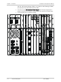
2.1
Installing and Connecting the Protection Switch
This section will guide you through installing the DXC-100PSX N+1 Protection
Switch, installing modules, and configuring Network Redundancy.
DPS/DC
DPS/DC
DE3T3/R
OUT
DC POWER
TX
DE3T3/P
IN
D8E1T1/P
D8E1T1/R
RX
DNC
READY
DC POWER
RX
+
-
TX
+
OUT
TX
RX
Figure 2-1. N+1 Protection Switch (Rear View)
Ensure that you have 3RU (5.25"/133mm) of empty rack space above the
DXC-100 unit in which to install the N+1 Protection Switch.
1. Securely mount the N+1 Protection Switch in the equipment rack, directly
above the DXC-100.
2. Connect the DB9 male-to-male serial interface cable to the DB9 connector on
the PSX Controller module. See Figure 1-3 for connector location.
DXC-100PSX
Installing and Connecting the Protection Switch
2-1
Chapter 2 Module Installation and Operation
Installation and Operation Manual
3. Connect the opposite end to the DB9 connector located on the DSMC.2 rear
interface module, marked PROTECT SWT.
4. Install the primary and redundant interface modules.
The DXC-100PSX Primary and Redundant Interface Module components are
sensitive to electrostatic discharge. When handling these modules, wear an
ESD
anti-static wrist strap connected to frame ground to prevent damage to circuits
Caution from electrostatic discharge.
Note
The Primary and Redundant Interface modules have a one-to-one
correspondence with the DXC-100 Interface modules; see Table 2-1.
0
Table 2-1. One-to-One Correspondence
Slot
Module
Slot 1
Narrowband Redundant Card, D8E1T1/R
Slots 2 to 11
Narrowband Primary Card, D8E1T1/P
Slot 11
Broadband Redundant Card, DE3T3/R
Slots 8 to 10
Broadband Primary Card, DE3T3/P
Slot 7
Broadband Redundant Card, DE3T3/R
Slots 1 to 6
Broadband Primary Card, DE3T3/P
Narrowband Redundancy Connections
1. Connect the 50-pin cable from the network to the 50-pin connector on the
DXC-100PSX Narrowband Primary module.
5. Connect the 50-pin cable from the Narrowband Primary module to the
corresponding 50-pin connector on the DXC-100 Narrowband (D8E1T1) rear
interface module.
6. Attach the 50-pin male-to-male cable (CBL-100PSX-D8E1T1) from the
Narrowband Redundant module to the Standby slot 1 on the DXC-100.
Figure 2-2 illustrates a DXC-100PSX connection for Narrowband Redundancy.
1
2-2
Installing and Connecting the Protection Switch
DXC-100PSX
Chapter 2 Module Installation and Operation
DXC-100
Installation and Operation Manual
Figure 2-2. DXC-100PSX Narrowband Cable Installation
Note
In the above figure, slots 3 and 5 contain Narrowband primary interface modules,
and slot 1 contains the Narrowband Group backup module. The numbers on the
cables correspond to the steps in the Narrowband Connection procedure above.
Note
To power up, refer to Connecting N+1 Protection Switch DC Power (-48VDC) on
page 2-4.
2
3
Broadband Redundancy Connections
1. Connect the RX BNC cable from the network to the "IN" RX jack on the
DXC-100PSX Broadband Primary module and the TX BNC cable to the network
to the "IN" TX jack.
2. Connect one of the BNC attachment cables (CBL-100PSX-DE3T3) between the
DXC-100PSX Primary "OUT" TX and the RX port of the corresponding
broadband interface module in the DXC-100.
3. Connect another BNC attachment cable (CBL-100PSX-DE3T3) between the
DXC-100PSX Primary "OUT" RX and the TX port of the corresponding
broadband interface module in the DXC-100.
4. Connect another BNC cable (CBL-100PSX-DE3T3) between the RX port of the
DXC-100PSX Broadband Redundant module and the TX port of the
corresponding backup broadband interface module in the DXC-100.
DXC-100PSX
Installing and Connecting the Protection Switch
2-3
Chapter 2 Module Installation and Operation
Installation and Operation Manual
5. Connect another BNC cable (CBL-100PSX-DE3T3) between the TX port of the
DXC-100PSX Broadband Redundant module and the RX port of the
corresponding backup broadband interface module in the DXC-100.
Figure 2-3 illustrates a DXC-100PSX connection for Broadband Redundancy.
DXC-100
4
Figure 2-3. DXC-100PSX Broadband Cable Installation
Note
In the above figure, slot 9 contains a Broadband Group 1 primary interface
module, and slot 11 contains the Broadband Group 1 backup module. Slots 2 and
4 contain Broadband Group 2 primary interface modules, and slot 7 contains the
Broadband Group 2 backup module. The numbers on the cables correspond to
the steps in the Broadband Connection procedure on the previous page.
Note
To power up, refer to Connecting N+1 Protection Switch DC Power (-48VDC)
below.
5
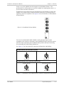
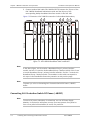
Connecting N+1 Protection Switch DC Power (-48VDC)
Note
To ensure DC power redundancy is maintained, use two DC Power Supply
Modules, in conjunction with power sources from two separate fuse panels or
from a fuse panel with redundant (A and B) fuse positions.
2-4
Installing and Connecting the Protection Switch
DXC-100PSX
Installation and Operation Manual
Chapter 2 Module Installation and Operation
1. Mount the unit above a DXC-100 unit in a rack as specified previously.
2. Shut off -48VDC power to the DC supply leads.
3. Strip the insulation back approximately 5/16 inch (8 mm) from the end of
each lead.
4. Note the positions of earth, negative and positive on the DC power plug
(designations are on the DC Power Supply Module faceplate).
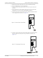
5. Remove the DC power terminal block from the mating receptacle on the DC
Power Supply Module faceplate (see Figure 2-4).
6
DPS/DC
DC POWER
Figure 2-4. Remove Power Terminal Block
+
-
6. Insert the “earth” lead into the earth terminal clamp on the power terminal
block and tighten the clamp screw using a small flat screwdriver (see
Figure 2-5).
7
DPS/DC
DC POWER
Figure 2-5. Connecting DC Power Leads
DXC-100PSX
+
-
Installing and Connecting the Protection Switch
2-5
Chapter 2 Module Installation and Operation
Installation and Operation Manual
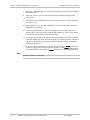
7. Insert the “-48 volt supply” wire into the negative terminal clamp and tighten
the clamp screw.
8. Insert the “return” wire into the positive terminal clamp and tighten the
clamp screw.
9. Insert the power terminal block into the mating receptacle on the rear panel
(see Figure 2-5).
8
10. Repeat Steps 2 to 9 if the DXC-100PSX has a second (redundant) DC Power
Supply Module installed.
11. To minimize disturbance to the wires through casual contact, secure the
power cables to the rack frame using multiple cable ties. The first tie should
be located within 6 inches of the terminal block.
12. Power up both the DXC-100 and N+1 Protection Switch. The LED on the PSX
Controller Module will flash as the unit powers up, loads software, and runs a
self-test. This will take a few minutes, depending upon how many modules
have been configured.
13. Once the system is powered up, you should see a flashing Green READY LED
on the N+1 Protection Switch Controller module; a solid Green READY LED on
the online DSMC.2; and a flashing Green READY LED on the Standby DSMC.2.
Note
Ignore any alarms at this point.
2-6
Installing and Connecting the Protection Switch
DXC-100PSX
Chapter 3
Configuration Instructions
3.1
Verifying Protection Switch Installation
To ensure that the Protection Switch has been properly installed, verify the Card
Status is Ok and the Switch State’s condition is Normal.
Note
³
For detailed craft terminal operating instructions refer to the DXC-100 Installation
and Operation Manual.
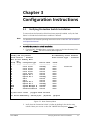
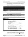
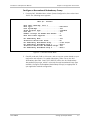
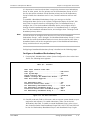
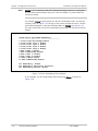
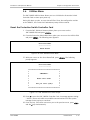
To verify the protection switch installation:
1. From the DXC-100 Main Menu, move your cursor to the Nest Summary field
and press <Enter> The Nest Summary Menu appears:
Standby SMC not present
Alarm Contacts..: Enabled
Nest #1 Slot Summary Menu
N+1
Slot# Group Configured Type
----- ----- --------------01
Octal T1/E1
02
Octal T1/E1
03
Octal T1/E1
04
Octal T1/E1
05
Octal T1/E1
06
Hybrid DS-3
07
Hybrid DS-3
08
STS-1
09
STS-1
10
Hybrid DS-3
11
Hybrid DS-3
SMCA
System Manager A
SMCB
System Manager B
PSX
ProtectionSwitch
[C]lear error counts
N+1 Redundancy State: Enabled
Alarm Contact Type..: Standard
Device State
-----------Standby
Online
Online
Online
Online
Online
Standby
Online
Online
Online
Standby
Standby
Online
Online
Alarm
----None
None
None
None
None
None
None
None
None
None
None
None
None
None
Clock Src
[T]oggle Alarm Contacts
N+1 Device Redundancy: Switch[O]ver
[R]estore
[E]xpose
Figure 3-1. Nest Summary Menu
2. Verify that the Protection Switch is Online by looking in the device state
column. Move your cursor to the DXC-100PSX field and press <Enter>. The
DXC-100PSX
Verifying Protection Switch Installation
3-1
Chapter 3 Configuration Instructions
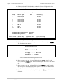
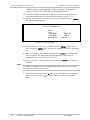
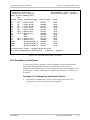
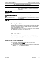
Installation and Operation Manual
Protection Switch Status Menu appears: it should look similar to the one
shown in Figure 3-2.
0
Status Menu
----------Slot# Card Type
Card Status
Switch State
Switch Status
---------------------------------------------------------------------------01
Narrowband Redundant
Ok
Normal
Ok
02
Narrowband Primary
Ok
Normal
Ok
03
Narrowband Primary
Ok
Normal
Ok
04
Narrowband Primary
Ok
Normal
Ok
05
Narrowband Primary
Ok
Normal
Ok
06
Broadband '2' Primary
Ok
Normal
Ok
07
Broadband '2' Redundant Ok
Normal
Ok
08
Broadband '1' Primary
Cable Missing Normal
Ok
09
Broadband '1' Primary
Ok
Normal
Ok
10
Broadband '1' Primary
Ok
Normal
Ok
11
Broadband '1' Redundant Ok
Normal
Ok
Power Supply A Status.: Ok
Fan Maintenance: Auto
Power Supply B Status.: Fault
Fan Speed......: Low
Chassis Temperature...: 85 F/29 C
Fan #01: Ok
Fan #02: Ok
Fan #03: Ok
Figure 3-2. Protection Switch Status Menu
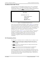
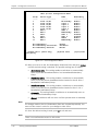
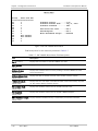
To expose additional information about the Protection Switch, go back to the
Nest Summary Menu, and at the DXC-100PSX field, press the E key. The resulting
screen should look similar to the one shown in Figure 3-3.
1
Protection Slot Information
----------------------------------------------Device........: Online
Psx Controller: Rev #0
Chassis.......: Undetermined
PSX Interface Card Alarms
01=None
02=None
03=None
07=None
08=None
09=None
04=None
10=None
----Major Alarms--Power Supply A: Ok
Power Supply B: Ok
Fan 1.........: Ok
Fan 2.........: Ok
Fan 3.........: Ok
05=None
11=None
06=None
Figure 3-3. Protection Switch Slot Information Display
The screen above shows the Protection Switch is online, and operating with the
Rev. 0 Controller Module. In this case, the chassis is ‘Undetermined’ because a
3-2
Verifying Protection Switch Installation
DXC-100PSX
Installation and Operation Manual
Chapter 3 Configuration Instructions
Rev. 0 Controller Module cannot determine the chassis type. In order to enable a
second broadband group, go to the Nest Profile Menu, which is displayed on the
following page. The information contained on the Protection Slot Information
Display is listed in Table 3-1.
2
Table 3-1. Protection Slot Information Display Field Descriptions
Field
Description
Device: (display field)
Displays the state of the DXC-100PSX as Online or Offline.
Psx Controller: (display field)
Displays the revision level of the PSX Controller Module.
Chassis: (display field)
Displays the type of chassis as DXC-100PSX.
Power Supply A or B:
(display field)
Displays the status of Power Supply A or B as one of the following:
•
Ok
•
Fault
Table 3-2. Protection Slot Information Display Field Descriptions
Field
Description
Fan 1, 2, or 3: (display field)
Displays the status of Fan 1, 2, or 3 as one of the following:
DXC-100PSX Interface Card
Alarms: (display field)
•
Ok – Fan is operating properly.
•
Fault – Fan has been shut off, or is otherwise inoperative.
Displays the status of each of the 11 slots in the DXC-100PSX.
Nest #1 : Profile
Nest name: Node Mgr. Unit I
Nest type:.............................:
Dual System Mgr........................:
Alarm Contacts Type....................:
Dual XCC...............................:
Number of Rings for Modem Auto-Answer..:
Nest Dual Power Supplies...............:
DXC-100
No
Standard
Yes
2
No
N+1 Redundancy Nest....................:
Protection Switch Dual Power...........:
N+1 Redundancy Narrowband Group........:
N+1 Redundancy Broadband Group 1.......:
Protection Switch Dual Broadband Groups:
N+1 Redundancy Broadband Group 2.......:
Yes
No
Octal T1/E1
HDS-3
Yes
HDS-3
Figure 3-4. The Nest Profile Menu
Carefully read each field on this menu, and set up your system based on your
equipment and software. If you have redundancy, select Yes on the N+1
Redundancy Node field. If you want to enable a second broadband group, select
DXC-100PSX
Verifying Protection Switch Installation
3-3
Chapter 3 Configuration Instructions
Installation and Operation Manual
Yes at the Protection Switch Dual Broadband Groups field. A new field, N+1
Redundancy Broadband Group 2, will appear. Establish which broadband devices
you want to include for Broadband Group 1 and Broadband Group 2.
If you have a Rev 0 Controller Module and the DXC-100PSX 2.3 software, you will
need to specify DXC-100PSX chassis in order for your system to support the
second broadband bus. Now, go back to the Nest Summary Menu. At the
Protection Switch field, press E to expose the Protection Switch slot information.
The Chassis field will show ‘Determined’ as long as you selected DXC-100PSX.
3.2
Setting Up a Redundancy Group
Each primary card contains its own configuration file; the redundant card contains
the configuration files downloaded from the card it will protect. The make up of a
Redundancy Group is user-configurable. Currently, the DXC-100 implements two
types of Redundancy Groups:
•
Narrowband Redundancy Group (and displayed in the menus as Nb) for
D8E1T1 modules in the node
•
Broadband Redundancy Group (and displayed in the menus as Bb-1 or Bb-2)
for DT3 or DE3 modules in the node.
Figure 3-5. Network Device Redundancy Groups
3-4
Setting Up a Redundancy Group
DXC-100PSX
Installation and Operation Manual
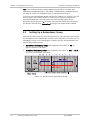
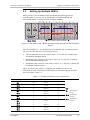
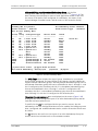
3.3
Chapter 3 Configuration Instructions
Setting Up Multiple NDRGs
While portions of the broadband and narrowband redundancy groups are
mutually exclusive, you can set up combinations of both broadband and
narrowband NDRGs, as well as multiple broadband NDRGs.
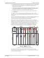
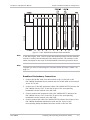
Figure 3-6. Rear View of DXC-100PSX showing possible Narrowband and Broadband
NDRGs
Up to three NDRGs (i.e., any combination of broadband and narrowband) can be
set up in the DXC-100 nest, see illustration above:
•
The narrowband devices can reside in slots 1 to 11, with slot 1 holding the
narrowband redundant device
•
Broadband group 1 devices can reside in slots 8 to 11, with slot 11 holding
the broadband redundant device
•
Broadband group 2 devices must reside in slots 1 to 7, with slot 7 holding the
broadband redundant device.
Again, all primary slots must be configured and enabled in order for the
switchover to occur. The allowed combinations of redundancy groups and their
slots are listed in Table 3-3.
3
Table 3-3. Possible Redundancy Group Combinations
Redundancy Group
Primary Slots
Primary Slot(s)
Standby Slot
Nb
10
2 to 11
1
Bb-2
6
1 to 6
7
Bb-1
3
8 to 10
11
Key:
Nb
Bb-1
6
3
2 to 7
8 to 10
1
11
Nb
Nb
Bb-2
4
1
2 to 5
6
1
7
Nb
Bb-2
Bb-1
4
1
3
2 to 5
6
8 to 10
1
7
11
Bb-2
Bb-1
6
3
1 to 6
8 to 10
7
11
DXC-100PSX
Narrowband
Group
Bb-2 Broadband
Group 2
Bb-1 Broadband
Group 1
Setting Up Multiple NDRGs
3-5
Chapter 3 Configuration Instructions
Installation and Operation Manual
Note
If a primary device in an Redundancy Group is being protected by a redundant
device, do not remove it from the group if a switchover has occurred.
Setting up a Narrowband Redundancy Group
A Narrowband Redundancy Group can contain up to eleven configured
narrowband devices. These devices reside in slots 1 through 11. It is not
necessary to have all narrowband devices in the nest be part of the Narrowband
Redundancy Group. Narrowband devices not configured as part of the
Redundancy Group will not be part of the Redundancy Group by default. You
must actually configure the device to be part of the Redundancy Group.
The Narrowband Redundancy Group can contain only one redundant device,
which must reside in Slot 1. If the redundant device is not in Slot 1, or has not
been configured as a part of the Redundancy Group or enabled, then the
Redundancy Group switchover will not occur.
It is important to note here that there is no priority structure to an Redundancy
Group. In other words, the first primary card in the Redundancy Group to fail is
the one that will be switched. Should another primary card in the Redundancy
Group fail while the redundant card is in use, another switchover will not take
place.
To establish a Narrowband Redundancy Group, you must go to the Slot
Configuration Menu. Refer to the System Configuration chapter in the DXC-100
User Guide for specific details on configuring a slot. Configure Slot 1 for the
narrowband redundant device; and configure slots 2 through 11 with narrowband
primary devices.
Note
You do not have to configure every slot in the DXC-100 nest with narrowband
devices, but note that any device other than a narrowband device will not be
recognized as part of that Redundancy Group, and therefore is not protected.
Configuring a Narrowband Redundancy Group is detailed on the following pages.
3-6
Setting Up Multiple NDRGs
DXC-100PSX
Installation and Operation Manual
Chapter 3 Configuration Instructions
Configure a Narrowband Redundancy Group
1. From the DXC-100 Main Menu, select System Configuration, then select Nest
Profile. The following menu appears:
Nest #1 : Profile
Nest name: Node Mgr. Unit I
Nest type:.............................:
Dual System Mgr........................:
Alarm Contacts Type....................:
Dual XCC...............................:
Number of Rings for Modem Auto-Answer..:
Nest Dual Power Supplies...............:
DXC-10011
Yes
Standard
Yes
2
No
N+1 Redundancy Nest....................:
Protection Switch Dual Power...........:
N+1 Redundancy Narrowband Group........:
N+1 Redundancy Broadband Group 1.......:
Protection Switch Dual Broadband Groups:
N+1 Redundancy Broadband Group 2.......:
Yes
No
Octal T1/E1
HDS-3
Yes
HDS-3
Figure 3-7. The Nest Profile Menu
3. Carefully read each field on this menu, and set up your system based on your
equipment and software. To enable redundancy, select Yes on the N+1
Redundancy Nest field. Octal T1/E1 (D8E1T1) will be the N+1 Redundancy
Narrowband Group type, which is currently the only Narrowband Group type
available. Configure the Broadband Redundancy Group(s) as appropriate to
your application module configuration.
DXC-100PSX
Setting Up Multiple NDRGs
3-7
Chapter 3 Configuration Instructions
Installation and Operation Manual
4. Go back to the DXC-100 Main Menu and select System Configuration, then
select Slot Configuration. The following menu appears:
Nest #1 Slot Configuration Menu
Slot#
----1
2
3
4
5
6
7
8
9
10
11
Device Type
---------------Octal T1/E1
Octal T1/E1
Octal T1/E1
Octal T1/E1
Octal T1/E1
HDS-3
HDS-3
STS1
STS1
HDS-3
HDS-3
N+1 Redundancy Switchover:
N+1 Redundancy Restore:
Change Card = [Enter key]
Name
------
Redundancy
-----------Disable
Disable
Disable
Disable
Disable
Disable
Disable
Disable
Disable
Disable
Disable
Automatic
Manual
[D]elete Card
[P]ort/Link Cfg
Figure 3-8. Slot Configuration Menu
5. Position the cursor next to the slot you want to configure and press <Enter>.
The following menu appears:
Slot Configuration
Nest............: 1
Slot............: 1
Slot Name.......: New York
Card Type.......: Octal T1-E1
Redundancy...: Disable
Figure 3-9. Individual Slot Configuration Screen
6. Move your cursor to the Slot name field and press <Enter>, type in a slot
name, and press <Enter> again. In the above example, New York is the named
slot.
7. Move your cursor to the Card type field and press <Enter> to scroll through
the card options until the desired card appears. In the case of a Narrowband
Group, select Octal T1/E1 (D8E1T1).
8. Move your cursor to the Redundancy field and press <Enter> until Enable is
displayed.
3-8
Setting Up Multiple NDRGs
DXC-100PSX
Installation and Operation Manual
Note
Chapter 3 Configuration Instructions
To enable redundancy for the Narrowband Redundancy Group you must have
selected Octal T1/E1 as the card type.
9. To exit and save changes, press X. When prompted: “Update Configuration?
Are you sure? (Y/N)” press Y. You are returned to the Slot Configuration
Menu.
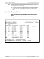
Narrowband Redundant Device
View Information on the Narrowband Redundant Device in
Slot 1
1. From the DXC-100 Main Menu, select Nest Summary. The following menu
appears:
Standby SMC not present
Alarm Contacts..: Enabled
Nest #1 Slot Summary Menu
N+1
Slot# Group Configured Type
----- ----- --------------01
Nb
+ Octal T1/E1
02
Nb
- Octal T1/E1
03
Nb
+ Octal T1/E1
04
Nb
+ Octal T1/E1
05
Nb
+ Octal T1/E1
06
Bb-2 + Hybrid DS-3
07
Bb-2 + Hybrid DS-3
08
STS-1
09
STS-1
10
Bb-1 + Hybrid DS-3
11
Bb-1 + Hybrid DS-3
SMCA
System Manager A
SMCB
System Manager B
PSX
ProtectionSwitch
N+1 Redundancy State: Enabled
Alarm Contact Type..: Standard
Device State
-----------Online
Standby
Online
Online
Online
Online
Standby
Online
Online
Online
Standby
Standby
Online
Online
Alarm
----*None
*Major
None
None
None
None
None
None
None
None
None
None
None
None
[C]lear error counts
[T]oggle Alarm Contacts
N+1 Device Redundancy: Switch[O]ver
[R]estore
Clock Src
[E]xpose
Figure 3-10. Nest Summary Menu
DXC-100PSX
Setting Up Multiple NDRGs
3-9
Chapter 3 Configuration Instructions
Installation and Operation Manual
10. Position your cursor on slot 1 and press <Enter>. The following menu
appears:
Main Menu
----------Protected Slot: 02
View Configuration
Diagnostics
Utilities
N+1 Redundancy
About
Figure 3-11. D8E1T1 Secondary Device
Since slot 1 is established as the redundant device, it is only viewable as a status
screen.
As you can see from the D8E1T1 device’s Main Menu (Figure 3-11), a switchover
has occurred and the D8E1T1 redundant device is protecting the D8E1T1 primary
device resident in slot 2. If a switchover had not occurred, the Protected Slot field
would read “none”. Consequently, if you displayed the slot information for a
primary device configured in a Narrow- band Redundancy Group, the Protected
Slot field would not be there.
4
From the screen shown in Figure 3-11, you can view the device’s configuration,
access utilities, view the redundancy state, and display module identification.
With the exception of viewing the redundancy state, you can go to the relevant
narrowband or broadband application module chapter to learn more about the
View Configuration, Diagnostics, Utilities, and the About sub- menus and their
functionality.
5
The N+1 Device Redundancy submenu can be accessed from both the device’s
Main Menu and the Diagnostics submenu.
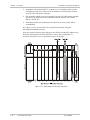
Setting Up a Broadband Redundancy Group
The Broadband Redundancy Group can contain up to eleven configured
broadband devices. These devices reside in slots 8 through 11 for Broadband
Redundancy Group 1, and in slots 1 through 7 for Broadband Redundancy Group
2. Like the Narrowband Redundancy Groups, it is not necessary to have all
broadband devices in the nest be part of a Broadband Redundancy Group.
broadband devices not configured as part of the Redundancy Group will not be
part of the Redundancy Group by default. You must actually configure the device
to be part of the Redundancy Group.
Each Broadband Redundancy Group can only have one Broadband Redundant
Module. This device must reside in slot 11 for a configured Broadband 1
Redundancy Group, and in slot 7 for a configured Broadband 2 Redundancy
Group. If the device is not in those respective slots or if it has not been
configured as a part of the Broadband Redundancy Group or enabled, then the
Redundancy Group switchover will not occur.
3-10
Setting Up Multiple NDRGs
DXC-100PSX
Installation and Operation Manual
Chapter 3 Configuration Instructions
It is important to note here that there is no priority structure to an Redundancy
Group. In other words, the first primary card in the Redundancy Group to fail is
the one that will be switched. Should another primary card in the Redundancy
Group fail while the redundant card is in use, another switchover will not take
place.
To establish a Broadband Redundancy Group, you must go to the Slot
Configuration Menu. Refer to the System Configuration chapter in the DXC-100
User Guide for specific details on configuring a slot. For Broadband Group 1,
configure slot 11 for the broadband redundant device; and configure slots 8
through 10 with broadband primary devices. For Broadband Group 2, configure
slot 7 for the broadband redundant device; and configure slots 1 through 6 with
broadband primary devices.
Note
You do not have to configure all of the slots (8, 9 and 10 for Broadband
Redundancy Group 1, and 1 through 6 for Broadband Redundancy Group 2) in the
DXC-100 nest with the broadband devices but note that any device other than a
broadband device will not be recognized as part of that Broadband Redundancy
Group, and therefore is not protected.
Configuring a Broadband Redundancy Group is detailed on the following pages.
Configure a Broadband Redundancy Group
1. From the DXC-100 Main Menu, select System Configuration, then select Nest
Profile. The following menu appears:
Nest #1 : Profile
Nest name: default node name
Nest type:.............................:
Dual System Mgr........................:
Alarm Contacts Type....................:
Number of Rings for Modem Auto-Answer..:
Nest Dual Power Supplies...............:
DXC-10011
Yes
Standard
2
No
N+1 Redundancy Nest....................:
Protection Switch Dual Power...........:
N+1 Redundancy Narrowband Group........:
N+1 Redundancy Broadband Group 1.......:
Protection Switch Dual Broadband Groups:
N+1 Redundancy Broadband Group 2.......:
Yes
No
Octal T1/E1
HDS-3
Yes
HDS-3
Figure 3-12. The Nest Profile Menu
11. Carefully read each field on this menu, and set up your system based on your
equipment and software. To enable redundancy, select Yes at the N+1
Redundancy Nest field. To enable a second Broadband Group, select Yes at
the Protection Switch Dual Broadband Groups field. HDS-3 (DT3 and DE3) will
be the N+1 Redundancy Broadband Group 1 and Broadband Group 2 types
DXC-100PSX
Setting Up Multiple NDRGs
3-11
Chapter 3 Configuration Instructions
Installation and Operation Manual
available; configure your Broadband Group(s) as appropriate. Octal E1/T1
(D8E1T1) will be the N+1 Redundancy Narrowband Group type.
12. Go back to the DXC-100 Main Menu and select System Configuration, then
select Slot Configuration. The following menu appears (Figure 3-13):
6
13. Position the cursor next to the slot you want to configure and press <Enter>.
The following menu appears:
Slot Configuration
Nest............: 1
Slot............: 2
Slot Name.......: HDS3 #1
Card Type.......: HDS-3
Redundancy...: Enable
Figure 3-13. Card Slot Menu
14. Move your cursor to the Slot name field and press <Enter>, type in a slot
name, and press <Enter> again. In the above example, HDS3 #1 is the named
slot.
15. Move your cursor to the Card type field and press <Enter> to scroll through
the card options until the desired card type appears. In the case of a
Broadband Group, select HDS-3 (DT3 or DE3).
16. Move your cursor to the Redundancy field and press <Enter> until Enable is
displayed.
Note
To “enable” redundancy for the Broadband Redundancy Group you must have
selected DT3 or DE3 as the card type.
17. To exit and save changes, press X. When prompted: “Update Configuration?
Are you sure? (Y/N)” press Y. You are returned to the Slot Configuration
Menu.
3-12
Setting Up Multiple NDRGs
DXC-100PSX
Installation and Operation Manual
Chapter 3 Configuration Instructions
Broadband Redundant Device
To view information on the Broadband redundant device in slot 11 (Broadband
Redundancy Group 1) or 7 (Broadband Redundancy Group 2), invoke the Nest
Summary Menu. Position your cursor on the specific broadband redundant device,
in this case slot 11, and press <Enter>. The following screen appears:
Main Menu
---------Protected Slot: 10
View Configuration
Diagnostics
Utilities
N+1 Redundancy
About
Figure 3-14. Broadband Redundant Device
As you can see from the device’s Main Menu, shown in Figure 3-14, a switchover
has occurred and the DT3 or DE3 redundant device is protecting the DT3 or DE3
primary device resident in Slot 10; the redundant device in slot 11 is view-only. If
a switchover had not occurred, that field would read “none”. Consequently, if you
displayed the slot information for a primary device configured in a Broadband
Redundancy Group, the “Protected Slot” field would not be there.
7
From the screen shown in Figure 3-14, you can access utilities, view the device’s
configuration, redundancy state, and display module identification. With the
exception of viewing the redundancy state, you can go to the relevant
narrowband or broadband device chapter to learn more about the View
Configuration, Diagnostics, Utilities, and the About submenus and their
functionality.
8
N+1 Redundancy State
The following N+1 Redundancy States are available when you configure the slot:
•
Enable - The system will continue to display information about the N+1
Redundancy logic, even though the redundancy state for the specific slot
remains enabled.
•
Disable - The cards in a redundant group are no longer actively protected;
thus a switchover cannot occur.
•
Freeze - Does not permit the N+1 Redundancy logic from updating the
system; thus, the last result of the N+1 Redundancy is displayed.
In most cases, there will be a one-to-one correspondence with what you set as
the N+1 Redundancy State and the actual state accepted by the DXC-100. In the
case where this does not occur, the N+1 Redundancy State is enabled and the
N+1 Redundancy State reflected on the Nest Summary menu is frozen due to a
missing Protection Switch cable.
DXC-100PSX
Setting Up Multiple NDRGs
3-13
Chapter 3 Configuration Instructions
Note
Installation and Operation Manual
Disable is not a selection under N+1 Redundancy States; however, it will appear
on your Nest Summary Menu when you reset your DSMC.2 or power down the
Protection Switch.
For example, Freeze may be selected as the N+1 Redundancy state, see the slot
summary menu in Figure 3-15. As long as the system accepts the state, it will be
confirmed and appear on the Nest Summary Menu as Frozen, see Figure 3-16.
For more information on the N+1 Redundancy State field, see the Nest Summary
chapter.
9
1
Nest #1 Slot Configuration Menu
Slot# Device Type Name Redundancy
----- ---------------- ------ -----------1 Octal T1/E1 NB Standby Enable
2 Octal T1/E1 Input 1 Enable
3 Octal T1/E1 Input 2 Enable
4 Octal T1/E1 Input 3 Enable
5 Octal T1/E1 Input 4 Enable
6 HDS-3 HDS3 1 Enable
7 HDS-3 BB2Standby Enable
8 STS-1 STS1 1 Disable
9 STS-1 STS1 2 Disable
10 HDS-3 HDS32 Enable
11 HDS-3 BB2Standby Enable
N+1 Redundancy: Freeze
N+1 Redundancy Switchover: Automatic
N+1 Redundancy Restore: Manual
Figure 3-15. N+1 Redundancy State Selected
In our example, the N+1 Redundancy State field reads Frozen, as shown in
Figure 3-16.
1
3-14
Setting Up Multiple NDRGs
DXC-100PSX
Installation and Operation Manual
Databases: NotInSync!!!
Alarm Contacts..: Enabled
Nest #1 Slot Summary Menu
N+1
Slot# Group Configured Type
----- ----- --------------01
Nb
+ Octal T1/E1
02
Nb
- Octal T1/E1
03
Nb
+ Octal T1/E1
04
Nb
+ Octal T1/E1
05
Nb
+ Octal T1/E1
06
Bb-2 + Hybrid DS-3
07
Bb-2 + Hybrid DS-3
08
STS1
09
STS1
10
Bb-1 + Hybrid DS-3
11
Bb-1 + Hybrid DS-3
SMCA
System Manager A
SMCB
System Manager B
PSX
ProtectionSwitch
Chapter 3 Configuration Instructions
N+1 Redundancy State: Frozen
Alarm Contact Type..: Standard
Device State
-----------Online
Standby
Online
Online
Online
Online
Standby
Online
Online
Online
Standby
Standby
Online
Online
Alarm
----None
None
None
None
None
None
None
None
None
None
None
None
None
None
[C]lear error counts [T]oggle Alarm Contacts
N+1 Device Redundancy: Switch[O]ver
[R]estore
[E]xpose
Figure 3-16. N+1 Redundancy State Confirmed
N+1 Redundancy Switchover
The Protection Switch is capable of being configured to automatically back up
narrowband and broadband modules in the DXC-100. The N+1 Device
Redundancy (NDRG) Switchover can be configured to occur automatically for one
or both types of NDRGs. Although not advisable, the switchover can also be set
to Manual.
Configure N+1 Redundancy Switchover Options
1. From the DXC-100 Main Menu, select System Configuration, then Slot
Configuration. The Slot Configuration Menu appears:
DXC-100PSX
Setting Up Multiple NDRGs
3-15
Chapter 3 Configuration Instructions
Installation and Operation Manual
Nest #1 Slot Configuration Menu
Slot#
----1
2
3
4
5
6
7
8
9
10
11
Device Type
---------------Octal T1/E1
Octal T1/E1
Octal T1/E1
Octal T1/E1
Octal T1/E1
HDS-3
HDS-3
STS-1
STS-1
HDS-3
HDS-3
Name
-----NB Standby
Input 1
Input 2
Input 3
Input 4
HDS3 1
BB2Standby
STS1 1
STS1 2
HDS32
BB2Standby
N+1 Redundancy:
N+1 Redundancy Switchover:
N+1 Redundancy Restore:
Change Card = [Enter key]
Configuring
Redundancy
-----------Enable
Enable
Enable
Enable
Enable
Enable
Enable
Disable
Disable
Enable
Enable
Enable
Automatic
Manual
[D]elete Card
[P]ort/Link
Figure 3-17. Slot Configuration Menu
18. Move your cursor to the N+1 Redundancy Switchover field, and press <Enter>
until the desired setting is obtained. The possible settings are as follows:
Narrowband Auto - This setting enables a switchover to automatically
occur on just the narrowband devices in a Narrowband Redundancy
Group.
Broadband Auto 1 - This setting enables a switchover to automatically
occur on just the primary broadband devices located in slots 8-10 in a
Broadband 1 Redundancy Group.
Broadband Auto 2 - This setting enables a switchover to automatically
occur on just the primary broadband devices located in slots 1-6 in a
Broadband 2 Redundancy Group.
Automatic - This setting enables a switchover to automatically occur on
an established Redundancy Group.
Manual - A switchover will not occur until the operator does so manually.
Note
The changes made to the N+1 Redundancy State are recorded dynamically. You
must exit the screen in order for your changes to take effect.
19. Once the desired setting is made, press X to exit and save.
Note
There is no confirmation screen for this action.
3-16
Setting Up Multiple NDRGs
DXC-100PSX
Installation and Operation Manual
Chapter 3 Configuration Instructions
After establishing your Narrowband Redundancy Group, exit the Slot
Configuration Menu and go to the Nest Summary screen, see Figure 3-18. The
1
Nest Summary screen displays a status of each application module in the nest,
the status of the device cards configured for redundancy, the status of the
System Manager Controller boards, and the status of the Protection Switch.
Standby SMC not present
Alarm Contacts..: Enabled
Nest #1 Slot Summary Menu
N+1
Slot# Group Configured Type
----- ----- --------------01
Nb
+ Octal T1/E1
02
Nb
- Octal T1/E1
03
Nb
+ Octal T1/E1
04
Nb
+ Octal T1/E1
05
Nb
+ Octal T1/E1
06
Bb-2 + Hybrid DS-3
07
Bb-2 + Hybrid DS-3
08
STS-1
09
STS-1
10
Bb-1 + Hybrid DS-3
11
Bb-1 + Hybrid DS-3
SMCA
System Manager A
SMCB
System Manager B
PSX
ProtectionSwitch
N+1 Redundancy State: Enabled
Alarm Contact Type..: Standard
Device State
-----------Online
Standby
Online
Online
Online
Online
Standby
Online
Online
Online
Standby
Not Present
Online
Not Present
[C]lear error counts [T]oggle Alarm Contacts
N+1 Device Redundancy: Switch[O]ver
[R]estore
Alarm
----*None
*Major
None
None
None
None
None
None
None
None
None
None
None
None
Clock Src
[E]xpose
Figure 3-18. Nest Summary Menu
The N+1 Group column displays the type of group, broadband or narrowband,
that you have configured. As stated earlier in this chapter, the DXC-100PSX can
support multiple redundancy groups, including multiple broadband groups. Nb is a
narrowband redundancy group that can be established in slots 1 through 11, with
slot 1 configured as the secondary slot; Bb-2 is a broadband redundancy group
that can be established in slots 1 through 7, with slot 7 configured as the
secondary slot; Bb-1 is a broadband redundancy group that can be established in
slots 8 through 11, with slot 11 configured as the secondary slot.
The pluses (+) and minuses (-) you see displayed on the screen (Figure 3-18)
distinguish the cards configured as part of an active Redundancy Group and the
card that has been switched over.
1
To qualify for the (+), the configured device type must be correct, the slot
redundancy in the Slot Configuration Menu must be enabled, the NDR group must
have a configured and enabled redundant device, and the Protection Switch must
be Online.
The (-) indicates the card is not just a part of an active Redundancy Group but
that the device has switched over to the redundant module.
DXC-100PSX
Setting Up Multiple NDRGs
3-17
Chapter 3 Configuration Instructions
Installation and Operation Manual
Refer to the Nest Summary Menu in Figure 3-18, as noted in the Device State
column, the redundant device in slot 1 is Online and actively protecting a failed
device in slot 2 of the Narrowband Redundancy Group. In this scenario, the T1/E1
primary device is in Standby mode (i.e., waiting to be Restored). A Restore can
only be performed manually by the operator. Additional information on Restoring
After A Switchover is discussed later on in this chapter. For more detailed
information on Device States or the Nest Summary Menu, refer to the
Management chapter of this manual.
1
Alarms
The Alarm column displayed on the Nest Summary Menu is used to indicate an
error or problem(s) with the device or port. Alarm conditions are designated as
Major, Minor, and/or Critical. To discover specific details about the cause of the
alarm, press E to expose the alarm. For more detailed information on Alarms,
refer to the Alarms chapter in the DXC-100 User Guide.
On the Nest Summary Menu, next to the Alarm column, error conditions are
indicated by an asterisk (*) to the left of the status condition. The asterisk is a
flag for error conditions such as Bipolar Violations, CRCs, BERT errors, etc. The
asterisk can be cleared by pressing C. However, as long as errors are occurring,
the asterisk will appear on the screen.
The Toggle Alarm Contacts field is useful if you have an external alarm panel that
can be physically connected to the DSMC.2 rear interface board. If you have an
external alarm device, you can enable this feature to invoke an audible or visual
notification should an alarm occur. You can disable the alarm from here, as well.
Note
Critical Alarms within a redundancy group will cause a switchover to occur.
View Narrowband N+1 Device Redundancy Details
1. From the Narrowband redundant device’s Main Menu, place your cursor on
the N+1 Redundancy field and press <Enter>. The following screen appears:
N+1 Redundancy Menu
------------------Protected Slot: 02
Device Redundancy
Figure 3-19. N+1 Redundancy Menu - Narrowband (D8E1T1) Redundant Device
20. Place your cursor on the Device Redundancy field and press <Enter>. The
following display appears:
3-18
Setting Up Multiple NDRGs
DXC-100PSX
Installation and Operation Manual
Chapter 3 Configuration Instructions
N+1 Redundancy Status Menu
Member of Redundancy Group: Yes
Card Type.................: Secondary
Device State..............: Online
Frame Sync Pulse.............:
System Clock.................:
Backplane Timeslot Management:
Communication with System Mgr:
Rear Card....................:
Framers......................:
State
Change Count
--------------------OK
0
OK
0
OK
0
OK
0
OK
0
OK
0
[ C]lear counters
Figure 3-20. N+1 Redundancy Status Menu - Narrowband (D8E1T1) Redundant Device
From this menu you can view the status of the D8E1T1 device that is established
as the redundant device. As shown in Figure 3-20, the device is Online, which, in
this case means the redundant device is passing traffic for the primary card. All
events generated are reported under the slot number of the redundant device.
1
Note
The N+1 Redundancy Status Menu for a Primary Device displays the same fields.
The Card Type field is, of course, dependent upon the installed module.
View Broadband N+1 Device Redundancy Details
1. From the Broadband device’s Main Menu, place your cursor on the N+1
Redundancy field and press <Enter>. The following screen appears:
N+1 Redundancy Menu
------------------Protected Slot: 10
Device Redundancy
Figure 3-21. N+1 Redundancy Menu - Broadband (DT3 or DE3) Redundant Device
21. Place your cursor on the Device Redundancy field and press <Enter>. The
following screen appears:
DXC-100PSX
Setting Up Multiple NDRGs
3-19
Chapter 3 Configuration Instructions
Installation and Operation Manual
N+1 Redundancy Status Menu
Member of Redundancy Group: Yes
Card Type.................: Secondary
Device State..............: Online
Frame Sync Pulse.............:
Backplane Timeslot Management:
Communication with System Mgr:
Rear Card....................:
Framers......................:
State
Change Count
--------------------OK
0
OK
0
OK
0
OK
0
OK
0
[C]lear counters
Figure 3-22. N+1 Redundancy Status Menu - Broadband (DT3 or DE3) Redundant Device
From this menu you can view the status of the DT3 or DE3 device that is
established as the redundant device. As shown in Figure 3-22, the device is
Online, which, in this case means the redundant device is passing traffic for the
primary card. All events generated are reported under the slot number of the
redundant device.
1
Note
The N+1 Redundancy Status Menu for a Primary Device displays the same fields.
The Card Type field is, of course, dependent upon the installed card.
3.4
Accessing the Main Menu
If you have a Protection Switch coupled with the DXC-100 system and
operational, you will be able to access the Protection Switch Main Menu.
Access the DXC-100PSX Main Menu
1. From the Nest Summary Menu, the DXC-100PSX device state should read
Online. If so, move your cursor to the DXC-100PSX field and press <Enter>.
The following menu appears.
Main Menu
--------Status
Utilities
About
Figure 3-23. Protection Switch Main Menu
3-20
Accessing the Main Menu
DXC-100PSX
Installation and Operation Manual
Chapter 3 Configuration Instructions
22. To access any of the menus on the Protection Switch Main Menu, place your
cursor on the desired field and press <Enter>.
Table 3-4. Protection Switch Submenu Functions
Submenu
Function
Status
View the status of the Switch box, whether a device has been switched, which slot a
redundant device is protecting, and if the device is missing a cable, not present or okay.
Utilities
Reset the device.
About
Displays information about the software release and version, and details about the
Interface Module.
3.5
Status Menu
Access the DXC-100PSX Status Menu
1. From the Nest Summary Menu, the DXC-100PSX device state should read
Online. If so, move your cursor to the DXC-100PSX field and press <Enter>.
The Protection Switch Main Menu (Figure 3-23) appears.
1
23. From the Protection Switch Main Menu, move your cursor to the Status field
and press <Enter>. The Protection Switch Status Menu appears:
Status Menu
----------Slot# Card Type
Card Status
Switch State
Switch Status
---------------------------------------------------------------------------01
Narrowband Redundant
Ok
Switched protect slot 02 Ok
02
Narrowband Primary
Ok
Switched
Ok
03
Narrowband Primary
Ok
Normal
Ok
04
Narrowband Primary
Ok
Normal
Ok
05
Narrowband Primary
Ok
Normal
Ok
06
Broadband '2' Primary
Ok
Normal
Ok
07
Broadband '2' Redundant Ok
Normal
Ok
08
Broadband '1' Primary
Cable Missing Normal
Ok
09
Broadband '1' Primary
Ok
Normal
Ok
10
Broadband '1' Primary
Ok
Normal
Ok
11
Broadband '1' Redundant Ok
Normal
Ok
Power Supply A Status.: Ok
Fan Maintenance: Auto
Power Supply B Status.: Fault
Fan Speed......: Low
Chassis Temperature...: 85 F/29 C
Fan #01: Ok
Fan #02: Ok
Fan #03: Ok
Figure 3-24. Protection Switch Status Menu
The fields contained in the Protection Switch Status Menu are displayed in
Table 3-5.
1
DXC-100PSX
Status Menu
3-21
Chapter 3 Configuration Instructions
Installation and Operation Manual
Table 3-5. DXC-100PSX Status Menu Field Descriptions
Field
Description
Slot#: (display field)
Displays the slot numbers in the N+1 Protection Switch, from 1 to 11.
Card Type: (display field)
Displays the type of card installed in the associated slot. It will be one of the
following:
•
Narrowband Redundant (slot 1 only)
•
Narrowband Primary (slots 2 to 11)
•
Broadband '2' Primary (slots 1 to 6 only)
•
Broadband '2' Redundant (slot 7 only)
•
Broadband '1' Primary (slots 8 to 10)
•
Broadband '1' Redundant (slot 11 only)
•
Card Not Present.
Card Status:
(display field)
Displays the status of the card in the DXC-100PSX. The status will either be Ok,
Cable Missing or Not Present.
Switch State:
(display field)
Displays the state of the relay switch. The status will either be Normal or
Switched.
Switch Status:
(display field)
Used to indicate if there is a discrepancy between the switchover command from
DSMC.2 and the position of the relay. The status will either be Ok, Not Present,
protect slot xx, or Malfunction. If Malfunction is indicated, immediately contact
RAD Technical Support Department.
Power Supply A Status:
(display field)
Displays the status of Power Supply A in the N+1 Protection Switch. It will either
register Ok or Fault.
Power Supply B Status:
(display field)
Displays the status of Power Supply B in the N+1 Protection Switch. It will either
register Ok or Fault.
Chassis Temperature:
(display field)
Displays the ambient temperature detected inside of the of the N+1 Protection
Switch and DXC-100.
Fan Maintenance:
(option field)
Sets the fan speed for the N+1 Protection Switch. The available settings are Auto,
Low, Medium, and High. When the N+1 Protection Switch unit powers up, the fan
speed default is Auto. The fan speed is based on the temperature inside the N+1
Protection Switch, which is directly related to the surrounding temperature. When
the system is at Auto, the fan speed changes automatically depending upon room
temperature. When Auto is on, the fan settings are as follows:
•
Low - below 30 degrees C (86 degrees F)
•
Medium - 30 degrees C (86 degrees F) to 40 degrees C (104 degrees F)
•
High - above 40 degrees C (104 degrees F)
You can also manually set the fan speed to Off, Low, Medium or High.
Note: Taking the fan out of Auto mode is inadvisable.
Fan Speed: (display field) Displays the current fan speed as Off, Low, Medium, or High.
Fan #01, #02, #03:
(display field)
3-22
Status Menu
These fields display the status of each of the fans as either Ok or Fault.
DXC-100PSX
Installation and Operation Manual
Chapter 3 Configuration Instructions
Cooling Fan Controls
The Protection Switch has a secondary function of providing auxiliary cooling for
the DXC-100. There are three fans in the assembly used for the cooling system.
The Fan Speed field in the Protection Switch Status Menu indicates the speed of
the fans in response to the ambient temperature and the status of the fans.
When the Protection Switch unit powers up, the fan speed default is Auto. The
fan speed is based on the temperature inside the Protection Switch, which is
directly related to the room ambient. When the system is at Auto, the fan speed
changes automatically depending upon room temperature. When Auto is on, the
fan settings are as follows:
•
Low - below 30 degrees C (86 degrees F)
•
Medium - 30 degrees C (86 degrees F) to 40 degrees C (104 degrees F)
•
High - above 40 degrees C (104 degrees F)
If the Protection Switch is not in Auto mode, you can set the fan speed directly
to Off, Low, Medium or High.
An alarm will occur if one of the following conditions is present:
Note
•
cooler - the fan will throttle down when the temperature cools.
•
fan problem - if there is a problem with one of the fans, an alarm will occur.
Taking the fan out of Auto mode is inadvisable.
Change the Fan Setting
1. From the DXC-100 Nest Summary Menu, place your cursor on the
DXC-100PSX field and press <Enter>.
24. From the Protection Switch Main Menu, place your cursor on the Status field
and press <Enter>. The following menu appears:
DXC-100PSX
Status Menu
3-23
Chapter 3 Configuration Instructions
Installation and Operation Manual
Status Menu
----------Slot# Card Type
Card Status
Switch State
Switch Status
---------------------------------------------------------------------------01
Narrowband Redundant
Ok
Normal
Ok
02
Narrowband Primary
Ok
Normal
Ok
03
Narrowband Primary
Ok
Normal
Ok
04
Narrowband Primary
Ok
Normal
Ok
05
Narrowband Primary
Ok
Normal
Ok
06
Broadband '2' Primary
Ok
Normal
Ok
07
Broadband '2' Redundant Ok
Normal
Ok
08
Card Not Present
Not Present
Not Present
Not Present
09
Card Not Present
Not Present
Not Present
Not Present
10
Broadband '1' Primary
Ok
Normal
Ok
11
Broadband '1' Redundant Ok
Normal
Ok
Power Supply A Status.: Fault
Power Supply B Status.: Ok
Chassis Temperature...: 85 F/29 C
Fan Maintenance: Auto
Fan Speed......: Low
Fan #01: Ok
Fan #02: Ok
Fan #03: Ok
Figure 3-25. Protection Switch Status Menu
25. Place your cursor on the Fan Maintenance field and press <Enter>. Toggle
between the following options to change the fan’s speed:
Auto
Off
Low
Medium
High.
As you toggle between options in the Fan Maintenance field, the corresponding
option will appear in the Fan Speed field (it will take approximately 2-3 seconds
for the corresponding option to appear). The only option that will not correspond
is the Auto option. The Fan Maintenance field will indicate Auto while the Fan
Speed field will register either Low, Medium or High. The speed setting is chosen
automatically by the controller card, with the setting dependent on the
temperature of the environment in which the Protection Switch is located.
3-24
Status Menu
DXC-100PSX
Installation and Operation Manual
3.6
Chapter 3 Configuration Instructions
Utilities Menu
The DXC-100PSX Utilities Menu allows you to re-initialize the Protection Switch
Controller Card as done upon power up.
During this boot up cycle, no user data will flow. Since the configuration resides
on the DSMC.2, the current N+1 Redundancy setup will be restored.
Reset the Protection Switch Controller Card
1. From the DXC-100 Nest Summary Menu, place your cursor on the
DXC-100PSX field and press <Enter>.
26. From the Protection Switch Main Menu, place your cursor on the Utilities field
and press <Enter>. The following menu appears:
Utilities Menu
-------------Reset Board
Figure 3-26. DXC-100PSX Utilities Menu
27. With your cursor on the Reset Board field, press <Enter>. The following
prompt appears:
Utilities Menu
-------------************************************
*
*
*
-MESSAGE!*
*
*
*
*
*
Reset this Card?
*
*
*
*
*
*
Are you sure (Y/N)?
*
*
*
************************************
Figure 3-27. DXC-100PSX Reset Card Prompt
28. Press Y to reset the DXC-100PSX Controller Card. A message appears stating:
“-ALERT!- Please wait while we establish communications with the system
manager! Press any key to continue.”
29. Press any key. If this does not return you to the previous menu, press <Ctrl>
and the C key simultaneously.
DXC-100PSX
Utilities Menu
3-25
Chapter 3 Configuration Instructions
Installation and Operation Manual
The Switchover Command
The DSMC.2 controls the NDR and determines that a switchover is necessary. The
DSMC.2 directs the switchover to the redundant device in the Redundancy Group.
Once the switchover occurs, the ports lose traffic. While the redundant device is
in use, no other primary device failures can be switched. The primary device’s
configuration is copied to the redundant device. The primary device’s
configuration is preserved.
Manual Switchover
A switchover can be executed if the operator wants to take the primary card
offline for maintenance purposes.
The Switchover command, performed by the Administrator, Provisioning or Test
level user (refer to the System Configuration chapter for a description of user
levels), forces the primary device to switchover and go offline.
To perform a manual switchover, go to the Nest Summary Menu, place your
cursor on the primary device slot, and press “O”. A switchover done in this
manner is referred to as a manual switchover. The next two screens are
representative of a succession of screens that show a switchover in progress and
a successful switchover. Press X to return to the previous menu.
Switchover command state
Nest 1 Primary Slot 10 Secondary Slot 11
Switchover: Secondary card arming in progress
.
Figure 3-28. Switchover in Progress
Switchover command state
Nest 1 Primary Slot 10 Secondary Slot 11
Switchover: Successful
Figure 3-29. Switchover Successful
Automatic Switchover
To enable the automatic switchover function, you must go to the Slot
Configuration Menu and set the N+1 Device Redundancy Switchover command to
automatic. In this case, a switchover will occur automatically, without user
intervention.
A switchover occurs when a primary device in an Redundancy Group has failed
and met one or more of the error conditions described in Table 3-6.
1
3-26
Utilities Menu
DXC-100PSX
Installation and Operation Manual
Chapter 3 Configuration Instructions
Table 3-6. Error Conditions That Cause Switchovers
Error Conditions
Switchover Occurrence
Frame Sync pulse: Missing (bus error)
A frame sync pulse error occurs when there is a problem from the
SMC by sending a wrong pulse or the device is not receiving the
pulse correctly
System Clock: Missing (bus error)
The system clock is lost
Backplane Timeslot Management: Invalid The backplane is inundated with too many timeslots
(bus error)
Communication with System Manager:
Lost (bus error)
The device has not received any messages from the SMC and the
device responds that it is not present
Rear Card: Missing (bus error)
Rear card is not detected. The device will reset once the rear card
has been detected
Framer: Bad (general error)
A framer is bad. There is a mismatch between the current value
read from the hardware and the values recorded by the software
Restoring after a Switchover
Restoring can only be accomplished manually via the Nest Summary Menu. When
a previously offline primary device is in standby mode, the Restore command
forces the selected device to online.
If the selected device can not be restored (i.e., switched over) an error message
will appear on the screen and no other action will occur.
3.7
About Menu
The DXC-100PSX About Menu displays information about the DXC-100PSX rear
card hardware revision levels and the software and hardware revision levels for
the Protection Switch Controller Card.
Access the DXC-100PSX About Menu
1. From the DXC-100 Nest Summary Menu, place your cursor on the
DXC-100PSX field and press <Enter>.
30. From the Protection Switch Main Menu, place your cursor on the About field
and press <Enter>. The following menu appears:
DXC-100PSX
About Menu
3-27
Chapter 3 Configuration Instructions
Installation and Operation Manual
About Menu
---------Slot#
Rear Card Rev
======================
01
1
02
0
03
1
04
1
05
1
06
0
07
0
08
Not Present
09
Not Present
10
0
11
0
Software Version.........: 2.4a
Software Release Date....: July 2, 2003
Software Checksum........: 6FC1
PSX Controller Card......: Rev 1
PSX Backplane............: Rev 1
Multi-Broadband Groups...: Enabled
Figure 3-30. DXC-100PSX About Menu
Field Descriptions for this menu are provided in Table 3-7.
2
Table 3-7. DXC-100PSX About Menu Field Descriptions
Field
Description
Slot #: (column)
Displays the slot number of the DXC-100PSX rear cards.
Rear Card Rev:
(column)
Displays the hardware revision level of the DXC-100PSX rear cards.
Software Version:
(display field)
Displays the software version currently residing in the DXC-100PSX Controller
Card’s flash memory.
Software Release Date:
(display field)
Displays the date of the PSX Controller Card’s module software release.
Software Checksum:
(display field)
Displays the sum of all bytes in the PSX Controller Card’s flash memory at power
up. Also used to identify software version.
PSX Controller Card:
(display field)
Displays the hardware revision level of the PSX Controller Card.
PSX Backplane:
(display field)
Displays the hardware revision level of the DXC-100PSX backplane.
Multi-Broadband Groups: Displays whether Broadband Group 2 functionality is Enabled or Disabled.
(display field)
3-28
About Menu
DXC-100PSX
Appendix A
Replacing the DXC-100PSX
Fan
A.1
Scope
The Protection Switch can detect a change in fan speed. The slow condition could
be due to a failure of a fan such as worn bearings, open winding in the motor or
shorted winding in the motor. If a fan fails, the entire fan assembly unit must be
replaced.
Note
Before removing the fan assembly, make sure the fans are turned off. Refer to
the procedure on changing the fan setting.
A.2
Fan Assembly Replacement Procedure
1. From the Protection Switch Main Menu, select the Status field and press
<Enter>. The Protection Switch Status Menu appears.
2. Place your cursor on the Fan Maintenance field and press <Enter> to toggle
between the options. Change the setting to Off.
3. Locate the grille containing the filter on the front of the Protection Switch.
Unscrew the four screws on the grille and remove the grille from the
Protection Switch.
4. Turn the four knurled nuts counter-clockwise to remove the fan assembly.
Figure A-1. Front View of Fan Assembly
5. Disengage the fan connector from the PC board and pull out the defective
fan assembly.
6. Engage the replacement fan assembly connector to the PC board, making
sure it is properly connected.
DXC-100PSX
Fan Assembly Replacement Procedure
A-1
Appendix A Replacing the DXC-100PSX Fan
Installation and Operation Manual
7. Place the replacement fan assembly into position making sure the wiring is
clear of the Protection Switch chassis. Line up the fan assembly unit with the
threaded bolts. Turn the knurled nuts until tight.
8. Replace the grille assembly.
9. Go back to the Status Menu, scroll down to the Fan Maintenance field and
press <Enter> to change the fan position to Auto.
Note
A-2
If a fan fails, the entire fan assembly must be replaced.
Fan Assembly Replacement Procedure
DXC-100PSX
24 Raoul Wallenberg Street, Tel Aviv 69719, Israel
Tel: +972-3-6458181, Fax +972-3-6483331, +972-3-6498250
E-mail: [email protected], Web site: http://www.rad.com
Customer Response Form
RAD Data Communications would like your help in improving its product documentation.
Please complete and return this form by mail or by fax or send us an e-mail with your
comments.
Thank you for your assistance!
Manual Name:
DXC-100PSX Ver. 16.2
Publication Number:
371-210-05/10
Please grade the manual according to the following factors:
Excellent
Good
Fair
Poor
Very Poor
Installation instructions
Operating instructions
Manual organization
Illustrations
The manual as a whole
What did you like about the manual?
Error Report
Type of error(s) or
problem(s):
Incompatibility with product
Difficulty in understanding text
Regulatory information (Safety, Compliance, Warnings, etc.)
Difficulty in finding needed information
Missing information
Illogical flow of information
Style (spelling, grammar, references, etc.)
Appearance
Other
Please list the exact page numbers with the error(s), detail the errors you found (information missing,
unclear or inadequately explained, etc.) and attach the page to your fax, if necessary.
Please add any comments or suggestions you may have.
You are:
Who is your distributor?
Your name and company:
Job title:
Address:
Direct telephone number and extension:
Fax number:
E-mail:
Distributor
End user
VAR
Other
Publication No. 371-210-05/10
Order this publication by Catalog No. 803482
International Headquarters
24 Raoul Wallenberg Street
Tel Aviv 69719, Israel
Tel. 972-3-6458181
Fax 972-3-6498250, 6474436
E-mail [email protected]
North America Headquarters
900 Corporate Drive
Mahwah, NJ 07430, USA
Tel. 201-5291100
Toll free 1-800-4447234
Fax 201-5295777
E-mail [email protected]
www.rad.com
The Access Company