1
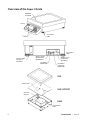
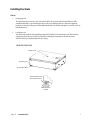
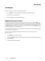
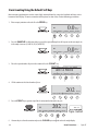
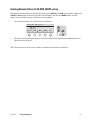
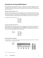
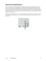
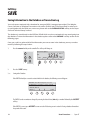
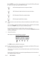
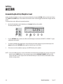
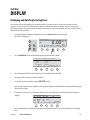
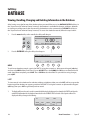
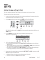
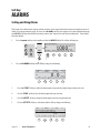
Super II
TM
User Manual
Setra Systems, Inc
Weighing Systems Division
159 Swanson Road
Boxborough, MA 01719
SS2067 Rev E 0704
Table of Contents
Introduction
Introduction ................................................................................................................................................... 3
Overview of the Super II Scale ................................................................................................................ 6
Installing Your Scale .................................................................................................................................... 7
Understanding Your Scale ........................................................................................................................ 10
Keypad: Soft Keys .......................................................................................................................... 10
Keypad: Alphanumeric Keys ...................................................................................................... 11
Keypad: Hard Keys ......................................................................................................................... 11
LEDs ................................................................................................................................................... 12
Display Symbols ............................................................................................................................ 12
Back of the Controller ................................................................................................................. 12
User Functions
Basic Weighing .............................................................................................................................................15
Weighing/Counting with a Container .................................................................................................15
Basic Counting Using the Default Soft Keys .....................................................................................16
Entering Numeric Values for ID, APW, COUNT, or TARE ..................................................................17
Entering Alphanumeric Information into the ID Registers Using the Scale Keypad ..........18
Counting with Accuracy Enhancement ..............................................................................................19
Reverse Counting or Kitting ....................................................................................................................20
Operating Your Scale Using a QWERTY Keyboard ..........................................................................21
Adjusting the Backlighting Option ......................................................................................................23
Soft Key: SAVE ...............................................................................................................................................24
Soft Key:ACCUM ..........................................................................................................................................26
Soft Key:DISPLAY .........................................................................................................................................27
Soft Key:DATBASE .......................................................................................................................................28
Soft Key:SET PTS ..........................................................................................................................................30
Soft Key:ALARMS ........................................................................................................................................31
Soft Key:UNITS .............................................................................................................................................33
Soft Key:COUNTER ......................................................................................................................................34
Appendix A: Glossary of Terms ...............................................................................................................35
Appendix B: Limited Two Year Scale Warranty .................................................................................36
FCC Warning .................................................................................................................................................37
Index ................................................................................................................................................................38
Introduction
Super II • Introduction
3
4
Introduction • Super II
Introduction
Thank you for purchasing a Setra Super II™ scale. Its ease of operation and durable construction should
provide years of reliable service. While your scale is easy to operate, it is advisable to read this guide before
use in order to help you perform weighing, counting, and related operations quickly and accurately.
The Super II scale comes with two separate manuals labeled “User Manual” and the “Supervisor and
Technical Manual”. The “User Manual” is all that is necessary to be able to operate the scale in its default
state. It explains all basic weighing and counting operations as well as how to print and use some of the
more advanced features such as the database and the setpoints. The Supervisor and Technical Setups in
the “Supervisor and Technical Manual” are for programming various features in your scale such as print
formats, sample sizes and database usage as well as performance characteristics of your scale – calibration,
resolution, and display update rate.
Due to the large amount of customization that can be programmed into your scale, it may not operate
exactly the same way as in its default state. One advanced programming option is to have your scale
follow a “Macro” which is a pre-programmed number of steps. Your scale can always be returned to its
default state within Supervisor, Bases, and Technical Setup Menus (see “Supervisor and Technical Manual”).
Typographical conventions used in both manuals include the following:
1.
Bold characters indicate keys on the scale keypad whether they are prompts listed above the soft keys or hard
keys or any of the alphanumeric characters.
2.
“Quotation marks” enclose messages that will appear on the scale’s display.
3.
nnn indicates that a number will appear in the display message.
Super II • Introduction
5
Overview of the Super II Scale
WEIGHING
PLATFORM
DISPLAY
ADJUSTABLE
FOOT
KEYPAD
ADJUSTABLE
FOOT
BATTERY DOOR
(BATTERY IS
OPTIONAL)
ON/OFF SWITCH
(WITH BATTERY
OPTION ONLY)
DC POWER
CONNECTOR
REMOTE SCALE
CONNECTOR
(OPTIONAL)
ADDITIONAL
SETRA BASE
CONNECTOR
PAN
BUBBLE LEVEL
PAN SUPPORT
LOAD CELL
MODULE
TRANSPORTATION
HOLDER FOR THE
AC ADAPTER
BASE
PAN SUPPORT
STOPS
6
Introduction • Super II
Installing Your Scale
Setup
1.
Locating your scale.
The rugged design of your Super II scale ensures that it will be able to operate well in the typical factory or office
environment. Nonetheless, you should always treat your scale as you would any other piece of precision equipment,
locating it on a clean dry surface, protected from draft and vibration. CE certification only applies to use of the scale in an
Indoor Environment.
2.
Leveling your scale.
Your scale has four adjustable feet with locking mechanisms. The bubble level is located in the center underneath the
weighing pan. Once your scale is level, the feet should be locked into place by turning the star lock nut counterclockwise until it is pressing firmly against the base casting.
LEVELING THE SCALE
BUBBLE LEVEL
STAR LOCK NUT
ADJUSTABLE FOOT
TURN CLOCKWISE TO
LOCK FOOT IN PLACE
TURN TO ADJUST
HEIGHT
Super II • Introduction
7
3.
Connecting the controller.
Attach the coiled cord coming out of the Super II weighing base to the port marked BASE on the underside of the
controller. If you would like to mount the controller to the base, refer to the diagram below.
1. Line up the controller with the three spring loaded screw washers on the base.
2. Press the controller onto the base in order to engage the screw heads and slide the controller to the left.
3. Press down on the controller to secure it into place.
To remove the controller, reverse the procedure listed above.
1. Lift up on the controller until it reaches its upper limit.
2. Move it down slightly as you slide it to the right.
3. Once in its farthest right position, the controller can be wiggled off.
ON
8
OFF
Push in
Lift up
Slide to left
Slide to right
Press down
Wiggle off
Introduction • Super II
4.
Powering the scale.
The Super II scale comes standard with a 16V AC adapter designed to both power the scale and recharge the optional
internal battery. It is recommended to first plug the AC adapter into an electrical outlet before connecting to the back of
the scale. Once you have plugged your scale into a live outlet, it is automatically on. If the scale is equipped with
the internal battery option, the on-off switch on the rear panel must be in the ‘on’ position to power-up the scale.
The scale draws very little current from an outlet and may be left connected. This keeps your scale ready to use with no
warm-up time.
5.
Display test.
When your scale is first powered on, it displays the programmed time and date along with a greeting message that may
be either Setra Systems’ address and telephone number or that of the dealer who sold you the scale. There is also a
count down procedure that lasts around thirty seconds during which time the controller pulls information from the base
before settling on Ø.ØØ weight. For best accuracy, allow the scale to warm up for 5 minutes or longer if changing
environmental surroundings.
6.
Experimenting with your scale.
Reference to this “User’s Guide” along with the “Supervisor and Technical Setups” manual is the best way to learn about
your scale and take full advantage of all its features. However, the Super II functionality and menu system is designed
to be fully “prompt” driven. Experimenting with either the default keys or entering the menu by pressing the menu
hard key will not alter your scale as long as you do not change the settings in either the Technical, Bases, or Supervisor
setups. All menu selections end with an EXIT soft key that will bring you back to the main menu. There is also a reset
hard key that clears all scale registers and brings you back to Ø.ØØ weight.
Super II • Introduction
9
Understanding Your Scale
Keypad: Soft Keys
The Super II keypad is divided into three groups of keys. The first set of keys underneath the display are
referred to as “soft keys”. Their function changes depending on where you are in the counting procedure
or which level you enter in the menu.
The default soft keys are listed below and have the following functions:
ZERO
Assigns the pan and whatever is currently being weighed a value of zero. While the
scale is determining a stable weight reading, the display will indicate “Zero Base
Process Activated”. A zeroing operation underway can be cancelled with a second pass of
the ZERO key.
Note: If a Tare value is stored in memory, it will be cleared.
SAMPLE
Determines a stable reference point and displays the preprogrammed sample sizes
(10, 25, 50, 100 pieces). A SAMPLE size selection menu can be displayed if activiated in
the Supervisor setups (see SAMPLE soft key in the “Supervisor and Technical Setups
Manual”.
COUNT
Instructs the scale to begin or resume counting.
PRINT
Instructs the scale to print preprogrammed fields or label format. If multiple label
formats are active, a print menu is displayed in order to make a numeric
print register selection.
CLEAR
Used to switch from Count (pieces) to Weight.
LRG SPL
Used to go to the next programmed sample size. For example, to go from “ADD 10
PIECES” to “ADD 25 PIECES”.
UPDTAPW
Used to recalulate the APW based on a larger sample size. The additional sample
weight cannot exceed 100% of the previous sample to avoid the compounding of
errors (see Counting with Accuracy Enhancements in this User Manual).
EXIT
Returns the display to either Weight or Count(pieces) depending on which was last
active before the menu prompt.
10
Introduction • Super II
Keypad: Alphanumeric Keys
The second set of keys are the alphanumeric keys. These keys are used to enter numbers or values into the
scale as well as alphanumeric information into the various ID registers. The default key functions are
represented by the numbers on the bottom. To access the alpha characters or punctuation above the
numbers, the abc hard key must be pressed. “ABC” will appear in the lower left side of the display indicating that you are now in the alpha entry mode. The
left arrow is a backspace and the ➔ right arrow is
used either as a space or to move on to the next alpha character. Alphanumeric data entry into the Super II
follows the cellular telephone standard (see Entering Alphanumeric ID’s in this User Manual for more
information).
➔
ABC
DEF
GHI
1
2
3
JKL
MNO
PQR
4
5
6
STU
VWX
YZ,
7
8
9
: # ;
–
0
.
Keypad: Hard Keys
The last set of keys are referred to as the hard keys. There are five hard keys that have the following functions:
tare
Instructs the scale to accept a numerical tare weight entry. If a container is placed on the pan,
pressing tare assigns its weight as the “tare” (i.e. container weight), saves it to memory and
displays it on the top line of the display. The weight or count displayed will then read net
value (i.e. content weight or count).
menu
Instructs the scale to enter the menu system. The soft keys will change to new functions. The first
two levels of the menu system are user functions followed by a branch into either the Technical
or Supervisor menus (see fold out for the Main Menu Tree of the “Supervisor and Technical
Setups” manual).
remote Instructs the scale to switch to a secondary base (either strain gauge or Setra base) attached to
the primary base connected to the controller. If multiple bases are attached or daisy chained, a
menu will appear to allow base selection by numeric entry.
abc
Instructs the scale to go into alpha entry mode. “ABC” will appear on the bottom left of the
display and pressing an alphanumeric key will scroll through the alpha selection (see entering
Alpha/Numeric ID’s for more information).
reset
Sets all counting and weighing registers to zero. Clears all volatile ID fields and assigns the pan
(and anything on the pan) a value of Ø.ØØ weight.
Super II • Introduction
11
LEDs
There are two LEDs on the keypad that are only active when the battery option is installed and in use.
low battery
“red”
Indicates that the battery needs to be charged.
charging
“green”
Indicates that the battery is being charged.
Display Symbols
OK
Reading shown is stable.
ABC
Alphanumeric keypad is in the letter entry mode.
------
The reading is outside the calibration range.
OL
The ----- is indicating an overload situation.
UL
The ----- reading is indicating an underload situation.
GROSS The weight displayed is the gross weight on the pan including any tare wieght.
Back of the Controller
There are five ports labelled on the bottom of the controller. Their functions are as follows:
BASE
Port for connection to Setra base.
KEYBOARD
Port for connection to optional computer PS2® style QWERTY keyboard(not available from
Setra). For CE compliance, Setra has certified the use of Behavior Tech Computer
Corporation’s Model BTC 5210 keyboard. Other manufacturer’s keyboards may or may not
affect the limitations set forth in CE certification. Setra cannot be responsible for other
manufacturer’s specifications.
BI
Bi-directional RS232 communications port for connection to a computer. Default port
settings are 9600 baud, 8 data bits, no parity, 1 start, and 1 stop bit, hardware handshaking
on (RTS/RTC).
OUT
RS232 output port for connection to a serial printer. Default port settings are 2400 baud, 8
data bits, no parity, 1 start, and 1 stop bit for the DYMOSetra Labelwriter 250 printer, no
hardware handshaking.
IN
RS232 input port for connection to a bar code scanning device. +5V is supplied on pin 6.
Default port settings are 2400 baud, 8 data bits, no parity, 1 start, and 1 stop bit for Setra
Linear Imager Gun (403678) or Smart Wand (403676), no hardware handshaking.
®PS2 is a registered trademark of International Business Machines
12
Introduction • Super II
User Functions
Super II
•
User Functions
13
14
User Functions
•
Super II
User Functions
Basic Weighing
To weigh an object on your scale, use the following procedure:
1.
Press the ZERO key and wait for the display to show Ø.ØØ weight with the “OK” stability indicator on.
2.
Place the object(s) to be weighed on the pan.
3.
Wait for the “OK” symbol, then read the weight from the display.
Weighing/Counting with a Container
To weigh or count objects WITHOUT including the weight of the container, use the tare or ZERO keys. If
you wish to retain the container weight for later reference or to print or display the gross weight, the tare
key should be used. The tare weight of the container(s) will be displayed on the top line of the display until
the ZERO or reset key is pressed. If you do not need to retain the container weight, the ZERO key should
be used to eliminate the weight of the container(s).
If the tare weight of the container is known, a full container may be placed on the pan and the tare weight
entered through the numeric keypad.
To tare or zero out the weight of the container, and then weigh or count the contents, use the
following procedure:
1.
Press the ZERO key. Place the container on the pan.
2.
Press the tare or ZERO key. (If the container is not empty and tare weight is known, enter the value using the numeric keypad and
then press the tare key).
3.
Perform your weighing or counting application.
Super II
•
User Functions
15
Basic Counting Using the Default Soft Keys
Most counting applications can be successfully accomplished by using the 5 default soft keys at the
bottom of the display. To count a number of like pieces on the scale, use the following procedure:
1. Place an empty container on the scale. Press the ZERO key.
0.0
OK!
Base 1
Grams
ZERO> SAMPLE> COUNT> PRINT> CLEAR>
2. Press the SAMPLE key. Each time the key is pressed the requested sample size will sequence to the next sample size
in the sample size menu. (i.e. ADD 10, 25, 50, 100 PIECES)
0.0
OK!
Base 1
Grams
ZERO> SAMPLE> COUNT> PRINT> CLEAR>
3. Place the requested number of pieces in the container. Press the COUNT key.
Select sample, add pieces, press COUNT
ADD 10 PIECES
ZERO> LRG SPL> COUNT> PRINT>
4.
EXIT>
Fill the container to the desired number of pieces.
202
Pieces
ZERO> SAMPLE> UPDTAPW PRINT> CLEAR>
5. Press the PRINT key to generate a tape/label or to transmit the data to the out port.
OK
202
Pieces
ZERO> SAMPLE> UPDTAPW> PRINT> CLEAR>
6.
16
202 CS
Tape /Label
Remove the pieces from the container and press the CLEAR key to return the scale to the weight display.
User Functions
•
Super II
Entering Numeric Values for ID, APW, COUNT, or tare
The numeric keypad can be used for entering values for the PART ID, the APW (average piece weight), the
COUNT, or tare weight. Additional ID registers are available by pressing the MORE soft key. To enter
known values into those registers, follow the procedure below:
1.
Press any of the numeric keys. The 5 soft keys change to the following:
Enter ID, Tare, APW, or Count.
1234
PART ID
2.
APW
tare
COUNT
MORE
EXIT
enu
remote
abc
reset
When you are finished entering the number, press the desired soft key below the display or press the tare hard key to enter
that value into the scale register.
NOTE: Numeric entry uses the scale’s “medium” size font and is limited to 16 characters.
Super II
•
User Functions
17
Entering Alphanumeric Information into the ID Registers Using the
Scale Keypad
The alphanumeric keypad can be used for entering information into the various ID registers for printing or
database record purposes. There are 10 ID registers numbered 0-9. The first 7 ID registers have been given
common field names listed below. To change the name of an ID field, please refer to the ID NAME soft key
in the Supervisor menu of the “Supervisor and Technical Setups “ manual. Please note that the database
does all its sorting based on the IDØ field named PART ID.
Upon pressing the abc hard key, the 5 soft keys change to the following:
Enter ID Field:
tare
ABC
PART ID
LOT #
DESC
MORE
EXIT
menu
abc
remote
reset
Additional ID registers are available by pressing the MORE key:
Press
MORE
once
for
or
twice
for
E nt er I D Fie ld:
ABC
OPRTR ORDER# VENDOR MORE
EXIT
Enter ID Field:
ABC
REV#
ID7
ID8
ID9
EXIT
To enter alphanumeric information into any of the the ID registers, after typing in your entry, press the
soft key for the desired field. The ID registers have a limitation of 23 characters each.
Alphanumeric Entry (Cellular Telephone Style)
To enter letters into the scale, press the abc hard key on the scale keypad. “ABC” should appear on the
bottom left above the soft keys. While “ABC” is displayed, the alphanumeric keypad is in the alphabet
mode. The first time a key is pressed, it displays the first letter listed above the number. Pressing the key
again moves to the second character and once again for the third character. When the desired character is
displayed, you can move on to the next character simply by pressing the next key or the right arrow ( ➔).
The right arrow is necessary when two characters that share the same key follow one another. Letters and
numbers can be mixed by simply turning on or off the letter entry mode by pressing the abc key.
18
User Functions
•
Super II
Counting with Accuracy Enhancement
When counting parts that are not uniform in weight, it is possible to periodically update the average piece
weight (APW) and thereby increase the accuracy. Each time the UPDTAPW key is pressed, the scale will
update the APW as long as the additional weight is less than or equal to the previous sample weight. If the
added weight is more than 100% of the previous sample, the APW will not be updated. For example,
starting with a sample size of 10 pieces, add 10 more and press the UPDTAPW key. The APW will be
recalculated based on a 20 piece sample. When adding 11 or more to the original 10 piece sample, the
APW will not be updated. To count using this accuracy enhancement feature, follow the procedure below.
1.
Place an empty container on the scale and press the ZERO or tare key.
2.
Press the SAMPLE key. The scale display will read “ADD 10 Pieces.”
(The sample size requirement can be increased by pressing the LRG SPL key repeatedly. The factory default sample sizes
are: 10, 25, 50 and 100 PIECES. This sequence of programmed sample sizes will repeat itself as the LRG SPL key is pressed.)
3.
When the desired sample size is reached, place the requested number of pieces in the container.
4.
Press the COUNT key. Wait for the “OK” symbol, then slowly add pieces until the displayed count is increased by 100% or
less.
5.
Press the UPDTAPW key. The scale automatically calculates a new average piece weight based on the larger number of
pieces, and is ready to continue counting.
If “Calculating stable APW” is not displayed on the top line, the additional pieces have exceeded 100% of the previous sample
weight and the APW will not be updated. The message “Unable to recalculate APW: Resample” will be displayed and the scale
will continue counting using the previously calculated APW.
CAUTION: This accuracy enhancement feature is disabled if the average piece weight has been scanned
in from a bar code or entered via a computer or from a numeric keypad.
Super II
•
User Functions
19
Reverse Counting or Kitting
Use this feature to count the number of pieces removed from a full container. This is especially helpful
when kitting (counting out a certain number of pieces to be packed together). To perform reverse counting or kitting, use the following procedure:
1.
Place a container full of pieces you wish to count on the pan.
2.
Press the ZERO key then press the SAMPLE key.
3.
The scale display will read “ADD 10 Pieces”. (The sample size requirement can be increased by pressing the LRG SPL key
repeatedly. The predetermined sample sizes are: 10, 25, 50 and 100 pieces. This sequence of predetermined sample sizes will
repeat itself as the LRG SPL key is pressed.)
4.
When you have selected the desired sample size, remove the indicated number of pieces from the container.
5.
Press the COUNT key.
6.
Remove pieces until the display shows the number of pieces you wish to count out or kit.
7.
Press the ZERO key.
8.
Repeat Steps 6 and 7 as many times as needed.
NOTE: a. If the average piece weight is known, you may press the — key, enter the average piece
weight, and press the APW key in place of Steps 2-5.
b. If the sample size is not large enough to satisfy the minimum accuracy requirement the
display will read “REMOVE nnn MORE”. Remove the specified number of pieces (i.e. nnn) from
the container, then press the COUNT key.
c. It is possible that the required sample size is larger than the quantity needed for each kit. For
instance, the required sample size is 100 pieces but only 50 pieces are to be kitted together. In
this case, follow steps 1 through 5 above, place the 100 piece sample back into the container
and press the ZERO key. Continue with steps 6 through 8 above.
20
User Functions
•
Super II
Operating Your Scale Using a QWERTY Keyboard
The back of the removable controller has a port for a standard PS/2® style computer keyboard. To remove
the controller from the base, please refer to Section 1, Setting Up Your Scale. Once a QWERTY keyboard is
attached to the controller, all scale operations can be performed from the keyboard or in combination with
the scale’s controller.
Using the Function Keys F1 - F5
The function keys F1 - F5 correspond to the soft key functions shown on the bottom of the display. That is,
F1 corresponds to the soft key furthest on the left. F2 corresponds to the second soft key and so on. When
the scale is in the default mode, the F1 key can be used to ZERO the scale, the F2 key will recall the SAMPLE
size, the F3 key will initiate a COUNT, the F4 key will PRINT, the F5 key will CLEAR and return to weight.
Example functions in the default menu:
F1 = ZERO
F2 = SAMPLE
F3 = COUNT
F4 = PRINT
F5 = CLEAR
Using the Function Keys F8 - F12
The F8 - F12 function keys have been reserved for the following hard key functions. F8 is equivalent to the
tare key. F9 will bring up the menu. F10 will switch to a remote base (or bring up the base selection
menu if multiple bases are attached). F11 will bring up the ID entry soft keys (abc key) and F12 will cause
the scale to do a complete reset of all volatile scale registers.
Hard key
function:
F8 = TARE
F9 = MENU
F10 = REMOTE
F11 = ABC
F12 = RESET
Entering Numeric Information
The number keys 1 - 9 function the same way as they do on the scale’s numeric keypad. Once a number is
pressed, the soft keys change to the following:
Numeric
soft key
labels:
Enter ID, Tare, APW, or Count.
F8
tare
1234
PART ID
APW
COUNT
MORE
EXIT
F9
menu
F11
remote
F1
F2
F3
F4
F5
F10
abc
F12
reset
PS/2® is a registered trademark of IBM.
Super II
•
User Functions
21
To enter a value into one of the above registers , use the function key F1 - F3 that corresponds to the
desired soft key (ex: F2 for entering an APW value). Use the F9 key to enter a tare value. Use the F5 Key to
EXIT.
Entering Alphanumeric ID Information
Once a letter is pressed, the scale’s display changes to the ID entry mode. At this point, there are two ways
of entering the information into the ID register. The function keys F1 - F4 are available to select registers
and move throughout the menu. Another method is to press the ALT key followed by a number between 0
and 9, depending upon the register to be accessed.
Enter ID Field Value:
F8
tare
ABC
22
PART ID
LOT #
DESC
MORE
EXIT
F9
menu
F11
remote
F1
F2
F3
F4
F5
F10
abc
F12
reset
Alphanumeric ID entry
using ALT key:
Alphanumeric ID entry
using function key:
ALT + 1 =
ALT + 2 =
ALT + 3 =
ALT + 4 =
ALT + 5 =
ALT + 6 =
ALT + 7 =
ALT + 8 =
ALT + 9 =
ALT + 0 =
F1=
F2=
F3=
F4=
PART ID
LOT #
DESC
MORE
F1=
F2=
F3=
F4=
OPRTR
ORDER #
VENDOR
MORE
F1=
F2=
F3=
F4=
F5=
REV#
ID7
ID8
ID9
EXIT
OPRTR
ORDER #
LOT #
DESC
VENDOR
REV #
ID7
ID8
ID9
PART ID
User Functions
•
Super II
Adjusting the Backlighting Option
Super II controllers which are equipped with optional display backlighting are also equipped with controls to vary the brightness of the backlighting. An additional feature of the backlighting control is the
automatic battery detector which differentiates between power delivered from an AC adapter and that
from an internal or external battery. The power source will determine the maximum level of backlighting
available to the display to control power consumption if the battery power saving features have been set
through the Technical Menu.
➔
To adjust the backlight brightness, press and hold the abc key and simultaneously press the left arrow
key repeatedly to reduce brightness or the ➔ right arrow key repeatedly to increase brightness to the
desired level.
ABC
DEF
GHI
1
2
3
JKL
MNO
PQR
4
5
6
STU
VWX
Y Z,
7
8
9
:# ;
.
–
Super II
•
User Functions
0
tare
menu
abc
remote
reset
23
Soft Key:
SAVE
Saving Information to the Database or Transaction Log
Your scale comes equipped with a database for storage of APW’s (average piece weights), Tare Weights,
Counts, Set Points or complete Transactions with various ID fields and a Time/Date stamp. In order to set
up your database for the fields you want to use, please refer to the DATBASE SETUP soft key in the “Supervisor and Technical Setups” manual.
The database is sorted based on the IDØ/Part ID field which must be associated with any record going into
the database. To view the information in the database, please refer to the DATBASE soft key section in the
following pages.
Once your scale has gathered all of the information you want to store in the database, you may save that
record by following the steps below:
1.
Press the menu hard key on the controller. The soft keys will change to:
Select Menu Option:
tare
menu
abc
2.
Press the SAVE soft key.
3. a.
Saving to the Database
OK!
remote
SAVE
ACCUM
1234
DISPLAY DATBASE
Base 1
Pieces
MORE
reset
If the PART ID already has a record associated with it in the database, the following screen will appear:
CAUTION: This ID already has a record.
Hit ACCEPT to overwrite or enter new ID.
PART ID: ABC-123
ACCEPT
EXIT
The PART ID can be overwritten or changed by entering the desired letter (abc key) or number followed by the ACCEPT
soft key.
If the PART ID is correct, press ACCEPT to move on to the field saving screen in section b if using a database format that
keeps track of the count.
24
User Functions
•
Super II
When the ACCEPT key is pressed for an existing record where the count is being saved, the following soft keys appear
(see “Supervisor and Technical Setups” manual for DATBASE SETUP options).
ADD CT
ADD CT will add the displayed Count to the Count register in the database.
SUB CT
SUB CT will subtract the displayed Count from the Count register in the database.
UPD A/T
UPD A/T will update the APW and/or Tare weight in the database.
UPD ALL
UPD ALL will update all available fields in the database.
NOTE: A record cannot be saved to the Database without an identification number (PART ID ) for that
record.
You can set up database security features that will prevent the changing, deleting, or addition of records to the database.
Please refer to the SECURTY soft key in the “Supervisor and Technical Setups” manual.
If you already know the information to be stored in the database, and do not need the scale to
develop the needed information (such as an APW), you can enter the record through the DATBASE soft key functions
described on the following pages.
b.
Saving to the Transaction Log
When saving to the Transaction Log, the following screen will appear:
Press SAVE to record the following:
PART ID: ABC-123
COUNT:1000
SAVE
ON:12:00
1/01/00
GO BACK
Press SAVE to confirm the recording of the listed transaction:
NOTE: The fields displayed for Transaction Log recording are selectable in the TRANSAC/SETUP menu in
the “Supervisor and Technical Setups” manual.
Transactions for non-scale counted parts can be recorded by manually entering the count in the Transaction Log Saving
Screen listed above.
If both the Database and the Transaction Log are turned on, the program will prompt you to choose between the two
before displaying the appropriate Saving screen.
Super II
•
User Functions
25
Soft Key:
ACCUM
Accumulating Results by Weight or Count
Various displayed weights or counts can be accumulated by using the ACCUM soft key in the User’s Menu.
The CLEAR and COUNT keys in the Default User Menu can be used to toggle between the weight and the
count.
To accumulate results, follow the procedure below:
1.
Once the desired weight or count is displayed, press the menu hard key on the controller.
The soft keys will then change to:
S e l e c t Me nu O p t io n :
OK!
tare
menu
abc
remote
SAVE
ACCUM
1234
DISPLAY DATBASE
Base 1
Pieces
MORE
reset
2.
Press the ACCUM soft key and the scale will then load the Weight or Count into the “ACCUM WT:” or “ACCUM CT:” register
and display it on the top line.
3.
To continue accumulating the weights for the same part from the same batch, simply put on your new load and press the
menu hard key and the ACCUM soft key again as described in steps 1 and 2 above.
4.
To clear out or reset the accumulator register, press the RESET hard key on the controller.
NOTE: Counts for different pieces can be individually accumulated in the Database by simply saving each
batch. See the SAVE soft key in the previous pages and the DATBASE FORMAT soft key in the
Supervisor Menu of the “Supervisor and Technical Setups” manual to choose the database selection for storing counts.
26
User Functions
•
Super II
Soft Key:
DISPLAY
Displaying and Deleting Scale Registers
At any time during the weighing or counting process, you may recall or display any number of scale
registers in order to view the information or delete it. There are seven (7) weight registers and ten (10)
ID registers that can have information in them at any time. To view and/or delete any of the scale registers,
follow the procedure below:
1.
At any time during the weighing or counting process, press the menu hard key on the controller.
The soft keys will change to:
Select Menu Option:
tare
menu
abc
2.
OK!
remote
SAVE
ACCUM
0.00
DISPLAY
Base 1
Grams
DATBASE
MORE
reset
Press the DISPLAY soft key and the following menu appears that looks as follows:
Select item to display by numeric entry
1. ID
5. Acc Weight
2. APW
6. Gross
3. Tare
7. Net
4. Acc Count
8. Count
GO BACK
EXIT
3.
Press the number key for the desired register (ex: press the number 2 to view the APW).
4.
The register and its associated value will be displayed.
5.
You can then delete that value by pressing the DELETE soft key.
Note: You cannot delete the gross weight as it is the weight currently on the platform and the net weight will only change by
deleting the tare weight.
6.
If more than one ID register is active when the number 1 is pressed to display the ID, a new menu with all 10 ID registers is
displayed:
Select ID Field to display:
ID0.
ID1.
ID2.
ID3.
PART ID
OPRTR
ORDER #
LOT #
ID4. DESC
ID5. VENDOR
ID6. REV #
ID7.
ID8.
ID9.
GO BACK
7.
Press the numerical key associated with the ID register and display that register (ie. Press 0 to display Part ID or 3 to display
Lot #).
Super II
•
User Functions
27
Soft Key:
DATBASE
Viewing, Recalling, Changing and Deleting Information in the Database
After having set up the format of the database that you would like to use (see DATBASE SETUP soft key in
the “Supervisor and Technical Setups” manual), the database is available for changes, additions, deletions
or viewing any of the records that are stored in the database unless protected (see SECURTY soft key in
the “Supervisor and Technical Setups” manual). To access the database records, follow the steps below:
1.
Press the menu hard key on the controller; the soft keys will change to:
S e l e c t Me nu O p t io n :
tare
menu
abc
2.
OK!
remote
SAVE
0.00
Base 1
Base 1
Pieces
Grams
ACCUM DISPLAY DATBASE MORE
reset
Press the DATBASE soft key; the soft keys then change to:
Enter the PART ID below:
NEW
LIST
EXIT
NEW
To add a new database record , type in the PART ID using the numeric or alphanumeric keypad (abc key)
and press the NEW softkey. Enter Part ID, press ACCEPT. Press the DOWN and UP keys to select fields and
enter data. When complete, press SAVE. Press CLEAR to clear that field. To quit without saving changes,
press QUIT.
LIST
To view records in the database for selection, editing, or deletion, either press the LIST soft key to go to the
beginning of the database or type any portion of the PART ID using the numeric or alphanumeric keypad
(abc key), then press LIST to go directly to that record.
1.
The display will show the next 4 records in numerical/alphabetical order that most closely match the PART ID and show the
variable field information for the database format chosen in the DATBASE SETUP selections of the Supervisor Menu. The
display and soft keys change to the following:
ID
PRIOR
NEXT
RECORD RECORD
28
APW
ACCEPT
TARE
VIEW/ GO BACK
EDIT
User Functions
•
Super II
2.
a) To move through the database, use either the PRIOR/RECORD(previous) or NEXT/RECORD soft keys.
b) To view the record information in order to load it into or delete it from the temporary scale registers,
press the SELECT key.
c) To change any information in the record, use the EDIT soft key and refer to section below.
Note: The PART/ID cannot be changed once it is stored in the database.
DATABASE RECORD SCREEN
Once the PART ID is selected, the full database record screen is displayed with the following options.
ID:
TARE:
APW:
COUNT
DOWN
UP
ACCEPT
DELETE GO BACK
ACCEPT will load the displayed information into the temporary scale registers.
DELETE will delete the record.
NOTE: A different selection of fields are displayed depending on which Database Format was selected in
the Supervisor Setups.
To change data, use DOWN and UP to move cursor todesired filed, enter data and when done, press SAVE
to save changes. As soon as you begin to type in new data, the soft keys change to:
ID:
TARE:
APW:
COUNT:
DOWN
UP
SAVE
CLEAR
QUIT
Press CLEAR to set all fields to 0. Press QUIT to exit without making changes.
Super II
•
User Functions
29
Soft Key:
SET PTS
Entering, Changing, and Using Set Points
The scale is capable of displaying a TARGET Weight or Count along with LOW and HIGH limits.
To program Set Points, follow the steps below:
1.
Determine the desired weight or count by using the scale’s weighing or counting functions. If you know your desired limits
you can simply enter them in the menu while the scale is at zero.
2.
Press the menu hard key on the controller, and then the MORE soft key. The soft keys will change to:
Select Menu Option:
tare
menu
abc
OK!
remote
MORE
SET PTS
UNITS
1000
Base 1
Base 1
Pieces
Pieces
COUNTER SET UPS EXIT
reset
NOTE: *If ALARMS is enabled, this will be the ALARMS key. Set Point settings will be available from the ALARMS screen. See
ALARMS next page.
3.
Press the SET PTS* soft key and the soft keys change to the following with the weight or count
displayed in the lower right hand corner:
LOW:
0.0
TARGET
0.0
EnterLOW, TARGET, HIGH setpoint or
press % to enter deviation from target:
OK!
Weight :
lOW
TARGET
HIGH
%
HIGH
0.0
0.0
GO BACK
4.
Set Points can be programmed by the following means:
a) To enter the displayed weight or count into either the LOW, TARGET, or HIGH register, press the soft key for the
appropriate position.
b) To enter a value different from the one displayed into either the LOW, TARGET, or HIGH register, type in the desired
value using the numeric keypad followed by the soft key for the appropriate position.
c) You can have the scale automatically calculate the LOW and HIGH limits as a percent deviation from the displayed weight
or count by typing in the allowable percent error using the numeric keypad followed by the % soft key.
5.
For better viewing of the displayed weight or count along with its LOW, TARGET, and HIGH set points, press the GO
BACK soft key to return to the default User Menu.
6.
a) The displayed Set Points can be changed at any time by following steps 1-4 listed above.
b) To delete the Set Points, press the reset hard key on the controller.
30
User Functions
•
Super II
Soft Key:
ALARMS
Setting and Using Alarms
The Super II has three alarm outputs which can be used to signal when the measured weight or count is
within a pre-programmed range. To access the ALARMS soft key, be certain it has been enabled through
the SET PTS soft key of theTechnical setups menu (See “Supervisor and Technical Manual”). Then follow
the steps below:
1.
Press the menu hard key on the controller, and then the MORE soft key. The soft keys will change to:
Select Menu Option:
tare
menu
abc
2.
OK!
MORE
remote
ALARMS
UNITS
1000
COUNTER SET UPS
Base 1
Pieces
EXIT
reset
Press the ALARMS soft key and the soft keys change to the following:
ALARM1
LOW:
ALARM2
0.0 TARGET:
OK!
START
STOP
ALARM3
0.0 HIGH:
O. O
RESET
SET PTS
Stopped
0.0
Grams
GO BACK
3.
Press the START soft key to enable the alarm outputs to respond to the weight/count presently on the scale.
4.
Press the STOP soft key to freeze the alarm outputs in their present state.
5.
Press the RESET soft key to change the alarm outputs to their zero weight/count state.
6.
Press the SET PTS soft key to set the alarms and the soft keys change to the following:
LOW:
0.0 TARGET:
0.0 HIGH:
Enter Low, Target or High setpoint or
press % to enter deviation from target.
OK!
Weight:
LOW
Super II
•
User Functions
TARGET
HIGH
%
0.0
O.O
GO BACK
31
7.
Enter the weight value on the numeric keypad or by placing pieces to be counted on the weighing pan and press the LOW,
TARGET, or HIGH soft key to set the value for each register.
a) To enter a value different from the one displayed into the LOW, TARGET, or HIGH register, type in the
desired value using the numeric keypad followed by the soft key for the appropriate register.
b) You can have the scale automatically calculate the LOW and HIGH limits as a percent deviation from the displayed target
weight or count by typing in the allowable percent error using the numeric keypad followed by the % soft key.
8.
For better viewing of the displayed weight or count along with its LOW, TARGET, and HIGH set points, press the EXIT
soft key to return to the default User Menu.
32
User Functions
•
Super II
Soft Key:
UNITS
Changing the Units of Measure
The scale is capable of displaying weight in eight predefined units of measure as well as a user definable unit of
measure. To name and program the user definable unit of measure or to lock out any units of measure to
prevent misreadings of the display, please refer to the UNITS ON soft key in the Supervisor Menu (see “Supervisor and Technical Setups” manual).
To change units of measure, follow the steps below:
1.
Press the menu hard key followed by the MORE soft key. The soft keys change to the following:
Select Menu Option:
tare
menu
abc
2.
OK!
remote
MORE
SET PTS
UNITS
0.00
Base 1
Base 1
Pieces
Grams
COUNTER SET UPS EXIT
reset
Press the UNITS soft key and the display then changes to the 8 units of measure available.
Select unit to display by numeric entry
1. GRAMS
5. TROY OZ
2. OZ
6. CARAT
3. LBS
7. KG
4. DWT
8. GRAINS
GO BACK
3.
EXIT
To select any of the units displayed, press the corresponding number key.
NOTES:
a. If any units of measure have been disabled, they will appear with a dark background and will
not be available to the user (see UNITS ON soft key in the Supervisor Menu of the “Supervisor and
Technical Setups” manual to enable or disable any units of measurement).
b. The last unit of measure, GRAINS, is a user definable unit of measure and may be named
differently along with a different conversion factor (see UNITS ON soft key in the Supervisor
Menu in the “Supervisor and Technical Setups” manual for naming and programming the user
definable unit of measure).
Super II
•
User Functions
33
Soft Key:
COUNTER
Setting a Print Counter for Box Counting or Serial Number Generation
The scale has the capability of keeping track of a counter each time the PRINT key is used. This counter can
be used to generate sequential numbers for box or package labeling during kitting operations or to
generate a sequential serial number for a label.
To enter the beginning and ending values of a printing sequence, follow the steps below:
1.
Press the menu hard key, followed by the MORE soft key. The soft keys change to the following:
Select Menu Option:
tare
menu
abc
2.
OK!
remote
MORE
SET PTS
UNITS
0.00
Base 1
Base 1
Pieces
Grams
COUNTER SET UPS EXIT
reset
Press the COUNTER soft key and the soft keys change to the following:
X: 0
Y: 0
Enter the desired X and Y limits
followed by the X and Y key.
X UNIT
Y UNIT
GO BACK
EXIT
3.
To enter values for the X unit and Y unit (X being the beginning number in the sequence and Y being the ending number),
type in the desired number using the numeric keypad followed by the appropriate soft key for the X or Y position. The X and Y
counters are limited to 10 numeric characters each.
4.
To return to the default User Menu, press the EXIT soft key.
5.
The X and Y values will remain in memory until X equals Y at which time they will reset to Ø. The counter can also be
deactivated by entering Ø for the X and Y values following steps 1 - 3 above.
NOTES:
a. You do not need to enter a value for X if 1 is the first value in your sequence.
b. Y must be greater than X.
c. You may not enter negative numbers.
34
User Functions
•
Super II
Appendix A
Glossary of Terms
Accuracy
The degree of conformity of a measured value to the true value.
APW
Average Piece Weight: the value calculated by dividing the quantity of parts in
the sample into the weight of the sample. This value is stored in the scale and
divided into the net weight of the bulk load to provide a total count.
Base
The portion of the scale that contains the load cell and receives the object to be
weighed.
Controller
The portion of the scale that includes the keypad, display, battery status, LEDs
and ports for communicating with the scale base and peripheral devices.
Gross Weight
The weight of the contents (net weight) combined with the weight of the
container (tare weight).
ID
Abbreviation for identifier. An identifier can be a part number, lot number, or
item description and can be entered into one of several available fields in the
database.
Kitting
The counting procedure that involves repeatedly counting out small
quantities of a given part to be packaged with other parts that will be used
together in an assembly.
Menu
Refers to the numerous choices presented in the display as labels for the soft
keys.
Net Weight
The weight of the contents of a container, not including the weight of the
container.
QWERTY
Term used to describe the typical keyboard found on a personal computer or
typewriter. QWERTY refers to the top row of letters on the keyboard.
Register
A memory location within the scale where data is stored.
Set Points
Target weight or count values that can be entered into the scale for filling or
checking weighing applications. Set points can be used to indicate when a
weight or count is within a specified range.
Tare
The weight of an empty container. Also, the process of storing the weight of an
empty container and zeroing the scale’s display.
Super II
•
Appendix A
35
Appendix B
Setra Systems, Inc.
Limited Two-Year Scale Warranty
Setra Systems, Inc. warrants the scales it manufactures to be free from defects in material and workmanship. Upon return, transportation charges prepaid, to Setra’s factory within two (2) years of the date of
purchase, Setra will repair or replace, at its option, any scale which it determines to contain defective
material or workmanship and will return said scale to purchaser, transportation prepaid, at any point in the
United States. Setra shall not be obligated, however, to repair or replace scales which have been repaired
by unauthorized parties, abused, improperly installed, altered, or otherwise misused or damaged, even if by
accident, in any way. Setra will not be responsible for any dismantling, reassembly or reinstallation charge.
Nothing in this warranty shall be construed as a warranty for merchantability or fitness for any specific use
or purpose, and this warranty is in lieu of all other warranties, express or implied. Setra shall not be held
liable under the terms of this warranty for any special, indirect, incidental or consequential damages
claimed in connection with the scale’s performance or availability.
Setra Systems, Inc.
Weighing Systems Division
159 Swanson Road
Boxborough, MA 01719
978 263-1400
.
36
Appendix B
•
Super II
FCC Warning
This equipment has been tested and found to comply with the limits for a Class A digital
device pursuant to Part 15 of FCC Rules. These limits are designed to provide reasonable
protection against harmful interference when this equipment is operated in a commercial
environment. This equipment generates, uses, and can radiate radio frequency energy and,
if not installed and used in accordance with the instruction manual, may cause harmful
interference to radio communications. Operation of this equipment in a residential area is
likely to cause harmful interference, in which case, the user must correct the interference.
Canadian Department of Communications
This digital apparatus does not exceed the Class A limits for radio noise emissions from a
digital apparatus set out in the Radio Interference Regulations of the Canadian Department of Communications.
Le présent appareil numerique n’emét pas de bruits radioeléctriques depassant les limités
applicables aux appareils numeriques de la classe a préscrites dans le reglément sur le
brouillage Radioeléctrique Edicté par le Ministre des Communications du Canada.
Super II
37
Symbols
E
------ 12
EXIT 9, 10
A
F
ABC 11, 12
AC ADAPTER 6, 9
AC adapter 9
ACCEPT 24
ACCUM 26
Accuracy 35
ADJUSTABLE FOOT 6, 7
ALARMS 30, 31
Alphanumeric 18
Alphanumeric ID Information 22
Alphanumeric Keys 11
APW 10, 17, 21, 35
F1 - F5 21
F8 - F12 21
FCC 37
Function Keys 21
G
H
B
I
Backlighting 23
BASE 6, 8, 12, 35
BASE CONNECTOR 6
BATTERY 6, 9, 12
BATTERY DOOR 6
BI 12
ID 17, 35
ID NAME 18
ID Registers 18
IN 12
C
KEYBOARD 12
KEYPAD 6, 18
Kitting 21, 35
D
Database 28
database 4
DATBASE 24
DATBASE FORMAT 26
DATBASE SETUP 24, 26
DC POWER 6
DELETE 27
DISPLAY 6, 27
Display 9
display 4, 10
Index
P
PAN 6
PART ID 28
PRINT 4, 10, 16
printer 12
PRIOR/RECORD 29
Q
QWERTY 12, 21, 35
GRAINS 33
Gross Weight 35
HIGH 30, 32
Canadian Department of
Communications 37
charging 12
CLEAR 10, 16, 26
Controller 8, 12, 35
COUNT 10, 17, 26
count 16, 19, 21
Counter 34
Counting 10, 14, 16
Counting , Default 16
ON/OFF SWITCH 6
OUT 12
K
L
label 10
LED 12
LEVEL 6, 7
LEVELING 7
LIST 28
LOAD CELL 6
LOW 30, 32
LRG SPL 10, 19, 21
M
Menu 11, 35
N
Net Weight 35
NEXT/RECORD 29
Numeric Information 21
Numeric Values 17
O
R
Register 27, 35
REMOTE 6, 11
REMOTE SCALE 6
reset 9, 11
Reverse Counting 21
S
SAMPLE 10
sample 16, 19, 21
sample size 10
SAVE 24
Scale Registers 27
Set Points 30, 35
SET PTS 30, 31
Soft Keys 16
T
Tare 11, 14, 35
TARGET 30, 32
U
UL 12
UNITS ON 33
UPDTAPW 10
updtapw 19
W
warranty 36
WEIGHING 6, 14
Weighing/Counting 14
WEIGHINGPLATFORM 6
Z
ZERO 10, 14, 19, 21
zero 16
OK 12
38
Index •
Super II
Super II • Index
39