1
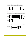
instruction manual
PCS and PCS2
Power Current Sensors
Control System Accessories
AMX Limited Warranty and Disclaimer
AMX Corporation warrants its products to be free of defects in material and workmanship under normal use for
three (3) years from the date of purchase from AMX Corporation, with the following exceptions:
•
Electroluminescent and LCD Control Panels are warranted for three (3) years, except for the display and touch
overlay components that are warranted for a period of one (1) year.
•
Disk drive mechanisms, pan/tilt heads, power supplies, MX Series products, and KC Series products are
warranted for a period of one (1) year.
•
Unless otherwise specified, OEM and custom products are warranted for a period of one (1) year.
•
Software is warranted for a period of ninety (90) days.
•
Batteries and incandescent lamps are not covered under the warranty.
This warranty extends only to products purchased directly from AMX Corporation or an Authorized AMX Dealer.
AMX Corporation is not liable for any damages caused by its products or for the failure of its products to perform.
This includes any lost profits, lost savings, incidental damages, or consequential damages. AMX Corporation is not
liable for any claim made by a third party or by an AMX Dealer for a third party.
This limitation of liability applies whether damages are sought, or a claim is made, under this warranty or as a tort
claim (including negligence and strict product liability), a contract claim, or any other claim. This limitation of
liability cannot be waived or amended by any person. This limitation of liability will be effective even if AMX
Corporation or an authorized representative of AMX Corporation has been advised of the possibility of any such
damages. This limitation of liability, however, will not apply to claims for personal injury.
Some states do not allow a limitation of how long an implied warranty last. Some states do not allow the limitation or
exclusion of incidental or consequential damages for consumer products. In such states, the limitation or exclusion of
the Limited Warranty may not apply. This Limited Warranty gives the owner specific legal rights. The owner may
also have other rights that vary from state to state. The owner is advised to consult applicable state laws for full
determination of rights.
EXCEPT AS EXPRESSLY SET FORTH IN THIS WARRANTY, AMX CORPORATION MAKES NO
OTHER WARRANTIES, EXPRESSED OR IMPLIED, INCLUDING ANY IMPLIED WARRANTIES OF
MERCHANTABILITY OR FITNESS FOR A PARTICULAR PURPOSE. AMX CORPORATION
EXPRESSLY DISCLAIMS ALL WARRANTIES NOT STATED IN THIS LIMITED WARRANTY. ANY
IMPLIED WARRANTIES THAT MAY BE IMPOSED BY LAW ARE LIMITED TO THE TERMS OF THIS
LIMITED WARRANTY.
Table of Contents
Table of Contents
Product Information .................................................................................................1
Specifications .................................................................................................................... 1
Installation .................................................................................................................3
PCS and PCS2 Installation ............................................................................................... 3
Rack mounting the PCS2 .................................................................................................. 3
Wiring Guidelines .............................................................................................................. 3
Preparing captive wires............................................................................................................ 4
PCS to AXC-INP8 .................................................................................................................... 4
PCS2 to AXC-INP8 .................................................................................................................. 5
PCS to Axcent, Axcent2, or Axcent3........................................................................................ 5
PCS2 to Axcent, Axcent2, or Axcent3...................................................................................... 5
PCS to Television Controllers .................................................................................................. 6
PCS2 to Television Controllers ................................................................................................ 6
Calibration .................................................................................................................7
PCS ................................................................................................................................... 7
PCS2 ................................................................................................................................. 7
PCS Calibration................................................................................................................. 7
PCS2 Calibration............................................................................................................... 9
Operation and Programming .................................................................................11
PCS Operation ................................................................................................................ 11
PCS2 Operation .............................................................................................................. 11
PCS2 considerations.............................................................................................................. 11
Programming................................................................................................................... 11
PCS Programming ................................................................................................................. 11
PCS2 Programming ............................................................................................................... 12
PCS and PCS2 Power Current Sensors
i
Table of Contents
ii
PCS and PCS2 Power Current Sensors
Product Information
Product Information
The Power Current Sensors (PCS) and Dual Power Current Sensors (PCS2) provide power current
status for AMX equipment. Examples of such equipment are video projectors, monitors, audio
receivers, and VCRs. The PCS and PCS2 detect the AC current drawn by the equipment plugged
into its AC receptacle. You can adjust either the PCS or PCS2 to detect full on, full off, and standby
power levels.
Specifications
The following tables list specifications for the PCS and PCS2.
PCS Specifications
Dimensions
3.13" x 2.23" x 2.5" (79.5 mm x 56.6 mm x 63.5 mm)
Weight
4 oz. (114 g)
Enclosure
Plastic black matte finish
Power Requirement
12 VDC @ 20 mA minimum
Connectors
4-pin captive screw connector
3-prong, grounded, 120 VAC receptacle
Indicators
• Standby LED
Load Sensitivity
15 A 1800 W maximum (15 A @ 120 VAC maximum)
• On LED
30 mA minimum
PCS2 Specifications
Dimensions
1.51" x 5.55" x 5.45" (38.4 mm x 141.10 mm x 138.4 mm)
Weight
1 lb. 10.8 oz. (816 g)
Enclosure
Metal black matte finish
Power Requirement
120 VAC @ 250 mA minimum
Connectors
6-pin captive screw connector
3-prong, grounded, 120 VAC receptacle
Dry Closure Relay Outputs
0.5 A @120 VAC or 1 A @ 28 VDC
Indicators
• 2 Standby LEDs
• 2 On LEDs
• Power LED
Load Sensitivity
10 A 1200 W maximum (combined fuses)
20 mA 2.4 W minimum 120 W maximum
PCS and PCS2 Power Current Sensors
1
Product Information
2
PCS and PCS2 Power Current Sensors
Installation
Installation
The PCS requires +12 VDC (+11 VDC to +17 VDC @ 20 mA minimum) for operation; the PCS2
is simply plugged into a 120 VAC three-hole wall outlet to obtain power.
PCS and PCS2 Installation
1. Provide +12 VDC power from the Central Controller or external power supply, and connect it
to the port on the PCS. Refer to the Wiring Guidelines section on page 3 for more information.
2. Connect the STBY and ON outputs to the appropriate system inputs. Refer to the Wiring
Guidelines section on page 3 for more detailed information.
3. Plug the unit into the PCS AC receptacle. The term unit refers to the piece of equipment the
PCS or PCS2 is sensing for power status.
4. Plug the PCS into an AC outlet.
Rack mounting the PCS2
To rack mount the PCS2 using the optional AC-RK Accessory Rack Kit:
1. Remove any connected power and communication connectors from the rear panel.
2. Remove the two screws on the front panel of the PCS2.
3. Remove the front panel and the space bracket behind the panel.
4. Remove the rubber feet on the bottom of the unit, if necessary. Insert a scissors blade or other
sharp object into the side of one of the rubber feet and pull it off. Do the same to remove the
other three rubber feet.
5. Place the unit in the appropriate opening in the AC-RK.
6. Place the front panel of the PCS2 on the front of the rack over the unit and secure the front
panel using the two screws removed in step 2.
Wiring Guidelines
The Wiring Specifications table lists wire sizes and the maximum lengths allowable between the
PCS/PCS2 and the Central Controller. The maximum wiring lengths are based on a minimum of
13.5 volts available at the power supply output. The PCS/PCS2 requires a local +12 VDC power to
operate properly. The maximum wiring distance between the power supply and PCS/PCS2 units are
determined by power consumption, supplied voltage, and the wire gauge used for the cable.
To reduce the possible effects of ground loop noise in the video, use a single-source power supply
mounted within distances specified in the following table.
Wiring Specifications
Wire Size
Maximum Wiring Length
18 AWG
29.34 feet (8.94 meters)
20 AWG
18.56 feet (5.66 meters)
22 AWG
11.57 feet (3.53 meters)
24 AWG
7.30 feet (2.23 meters)
PCS and PCS2 Power Current Sensors
3
Installation
Do not connect power to the PCS/PCS2 until the wiring is complete.
Preparing captive wires
You will need a wire stripper and flat-blade screwdriver to prepare and connect the captive wires.
Never pre-tin wires for compression-type connections.
1. Strip 0.25 inch (6.35 mm) of insulation off all wires.
2. Insert each wire into the appropriate opening on the connector according to the wiring
diagrams and connector types described in this section.
3. Turn the flat-head screws clockwise to secure the wire in the connector. Do not over-torque the
screws; doing so can bend the seating pin and damage the connector.
PCS to AXC-INP8
Connect the PCS output ports to the AXC-INP8 input ports as shown in FIG. 1; follow the
illustration for input 1 through input 8. Set the jumpers of the associated inputs on the AXC-INP8
(refer to the AXC-INP8 Switch/Opto Voltage Input Card instruction manual) to Switch mode. All
Switch mode inputs and the CardFrame share common GND.
AXC-INP8
GND
GND
INP1
STBY
GND
ON
INP2
PWR
PCS
CardFrame GND (-)
12 VDC or
external
+
power
supply
FIG. 1 PCS to AXC-INP8
If using a power supply that is independent of the CardFrame, an optional GND wire
is necessary.
4
PCS and PCS2 Power Current Sensors
Installation
PCS2 to AXC-INP8
Connect the PCS2 output ports to the AXC-INP8 input ports, as illustrated in FIG. 2. Follow the
illustration for Input 1 through Input 8. Set the jumpers of the associated inputs on the AXC-INP8
to Switch mode. All Switch mode inputs and the Card-Frame share common GND.
AXC-INP8
GND
COM
INP1
STBY
GND
ON
PCS2
INP2
FIG. 2 PCS2 to AXC-INP8
PCS to Axcent, Axcent2, or Axcent3
Connect the PCS output and power ports to the Axcent, Axcent2, or Axcent3 input/output (I/O)
ports, as illustrated in FIG. 3. Provide 12 VDC power from the Panja system power supply or an
external power supply.
Axcent
Axcent2
Axcent3
GND
GND
I/O 1
STBY
I/O 2
ON
PCS
PWR
GND (-)
12 VDC
+
FIG. 3 PCS to Axcent, Axcent2, or Axcent3
PCS2 to Axcent, Axcent2, or Axcent3
Connect the PCS2 output and power ports to the Axcent, Axcent2 , or Axcent3 input/output (I/O)
ports, as illustrated in FIG. 4.
Axcent
Axcent2
Axcent3
GND
COM
I/O 1
STBY
I/O 2
ON
PCS2
FIG. 4 PCS to Axcent, Axcent2, or Axcent3
PCS and PCS2 Power Current Sensors
5
Installation
PCS to Television Controllers
FIG. 5 illustrates the connections required for the PCS to television controllers.
Television
controllers
GND
GND
I/O 1
STBY
I/O 2
ON
I/O 3
PWR
PCS
I/O 4
PWR
FIG. 5 PCS to television controllers
PCS2 to Television Controllers
FIG. 6 illustrates the connections between the PCS2 to television controllers.
Television
controllers
GND
COM
I/O 1
STBY
I/O 2
ON
PCS2
I/O 3
I/O 4
PWR
FIG. 6 PCS2 to television controllers
6
PCS and PCS2 Power Current Sensors
Calibration
Calibration
The PCS and PCS2 work by setting a threshold. The STANDBY threshold is set be-tween the
current draw of the OFF state and that of the STANDBY state. The ON threshold is then set
between the current draw of the STANDBY state and the ON state.
The PCS2 contains two major circuits, each independent of each other. Each if these major circuits
contain two sub-circuits, the ON and STANDBY circuits. The following paragraphs will address
the sub-circuits for each major circuit of the PCS2.
PCS
The state status for the PCS is:
!
STANDBY senses when the current is at or below standby threshold. The LED lights and
relay switch output is closed when below ON.
!
ON senses when current is at or above ON threshold. The LED lights and relay switch
output is closed when above ON.
!
The circuit (both the ON and STANDBY) can differentiate between 20 mA and 1 A.
Anything above 1 A is sensed as 1 A, regardless if it is 2 A, 6 A, or 10 A.
PCS2
The PCS2 has an inline 10 A fuse for protection. This will allow one, or both major circuits to draw
a maximum of 10 A (1,200 W) total.
The state status for each of the major circuits of the PCS2 is:
!
STANDBY is lit when the sensed current level is above STANDBY threshold.
!
STANDBY remains lit (regardless of its setting) when the ON LED lights.
!
ON is lit when current is above the ON threshold.
!
The circuit (both the ON and STANDBY) can differentiate between 20 mA and 1 A.
Anything above 1 A is sensed as 1 A, regardless if it is 2 A, 6 A, or 10 A.
!
It is not logical for ON to light before STANDBY. As a result, the circuit is de-signed so
that if the ON is lit, the STANDBY will also be lit, regardless of its setting.
When extreme accuracy is required for calibration, it is best to plug the PCS or PCS2 into a wall
outlet at least 15 minutes before calibration to allow the circuitry to warm up. Calibration of the
PCS and PCS2 must be accomplished prior to use. Calibration of the PCS and PCS2 is
accomplished as follows:
PCS Calibration
In the PCS, the ON state is dependent of the STANDBY mode but the STANDBY mode is not
dependent on the ON mode. They work together to provide a final level, where the Standby power
level provides a base and the ON level is an increment to that level. FIG. 7 illustrates the
relationship that the STANDBY and ON power levels have with each other in determining the final
power level.
PCS and PCS2 Power Current Sensors
7
Calibration
ON power level
STANDBY power level
FIG. 7 Standby and On level relationship
If the unit has both STANDBY and ON states, follow these steps:
If the unit only has an ON state, or if the PCS is sensing the ON state, perform step 1.
If you are using only the STANDBY mode, focus on steps 3 and 4.
1. Turn the STANDBY and ON potentiometers (POTs) clockwise until they stop.
2. Plug the PCS into an outlet and plug the unit (the device you are monitoring) into the PCS.
This power provides the unit with power. There are three power conditions that most units
exhibit: ON, Standby, and OFF.
3. Plug an cable from the PCS to a Central Controller to provide power to the PCS unit.
4. Set the unit to the desired STANDBY power mode. This is obtained by plugging the device
into an electrical port and not turning the power switch/button ON.
5. Turn the STANDBY POT counterclockwise until the status LED turns off. Then, turn it slowly
clockwise until the LED turns on.
6. Set the unit (device being monitored) to the ON state.
7. If the STANDBY LED stays on, turn the ON POT counterclockwise until:
!
The ON LED turns on.
!
The STANDBY LED turns off.
8. Set the unit to the Standby mode.
9. If the ON LED stays on, turn the STANDBY POT counterclockwise until:
!
The ON LED turns off.
!
The STANDBY LED turns on.
10. Repeat steps 5 through 9 to calibrate the PCS.
8
PCS and PCS2 Power Current Sensors
Calibration
PCS2 Calibration
When extreme accuracy is required for calibration, allow the PCS2 to warm up for a minimum of
15 minutes before calibration. The following procedures are used for both circuit 1 and circuit 2.
Calibrate each circuit independently.
If the device only has an ON state, either STANDBY or ON can be used in the following steps.
1. Plug the PCS2 into a power source.
2. Connect the device.
3. Turn both POTS all the way counter clockwise. At a maximum, this is 20 full turns. The stop
(end) can be detected by a subtle clicking sound and feel.
4. Set the device to the STANDBY power mode and wait 2-seconds. STANDBY power mode is
obtained by plugging the unit into an electrical port and not turning the power switch ON.
5. Turn the PCS2 STANDBY POT clockwise until the STANDBY LED lights.
6. Slowly turn the POT counterclockwise until the LED goes out. Then, very slowly turn the POT
clockwise until the LED lights. The "turn-on-threshold" has just been determined. It is best not
to set precisely on this threshold, so turn the POT a fraction more clockwise. This fractional
extra turn can be a bit larger for higher power devices and may be almost negligible for very
low power devices.
7. Turn the devices off and wait 2 seconds.
Because of hysteresis (the analog circuit components time for changing states) the
turn-on and turn-off thresholds will not be exactly the same.
8. If the LED is still on, repeat steps 6 through 8 until the LED is not on when the device is turned
off.
9. Perform steps 1 through 8 for the ON circuit level.
10. Repeat steps 1 through 9 for the second PCS2 circuit's STANDBY and ON circuit levels.
PCS and PCS2 Power Current Sensors
9
Calibration
10
PCS and PCS2 Power Current Sensors
Operation and Programming
Operation and Programming
PCS Operation
When properly calibrated, the PCS senses current levels from sources that have one or two levels of
power consumption. The STANDBY LED is on when the following occurs:
!
The PCS is sensing the lower level of current (as low as 30 mA, or 4W at 120 VAC).
!
The STANDBY output is low.
The STANDBY and ON outputs are mutually exclusive. You can adjust the PCS to sense
differences in STANDBY and ON current level as low as 30 mA. The ON LED is on when the PCS
senses the higher operating level of current (up to 15A). If the source is completely off, neither
LED is ON.
PCS2 Operation
When properly calibrated, the PCS2 senses current levels from connected sources that have one or
two levels of power consumption. The PCS2 STANDBY LED is ON when the following occurs:
!
STANDBY is lit when the sensed current level is above STANDBY threshold.
!
STANDBY remains lit (regardless of its setting) when the ON LED lights.
!
STANDBY threshold cannot be set less sensitive than ON threshold.
This requires that the STANDBY circuitry be calibrated for levels between 20 mA and 1 A in order
to differentiate when a connected unit is in a STANDYBY or ON mode.
!
ON is lit when current is above the ON threshold.
!
The circuit (both the ON and STANDBY) can differentiate between 20 mA and 1 A.
Anything above 1 A is sensed as 1 A, regardless if it is 2 A, 6 A, or 10 A (LED ON =
output switch closed).
!
It is not logical for ON to light before STANDBY. As a result, the circuit is designed so
that if ON lights, the STANDBY will light, regardless of its setting.
PCS2 considerations
When connecting a unit/system to the PCS2, be aware that a one or two second PCS2 circuitry
stabilization consideration must be accounted for.
During transitions between states, the PCS2 may take 1 to 2 seconds to stabilize and its initial
output indication may be incorrect. Failure to account for this possible delay may cause the Axcess
or Axcent2 system to repeatedly cycle power on the unit being sensed.
Programming
When properly calibrated, the PCS and PCS2 sense current levels from sources that have one or
two levels of power consumption.
PCS Programming
When programming actions based on the state of the PCS, include the following:
PCS and PCS2 Power Current Sensors
11
Operation and Programming
!
A one- or two-second delay.
!
Verification of status changes.
During transitions between states, the PCS may take 1 to 2 seconds to stabilize and its output
indication may be incorrect. Failure to observe this delay may cause the Axcess, Axcent2, or
Axcent3 system to repeatedly cycle power on the unit being sensed.
PCS2 Programming
When connecting a unit/system to the PCS2, be aware that a 1 or 2 second PCS2 circuitry
stabilization consideration must be accounted for.
During transitions between states, the PCS2 may take 1 to 2 seconds to stabilize and its initial
output indication may be incorrect. Failure to account for this possible de-lay may cause the
Axcess, Axcent2, or Axcent3 system to repeatedly cycle power on the unit being sensed.
12
PCS and PCS2 Power Current Sensors
Operation and Programming
PCS and PCS2 Power Current Sensors
13
brussels • dallas • los angeles • mexico city • philadelphia • shanghai • singapore • tampa • toronto* • york
3000 research drive, richardson, TX 75082 USA • 469.624.8000 • 800.222.0193 • fax 469.624.7153 • technical support 800.932.6993
041-004-1063 3/02 ©2002 AMX Corporation. All rights reserved. AMX, the AMX logo, the building icon, the home icon, and the light bulb icon are all trademarks of AMX Corporation.
AMX reserves the right to alter specifications without notice at any time. *In Canada doing business as Panja Inc.
AMX reserves the right to alter specifications without notice at any time.