1
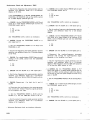
Theory of Operation.--7138'7
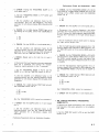
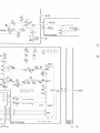
to EXT/AQR, S645 grounds the enable line and stops the
oscillator .
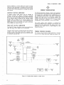
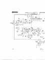
FIRST DIVIDER
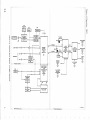
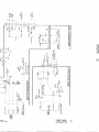
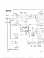
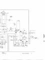
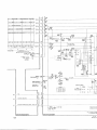
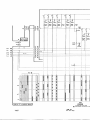
The First Divider (FD) receives the reference frequency
from the oscillator and divides it to form five subfrequencies (10 .24, 5.12, 2 .56, and 1 .28 MHz, and 512
kHz) . The FD consists of U635 and U636 .
Counter U635 receives the 20 .48-MHz reference
frequency on its A input and produces a half-frequency
output (10.24 MHz) . The 10 .24-MHz signal clocks
counter U636, which provides signals at one-half (5 .12
MHz) and one-fifth (2 .048 MHz) the 10 .24-MHz input
frequency.
The 2 .048-MHz output from U636 clocks U635's B input,
and U635 provides signals at one-half (1 .024 MHz) and
one-fourth (512 kHz) the 2.048-MHz input.
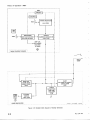
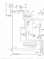
X1-X10 MULTIPLEXER
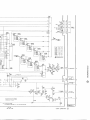
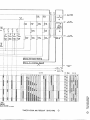
The X1-X10 Multiplexer selects the input frequency
designated by the levels on its A, B and C inputs . The
circuit consists of X1 multiplexer U638, X10 multiplexer
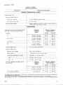
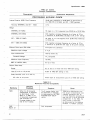
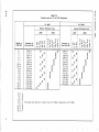
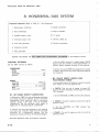
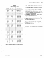
U637 and gate U621 D. Table 3-2 shows which inputs the
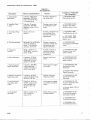
X1, X10 and Internal Clock multiplexers select for each
setting of the TIME/DIV control .
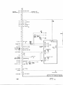
DECADE DIVIDER
The Decade Divider (DD) receives the output of the X1X10 Multiplexer, and from it provides five submultiple
frequencies to the Internal Clock Multiplexer . The DD
consists of counters U651, U652, U653 and U654 .
Counters U651, 0652 and U653 divide the output of the
X1-X10 Multiplexer and furnish the - 10, - 100, - 1 k,
10 k and = 100 k signals to the Internal Clock Multiplexer .
Counter U654 receives the - 10 signal from U653, and
divides it by 100 to form the Int _ 1000 input for the
output Clock Multiplexer .
INTERNAL CLOCK MULTIPLEXER
The Internal Clock Multiplexer receives the outputs of the
Decade Divider, and selects the one designated by the
outputs of the TIME/DIV switch as the Internal Clock.
One-of-sixteen multiplexer U660 is the Output Clock
Multiplexer . Table 3-2 shows which inputs U660 selects
for each setting of the TIME/DIV control .
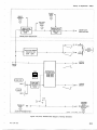
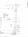
OUTPUT CLOCK MULTIPLEXER
The Output Clock Multiplexer receives the Internal Clock,
the Int - 1000 clock, and the Ext Clock signals and
selects one of them to be the output Clock signal .
Multiplexer U655, Q663, Q667 and 0671 form the
Output Multiplexer .
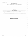
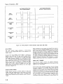
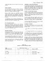
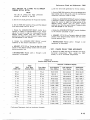
The AQS CLOCK/AQR switch, S645, controls pins 10
and 11 of U655, and causes U655 to select one of its
three inputs . Table 3-3 shows the three positions of
S645 and the resulting output of multiplexer U655 .
Transistors Q663, 0667 convert the TTL output of U655
to a level suitable for the mainframe.
INTENSIFY CIRCUIT
The Intensify circuit produces the Aux Z Axis signal,
which intensifies the display via the mainframe's z-axis
amplifier, when :
a. The '71387 is in the B Horiz plug-in compartment,
and
b. The Display B (pin 137) line is at a high-logic level.
If the Display B line is at a low-logic level when the 71387
is in the B Horiz plug-in compartment, or if the 71387 is in
the A Horiz plug-in compartment, the Intensify circuit
does not produce the Aux Z-Axis signal .
Although the 71387 is not called a "delaying" time base,
its "acquire stop" signal is identical to the Delay Gate in
a delaying time base, and its delay-mode operation is the
same . That is, the Delay Gate in the 71387 has two
functions- it sets the boundaries of the acquisition time
in a digitizing mainframe, such as the 7854, and operates
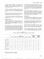
TABLE 3-3
Operation of Output Multiplexer U655
S645
AQS CLOCK/AQR
INTERNAL
__ , .._IN T
1000
EXT/AQR .
Output of U655
Internal Clock
Internal Clock = 1000
v External Clock
3- 1 5