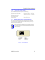
1
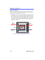
HSIM-F6 User’s Guide A B HSIM-F6 A B P S Only qualified personnel should perform installation procedures. NOTICE Cabletron Systems reserves the right to make changes in specifications and other information contained in this document without prior notice. The reader should in all cases consult Cabletron Systems to determine whether any such changes have been made. The hardware, firmware, or software described in this manual is subject to change without notice. IN NO EVENT SHALL CABLETRON SYSTEMS BE LIABLE FOR ANY INCIDENTAL, INDIRECT, SPECIAL, OR CONSEQUENTIAL DAMAGES WHATSOEVER (INCLUDING BUT NOT LIMITED TO LOST PROFITS) ARISING OUT OF OR RELATED TO THIS MANUAL OR THE INFORMATION CONTAINED IN IT, EVEN IF CABLETRON SYSTEMS HAS BEEN ADVISED OF, KNOWN, OR SHOULD HAVE KNOWN, THE POSSIBILITY OF SUCH DAMAGES. Copyright 1997 by Cabletron Systems, Inc., P.O. Box 5005, Rochester, NH 03866-5005 All Rights Reserved Printed in the United States of America Order Number: 9032091-03 September 1997 Cabletron Systems and LANVIEW are registered trademarks, HSIM and FPIM are trademarks of Cabletron Systems, Inc. All other product names mentioned in this manual may be trademarks or registered trademarks of their respective companies. FCC NOTICE This device complies with Part 15 of the FCC rules. Operation is subject to the following two conditions: (1) this device may not cause harmful interference, and (2) this device must accept any interference received, including interference that may cause undesired operation. NOTE: This equipment has been tested and found to comply with the limits for a Class A digital device, pursuant to Part 15 of the FCC rules. These limits are designed to provide reasonable protection against harmful interference when the equipment is operated in a commercial environment. This equipment uses, generates, and can radiate radio frequency energy and if not installed in accordance with the operator’s manual, may cause harmful interference to radio communications. Operation of this equipment in a residential area is likely to cause interference in which case the user will be required to correct the interference at his own expense. WARNING: Changes or modifications made to this device which are not expressly approved by the party responsible for compliance could void the user’s authority to operate the equipment. Printed on HSIM-F6 User’s Guide Recycled Paper i Notice DOC NOTICE This digital apparatus does not exceed the Class A limits for radio noise emissions from digital apparatus set out in the Radio Interference Regulations of the Canadian Department of Communications. Le présent appareil numérique n’émet pas de bruits radioélectriques dépassant les limites applicables aux appareils numériques de la class A prescrites dans le Règlement sur le brouillage radioélectrique édicté par le ministère des Communications du Canada. VCCI NOTICE This is a Class A product based on the standard of the Voluntary Control Council for Interference by Information Technology Equipment (VCCI). If this equipment is used in a domestic environment, radio disturbance may arise. When such trouble occurs, the user may be required to take corrective actions. CABLETRON SYSTEMS, INC. PROGRAM LICENSE AGREEMENT IMPORTANT: Before utilizing this product, carefully read this License Agreement. This document is an agreement between you, the end user, and Cabletron Systems, Inc. (“Cabletron”) that sets forth your rights and obligations with respect to the Cabletron software program (the “Program”) contained in this package. The Program may be contained in firmware, chips or other media. BY UTILIZING THE ENCLOSED PRODUCT, YOU ARE AGREEING TO BECOME BOUND BY THE TERMS OF THIS AGREEMENT, WHICH INCLUDES THE LICENSE AND THE LIMITATION OF WARRANTY AND DISCLAIMER OF LIABILITY. IF YOU DO NOT AGREE TO THE TERMS OF THIS AGREEMENT, PROMPTLY RETURN THE UNUSED PRODUCT TO THE PLACE OF PURCHASE FOR A FULL REFUND. ii HSIM-F6 User’s Guide Notice CABLETRON SOFTWARE PROGRAM LICENSE 1. LICENSE. You have the right to use only the one (1) copy of the Program provided in this package subject to the terms and conditions of this License Agreement. You may not copy, reproduce or transmit any part of the Program except as permitted by the Copyright Act of the United States or as authorized in writing by Cabletron. 2. OTHER RESTRICTIONS. You may not reverse engineer, decompile, or disassemble the Program. 3. APPLICABLE LAW. This License Agreement shall be interpreted and governed under the laws and in the state and federal courts of New Hampshire. You accept the personal jurisdiction and venue of the New Hampshire courts. EXCLUSION OF WARRANTY AND DISCLAIMER OF LIABILITY 1. EXCLUSION OF WARRANTY. Except as may be specifically provided by Cabletron in writing, Cabletron makes no warranty, expressed or implied, concerning the Program (including its documentation and media). CABLETRON DISCLAIMS ALL WARRANTIES, OTHER THAN THOSE SUPPLIED TO YOU BY CABLETRON IN WRITING, EITHER EXPRESSED OR IMPLIED, INCLUDING BUT NOT LIMITED TO IMPLIED WARRANTIES OF MERCHANTABILITY AND FITNESS FOR A PARTICULAR PURPOSE, WITH RESPECT TO THE PROGRAM, THE ACCOMPANYING WRITTEN MATERIALS, AND ANY ACCOMPANYING HARDWARE. 2. NO LIABILITY FOR CONSEQUENTIAL DAMAGES. IN NO EVENT SHALL CABLETRON OR ITS SUPPLIERS BE LIABLE FOR ANY DAMAGES WHATSOEVER (INCLUDING, WITHOUT LIMITATION, DAMAGES FOR LOSS OF BUSINESS, PROFITS, BUSINESS INTERRUPTION, LOSS OF BUSINESS INFORMATION, SPECIAL, INCIDENTAL, CONSEQUENTIAL, OR RELIANCE DAMAGES, OR OTHER LOSS) ARISING OUT OF THE USE OR INABILITY TO USE THIS CABLETRON PRODUCT, EVEN IF CABLETRON HAS BEEN ADVISED OF THE POSSIBILITY OF SUCH DAMAGES. BECAUSE SOME STATES DO NOT ALLOW THE EXCLUSION OR LIMITATION OF LIABILITY FOR CONSEQUENTIAL OR INCIDENTAL DAMAGES, OR ON THE DURATION OR LIMITATION OF IMPLIED WARRANTIES, IN SOME INSTANCES THE ABOVE LIMITATIONS AND EXCLUSIONS MAY NOT APPLY TO YOU. UNITED STATES GOVERNMENT RESTRICTED RIGHTS The enclosed product (a) was developed solely at private expense; (b) contains “restricted computer software” submitted with restricted rights in accordance with Section 52227-19 (a) through (d) of the Commercial Computer Software - Restricted Rights Clause and its successors, and (c) in all respects is proprietary data belonging to Cabletron and/or its suppliers. For Department of Defense units, the product is licensed with “Restricted Rights” as defined in the DoD Supplement to the Federal Acquisition Regulations, Section 52.227-7013 (c) (1) (ii) and its successors, and use, duplication, disclosure by the Government is subject to restrictions as set forth in subparagraph (c) (1) (ii) of the Rights in Technical Data and Computer Software clause at 252.227-7013. Cabletron Systems, Inc., 35 Industrial Way, Rochester, New Hampshire 03867-0505. HSIM-F6 User’s Guide iii Notice SAFETY INFORMATION CLASS 1 LASER TRANSCEIVERS THE FE-100F3 FAST ETHERNET INTERFACE MODULE, FPIM-05 AND FPIM-07 FDDI PORT INTERFACE MODULES, AND APIM-29 ATM PORT INTERFACE MODULE USE CLASS 1 LASER TRANSCEIVERS. READ THE FOLLOWING SAFETY INFORMATION BEFORE INSTALLING OR OPERATING THESE ADAPTERS. The Class 1 laser transceivers use an optical feedback loop to maintain Class 1 operation limits. This control loop eliminates the need for maintenance checks or adjustments. The output is factory set, and does not allow any user adjustment. Class 1 laser transceivers comply with the following safety standards: • 21 CFR 1040.10 and 1040.11 U.S. Department of Health and Human Services (FDA). • IEC Publication 825 (International Electrotechnical Commission). • CENELEC EN 60825 (European Committee for Electrotechnical Standardization). When operating within their performance limitations, laser transceiver output meets the Class 1 accessible emission limit of all three standards. Class 1 levels of laser radiation are not considered hazardous. SAFETY INFORMATION CLASS 1 LASER TRANSCEIVERS LASER RADIATION AND CONNECTORS When the connector is in place, all laser radiation remains within the fiber. The maximum amount of radiant power exiting the fiber (under normal conditions) is -12.6 dBm or 55 x 10-6 watts. Removing the optical connector from the transceiver allows laser radiation to emit directly from the optical port. The maximum radiance from the optical port (under worst case conditions) is 0.8 W cm-2 or 8 x 10³ W m2 sr-1. Do not use optical instruments to view the laser output. The use of optical instruments to view laser output increases eye hazard. When viewing the output optical port, power must be removed from the network adapter. iv HSIM-F6 User’s Guide Notice DECLARATION OF CONFORMITY Application of Council Directive(s): Manufacturer’s Name: Manufacturer’s Address: European Representative Name: European Representative Address: Conformance to Directive(s)/Product Standards: Equipment Type/Environment: 89/336/EEC 73/23/EEC Cabletron Systems, Inc. 35 Industrial Way PO Box 5005 Rochester, NH 03867 Mr. J. Solari Cabletron Systems Limited Nexus House, Newbury Business Park London Road, Newbury Berkshire RG13 2PZ, England EC Directive 89/336/EEC EC Directive 73/23/EEC EN 55022 EN 50082-1 EN 60950 Networking Equipment, for use in a Commercial or Light Industrial Environment. We the undersigned, hereby declare, under our sole responsibility, that the equipment packaged with this notice conforms to the above directives. Manufacturer Legal Representative in Europe Mr. Ronald Fotino ___________________________________ Full Name Mr. J. Solari ___________________________________ Full Name Principal Compliance Engineer ___________________________________ Title Managing Director - E.M.E.A. ___________________________________ Title Rochester, NH, USA ___________________________________ Location Newbury, Berkshire, England ___________________________________ Location HSIM-F6 User’s Guide v Notice vi HSIM-F6 User’s Guide CONTENTS CHAPTER 1 INTRODUCTION 1.1 Using This Manual....................................................................... 1-2 1.2 Document Conventions ............................................................... 1-2 1.3 Getting Help................................................................................. 1-3 1.4 Overview...................................................................................... 1-4 1.4.1 Features.......................................................................... 1-4 1.5 Specifications .............................................................................. 1-5 1.6 Related Documentation ............................................................... 1-6 CHAPTER 2 INSTALLATION 2.1 Unpacking the HSIM.................................................................... 2-1 2.2 Installing FPIMs ........................................................................... 2-2 2.3 Installing an HSIM ....................................................................... 2-4 2.3.1 Installing an HSIM in an Interface Module ...................... 2-4 2.3.2 Installing an HSIM in a Standalone Hub ......................... 2-7 CHAPTER 3 LOCAL MANAGEMENT 3.1 Local Management Keyboard Conventions................................. 3-2 3.1.1 Selecting Local Management Menu Screen Items ......... 3-3 3.1.2 Exiting Local Management Screens ............................... 3-3 3.2 Navigating Local Management Screens...................................... 3-4 3.3 The HSIM-F6 Setup Screen ........................................................ 3-4 3.4 The HSIM-F6 Statistics Screen ................................................... 3-7 3.4.1 HSIM-F6 Statistics Screen Fields ................................... 3-8 3.5 The MIB-II Statistics Screen ........................................................ 3-8 3.5.1 MIB-II Interface Statistics Screen Fields ......................... 3-9 3.6 The Ring Statistics Screen ........................................................ 3-10 3.6.1 HSIM-F6 FDDI Ring Statistics Screen Fields ............... 3-11 3.7 The Ring Map Configuration Screen ......................................... 3-16 3.7.1 Ring Map Configuration Screen Fields ......................... 3-17 3.7.2 Ring Map Configuration Screen Commands ................ 3-18 3.7.2.1 Adjusting the Scroll Number (n) ................... 3-18 3.7.3 The Node Information Screen....................................... 3-19 3.7.4 Node Information Screen Fields ................................... 3-20 3.8 The HSIM-F6 Configuration Screen .......................................... 3-21 3.8.1 HSIM-F6 Configuration Screen Fields .......................... 3-22 HSIM-F6 User’s Guide vii Contents 3.9 The Full Duplex Configuration Screen .......................................3-23 3.9.1 Full Duplex FDDI ...........................................................3-24 3.9.2 Full Duplex Configuration Screen Fields .......................3-25 3.9.3 Configuring the HSIM-F6 for Full Duplex Operation......3-26 3.10 The FDDI/Ethernet Translation Configuration Screen ...............3-27 3.10.1 FDDI Translation Configuration Screen Fields..............3-28 3.10.2 Setting Frame Translation Types ..................................3-30 3.10.3 Setting the Frame Translation Types to the Default Values .....................................................3-31 3.10.4 When to Set the Interpret 802.3 Length for Frames > 64 Bytes Field to [ENABLED] ..................3-31 3.10.5 Setting the Interpret 802.3 Length Field to [ENABLED].......................................................3-31 CHAPTER 4 LANVIEW LEDs 4.1 HSIM-F6 LED State Definitions ...................................................4-3 CHAPTER 5 SPECIFICATIONS 5.1 Fiber Optic Interface ....................................................................5-1 5.1.1 Multimode Specifications.................................................5-1 5.1.2 Single Mode Specifications .............................................5-2 5.2 Unshielded Twisted Pair (UTP) Specifications ............................5-4 5.3 Shielded Twisted Pair (STP) Transmitter Specifications .............5-5 5.4 Cable Specifications ....................................................................5-6 5.4.1 Multimode Fiber Optic Cable Length...............................5-6 5.4.2 Single Mode Fiber Optic Cable Length ...........................5-6 5.4.3 Twisted Pair Cable Length ..............................................5-7 5.5 Twisted Pair Pinout Configuration................................................5-7 APPENDIX A FPIM SPECIFICATIONS A.1 FPIM-00 and FPIM-01 ................................................................ A-1 A.2 FPIM-02 and FPIM-04 ................................................................ A-2 A.3 FPIM-05 and FPIM-07 ................................................................ A-3 viii HSIM-F6 User’s Guide CHAPTER 1 INTRODUCTION Welcome to the Cabletron Systems HSIM-F6 User’s Guide. This manual provides the following information: • Describes HSIM-F6 features. • Explains how to install the HSIM-F6 in a Cabletron Systems interface module or standalone hub. • Explains how to configure and monitor the HSIM-F6 through Local Management. • Outlines specifications for the Cabletron Systems Fiber Distributed Data Interface (FDDI) High Speed Interface Module (HSIM). The HSIM-F6 provides additional connectivity/functionality to various Cabletron Systems interface modules and standalone hubs through the use of FDDI technology. In addition to having a general working knowledge of Ethernet and IEEE 802.3 type data communications networks and their physical layer components, you should also understand FDDI networks and the ANSI X3T9.5 standard prior to installing the HSIM-F6. The HSIM-F6, shown in Figure 1-1, uses two FPIM (FDDI Port Interface Module) slots to provide the option of using multimode fiber optic, single mode fiber optic, unshielded twisted pair, or shielded twisted pair transceiver ports based on the network requirements. A B HSIM-F6 A B P S 209100 Figure 1-1 HSIM-F6 User’s Guide The HSIM-F6 1-1 Chapter 1: Introduction 1.1 USING THIS MANUAL Read through this manual completely to familiarize yourself with its content and to gain an understanding of the features and capabilities of the HSIM-F6. The following list provides an overview of each section of this manual: Chapter 1, Introduction, outlines the contents of this manual, describes the HSIM-F6 features and concludes with a list of related manuals. Chapter 2, Installation, describes how to install FDDI Port Interface Modules (FPIMs) into the HSIM-F6. This chapter also explains how to install an HSIM-F6 into an interface module or a standalone hub. Chapter 3, Local Management, describes how to use the HSIM-F6 Local Management screens to set up FDDI Full Duplex connections, set FDDI to Ethernet frame translation parameters and to view the HSIM-F6 and FDDI ring statistics. Chapter 4, LANVIEW LEDs, describes how to use the HSIM-F6 LEDs to monitor the HSIM performance and status. Chapter 5, Specifications, lists the operating and cabling specifications of the HSIM-F6 for the variety of physical interfaces that can be used. Appendix A, FPIM Specifications, describes specifications and features for each of the FPIMs available for the HSIM-F6. 1.2 DOCUMENT CONVENTIONS The following conventions are used throughout this document: NOTE ! Note symbol. Calls the reader’s attention to any item of information that may be of special importance. Caution symbol. Contains information essential to avoid damage to the equipment. CAUTION Electrical Hazard Warning symbol. Warns against an action that could result in personal injury or death due to an electrical hazard. 1-2 HSIM-F6 User’s Guide Getting Help 1.3 GETTING HELP If you need additional support related to this device, or if you have any questions, comments, or suggestions concerning this manual, contact the Cabletron Systems Global Call Center: Phone (603) 332-9400 Internet mail [email protected] FTP Login Password ctron.com (134.141.197.25) anonymous your email address Modem setting (603) 335-3358 8N1: 8 data bits, No parity, 1 stop bit BBS For additional information about Cabletron Systems or our products, visit our World Wide Web site: http://www.cabletron.com/ For technical support, select Service and Support. Before calling the Cabletron Systems Global Call Center, have the following information ready: • Your Cabletron Systems service contract number • A description of the failure • A description of any action(s) already taken to resolve the problem (e.g., changing mode switches, rebooting the unit, etc.) • The serial and revision numbers of all involved Cabletron Systems products in the network • A description of your network environment (layout, cable type, etc.) • Network load and frame size at the time of trouble (if known) • The device history (i.e., have you returned the device before, is this a recurring problem, etc.) • Any previous Return Material Authorization (RMA) numbers HSIM-F6 User’s Guide 1-3 Chapter 1: Introduction 1.4 OVERVIEW The HSIM-F6 extends the functionality of certain Cabletron Systems interface modules or standalone hubs to include high-speed uplink capability. The HSIM-F6 allows remote connectivity using FDDI technology. 1.4.1 Features Connectivity The HSIM-F6 is equipped with slots for FDDI A and B ports. These two ports allow connection to the ring as a Dual Attached Station (DAS) using two FPIMs or as a Single Attached Station (SAS) using one FPIM. As a DAS, the module or standalone hub that houses the HSIM-F6 connects directly to the FDDI primary ring. This provides the reliability of an FDDI dual, counter-rotating ring topology. If one segment of the FDDI ring becomes disabled, this dual ring configuration provides redundancy and restores ring continuity. As a SAS, the HSIM-F6 connects to the primary ring only by using a single FPIM on the HSIM-F6 to attach to the M port of an FDDI concentrator. The HSIM-F6 also supports dual homing. A dual homing configuration provides additional redundancy for the module or hub containing the HSIM-F6. Dual homing is a way of connecting to an FDDI ring through the Master (M type) ports of two separate dual attached concentrators. If one M type port or one segment fails, the redundant port or segment activates automatically to retain connection to the ring. The HSIM-F6 is also capable of operating in full duplex mode, which creates a point-to-point link between two FDDI devices. This allows for a data rate of 200 Mbps, with each device transmitting and receiving at 100 Mbps simultaneously. Chapter 3, Local Management, provides instructions on configuring the HSIM-F6 to operate in full duplex mode. Bridging The HSIM-F6 provides translational bridging between any channels or ports in its host module or hub and the FDDI ring. 1-4 HSIM-F6 User’s Guide Specifications LANVIEW Diagnostic LEDs Cabletron Systems provides a visual diagnostic and monitoring system called LANVIEW. The HSIM-F6 LANVIEW LEDs help you quickly identify transmit/receive, link, and FDDI ring status. Chapter 4, LANVIEW LEDs, provides information on all HSIM-F6 LEDs. 1.5 SPECIFICATIONS This section describes environment specifications and safety requirements for the HSIM-F6. Cabletron Systems reserves the right to change these specifications at any time without notice. Environment Operating Temperature: 5°C to 40°C (41°F to 104°F) Storage Temperature: -30°C to 73°C (-22°F to 164°F) Operating Relative Humidity: 5% to 90% (non-condensing) Regulatory Compliance Safety: Electromagnetic Compatibility (EMC): HSIM-F6 User’s Guide UL 1950, CSA C22.2 No. 950, EN 60950, IEC 950, and 73/23/EEC FCC Part 15, VCCI V-3, EN 55022, CSA C108.8, EN 50082-1, 89/336/EEC AS/NZS 3548 1-5 Chapter 1: Introduction 1.6 RELATED DOCUMENTATION Use the following manuals to supplement the procedures and other technical data provided in this manual. This manual references procedures in these manuals, where appropriate, but does not repeat them. Cabletron Systems Cabling Guide Cabletron Systems FDDI Technology Guide NOTE The documentation for the device in which the HSIM-F6 will be installed may assist you with the installation and setup of the HSIM-F6. The manuals referenced above can be obtained on the World Wide Web in Adobe Acrobat Portable Document Format (PDF) at the following site: http://www.cabletron.com/ These manuals are also available on the Cabletron Systems Hardware Manuals CD-ROM. 1-6 HSIM-F6 User’s Guide CHAPTER 2 INSTALLATION This chapter contains instructions for the following items: • Unpacking the HSIM (Section 2.1) • Installing FPIMs (Section 2.2) • Installing an HSIM (Section 2.3) To install the HSIM and FPIMs, you need the following items: • Antistatic wrist strap (provided with 6C105 chassis or standalone hub) • Phillips screwdriver ! CAUTION 2.1 The HSIM-F6 and the host module or hub are sensitive to static discharges. Use a grounding strap and observe all static precautions during this procedure. Failure to do so could result in damage to the HSIM-F6, host module or hub. UNPACKING THE HSIM Unpack the HSIM as follows: 1. Remove the shipping box material covering the HSIM. 2. Carefully remove the module from the shipping box. Leave the module in its non-conductive bag until you are ready to install it. 3. Attach the antistatic wrist strap. If the HSIM is to be installed in a standalone hub, refer to the instructions on the antistatic wrist strap package. If the HSIM is to be installed in an interface module, refer to the applicable interface module User’s Guide. 4. After removing the module from its non-conductive bag, visually inspect the device. If you notice any signs of damage, contact Cabletron Systems Global Call Center immediately. Refer to Section 1.3, Getting Help, for instructions. HSIM-F6 User’s Guide 2-1 Chapter 2: Installation 2.2 INSTALLING FPIMs Only qualified personnel should install or service this unit. ! CAUTION The HSIM-F6 and FPIMs are sensitive to static discharges. Use a grounding strap and observe all static precautions during this procedure. Failure to do so could result in damage to the HSIM-F6 or the FPIMs. To install an FPIM into the HSIM-F6, perform the following steps: 1. Attach the antistatic wrist strap. If the HSIM is to be installed in a standalone hub, refer to the instructions on the antistatic wrist strap package. If the HSIM is to be installed in an interface module, refer to the applicable interface module User’s Guide. 2. Refer to Figure 2-1 and remove the two screws from the standoffs. The two screws secure the FPIM coverplate. Save the screws and remove the FPIM coverplate. 3. Refer to Figure 2-2 and remove the three faceplate screws attaching the faceplate to the HSIM-F6. Save the screws. ! CAUTION When mating the FPIM connector to the HSIM pins, take extra care that the pins do not enter the connector at an angle to avoid damaging both the FPIM connector and the HSIM pins. 4. Press the FPIM connector into the HSIM pins. 2-2 HSIM-F6 User’s Guide Installing FPIMs Standoff Screws FPIM Coverplate HSIM Standoffs Figure 2-1 Removing the FPIM Coverplate FPIM Screws FPIM Connector A HSIM FPIM Connector Pins B HSIM Faceplate Screws HS IM -F A P 6 B S Standoffs 209134 Figure 2-2 HSIM-F6 User’s Guide Installing FPIMs 2-3 Chapter 2: Installation 5. Press down firmly on the FPIM until the pins slide all the way into the HSIM connector. 6. Secure the FPIM with the screws saved in step 2. 7. Secure the faceplate of the HSIM with the screws saved in step 3. 2.3 INSTALLING AN HSIM Only qualified personnel should install or service this unit. You can install an HSIM in any Cabletron Systems device that supports HSIM technology (e.g., 2E42-27, 6E132-25). Refer to the release notes for the version of firmware running on the Cabletron Systems device to ensure that the HSIM-F6 is supported. The following subsections provide generic instructions for installing an HSIM-F6 in an interface module or in a standalone hub. Refer to your specific interface module or standalone hub documentation for exact HSIM slot and connector locations. 2.3.1 ! CAUTION Installing an HSIM in an Interface Module The HSIM-F6 and the host module or standalone hub are sensitive to static discharges. Use an antistatic wrist strap and observe all static precautions during this procedure. Failure to do so could result in damage to the HSIM-F6, the host module or standalone hub. To install an HSIM-F6 in an interface module that supports HSIM technology perform the following steps. 1. Note the ports of the interface module that have cables attached to them. Then disconnect those cables from the ports. 2. Attach the antistatic wrist strap (refer to the instructions outlined in the interface module User’s Guide). 3. Unlock the top and bottom plastic locking tabs of the module faceplate. 2-4 HSIM-F6 User’s Guide Installing an HSIM 4. Slide out the module, and place it on its side with the internal components facing up. 5. Refer to Figure 2-3 and remove the two faceplate mounting screws and the HSIM coverplate. Save the screws. 6. Refer to Figure 2-3 and remove the two standoff screws. Save the screws. Standoff Screws Coverplate Faceplate Mounting Screws 209135 Figure 2-3 Removing the HSIM Coverplate 7. Refer to Figure 2-4 and place the HSIM behind the module faceplate. 8. Align the HSIM connector of the HSIM-F6 into the HSIM pins on the module. HSIM-F6 User’s Guide 2-5 Chapter 2: Installation 9. Press down firmly on the back of the HSIM until the pins slide all the way into the HSIM Connector. NOTE Ensure that the standoffs on the interface module align with the standoff screw holes on the HSIM. 10. Secure the HSIM-F6 to the module faceplate using the mounting screws saved in step 5. 11. Secure the HSIM-F6 to the module standoffs using the standoff screws saved in step 6. 12. Reinstall the module in the chassis. 13. Reattach the network cabling to the module. Refer to Chapter 3 for instructions on configuring the HSIM-F6 using Local Management. 2-6 HSIM-F6 User’s Guide Installing an HSIM Standoff Screws HSIM Connector HSIM A Pins B A P B S Faceplate Mounting Screws Standoffs 225705 Figure 2-4 2.3.2 Installing the HSIM-F6 Installing an HSIM in a Standalone Hub To install an HSIM-F6 into a standalone hub (e.g. 2E42-27), perform the following steps: 1. Power down the hub and remove the power cord. 2. Note the ports that have cables attached to them. Then disconnect those cables from the ports. To install the HSIM-F6 in a standalone hub the device MUST be powered down. Ensure that you remove the power cord and ONLY the screws required to remove the chassis cover. Failure to comply could result in an electric shock hazard. HSIM-F6 User’s Guide 2-7 Chapter 2: Installation 3. Attach the antistatic wrist strap (refer to the instructions outlined on the antistatic wrist strap package). 4. Remove the hub chassis cover (refer to your specific hub documentation for instructions on removing the hub chassis cover). 5. Refer to Figure 2-3 and remove the two faceplate mounting screws and the HSIM coverplate. Save the screws. 6. Refer to Figure 2-3 and remove the two standoff screws. Save the screws. 7. Place the HSIM behind the hub faceplate. 8. Align the HSIM connector of the HSIM with the pins on the hub. 9. Press down firmly on the back of the HSIM until the pins slide all the way into the HSIM connector holes. NOTE Ensure that the standoffs on the hub align with the standoff screw holes on the HSIM. 10. Secure the HSIM-F6 to the module faceplate using the mounting screws saved in step 5. 11. Secure the HSIM-F6 to the module standoffs using the standoff screws saved in step 6. Ensure that the chassis cover is in place before reconnecting the power cord. 12. Reattach the chassis cover to the hub, reconnect the power cord, and reconnect the hub to the network. Refer to Chapter 3 for instructions on configuring the HSIM-F6 using Local Management. 2-8 HSIM-F6 User’s Guide CHAPTER 3 LOCAL MANAGEMENT This chapter provides instructions on configuring the HSIM-F6 to operate in full duplex FDDI mode, viewing HSIM-F6 FDDI statistics, translating specific FDDI frame types to specific Ethernet frame types and to viewing the FDDI ring topology using Local Management. NOTE When installed, the HSIM-F6 provides additional Local Management features. These features are accessed by entering Local Management of the host interface module or standalone hub. Refer to the host device User’s Guide to establish a Local Management connection. Make sure that the following requirements have been met before configuring the HSIM-F6 through Local Management: • At least one FPIM is installed in the HSIM-F6. • The HSIM-F6 is installed in the host interface module or standalone hub. • The device is up and running. • A Local Management terminal is properly configured and connected to the host interface module or standalone hub in which the HSIM-F6 resides. NOTE If the HSIM-F6 is being configured to operate in full duplex mode, two FPIMs must be installed before proceeding. To view HSIM-F6 FDDI statistics and ring topology, the HSIM-F6 must be connected to the FDDI ring. HSIM-F6 User’s Guide 3-1 Chapter 3: Local Management 3.1 LOCAL MANAGEMENT KEYBOARD CONVENTIONS All key names appear in this manual as capital letters. For example, the Enter key appears as ENTER and the Backspace key appears as BACKSPACE. Table 3-1 explains the keyboard conventions used in this manual as well as the key functions. Table 3-1 Keyboard Conventions Key Function ENTER Key and RETURN Key These are selection keys that perform the same Local Management function. For example, “Press ENTER” means that you can press either ENTER or RETURN, unless this manual specifically instructs you otherwise. SPACE Bar and BACKSPACE Key These keys cycle through selections in some Local Management fields. Use the SPACE bar to cycle forward through selections and use BACKSPACE to cycle backward through selections. Arrow Keys These are navigation keys. Use the UP-ARROW, DOWN-ARROW, LEFT-ARROW, and RIGHT-ARROW keys to move the screen cursor. For example, “Use the arrow keys” means to press whichever arrow key moves the cursor to the desired field on the Local Management screen. 3-2 HSIM-F6 User’s Guide Local Management Keyboard Conventions 3.1.1 Selecting Local Management Menu Screen Items Select items on a menu screen by performing the following steps: 1. Use the arrow keys to highlight a menu item. 2. Press ENTER. The selected menu item displays on the screen. 3.1.2 Exiting Local Management Screens Exit Local Management using the methods described below: Using the EXIT Command To exit an LM screen using the EXIT command, proceed as follows: 1. Use the arrow keys to highlight the EXIT command at the bottom of the Local Management Screen. 2. Press ENTER. The Password screen displays and the session ends. Using the RETURN Command 1. Use the arrow keys to highlight the RETURN command at the bottom of the Local Management screen. 2. Press ENTER. The previous screen in the Local Management hierarchy displays. NOTE The user can also exit Local Management screens by pressing ESC twice. This exit method does not warn about unsaved changes and all unsaved changes will be lost. 3. Exit from Local Management by repeating steps 1 and 2 until the Main Menu screen displays. 4. Use the arrow keys to highlight the RETURN command at the bottom of the Main Menu screen. 5. Press ENTER. The Password screen displays and the session ends. HSIM-F6 User’s Guide 3-3 Chapter 3: Local Management 3.2 NAVIGATING LOCAL MANAGEMENT SCREENS The HSIM-F6 Local Management application consists of a series of menu screens. Navigate through Local Management by selecting items from the menu screens. Figure 3-1 shows the hierarchy of the HSIM-F6 Local Management screens. MIB-II Statistics Ring Statistics (Standalone Hub View) High Speed Configuration HSIM HSIM-F6 Statistics HSIM-F6 High Speed (Interface Module View) Configuration Ring Map Configuration Ring Map Node HSIM-F6 Configuration Full Duplex Configuration FDDI/Ethernet Translation Configuration Figure 3-1 3.3 HSIM-F6 Local Management Hierarchy THE HSIM-F6 SETUP SCREEN To access the HSIM-F6 Setup screen in a standalone hub (e.g., 2E42-27), navigate through the Local Management screens until the High Speed Configuration screen displays. Select HSIM from the High Speed Configuration screen and press ENTER. The HSIM-F6 Setup screen displays. See Figure 3-2. To access the HSIM-F6 Setup screen from an interface module (e.g., 6E132-25), navigate through the Local Management screens until the Module Specific Configuration Menu screen displays. Select HIGH SPEED CONFIGURATION from the Module Specific Configuration Menu screen and press ENTER. The HSIM-F6 Setup screen displays. See Figure 3-2. 3-4 HSIM-F6 User’s Guide The HSIM-F6 Setup Screen Device Name: 6E132-25 Slot Number: X Flash Image Revision: XX.XX.XX BOOTPROM Revision: XX.XX.XX HSIM-F6 HSIM-F6 Statistics Ring Map Configuration HSIM-F6 Configuration Full Duplex Configuration FDDI/Ethernet Translation Configuration EXIT RETURN 209109 Figure 3-2 The HSIM-F6 Setup Screen The HSIM-F6 Setup screen displays five menu items for accessing Local Management screens that allow further configuring and monitoring of the HSIM-F6 and the FDDI ring. The following list explains each of the HSIM-F6 Setup screen menu items: HSIM-F6 Statistics Select this menu item to display the HSIM-F6 Statistics screen. This screen allows the user to open screens that display the current HSIM-F6 FDDI Ring operational status and MIB-II interface statistics. Ring Map Configuration Select this menu item to display the Ring Map Configuration screen. The Ring Map Configuration screen contains configuration and connection information and displays the topology of the FDDI ring to which the HSIM-F6 is connected. The Ring Map Configuration screen also provides information on all nodes attached to the FDDI ring. HSIM-F6 User’s Guide 3-5 Chapter 3: Local Management HSIM-F6 Configuration Select this menu item to display the HSIM-F6 Configuration screen. This screen allows the user to view the operating requirements that the HSIM-F6 advertises to all other stations when it first enters the FDDI ring and to set the interval that the HSIM-F6 sends Neighbor Information Frames (NIFs). Full Duplex Configuration Select this menu item to display the Full Duplex Configuration screen. This screen allows the user to configure the HSIM-F6 to operate in full duplex mode. FDDI/Ethernet Translation Configuration Select this menu item to display the FDDI/Ethernet Translation Configuration screen. This screen allows the user to assign specific FDDI to Ethernet frame translations. 3-6 HSIM-F6 User’s Guide The HSIM-F6 Statistics Screen 3.4 THE HSIM-F6 STATISTICS SCREEN To access the HSIM-F6 Statistics screen from the HSIM-F6 Setup screen, perform the following steps: 1. Use the arrow keys to highlight the HSIM-F6 Statistics menu item on the HSIM-F6 Setup screen. 2. Press ENTER. The HSIM-F6 Statistics screen, Figure 3-3, displays. Device Name: 6E132-25 Slot Number: X Flash Image Revision: XX.XX.XX BOOTPROM Revision: XX.XX.XX HSIM-F6 Statistics MIB-II STATISTICS RING STATISTICS EXIT RETURN 209141 Figure 3-3 HSIM-F6 User’s Guide The HSIM-F6 Statistics Screen 3-7 Chapter 3: Local Management 3.4.1 HSIM-F6 Statistics Screen Fields The HSIM-F6 Statistics screen allows the user to open screens that display the current HSIM-F6 operational status. The definitions for the HSIM-F6 Statistics screen menu items are as follows: MIB-II STATISTICS When selected, this menu item opens the MIB-II Interface Statistics screen. RING STATISTICS When selected, this menu item opens the Ring Statistics screen. 3.5 THE MIB-II STATISTICS SCREEN To view the MIB-II interface statistics, use the arrow keys to highlight the MIB-II STATISTICS menu item on the HSIM-F6 Statistics screen and press ENTER. The MIB-II Interface Statistics screen, Figure 3-4, displays. Device Name: 6E132-25 Slot Number: X Flash Image Revision: XX.XX.XX BOOTPROM Revision: XX.XX.XX HSIM-F6 STATISTICS MIB-II INTERFACE IN OCTETS: IN UNICAST PKTS: IN NONUCAST PKTS: IN DISCARDS: IN ERRORS: 106191454 643007 201452 0 5 OUT OCTETS: OUT UNICAST PKTS: OUT NONUCAST PKTS: OUT DISCARDS: OUT ERRORS: 967271 6626 38 0 0 CLEAR COUNTERS EXIT RETURN 209144 Figure 3-4 3-8 The MIB-II Interface Statistics Screen HSIM-F6 User’s Guide The MIB-II Statistics Screen 3.5.1 MIB-II Interface Statistics Screen Fields The following list describes the MIB-II Statistics screen fields: IN OCTETS This field displays the number of octets (bytes) received by the HSIM-F6. IN UNICAST PKTS This field displays the number of unicast packets (packets destined for one specific address) received by the HSIM-F6. IN NONUCAST PKTS This field displays the number of non-unicast packets (multicast and broadcast packets: packets destined for more than one address) received by the HSIM-F6. IN DISCARDS This field displays the total number of packets discarded by the HSIM-F6 due to lack of available resources. IN ERRORS This field displays the total number of errors (of any type) received by the HSIM-F6. OUT OCTETS This field displays the number of octets (bytes) transmitted by the HSIM-F6. OUT UNICAST PKTS This field displays the number of unicast packets (packets destined for one specific address) transmitted by the HSIM-F6. OUT NONUCAST PKTS This field displays the number of non-unicast packets (multicast and broadcast packets: packets destined for more than one address) transmitted by the HSIM-F6. OUT DISCARDS This field displays the total number of packets discarded by the HSIM-F6 due to a lack of available resources. HSIM-F6 User’s Guide 3-9 Chapter 3: Local Management OUT ERRORS This field displays the total number of errors (of any type) transmitted by the HSIM-F6. CLEAR COUNTERS The Clear Counters command resets all counters within the MIB-II Statistics screen to zero. To reset all the counters use the arrow keys to highlight the CLEAR COUNTERS field and press ENTER. The counters are now reset to zero. 3.6 THE RING STATISTICS SCREEN To view the Ring statistics, use the arrow keys to highlight the RING STATISTICS menu item on the HSIM-F6 Statistics screen and press ENTER. The HSIM-F6 FDDI Ring Statistics screen, Figure 3-5, displays. Device Name: 6E132-25 Slot Number: X Flash Image Revision: XX.XX.XX BOOTPROM Revision: XX.XX.XX HSIM-F6 FDDI Ring Statistics RING STATE RING-OP COUNT MAC CONFIGURATION Tneg Tnotify MASTER PORT COUNT RING-OP 1 THROUGH-A 6 30 0 EXIT RETURN 209108 Figure 3-5 3-10 The HSIM-F6 FDDI Ring Statistics Screen HSIM-F6 User’s Guide The Ring Statistics Screen 3.6.1 HSIM-F6 FDDI Ring Statistics Screen Fields The HSIM-F6 FDDI Ring Statistics screen allows the user to monitor the current HSIM-F6 operational status. The following list describes the Ring Statistics screen fields: RING STATE Displays the current ring state. The possible ring states are as follows: • Ring-Op - The ring is functioning correctly. • Isolated - The HSIM-F6 is not attached to the ring. • Non-Op - The HSIM-F6 is attempting to enter the ring. • Detect - The claim (beacon) process of the FDDI ring protocol has exceeded one second. There may be a problem. • Non-Op-Dup - The ring failed to complete the claim (beacon) process. This usually indicates a duplicate FDDI address. • Ring-Op-Dup - The ring is operational, but a duplicate FDDI address may be present somewhere on the network. • Directed - The claim (beacon) process did not complete within ten seconds. The HSIM-F6 is sending directed beacons to indicate a problem. • Trace - A problem has been detected with the HSIM-F6 or the nearest active upstream neighbor (NAUN). A trace is being sent to notify the nearest active upstream neighbor of the problem. RING-OP COUNT The Ring-Op Count keeps track of the number of times the FDDI ring has initialized since the last time the HSIM-F6 (or host device in which it resides) was reset. If this number grows steadily over a brief period of time, it signifies the ring is unstable. HSIM-F6 User’s Guide 3-11 Chapter 3: Local Management MAC CONFIGURATION The MAC Configuration field describes the current configuration of the Media Access Control (MAC) and physical layers of the A and B ports. The possible port configurations are as follows: • Through-A - The flow of the primary ring is entering the MAC from port A (primary ring in) and exiting through port B (primary ring out). The secondary ring is isolated from the MAC with the flow entering from port B (secondary ring in) and exiting through port A (secondary ring out). In a normal ring state the HSIM-F6 MAC Configuration should read “Through-A”. Primary In Port A Secondary Out Figure 3-6 3-12 Primary Out MAC Port B Secondary In Example of Through-A MAC Configuration HSIM-F6 User’s Guide The Ring Statistics Screen • Wrap-A - The flow of the primary ring is entering through port A (primary in) and is wrapped by the MAC, causing the ring to exit through port A (secondary out). Port B is disconnected from the ring. If the HSIM-F6 MAC Configuration reads “Wrap-A” the ring has lost the redundancy of the secondary ring due to the wrapped condition. This configuration should be repaired, as additional problems could isolate stations from the FDDI ring. Primary In Port A Secondary Out Figure 3-7 HSIM-F6 User’s Guide Primary Out MAC Port B Secondary In Example of Wrap-A MAC Configuration 3-13 Chapter 3: Local Management • Wrap-B - The flow of the primary ring is entering through port B (secondary in) and is wrapped by the MAC, causing the ring to exit through port B (primary out). Port A is disconnected from the ring. If the HSIM-F6 MAC Configuration reads “Wrap-B” the ring has lost the redundancy of the secondary ring due to the wrapped condition. This configuration should be repaired, as additional problems could isolate stations from the FDDI ring. Primary In Port A Primary Out MAC Secondary In Secondary Out Figure 3-8 • Port B Example of Wrap-B MAC Configuration Isolated - Both port A and port B are isolated from the ring. Primary In Port A Secondary Out Figure 3-9 3-14 Primary Out MAC Port B Secondary In Example of Isolated MAC Configuration HSIM-F6 User’s Guide The Ring Statistics Screen • Wrap-AB - The flow of the primary ring is entering through port A (primary in) and is wrapped by the MAC, causing the ring to exit through port A (secondary out). The MAC has also wrapped port B, causing the flow of the ring to enter through port B (secondary in) and exit through port B (primary out). The HSIM-F6 MAC Configuration can read “Wrap-AB” if the HSIM-F6 is in a dual homed configuration. Primary In Primary Out Port A MAC Secondary In Secondary Out Figure 3-10 Port B Example of Wrap-AB MAC Configuration Tneg (Time Negotiated) The Tneg field displays the negotiated token rotation time (in milliseconds) that the devices on the ring established through the token claiming process. Tnotify The Tnotify field displays the interval (in seconds) at which the HSIM-F6 transmits Neighbor Information Frames (NIFs). The HSIM-F6 uses NIFs to periodically announce its address and basic station description. MASTER PORT COUNT The Master Port Count field displays the number of available M type ports. HSIM-F6 User’s Guide 3-15 Chapter 3: Local Management 3.7 THE RING MAP CONFIGURATION SCREEN The Ring Map Configuration screen displays FDDI formatted addresses of ring stations in a graphic illustration of the FDDI ring topology, and provides access to a Node Information screen for each device located on the ring. To access the Ring Map Configuration screen from the HSIM-F6 Setup screen, perform the following steps: 1. Use the arrow keys to highlight the Ring Map Configuration menu item on the HSIM-F6 Setup screen. 2. Press ENTER. The Ring Map Configuration screen, Figure 3-11, displays. Device Name: 6E132-25 Slot Number: X Flash Image Revision: XX.XX.XX BOOTPROM Revision: XX.XX.XX Ring Map Configuration FDDI Address: 00:00: B8: 08: F9: C4 Current Ring Map: Primary MAC Count: 3 Address Mode: [MAC] 00: 00: B8: 08: F9: C4 (DAS) <<<<<<<<<<<<<<<<<<<< 00: 00: B8: 08: F9: FA (DAC) >>>>>>>>>>>>>>>>>>>> SCROLL DOWN 1 SCROLL UP 1 (DAS) 00: 00: B8: 08: DB: 11 EXIT RETURN 209141 Figure 3-11 NOTE 3-16 The Ring Map Configuration Screen Under some conditions the display must remain on the screen for at least 30 seconds to accurately reflect ring configuration. A neighbor time-out can take as long as 228 seconds to update on the ring map. HSIM-F6 User’s Guide The Ring Map Configuration Screen 3.7.1 Ring Map Configuration Screen Fields The Ring Map Configuration screen displays the addresses and sequence of each FDDI device attached to the ring. When first displayed, the station at the upper left corner of the ring is this station (HSIM-F6). The Ring Map Configuration screen displays node class, node address, and twisted and/or wrapped conditions (T for twisted and/or W for wrapped) in parentheses. The following list provides the node class possibilities: NAS - (Null Attached Station) Isolated station; station not connected to an FDDI Ring. DAS - (Dual Attached Station) Station does not support M (Master) ports, but does connect directly to an FDDI primary and secondary ring using A and B ports. DAC - (Dual Attached Concentrator) Station that supports M (Master) ports and provides access for multiple stations. A DAC connects directly to an FDDI ring using A and B ports. SAS - (Single Attached Station) Station that accesses the primary ring only, via a concentrator. SAC - (Single Attached Concentrator) Station that accesses the primary ring only and provides access for multiple Single Attached Stations (SAS). Single Attached Concentrators provide the same services as DACs, but without the redundancy of the dual ring topology. NOTES While Local Management updates the ring map, for example, during a ring topology change, the screen displays ??-??-??-??-??-?? to illustrate an undetermined address. You cannot use the scroll commands until Local Management finishes rebuilding the map. The Ring Map display stops at the first occurrence of an undetermined address, and does not display any known information beyond this point. HSIM-F6 User’s Guide 3-17 Chapter 3: Local Management 3.7.2 Ring Map Configuration Screen Commands The following list describes each of the Ring Map Configuration screen commands: Address Mode [ ] The Address Mode command allows the user to switch between canonical and MAC format addresses. To toggle between the two address modes, press the SPACE bar. SCROLL DOWN n The Scroll Down n command rotates the ring display, so that the station addresses shift around the ring in a clockwise direction. The n controls the number of shifts downstream of the HSIM-F6. SCROLL UP n The Scroll Up n command rotates the ring display, so that the station addresses shift around the ring in a counterclockwise direction. The n controls the number of shifts upstream of the HSIM-F6. NOTE 3.7.2.1 When the ring map contains only one station, the SCROLL UP n and SCROLL DOWN n commands do not appear. Adjusting the Scroll Number (n) When using the SCROLL DOWN n or SCROLL UP n commands, the n allows the user to control the number of shifts made with each command execution. To set the number (n) of scrolls, perform the following steps: 1. Using the ARROW keys, highlight the SCROLL DOWN n or SCROLL UP n command. 2. Press the SHIFT and + keys (to increment) or the SHIFT and - keys (to decrement) until the number of shifts desired displays. 3. Press ENTER. The ring map scrolls n number of shifts. NOTE 3-18 The scroll number remains the same until it is changed manually, or the Local Management session is terminated. HSIM-F6 User’s Guide The Ring Map Configuration Screen 3.7.3 The Node Information Screen The Ring Map Node Information screen provides information for each selected node on the Ring Map Configuration screen. NOTE The Ring Map Node Information screen reflects node status at the time the node was selected. The Node Information screen does not change dynamically with network topology changes. To access the Node Information screen from the Ring Map Configuration screen, use the arrow keys to highlight any node (FDDI address) illustrated on the ring, and press ENTER. The Node Information screen, Figure 3-12, displays. Device Name: 6E132-25 Slot Number: X Flash Image Revision: XX.XX.XX BOOTPROM Revision: XX.XX.XX Ring Map NODE Selected Node Address: Upstream Address: Node Class: MAC Count: Non-Master Count: Master Count: Peer Wrap: Unattached Conc: Twisted A-A: Twisted B-B: Synchronous Service: Rooted: 00: 00: B8: 08: DB: 11 00: 00: B8: 08: F9: FA DAS 1 2 0 NO NO NO NO NO YES EXIT RETURN 209142 Figure 3-12 HSIM-F6 User’s Guide The Ring Map Node Information Screen 3-19 Chapter 3: Local Management 3.7.4 Node Information Screen Fields The following list describes each of the Node Information screen fields: Address Displays the address of the selected node. Upstream Address Displays the address of the selected node’s nearest active upstream neighbor (NAUN). Node Class Displays the class (NAS, DAS, DAC, SAS, or SAC) of the selected node. For an explanation of these class codes, refer to Section 3.7.1. MAC Count Displays the number of MACs (Media Access Controllers) that are physically housed in the selected node. Non-Master Count Displays the number of A and B ports on the selected node. Master Count Displays the number of M ports controlled by the selected node. Peer Wrap Indicates whether a wrap condition exists on a port. A peer wrap does not occur when the A or B port is attached to an M port. Unattached Conc (DAC Only) Indicates whether the selected node has no active A or B port. Twisted A-A Indicates whether the A port is connected to another A port. Twisted B-B Indicates whether the B port is connected to another B port. Synchronous Service Indicates whether the selected node uses synchronous bandwidth, which guarantees a certain percentage of the total FDDI bandwidth for real-time applications. 3-20 HSIM-F6 User’s Guide The HSIM-F6 Configuration Screen Rooted Indicates whether the selected node has an active A or B port when one, and only one, end of the fiber link connects to an M port. 3.8 THE HSIM-F6 CONFIGURATION SCREEN To access the HSIM-F6 Configuration screen from the HSIM-F6 Setup screen, use the arrow keys to highlight the HSIM-F6 Configuration menu item and press ENTER. The HSIM-F6 Configuration screen, Figure 3-13, displays. Device Name: 6E132-25 Slot Number:X Flash Image Revision: XX.XX.XX BOOTPROM Revision: XX.XX.XX HSIM-F6 Configuration SAVE SMT Version: 2 Treq: 6.0 ms Tneg: 0.0 ms Tnotify: 30 sec EXIT RETURN 209145 Figure 3-13 HSIM-F6 User’s Guide The HSIM-F6 Configuration Screen 3-21 Chapter 3: Local Management 3.8.1 HSIM-F6 Configuration Screen Fields The following list describes each of the HSIM-F6 Configuration screen fields: SMT Version This field displays the current version of Station Management (SMT) the HSIM-F6 is using. Treq This field displays the Token Rotation Time (TRT) of the HSIM-F6. Tneg This field displays the negotiated token rotation time (in milliseconds) that the stations on the ring established through the token claiming process. Tnotify This field displays the interval (in seconds) at which the HSIM-F6 transmits Neighbor Information Frames (NIFs). The HSIM-F6 uses NIFs to periodically announce its address and basic station description. To change the HSIM-F6 Tnotify period from the default thirty seconds, perform the following steps: 1. Use the arrow keys to highlight the Tnotify field. 2. Enter a value between 2 and 30. 3. Use the arrow keys to highlight the SAVE command at the bottom of the screen and press ENTER. The HSIM-F6 now sends NIFs at the new interval. SAVE This command saves all configuration changes to memory. 3-22 HSIM-F6 User’s Guide The Full Duplex Configuration Screen 3.9 THE FULL DUPLEX CONFIGURATION SCREEN To access the Full Duplex Configuration screen from the HSIM-F6 Setup screen, use the arrow keys to highlight the Full Duplex Configuration menu item and press ENTER. The Full Duplex Configuration screen, Figure 3-14, displays. Device Name: 6E132-25 Slot Number: X Flash Image Revision: XX.XX.XX BOOTPROM Revision: XX.XX.XX FDDI Full Duplex Configuration FDDI PORT A FDDI PORT B Operation Mode Link Status Port Status Standard FDDI Standard FDDI Link Link Enabled Enabled SET OPERATION MODE: [STANDARD FDDI] DESIRED OPERATION MODE: [STANDARD FDDI] EXIT SAVE Figure 3-14 NOTE RETURN The FDDI Full Duplex Configuration Screen To configure the HSIM-F6 to operate in full duplex mode, two FPIMs MUST be installed in the HSIM-F6. HSIM-F6 User’s Guide 3-23 Chapter 3: Local Management 3.9.1 Full Duplex FDDI Full duplex FDDI is the creation of a 200 Mbps point-to-point link between two FDDI devices that support full duplex FDDI operation. Full duplex FDDI is a technology where the end devices simultaneously transmit and receive data at 100 Mbps. For the HSIM-F6 to operate in full duplex mode, specific criteria must be met. Before configuring the HSIM-F6 to operate in full duplex mode, ensure that the network configuration meets the following requirements. • The FDDI device that connects to the HSIM-F6 must be a Cabletron Systems product that supports full duplex FDDI (e.g., 9F426-02 MMAC-Plus SmartSwitch module, or another HSIM-F6). • Full duplex FDDI is a point-to-point link between two devices that support full duplex operation. No other stations may be present on the ring. If a third station is added, the HSIM-F6 automatically returns to standard FDDI operation. • There must be two FPIMs installed in the HSIM-F6 to connect to the other full duplex FDDI device. To operate in full duplex mode, one port transmits data while the other receives data simultaneously. Cabletron Systems recommends that the connection between the two devices be made from the A port of one device, to the B port of the other. NOTE 3-24 Making a connection between the A ports of both devices to the B ports of both devices (as is done with a DAS in normal FDDI operation) DOES NOT create a redundant path when using full duplex FDDI. HSIM-F6 User’s Guide The Full Duplex Configuration Screen 3.9.2 Full Duplex Configuration Screen Fields The following list describes each of the Full Duplex Configuration screen fields: Operation Mode This is a read-only field that displays the current operating parameters of the port. This field reads “Standard FDDI” or “Full Duplex”. Link Status This is a read-only field that will display “Link” or “No Link”. Port Status This is a read-only field that will display “Enabled” or “Disabled”. SET OPERATION MODE This field toggles between [STANDARD FDDI] and [FULL DUPLEX]. To change the current selection, use the arrow keys to highlight the field and press the SPACE bar. DESIRED OPERATION MODE This read-only field displays the desired operation mode of the HSIM-F6. In some cases, the HSIM-F6 will not begin operating in full duplex mode immediately. This field confirms that changes to the SET OPERATION MODE field have been saved, and the HSIM-F6 is in the process of changing to the operation mode that is displayed in this field. SAVE This command saves all configuration changes to memory. HSIM-F6 User’s Guide 3-25 Chapter 3: Local Management 3.9.3 Configuring the HSIM-F6 for Full Duplex Operation To configure the HSIM-F6 to operate in full duplex mode, complete the following steps. 1. Use the arrow keys to highlight the [STANDARD FDDI] field. 2. Use the SPACE bar to toggle between [STANDARD FDDI] and [FULL DUPLEX]. NOTE [STANDARD FDDI] is the default setting for the SET OPERATION MODE field of the HSIM-F6. 3. With [FULL DUPLEX] selected, use the arrow keys to highlight the SAVE command at the bottom of the screen, then press ENTER. The “Saved OK” message displays indicating that the changes have been saved to memory. NOTE 3-26 When the SAVE command is executed, both ports of the HSIM-F6 begin operating in full duplex mode. HSIM-F6 User’s Guide The FDDI/Ethernet Translation Configuration Screen 3.10 THE FDDI/ETHERNET TRANSLATION CONFIGURATION SCREEN To access the FDDI/Ethernet Translation Configuration screen from the HSIM-F6 Setup screen, use the arrow keys to highlight the FDDI/Ethernet Translation Configuration menu item on the HSIM-F6 Setup screen and press ENTER. The FDDI/Ethernet Translation Configuration screen, Figure 3-15, displays. Device Name: 6E132-25 Slot Number: X Flash Image Revision: XX.XX.XX BOOTPROM Revision: XX.XX.XX FDDI/Ethernet Translation Configuration Translate all non-Novell FDDI SNAP Frames to [Ethernet II] Translate all Ethernet Raw Frames to [FDDI MAC] Translate all Novell FDDI SNAP Frames to [Ethernet II] Translate all Novell FDDI 802.2 Frames to [Ethernet 802.2] Translate all Novell FDDI MAC Frames to [Ethernet 802.2] Interpret 802.3 length for frames > 64 bytes [DISABLED] SAVE DEFAULT EXIT RETURN 22701 Figure 3-15 The FDDI/Ethernet Translation Configuration Screen HSIM-F6 User’s Guide 3-27 Chapter 3: Local Management 3.10.1 FDDI Translation Configuration Screen Fields The following list describes each of the FDDI Translation Configuration screen fields: Translate all non-Novell FDDI SNAP Frames to This field allows the user to translate all non-Novell FDDI SNAP frames to a specific Ethernet frame type. The Ethernet frame types that are available are as follows: • Ethernet II • Ethernet SNAP The default setting for the non-Novell FDDI SNAP field is Ethernet II. Translate all Ethernet Raw Frames to This field allows the user to translate all Ethernet Raw frames to a specific FDDI frame type. The FDDI frame types that are available are as follows: • FDDI MAC • FDDI SNAP • FDDI 802.2 The default setting for the Ethernet Raw field is FDDI MAC. Translate all Novell FDDI SNAP Frames to This field allows the user to translate all Novell FDDI SNAP frames to a specific Ethernet frame type. The Ethernet frame types that are available are as follows: • Ethernet II • Ethernet SNAP • Ethernet 802.3 • Ethernet 802.2 The default setting for the Novell FDDI SNAP field is Ethernet II. 3-28 HSIM-F6 User’s Guide The FDDI/Ethernet Translation Configuration Screen Translate all Novell FDDI 802.2 Frames to This field allows the user to translate all Novell FDDI 802.2 frames to a specific Ethernet frame type. The Ethernet frame types that are available are as follows: • Ethernet II • Ethernet SNAP • Ethernet 802.3 • Ethernet 802.2 The default setting for the Novell FDDI 802.2 field is Ethernet 802.2. Translate all Novell FDDI MAC Frames to This field allows the user to translate all Novell FDDI MAC frames to a specific Ethernet frame type. The Ethernet frame types that are available are as follows: • Ethernet II • Ethernet SNAP • Ethernet 802.3 • Ethernet 802.2 The default setting for the Novell FDDI MAC field is Ethernet 802.2. The Interpret 802.3 Length for Frames > 64 Bytes This field allows the user to enable the HSIM-F6 to examine the length field of an 802.3 Ethernet frame to determine if the sending device has added padding to a frame that contains more than the Ethernet minimum of 64 bytes. If padding has been added, the HSIM-F6 removes any padding before sending the frame onto the FDDI ring. NOTE The HSIM-F6 automatically checks for padding all Ethernet frames that are the minimum 64 bytes in length. HSIM-F6 User’s Guide 3-29 Chapter 3: Local Management The Interpret 802.3 length for frames > 64 bytes field toggles between the following options: • [DISABLED] (default setting) • [ENABLED] If you retain the default setting of [DISABLED], the HSIM-F6 only examines 802.3 frames that are the Ethernet minimum 64 bytes in length. This allows for optimal switching performance, as the HSIM-F6 assumes all frames over 64 bytes in length contain no padding. If this field is set to [ENABLED] the HSIM-F6 examines ALL 802.3 frame length fields to determine whether any of the frames contain padding. In this setting, the HSIM-F6 removes unnecessary padding from any 802.3 frame, regardless of the size. Refer to Section 3.10.4 for information on when to set this field to [ENABLED]. Section 3.10.5 describes how to perform this task. SAVE This command saves all configuration changes to memory. DEFAULT This command sets all translation types to their default values. 3.10.2 Setting Frame Translation Types To change the frame translations from the default settings, perform the following steps: 1. Use the arrow keys to highlight the desired frame type field, located inside the brackets. 2. Use the SPACE bar to toggle between the available choices. 3. With the desired frame type selected, use the arrow keys to highlight the SAVE command at the bottom of the screen, then press ENTER. The “Saved OK” message appears indicating that the changes have been saved to memory. 3-30 HSIM-F6 User’s Guide The FDDI/Ethernet Translation Configuration Screen 3.10.3 Setting the Frame Translation Types to the Default Values To return the frame translations to the default settings, perform the following steps: 1. Use the arrow keys to highlight the DEFAULT command at the bottom of the screen and press ENTER. 2. Use the arrow keys to highlight the SAVE command at the bottom of the screen and press ENTER. The “Saved OK” message appears indicating that the changes have been saved to memory. 3.10.4 When to Set the Interpret 802.3 Length for Frames > 64 Bytes Field to [ENABLED] In most network configurations, the default setting of [DISABLED] is appropriate. Some Ethernet devices, however, add padding to frames that are larger than the Ethernet minimum of 64 bytes. If network problems arise with the HSIM-F6 switching frames that contain padding, this field may need to be set to [ENABLED]. If you are not sure what is causing the problem, contact Cabletron Systems Global Call Center. Refer to Section 1.3, Getting Help. 3.10.5 Setting the Interpret 802.3 Length Field to [ENABLED] To enable the Interpret 802.3 length for frames > 64 bytes, perform the following steps: 1. Use the arrow keys to highlight the Interpret 802.3 length for frames > 64 bytes field. 2. Use the SPACE bar to toggle the choices until [ENABLED] displays. 3. Use the arrow keys to highlight the SAVE command located at the bottom of the screen. 4. Press ENTER. The configuration changes are saved to memory. To disable the Interpret 802.3 length for frames > 64 bytes field, perform the steps above while using the SPACE bar to toggle the options until [DISABLED] displays. HSIM-F6 User’s Guide 3-31 Chapter 3: Local Management 3-32 HSIM-F6 User’s Guide CHAPTER 4 LANVIEW LEDs This chapter describes how to use the LANVIEW LEDs to monitor the HSIM status and diagnose HSIM problems. Figure 4-1 shows the location of the HSIM-F6 LEDs. Transmit Port B Port A A B Receive HSIM-F6 A B P S Primary Ring Figure 4-1 Table 4-1 HSIM-F6 LANVIEW LEDs HSIM-F6 Transmit and Receive LEDs LED Color Definition Transmit Green (Flashing) Amber (Flashing) Off Transmitting Standby No activity Receive Amber Off Receiving No activity HSIM-F6 User’s Guide Secondary Ring 4-1 Chapter 4: LANVIEW LEDs The following table describes the four possible states of the port A and port B LEDs of the HSIM-F6. Table 4-2 Color Port A and Port B LED States and Definitions Definition Green Valid link to port and port enabled Amber Port disabled via management Off No valid link or no cable attached Red Possible hardware or FDDI ring failure ! CAUTION The A and B LEDs will sometimes flash red briefly while performing diagnostics. If they remain red for several minutes, however, it could indicate a hardware failure. If the LEDs remain red, contact Cabletron Systems Global Call Center. The following table defines the different conditions that the HSIM-F6 can be in depending on the status (colors) of the A, B, P, and S LEDs respectively. Refer to Section 4.1 for more detailed definitions of the LED states. ! CAUTION 4-2 If the HSIM-F6 P and S LEDs remain red for several minutes the HSIM-F6 could have a hardware problem. Contact Cabletron Systems Global Call Center. HSIM-F6 User’s Guide HSIM-F6 LED State Definitions Table 4-3 A, B, P, S LED Definitions A B P S Definition Green Green Green Off Through-A Green Green Off Green Through-B Green Off/Amber Green Amber Wrap-A Off/Amber Green Green Amber Wrap-B Off Green Green Amber Dual Homed (Default) Off Green Green Off Dual Homed (Modified) Off/Amber Off/Amber Off Off Isolated Green Green Amber Amber Twisted Ring (A-A, B-B) Green Off/Amber Amber Amber Twisted Ring (A-A)/Wrap-A Off/Amber Green Amber Amber Twisted Ring (B-B)/Wrap-B Green Green Green Green Full Duplex Green Off Green Off Wrap S (Port A) Off Green Green Off Wrap S (Port B) 4.1 HSIM-F6 LED STATE DEFINITIONS • Through-A - The flow of the primary ring is entering the MAC from port A (primary ring in) and exiting through port B (primary ring out). The secondary ring is isolated from the MAC with the flow entering from port B (secondary ring in) and exiting through port A (secondary ring out). • Through-B - The flow of the primary ring is entering the MAC from port B (primary ring in) and exiting through port A (primary ring out). The secondary ring is isolated from the MAC with the flow entering from port A (secondary ring in) and exiting through port B (secondary ring out). HSIM-F6 User’s Guide 4-3 Chapter 4: LANVIEW LEDs • Wrap-A - The flow of the primary ring is entering through port A (primary in) and is wrapped by the HSIM-F6, causing the ring to exit through port A (secondary out). Port B is disconnected from the ring. If the HSIM-F6 LED state indicates “Wrap-A” the ring has lost the redundancy of the secondary ring due to the wrapped condition. This configuration should be repaired, as additional problems could isolate stations from the FDDI ring. • Wrap-B - The flow of the primary ring is entering through port B (secondary in) and is wrapped by the HSIM-F6, causing the ring to exit through port B (primary out). Port A is disconnected from the ring. If the HSIM-F6 LED state indicates “Wrap-B” the ring has lost the redundancy of the secondary ring due to the wrapped condition. This configuration should be repaired, as additional problems could isolate stations from the FDDI ring. • Isolated - Both port A and port B are isolated from the ring. • Dual Homed (Default) - The flow of the primary ring is entering through port B (primary in) and is wrapped by the HSIM-F6, causing the ring to exit through port B (secondary out). Port A is in standby mode, and will take over the functions of port B if port B leaves the ring. This LED sequence is the default setting if the HSIM-F6 is configured to be a dual homed device. • Dual Homed (Modified) - The flow of the primary ring is entering through port B (primary in) and is wrapped by the HSIM-F6, causing the ring to exit through port B (secondary out). Port A is in standby mode, and will take over the functions of port B if port B leaves the ring. This dual homed LED sequence is set by setting the OID ctsmtmibDualHomeWrpLEDStatus to off. • 4-4 Twisted Ring (A-A, B-B) - This condition indicates that the A port of the HSIM-F6 is connected to the A port of another device, and the B port of the HSIM-F6 is connected to the B port of the other device. This is an undesirable ring condition and should be repaired as some stations could be isolated from the primary ring. HSIM-F6 User’s Guide HSIM-F6 LED State Definitions • Twisted Ring (A-A)/Wrap-A - This condition indicates that the A port of the HSIM-F6 is connected to the A port of another device. It also indicates that the A port has wrapped, combining the primary and secondary rings into a single ring. This is an undesirable ring condition and should be repaired as some stations could be isolated from the primary ring. • Twisted Ring (B-B)/Wrap-B - This condition indicates that the B port of the HSIM-F6 is connected to the B port of another device. It also indicates that the B port has wrapped, combining the primary and secondary rings into a single ring. This is an undesirable ring condition and should be repaired as some stations could be isolated from the primary ring. • Full Duplex - The HSIM-F6 has been configured to operate in full duplex mode. For more information on full duplex mode for the HSIM-F6 refer to Chapter 3, Local Management. • Wrap S (Port A) - The HSIM-F6 has only one FPIM installed. The FPIM is installed in port A. • Wrap S (Port B) - The HSIM-F6 has only one FPIM installed. The FPIM is installed in port B. HSIM-F6 User’s Guide 4-5 Chapter 4: LANVIEW LEDs 4-6 HSIM-F6 User’s Guide CHAPTER 5 SPECIFICATIONS This chapter lists the operating specifications for the HSIM-F6. Cabletron Systems reserves the right to change these specifications at any time without notice. 5.1 FIBER OPTIC INTERFACE Depending on the FPIM, interfaces have the following characteristics: 5.1.1 Multimode Specifications Table 5-1 Multimode Transmitter Specifications Multimode Transmitter Optical wavelength 1330 nm typical Optical output -20.0 dBm minimum -14.0 dBm maximum Optical rise time 3.5 ns maximum Optical fall time 3.5 ns maximum Spectral width 140 nm typical Supply current 150 mA maximum Table 5-2 Multimode Receiver Specifications Multimode Receiver Optical wavelength 1330 nm typical Optical input (avg. sensitivity) -31.0 dBm minimum -14.0 dBm maximum Output rise time 3 ns maximum Output fall time 3 ns maximum Supply current 150 mA maximum HSIM-F6 User’s Guide 5-1 Chapter 5: Specifications Table 5-3 Multimode Receiver (Signal Detect) Specifications Multimode Receiver (Signal Detect) 5.1.2 Assert power -33.0 dBm typical -31.0 dBm maximum Assert time 10 µs typical 100 µs maximum Deassert power -36.0 dBm typical -45.0 dBm minimum Deassert time 10 µs typical 350 µs maximum Hysteresis 1.5 dB minimum Single Mode Specifications Table 5-4 Single Mode Transmitter Specifications Single Mode Transmitter Optical wavelength 1330 nm typical Optical output -20.0 dBm minimum -14.0 dBm maximum Optical rise time 3.5 ns maximum Optical fall time 3.5 ns maximum Spectral width 150 nm maximum Supply current 150 mA maximum Table 5-5 Single Mode Receiver Specifications Single Mode Receiver 5-2 Optical wavelength 1330 nm typical Optical input (avg. sensitivity) -31.0 dBm minimum -14.0 dBm maximum Output rise time 3 ns maximum Output fall time 3 ns maximum Supply current 115 mA maximum HSIM-F6 User’s Guide Fiber Optic Interface Table 5-6 Single Mode Receiver (Signal Detect) Specifications Single Mode Receiver (Signal Detect) Assert power -33.0 dBm typical -31.0 dBm maximum Assert time 10 µs typical 100 µs maximum Deassert power -36.0 dBm typical -45.0 dBm minimum Deassert time 10 µs typical 350 µs maximum Hysteresis 1.5 dB minimum HSIM-F6 User’s Guide 5-3 Chapter 5: Specifications 5.2 UNSHIELDED TWISTED PAIR (UTP) SPECIFICATIONS Table 5-7 UTP Transmitter Specifications UTP Transmitter Amplitude 1.080 Vpk maximum 0.920 Vpk minimum Rise time 2 ns minimum 4 ns maximum Fall time 2 ns minimum 4 ns maximum Rise/Fall variation 0.5 ns maximum Overshoot 5% maximum Droop (14 symbols) 3% maximum Table 5-8 UTP Receiver (Signal Detect) UTP Receiver (Signal Detect) 5-4 Assert time 10 µs typical 100 µs maximum Deassert time 10 µs typical 350 µs maximum HSIM-F6 User’s Guide Shielded Twisted Pair (STP) Transmitter Specifications 5.3 SHIELDED TWISTED PAIR (STP) TRANSMITTER SPECIFICATIONS Table 5-9 STP Transmitter Specifications STP Transmitter Amplitude 1.285 Vpk maximum 1.165 Vpk minimum Rise time 3 ns minimum 5 ns maximum Fall time 3 ns minimum 5 ns maximum Rise/Fall variation 0.5 ns maximum Overshoot 5% maximum Table 5-10 STP Receiver (Signal Detect) Specifications STP Receiver (Signal Detect) Assert time 10 µs typical 100 µs maximum Deassert time 10 µs typical 350 µs maximum HSIM-F6 User’s Guide 5-5 Chapter 5: Specifications 5.4 CABLE SPECIFICATIONS The FDDI Physical Layer Medium Dependent (PMD), Twisted Pair Physical Layer Medium Dependent (TP-PMD), and Single Mode Fiber Physical Layer Medium Dependent (SMF-PMD) ANSI standards define cable requirements as follows: Multimode Fiber Core diameter: Cladding diameter: Cable attenuation: Single Mode Fiber Core diameter: Cladding diameter: Cable attenuation: 5.4.1 62.5 µm nominal 128.0 µm maximum 122.0 µm minimum ≤ 2.5 dB/km typical 8.7 µm +/- 0.5 µm 127.0 µm maximum ≤ 0.5 dB/km typical Multimode Fiber Optic Cable Length The PMD FDDI standard specifies the following: Maximum total cable length: Maximum multimode cable length between adjacent nodes: 5.4.2 100 km (62 miles) — dual ring 200 km (124 miles) — wrapped 2 km (1.2 miles) Single Mode Fiber Optic Cable Length The SMF-PMD FDDI standard specifies the following: Maximum total cable length: Single mode cable length between adjacent nodes: 5-6 100 km (62 miles) — dual ring 200 km (124 miles) — wrapped 40 km (24 miles) maximum 25 km (15 miles) typical HSIM-F6 User’s Guide Twisted Pair Pinout Configuration 5.4.3 Twisted Pair Cable Length The TP-PMD FDDI standard specifies the following: Maximum total cable length: 100 km (62 miles) — dual ring 200 km (124 miles) — wrapped Maximum twisted pair cable length between adjacent nodes: 5.5 100 m (328.1 feet) TWISTED PAIR PINOUT CONFIGURATION This section provides the RJ45 pinout configuration for Unshielded Twisted Pair (UTP) and Shielded Twisted Pair (STP) Physical Layer Medium Dependent (PMD) ports. NOTE When connecting two twisted pair ports together, a transmit and receive cross-over must occur between the two devices (within the cable). 12345678 1. Transmit + 2. Transmit 3. N/A 4. N/A Figure 5-1 HSIM-F6 User’s Guide 5. N/A 6. N/A 7. Receive + 8. Receive - RJ45 TP-PMD Port 5-7 Chapter 5: Specifications 5-8 HSIM-F6 User’s Guide APPENDIX A FPIM SPECIFICATIONS This appendix describes the FDDI Port Interface Modules (FPIMs). A.1 FPIM-00 AND FPIM-01 The FPIM-00 and FPIM-01, shown in Figure A-1, provide a multimode fiber connection. The FPIM-00 uses a MIC style connector and the FPIM-01 uses an SC type connector. The specifications for both devices are listed in Table A-1. Table A-1 FPIM-00 and FPIM-01 Specifications Parameter Typical Value Worst Case Worst Case Budget Typical Budget Receive Sensitivity -30.5 dBm -28.0 dBm NA NA Peak Input Power -7.6 dBm -8.2 dBm NA NA 50/125 µm fiber -13.0 dBm -15.0 dBm 13.0 dB 17.5 dB 62.5/125 µm fiber -10.0 dBm -12.0 dBm 16.0 dB 20.5 dB 100/140 µm fiber -7.0 dBm -9.0 dBm 19.0 dB 23.5 dB Error Rate Better than 1010 The link distance is up to 2 kilometers on the multimode fiber optic cable as specified by ANSI MMF-PMD. Figure A-1 HSIM-F6 User’s Guide The FPIM-00 and FPIM-01 A-1 Appendix A: FPIM Specifications A.2 FPIM-02 AND FPIM-04 The FPIM-02 and FPIM-04, shown in Figure A-3, support different RJ45 connectors. The FPIM-02 has an RJ45 connector supporting an Unshielded Twisted Pair (UTP) connection. The FPIM-04 has an RJ45 connector supporting a Shielded Twisted Pair (STP) connection. The pinouts for both are listed in Figure A-2. 12345678 1. Transmit + 2. Transmit 3. N/A 4. N/A Figure A-2 5. N/A 6. N/A 7. Receive + 8. Receive - FPIM-02 and FPIM-04 Pinouts The link distance is up to 100 meters on unshielded twisted pair cable as specified by ANSI TP-PMD. Figure A-3 A-2 The FPIM-02 and FPIM-04 HSIM-F6 User’s Guide FPIM-05 and FPIM-07 A.3 FPIM-05 AND FPIM-07 The FPIM-05 and FPIM-07, shown in Figure A-4, provide a singlemode fiber connection. The FPIM-05 uses a MIC style connector and the FPIM-07 uses an SC type connector. The specifications for both devices are listed in Table A-2. Table A-2 FPIM-05 and FPIM-07 Specifications Parameter Typical Value Minimum Maximum Transmitter Peak Wave Length 1300 nm 1270 nm 1330 nm Spectral Width 60 nm - 100 nm Rise Time 3.0 ns 2.7 ns 5.0 ns Fall Time 2.5 ns 2.2 ns 5.0 ns Duty Cycle 50.1% 49.6% 50.7% Bit Error Rate Better than 1010 The link distance is up to 40 kilometers (maximum) and 25 kilometers (typical) on single mode fiber-optic cable as specified by ANSI SMF-PMD. Figure A-4 HSIM-F6 User’s Guide The FPIM-05 and FPIM-07 A-3 Appendix A: FPIM Specifications A-4 HSIM-F6 User’s Guide