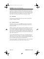
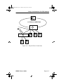
1
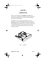
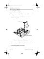
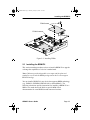
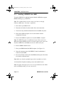
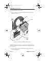
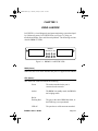
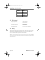
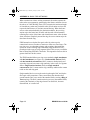
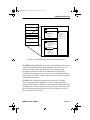
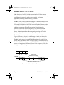
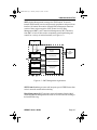
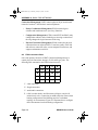
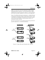
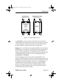
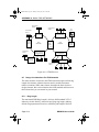
BRIM-F Book Page 1 Monday, January 29, 1996 9:26 AM
BRIM-F6
USER’S GUIDE
BRIM-F Book Page vii Monday, January 29, 1996 9:26 AM
CONTENTS
CHAPTER 1
1.1
1.2
1.3
1.4
1.5
Using This Manual ....................................................................... 1-2
Getting Help................................................................................. 1-2
BRIM-F6 Overview ...................................................................... 1-3
BRIM-F6 Features ....................................................................... 1-3
Related Documentation ............................................................... 1-4
CHAPTER 2
2.1
2.2
2.3
INTRODUCTION ......................................................... 1-1
INSTALLATION........................................................... 2-1
Unpacking the BRIM and the FPIM ............................................. 2-1
Installing FPIMs ........................................................................... 2-2
Installing the BRIM-F6 ................................................................. 2-3
2.3.1 Installing a BRIM-F6 into a MIM ..................................... 2-4
2.3.2 Installing a BRIM-F6 into a Hub...................................... 2-7
CHAPTER 3
USING LANVIEW ....................................................... 3-1
CHAPTER 4
SPECIFICATIONS....................................................... 4-1
4.1
4.2
4.3
4.4
4.5
Fiber Optic interface .................................................................... 4-1
Cable Specifications .................................................................... 4-5
Twisted Pair Pinout Configuration................................................ 4-7
Environment ................................................................................ 4-8
Safety .......................................................................................... 4-8
APPENDIX A
A.1
A.2
A.3
A.4
A.5
A.6
A.7
BASIC FDDI NETWORKS .........................................A-1
Basic FDDI Concepts ..................................................................A-1
FDDI Media Access Protocol.......................................................A-1
Reliability .....................................................................................A-3
ANSI Standard X3T9.5 ................................................................A-4
FDDI Connection Rules...............................................................A-8
FDDI Devices ..............................................................................A-9
Design Considerations for FDDI Networks ................................A-14
A.7.1 Ring Length ..................................................................A-14
A.7.2 Drive Distance ..............................................................A-15
A.7.3 Attenuation ...................................................................A-15
A.7.4 Bandwidth.....................................................................A-16
A.7.5 Number of Stations.......................................................A-16
BRIM-F6 User’s Guide
i
BRIM-F Book Page 1 Monday, January 29, 1996 9:26 AM
CHAPTER 1
INTRODUCTION
Welcome to the Cabletron Systems BRIM-F6 User’s Guide. This
manual describes features, explains installation procedures, and provides
specifications for the BRIM-F6 — Cabletron Systems FDDI Bridge/
Router Interface Module (BRIM).
The BRIM-F6 resides in, and provides additional connectivity/
functionality to, various Cabletron MIMs and hubs (e.g., the EMM-E6,
ESXMIM, NBR-420/620 or MicroMMAC). The BRIM-F6 utilizes two
FPIM (FDDI Port Interface Module) slots to provide you with the option
of using multimode fiber optic, single mode fiber optic, unshielded
twisted pair, or shielded twisted pair transceiver ports based on your
network requirements.
-F6
IM 6 S
BR IM-FV ST S
BR RC ST
IM
FP
R
FO FPIM
R
ED
RV D FO
SE
E
RE ERV
S
B
RE
IM
FP
B
IM
FP
T
V
XM RC
R
T
PW XM
R
K
PW
LN
R NK
W
L
T
P
R
WR TW
P
K
LN WR
K
LN
IM
FP
R
FO FPIM
R
ED
RV D FO
SE
E
RE ERV
S
A
RE
IM
FP
A
IM
FP
Figure 1-1. BRIM-F6
BRIM-F6 User’s Guide
Page 1-1
BRIM-F Book Page 2 Monday, January 29, 1996 9:26 AM
CHAPTER 1: INTRODUCTION
1.1
Using This Manual
Read through this manual completely to familiarize yourself with its
content and to gain an understanding of the features and capabilities of
the BRIM-F6.
In addition to having a general working knowledge of Ethernet and IEEE
802.3 type data communications networks and their physical layer
components, you should also understand FDDI networks and the ANSI
X3T9.5 standard prior to installing the BRIM-F6. For a review of FDDI,
see Appendix A, Basic FDDI Networks.
Chapter 1, Introduction, outlines the contents of this manual, highlights
BRIM-F6 features, and concludes with a list of related documentation.
Chapter 2, Installation, describes how to install FPIMs into the BRIM-F6
and how to install the BRIM-F6 into a Media Interface Module (MIM) or
a stand-alone hub.
Chapter 3, Using LANVIEW, describes how to use the front panel LEDs
to monitor BRIM performance.
Chapter 4, Specifications, lists various electrical and physical
specifications of the BRIM-F6.
Appendix A, Basic FDDI Networks, covers basic concepts of FDDI
networks, FDDI devices, and design/installation considerations.
1.2
Getting Help
If you need additional support related to the BRIM-F6, or if you have any
questions, comments, or suggestions concerning this manual, contact
Cabletron Systems Technical Support:
By phone ..........................(603) 332-9400
Monday-Friday; 8am - 8pm EST
By CompuServe®
GO CTRON from any ! prompt
By Internet mail [email protected]
Page 1-2
BRIM-F6 User’s Guide
BRIM-F Book Page 3 Monday, January 29, 1996 9:26 AM
BRIM-F6 Overview
1.3
BRIM-F6 Overview
The BRIM-F6 is an FDDI Bridge Router Interface Module (BRIM)
developed for use in Cabletron’s MMAC-FNB and MicroMMAC. The
BRIM-F6 can be used to provide a high-speed uplink from lower speed
networks such as Ethernet to a 100 Mbps FDDI backbone.
1.4
BRIM-F6 Features
Connectivity
The BRIM-F6 is equipped with slots for FDDI A and B ports. These two
ports allow connection to the ring as a Dual Attached Station (DAS) using
two FPIMs or as a Single Attached Station (SAS) using one FPIM.
As a DAS, the MIM or hub that houses the BRIM-F6 connects directly to
the FDDI main ring. This provides the reliability of an FDDI dual,
counter-rotating ring topology. If one segment of the FDDI ring becomes
disabled, this dual ring configuration provides redundancy and restores
ring continuity.
As a SAS, the BRIM-F6 connects to the primary ring only by using a
single FPIM on the BRIM-F6 to attach to the M port of an FDDI
concentrator.
A dual homing configuration provides an additional redundancy feature
for the MIM or hub containing the BRIM-F6. Dual homing is a way of
connecting to an FDDI ring through the Master (M type) ports of two
separate dual attached concentrators. If one M type port or one segment
fails, the redundant port or segment activates automatically to retain
connection to the ring.
For more information regarding DAS, SAS or dual homing
configurations, refer to Appendix A, Basic FDDI Networks.
Bridging
The BRIM-F6 provides translational bridging between any channels or
ports in its host MIM or hub and the FDDI ring.
BRIM-F6 User’s Guide
Page 1-3
BRIM-F Book Page 4 Monday, January 29, 1996 9:26 AM
CHAPTER 1: INTRODUCTION
LANVIEW Diagnostic LEDs
The BRIM-F6’s front panel LEDs help you diagnose Bridge, Port, and
Network status.
1.5
Related Documentation
Use the following documentation to supplement the procedures, and other
technical data in this manual. This manual may reference procedures in
these documents, where appropriate, but does not repeat them.
Cabletron Systems’ EMM-E6 Installation Guide
Cabletron Systems’ EMM-E6 Local Management Guide
Cabletron Systems’ ESXMIM Installation Guide
Cabletron Systems’ ESXMIM Local Management Guide
Cabletron Systems’ MicroMMAC User’s Guide
Cabletron Systems’ NBR-620/420/220 Installation Guide
Cabletron Systems’ NBR-620/420/220 Local Management Guide
Cabletron Systems’ Router Services Manuals
The Simple Book, An Introduction to Management of TCP/IP-based
Internets, Marshall T. Rose, Prentice-Hall, Inc., 1991.
Page 1-4
BRIM-F6 User’s Guide
BRIM-F Book Page 1 Monday, January 29, 1996 9:26 AM
CHAPTER 2
INSTALLATION
This chapter contains instructions for unpacking the BRIM-F6, installing
FPIMs, and installing the BRIM-F6 into Cabletron devices that support
BRIM technology.
Note: The BRIM-F6 is not shipped with the FPIMs installed. You must
order the correct FDDI Port Interface Modules based upon your network
requirements.
To install the BRIM and FPIMs, you need the following tools:
•
•
1 disposable wrist strap (provided with any BRIM, MIM or hub)
1 Phillips screwdriver.
Caution: Observe all static precautions while handling modules.
2.1
Unpacking the BRIM and the FPIMs
Unpack the modules as follows:
1. Remove the shipping box material covering the module.
2. Carefully remove the module from the shipping box. Leave the module
in its static-shielding bag until you are ready to install.
3. After removing the module from its static-shielding bag, visually
inspect the device. If you notice any signs of damage, contact
Cabletron Systems Technical Support immediately.
BRIM-F6 User’s Guide
Page 2-1
BRIM-F Book Page 2 Monday, January 29, 1996 9:26 AM
CHAPTER 2: INSTALLATION
2.2
Installing the FPIMs
To install an FPIM into the BRIM-F6:
1. Remove the screws securing the FPIM coverplate and the coverplate.
See Figure 2-1.
2. Insert the connector pins of the FPIM into the connector on the
BRIM-F6. See Figure 2-2.
FPIM Screws
IM
R
D
E
RV
FO
FP
SE
RE
IM
R
D
E
RV
-F6
IM 6 S
BR IM-FV ST S
BRT RC V ST
IM
FP
R
FO FPIM
R
ED
RV D FO
SE
E
RE ERV
S
B
RE
IM
FP
B
IM
FP
XM RC
R
T
PW XM
R
K
PW
LN
R
K
TW LN
P
R
WR TW
P
K
R
N
L
W
K
N
L
FO
FP
SE
RE
A
IM
FP
A
IM
FP
FPIM Coverplate
Figure 2-1. Removing the FPIM Coverplate
3. Press down firmly on the FPIM until the pins slide all the way into the
connector holes.
4. Secure the FPIM with the screws provided.
Page 2-2
BRIM-F6 User’s Guide
BRIM-F Book Page 3 Monday, January 29, 1996 9:26 AM
Installing the BRIM-F6
FPIM Screws
FPIM Connector
Standoffs
-F6
IM 6 S
BR IM-FV ST S
BRT RC V ST
IM
D
E
RV
OR
F
SE
RE
FP
XM
RC
R
T
PW
XM
R
K
PW
LN
R
K
LN
TW
P
R
R
W
TW
P
K
LN
WR
K
LN
IM
FP
R
IM
FO
FP
R
ED
RV D FO
SE
E
RE ERV
S
E
A
R
IM
FP
A
IM
FP
B
IM
FP
B
IM
FP
Figure 2-2. Installing FPIMs
2.3
Installing the BRIM-F6
This section contains procedures on how to install a BRIM-F6 to upgrade
or change the capabilities of a device’s motherboard.
Note: Cabletron provides disposable wrist straps and faceplate and
standoff screws in both the BRIM package and on devices that support
BRIM technology.
You can install a BRIM-F6 in any device that supports BRIM technology
(e.g., EMM-E6, ESXMIM, NBR-420/620, or MicroMMAC). The
following subsections provide instructions for installing a BRIM-F6 in a
MIM or in a stand-alone hub. Refer to specific MIM or hub
documentation for exact BRIM slot and connector locations.
BRIM-F6 User’s Guide
Page 2-3
BRIM-F Book Page 4 Monday, January 29, 1996 9:26 AM
CHAPTER 2: INSTALLATION
2.3.1
Installing a BRIM-F6 into a MIM
To install a BRIM-F6 in a Media Interface Module (MIM) that supports
BRIM technology (e.g., EMM-E6):
Note: We recommend that you power down your hub even though
Cabletron MIMs have “hot swap” capabilities.
1. Power-down your MMAC hub.
2. Disconnect all cables from the module. Note each connection.
3. Unscrew the top and bottom knurled knobs of the MIM face plate.
4. Slide out the MIM, and place it on its side with the internal
components facing up.
5. Remove the BRIM coverplate screws and the BRIM coverplate.
Note: The BRIM-F6 requires an additional 24 pin ribbon connection.
MIMs that support BRIMs provide one slot that supports this connection.
Install the BRIM-F6 in the BRIM slot with the ribbon cable jack.
6. Remove BRIM standoff screws.
7. Place your BRIM behind the MIM faceplate. (See Figure 2-3.)
8. Insert the connector pins of the BRIM-F6 into the motherboard
connector on the MIM.
9. Press down firmly on the back of the BRIM until the pins slide all the
way into the connector holes.
Note: Make sure that the standoffs align with the standoff screw holes.
10. Reinstall the faceplate mounting screws and standoff screws.
Note: Faceplate and support post screws are provided both on the MIM
and in the BRIM package, for your convenience.
Page 2-4
BRIM-F6 User’s Guide
BRIM-F Book Page 5 Monday, January 29, 1996 9:26 AM
Installing the BRIM-F6
Standoff
Screw
BR
V
T
WR
Standoff
-F6
IM
Connector
Pins
Under
BRIM
S
ST
RC
IM
A
FP
XM
P
K
R
P
K
WR
LN
TW
LN
IM
B
FP
Coverplate/
Faceplate
Screws
Motherboard
Connector
Figure 2-3. Installing the BRIM-F6
The BRIM-F6 requires a special 24 pin ribbon connector in addition to
the standard 96 pin BRIM connector. This ribbon connector allows the
BRIM-F6 to use in-line filtering functionality.
BRIM-F6 User’s Guide
Page 2-5
BRIM-F Book Page 6 Monday, January 29, 1996 9:26 AM
CHAPTER 2: INSTALLATION
To install the BRIM-F6 ribbon cable:
1. Insert one ribbon cable connector into the ribbon cable jack on the
BRIM. (See Figure 2-4.)
Tab
Ribbon
Cable
Connector
Groove
S
ST
P
R
WR
TW
V
T
RC
XM
Ribbon
Cable
Jack
Figure 2-4. Installing the BRIM-F6 Ribbon Cable
Caution: The ribbon cable connector only fits into the ribbon cable jack
one way. Fit the tab on the connector into the groove in the jack for correct
cable orientation.
2. Press down on the connector until the clips on the jack snap into a
vertical locked position.
Page 2-6
BRIM-F6 User’s Guide
BRIM-F Book Page 7 Monday, January 29, 1996 9:26 AM
Installing the BRIM-F6
3. Insert the remaining ribbon cable connector into the ribbon cable jack
on the MIM.
4. Press down on the connector until the clips on the jack snap into a
vertical locked position.
After returning the MIM to the chassis, returning power to your hub, and
reconnecting to the network, the BRIM-F6 is now ready for operation.
2.3.2
Installing a BRIM-F6 into a Hub
To install a BRIM-F6 into a stand-alone hub that supports BRIM
technology (e.g., MicroMMAC):
1. Power-down your hub.
2. Disconnect all cables from the hub. Note the port-to-cable
connections.
3. Remove the chassis cover.
Note: Refer to specific hub documentation for instructions on removing the
hub chassis cover.
4. Remove the BRIM coverplate/faceplate screws.
Note: The BRIM-F6 requires an additional 24 pin ribbon connection.
Hubs that support BRIM technology only provide one BRIM slot that
supports this connection. Make sure you install the BRIM-F6 in the BRIM
slot with the ribbon cable jack.
5. Remove BRIM standoff screws.
6. Remove the BRIM coverplate.
7. Place your BRIM behind the hub faceplate. (See Figure 2-3.)
8. Insert the connector pins of the BRIM-F6 into the motherboard
connector in the hub.
BRIM-F6 User’s Guide
Page 2-7
BRIM-F Book Page 8 Monday, January 29, 1996 9:26 AM
CHAPTER 2: INSTALLATION
9. Press down firmly on the back of the BRIM until the pins slide all the
way into the connector holes.
Note: Make sure that the standoffs align with the standoff screw holes.
10. Reinstall the coverplate/faceplate screws and standoff screws.
Note: Faceplate and support post screws are provided both on the hub and
in the BRIM package.
The BRIM-F6 requires a special 24 pin ribbon connector in addition to
the standard 96 pin BRIM connector. This ribbon connector allows the
BRIM-F6 to use in-line filtering functionality.
To install the BRIM-F6 ribbon cable:
1. Insert one ribbon cable connector into the ribbon cable jack on the
BRIM. (See Figure 2-4.)
Caution: The ribbon cable connector only fits into the ribbon cable jack
one way. Fit the tab on the connector into the groove in the jack for correct
cable orientation.
2. Press down on the connector until the clips on the jack snap into a
vertical locked position.
3. Insert the remaining ribbon cable connector into the ribbon cable jack
in the hub.
4. Press down on the connector until the clips on the jack snap into a
vertical locked position.
After returning the cover, returning power to your device, and
reconnecting to the network, your BRIM-F6 is now ready for operation.
Page 2-8
BRIM-F6 User’s Guide
BRIM-F Book Page 1 Monday, January 29, 1996 9:26 AM
CHAPTER 3
USING LANVIEW
LANVIEW is a visual diagnostic and status monitoring system developed
by Cabletron Systems. LANVIEW LEDs (see Figure 3-1) help you
troubleshoot Bridge, Port, and Network problems. The following sections
describe BRIM-F6 LEDs.
BRIM-F6
PWR XMT RCV STS
FPIM B
FPIM A
LNK WRP TWR LNK
Figure 3-1. BRIM-F6 LANVIEW LEDs
PWR (Power)
When ON, this Green LED indicates that power is supplied to the BRIM.
STS (Status)
This multi-state LED can indicate the following:
Green
The station attached to the port is
connected to the network.
Amber
The BRIM is in standby mode; the BRIM is
not bridging traffic.
Red or
Flashing Red
LED off
BRIM-F6 User’s Guide
The port or the entire BRIM has failed, or
the FDDI ring is not operational.
The port has no valid connector attached.
Page 3-1
BRIM-F Book Page 2 Monday, January 29, 1996 9:26 AM
CHAPTER 3: USING LANVIEW
TWR (Twisted Ring)
When ON, this Red LED indicates an undesirable cable connection. TWR
illuminates when you connect A to A, or B to B, instead of A to B, or B to
A. The BRIM-F6 supports undesirable configurations, but alerts you to
them. (Appendix A summarizes FDDI connection rules.)
WRP (Wrap)
This Red LED is ON when the BRIM-F6 detects an FDDI ring wrap. This
means there is a break in the ring, and the system has combined the
primary and secondary rings into one ring.
XMT (Transmit)
When ON, this Green LED indicates that the BRIM-F6 is transmitting
traffic to the FDDI network. On a network with average traffic, the XMT
LED normally flashes.
RCV (Receive)
When ON, this Amber LED indicates that the BRIM-F6 is receiving
FDDI traffic. On a network with average traffic, the RCV LED normally
flashes.
LNK (Media Link OK)
When ON, this Green LED indicates that a connection exists between the
BRIM-F6 and the node at the other end of the port cable segment. To
ensure you maintain the link, the port generates an idle signal when not
transmitting data.
When OFF, this LED indicates that either nothing is connected to the
BRIM-F6, or the port is not receiving any signal.
Page 3-2
BRIM-F6 User’s Guide
BRIM-F Book Page 1 Monday, January 29, 1996 9:26 AM
CHAPTER 4
SPECIFICATIONS
This chapter lists the operating specifications for the BRIM-F6. Cabletron
Systems reserves the right to change these specifications at any time,
without notice.
4.1
Fiber Optic Interface
Depending on the FPIM, interfaces have the following characteristics:
Multimode Specifications
Multimode Transmitter
Optical wavelength:
1330 nm typical
Optical output:
-20.0 dBm minimum
-14.0 dBm maximum
Optical rise time:
3.5 nsec maximum
Optical fall time:
3.5 nsec maximum
Spectral width:
140 nm typical
Supply current:
150 mAmps maximum
Multimode Receiver
Optical wavelength:
1330 nm typical
Optical input:
(avg. sensitivity)
-31.0 dBm minimum
-14.0 dBm maximum
Output rise time:
3 nsec maximum
Output fall time:
3 nsec maximum
Supply current:
150 mAmps maximum
BRIM-F6 User’s Guide
Page 4-1
BRIM-F Book Page 2 Monday, January 29, 1996 9:26 AM
CHAPTER 4: SPECIFICATIONS
Multimode Receiver (Signal Detect)
Assert power:
-33.0 dBm typical
-31.0 dBm maximum
Assert time:
10 µsec typical
100 µsec maximum
Deassert power:
-36.0 dBm typical
-45.0 dBm minimum
Deassert time:
10 µsec typical
350 µsec maximum
Hysteresis:
1.5 dB minimum
Single Mode Specifications
Single Mode Transmitter
Page 4-2
Optical wavelength:
1330 nm typical
Optical output:
-20.0 dBm minimum
-14.0 dBm maximum
Optical rise time:
3.5 nsec maximum
Optical fall time:
3.5 nsec maximum
Spectral width:
150 nm maximum
Supply current:
150 mAmps maximum
BRIM-F6 User’s Guide
BRIM-F Book Page 3 Monday, January 29, 1996 9:26 AM
Single Mode Specifications
Single Mode Receiver
Optical wavelength:
1330 nm typical
Optical input:
(avg. sensitivity)
-31.0 dBm minimum
-14.0 dBm maximum
Output rise time:
3 nsec maximum
Output fall time:
3 nsec maximum
Supply current:
115 mAmps maximum
Single Mode Receiver (Signal Detect)
Assert power:
-33.0 dBm typical
-31.0 dBm maximum
Assert time:
10 µsec typical
100 µsec maximum
Deassert power:
-36.0 dBm typical
-45.0 dBm minimum
Deassert time:
10 µsec typical
350 µsec maximum
Hysteresis:
1.5 dB minimum
BRIM-F6 User’s Guide
Page 4-3
BRIM-F Book Page 4 Monday, January 29, 1996 9:26 AM
CHAPTER 4: SPECIFICATIONS
Unshielded Twisted Pair Specifications
Unshielded Twisted Pair Transmitter
Amplitude
1.080 Vpk maximum
0.920 Vpk minimum
Rise time
2 nsec minimum
4 nsec maximum
Fall time
2 nsec minimum
4 nsec maximum
Rise/Fall variation
0.5 nsec maximum
Overshoot
5% maximum
Droop (14 symbols)
3% maximum
Unshielded Twisted Pair Receiver
(Signal Detect)
Assert time
Page 4-4
10 µsec typical
100 µsec maximum
BRIM-F6 User’s Guide
BRIM-F Book Page 5 Monday, January 29, 1996 9:26 AM
Shielded Twisted Pair Transmitter Specifications
Unshielded Twisted Pair Receiver
(Signal Detect)
Deassert time
10 µsec typical
350 µsec maximum
Shielded Twisted Pair Transmitter Specifications
Shielded Twisted Pair Transmitter
Amplitude
1.285 Vpk maximum
1.165 Vpk minimum
Rise time
3 nsec minimum
5 nsec maximum
Fall time
3 nsec minimum
5 nsec maximum
Rise/Fall variation
0.5 nsec maximum
Overshoot
5% maximum
Shielded Twisted Pair Receiver
(Signal Detect)
4.2
Assert time
10 µsec typical
100 µsec maximum
Deassert time
10 µsec typical
350 µsec maximum
Cable Specifications
The FDDI Physical Layer Medium Dependent (PMD), Twisted Pair
Physical Layer Medium Dependent (TP-PMD), and Single Mode Fiber
Physical Layer Medium Dependent (SMF-PMD) ANSI standards define
cable requirements as follows:
BRIM-F6 User’s Guide
Page 4-5
BRIM-F Book Page 6 Monday, January 29, 1996 9:26 AM
CHAPTER 4: SPECIFICATIONS
Multimode Fiber:
Core diameter:
62.5 µm nominal
Cladding diameter:
128.0 µm maximum
122.0 µm minimum
Cable attenuation:
≤ 2.5 dB/km typical
Single Mode Fiber:
Core diameter:
8.7 µm +/- 0.5 µm
Cladding diameter:
127.0 µm maximum
Cable attenuation:
≤ 0.5 dB/km typical
Multimode Fiber Optic Cable Length
The PMD FDDI standard specifies the following:
Maximum total
cable length:
Maximum multimode
cable length between
adjacent nodes:
100 km (62 miles) — dual ring
200 km (124 miles) — wrapped
2 km (1.2 miles)
Single Mode Fiber Optic Cable Length
The SMF-PMD FDDI standard specifies the following:
Maximum total
cable length:
Single mode cable length
between adjacent nodes:
100 km (62 miles) — dual ring
200 km (124 miles) — wrapped
40 km (24 miles) maximum
25 km (15 miles) typical
Twisted Pair Cable Length
The TP-PMD FDDI standard specifies the following:
Page 4-6
BRIM-F6 User’s Guide
BRIM-F Book Page 7 Monday, January 29, 1996 9:26 AM
Twisted Pair Cable Length
Maximum total
cable length:
100 km (62 miles) — dual ring
200 km (124 miles) — wrapped
Maximum twisted
pair cable length between
adjacent nodes:
4.3
100 m (328.1 feet)
Twisted Pair Pinout Configuration
This section provides the RJ-45 pinout configuration for Unshielded
Twisted Pair (UTP) and Shielded Twisted Pair (STP) Physical Layer
Medium Dependent (PMD) ports.
Note: When connecting two twisted pair ports together, a transmit and receive
cross-over must occur between the two devices (within the cable).
Pin 1
Pin 8
Figure 4-1. RJ-45 TP-PMD Port
Contact
Signal
1
Transmit +
2
Transmit -
3
N/A
4
N/A
5
N/A
BRIM-F6 User’s Guide
Page 4-7
BRIM-F Book Page 8 Monday, January 29, 1996 9:26 AM
CHAPTER 4: SPECIFICATIONS
Contact
4.4
4.5
Signal
6
N/A
7
Receive +
8
Receive -
Environment
Storage temperature:
-40°C minimum
85°C maximum
Operating temperature:
5°C minimum
40°C maximum
Operating humidity:
5% to 95% non-condensing
Safety
This unit meets the safety requirements of UL 1950, CSA C22.2 No. 950,
and EN 60950; the EMI requirements of FCC Class A and EN 55022
Class A; and the EMC requirements of EN 50082-1.
Note: It is the responsibility of the person who sells the system to which the BRIM
will be a part to ensure that the total system meets allowed limits of conducted and
radiated emissions.
Page 4-8
BRIM-F6 User’s Guide
BRIM-F Book Page 1 Monday, January 29, 1996 9:26 AM
APPENDIX A
BASIC FDDI NETWORKS
This Appendix covers basic Fiber Distributed Data Interface (FDDI)
network concepts relating to FDDI network design and installation.
ANSI Standard X3T9.5 provides greater detail on FDDI access methods.
Reference this standard whenever you need more complete information.
Specific areas presented here include:
•
Basic FDDI Concepts
•
FDDI Devices
•
Design and Installation Considerations.
A.1
Basic FDDI Concepts
An FDDI network provides a high-speed (100 Mbit/sec.), fiber optic
network capable of reliable data transmission. The fiber optic media
provides increased bandwidth, immunity from electrical noise, security,
and permits the use of longer cable segments. These features make FDDI
a viable alternative in LAN backbone applications, or as a back-end or
front-end network between processors.
A.2
FDDI Media Access Protocol
The FDDI standard X3T9.5 describes the media access and token passing
protocol for FDDI networks. Each station on an FDDI ring has a unique
station address, differentiating it from all other stations. A special frame,
called a token, controls transmission.
Only one station, the station holding the token, can transmit at any given
time. This token circulates around the ring from station to station. Each
station receives the token from the station preceding it on the ring, retains
it while transmitting data (frames) and then passes (transmits) the token
on to the next active station on the ring.
BRIM-F6 User’s Guide
Page A-1
BRIM-F Book Page 2 Monday, January 29, 1996 9:26 AM
APPENDIX A: BASIC FDDI NETWORKS
When a station has a frame waiting to transmit, the station captures the
token at the next opportunity, transmits the data frame, and then reissues
the token. (A Token Holding Timer (THT) controls the maximum length
of time that any station may retain the token.) Each station receives and
repeats the data frame as it circulates around the ring. When the frame
arrives at the station defined by the destination address, the receiving
station copies the frame into its buffer and forwards with information
reflecting the receipt of the frame and related frame status. After the data
frame circulates completely around the ring, the source station strips the
data frame from the ring.
FDDI networks use duplex fiber optic cable for point-to-point
connections between a number of stations to form two closed loops. The
two rings serve as redundant (primary and secondary) data paths that
operate as counter-rotating rings. Redundant rings facilitate recovery
procedures in the event of a ring segment failure. This recovery resembles
that in Token Ring/IEEE 802.5 networks. This Appendix discusses this in
greater detail later in this section.
The FDDI standard defines two ring access methods, single attachment
and dual attachment (see Figure A-1). Dual attached stations (DAS)
and dual attached concentrators (DAC) connect to both primary and
secondary rings and can restore ring continuity in the event of a segment
failure. Single attached stations (SAS) and single attached
concentrators (SAC) cannot restore ring continuity and therefore cannot
reside on the main ring path.
Single attached devices access the main ring through a DAC and duplex
fiber optic cable connections. These connections form branches that
extend from the DAC out to each of the attached SASs, creating a Ring of
Trees topology. The DAC controls main ring access to the attached SASs,
restoring the continuity of the ring whenever an SAS fails, becomes
disconnected, or is turned-off.
Page A-2
BRIM-F6 User’s Guide
BRIM-F Book Page 3 Monday, January 29, 1996 9:26 AM
Reliability
Ethernet/802.3
Network
Ethernet/802.3
Network
ETHERNET to
FDDI BRIDGE
ETHERNET
to FDDI
BRIDGE
FDDI
NETWORK
DUAL
ATTACHED
STATION
File
Server
DUAL ATTACHED
CONCENTRATOR
SINGLE ATTACHED
CONCENTRATOR
Single Attached
Stations
Figure A-1. Typical FDDI Physical Installation
A.3
Reliability
FDDI networks employ a ring topology and are inherently vulnerable to
the frailties of each ring segment and failures of individual stations. The
ring of trees topology reduces the risk of a single node bringing the entire
network down.
A redundant data path, within the main ring trunk cabling, further reduces
this vulnerability. In theory, to achieve the circular data flow, the ring
topology requires media that allows only one-way traffic. In practice, an
FDDI ring uses media that provides two fiber optic ring paths, a primary
ring and a secondary ring. The secondary ring restores the continuity of
the ring in the event a node fails node or a trunk segments (a trunk cable
breaks). Figure A-2 illustrates how the open ends of the primary ring
wrap into the secondary ring, restoring continuity by creating a new ring.
BRIM-F6 User’s Guide
Page A-3
BRIM-F Book Page 4 Monday, January 29, 1996 9:26 AM
APPENDIX A: BASIC FDDI NETWORKS
CONCENTRATOR 3
PRIMARY
RING
B
WRAP
A
B
SECONDARY
RING
A
CONCENTRATOR 4
CONCENTRATOR 2
B
A
B
A
CONCENTRATOR 1
Figure A-2. Wrapping a Broken Ring
A.4
ANSI Standard X3T9.5
The X3T9.5 standard includes: Station Management (SMT), Media
Access Control (MAC), Physical Layer Medium Dependent (PMD)
standards and Physical Layer Protocol (PHY). Each section defines a
unique entity of the FDDI station architecture and its operation.
The X3T9.5 entities perform many of the lower layer functions of the OSI
network model Data Link and Physical Layers (Figure A-3).
Page A-4
BRIM-F6 User’s Guide
BRIM-F Book Page 5 Monday, January 29, 1996 9:26 AM
ANSI Standard X3T9.5
Application
Data Link
Presentation
LLC
Session
Transport
Network
MAC
Media Access Control
• Medium Addressing
• Data Checking
• Data Framing
SMT
Station Management
• Fault Isolation and
Recovery
• Station Configuration
• Scheduling Procedures
Data Link
Physical
Physical
PHY
Physical Layer Protocol
• Symbol Coding/Decoding
• Symbol Framing
• Clock Rate
PMD or SMF-PMD
Physical Layer Medium Dependent
• Power Levels
• Transmitter
• Receiver
• Optical Interface
• Connector Types
Figure A-3. FDDI Structure and the OSI Network Model
The PMD standard establishes the physical characteristics of the network
connection, including the fiber optic transmitter power levels, receiver
sensitivity, the fiber optic cable type, the type of connectors, and
acceptable losses between nodes. The PMD converts the optically
encoded information that it receives to electrically encoded information
and presents it to the PHY sublayer. The layers reverse this process when
transmitting information.
The PHY entity implements the physical layer protocol. The PHY
receives data frames from the MAC as a series of 4-bit symbols and
encodes each 4-bit MAC symbol as a 5-bit symbol for transmission. This
encoding occurs to ensure each symbol has at least two bit transitions for
bit-cell synchronization at the remote receiver. Decoding reverses this
process for the received frames.
BRIM-F6 User’s Guide
Page A-5
BRIM-F Book Page 6 Monday, January 29, 1996 9:26 AM
APPENDIX A: BASIC FDDI NETWORKS
Other functions of the PHY include generation of a 125 Mhz transmit
clock, synchronization of the receive clock with an upstream transmitter,
encoding and decoding for media control symbols, and in some
applications, buffering for the incoming bit stream.
The MAC entity resides on the lower sublayer of the Data Link layer. The
upper sublayer, Logical Link Control (LLC) serves as an interface
between the OSI model and the FDDI network. The MAC element, under
control of Station Management, performs many of the tasks associated
with frame preparation and media access: ring scheduling, token
generation, timers that monitor ring activity, ring initialization, and
beaconing. Other tasks for the MAC entity include assembling data
frames, maintaining medium addressing, and generating and checking
data check bytes.
The MAC generates two basic message formats, tokens and frames.
Figure A-4 shows the layout for each message. Control and format bits
within the header define specific types of frames and classes of tokens.
The MAC sublayer receives transmittable Data frames from the LLC as
Service Data Units (SDUs). MAC uses these SDUs to construct Protocol
Data Units (PDUs) that it passes on to PHY. The PDUs consist of a MAC
header, the encapsulated SDU, and a Frame Check Sequence (FCS). The
MAC generates FCS during transmission.
TOKEN
Starting
Frame
Ending
Preamble
Delimiter
Control
Delimiter
≥ 16 Symbols 2 Symbols 2 Symbols 2 Symbols
JK
FRAME
TT
Frame Check
Sequence Coverage
T
Starting
Frame
Frame Check
Ending
Preamble
Address Source Address
Information
Control Destination
Delimiter Frame Status
≥ 16 Symbols 2Delimiter
4 or 12 Symbols
4 or 12 Symbols ≥ 0 Symbol Pairs 8Sequence
Symbols 2 Symbols
Symbols 1 Symbols ≥ 3 Symbols
Maximum - 9000 Symbols
Figure A-4. Token and Frame Formats
Page A-6
BRIM-F6 User’s Guide
BRIM-F Book Page 7 Monday, January 29, 1996 9:26 AM
ANSI Standard X3T9.5
SMT (Station Management) manages the FDDI station. It controls
internal FDDI station processes and protocol compliance and provides an
interface for human intervention. Internal SMT management functions
consist of three major categories: SMT Frame Services, Ring
Management (RMT), and Connection Management (CMT). Interfaces
from SMT to each of these station components permit monitoring and
control for a variety of station functions (see Figure A-5).
LLC
FDDI STATION
SMT
SMT Frame
Services
MAC
LAN
Management
(Agent)
Ring Management
Configuration Path
Switch
Configuration Management
PHY
Physical Connection
Management
PMD
Bypass Switch
(optional)
In
Bypass Switch
Control
Out
Figure A-5. SMT Management Organization
SMT Frame Services generates and interprets special FDDI frames that
assist in network control and monitoring.
Ring Management (RMT) monitors status information from the MAC
and Configuration Management and controls several functions relating to
the health of the ring.
BRIM-F6 User’s Guide
Page A-7
BRIM-F Book Page 8 Monday, January 29, 1996 9:26 AM
APPENDIX A: BASIC FDDI NETWORKS
Connection Management (CMT) controls physical layer insertion and
removal of stations. CMT has three main components:
•
Entity Coordination Management (ECM) controls bypass
switches and coordinates trace (recovery) functions.
•
Configuration Management (CFM) controls PHY and MAC entity
configuration within a node. Attaching or removing a station from
the ring changes the logical structure of the ring.
•
Physical Connection Management (PCM) controls the physical
connection between adjacent PHYs. It tests the quality of the link
and enforces connection rules, screens marginal connections, and
supports maintenance activities.
A.5
FDDI Connection Rules
One of the primary functions of SMT Connection Management is to
control physical connections among A, B, M, and S type ports. The
following table summarizes the FDDI connection rules.
A
B
S
M
A
V,U
V
V,U
V,P
B
V
V,U
V,U
V,P
S
V,U
V,U
V
V
M
V
V
V
X
V - valid connection
X - illegal connection
U - undesirable connection
P - valid, but when both A and B connect to M ports, only the B
connection is active. Connecting A and B to M ports creates a dual
homing configuration. Dual homing provides a redundant
topology for concentrators. Figure A-6 illustrates how to configure
three concentrators into dual homing configuration.
Page A-8
BRIM-F6 User’s Guide
BRIM-F Book Page 9 Monday, January 29, 1996 9:26 AM
FDDI Devices
Port A
Port A
Port B
1
Port M
Port B
2
Port M
Backup
Connection
Port M
Port M
Primary
Port B Connection
Port A
3
Figure A-6. Dual Homing Topology
Concentrator 3 in Figure A-6 has redundant connections to the main ring
through either concentrator 1 or 2. The FDDI connection rules only
permit one active connection, Port B. If a cable failure severs concentrator
3’s connection to concentrator 2, CFM activates Port A.
A.6
FDDI Devices
FDDI recognizes four station configurations (SAS, DAS, DAC, and
SAC). These configurations differ by the mix of FDDI entities within the
station (see Figure A-7).
All stations must have:
•
•
•
•
one SMT
at least one MAC
one PMD
one PHY.
BRIM-F6 User’s Guide
Page A-9
BRIM-F Book Page 10 Monday, January 29, 1996 9:26 AM
APPENDIX A: BASIC FDDI NETWORKS
Each physical ring connection requires:
•
•
one PMD
one PHY.
A SAS consists of:
•
•
•
•
one SMT
one MAC
one PMD
one PHY.
A DAS consists of:
•
•
two PMDs
two PHYs.
Single Attached
Concentrator
Dual Attached
Concentrator
PMD-3
PMD-2
PMD-1
PHY-3
PHY-2
PHY-1
MAC
MAC
PMD-3
PMD-2
PMD-1
PHY-3
PHY-2
PHY-1
MAC
PHY
PMD
SMT
In
SMT
PHY-A
PHY-B
PMD-A
PMD-B
Secondary
Out
Primary
In
Out
MAC
MAC
Secondary
In
Primary
Out
MAC
PHY
PHY-A
PHY-B
PMD-A
PMD-B
PMD
SMT
SMT
Single Attached
Station
Dual Attached
Station
In
Out
Primary
In
Secondary
Out
Secondary
In
Primary
Out
Figure A-7. Valid Station Configurations
Page A-10
BRIM-F6 User’s Guide
BRIM-F Book Page 11 Monday, January 29, 1996 9:26 AM
FDDI Devices
FDDI devices physically attach to the ring using Fixed Shroud Duplex
(FSD) media interface connectors. The X3T9.5 Physical Layer, PMD
standard defines four connector types (see Figure A-7). These connectors
provide proper trunk fiber alignment for each of the valid configurations.
Types A, B, and M provide precision connection (i.e., mechanical keying
to assure proper connection to Primary-In and Primary-Out fibers). Types
A and B allows dual attachment to the primary and secondary data paths
of the main ring. Type M allows for single attachment stations, at a
concentrator end of the SAS lobe.
The Type S connector has a wide, centrally located, keyway provides nonprecision connection (i.e., for SAS lobe attachment).
FDDI RECEPTACLES
PRIMARY IN
FDDI CONNECTORS
SECONDARY OUT
Type A
TYPE A
Dual
DUAL
Attachment
ATTACHMENT
SECONDARY IN
PRIMARY OUT
Type B
TYPE B
IN
OUT
Type M
TYPE M
SINGLE
Single
ATTACHMENT
Attachment
IN
OUT
Type S
TYPE S
Figure A-8. Duplex Fiber Optic Receptacles and Connectors
BRIM-F6 User’s Guide
Page A-11
BRIM-F Book Page 12 Monday, January 29, 1996 9:26 AM
APPENDIX A: BASIC FDDI NETWORKS
Optical bypass switches, concentrators, and bridges exist throughout
FDDI networks. These devices allow creation of ring topologies that meet
the specific needs of different network applications.
Repeaters, often found in other network topologies, do not exist as entities
for FDDI networks. This is because all devices that attach to the FDDI
main ring must comply with FDDI protocol. In other words, they must
dual attach to the ring and have, as a minimum, two PMD and PHY
entities and one MAC and SMT entity.
Since a DAS or DAC can match this configuration, either could serve as a
repeater when a main ring segment must extend beyond the 2 km
maximum between nodes.
Together with Figure A-10, the following descriptions provide a brief
introduction to several FDDI components and their network functions. In
many cases, specific functions combine in a single device.
An optical bypass switch allows insertion between a station and the
FDDI ring connections without having to remove the station from the ring
and disturbing ring continuity. These devices, often electrically actuated,
provide passive optical switching of both the primary and secondary ring
cables. Figure A-9 shows the data paths through the switch in both the
bypass and operational (non-bypassed) states.
Page A-12
BRIM-F6 User’s Guide
BRIM-F Book Page 13 Monday, January 29, 1996 9:26 AM
FDDI Devices
BYPASS STATE
Station Power Off
OPERATIONAL STATE
Station Power On
STATION
STATION
FDDI Dual
Optical Bypass
Switch
FDDI Dual
Optical Bypass
Switch
FDDI
RING
FDDI
RING
Figure A-9. Optical Bypass Switch
A concentrator is a hub. It provides connections to the dual ring for
single attached stations and controls their access to the ring. The network
can optically bypass each main ring connection if the attached station
becomes disabled or when the branch cable is disconnected.
Bridging devices for FDDI connect multiple FDDI networks and link an
FDDI ring to a network that uses a different MAC layer protocol (Token
Ring or Ethernet). A bridge does not expand an existing FDDI ring, it
connects rings. Bridges that link two different MAC layer protocols, such
as FDDI and Ethernet, typically use one of two bridging techniques,
encapsulation or translation.
Translation bridges translate frames from a non-FDDI MAC layer
protocol to FDDI, allowing, for instance, an Ethernet station to talk to an
FDDI station. Encapsulation bridges enclose the non-FDDI frames within
the FDDI protocol. These bridges work in pairs – the sending bridge
encapsulates the message and the receiving bridge strips the FDDI
protocol, restoring the original frame. The bridge maintains routing
information for filtering (prevent frames from crossing the bridge) or
forwarding messages across the bridge.
BRIM-F6 User’s Guide
Page A-13
BRIM-F Book Page 14 Monday, January 29, 1996 9:26 AM
APPENDIX A: BASIC FDDI NETWORKS
Ethernet/802.3
Network
Single Attached
Stations
File
Server
Ethernet/802.3
Network
ETHERNET to
FDDI BRIDGE
ETHERNET
to FDDI
BRIDGE
FDDI
NETWORK
DUAL ATTACHED
CONCENTRATOR
FDDI
to
FDDI
BRIDGE
FDDI
NETWORK
DUAL
ATTACHED
STATION
DAS
Ethernet/802.3
Network
DUAL ATTACHED
CONCENTRATOR
DUAL ATTACHED
CONCENTRATOR
ETHERNET to
FDDI BRIDGE
SINGLE ATTACHED
CONCENTRATOR
Single Attached
Stations
Figure A-10. FDDI Devices
A.7
Design Considerations For FDDI Networks
The main variables of interest to the FDDI network designer include ring
length, drive distance (distance between nodes), and the maximum
number of stations. While many factors determine the limits for these
design elements, this section examines the ANSI standard and focuses on
those factors that you can control in your network.
A.7.1
Ring Length
The maximum FDDI Ring Length is 100 km. ANSI standard X3T9.5
indirectly sets this limit by, instead of specifying ring length, defining
default design parameters based on a total fiber path length of 200 km.
Page A-14
BRIM-F6 User’s Guide
BRIM-F Book Page 15 Monday, January 29, 1996 9:26 AM
Design Considerations For FDDI Networks
To translate fiber path to ring length, remember that FDDI networks
contain two counter-rotating rings. Under normal conditions (no failed
segment), the ring length remains the same as the fiber path length.
However, if a wrap occurs, the length of the fiber path length could nearly
double. To safely establish the maximum ring length, divide the fiber
length by two. This yields a maximum ring length 100 km (one-half of the
200 km fiber path length).
In designing your network, you must add all of the lengths of the fiber
optic cables in your network to determine the total ring length. This
includes main ring cables and branch cables that reach from concentrators
to SASs.
A.7.2
Drive Distance
Drive distance is the limit of reliable signal propagation around the ring.
(i.e., the greatest distance that a signal can travel on the ring and still be
reliably received). For FDDI networks using multimode fiber the
maximum drive distance is 2 km. For networks using single mode fiber,
the maximum drive distance is up to 40 km (25 km typical) depending on
transceiver type.
To the network designer, this means that the maximum cable length
between any two network nodes must not exceed the 2 km maximum
distance limit for multimode or 25 km typical distance for single mode.
In some multimode applications, existing 50/125 µm or 100/140 µm fiber
operates over longer distances. However, the cable must conform to the
FDDI standard for bandwidth and attenuation to remain compliant with
the FDDI standard. The 40 km maximum for single mode fiber is for
absolute best-case (i.e., not for practical application).
A.7.3
Attenuation
The maximum attenuation (attenuation budget) between any two active
connections to the ring, according to the FDDI standard, is 11 dB. This
budget includes the attenuation of the cabling, splices, connections, and
optical bypass switches.
BRIM-F6 User’s Guide
Page A-15
BRIM-F Book Page 16 Monday, January 29, 1996 9:26 AM
APPENDIX A: BASIC FDDI NETWORKS
The attenuation of the typical multimode fiber optic cable used in FDDI
networks is 2.5 dB/km or 5 dB for the 2 km maximum node separation.
When installing optical bypass switches, each switch could add 2.5 dB to
the attenuation. With an 11 dB budget to work with, and 5 dB expended
on the cable, you can install a maximum of two bypass switches.
A.7.4
Bandwidth
The minimum modal bandwidth of fiber optic cable used in an FDDI
network is 500 Mhz at 1300 nm.
A.7.5
Number of Stations
The number of devices in a single FDDI ring cannot exceed 500. The
amount of propagation delay generated by 1000 physical connections
determines this limit.
With the exception of optical bypass switches, all FDDI devices count as
two connections against the 1000 physical connection budget. You can
easily see how to calculate this number when only dual attached stations
reside on the network (1000 divided by 2 connections for each DAS = 500
nodes). However, to understand how to count connections for other device
types, refer to Figure A-11.
A DAC without attached devices counts as two connections (main ring
connections), the same as a DAS. As you attach each additional SAS or
SAC to the DAC, you must count two connections against the budget, one
for the concentrator port and one for the attached device.
This same logic applies to counting connections for a SAC. The multiple
ports of the concentrator do not count until you attach a device.
Page A-16
BRIM-F6 User’s Guide
BRIM-F Book Page 17 Monday, January 29, 1996 9:26 AM
Design Considerations For FDDI Networks
DAS
2
16 PHYSICAL CONNECTIONS
DAC
1
+1
2
2
SAC
2
2
SAS
2
SAS
2
SAS
2
SAS
2
SAS
Figure A-11. Physical Device Connections
BRIM-F6 User’s Guide
Page A-17