1
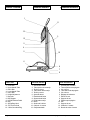
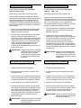
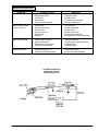
E
530 / 530cc
Operating
Instructions
Upright
Vacuum
Instrucciones
De Operacion
Barredoras
Verticales
Instructions
D'Operation
Balayeuse
READ THIS BOOK
This book has important information for the use and safe operation of this machine. Failure to read
this book prior to operating or attempting any service or maintenance procedure to your ALTO
machine could result in injury to you or to other personnel; damage to the machine or to other property
could occur as well. You must have training in the operation of this machine before using it. If
operator(s) cannot read English, have this manual explained fully before attempting to operate this
machine.
All directions given in this book are as seen from the operator’s position at the rear of the machine.
For new books write to: ALTO U.S. Inc., 2100 Highway 265, Springdale, Arkansas 72764.
Form No. 70069A
7/99
Clarke Technology
Printed in the U.S.A.
Table of Contents
Important Safety Instructions .................................................................................. 5
Grounding Instructions ............................................................................................ 8
General Diagram and Parts List ............................................................................. 10
How To Assemble ................................................................................................... 11
How To Use ............................................................................................................ 14
Height Adjustment ................................................................................................... 14
How To Change Disposable Paper Bag .................................................................. 16
How To Clean Permanent Bag ................................................................................ 16
How To Replace Brush Roll Belt ............................................................................. 18
How To Replace Motor ........................................................................................... 20
Page -2-
CLARKE TECHNOLOGY 530 Upright Vacuum Operator's Manual
Table of Contents
Advertencias ........................................................................................................... 6
Instrucciones Para La Conexion Electrica De Maquina ........................................... 8
Diagrama General/Lista de Partes ......................................................................... 10
Commo Ensambler ................................................................................................. 12
Commo Utilizarse .................................................................................................... 15
Ajuste De Altura ...................................................................................................... 15
Como Cambiar La Bolsa De Papel ......................................................................... 17
Como Limpiar Bolsa Permanente ........................................................................... 17
Como Reponer La Baner De Cepillo Girantorio ...................................................... 19
Como Reemplazar El Motor ................................................................................... 21
CLARKE TECHNOLOGY 530 Upright Vacuum Operator's Manual
Page -3-
Table of Contents
Importantes Mesures De Sécurité .......................................................................... 7
Instructions Visant La Mise A La Terre .................................................................... 9
Diagramme Generale/Liste Des Pieces .................................................................. 10
Comment L'Assembler ............................................................................................ 13
Comment L'Utiliser .................................................................................................. 15
Reglage De La Hauteur .......................................................................................... 15
Comment Changer Le Sac De Papier ..................................................................... 17
Comment Essuyer Le Sac Permanent .................................................................... 17
Comment Remplacer La Courroie De La Brosse .................................................... 19
Comment Remplacer Le Moteur ............................................................................. 21
Page -4-
CLARKE TECHNOLOGY 530 Upright Vacuum Operator's Manual
This machine is intended for commercial use.
IMPORTANT SAFETY INSTRUCTIONS
WHEN USING AN ELECTRICAL UPRIGHT VACUUM CLEANER, BASIC PRECAUTIONS SHOULD BE
FOLLOWED, INCLUDING THE FOLLOWING:
READ ALL INSTRUCTIONS BEFORE USING VACUUM CLEANER.
SAVE THESE INSTRUCTIONS FOR FUTURE REFERENCE.
WARNING:
To reduce the risk of fire, electric shock, or injury:
1. Do not use outdoors or on wet surfaces.
2. Do not leave vacuum cleaner unattended when plugged in. Turn off the switch and unplug the
electrical cord when not in use and before servicing.
3. Do not allow to be used as a toy. Close attention is necessary when used by or near
children.
4. Use only as described in this manual. Use only manufacturer's recommended attachments.
5. Do not use with damaged cord or plug. If vacuum cleaner is not working as it should, has
been dropped, damaged, left outdoors, or dropped into water, return it to a service center
before using.
6. Do not pull or carry by cord, use cord as a handle, close a door on cord, or pull a cord around
sharp edges or corners. Do not run vacuum cleaner over cord. Keep cord away from heated
surfaces.
7. Do not use extension cords or outlets with inadequate current carrying capacity.
8. Turn off all controls before unplugging.
9. Do not handle plug or vacuum cleaner with wet hands.
10. Do not put any objects into openings. Do not use with any opening blocked, keep free of
dust, lint, hair, and anything that may reduce airflow.
11. This vacuum cleaner creates suction and contains a revolving brush roll. Keep hair, loose
clothing, fingers and all parts of body away from openings and moving parts.
12. Do not pick up anything that is burning or smoking, such as cigarettes, matches or hot
ashes.
13. Do not use without dust bag in place.
14. Use extra care when cleaning on stairs.
15. Do not use to pick up flammable or combustible liquids such as gasoline, or use in areas
where they may be present.
16. Store your cleaner indoors in a cool, dry area.
17. Do not unplug by pulling on cord. To unplug, grasp the plug, NOT THE CORD.
CLARKE TECHNOLOGY 530 Upright Vacuum Operator's Manual
Page -5-
Los modelos estan diseñados para usos comercial
ADVERTENCIAS
AL UTILIZAR SU BARREDORA, SE DEBEN SEGUIR LAS SIGUIENTES PRECAUCIONES.
LEA TODAS LAS INSTRUCCIONES ANTES DE UTILIZAR SU BARREDORA.
GUARDE ESTE MANUAL PARA FUTURAS REFERENCIAS
PRECAUCIONES:
Para reducir el riesgo de fuego, choque eléctrico o heridas:
1. No se use en áreas exteriores o en superficies mojadas.
2. No deje la barredora sola cuando está conectada. Cuando no esté en uso y antes de darle
servicio apague y desconecte su barredora.
3. No permita que sea utilizada como un juguete. Cuando utilice su barredora cerca de los
niños, o sea usada por ellos favor de tener extremo cuidado.
4. Usese sólo como se describe en este manual. Utilice únicamente accesorios recomendados
por el fabricante.
5. No se use con el cordón o la clavija dañados. Si la barredora no está trabajando como
debiera, si se ha caído, dañado, dejado fuera o le ha caido agua, enviela a un centro de
servicio antes de usarse.
6. No cargue o jale la barredora con el cordón, ni lo use como manija, no jale el cordón sobre
orillas o esquinas filosas y manténgalo alejado de superficies calientes.
7. No pase la barredora sobre el cordón.
8. No utilice extensiones o enchufes sin capacidad de corriente adecuados.
9. Apague todos los controles antes de desconectar.
10. No maneje la barredora o la clavija con las manos mojadas.
11. No ponga ningún objeto en ninguna de las aberturas, ni se utilice con alguna abertura
bloqueada. Mantenga su barredora libre de polvo, cabello, pelusa o cualquier cosa que
pueda reducir el paso del aire.
12. Esta barredora crea succión y contiene un cepillo giratorio. Mantenga la ropa suelta, dedos,
cabellos y cualquier parte del cuerpo lejos de las aberturas de las partes movibles.
13. No recoja nada que se esté quemando o humeando como cigarros, cerillos o cenizas
calientes.
14. No se utilice sin la bolsa para polvo en su lugar.
15. Tenga cuidado especial cuando aspire las escaleras.
16. No utilice su barredora cerca de, o para recoger liquidos inflamables o combustibles como la
gasolina.
17. Guarde su barredora en un lugar seco, fresco e interior.
18. No desconecte su barredora jalándola por el cable. Para desconectaria jálela de la clavija.
Page -6-
CLARKE TECHNOLOGY 530 Upright Vacuum Operator's Manual
Les modéles destinés á des usages commercial.
IMPROTANTES MESURES DE SÉCURITÉ
L'UTILISATION D'UN ASPIRATEUR ELECTRIQUE DEMANDE CERTAINES PRECAUTIONS.
LIRE TOUTES LES INSTRUCTIONS AVANT DE FAIRE FONCTIONNER CET ASPIRATEUR.
CONSERVER CES INSTRUCTIONS
AVERTISSEMENT:
Pour reduire las risques d'incendie, de choc électrique ou de
blessure:
1. Ne pas laisser l'appareil sans surveillance lorsqu'il est branché débrancher lorsque l'appareil
n'est pas utilisé et avant l'entretien.
2. Ne pas permettre aux enfants de jouer avec l'appareil. Une attention particuliére est nécessaire
lorsque l'appareil est utilisé par des enfants ou a proximité de ces derniers.
3. Ne pas utiliser a l'extérieur et ne pas aspirer de matiéres humides.
4. N'utiliser que conformément à cette notice avec les accessories recommandés par le fabricant.
5. Ne pas utiliser si le cordon ou la fiche est endommegé retourner l'appareil á un atelier de
réparation s'il ne fonctionne pas bien, s'il est tombé ou s'il a été endommagé, oublié á extérieur
ou immergé. Ne pas tirer soulever ou trainer l'appareil par le cordon. Ne pas utiliser le cordon
comme une poignée, le coincer dans i'embrasure d'une porte ou l'appuyer contre des arétes
vives ou des coins. Ne pas faire rouler l'appareil sur le cordon.
6. Garder le cordon á l'écart des surfaces chaudes.
7. Ne pas débrancher en tirant sur le cordon. Tirer plutót la fiche.
8. Ne pas toucher la fiche ou l'appareil lorsque vos mains sont humides.
9. Ne pas aspirer de matiéres en combustion ou qui dégagent de la fumée, comme des cigarettes, des allumettes ou des cendres chaudes.
10. Mettre toutes les commandes á la position arrét avant de débrancher l'appareil.
11. User de prudence lors du netoyage des escaliers.
Ne pas aspirer des liquides inflammables ou combustibles comme de l'essence, et ne pas faire
fonctionner dans des endroits oú peuvent se trouver de tels liquides.
12. N'insérer aucun object dans les ouvertures, ne pas utiliser l'appareil lorsqu'une ouverture est
bloqée. S'assurer que de la poussiere, de la peluche, des cheveux ou dáutres matiéres ne
réduisent pas le débit d'air.
13. Maintenir les cheveux, les vétements amples, les doigts et toutes les parties du corps a l'écart
des ouvertures et des piéces mobiles.
14. Ne pas utiliser l'appareil si le sac á poussiére n'est pas placé.
15. Ne pas utiliser des prolongateurs ou des prises de courant avec une capacité porteuse de
courant inadéquate.
16. Cet aspirateur crée de la succion et contient une brosse giratoire, maintenir les cheveux, les
vetements amples, les doigts et toutes es parties du corps á l'ecart des ouvertures et des
piéces mobiles.
17. Garder láspirateur á l'intérieur dans une aire froide et séche.
CLARKE TECHNOLOGY 530 Upright Vacuum Operator's Manual
Page -7-
GROUNDING INSTRUCTIONS
This appliance must be grounded. If it should malfunction or
breakdown, grounding provides a path of least resisitance for
electric current to reduce the risk of electric shock. This
appliance is equipped with a cord having an equipmentgrounding conductor and grounding plug. The plug must be
plugged into an appropriate outlet that is properly installed
and grounded in accordance with all local codes and ordinances.
WARNING:
Grounded
Outlet
Grounded
Outlet
Box
Grounding
Pin
Fig. 1
Improper connection of the
equipment-grounding conductor can result in risk of
electric shock. Check with a qualified electrician or
service person if you are in doubt as to whether the
outlet is properly grounded. Do not modify the plug
provided with the appliance - if it will not fit the
outlet, have a proper outlet installed by a qualified
electrician.
This appliance is for use on a nominal 120-volt circuit and
has a ground plug that looks like the plug illustrated in figure
1. Make sure that the appliance is connected to an outlet
having the same configuration as the plug. No adapter
should be used with this appliance.
INSTRUCCIONES PARA LA CONEXION
ELECTRICA DE LA MAQUINA
La máquina debe ser puesta a tierra. En caso de mal
funcionamiento o de avería, el hilo de tierra es un camino de
menor resistencia que permite el paso de corriente ; por lo
cual se reduce el riesgo de choque eléctrico. La máquina
tiene un cable de alimentación con tres cordones y un
enchufe con tres clavijas de las cuales una está puesta a
tierra. El enchufe sólo puede ser conectado con una caja de
enchufe reglamentaria, puesta a tierra con todas las reglas
del arte y conforme a los reglamentos locales.
AVISO:
Toma
corriente
con polo
de tierra.
Tapa del toma
corriente con
polo de tierra
Terminal de
tierra.
Fig. 2
Page -8-
Una conexión incorrecta del
conductor de puesta a tierra puede causar un
choque eléctrico. Acuda a un técnico
autorizado o a un electricista si tiene alguna
duda acerca de la puesta a tierra correcta de su
caja de enchufe. Nunca modifique el enchufe
suministrado con la máquina. Si no encaja el
enchufe en la caja de enchufe, haga cambiar su
caja de enchufe por un electricista autorizado.
La máquina se concibió para funcionar en un circuito de
potencia nominal de 220 V. Tiene un enchufe con puesta a
tierra semejante al enchufe reproducido en el esquema A de
la figura 2. Compruebe que la máquina esté conectada con
una caja de enchufe que tiene la configuración adecuada.
No utilice ningún adaptador para conectar esta máquina.
CLARKE TECHNOLOGY 530 Upright Vacuum Operator's Manual
INSTRUCTIONS VISANT LA MISE A LA TERRE
Cet appareil doit être mis à la terre. En cas de défaillance
ou de panne éventuelles, la mise à la terre fournit au courant
un chemin de moindre résistance quI réduit le risque de choc
électrique. Cet appareil est pourvu d'un cordon muni d'un
conducteur de terre et d'une fiche avec broche de terre. La
fiche doit être branchée dans une prise appropriée
correctement installée et mise a la terre conformément aux
règlements et ordonnances municipaux.
AVERTISSEMENT: Un coducteur
Prise de courant
avec mise à la
terre
Broche de mise
à la terre
de terre mal raccordé peut entraîner un risque de
choc électrique. Consulter un électricien ou un
technicien d'entretien qualifié si vous n'êtes pas
certain que la prise est correctement mise à la
terre. Ne pas modifier la fiche fournie avec
l'appareil - si elle ne peut être inséreé dans la prise,
faire installer une prise adéquate par un électricien
qualifié.
Boîte de sortie
mise à la terre
(A)
Fig. 3
Cet appareil est destiné à un circuit de 120V et est muni
d'une fiche de mise à la terre semblable à celle illustrée par
le croquis A de la figure 3. S'assurer que l'appareil est
branché à une prise de courant ayant la même configuration
que la fiche. Aucun adaptateur ne devrait être utilisé avec
cet appareil.
CLARKE TECHNOLOGY 530 Upright Vacuum Operator's Manual
Page -9-
GENERAL DIAGRAM
DIAGRAMA GENERAL
DIAGRAMME GENERALE
1
11
12
3
13
2
4
5
10
6
8
7
9
PARTS LIST
1.
2.
3.
4.
5.
6.
7.
8.
9.
10.
11.
12.
13.
Cord Hook
Upper Handle Tube
Nut & Bolt
Lower Handle Tube
Nut & Bolt
Height Adjustment
Bag Inlet
Bag Support
Handle Release Pedal
Bag
Spring Bag Hook
35 Foot Line Cord
3 Wire Grounded Plug
Page -10-
LISTA DE PARTES
1.
2.
3.
4.
5.
6.
7.
8.
9.
10.
11.
12.
13.
Gancho del cordón
Tubo superior de la manija
Tornillo y tuerca
Tubo inferior de la manija
Tornillo y tuerca
Ajuste de altura
Entrada de la bolsa
Soporte de la bolsa
Pedal retén manija
Bolsa
Sostén de la bolsa
Cable de 11 metros
Clavija aterrizada
LISTE DES PIECES
1.
2.
3.
4.
5.
6.
7.
8.
9.
10.
11.
12.
13.
Crochet pour le cordon
Tube supérieur de la poignée
Vis et écrou
Tube inférieur de la poignée
Vis et écrou
Réglage de la hauteur
Entrée du sac
Support du sac
Pédale suport poignée
Sac
Support du sac
Cable de 11 meters
Broche de mise a la terre
CLARKE TECHNOLOGY 530 Upright Vacuum Operator's Manual
HOW TO ASSEMBLE
CAUTION: Fully assemble the unit before
using.
Top Spring
Hardware Package: The package contains two nuts
and bolts, one screw and one spring.
1. Assemble Lower Handle
Attach lower handle over socket, align holes and
fasten with bolt and internally threaded nut provided
in hardware package.
Paper Bag
Cover
2. Attach Upper Handle
Place upper handle over lower handle align holes
and fasten with bolt and internally threaded nut
included in hardware package.
Paper Bag
Tube
Spring
Dust Bag
Connector
Lower Bag Support
3. Install Line Cord Support and Bag Hook
Attach spring bag hook to rear upper handle tube.
Insert fitting end into rectangular hole. Align holes
and fasten with screw provided in hardware package.
Figure 4
Line Cord
Support
and Bag
Hook
4. Bag Assembly (OPTIONAL ACCESSORY)
Open zipper of paper bag cover. Attach spring
around dust bag connector located inside paper bag
cover (see figure 4). Slide paper bag tube over
connector and roll spring up to hold bag. Be sure
zipper printing on paper aligns up with zipper on
paper bag cover. Hold paper bag cover on back of
the unit with printing facing handle tube.
5. Install Bag to Upright Vacuum
Slide lower bag support into slots of bag support
guide, pressing right. Push bag support towards
inlet and turn knob clockwise. Insert top spring into
hook (see figure 5).
Bag
Support
Guide
Knob
Figure 5
CLARKE TECHNOLOGY 530 Upright Vacuum Operator's Manual
Page -11-
COMO ENSAMBLAR
PRECAUCION:
Resorte
superior
Antes de utilizar su unidad,
ensámblela completamente.
Paquette: El paquette contiene dos tornillos y tuercas,
una pija y un resorte.
1. Ensamble el tubo interior
Asegure el tubo inferior al socket, alinie los aqujeros
y asegure con el tornillo y la tuerca incluidos en el
paquete.
Cubierta
de la
bolsa
de papel
2. Coloque el tubo superior sobre el tubo inferior, alinie
los agujeros y apriete con el tornillo y la tuerca
incluidos en el paquete.
Tubo de la
bolsa de papel
Cople para
bolsa de papel
Resorte soporte
Soporte inferior
para bolsa
Fig. 6
Gancho para
resorte
superior de
la bolsay
sosten del
cable
Reten
para
cople
de la
bolsa
Perilla
3. Instale el soporte del cordón y el sostén de la bolsa
Coloque el sostén de la bolsa en la parte trasera del
tubo superior, inserte el extremo al hoyo rectangular. Alinie los agujeros y asegure con la pija
incluida en el paquete.
4. Ensamble de la bolsa (Accesorio Opcional)
Abra el cierre de la cubietra de la bolsa de papel.
Coloque el resorte alrededor de la bolsa de papel
localizado en el interior de la cubierta de la bolas de
papel (ver fig. 6). Deslice el tubo de la bolsa de
papel sobre el conector y acomode el resorte para
que sujete la bolsa. Asegúrese que el cierre
impreso en la bolsa de papel esté alineado o con el
cierre de la cubierta de la bolsa de papel. Acomode
la bolsa de papel dentro de la cubierta de la bolsa
de papel. Asegúrese que la bolsa de papel esté
extendida completamente dentro de la cubierta.
Mantenga la cubierta de la bolsa de papel en la
parte trasera de la unidad con la impresión mirando
hacia el tubo superior.
5. Instale la bolsa a la barredora vertical.
Deslice el soporte inferior de la bolsa dentro de las
ranuras del retén de la bolsa moviéndola hacia la
derecha. Empuje el soporte de la bolsa hacia la
entrada de aire de la barredora y de vuelta a la
perilla para asegurarla. Inserte el resorte superior al
gancho (Ver fig. 7)
Fig. 7
Page -12-
CLARKE TECHNOLOGY 530 Upright Operator's Manual
COMMENT L'ASSEMBLER
PRECAUTION:
Ressort
supérieur
Avan d'utiliser son appareil,
l'assambler complétement.
Emballage: L'emballage contient deux vis et écrous,
une pige et une ressort.
1. Assembler le tube inférieur.
Fixen le tube inférieur sur le manchon, aligner les
trous et fixet avec la vis et l'écrou inclus dans
l'emballage.
Enveloppe
du sac de
papier
2. Placer le tube supérieur sur le tube inférieur, aligner
les trous et serrer avec la vis et l'écrou inclus dans
l'emballage.
Tube du sac
de papier
Piéce pour
recevoir le sac
Support en ressort
Support inférieur du
sac
Fig. 8
Crochet pour
ressort
supérieur
du sac et
support du
cable
Piéce pour
recevoir le sac
Bouton
3. Instaler le support du cordon et le support du sac.
Placer le support du sac dans la partie arrière du
tube supérieur, insérer l'extrémité au trou
rectangulaire, aligner les trous et fixer avec la pige
inclus dan l'emballage.
4. Assemblage du sac. (Accessorie Optionel)
Ouvrir la fermeture de l'enveloppe du sac de papier.
Placer le ressort autour du sac de papier situé dans
l'iterieru du sac de papier. (voir fig 8). Faire glisser
le tube du sac de papier sur le connecteur et
positionner le ressort qui fixe le sac. S'assurer que
la fermeture imprimé du sac en papier est alignée
avec la fermeture de l'enveloppe du sac de papier.
Positionner le sac de papier á l'intérieur de
l'enveloppe du sac de papier. S'assurer que le sac
de papier est deplié completemment a l'interieur de
l'enveloppe. Maintenir l'enveloppe du sac de papier
dans la partie arrière de l'appareil avec l'imprimé
regardant vers le tube supérieur.
5. Installer le sac a la balayeuse verticale.
Faire glisser le support inférieur du sac dans les
rainures du renfort du sac en le déplacant vers la
droite. Pousser le support du sac vers l'entrée de
l'air de la balayeuse et tourner le bouton pour
l'assurer. Placer le ressort supérieur au crochet
(vour fig. 9).
Fig. 9
CLARKE TECHNOLOGY 530 Upright Operator's Manual
Page -13-
HOW TO USE
(See Fig. 10)
Store
1. Remove electrical cord from hook and plug into
electrical outlet.
Apagado
Éteint
2. Slide height adjustment to the desired setting.
Operate
En operacion
En marche
3. Press the handle release pedal and pull the handle
to the desired position, the unit will turn on automatically when handle is pulled down. To clean
under, press the pedal again and lower the handle.
4. Vacuum slowly with forward and backward strokes,
covering small areas at a time. The time required to
clean the carpet will depend on type of carpet and
amount of dirt.
Clean under
Aspirado por debajo
Aspiration en dessous
5. The unit will turn off automatically when the handle
is returned to the vertical position.
Fig. 10
HEIGHT ADJUSTMENT
The front of the cleaner has a continuous height
adjustment which raises or lowers the cleaner base to
match the type of carpet. With the cleaner cord
unplugged, set the adjustment according to your
specific needs (Fig. 11).
While the cleaner is off and disconnected from the
outlet, tilt the cleaner back to remove weight from the
front wheels, and adjust the setting.
Height Adjustment
Plug the cleaner into electrical outlet, press the handle
release, lower handle and pass the cleaner over the
carpet. If the cleaner is difficult to push, follow the
procedure and test the cleaner at the next height
setting until the unit is comfortable to move. the brush
roll must make contact with the carpet for effective
cleaning.
Adjuste de altura
Réglage de la hauteur
Fig. 11
Page -14-
CLARKE TECHNOLOGY 530 Upright Vacuum Operator's Manual
COMO UTILIZARSE
COMMENT L'UTILISER
(Fig. 10)
(Fig. 10)
1. Desenrolle el cordón eléctrico y conéctelo a un
tomacorriente de 120V, 60Hz.
1. Dérouler le fil électrique et brancher á une prise de
courant 120V, 60 Hz.
2. Deslice la perilla de ajuste de altura a la altura
deseada.
2. Faire glisser la manche á la hauteur désirée.
3. Presione el pedal de retén manija y mueva la manija
a la posición deseada. La unidad encenderá
automáticamente. Para aspirar por debajo,
presione el pedal otra vez y baje la manija.
3. Pressioner la pédale support poignée et tourrer la
poignée à la position désirée. L'appareil sállumera
automatiquement. Pour aspirer en dessous,
acttioner la pédale une autre fois et baisser la
poignée.
4. Aspire despacio con movimientos hacia adelante y
hacia atrás cubriendo áreas pequeñas. El tiempo
que se requiera para aspirar la alfombra dependerá
del tipo de alfombra y la cantidad de polvo que ésta
contenga.
4. Aspirer lentement avec mouvements vers l'avant et
vers l'arrière couvrant de petites surfaces. Le temps
nécéssaire pour nettoyer une moquette dépendera
du type de la moquette et la quantité de poussière
qui y est contenu.
5. La barredora se apagara automáticamente en el
momento en el que la manija esté en la posición
vertical.
5. La balayeuse s'éteindra automatiquement au
moment que la poignée sera en position verticale.
AJUSTE DE ALTURA
REGLAGE DE LA HAUTEUR
El frente de la barredora tiene un ajuste de altura que
baja o sube para que coincida con el tipo de alfombra
que usted tiene. Con el cable eléctrico desconectado
escoja el ajuste de acuerdo con sus necesidades
especificas (fig. 11).
Sur la partie frontale de la balayeuse il y a un réglage
qui perment de baisser ou moteur selon le type de
moquette que vous avez. Avec le cable électrique
debranché choissez le réglage approprié. (Fig. 11)
Con la barredora apagada y desconectada, levante la
barredora hacia atrás para disminuir el peso en las
llantas y ajuste la altura.
Conecte la barredora, presione el pedal de posiciones
para liberar la manija y deslice la barredora sobre la
alfombra. Si le es dificil empujar la barredora, repita el
procedimiento anterior y pruebe con la altura diferente.
Repitalo hasta que le sea cómodo mover la barredora.
El cepillo debe estar siempre en contacto con la
alfombra para tener una limpieza efectiva.
Avec la balayeuse déconnectée, incliner la balayeuse
vers l'arriére pour dimunuer le poids sur les roues et
régler la hauteur.
Brancher la balayeuse, actionner la pédale de positions
pour libérer la poignée et faire glisser la balayeuse sur
la moquette. Si cela est difficile de pousser la
balayeuse, recommencer le pocédé antérieur et
essayer á différentes hauteurs. Recommancer jusqu'
áu moment ou cela est commode de déplacer la
balayeuse. La brosse doit être toujours en contact
avec la moquette pour obtenir un bon nettoyage.
CLARKE TECHNOLOGY 530 Upright Vacuum Operator's Manual
Page -15-
HOW TO CHANGE DISPOSABLE PAPER BAG
How to Change Disposable Paper Bag (Optional
Accessory - See page 7, #4)
Disconnect unit from electrical outlet before changing
bag.
Change the dust bag frequently. Some fine particles
can restrict airflow very quickly and will decrease
performance even before the bag appears to be full.
For that reason, when vacuuming carpet freshners or
cleaners, powder, plastic dust, or similar fine substances, the bag may need to be changed more often.
1. Unzip the paper bag cover. Roll spring down to
release paper bag tube from dust bag connector.
2. Put a new paper bag in the vacuum cleaner. Slide
paper bag tube over connector and roll spring up to
hold bag. Be sure zipper printing on paper aligns-up
with zipper on paper bag cover. Tuck dust bag into
permanent bag. Make sure dust bag is fully
extended in the bag cover, zip the bag cover.
CAUTION: Be sure to clean impeller chamber every
time you change the disposable paper
bag. Do not attempt to empty and
reuse your paper bag when full, always
replace it with a new one.
HOW TO CLEAN PERMANENT BAG
Disconnect unit from electrical outlet before cleaning
bag.
1. Un hook spring from hook.
2. Turn knob and release bag support from bag support
guide.
3. Release bag closing clip from Permanent Bag. Still
holding the bag, put the opening in a plastic bag and
shake well to empty it.
4. Insert bag closing clip to Permanent Bag.
5. Hold Permanent Bag on back of unit with printing
facing handle tube. Slide lower bag support into
slots of bag support guide. Push bag support
towards inlet and turn knob to fasten. Insert Spring
onto hook.
CAUTION: Be sure to clean fan chamber every time
you empty permanent bag.
Page -16-
CLARKE TECHNOLOGY 530 Upright Vacuum Operator's Manual
COMO CAMBIAR LA BOLSA DE PAPEL
COMMENT CHANGER LE SAC DE PAPIER
Como cambiar la bolsa de papel (Accesorio
Opcional- pagina 7, #4)
Comment changer le dac de papier (Accessoire
Optionel - page 7, #4)
Desconecte la unidad antes de cambiar la bolsa.
Debranchér l'appareil avant de changer le sac.
Cambie la bolsa de papel frecuentemente, algunas
particulas muy finas pueden restringir el paso del aire y
disminuir el poder de succión aún antes de que la
bolsa parezca estar llena. Por esta razón, la bolsa
necesitará ser cambiada más seguido al aspirar polvos
para limpiar alfombras, polvo de pastas o substancias
finas similares.
Changer le sac de papier fréquemment, quelques
particules trés fines pouvent boucher le passage de l'air
et diminuer le pouvoir de succion avant que le sac soit
plein. Pour cette raison, le sac nécessitera être
changé plus souventt lorsque qu'il s'agira de poussiére
en pâte ou substances similaires très fines.
1. Abras el cierre de la cubierta de la bolsa de papel,
baje el resorte para soltar el tubo de la bolsa de
papel del conector de la bolsa.
1. Ouvrir la fermeture de l'enveloppe du sac de papier,
baisser le ressort pour libérer le tube du sac de
papier du connecteur.
2. Coloque una nueva bolsa de papel en la barredora,
deslice el tubo de la bolsa de papel sobre la
conección y ajuste el resorte para que sostenga la
bolsa, asegúrese de que la impresión del cierre en
el papel coincida con el cierre en la cubierta de la
bolsa, acomode la bolsa de papel dentro de la
cubierta de la bolsa asegurándose que esté
completamente extendida dentro de ésta, cierre la
cubierta de la bolsa.
2. Possitioner un nouveau sac de papier dans la
balayeuse, faire glisser le tube du sac de papier sur
la connexion et ajuster le ressort pour qu'il puisse
soutenir le sac, s'assurer qu'il imprimé de la
fermeture du sac coincide avec la fermeture de
l'enveloppe du sac accommoder le sac de papier à
l'intérieur de l'enveloppe du sac, s'assurant qu'il est
complètement déplié á l'interieur de celui-ci ferner le
couvert du sac.
PRECAUCION: Asegúrese de limpiar la entrada de
la barredora cada vez que cambie
la bolsa de papel, no trate de
vaciar la bolsa de papel para volver
a usarla, siempre sustitúyala por
una nueva.
PRECAUTION: Nettoyer l'entrée de la balayeuse
chaque fois que vouz changez le
sac, n'essayez pas de vider le sac
de papier pour le réutilicer, toújours
remplacez-le.
COMO LIMPIAR LA BOLSA PERMANENTE
COMMENT ESSUYER LE SAC PERMANENT
Desconecte la unidad antes de limpiar la bolsa.
Debranchér l'appareil avant d'essuyer le sac.
1. Quite el resorte del sostén de la bolsa.
1. Enlevez le ressort d'appui du sac.
2. Dele vuelta a la perilla y deslice el soporte de la
bolsa para sacario.
2. Turnez la poire et glissez le support du sac pour
l'enlever.
3. Libere el clip para cerra la bolsa deslizandolo hacia
afuera, sosteniendo la bolsa, introduzca la abertura
en una bolsa de plástico y sacúdala para vaciarlà.
3. Liberez le clip pour fermer le sac en le glissant audehors, en soutenant le sac mettez l'overture dans
un sac en plastique et secouez-le por le vider.
4. Inserte el clip para cerrar la bolsa permanente.
4. Mettez le clip pour fermer le sac permanent.
5. Sostenga la bolsa permanente en la parte trasera
de la unidad con la impresión mirando hacia el tubo
de la manija, deslice el soporte de la bolsa dentro
de las ranuras del retén de la bolsa, empuje el
soporte de la bolsa hacia la entrada de la vuelta de
la perilla para asegurarlo, inserte el resorte al
sostén de la bolsa.
5. Soutenez le sac permanent a l'arriére de l'appareil
avec l'impression vers le tube de la poignée, glissez
le support du sac vers l'entrée de la poire pour
l'assurer, mettez le ressort d'appui du filtre.
PRECAUTION: Assurez-vous d'essuyer l'entrée de
la balayeuse chaque fois que vous
videz le sac permanent.
PRECAUCION: Asegúrese de limpiar la entrada de
la barredora cada vez que vacie la
bolsa permanente.
CLARKE TECHNOLOGY 530 Upright Vacuum Operator's Manual
Page -17-
HOW TO REPLACE BRUSH ROLL BELT
Retainer Bar
Varilla reten
Corde á piano
Fan Cover
Cubierta del
ventilador
Couvercle du
ventilateur
Brush Roll
Bottom Plate
Cepillo Giratorio
Brosse tournante
Tapa Rodillo
Cache rouleau
NOTE: Turn off the switch and unplug the electrical
cord before replacing belt. Belt can become hot during
normal use. To prevent injury, avoid touching the belt
and motor nut when it is hot.
CAUTION: Improper installation of the brush roll or
brush roll belt could cause carpet
cleaner damage.
1. Push handle release and lower handle; push the
height setting to th lowest position. Turn the
vacuum cleaner so the underneath side and brush
roll face toward you. (Fig. 12)
Fig. 12
2. Remover retainer bar by pushing downward on the
right end, until it unhooks. Release other end.
CAUTION: While pushing one end of retainer bar,
hold the machine down to avoid tilting.
Motor Nut
Tuerca del
ventilador
É crou du
moteur
Motor Cover
Cubierta del
motor
Couvercle du
moteur
3. Remove bottom plate and fan cover by lifting off from
motor. (Fig. 13)
4. Remove belt from motor nut. Pull brush roll up,
remove belt from brush roll and change with a new
belt.
5. Insert brush roll making sure the tabs on the edge of
bearing support are facing upward. Bristles on
brush roll must form a "V" facing toward you.
Belt
6. Twist the belt towards the right and place around
motor nut. The higher end of the belt must be on
the right side, and the lower end on the left side, as
shown in the drawing below (Fig. 14). Rotate brush
to ensure belt is positioned correctly.
Banda
Courroie
Fig. 13
Low side of belt
High side of belt
Posicion baja de la
banda
Position basse de la
courroie
Posicion alta de la
banda
Position haute de la
courroie
Fig. 14
Page -18-
CLARKE TECHNOLOGY 530 Upright Vacuum Operator's Manual
COMO REPONER LA BANDA DE CEPILLO GIRATORIO
COMMENT REMPLACER LA COURROIE DE LA BROSSE
NOTA: Apague la unidad y desconéctela antes de
sustituir la banda. La banda puede calentarse durante
el uso normal. Para evitar lesiones, evite tocar la
banda y la tuerca del motor cuando esté caliente.
NOTE: Eteindre l'appareil et la débroncher avant de
changer la counroie, peut s'echauffer pendant l'unage
normal. Pour éviter de blessures, éviter de toucher la
counroie et l'écrou du moteur quand il est chaud.
PRECAUCION: La instalación inapropiada del
cepillo o de la banda puede danar
la barredora.
1. Empuje el pedal de posiciones para liberar la
manija, bájela, empuje el ajuste de altura a la más
baja, voltee la barredora boca abajo. (Fig. 12)
2. Quite la barra retén empujándola hacia abajo por el
extremo derecho hasta que se desenganche, libere
el otro extremo.
PRECAUTION: La mauvaise installation de la
brosse peut endomager la
balayeuse.
1. Poueser la pédale de réglages pour libérer la
poignée, baisez-la, mettre le réglage á la position la
plus basse, tournez la balayouse á l'envers.(Fig. 12)
2. Enlever la barre support en la poussant vers le bas
par l'extrême droite jusqu'a qu'elle se degage, libérer
l'autre extrémité.
PRECAUCION: Mientras empuja un extremo de la
barra retén, sostenga y presione el
otro lado del aparato para evitar
que salte la barra.
3. Quite la tapa inferior del ventilador levantándola del
motor. (Fig. 13)
4. Quite la banda de là tuerca del motor. Empuje el
cepillo hacia arriba, quite la banda de cepillo y
sustitúyala por una nueva.
5. Inserte el cepillo asegurándose que ambas orillas
del soporte balero se encuentren hacia arriba. Las
cerdas del cepillo deben formar una "V" frente a
usted.
6. Tuerza la banda hacia la derecha y acomódela
alrededor de la tuerca del motor. La parte alta de la
banda debe localizarse del lado derecho mientras
que la parte baja del lado izquierdo, como se
demuestra en el dibujo (Fig. 14). Gire el cepillo para
asegurarse que la banda esté colocada
correctamente.
PRECAUTION: Pendant que vouz pousserez
l'extrémité de la barre support
soutenir et pressionner de l'autre
côté de l'appareil pour éviter que
saute la barre.
3. Oter l'couvercle inférieur du ventilateur, enlever le
moteur. (Fig. 13)
4. Enlever la courroie de l'ecroue du moteur. Posser la
brosse vers le haut, enlever la courroie de la brosse
et changez-la.
5. Insérer la brosse s'assurant que les deux bords du
support soulement se trouvent vers le haut, la soir
de la brosse doivent former un "V" fase á vous.
6. Tournez la courroie vers la droite et positionnez-la
hauteur de l'écrou du moteur. La partie haute de la
corroie doit se placcer du côté droit tandis que la
partie basse de côté gauche, comme le montre la
figure 14. Tournez la brosse pour s'assurer que la
courroie est placée correctement.
CLARKE TECHNOLOGY 530 Upright Vacuum Operator's Manual
Page -19-
HOW TO REPLACE MOTOR
IMPORTANT: Disconnect machine before replacing
motor.
1. Detach bag (1).
4
2. Remove screw (2) and nut (3) at bottom of handle
tube.
1
3. Press the handle release pedal (9) and pull handle
down to horizontal position.
5
4. Remove handle tube from socket.
6
5. Remove screw (6).
7
3
6. Remove height adjustment knob (7).
2
7. Turn machine upside down.
8
8. Remove cover springs (8).
9
9. Remove retainer bar (19).
10. Remove bottom plate (10).
Fig. 15
11. Remove fan cover (11).
15
12. Remove band (12).
16
13
14
18
13. Hold vacuum cleaner from the motor cover and turn
to the upright position. Remove motor cover.
14. Remove tunnels from motor (13, 14).
17
15. Remove screws (15, 16, 17, 18).
16. Disconnect cord from switch.
17. Disconnect connector.
18. Remove motor (fig. 11).
12
11
19. Replace new motor.
To assemble machine, follow above steps in a reverse
order.
19
10
Fig. 16
Page -20-
CLARKE TECHNOLOGY 530 Upright Vacuum Operator's Manual
COMO REEMPLAZAR EL MOTOR
COMMENT REMPLACER LE MOTEUR
IMPORTANTE: Desconecte la máquina antes de
reemplazar el motor.
IMPORTANT: débranchez l'appareil avant de
remplacer le moteur.
1. Desmonte la bolsa (1).
1. Retirer le sac.
2. Quitar el tornillo y la tuerca de la base del tubo (2,
3).
2. Enlever la vis et l'écrou du table (2, 3).
3. Appuyer sur la pédale support poignée (9) et
baisser la poignée á la position horizontale.
3. Presione el pedal de retén manija (9) y baje la
manija a la posicion horizontal.
4. Enlever le tube support poignée (5).
4. Quite el tubo manija (5).
5. Retirer la pige qui supporte le bouton de réglage de
la hauteur.
5. Quite la pija fijadora de la perilla de ajuste de altura
(6).
6. Remueva la perilla de ajuste de altura (7).
6. Remuer le bouton de réglage de la hauteur (7) (fig.
10).
7. Voltee la barredora hacia abajo.
7. Tourner la balayeuse á l'envers.
8. Quite los resortes de sostén de la cubierta (8).
8. Retirer les ressorts du support du couvercie (8).
9. Remueva la varilla retén tapa (19).
9. Remuer la conde á piano (19).
10. Quite la tapa del rodillo (10).
10. Eniever le convercle du rouleau (10).
11. Quite la tapa ventilador (11).
11. Retirer le couvercle du ventilateur (11).
12. Quite la banda (12).
12. Retirer la courroie (12).
13. Sostenga la barredora por la cubierta del motor y
voltéela a que quede en la posicion correcta.
Desmonte lá cubierta del motor.
13. Soutenir la balayeuse par le couvercle du moteur et
retourner-la pour trouver une position correcte.
Démonter le couvercle du moteur.
14. Quite los tuneless del motor (13, 14).
14. Retirer les pieces en formes de tunnel (13, 14).
15. Remueva los tornillos del motor (15, 16, 17, 18).
15. Dévisser les vis du moteur (15, 16, 17, 18).
16. Desconecte el cable del interruptor o switch.
16. Débrancher le cable de l'interrupteur.
17. Desconecte el conector manual.
17. Renlever le connecteur manuel.
18. Quite el motor (fig. 11).
18. Enlever le moteur (Fig. 11).
19. Instale el nuevo motor y arme su barredora
siguiendo los pasos anteriores en sentido inverso.
19. Installer le nouveau moteur et assambler la
balayeuse en suivant les instructions en sens
inverse.
CLARKE TECHNOLOGY 530 Upright Vacuum Operator's Manual
Page -21-
NOTES
ALTO® PRODUCT SUPPORT BRANCHES
U. S. A. Locations
HEAD OFFICE
European Locations
PRODUCTION FACILITIES
ALTO U.S. Inc., St. Louis, Missouri
16253 Swingley Ridge Road, Suite 200
Chesterfield, Missouri 63017-1725
PRODUCTION FACILITIES
ALTO U.S. Inc., Springdale, Arkansas
2100 Highway 265
Springdale, Arkansas 72764
(501) 750-1000
Customer Service - 1-800-253-0367
Technical Service - 1-800-356-7274
ALTO U.S. Inc., Bowling Green, Ohio 43402
1100 Haskins
SERVICE FACILITIES
ALTO U.S. Inc., Carlstadt, New Jersey 07072
150 Commerce Road
(201) 460-4774
ALTO U.S. Inc., Elk Grove, Illinois 60007
2280 Elmhurst Road
(847) 956-7900
ALTO U.S. Inc., Denver, Colorado 80204
1955 West 13th Ave.
(303) 623-4367
ALTO U.S. Inc., Houston, Texas 77040
7215 North Gessner Road
SALES AND SERVICE FACILITIES
ALTO U.S. Inc., Madison Heights, Michigan 48071-0158
29815 John R.
(810) 544-6300
ALTO U.S. Inc., Marietta, Georgia 30062
1355 West Oak Common Lane
(770) 973-5225
CLARKE TECHNOLOGY
AMERICAN SANDERS TECHNOLOGY
A.L. COOK TECHNOLOGY
Customer Service Headquarters and Factory
2100 Highway 265
Springdale, Arkansas 72764
(501) 750-1000
Technical Service
1-800-356-7274
ALTO Danmark A/S, Aalborg
Blytaekkervej 2
DK-9000 Aalborg
+45 72 18 21 00
ALTO Danmark A/S, Hadsund
Industrikvarteret
DK-9560 Hadsund
+45 72 18 21 00
SALES SUBSIDIARIES
ALTO Canada Ltd., Rexdale Ontario
24 Constellation Ct.
(416) 675-5830
ALTO Overseas Inc., Sydney (Australia)
1B/8 Resolution Drive
Caringbah NSW 2229
+61 2 9524 6122
ALTO Cleaning Systems Asia Pte Ltd., Singapore
No. 17 Link Road
Singapore 619034
+65 268 1006
ALTO Deutschland GmbH, Bellenberg (Germany)
Guido-Oberdorfer-Straße 2-8
89287 Bellenberg
+49 0180 5 37 37 37
ALTO Cleaning Systems (UK) Ltd., Penrith
Gilwilly Industrial Estate
Penrith
Cumbria CA11 9BN
+44 1768 868 995
ALTO France S.A. Strasbourg
B.P. 44, 4 Place d’Ostwald
F-67036 Strasbourg
Cedex 2
+33 3 8828 8400
ALTO Nederland B.V. Vianen
Stuartweg 4C
NL-4131 NJ Vianen
+31 347 324000
ALTO Sverige AB, Molndal (Sweden)
Aminogatan 18
Box 4029
S-431 04 Molndal
+46 31 706 73 00
ALTO Norge A/S, Oslo (Norway)
Bjornerudveien 24
N-1266
+47 2275 1770
CLARKE TECHNOLOGY WARRANTY
This Clarke Technology Industrial/Commercial Product is warranted to be free from defects in materials and
workmanship under normal use and service for a period of one year from the date of purchase, when operated and
maintained in accordance with Clarke Technology's Maintenance and Operations instructions.
This warranty is extended only to the original purchaser for use of the product. It does not cover normal
wear parts such as electrical cable, rubber parts, hoses and motor brushes.
If difficulty develops with the product, you should:
(a). Contact the nearest authorized Clarke Technology repair location or contact the Clarke Technology Service
Operations Department, 2100 Highway 265, Springdale, Arkansas 72764, for the nearest authorized Clarke Technology repair location. Only these locations are authorized to make repairs to the product under this warranty.
(b). Return the product to the nearest Clarke Technology repair location. Transportation charges to and from the
repair location must be prepaid by the purchaser.
(c). Clarke Technology will repair the product and or replace any defective parts without charge within a reasonable time after receipt of the product.
Clarke Technology's liability under this warranty is limited to repair of the product and/or replacement of parts
and is given to purchaser in lieu of all other remedies, including INCIDENTAL AND CONSEQUENTIAL DAMAGES.
THERE ARE NO EXPRESS WARRANTIES OTHER THAN THOSE SPECIFIED HEREIN. THERE ARE NO
WARRANTIES WHICH EXTEND BEYOND THE DESCRIPTION OF THE FACE HEREOF. NO WARRANTIES,
INCLUDING BUT NOT LIMITED TO WARRANTY OF MECHANTABILITY, SHALL BE IMPLIED. A warranty
registration card is provided with your Clarke Technology product. Return the card to assist Clarke Technology in
providing the performance you expect from your new floor machine.
ALTO U.S. Inc., 2100 Highway 265, Springdale, Arkansas 72764.
CLARKE TECHNOLOGY reserves the right to make
changes or improvements to its machine without notice.
Always use genuine Clarke Technology Parts for repair.
CLARKE TECHNOLOGY
2100 Highway 265
Springdale, Arkansas, 72764
530 / 530cc
Repair Parts
List
Upright Vacuum
READ THIS BOOK
This book has important information for the use and safe operation of this machine. Failure to read
this book prior to operating or attempting any service or maintenance procedure to your ALTO machine
could result in injury to you or to other personnel; damage to the machine or to other property could
occur as well. You must have training in the operation of this machine before using it. If operator(s)
cannot read English, have this manual explained fully before attempting to operate this machine.
All directions given in this book are as seen from the operator’s position at the rear of the machine.
For new books write to: ALTO U.S. Inc., 2100 Highway 265, Springdale, Arkansas 72764.
Form No. 70070A
7/99
Clarke Technology
Printed in the U.S.A.
Table of Contents
Final Test for Product Safety .................................................................................. 3
Replacement Procedures ....................................................................................... 3
To Disassemble the Motor ...................................................................................... 4
530 Upright Vacuum External Parts ........................................................................ 5
530 Upright Vacuum Internal Parts ......................................................................... 6
530 Upright Motor Assembly ................................................................................... 8
Trouble Shooting Guide .......................................................................................... 9
Wiring Diagram ....................................................................................................... 9
530cc Drawing Assembly and Parts List ................................................................. 10
Page -2-
CLARKE TECHNOLOGY 530 Upright Vacuum Operator's Manual
FINAL TEST FOR PRODUCT SAFETY
At the completion of any repairs the product should be
electrically tested for running and electric strength as
follows:
Electric Strength
1. Set hi-pot test meter to 1500 volts.
2. Product switch to ON-position.
3. Touch one probe of tester to one blade of power
cord plug and touch other probe to handle tube.
There should be no breakdown.
Running
Run the machine with the height adjustment knob on
high and check:
1. There should be no abnormal noise or vibration.
2. The carbon brushes spark should be small and
uniform.
3. The current should not exceed 9.0 amps.
NOTE: The letters with the item no., references,
identify item number on internal (I), external (E) or
motor (M) illustrations.
REPLACEMENT PROCEDURES
1. To Remove Bag (30-E).
Release Spring (36-E) from handle, turn knob on
bag coupling ccw (25-E), slide coupling off unit.
2. To Remove Handle Tube (7-E, 10-E).
a. Disengage line cord from line cord retainer (3E)
pulling cord outward from retainer bottom.
b. Remove bolt and nut (8E and 9E) on handle
socket (24-I) and pull tube out.
3. To Replace The Belt (39-I)
a. Place upright on hood so wheels face upward.
Make sure to place on protected surface not to
damage hood.
b. Remove retaining bar (58-I) by pressing down
on right side (longest), remove brush roll cover
(57-I) and fan cover (38-I).
c. Stretch and twist belt over motor pulley (15-M)
to pull it out. (If not broken).
d. Remove complete brush roll (52-I) with bearing
supports (54-I) pulling it out near the bearings.
e. Place new belt on roll, replace roll on chassis
making sure the mark "top" on bearings
support faces towards the brush roll cover and
reassemble.
4. To Replace the Brush Roll (52-I) or Bearing
Supports (54-I).
a. Follow steps indicated on point 3a and 3b.
b. Remove bearing support (54-I) pulling them
away from brush roll (old or new).
c. Place bearing supports on new brush roll, place
belt over roll and replace it on chassis following
steps 3e.
5. To Replace Rear Wheels (16-I).
a. Remove hood as in step 7.
b. Pull out retainer pin (19-I) from axle, and slide
wheels outward.
c. Replace the new wheel and axle, and insert the
pin.
d. Replace hood.
6. To Replace Front Wheels (42-E).
a. Remove hood as in step 7.
b. Remove screws (44-I) from front axle supports
(45-I) and take out axle assembly.
c. Remove cotter pin (43-E) and flat washer (59-I)
and pull out wheel.
d. Replace the new front wheel, washer and cotter
pin.
e. Replace axle assembly on chassis making
sure springs (51 and 47-I) are in place.
f. Replace hood.
7. To Remove the Hood (17-E).
a. Remove bag and handle tube as in steps 1 and
2.
b. Depress handle release pedal (31-I) and rotate
socket (24-I) to horizontal position.
c. Remove screw from height adjustment knob
(11-E) and pull out knob (12-E).
d. Place upright on hood so wheels face upward,
make sure to place on protected surface not to
damage hood.
e. Remove springs (18-E) from "V" tabs on
chassis, turn upright holding hood and separate
hood from chassis.
8. To Replace Motor (3-I).
a. Remove belt as in steps 3a to 3c.
b. Remove hood as in step 7.
c. Release air ducts (1-I and 15-I) applying
pressure on both sides and slide out.
d. Remove the four motor base screws (4-I)
disconnect switch leads and pull out motor.
9. To Replace Height Adjustment Cam (13-I).
a. Remove hood as in step 7.
b. Slide cam assembly out.
c. Replace new cam and reassemble.
10. To Replace Handle Release Pedal (31-I).
a. Remove hood as in step 7.
b. Remove spring (32-I) from chassis.
c. Pull pedal towards spring slide and remove.
CLARKE TECHNOLOGY 539 Upright Vacuum Operator's Manual
Page -3-
REPLACEMENT PROCEDURES (cont.)
11. To Replace Handle Socket (24-I).
a. Remove hood as in step 7.
b. Remove handle release pedal as in step 10.
c. Remove "C" washers (17-I) from socket bolt
(18-I) pull out bolt and remove socket.
12. To Replace Handle Position Cam (27-I).
a. Remove handle socket as in step 11.
b. Pull out "c" washer (30-I) and bolt (29-I) remove
cam and cam spring (28-I).
c. When reassembling be sure spring (28-I) is
located as before.
16. To Replace the Fan.
a. Remove the belt as in point 3 a , b and c.
b. Hold the fan (14-M) while turning loose the nut
(15-M).
c. Remove nut and fan.
d. Remove the new fan and reassemble.
17. Motor Servicing.
The only possible motor repairs are :
a. Replace carbon brushes.
b. Replace armature.
c. Replace field.
NOTE: Never try to repair the field or armature, if
defective replace with a new one.
13. To Replace the Line Cord (2A-I).
a. Disengage line cord from retainer in handle as
in step 2a.
b. Remove handle tube as in step 2.
c. Remove hood as in step 7.
d. Disconnect switch and ground leads.
e. Remove the insulating cover from switch lead
forcing a sharp 1/16 needle to rise the rib inside
the insulator and pull it out. (Or cut wire to
insulated terminal leaving enough wire to
reconnect.)
f. Remove Heyco strain relief (20-I) from chassis
with Heyco pliers and slide it out of the line
cord.
g. Slide strain reliefs and hook on the new line
cord, and reassemble with the Heyco pliers
making sure to locate the strain relief as it was
before.
TO DISASSEMBLE THE MOTOR
14. To Replace the On-Off Switch (12-M).
a. Remove hood as in step 7.
b. Disconnect the electrical terminal from switch.
c. Press the side tabs on the switch and pull it
out.
d. Press the new switch on the opening until the
tabs snap, and reconnect the terminal.
7. Reassemble in reverse order making sure the field
springs (10-M), the ground washer (16-M) and the
ground lead are in correct position.
1. Remove motor as in point 8.
2. Hold the fan (14-M) while turning loose nut (15-M)
and remove nut and fan.
3. Remove the electrical connection to carbon
brushes pulling them out of the terminals.
4. Remove the brush holders support screws (5-M)
and take out the brush holder assembly (3-M). If
the carbon brush is worn out replace the complete
assembly (3-M).
5. Remove the four motor cover screws (2-M) and lift
the motor cover (1).
6. Remove field and armature and replace as
required.
15. To Replace the Switch Actuator (22-I).
a. Remove hood as in step 7.
b. Remove "C" washer (25-I) from bolt (23) and
slide out the bolt and the actuator assembly.
c. Replace the new actuator and assemble.
Page -4-
CLARKE TECHNOLOGY 530 Upright Vacuum Operator's Manual
CLARKE TECHNOLOGY
530 Upright Vacuum
External Parts 7/99
1
2A
31
3
5
6
7
32
4
8
9
10
6 5
11
12
8
33
34
14
17
18
20
20
19
29
30B
35
21
22 30D
30C
29D
19 27 23 28
24 25 26
NOTE: uindicates a change has taken place
since last publication of this manual.
Ref.
1
2A
2A
3
4
5
6
7
8
9
10
11
12
14
17
18
19
20
21
22
Part No.
50037A
50038A
52092Au
50039A
962731
50040A
50041A
50042A
50043A
85361Au
50044A
962606u
50045A
50047A
50054A
50055A
920224u
50056A
50057A
85307A
Description
Qty
Handle Grip
1
Line Cord Assembly, 3W/120v 1
Line cord Assembly, 3W/230v 1
Cord Retainer
1
Screw Type "A" #8 x ½
1
Pop Rivet 5/32 x ¼
2
Cord Hook
2
Upper Handle
1
Handle Nut
2
Screw, #10-32 X 1
2
Lower Handle
1
Screw, 6 x 3/8
1
Wheel Height Knob
1
Felt
1
Hood, without Lens
1
Hood Spring
2
Nut #10-32
2
Star Washer, #10 x .204
2
Bag Support
1
Screw, #10-32 x 5/8
1
29D
36 36A
36B
36 36A 36B
Ref.
23
24
25
26
27
28
29
29D
30
30B
30C
30D
31
32
33
34
35
36
36A
36B
CLARKE TECHNOLOGY 539 Upright Vacuum Operator's Manual
Part No.
50058A
50059A
50060A
85383A
50061A
50062A
50064A
50067A
50069A
50072A
50073A
50074A
660683u
50076A
920108
50077A
85303A
50078A
50079A
50080A
Description
Ball
Bag Knob Spacer
Bag Knob
Screw, #10-32 x 3/4
Screw, 6 x 55/16
Knob Spring
Permanent Cloth Bag Asm.
Plastic Strap
Zipper Bag Assembly
Paper Bag Connector
Spring Paper Bag
Zipper Bag Hose
Paper Bag
Clip Bag
Hexagonal Nut 8-32
Star Washer
Screw, 8-32 x 3/8
Bag Coupling Gasket Asm.
Bag Coupling Gasket
Bag Coupling
Qty
1
1
1
1
1
1
1
2
1
1
1
1
1
1
2
2
1
1
1
1
Page -5-
CLARKE TECHNOLOGY
530 Upright Vacuum
Internal Parts 7/99
65
63
61
62
1
61
62
2
3
4
5
20
22
4 22A
22B
5
24
26
15 16
17
8
10
11
12
13
64
18
65
25
27
28
29
30
63
19 1
17
31
32
19
16
60
42
59
43
33
48
49
50
51
44
45
59
52
53
47
53A
53B
46
8
34
35
40 41
42
43
37
36
37A
39
37B
53C
57
58
53
53C
53B
Page -6-
53A
CLARKE TECHNOLOGY 530 Upright Vacuum Operator's Manual
CLARKE TECHNOLOGY
530 Upright Vacuum
Internal Parts 7/99
Ref.
NOTE: uindicates a
change has taken place
since last publication of
this manual.
1
2
3
3
4
5
8
10
11
12
13
15
16
17
18
19
22
22A
22B
24
25
26
27
28
29
30
31
32
33
34
35
36
37
37A
37B
39
40
41
42
43
44
45
46
47
48
49
50
51
52
53
53A
53B
53C
57
58
59
60
61
62
63
64
65
Description
Qty.
50081A Air Duct Gasket
50082A Right Air Duct
50084A Motor Assembly, 120v
50085A Motor Assembly, 230v
962027 Screw, #8-32 x ½
50087A Flat Washer .208 x ½
50090A Rear Wheel Hub Asm.
85313C Screw, #6-32 x 3/8
50091A Flat Washer .208 x ½
50092A Plate Cam Guide
50093A Can Spring Asm.
50094A Left Air Duct
50095A Rear Wheel
50096A Washer 15/16
50097A Socket Bolt
50098A Retainer Clip
50099A Switch Actuator Asm.
50171A Switch Actuator
50172A Switch Bolt
50173A Tube Socket
50174A Washer, .207 x .507
50175A Spring
50176A Handle Cam
50177A Cam Spring
50178A Cam Bolt
50179A Washer 3-16
50180A Handle Release Pedal
50181A Spring
962350 Screw, #10-32 x ½
50182A Flat Washer .200x .624
50183A Star Washer #10 x .204
920224 Nut 10-32
50184A Fan Cover With Gasket
50185A Fan Cover Gasket
50186A Fan Cover
903340u Brush Roll Belt
50188A Chassis
50189A Bumper
50190A Front Wheel
50191A Cotter Pin
962027 Screw, #8-32 x ½
50192A Front Axle Retainer
50193A Front Axle Assembly
50194A Front Axle Spring
50195A Type B Rivet
50196A Flat Washer, .171 x .500
50197A Axle Bushing
50198A Front Axle Spring
50199A Brush Roll Assembly
50210A Bearing Support Assembly
50211A Bearing Support Gasket
50212A Bearing Support
50213A Bearing Support Felt
50214A Bottom Plate With Gasket
50215A Bottom Plate Retainer
50216A Flat Washer, .315 x .627
962992 Screw, #8.32 x 5/8
920108 Hexagonal Nut 8-32
50217A Star Washer, 10 x .204
50218A Ground Lead
962606 u Screw, #6 x 5/16
52091Au Radio Supressor (230V)
Part No.
1
1
1
1
4
4
2
3
3
1
1
1
2
2
1
2
1
1
1
1
1
1
1
1
1
2
1
1
2
2
2
2
2
CLARKE TECHNOLOGY 539 Upright Vacuum Operator's Manual
1
1
1
1
2
2
3
2
1
1
1
1
1
1
1
1
2
2
2
1
1
2
1
2
3
1
1
1
Page -7-
CLARKE TECHNOLOGY
530 Upright Vacuum
Motor Assembly 7/99
7
1
1A
2
5
4
3
2
3
4
9
10
5
1B
10
12
16
11B
11
14
15
NOTE: uindicates a change has taken
place since last publication of this
manual.
Ref.
1
1A
1B
2
3
4
5
7
8
8
Page -8-
Part No.
50219A
50220A
50221A
962731
50222A
50223A
85303A
50224A
52088Au
52089Au
Description
Motor Cover Assembly
Motor Cover
Nut #8-32
Screw, 8 x ½
Brush Holder Assembly
Brush Holder Support
Screw #8-32 x 3/8
Washer .850 x .017
Armature Assembly 120v
Armature Assembly 230v
Qty
1
1
2
4
2
2
2
1
1
1
Ref.
9
9
10
11
11B
12
14
15
16
Part No.
50226A
52090Au
50228A
50229A
50231A
50232A
50233A
50234A
50235A
Description
Field Assembly 120v
Field Assembly 230v
Spring
Motor Base with Gasket
Motor Base Gasket
Rocker Switch
Fan
Belt Pulley Nut
Ground Washer
CLARKE TECHNOLOGY 530 Upright Vacuum Operator's Manual
Qty
1
1
2
1
1
1
1
1
TROUBLE SHOOTING GUIDE
PROBLEM
Motor does not run.
POSSIBLE CAUSE
1) Not firmly plugged in.
2) Bad On-Off switch.
3) Line open.
4) Motor open.
5) Fan locked by material.
SOLUTION
1) Check attachement plug.
2) Replace switch.
3) Replace cord.
4) Check motor and wiring.
5) Remove obstruction.
Motor runs but cleaner
does not pick up.
1) Belt broken.
2) Blocked air system.
3) Fan broken.
4) Worn brush roll.
5) Motor slow.
6) Bag full.
1) Replace belt.
2) Clean obstruction.
3) Replace fan.
4) Replace brush roll.
5) Check carbon brushes.
6) Empty bag (or change paper bag).
Motor runs erratically.
1) Worn carbon brushes.
2) Defective armature.
3) Bad electrical connection.
4) Defective On-Off switch.
1) Replace brushes.
2) Check spark, replace armature.
3) Check wiring.
4) Replace switch.
Brush roll vibrates.
1) Ball bearing worn out.
2) Ball bearing holder damaged.
1) Replace brush roll.
2) Replace ball bearing holder.
CLARKE TECHNOLOGY
530 Upright Vacuum
Wiring Diagram 8/98
CLARKE TECHNOLOGY 539 Upright Vacuum Operator's Manual
Page -9-
CLARKE TECHNOLOGY
530cc Upright Vacuum
Assembly Drawing and Parts List 7/99
Ref.
1
2
3
4
5
6
7
8
9
10
11
12
13
14
15
15a
15b
Page -10-
Part No.
50807A
50808A
50809A
50810A
85303A
50087A
50221A
50811A
50812A
50813A
50814A
50815A
619221
50816A
50078A
50080A
50079A
Description
Bag Spring
Bag Clip
Bag Assembly
Cup Frame
Screw, 8-32 x 3/8
Flat Washer
Hex Nut, 8-32
Clamp
Cup Gasket
Cup Assembly
Upper Hose Seal
Exhaust Hose
Cable Tie
Dust Cup Hose
Bag Coupling Gasket Asm.
Bag Coupling
Bag Coupling Gasket
Qty
1
1
1
1
2
2
2
1
1
1
1
1
2
1
1
1
1
CLARKE TECHNOLOGY 530 Upright Vacuum Operator's Manual
ALTO® PRODUCT SUPPORT BRANCHES
U. S. A. Locations
HEAD OFFICE
European Locations
PRODUCTION FACILITIES
ALTO U.S. Inc., St. Louis, Missouri
16253 Swingley Ridge Road, Suite 200
Chesterfield, Missouri 63017-1725
PRODUCTION FACILITIES
ALTO U.S. Inc., Springdale, Arkansas
2100 Highway 265
Springdale, Arkansas 72764
(501) 750-1000
Customer Service - 1-800-253-0367
Technical Service - 1-800-356-7274
ALTO U.S. Inc., Bowling Green, Ohio 43402
1100 Haskins
SERVICE FACILITIES
ALTO U.S. Inc., Carlstadt, New Jersey 07072
150 Commerce Road
(201) 460-4774
ALTO U.S. Inc., Elk Grove, Illinois 60007
2280 Elmhurst Road
(847) 956-7900
ALTO U.S. Inc., Denver, Colorado 80204
1955 West 13th Ave.
(303) 623-4367
ALTO U.S. Inc., Houston, Texas 77040
7215 North Gessner Road
SALES AND SERVICE FACILITIES
ALTO U.S. Inc., Madison Heights, Michigan 48071-0158
29815 John R.
(810) 544-6300
ALTO U.S. Inc., Marietta, Georgia 30062
1355 West Oak Common Lane
(770) 973-5225
CLARKE TECHNOLOGY
AMERICAN SANDERS TECHNOLOGY
A.L. COOK TECHNOLOGY
Customer Service Headquarters and Factory
2100 Highway 265
Springdale, Arkansas 72764
(501) 750-1000
Technical Service
1-800-356-7274
ALTO Danmark A/S, Aalborg
Blytaekkervej 2
DK-9000 Aalborg
+45 72 18 21 00
ALTO Danmark A/S, Hadsund
Industrikvarteret
DK-9560 Hadsund
+45 72 18 21 00
SALES SUBSIDIARIES
ALTO Canada Ltd., Rexdale Ontario
24 Constellation Ct.
(416) 675-5830
ALTO Overseas Inc., Sydney (Australia)
1B/8 Resolution Drive
Caringbah NSW 2229
+61 2 9524 6122
ALTO Cleaning Systems Asia Pte Ltd., Singapore
No. 17 Link Road
Singapore 619034
+65 268 1006
ALTO Deutschland GmbH, Bellenberg (Germany)
Guido-Oberdorfer-Straße 2-8
89287 Bellenberg
+49 0180 5 37 37 37
ALTO Cleaning Systems (UK) Ltd., Penrith
Gilwilly Industrial Estate
Penrith
Cumbria CA11 9BN
+44 1768 868 995
ALTO France S.A. Strasbourg
B.P. 44, 4 Place d’Ostwald
F-67036 Strasbourg
Cedex 2
+33 3 8828 8400
ALTO Nederland B.V. Vianen
Stuartweg 4C
NL-4131 NJ Vianen
+31 347 324000
ALTO Sverige AB, Molndal (Sweden)
Aminogatan 18
Box 4029
S-431 04 Molndal
+46 31 706 73 00
ALTO Norge A/S, Oslo (Norway)
Bjornerudveien 24
N-1266
+47 2275 1770
CLARKE TECHNOLOGY WARRANTY
This Clarke Technology Industrial/Commercial Product is warranted to be free from defects in materials and
workmanship under normal use and service for a period of one year from the date of purchase, when operated and
maintained in accordance with Clarke Technology's Maintenance and Operations instructions.
This warranty is extended only to the original purchaser for use of the product. It does not cover normal
wear parts such as electrical cable, rubber parts, hoses and motor brushes.
If difficulty develops with the product, you should:
(a). Contact the nearest authorized Clarke Technology repair location or contact the Clarke Technology Service
Operations Department, 2100 Highway 265, Springdale, Arkansas 72764, for the nearest authorized Clarke Technology repair location. Only these locations are authorized to make repairs to the product under this warranty.
(b). Return the product to the nearest Clarke Technology repair location. Transportation charges to and from the
repair location must be prepaid by the purchaser.
(c). Clarke Technology will repair the product and or replace any defective parts without charge within a reasonable time after receipt of the product.
Clarke Technology's liability under this warranty is limited to repair of the product and/or replacement of parts
and is given to purchaser in lieu of all other remedies, including INCIDENTAL AND CONSEQUENTIAL DAMAGES.
THERE ARE NO EXPRESS WARRANTIES OTHER THAN THOSE SPECIFIED HEREIN. THERE ARE NO
WARRANTIES WHICH EXTEND BEYOND THE DESCRIPTION OF THE FACE HEREOF. NO WARRANTIES,
INCLUDING BUT NOT LIMITED TO WARRANTY OF MECHANTABILITY, SHALL BE IMPLIED. A warranty
registration card is provided with your Clarke Technology product. Return the card to assist Clarke Technology in
providing the performance you expect from your new floor machine.
ALTO U.S. Inc., 2100 Highway 265, Springdale, Arkansas 72764.
CLARKE TECHNOLOGY reserves the right to make
changes or improvements to its machine without notice.
Always use genuine Clarke Technology Parts for repair.
CLARKE TECHNOLOGY
2100 Highway 265
Springdale, Arkansas, 72764
Page -12-
CLARKE TECHNOLOGY 530 Upright Vacuum Operator's Manual


![[SPT-3000] e](http://vs1.manualzilla.com/store/data/005667089_1-a5f3766b3193f6552f250995926a69c5-150x150.png)