1
EN 20
5.
Service Modes, Error Codes, and Fault Finding
A02E
-Ve
Threshold
Switch
-Ve
Threshold
ADOC
EHT-INFO
If EHT is too high at defined level,
BCL
the switch will set XPROT to High
(over voltage).
Signal
conditioning
BCL
Signal
conditioning
Signal
conditioning
HFB_X-RAY-
DOP
FLASH
EHT-INFO
FLASH
Signal
conditioning
-Ve
Threshold
ADOC
+Ve
Threshold
DOP
+Ve
Threshold
Switch
NOHFB
HFB_X-RAY-
NOHFB
-Ve
Threshold
Switch
Inverter
XPROT
>27Vp-p
Switch
Inverter
Voltage
devider
XPROT
ADC
KEYBOARD
Switch
+8V
MPIF
ADC
KEYBOARD
Switch
MIPS CORE
Voltage
divider
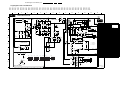
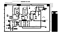
Detection by MPIF. ASUP status bit will set to
High if +8V falls below threshold level.
MIPS CORE
MPIF IRQ
CL 36532058_055.eps
011003
MPIF
+8V
MPIF_IRQ
ASUP
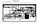
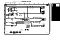
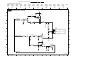
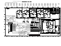
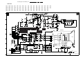
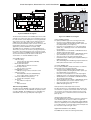
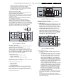
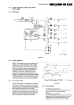
Figure 5-5 X-Ray Protection
CL 36532058_059.eps
091003
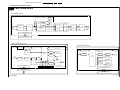
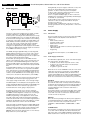
Figure 5-3 +8V Protection
5.7.4
DOP Related Protections
The uP reads every 200 ms the status register of the DOP (via
the I2C bus). If a protection signal is detected on one of the
inputs of the DOP, the relevant error bit in the register is set to
“high”. If this error bit is still “high” after 1 s, the OTC will store
the error code in the error buffer of the NVM and, depending on
the relevancy of the error bit, the set will either go into the
protection mode or not.
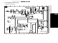
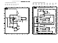
Beam Current Protection
A hardware interrupt is generated by the DOP core when the
current at the BCL input of the ADOC IC exceeds the limit.
To avoid false detection, the corresponding interrupt sub
routine checks the status of “BCF” bit in DOP core for five times
consecutively with an interval of 50 ms before triggering the
protection mode. Once the BCL protection status is confirmed,
the “PRD” bit has to be set to "1" by software. This enables an
automatic stop of the H-out via Slow Stop initiated by autoclearing the "DFL" bit. Now, the protection mode is activated.
-Ve
Threshold
Horizontal Fly Back Protection
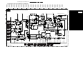
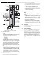
Hardware is employed for the detection of a horizontal
deflection fault. The DOP core generates a hardware interrupt
when consecutive three horizontal flyback pulses are not
received at the HFB input of the DOP block of the ADOC IC.
To avoid false detection, the corresponding interrupt sub
routine checks the status of “NOHFB” status bit in the DOP
core for five times consecutively with an interval of 50 ms
before triggering the protection mode. The response time for
this protection needed is 300 ms.
Switch
+Ve
Threshold
EHT-INFO
Signal
conditioning
BCL
Signal
conditioning
HFB_X-RAY-
-Ve
Threshold
NOHFB
Inverter
Switch
XPROT
MIPS CORE
Voltage
divider
Switch
+8V
When beam current is too high, at
defined level and will set BCL input
to=<1.2V, e7365.ADOC
This bit is checked
for 5 consecutive cycles to ensure
DOP
not caused
FLASH by other defect
(i.e flash-over).
MPIF
ADC
KEYBOARD
MPIF IRQ
CL 36532058_058.eps
011003
-Ve
Threshold
Switch
EHT-INFO
Signal
conditioning
BCL
Signal
conditioning
HFB_X-RAY-
-Ve
Threshold
NOHFB
Inverter
Switch
XPROT
MIPS CORE
Voltage
divider
Switch
+8V
ADOC
DOP for 5 cycles
Consecutively
check
FLASH
for the presence of flyback pulses
+Ve
Threshold
MPIF
ADC
KEYBOARD
MPIF IRQ
CL 36532058_056.eps
091003
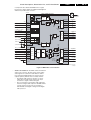
Figure 5-4 Horizontal Fly Back Protection
X-Ray Protection (Over Voltage, USA only)
Hardware is employed for the detection of X-ray fault. A
hardware interrupt is generated by the DOP core when the
"XPROT" input of ADOC IC is pulled "HIGH" (flyback pulses
are > 27 V_pp).
To avoid false detection, the corresponding interrupt sub
routine checks the status of “XPROT” bit in DOP core for five
times consecutively with an interval of 50 ms before triggering
the protection mode. It should be noted that the “XPROT”
status is not reset on reading. It should be cleared by the
software explicitly.
Once the XRAY protection status is confirmed, the “PRD” bit
has to be set to "1" by software. This enables an automatic stop
of the H-out via Slow Stop initiated by auto-clearing the DFL bit.
Now, the protection mode is activated.
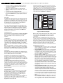
Figure 5-6 Beam Current Protection
Flash Protection
Flash detection is used to shutdown the set only if the Flash
occurs more than 5 times and is persistent. Therefore, this is a
method to protect the set from undue electrical stress because
of picture tube flashes. The flash detector circuitry uses the
"EHT_INFO" signal as input. Its output is connected to the
"FLASH" input of the DOP block of the ADOC.
When the "FLASH" input is pulled "HIGH", the ADOC’s
horizontal drive output stops immediately and the “FPR” status
bit of the DOP core is set to "1". The status is latched until
readout. With the absence of any other disturbances, the
horizontal drive output will restart after the "FLASH" input is
"LOW" again. No software interaction is required in this case.
The “FPR” bit has to be readout by polling at an interval of 500
ms. If the “FPR” status bit has been set to "1" for more than 5
times consecutively, then the protection mode has to be
triggered. Setting the “FPR” bit for less than 5 times by the
"FLASH" input does not need to trigger the protection mode
(shutting down of the H-drive should be enough).