1
PNX2000 User Manual
UM10105_1
Audio Video Input Processor
Rev. 1.0 — 28 November 2003
PNX2000
Philips Semiconductors
Audio Video Input Processor
UM10105_1
© Koninklijke Philips Electronics N.V. 2003. All rights reserved.
Rev. 1.0 — 28 November 2003
-ii
PNX2000
Philips Semiconductors
Audio Video Input Processor
Table of Contents
Chapter 1: Functional Specification
1.1
1.2
1.2.1
1.2.1.1
1.2.1.2
1.2.1.3
1.2.1.4
1.2.2
1.2.2.1
Introduction . . . . . . . . . . . . . . . . . . . . . . . . . . . . . 1-1
PNX2000 Feature Summary . . . . . . . . . . . . . 1-1
Video Features . . . . . . . . . . . . . . . . . . . . . . . . . . .
1FH Video . . . . . . . . . . . . . . . . . . . . . . . . . . . . . . .
2FH Video . . . . . . . . . . . . . . . . . . . . . . . . . . . . . . .
VBI Data Capture . . . . . . . . . . . . . . . . . . . . . . . . .
ITU656 output interface . . . . . . . . . . . . . . . . . . . .
Audio Features . . . . . . . . . . . . . . . . . . . . . . . . . . .
Demodulator and decoder . . . . . . . . . . . . . . . . .
1-1
1-1
1-1
1-1
1-2
1-2
1-2
1.2.2.2
1.2.2.3
1.2.2.4
1.2.2.5
1.2.2.6
1.3
1.4
Audio Multi Channel Decoder . . . . . . . . . . . . . . . 1-3
Volume and tone control . . . . . . . . . . . . . . . . . . . 1-3
Reflection and delay . . . . . . . . . . . . . . . . . . . . . . . 1-3
Psychoacoustic spatial algorithms,
downmix and split . . . . . . . . . . . . . . . . . . . . . . . . . 1-3
Interfaces and switching . . . . . . . . . . . . . . . . . . . 1-4
Functional Description. . . . . . . . . . . . . . . . . . . 1-4
Overview of Functional Partitioning . . . . . 1-6
Chapter 2: Control Interface
2.1
2.2
2.2.1
2.2.2
2.2.3
2.2.4
2.3
2.3.1
2.3.2
2.3.2.1
2.3.2.2
PNX2000 Control Interface . . . . . . . . . . . . . . 2-1
I2C Bus Interface . . . . . . . . . . . . . . . . . . . . . . . . 2-2
I2C Bus Features . . . . . . . . . . . . . . . . . . . . . . . . .
Allocated I2C Address . . . . . . . . . . . . . . . . . . . . .
I2C Register Access Protocol. . . . . . . . . . . . . . .
I2C Interface Block . . . . . . . . . . . . . . . . . . . . . . . .
2-2
2-2
2-2
2-6
BCU Module . . . . . . . . . . . . . . . . . . . . . . . . . . . . . 2-7
BCU Features . . . . . . . . . . . . . . . . . . . . . . . . . . . .
Registers . . . . . . . . . . . . . . . . . . . . . . . . . . . . . . . .
BCU Interrupt Status Register
(BCU_INT_STATUS) . . . . . . . . . . . . . . . . . . . . . .
BCU Interrupt Enable Register
(BCU_INT_ENABLE) . . . . . . . . . . . . . . . . . . . . . .
2-7
2-7
2-8
2.3.2.3
2.3.2.4
2.3.2.5
2.3.2.6
2.3.2.7
2.3.2.8
2.4
BCU Interrupt Status Set Command
(BCU_INT_SET) . . . . . . . . . . . . . . . . . . . . . . . . . . 2-9
BCU Interrupt Status Clear Command
(BCU_INT_CLEAR) . . . . . . . . . . . . . . . . . . . . . . . 2-9
BCU Bus Fault Status Register
(BCU_FAULT_STATUS) . . . . . . . . . . . . . . . . . . 2-10
BCU Bus Fault Address Register
(BCU_FAULT_ADDR) . . . . . . . . . . . . . . . . . . . . 2-10
BCU Time-Out Register (BCU_TOUT) . . . . . . 2-11
BCU Memory Coherency Register
(BCU_SNOOP) . . . . . . . . . . . . . . . . . . . . . . . . . . 2-11
Memory Map . . . . . . . . . . . . . . . . . . . . . . . . . . . . 2-12
2-8
Chapter 3: I2D
3.1
3.2
3.3
3.4
3.4.1
3.4.2
3.5
3.5.1
3.5.1.1
3.5.1.2
3.5.1.3
3.5.1.4
3.5.1.5
3.5.1.6
3.5.1.7
Introduction . . . . . . . . . . . . . . . . . . . . . . . . . . . . . 3-1
Functional Capabilities of the Links . . . . . 3-2
Transmitter . . . . . . . . . . . . . . . . . . . . . . . . . . . . . . 3-3
Receiver . . . . . . . . . . . . . . . . . . . . . . . . . . . . . . . . . 3-4
Transmitter / Receiver Transmission Modes. . 3-6
Data Rate and Timing Output Signals . . . . . . . 3-8
Configuration Registers. . . . . . . . . . . . . . . . . 3-9
I2D Register Map . . . . . . . . . . . . . . . . . . . . . . . .
I2D_RX_CTRL . . . . . . . . . . . . . . . . . . . . . . . . . .
I2D_RX_STATUS . . . . . . . . . . . . . . . . . . . . . . . .
I2D_REC_DEMUX_MODE . . . . . . . . . . . . . . . .
I2D _REC_SYNC_LOST. . . . . . . . . . . . . . . . . .
I2D _PRBS_STAT . . . . . . . . . . . . . . . . . . . . . . .
I2D _PRBS_CTRL . . . . . . . . . . . . . . . . . . . . . . .
I2D _INT_STATUS . . . . . . . . . . . . . . . . . . . . . . .
3-10
3-10
3-11
3-11
3-12
3-13
3-13
3-14
3.5.1.8
3.5.1.9
3.5.1.10
3.5.1.11
I2D _INT_ENABLE . . . . . . . . . . . . . . . . . . . . . . . 3-14
I2D _INT_CLEAR . . . . . . . . . . . . . . . . . . . . . . . . 3-15
I2D _INT_SET . . . . . . . . . . . . . . . . . . . . . . . . . . . 3-15
I2D _MOD_ID . . . . . . . . . . . . . . . . . . . . . . . . . . . 3-16
3.6
Interrupt Procedure . . . . . . . . . . . . . . . . . . . . 3-16
3.6.1
3.6.2
3.6.2.1
3.6.2.2
3.6.2.3
3.6.2.4
3.6.2.5
3.6.2.6
3.6.2.7
Interrupt Behaviour . . . . . . . . . . . . . . . . . . . . . . . 3-16
Software Action with Registers . . . . . . . . . . . . . 3-17
Start Up . . . . . . . . . . . . . . . . . . . . . . . . . . . . . . . . . 3-17
Normal Operation . . . . . . . . . . . . . . . . . . . . . . . . 3-18
Soft_reset . . . . . . . . . . . . . . . . . . . . . . . . . . . . . . . 3-18
Change of Source Selection . . . . . . . . . . . . . . . 3-18
Sync lost on a datalink (Out Of Sync) . . . . . . . 3-18
Missing data_valid pulses . . . . . . . . . . . . . . . . . 3-19
Test mode. . . . . . . . . . . . . . . . . . . . . . . . . . . . . . . 3-20
4.3.3
4.3.3.1
4.3.3.2
4.3.3.3
AGC Control Circuit . . . . . . . . . . . . . . . . . . . . . . 4-11
AGC Control Circuit for CVBS / Yyc path . . . . 4-11
AGC Control Circuit for Yyuv / Cyc Path . . . . 4-14
AGC Control Circuit for the Sync Path . . . . . . 4-22
Chapter 4: Video Processing (Viddec)
4.1
4.2
4.2.1
4.3
4.3.1
4.3.2
Overview . . . . . . . . . . . . . . . . . . . . . . . . . . . . . . . . . 4-1
Data input, Sample Rate Converter
and timing . . . . . . . . . . . . . . . . . . . . . . . . . . . . . . . 4-3
Short Description . . . . . . . . . . . . . . . . . . . . . . . . . 4-3
AGC . . . . . . . . . . . . . . . . . . . . . . . . . . . . . . . . . . . . . . 4-5
Short Description . . . . . . . . . . . . . . . . . . . . . . . . . 4-5
AGC Gain Stages . . . . . . . . . . . . . . . . . . . . . . . . . 4-6
4.4
4.4.1
Digital Multi Standard Decoder
(DMSD) . . . . . . . . . . . . . . . . . . . . . . . . . . . . . . . . . . 4-23
Y processing . . . . . . . . . . . . . . . . . . . . . . . . . . . . 4-25
UM10105_1
© Koninklijke Philips Electronics N.V. 2003. All rights reserved.
Rev. 1.0 — 28 November 2003
-iii
PNX2000
Philips Semiconductors
Audio Video Input Processor
4.4.2
4.4.2.1
4.4.2.2
4.4.2.3
4.4.3
4.4.3.1
4.4.4
4.4.5
4.4.5.1
4.4.5.2
4.4.5.3
4.4.6
4.4.6.1
Demodulator, Filtering (Combfilter)
and SECAM Decoder . . . . . . . . . . . . . . . . . . . .
Demodulator . . . . . . . . . . . . . . . . . . . . . . . . . . . .
Filtering . . . . . . . . . . . . . . . . . . . . . . . . . . . . . . . . .
SECAM decoder . . . . . . . . . . . . . . . . . . . . . . . . .
Color PLL and Delay Line . . . . . . . . . . . . . . . . .
Color PLL . . . . . . . . . . . . . . . . . . . . . . . . . . . . . . .
Color System Manager . . . . . . . . . . . . . . . . . . .
Signal controls, Macrovision and Debug . . . .
Signal Controls . . . . . . . . . . . . . . . . . . . . . . . . . .
Macrovision . . . . . . . . . . . . . . . . . . . . . . . . . . . . .
Debug & Control . . . . . . . . . . . . . . . . . . . . . . . . .
Sync Processing . . . . . . . . . . . . . . . . . . . . . . . . .
Horizontal Sync Processing 1 Fh
and Measurement/Control . . . . . . . . . . . . . . . .
4-27
4-28
4-29
4-32
4-33
4-33
4-38
4-46
4-46
4-47
4-49
4-50
4.4.6.2
4.4.6.3
4.4.6.4
4.4.6.5
4.4.6.6
4.4.7
4.4.8
4.4.9
4.4.9.1
4.4.9.2
4.4.9.3
Vertical Sync Processing 1 Fh . . . . . . . . . . . . . 4-58
Horizontal Sync Processing 2 Fh . . . . . . . . . . . 4-63
Vertical Sync Processing 2 Fh . . . . . . . . . . . . . 4-69
Fast Blanking / External 2 Fh Sync /
Clamp Info . . . . . . . . . . . . . . . . . . . . . . . . . . . . . . 4-74
YUV Switch + Formatter . . . . . . . . . . . . . . . . . . 4-78
Switching VIDDEC between 1Fh and 2Fh . . . 4-80
Use of interrupt bits . . . . . . . . . . . . . . . . . . . . . . . 4-81
Automatic selection of different
input signal formats . . . . . . . . . . . . . . . . . . . . . . . 4-82
CVBS or Y/C Input Selection . . . . . . . . . . . . . . 4-83
CVBS + RGB Insert via SCART . . . . . . . . . . . . 4-86
CVI Input Selection . . . . . . . . . . . . . . . . . . . . . . . 4-88
4-52
Chapter 5: Data Capture Unit
5.1
5.2
5.2.1
5.3
5.4
5.4.1
5.4.2
5.4.3
5.4.4
5.4.5
5.4.6
5.4.7
5.4.8
5.4.9
Summary of Functions . . . . . . . . . . . . . . . . . . 5-1
Block Diagram . . . . . . . . . . . . . . . . . . . . . . . . . . . 5-2
Block Description . . . . . . . . . . . . . . . . . . . . . . . . . 5-2
Design Specification. . . . . . . . . . . . . . . . . . . . . 5-3
Data Packet Formats . . . . . . . . . . . . . . . . . . . . 5-3
Status Bytes . . . . . . . . . . . . . . . . . . . . . . . . . . . . .
Euro WST, US WST and NABTS Data . . . . . .
WSS625 Data . . . . . . . . . . . . . . . . . . . . . . . . . . . .
WSS525 Data . . . . . . . . . . . . . . . . . . . . . . . . . . . .
VPS Data . . . . . . . . . . . . . . . . . . . . . . . . . . . . . . . .
Closed Caption . . . . . . . . . . . . . . . . . . . . . . . . . . .
Moji (Japanese Text) . . . . . . . . . . . . . . . . . . . . . .
VITC Data . . . . . . . . . . . . . . . . . . . . . . . . . . . . . . .
Open Data Types . . . . . . . . . . . . . . . . . . . . . . . . .
5-4
5-4
5-4
5-5
5-5
5-6
5-6
5-6
5-6
5.5
5.5.1
5.5.1.1
5.5.1.2
5.5.2
5.5.3
5.5.4
5.6
5.6.1
5.6.2
5.6.3
Packet Processing Capabilities . . . . . . . . . . 5-7
Magazine and Packet Number Decoding . . . . . 5-7
Input Data Format . . . . . . . . . . . . . . . . . . . . . . . . 5-7
Output Data Format . . . . . . . . . . . . . . . . . . . . . . . 5-7
Page Header Decoding . . . . . . . . . . . . . . . . . . . . 5-8
WSS525 CRC Checking . . . . . . . . . . . . . . . . . . . 5-8
Packet Validity Checking . . . . . . . . . . . . . . . . . . . 5-8
Registers . . . . . . . . . . . . . . . . . . . . . . . . . . . . . . . . . 5-9
5.6.4
5.6.5
5.6.6
DCR1: Data Capture Register (Write) . . . . . . . 5-10
DCR2: Data Capture Register 2 (Write) . . . . . 5-11
LCR2..LCR24: Line Control
Registers (Write) . . . . . . . . . . . . . . . . . . . . . . . . . 5-11
DCS: Data Capture Status (Read) . . . . . . . . . . 5-13
Interrupt Registers (Read/Write) . . . . . . . . . . . 5-14
MODULE_ID (Read). . . . . . . . . . . . . . . . . . . . . . 5-14
6.3.6
6.3.7
6.3.8
6.3.9
6.3.10
6.3.11
6.3.12
6.3.13
6.3.14
6.3.15
6.3.16
6.3.17
6.3.17.1
6.3.17.2
6.3.17.3
6.3.17.4
6.3.18
6.3.19
FIFO Register . . . . . . . . . . . . . . . . . . . . . . . . . . . 6-11
VF CONTROL Register . . . . . . . . . . . . . . . . . . . 6-11
VF SYNC Register . . . . . . . . . . . . . . . . . . . . . . . 6-11
FIELD 1 Register . . . . . . . . . . . . . . . . . . . . . . . . . 6-12
FIELD 2 Register . . . . . . . . . . . . . . . . . . . . . . . . . 6-12
VBI 1 Register . . . . . . . . . . . . . . . . . . . . . . . . . . . 6-12
VBI 2 Register . . . . . . . . . . . . . . . . . . . . . . . . . . . 6-13
VBI 3 Register . . . . . . . . . . . . . . . . . . . . . . . . . . . 6-13
VBI 4 Register . . . . . . . . . . . . . . . . . . . . . . . . . . . 6-13
PROG HBI Register . . . . . . . . . . . . . . . . . . . . . . 6-13
YUV Offset Register . . . . . . . . . . . . . . . . . . . . . . 6-14
Interrupt Registers . . . . . . . . . . . . . . . . . . . . . . . 6-14
INT_STATUS Register . . . . . . . . . . . . . . . . . . . 6-14
INT_ENABLE Register . . . . . . . . . . . . . . . . . . . 6-15
INT_CLEAR Register . . . . . . . . . . . . . . . . . . . . 6-15
INT_SET Register . . . . . . . . . . . . . . . . . . . . . . . 6-15
MODULE_ID Register . . . . . . . . . . . . . . . . . . . . 6-15
Debug Control Register . . . . . . . . . . . . . . . . . . 6-15
Chapter 6: ITU656
6.1.
6.2.
6.3.
6.3.1
6.3.2
6.3.2.1
6.3.2.2
6.3.2.3
6.3.2.4
6.3.2.5
6.3.2.6
6.3.2.7
6.3.2.8
6.3.2.9
6.3.2.10
6.3.2.11
6.3.2.12
6.3.2.13
6.3.2.14
6.3.3
6.3.4
6.3.5
ITU656 Formatter Overview . . . . . . . . . . . . . 6-1
ITU656 Formatter Data Interfaces . . . . . . . 6-2
Control Registers . . . . . . . . . . . . . . . . . . . . . . . 6-3
ITU656 Formatter Registers . . . . . . . . . . . . . . . . 6-3
CONFIG Register . . . . . . . . . . . . . . . . . . . . . . . . . 6-3
MODE . . . . . . . . . . . . . . . . . . . . . . . . . . . . . . . . . . 6-4
Columbus . . . . . . . . . . . . . . . . . . . . . . . . . . . . . . . . 6-4
VBI_CONTROL. . . . . . . . . . . . . . . . . . . . . . . . . . . 6-5
VBI_ONLY . . . . . . . . . . . . . . . . . . . . . . . . . . . . . . . 6-6
CVBS_COMPL . . . . . . . . . . . . . . . . . . . . . . . . . . . 6-6
UV_COMPL . . . . . . . . . . . . . . . . . . . . . . . . . . . . . . 6-6
DITHER . . . . . . . . . . . . . . . . . . . . . . . . . . . . . . . . . 6-6
DC_JUSTIFIED. . . . . . . . . . . . . . . . . . . . . . . . . . . 6-7
CLOCK_INVERT . . . . . . . . . . . . . . . . . . . . . . . . . 6-7
CLOCK_STUTTER . . . . . . . . . . . . . . . . . . . . . . . 6-8
PROGRESSIVE_MODE . . . . . . . . . . . . . . . . . . . 6-8
OUTPUT_TEST_MODE . . . . . . . . . . . . . . . . . . . 6-8
INPUT_TEST_MODE . . . . . . . . . . . . . . . . . . . . . 6-9
DVO_ENABLE . . . . . . . . . . . . . . . . . . . . . . . . . . . 6-9
Data Identification Register – VBI data. . . . . . . 6-9
Data Identification Register – HBI data . . . . . 6-10
CAPTURE Register . . . . . . . . . . . . . . . . . . . . . 6-10
6.4.
6.4.1
6.4.2
6.4.3
Video Line Interface Signal Structure . . . 6-17
PNX2000 (Mode 0) in Columbus Mode . . . . . 6-17
PNX2000 (Mode 1) in Columbus Mode . . . . . 6-18
PNX2000 (Mode 0) in PNX8550 mode . . . . . . 6-18
UM10105_1
© Koninklijke Philips Electronics N.V. 2003. All rights reserved.
Rev. 1.0 — 28 November 2003
-iv
PNX2000
Philips Semiconductors
Audio Video Input Processor
6.4.4
6.4.5
PNX2000 (Mode 1) in PNX8550 mode. . . . . . 6-19
PNX2000 (Mode 2) in PNX8550 mode. . . . . . 6-19
6.4.6
PNX2000 (Mode 3) in PNX8550 mode . . . . . . 6-19
7.8.14
7.8.14.1
7.8.14.2
7.8.14.3
Details of Operation . . . . . . . . . . . . . . . . . . . . . . 7-45
Search Procedures (ASD Mode) . . . . . . . . . . . 7-45
Using the SSS Mode . . . . . . . . . . . . . . . . . . . . . 7-52
Automatic Signal Switching and Routing . . . . 7-54
Chapter 7: Audio Processing
7.1
7.2
7.2.1
7.2.2
7.2.3
7.2.4
7.3
7.3.1
7.3.2
7.3.3
7.3.4
7.3.5
7.3.6
7.4
7.5
7.6
7.7
7.8
7.8.1
7.8.2
7.8.3
7.8.4
7.8.5
7.8.6
7.8.7
7.8.8
7.8.8.1
7.8.8.2
7.8.8.3
7.8.8.4
7.8.8.5
7.8.8.6
7.8.8.7
7.8.8.8
7.8.8.9
7.8.9
7.8.9.1
7.8.10
7.8.10.1
7.8.10.2
7.8.11
7.8.12
7.8.13
7.8.13.1
7.8.13.2
7.8.13.3
7.8.13.4
General Description . . . . . . . . . . . . . . . . . . . . . 7-1
Supported Standards . . . . . . . . . . . . . . . . . . . . 7-2
Analogue 2-carrier Systems . . . . . . . . . . . . . . . .
2-carrier Systems with NICAM . . . . . . . . . . . . . .
Satellite Systems . . . . . . . . . . . . . . . . . . . . . . . . .
BTSC/SAP, Japan (EIAJ) and FM Radio
Systems . . . . . . . . . . . . . . . . . . . . . . . . . . . . . . . . .
7-3
7-3
7-4
7-4
Features . . . . . . . . . . . . . . . . . . . . . . . . . . . . . . . . . 7-4
Demodulator and Decoder . . . . . . . . . . . . . . . . .
Audio Multi Channel Decoder. . . . . . . . . . . . . . .
Volume and Tone Control . . . . . . . . . . . . . . . . . .
Reflection and Delay . . . . . . . . . . . . . . . . . . . . . .
Psychoacoustic Spatial Algorithms,
Downmix and Split . . . . . . . . . . . . . . . . . . . . . . . .
Interfaces and Switching . . . . . . . . . . . . . . . . . . .
7-4
7-5
7-5
7-6
7-6
7-6
Functional Overview of the
Sound Core . . . . . . . . . . . . . . . . . . . . . . . . . . . . . . 7-7
Sound Core Control Interface . . . . . . . . . . . 7-8
I2S . . . . . . . . . . . . . . . . . . . . . . . . . . . . . . . . . . . . . . . 7-9
Digital-Analogue Converters . . . . . . . . . . . 7-11
Demdec DSP . . . . . . . . . . . . . . . . . . . . . . . . . . . . 7-11
DDEP in Brief . . . . . . . . . . . . . . . . . . . . . . . . . . .
What DDEP Does NOT Do . . . . . . . . . . . . . . . .
Design Considerations . . . . . . . . . . . . . . . . . . .
DDEP Basics and Usage . . . . . . . . . . . . . . . . .
DEMDEC Hardware Blocks and the
Sample Rate Problem . . . . . . . . . . . . . . . . . . . .
Signal Processing in DSP Software . . . . . . . .
SRC constraints . . . . . . . . . . . . . . . . . . . . . . . . .
The DDEP Control Register . . . . . . . . . . . . . . .
Mode Selection . . . . . . . . . . . . . . . . . . . . . . . . . .
Starting and Restarting . . . . . . . . . . . . . . . . . . .
DDEP Control Variables . . . . . . . . . . . . . . . . . .
Dependencies Between Variables in
the DDEPR . . . . . . . . . . . . . . . . . . . . . . . . . . . . .
Automute Function . . . . . . . . . . . . . . . . . . . . . . .
NICAM Configuration . . . . . . . . . . . . . . . . . . . . .
Amplitude and Noise Threshold Registers. . .
SAP Detection . . . . . . . . . . . . . . . . . . . . . . . . . . .
EIAJ Subcarrier Detection. . . . . . . . . . . . . . . . .
Other DEMDEC Control Options . . . . . . . . . . .
ADC Channel Control . . . . . . . . . . . . . . . . . . . .
Status Registers . . . . . . . . . . . . . . . . . . . . . . . . .
DEMDEC Status Register . . . . . . . . . . . . . . . . .
NICAM Status Registers . . . . . . . . . . . . . . . . . .
Noise Detection. . . . . . . . . . . . . . . . . . . . . . . . . .
Muting all DEMDEC Outputs . . . . . . . . . . . . . .
Using DDEP in a Set Design . . . . . . . . . . . . . .
Application Related Constant Settings . . . . . .
Prerequisites and User Interface . . . . . . . . . . .
Auto-tune Process . . . . . . . . . . . . . . . . . . . . . . .
Channel Switch Procedure . . . . . . . . . . . . . . . .
7-12
7-13
7-14
7-15
7-15
7-16
7-19
7-23
7-23
7-24
7-24
7-27
7-27
7-28
7-30
7-32
7-32
7-33
7-36
7-37
7-37
7-40
7-41
7-41
7-42
7-42
7-42
7-44
7-44
7.9
7.9.1
7.9.2
7.9.3
7.9.3.1
7.9.3.2
7.9.3.3
7.9.3.4
7.9.3.5
7.9.3.6
7.9.3.7
7.9.3.8
7.9.3.9
7.9.3.10
7.9.3.11
7.9.3.12
7.9.3.13
7.9.3.14
7.9.3.15
7.9.3.16
7.9.3.17
7.9.3.18
7.9.3.19
7.9.3.20
7.9.3.21
7.9.3.22
7.9.4
7.9.4.1
7.9.4.2
7.9.4.3
7.9.4.4
7.9.4.5
7.9.4.6
7.9.4.7
7.9.4.8
7.9.4.9
7.9.4.10
7.9.4.11
7.9.4.12
7.9.4.13
7.9.4.14
7.9.4.15
7.9.4.16
7.9.4.17
7.9.4.18
7.9.4.19
7.9.4.20
AUDIO-DSP . . . . . . . . . . . . . . . . . . . . . . . . . . . . . 7-59
Functional Overview . . . . . . . . . . . . . . . . . . . . . . 7-59
Loudspeaker Channel Sound Modes . . . . . . . 7-62
Comments about Function Control . . . . . . . . . 7-63
Automatic Volume Levelling (AVL) . . . . . . . . . 7-63
Virtual Dolby® Surround (VDS). . . . . . . . . . . . . 7-63
Virtual Dolby® Digital (VDD) . . . . . . . . . . . . . . . 7-64
Noise Sequencer for DPLII . . . . . . . . . . . . . . . . 7-65
Dolby® Pro Logic II® Function (DPLII) . . . . . . 7-65
Bass / Treble . . . . . . . . . . . . . . . . . . . . . . . . . . . . 7-67
Loudness . . . . . . . . . . . . . . . . . . . . . . . . . . . . . . . 7-69
Incredible Stereo (IStereo) . . . . . . . . . . . . . . . . 7-70
Incredible Mono (IMono) . . . . . . . . . . . . . . . . . . 7-72
Dynamic Ultra Bass (DUB) . . . . . . . . . . . . . . . . 7-73
Dynamic Bass Enhancement (DBE) . . . . . . . . 7-75
BBE® . . . . . . . . . . . . . . . . . . . . . . . . . . . . . . . . . . . 7-76
Bass Management . . . . . . . . . . . . . . . . . . . . . . . 7-77
Acoustical Compensation . . . . . . . . . . . . . . . . . 7-82
Equalizers . . . . . . . . . . . . . . . . . . . . . . . . . . . . . . . 7-83
Volume and Trim . . . . . . . . . . . . . . . . . . . . . . . . . 7-87
Beeper . . . . . . . . . . . . . . . . . . . . . . . . . . . . . . . . . . 7-87
Mono Signal for Cancellation in the
Voice Control IC . . . . . . . . . . . . . . . . . . . . . . . . . 7-87
Audio Monitor . . . . . . . . . . . . . . . . . . . . . . . . . . . . 7-87
Digital Output Crossbar . . . . . . . . . . . . . . . . . . . 7-87
Clip Management . . . . . . . . . . . . . . . . . . . . . . . . 7-88
Power On / Reset Specification . . . . . . . . . . . . 7-89
Audio Feature Specification . . . . . . . . . . . . . . . 7-89
Automatic Volume Levelling (AVL) . . . . . . . . . 7-90
Dolby® Pro Logic II® (DPLII) . . . . . . . . . . . . . . . 7-91
Virtual Dolby® Surround (VDS). . . . . . . . . . . . . 7-92
Virtual Dolby® Digital (VDD) . . . . . . . . . . . . . . . 7-93
Incredible Stereo (IStereo) . . . . . . . . . . . . . . . . 7-94
Incredible Mono (IMono) . . . . . . . . . . . . . . . . . . 7-95
Dynamic Ultra Bass (DUB) . . . . . . . . . . . . . . . . 7-96
Dynamic Bass Enhancement (DBE) . . . . . . . . 7-97
Loudness . . . . . . . . . . . . . . . . . . . . . . . . . . . . . . . 7-98
BBE® . . . . . . . . . . . . . . . . . . . . . . . . . . . . . . . . . . . 7-99
Bass and Treble . . . . . . . . . . . . . . . . . . . . . . . . 7-100
Bass Management . . . . . . . . . . . . . . . . . . . . . . 7-101
Delay Line Unit . . . . . . . . . . . . . . . . . . . . . . . . . 7-102
Pseudo Hall / Matrix . . . . . . . . . . . . . . . . . . . . . 7-103
Master Volume & Trim . . . . . . . . . . . . . . . . . . . 7-104
Volume and Balance for Auxiliary
Channels. . . . . . . . . . . . . . . . . . . . . . . . . . . . . . . 7-105
Level Adjust . . . . . . . . . . . . . . . . . . . . . . . . . . . . 7-106
Main Equalizer . . . . . . . . . . . . . . . . . . . . . . . . . . 7-107
Central Equalizer . . . . . . . . . . . . . . . . . . . . . . . . 7-108
Soft Mute . . . . . . . . . . . . . . . . . . . . . . . . . . . . . . 7-109
UM10105_1
© Koninklijke Philips Electronics N.V. 2003. All rights reserved.
Rev. 1.0 — 28 November 2003
-v
PNX2000
Philips Semiconductors
Audio Video Input Processor
7.9.4.21
7.9.4.22
7.9.4.23
Digital Input Crossbar . . . . . . . . . . . . . . . . . . . 7-110
Digital Output Crossbar . . . . . . . . . . . . . . . . . . 7-111
Audio Monitor . . . . . . . . . . . . . . . . . . . . . . . . . . 7-112
7.9.4.24
7.9.4.25
Beeper . . . . . . . . . . . . . . . . . . . . . . . . . . . . . . . . . 7-113
Noise Generator . . . . . . . . . . . . . . . . . . . . . . . . 7-114
Chapter 8: CGU
8.1
8.2
8.3
8.4
Clock Generation Unit (CGU) . . . . . . . . . . . .
PNX2000 Clock Requirements . . . . . . . . . . .
Crystal Oscillator Specification . . . . . . . . .
Phase Locked Loops . . . . . . . . . . . . . . . . . . . .
8.4.1
8.5
8.6
8.7
8-1
8.8
8-1
8-3
8.9
8-4
8.9.1
8.9.2
8.9.2.1
8.9.2.2
Power Saving Mode . . . . . . . . . . . . . . . . . . . . . . . 8-6
ITU Output Clock Generation . . . . . . . . . . . . 8-7
I2S Word Select (WS) Clock
Generation . . . . . . . . . . . . . . . . . . . . . . . . . . . . . . . 8-7
Clock Selection for 1fh and 2fh
Video Modes . . . . . . . . . . . . . . . . . . . . . . . . . . . 8-11
8.10
8.10.1
Clock Configuration and Status
Registers . . . . . . . . . . . . . . . . . . . . . . . . . . . . . . . . 8-11
Power-on and Reset . . . . . . . . . . . . . . . . . . . . 8-14
Reset Selection . . . . . . . . . . . . . . . . . . . . . . . . . . 8-14
Reset Operation and Power Management . . . 8-15
Power on/External Hard Reset . . . . . . . . . . . . 8-15
Soft Resets . . . . . . . . . . . . . . . . . . . . . . . . . . . . . . 8-15
Interrupts . . . . . . . . . . . . . . . . . . . . . . . . . . . . . . . 8-16
Top-Level Interrupt Status and
Control Registers . . . . . . . . . . . . . . . . . . . . . . . . 8-16
8.11
Miscellaneous Registers . . . . . . . . . . . . . . . . 8-17
9.7
9.8
9.9
9.10
9.11
DCU Register Settings . . . . . . . . . . . . . . . . . . . 9-8
I2D Settings . . . . . . . . . . . . . . . . . . . . . . . . . . . . . . 9-8
GTU Settings . . . . . . . . . . . . . . . . . . . . . . . . . . . . . 9-9
BCU Settings. . . . . . . . . . . . . . . . . . . . . . . . . . . . 9-10
MPIF Settings . . . . . . . . . . . . . . . . . . . . . . . . . . . 9-10
10.2
10.3
Full-power to Standby Sequence . . . . . . . 10-1
Standby to Full-power Sequence . . . . . . . 10-2
12.3
Signal Pins . . . . . . . . . . . . . . . . . . . . . . . . . . . . . 12-4
Chapter 9: Standards, Modes and Settings
9.1
9.2
9.3
9.4
9.5
9.6
Video Standards . . . . . . . . . . . . . . . . . . . . . . . . . 9-1
Data Capture Standards . . . . . . . . . . . . . . . . . 9-2
Audio Standards . . . . . . . . . . . . . . . . . . . . . . . . . 9-3
Display Modes . . . . . . . . . . . . . . . . . . . . . . . . . . . 9-4
ITU656 Formatter Settings . . . . . . . . . . . . . . . 9-5
Viddec Settings . . . . . . . . . . . . . . . . . . . . . . . . . . 9-6
Chapter 10: Device Initialization
10.1
Power-up Sequence (after Power-on
Reset) . . . . . . . . . . . . . . . . . . . . . . . . . . . . . . . . . . . 10-1
Chapter 11: Application Example
11.1
Application Example
(Single PNX2000) . . . . . . . . . . . . . . . . . . . . . . . 11-1
Chapter 12: PCB Layout Guidelines
12.1
12.2
Introduction . . . . . . . . . . . . . . . . . . . . . . . . . . . . 12-1
Power Supplies and Grounding . . . . . . . 12-1
12.2.1
12.2.2
PNX2000 . . . . . . . . . . . . . . . . . . . . . . . . . . . . . . . 12-1
PNX3000 . . . . . . . . . . . . . . . . . . . . . . . . . . . . . . . 12-2
12.3.1
12.3.2
12.3.3
Data-Link . . . . . . . . . . . . . . . . . . . . . . . . . . . . . . . 12-4
SAW Filters and IF Leads . . . . . . . . . . . . . . . . . 12-5
DACs Reference Voltages. . . . . . . . . . . . . . . . . 12-6
Chapter 13: Support Tools
13.1
Universal Register Debugger . . . . . . . . . . . 13-1
List of Figures
Chapter 1: Functional Specification
Figure 1:
PNX2000 Block Diagram . . . . . . . . . . . . . . . 1-5
UM10105_1
© Koninklijke Philips Electronics N.V. 2003. All rights reserved.
Rev. 1.0 — 28 November 2003
-vi
PNX2000
Philips Semiconductors
Audio Video Input Processor
Chapter 2: Control Interface
Figure 1:
Figure 2:
Figure 3:
Control Interface . . . . . . . . . . . . . . . . . . . . . . . 2-1
Single Write . . . . . . . . . . . . . . . . . . . . . . . . . . . 2-3
Single Read . . . . . . . . . . . . . . . . . . . . . . . . . . . 2-4
Figure 4:
Figure 5:
Burst Write . . . . . . . . . . . . . . . . . . . . . . . . . . . . 2-5
Burst Read . . . . . . . . . . . . . . . . . . . . . . . . . . . . 2-6
Figure 5:
Figure 6:
Figure 7:
Mode 0a Transmission. . . . . . . . . . . . . . . . . . 3-8
Mode 0b Transmission (Default) . . . . . . . . . 3-8
Mode 1 Transmission (2fh on Main
Channel, on sub is 1fh) . . . . . . . . . . . . . . . . . 3-9
Read Write and Control Flow . . . . . . . . . . . . 3-9
Chapter 3: I2D
Figure 1:
Figure 2:
Figure 3:
Figure 4:
Overview - I2D Transmitter/Receiver . . . . .
Overview - Datalink Modes, Transmitter
Side PNX3000 . . . . . . . . . . . . . . . . . . . . . . . .
Simplified Transmitter Side PNX3000 . . . .
Simplified Receiver Side PNX2000. . . . . . .
3-2
3-3
3-4
3-6
Figure 8:
Chapter 4: Video Processing (Viddec)
Figure 1:
Figure 2:
Figure 3:
Figure 4:
Figure 5:
Figure 6:
Figure 7:
Figure 8:
Figure 9:
Figure 10:
Figure 11:
Figure 12:
Figure 13:
Figure 14:
Figure 15:
Figure 16:
Block Diagram VIDeo DECoder . . . . . . . . . 4-2
Input and Sample Rate Conversion . . . . . . 4-3
Selection Input Data Streams for
VIDDEC in I2D . . . . . . . . . . . . . . . . . . . . . . . . 4-4
AGC Block Diagram. . . . . . . . . . . . . . . . . . . . 4-5
AGC Gain Stages . . . . . . . . . . . . . . . . . . . . . . 4-6
Input Format vs. Output Format of AGC . . 4-7
AGC Universal Programmable
Gain Stage. . . . . . . . . . . . . . . . . . . . . . . . . . . . 4-8
AGC Control Circuit CVBS/Yyc and
Yyuv/Cyc . . . . . . . . . . . . . . . . . . . . . . . . . . . . 4-11
Levels Before and After the AGC in
the Yyuv Path . . . . . . . . . . . . . . . . . . . . . . . . 4-16
Levels Before and After the AGC in
the Sync Path . . . . . . . . . . . . . . . . . . . . . . . . 4-18
AGC Control Circuit Sync . . . . . . . . . . . . . . 4-21
Levels Before and After Sync AGC. . . . . . 4-23
Block Diagram Digital Multi Standard
Decoder (DMSD) . . . . . . . . . . . . . . . . . . . . . 4-24
Y Processing . . . . . . . . . . . . . . . . . . . . . . . . . 4-25
Demodulator and Filtering . . . . . . . . . . . . . 4-28
Demodulator . . . . . . . . . . . . . . . . . . . . . . . . . 4-28
Figure 17:
Figure 18:
Figure 19:
Figure 20:
Figure 21:
Figure 22:
Figure 23:
Figure 24:
Figure 25:
Figure 26:
Figure 27:
Figure 28:
Figure 29:
Figure 30:
Figure 31:
Figure 32:
Figure 33:
Figure 34:
Figure 35:
Filters . . . . . . . . . . . . . . . . . . . . . . . . . . . . . . . 4-29
SECAM Detector . . . . . . . . . . . . . . . . . . . . . . 4-32
Color PLL and Delay Line . . . . . . . . . . . . . . 4-33
Color PLL . . . . . . . . . . . . . . . . . . . . . . . . . . . . 4-33
Delay Line . . . . . . . . . . . . . . . . . . . . . . . . . . . 4-37
Color System Manager . . . . . . . . . . . . . . . . 4-38
Color Decoder Output Control . . . . . . . . . . 4-46
Macrovision Detection . . . . . . . . . . . . . . . . . 4-47
Debug & Control . . . . . . . . . . . . . . . . . . . . . . 4-49
Sync Processing . . . . . . . . . . . . . . . . . . . . . . 4-50
Horizontal Sync Processing 1 Fh . . . . . . . . 4-52
Vertical Sync Processing 1 Fh . . . . . . . . . . 4-58
Horizontal Sync Processing 2 Fh . . . . . . . . 4-63
Vertical Sync Processing 2Fh . . . . . . . . . . . 4-69
Fast blanking, External 2 Fh
Composite Sync Input and Clamp Info . . . 4-74
YUV Switch and Formatter . . . . . . . . . . . . . 4-78
Block Diagram CVBS / YC Selection . . . . 4-83
Block diagram full SCART input
(CVBS + RGB + Fast Blanking) . . . . . . . . . 4-86
Block diagram CVI input selection . . . . . . . 4-88
Chapter 5: Data Capture Unit
Figure 1:
Block Diagram of the Data Capture Unit . . 5-2
Chapter 6: ITU656
Figure 1:
Figure 2:
Figure 3:
Figure 4:
Figure 5:
Figure 6:
Figure 7:
Formatter Block Diagram . . . . . . . . . . . . . . .
Insertion of HBI Data in ITU
Data Stream . . . . . . . . . . . . . . . . . . . . . . . . . .
Shifting of Bits in Pure Text Mode . . . . . . . .
Generation of Bytes in Nibble Mode . . . . . .
Dithering of 9 Bit Video Data to 8 Bits . . . .
ITU Output Data Stream
(CONFIG(10) = 0) . . . . . . . . . . . . . . . . . . . . .
ITU Output Data Stream
6-1
Figure 8:
6-5
6-7
Figure 9:
Figure 10:
Figure 11:
6-7
Figure 12:
6-5
6-6
UM10105_1
(CONFIG(10) = 1) . . . . . . . . . . . . . . . . . . . . . . 6-8
ITU Output Data Stream
(CONFIG(11) = 1) . . . . . . . . . . . . . . . . . . . . . . 6-8
Colour Bar Test Pattern . . . . . . . . . . . . . . . . . 6-8
Mono Bar Test Pattern . . . . . . . . . . . . . . . . . . 6-9
Insertion of VBI Data in ITU
Data Stream . . . . . . . . . . . . . . . . . . . . . . . . . . . 6-9
Insertion of HBI Data in ITU
Data Stream . . . . . . . . . . . . . . . . . . . . . . . . . . 6-10
© Koninklijke Philips Electronics N.V. 2003. All rights reserved.
Rev. 1.0 — 28 November 2003
-vii
PNX2000
Philips Semiconductors
Audio Video Input Processor
Chapter 7: Audio Processing
Figure 1:
Figure 2:
Figure 3:
Figure 4:
Figure 5:
Figure 6:
Figure 7:
Figure 8:
Figure 9:
Figure 10:
Figure 11:
Figure 12:
Figure 13:
Figure 14:
Figure 15:
Figure 16:
Figure 17:
Figure 18:
Figure 19:
Figure 20:
Figure 21:
Figure 22:
Figure 23:
Figure 24:
Figure 25:
Figure 26:
Figure 27:
Figure 28:
Figure 29:
Figure 30:
Figure 31:
Figure 32:
Figure 33:
Sound Functions . . . . . . . . . . . . . . . . . . . . . . 7-7
Philips I2S Format . . . . . . . . . . . . . . . . . . . . 7-10
Sony I2S Format . . . . . . . . . . . . . . . . . . . . . 7-10
Japanese Format . . . . . . . . . . . . . . . . . . . . . 7-11
Control Flow . . . . . . . . . . . . . . . . . . . . . . . . . 7-14
DEMDEC structure . . . . . . . . . . . . . . . . . . . 7-16
Signal Processing Modules and
SRC in DEMDEC DSP (Simplified). . . . . . 7-18
Switching and Matrixing in
Post-processing Block . . . . . . . . . . . . . . . . . 7-19
Spectra of TV HF Signals . . . . . . . . . . . . . . 7-47
B/G Search Procedure . . . . . . . . . . . . . . . . 7-49
D/K search procedure . . . . . . . . . . . . . . . . . 7-50
Search Procedure for M Standards . . . . . 7-52
Audio Backend Operation of PNX2000 . . 7-61
Virtual Dolby® Surround Left and
Right Output Signal . . . . . . . . . . . . . . . . . . . 7-64
Virtual Dolby® Digital Left and Right
Output Signal . . . . . . . . . . . . . . . . . . . . . . . . 7-65
Dolby® Pro Logic II® Function . . . . . . . . . . 7-67
Bass / Treble Function with Equal
Settings and Steps of 5dB . . . . . . . . . . . . . 7-68
Treble Function within Steps of 2dB.
The Bass Control is Set to Flat . . . . . . . . . 7-68
Bass Function within Steps of 2dB.
The Treble Control is Set to Flat . . . . . . . . 7-69
Loudness Curves for a MASTVOL
Range of 0 - -30dB (Step Width 1dB) . . . . 7-70
Block Diagram of the IStereo (RIS)
Module . . . . . . . . . . . . . . . . . . . . . . . . . . . . . . 7-71
Left/Right Output Signal of IStereo
Module (conditions 1 and 2) . . . . . . . . . . . . 7-71
Block Diagram of IMono Module . . . . . . . . 7-72
Block Diagram of the IMONO
Decorrelator Module . . . . . . . . . . . . . . . . . . 7-72
Left and Right Output Signal of the
IMono Module . . . . . . . . . . . . . . . . . . . . . . . . 7-73
Block Diagram of the DUB Function . . . . . 7-74
Download Procedure for DUB and
DBE Coefficients . . . . . . . . . . . . . . . . . . . . . 7-74
DUB Spectrum Plot . . . . . . . . . . . . . . . . . . . 7-75
Block Diagram of the Dynamic Bass
Enhancement (DBE) . . . . . . . . . . . . . . . . . . 7-76
DBE Response Curves for two
different Input Levels . . . . . . . . . . . . . . . . . . 7-76
Response Curve - Contour +9dB
@ 100Hz and Process +12dB @ 10kHz . 7-77
Overview of the PNX2000 Bass
Redirection . . . . . . . . . . . . . . . . . . . . . . . . . . 7-79
PNX2000 Bass Redirection in
Figure 34:
Figure 35:
Figure 36:
Figure 37:
Figure 38:
Figure 39:
Figure 40:
Figure 41:
Figure 42:
Figure 43:
Figure 44:
Figure 45:
Figure 46:
Figure 47:
Figure 48:
Figure 49:
Figure 50:
Figure 51:
Figure 52:
Figure 53:
Figure 54:
Figure 55:
Figure 56:
Figure 57:
Figure 58:
Figure 59:
Figure 60:
Figure 61:
Figure 62:
Figure 63:
Figure 64:
Figure 65:
Figure 66:
Figure 67:
Figure 68:
Figure 69:
UM10105_1
Configuration 1 . . . . . . . . . . . . . . . . . . . . . . . 7-80
PNX2000 Bass Redirection in
Configuration 2 . . . . . . . . . . . . . . . . . . . . . . . 7-80
PNX2000 Bass Redirection in
Configuration 3 . . . . . . . . . . . . . . . . . . . . . . . 7-81
PNX2000 Bass Redirection in
Configuration 4 (car application) . . . . . . . . 7-82
PNX2000 Bass Redirection
switched off . . . . . . . . . . . . . . . . . . . . . . . . . . 7-82
Block Diagram Acoustical
Compensation Filter . . . . . . . . . . . . . . . . . . . 7-83
Download Procedure - Equalizer
Coefficients after Power On Reset . . . . . . 7-84
Graphic Equalizer: 100Hz and 8kHz
Band (2dB Steps) and Envelope for
Max./Min. Gain . . . . . . . . . . . . . . . . . . . . . . . 7-85
Graphic Equalizer: 300Hz Band
(2dB Steps) . . . . . . . . . . . . . . . . . . . . . . . . . . 7-85
Graphic Equalizer: 1kHz Band
(2dB Steps) . . . . . . . . . . . . . . . . . . . . . . . . . . 7-86
Graphic Equalizer: 3kHz Band
(2dB Steps) . . . . . . . . . . . . . . . . . . . . . . . . . . 7-86
Clip Management . . . . . . . . . . . . . . . . . . . . . 7-89
AVL (Automatic Volume Levelling) . . . . . . 7-90
DPLII (Dolby® Pro Logic II®) . . . . . . . . . . . . 7-91
VDS (Virtual Dolby® Surround) . . . . . . . . . 7-92
VDD (Virtual Dolby® Digital) . . . . . . . . . . . . 7-93
IStereo (Incredible Stereo) . . . . . . . . . . . . . 7-94
IMono (Incredible Mono) . . . . . . . . . . . . . . . 7-95
DUB . . . . . . . . . . . . . . . . . . . . . . . . . . . . . . . . . 7-96
DBE . . . . . . . . . . . . . . . . . . . . . . . . . . . . . . . . . 7-97
Loudness . . . . . . . . . . . . . . . . . . . . . . . . . . . . 7-98
BBE® . . . . . . . . . . . . . . . . . . . . . . . . . . . . . . . . 7-99
Bass & Treble . . . . . . . . . . . . . . . . . . . . . . . 7-100
Bass Management . . . . . . . . . . . . . . . . . . . 7-101
Delay Line Unit . . . . . . . . . . . . . . . . . . . . . . 7-102
Pseudo Hall / Matrix . . . . . . . . . . . . . . . . . . 7-103
Master Volume & Trim . . . . . . . . . . . . . . . . 7-104
Volume and Balance for Auxiliary
Channels . . . . . . . . . . . . . . . . . . . . . . . . . . . 7-105
Level Adjust . . . . . . . . . . . . . . . . . . . . . . . . . 7-106
Main Equalizer . . . . . . . . . . . . . . . . . . . . . . . 7-107
Center Equalizer . . . . . . . . . . . . . . . . . . . . . 7-108
Soft Mute . . . . . . . . . . . . . . . . . . . . . . . . . . . 7-109
Digital Input Crossbar. . . . . . . . . . . . . . . . . 7-110
Digital Output Crossbar . . . . . . . . . . . . . . . 7-111
Audio Monitor . . . . . . . . . . . . . . . . . . . . . . . 7-112
Beeper . . . . . . . . . . . . . . . . . . . . . . . . . . . . . 7-113
Noise Generator . . . . . . . . . . . . . . . . . . . . . 7-114
© Koninklijke Philips Electronics N.V. 2003. All rights reserved.
Rev. 1.0 — 28 November 2003
-viii
PNX2000
Philips Semiconductors
Audio Video Input Processor
Chapter 8: CGU
Figure 1:
Figure 2:
Application Diagram: (a) Slave/Test Mode,
(b) Oscillation Mode . . . . . . . . . . . . . . . . . . . . 8-3
Simplified Schematic of PLL . . . . . . . . . . . . 8-4
Figure 3:
Figure 4:
Block Diagram - PNX2000 CGU . . . . . . . . . 8-6
Schematic of ITU Output Clock
Generation . . . . . . . . . . . . . . . . . . . . . . . . . . . . 8-7
Figure 4:
Figure 5:
Ground Shields . . . . . . . . . . . . . . . . . . . . . . . 12-6
PNX2000 DAC Connections . . . . . . . . . . . . 12-7
Table 2:
Interfaces . . . . . . . . . . . . . . . . . . . . . . . . . . . . . 1-6
2-9
Table 6:
Table 7:
Table 8:
Table 9:
Table 10:
BCU_FAULT_STATUS Register . . . . . . . . 2-10
BCU_FAULT_ADDR Register . . . . . . . . . . 2-10
BCU_TOUT Register . . . . . . . . . . . . . . . . . . 2-11
BCU_SNOOP Register . . . . . . . . . . . . . . . . 2-11
Memory Map . . . . . . . . . . . . . . . . . . . . . . . . . 2-12
Content of Data Links . . . . . . . . . . . . . . . . . . 3-7
Data Rate Output Signals . . . . . . . . . . . . . . . 3-9
I2D Register Summary . . . . . . . . . . . . . . . . 3-10
I2D_RX_CTRL . . . . . . . . . . . . . . . . . . . . . . . 3-10
I2D_RX_STATUS . . . . . . . . . . . . . . . . . . . . 3-11
I2D _REC_DEMUX_MODE . . . . . . . . . . . . 3-11
Demultiplexer Output with Mask
Selection . . . . . . . . . . . . . . . . . . . . . . . . . . . . 3-11
Table 8:
Table 9:
Table 10:
Table 11:
Table 12:
Table 13:
Table 14:
Table 15:
I2D_REC_SYNC_LOST . . . . . . . . . . . . . . . 3-12
I2D_PRBS_STAT . . . . . . . . . . . . . . . . . . . . . 3-13
I2D_PRBS_CTRL . . . . . . . . . . . . . . . . . . . . . 3-13
I2D _INT_STATUS . . . . . . . . . . . . . . . . . . . . 3-14
I2D _INT_ENABLE . . . . . . . . . . . . . . . . . . . . 3-14
I2D_INT_CLEAR . . . . . . . . . . . . . . . . . . . . . . 3-15
I2D _INT_SET . . . . . . . . . . . . . . . . . . . . . . . . 3-15
I2D _MOD_ID Block information . . . . . . . . 3-16
Chapter 9: Standards, Modes and Settings
Chapter 10: Device Initialization
Chapter 11: Application Example
Figure 1:
Typical TV Application Architecture . . . . . 11-2
Chapter 12: PCB Layout Guidelines
Figure 1:
Figure 2:
Figure 3:
Example of PCB Structure . . . . . . . . . . . . . 12-4
Suggested Data Link Routing . . . . . . . . . . 12-5
Track Length . . . . . . . . . . . . . . . . . . . . . . . . . 12-5
Chapter 13: Support Tools
Figure 1:
AMB - CE5109 . . . . . . . . . . . . . . . . . . . . . . . 13-2
List of Tables
Chapter 1: Functional Specification
Table 1:
Major Functions . . . . . . . . . . . . . . . . . . . . . . . 1-6
Chapter 2: Control Interface
Table 1:
Table 2:
Table 3:
Table 4:
Table 5:
BCU Register Map . . . . . . . . . . . . . . . . . . . . .
BCU_INT_STATUS register . . . . . . . . . . . . .
BCU_INT_ENABLE register . . . . . . . . . . . . .
BCU_INT_SET command. . . . . . . . . . . . . . .
BCU_INT_CLEAR command . . . . . . . . . . . .
2-7
2-8
2-8
2-9
Chapter 3: I2D
Table 1:
Table 2:
Table 3:
Table 4:
Table 5:
Table 6:
Table 7:
UM10105_1
© Koninklijke Philips Electronics N.V. 2003. All rights reserved.
Rev. 1.0 — 28 November 2003
-ix
PNX2000
Philips Semiconductors
Audio Video Input Processor
Chapter 4: Video Processing (Viddec)
Table 1:
Table 2:
Table 3:
Table 4:
Table 5:
Table 6:
Table 7:
Table 8:
Table 9:
Table 10:
Table 11:
Table 12:
Table 13:
Table 14:
Table 15:
Table 16:
Table 17:
Table 18:
Bit Description - AGC Gain Stages Address 0X7FF9xxx . . . . . . . . . . . . . . . . . . . 4-7
Bit Description - AGC Gain Control Address 0X7FF9xxx . . . . . . . . . . . . . . . . . . 4-12
Bit Description - AGC Control Circuit
for Yyuv / Cyc Path - Address 0X7FF9xxx4-15
AGC Yyuv / Cyc for YPrPb Signals. . . . . . 4-17
AGC Yyuv / Cyc for RGB Signals with
Sync on CVBS . . . . . . . . . . . . . . . . . . . . . . . 4-19
AGC Yyuv / Cyc for Cyc Signals . . . . . . . . 4-21
Bit Description - AGC Control Circuit
for the Sync Path - Address 0X7FF9xxx . 4-22
Bit Description - Y Processing Address 0X7FF9xxx . . . . . . . . . . . . . . . . . . 4-26
Bit Description - Demodulator Address 0X7FF9xxx . . . . . . . . . . . . . . . . . . 4-28
Bit Description - Filters - Address
0X7FF9xxx . . . . . . . . . . . . . . . . . . . . . . . . . . 4-30
DMSD_COL_DEC Control/Status Address 0X7FF9xxx . . . . . . . . . . . . . . . . . . 4-34
Range - dmsd_heuc . . . . . . . . . . . . . . . . . . 4-35
Bit Description - Delay Line Address 0X7FF9xxx . . . . . . . . . . . . . . . . . . 4-38
Bit Description, Color System Manager Control Bits - Address 0X7FF9xxx . . . . . . 4-40
Auto Mode - Settings . . . . . . . . . . . . . . . . . . 4-42
Full Search Loop . . . . . . . . . . . . . . . . . . . . . 4-43
Short Search Loop . . . . . . . . . . . . . . . . . . . . 4-43
Bit Descrition - Status Bits -
Table 19:
Table 20:
Table 21:
Table 22:
Table 23:
Table 24:
Table 25:
Table 26:
Table 27:
Table 28:
Table 29:
Table 30:
Table 31:
Table 32:
Table 33:
Address 0X7FF9xxx . . . . . . . . . . . . . . . . . . . 4-44
Bit Description - Signal Control Address 0X7FF9xxx . . . . . . . . . . . . . . . . . . . 4-46
Bit Description - Macrovision
Detection - Address 0X7FF9xxx . . . . . . . . 4-48
Bit Description - Debug and Control Address 0X7FF9xxx . . . . . . . . . . . . . . . . . . . 4-49
Bit Description - Horizontal Sync Address 0X7FF9xxx . . . . . . . . . . . . . . . . . . . 4-53
Status Bit Descrition - Vertical Sync Address 0X7 FF9xxx . . . . . . . . . . . . . . . . . . 4-59
Control Bit Description - Vertical
Sync - Address 0X7FF9xxx . . . . . . . . . . . . 4-60
Bit Description - Horiz. Sync Address 0X7FF9xxx . . . . . . . . . . . . . . . . . . . 4-64
Bit Description - Measurement /
Control - Address 0X7FF9xxx . . . . . . . . . . 4-67
Status Bit Description - Vert.Sync.
2Fh - Address OX7FF9xxx . . . . . . . . . . . . . 4-70
Control Bit Description - Vert.Sync.
2Fh - Address OX7FF9xxx . . . . . . . . . . . . . 4-71
Setting of Bits . . . . . . . . . . . . . . . . . . . . . . . . 4-73
Bit Description - Fast Blanking Address OX7FF9xxx . . . . . . . . . . . . . . . . . . 4-75
Bit Description - YUV Switch Address 0X7FF9xxx . . . . . . . . . . . . . . . . . . . 4-79
1Fh/2Fh Switching - Address
OX7FF7xxx . . . . . . . . . . . . . . . . . . . . . . . . . . 4-80
Interrupt Bits . . . . . . . . . . . . . . . . . . . . . . . . . 4-81
Chapter 5: Data Capture Unit
Table 1:
Table 2:
Table 3:
Table 4:
Table 5:
Table 6:
Table 7:
Table 8:
Table 9:
Table 10:
Table 11:
VBI Mode Text - Line Numbers . . . . . . . . . .
Data Packet Structure . . . . . . . . . . . . . . . . . .
Status Bytes . . . . . . . . . . . . . . . . . . . . . . . . . .
Status Bytes Bit Definitions . . . . . . . . . . . . .
Assembly of WSS625 Data into
Data Packet . . . . . . . . . . . . . . . . . . . . . . . . . . .
WSS625 Biphase Decoding . . . . . . . . . . . . .
WSS525 Data in Data Capture Memory . .
Assembly of VPS Data into Data Packet . .
VPS Biphase Decoding . . . . . . . . . . . . . . . . .
VITC Data Packet Contents . . . . . . . . . . . . .
Page Header Byte Sequence . . . . . . . . . . .
5-8
Table 13:
Table 14:
Table 15:
Table 16:
Table 17:
Table 18:
Table 19:
Table 20:
Table 21:
Table 22:
Register Address Map and
Reset Values . . . . . . . . . . . . . . . . . . . . . . . . . . 5-9
DCR1: Data Capture Register (Write) . . . . 5-10
Effect of DCR Register. . . . . . . . . . . . . . . . . 5-10
DCR2: Data Capture Register 2 (Write) . . 5-11
Effect of DCR2 Register . . . . . . . . . . . . . . . 5-11
Structure of LCR Registers . . . . . . . . . . . . . 5-11
Data Types . . . . . . . . . . . . . . . . . . . . . . . . . . . 5-12
DCS . . . . . . . . . . . . . . . . . . . . . . . . . . . . . . . . . 5-13
DCS Register Bit Definition . . . . . . . . . . . . . 5-13
Interrupt Register Bit Assignments . . . . . . 5-14
Module-ID Register Contents . . . . . . . . . . . 5-14
ITU656 Formatter Register Summary . . . . 6-3
CONFIG Register . . . . . . . . . . . . . . . . . . . . . . 6-3
Supported Video Standards . . . . . . . . . . . . . 6-4
Data Identification Register – VBI data . . . 6-9
Data Identification Register – HBI data . . 6-10
CAPTURE Register . . . . . . . . . . . . . . . . . . . 6-10
Table 7:
Table 8:
Table 9:
Table 10:
Table 11:
Table 12:
FIFO Register . . . . . . . . . . . . . . . . . . . . . . . . 6-11
VF Control Register . . . . . . . . . . . . . . . . . . . 6-11
VF Sync Register . . . . . . . . . . . . . . . . . . . . . 6-11
Field 1 Register . . . . . . . . . . . . . . . . . . . . . . . 6-12
Field 2 Register . . . . . . . . . . . . . . . . . . . . . . . 6-12
VBI 1 Register . . . . . . . . . . . . . . . . . . . . . . . . 6-12
5-3
Table 12:
5-3
5-4
5-4
5-4
5-4
5-5
5-5
5-5
5-6
Chapter 6: ITU656
Table 1:
Table 2:
Table 3:
Table 4:
Table 5:
Table 6:
UM10105_1
© Koninklijke Philips Electronics N.V. 2003. All rights reserved.
Rev. 1.0 — 28 November 2003
-x
PNX2000
Philips Semiconductors
Audio Video Input Processor
Table 13:
Table 14:
Table 15:
Table 16:
Table 17:
Table 18:
Table 19:
Table 20:
Table 21:
VBI 2 Register . . . . . . . . . . . . . . . . . . . . . . . .
VBI 3 Register . . . . . . . . . . . . . . . . . . . . . . . .
VBI 4 Register . . . . . . . . . . . . . . . . . . . . . . . .
PROG HBI Register . . . . . . . . . . . . . . . . . . .
YUV Offset Register . . . . . . . . . . . . . . . . . .
INT_STATUS Register . . . . . . . . . . . . . . . .
INT_ENABLE Register . . . . . . . . . . . . . . . .
INT_CLEAR Register . . . . . . . . . . . . . . . . .
INT_SET Register . . . . . . . . . . . . . . . . . . . .
6-13
6-13
6-13
6-13
6-14
6-14
6-15
6-15
6-15
Table 22:
Table 23:
Table 24:
Table 25:
Table 26:
Table 27:
Table 28:
Table 29:
Table 30:
MODULE_ID Register . . . . . . . . . . . . . . . . . 6-15
DEBUG Register . . . . . . . . . . . . . . . . . . . . . . 6-16
DEBUG Signals . . . . . . . . . . . . . . . . . . . . . . . 6-16
PNX2000 (Mode 0) in Columbus Mode . . 6-17
PNX2000 (Mode 1) in Columbus Mode . . 6-18
PNX2000 (Mode 0) in PNX8550 Mode . . . 6-18
PNX2000 (Mode 1) in PNX8550 Mode . . . 6-19
PNX2000 (Mode 2) in PNX8550 Mode . . . 6-19
PNX2000 (Mode 3 - Default) in
PNX8550 Mode . . . . . . . . . . . . . . . . . . . . . . . 6-19
Table 19:
Table 20:
Table 21:
Table 22:
Table 34:
Table 35:
Table 36:
Table 37:
Table 38:
Table 39:
DDEP_OPTIONS1_REG Register . . . . . . 7-33
SRC Configuration - up to sIx Channels . . 7-34
DD_OPTIONS2_REG Register . . . . . . . . . 7-35
ADC Channel Control Register
(DEM_ADC_SEL_REG, DD24) . . . . . . . . . 7-36
DEMDEC Status Register
(INF_MAIN_STATUS_REG, DD01) . . . . . 7-38
Generalized Stereo / Dual Flags . . . . . . . . 7-39
Deriving the Stereo / Dual Information
in Case of Forced Mono . . . . . . . . . . . . . . . 7-40
NICAM Status Register
(INF_NICAM_STATUS_REG, DD02) . . . . 7-40
Noise Detector Status Register
(INF_NOISELEVEL_REG, DD08. . . . . . . . 7-41
Noise Levels for Muting per Standard . . . . 7-42
Areas and ASD Settings . . . . . . . . . . . . . . . 7-44
Deciding for a Standard Group. . . . . . . . . . 7-49
DEMDEC Output Signals (not
Considering SRC Restriction) . . . . . . . . . . . 7-54
Overmodulation Adaptation Status
Register (INF_OVMADAPT_REG,
DD28) . . . . . . . . . . . . . . . . . . . . . . . . . . . . . . . 7-56
Register Map Overview of DEMDEC
DSP (High Latency Registers) . . . . . . . . . . 7-58
Loudspeaker Channel Sound Modes . . . . 7-62
Sound Modes . . . . . . . . . . . . . . . . . . . . . . . . 7-62
DUB - Coefficient . . . . . . . . . . . . . . . . . . . . 7-115
DBE - Coefficient . . . . . . . . . . . . . . . . . . . . 7-115
DBE - Coefficients for Maximum Boost . 7-116
Acoustical Compensation – Coefficient . 7-117
Table 9:
Table 10:
Table 13:
Table 11:
Table 12:
Table 15:
Table 16:
Table 14:
WS Clock Generation Modes . . . . . . . . . . . . 8-7
GP_WSSLAVEPLLCONTROL . . . . . . . . . . . 8-8
GP_WSPLLCONTROL . . . . . . . . . . . . . . . . . 8-9
GP_WSPLLMASTERSEL . . . . . . . . . . . . . . . 8-9
GP_WSPLLSLAVESEL . . . . . . . . . . . . . . . . . 8-9
GP_WS_FSCOUNTER . . . . . . . . . . . . . . . . 8-10
GP_WS_SAMPLERATE . . . . . . . . . . . . . . . 8-10
GP_WSPLLSTATUS . . . . . . . . . . . . . . . . . . 8-10
Chapter 7: Audio Processing
Table 1:
Table 2:
Table 3:
Table 4:
Table 5:
Table 6:
Table 7:
Table 8:
Table 9:
Table 10:
Table 11:
Table 12:
Table 13:
Table 14:
Table 15:
Table 16:
Table 17:
Table 18:
Frequency Modulation . . . . . . . . . . . . . . . . . . 7-3
Identification for A2 Systems . . . . . . . . . . . . 7-3
NICAM Standards . . . . . . . . . . . . . . . . . . . . . 7-3
FM Satellite Sound . . . . . . . . . . . . . . . . . . . . . 7-4
Frequency Modulation . . . . . . . . . . . . . . . . . . 7-4
Identification for BTSC/SAP, Japan
(EIAJ) and FM Radio Systems . . . . . . . . . . 7-4
Output Signal Restriction Depending
on SRCPREF . . . . . . . . . . . . . . . . . . . . . . . . 7-20
Active Output Signals Depending
on Standard and SRCPREF Selection . . . 7-21
Active SRC Channels per Configuration . 7-22
SRCPREF Selection Depending on
Desired Sources . . . . . . . . . . . . . . . . . . . . . . 7-22
Contents of DDEP Control Register
(DDEPR)2 (DD22) . . . . . . . . . . . . . . . . . . . . 7-25
Standard detection control bits in
ASD mode . . . . . . . . . . . . . . . . . . . . . . . . . . . 7-26
Static standard selection codes in
SSS mode . . . . . . . . . . . . . . . . . . . . . . . . . . . 7-26
NICAM Configuration Register
(NICAM_CFG_REG, DD21) . . . . . . . . . . . . 7-29
Magnitude Detection Register
(MAGDET_THR_REG, DD17) . . . . . . . . . . 7-30
Noise Automute Control Register, FMA2/
SAP (NMUTE_FMA2_SAP_REG, DD18 . 7-32
SAP Detection by magnitude and
noise detection . . . . . . . . . . . . . . . . . . . . . . . 7-32
Control Variables for EIAJ Subcarrier
Detection . . . . . . . . . . . . . . . . . . . . . . . . . . . . 7-33
Table 23:
Table 24:
Table 25:
Table 26:
Table 27:
Table 28:
Table 29:
Table 30:
Table 31:
Table 32:
Table 33:
Chapter 8: CGU
Table 1:
Table 2:
Table 3:
Table 4:
Table 5:
Table 6:
Table 7:
Table 8:
GTU Clock . . . . . . . . . . . . . . . . . . . . . . . . . . . .
Control Subsystem Clock . . . . . . . . . . . . . . .
Video Subsystem Clock . . . . . . . . . . . . . . . .
Sound Subsystem Clock . . . . . . . . . . . . . . . .
Primary Clock Settings . . . . . . . . . . . . . . . . .
Clocks Derived from Crystal . . . . . . . . . . . . .
PLL Control Signals . . . . . . . . . . . . . . . . . . . .
Summary of PLLs . . . . . . . . . . . . . . . . . . . . . .
8-1
8-1
8-2
8-3
8-4
8-4
8-5
8-5
UM10105_1
© Koninklijke Philips Electronics N.V. 2003. All rights reserved.
Rev. 1.0 — 28 November 2003
-xi
PNX2000
Philips Semiconductors
Audio Video Input Processor
Table 17:
Table 18:
Table 19:
Table 20:
Table 21:
Table 22:
Table 23:
Table 24:
Table 25:
Clock Selection . . . . . . . . . . . . . . . . . . . . . . .
GP_CLKEN . . . . . . . . . . . . . . . . . . . . . . . . . .
GP_CLKSEL . . . . . . . . . . . . . . . . . . . . . . . . .
GP_DISTRICONTROL . . . . . . . . . . . . . . . .
GP_TURBOPLLSEL . . . . . . . . . . . . . . . . . .
GP_TURBOPLLCONTROL . . . . . . . . . . . .
GP_TURBOPLLSTATUS . . . . . . . . . . . . . .
GP_SYSPLLSEL . . . . . . . . . . . . . . . . . . . . .
GP_SYSPLLCONTROL . . . . . . . . . . . . . . .
8-11
8-11
Table 26:
Table 27:
8-11
8-12
8-12
8-12
8-13
8-13
8-13
Table 28:
Table 29:
Table 30:
Table 31:
Table 32:
Table 33:
Table 34:
GP_SYSPLLSTATUS . . . . . . . . . . . . . . . . . 8-14
Internal POR Mode (select=1,
reset_n=0) . . . . . . . . . . . . . . . . . . . . . . . . . . . 8-14
External POR (select=0) . . . . . . . . . . . . . . . 8-14
POR Bypass Mode (select=reset_n) . . . . . 8-14
Soft Reset Control Bits. . . . . . . . . . . . . . . . . 8-15
GP_IRQ_STAT. . . . . . . . . . . . . . . . . . . . . . . 8-16
GP_IRQ_ENAB . . . . . . . . . . . . . . . . . . . . . . . 8-17
GP_IRQ_CLR . . . . . . . . . . . . . . . . . . . . . . . . 8-17
GP_IRQ_SET . . . . . . . . . . . . . . . . . . . . . . . . 8-17
Chapter 9: Standards, Modes and Settings
Table 1:
Table 2:
Table 3:
Table 4:
Table 5:
Table 6:
Table 7:
Table 8:
Table 9:
Table 10:
Table 11:
Table 12:
Table 13:
Table 18:
Table 14:
Table 15:
PAL Standard . . . . . . . . . . . . . . . . . . . . . . . . .
SECAM Standards . . . . . . . . . . . . . . . . . . . . .
NTSC Standards . . . . . . . . . . . . . . . . . . . . . .
ATSC Standards . . . . . . . . . . . . . . . . . . . . . .
NI Standards . . . . . . . . . . . . . . . . . . . . . . . . . .
Component Video Standards . . . . . . . . . . . .
Data Capture Standards . . . . . . . . . . . . . . . .
Audio Standards . . . . . . . . . . . . . . . . . . . . . . .
Display Modes . . . . . . . . . . . . . . . . . . . . . . . .
ITU656 Formatter Settings . . . . . . . . . . . . . .
Different Settings when Interfacing
to Columbus . . . . . . . . . . . . . . . . . . . . . . . . . .
Different Settings when using External
Syncs in Display Mode 1152i/50Hz . . . . . .
Viddec Settings . . . . . . . . . . . . . . . . . . . . . . . .
Negative Syncs Settings . . . . . . . . . . . . . . . .
Different Settings when Decoding
SECAM . . . . . . . . . . . . . . . . . . . . . . . . . . . . . .
Different Settings when Decoding YC . . . .
9-1
Table 16:
9-1
9-1
Table 17:
9-1
9-2
9-2
9-2
9-3
9-4
9-5
9-5
9-5
9-6
9-7
9-7
9-7
Table 19:
Table 20:
Table 21:
Table 22:
Table 23:
Table 24:
Table 25:
Table 26:
Table 27:
Table 28:
Table 29:
Table 30:
Additional Settings when
Interfacing to Columbus . . . . . . . . . . . . . . . . . 9-7
Additional/Different Settings using
External HV Syncs . . . . . . . . . . . . . . . . . . . . . 9-7
DCU Register Settings . . . . . . . . . . . . . . . . . . 9-8
Different Settings when Interfacing
to Columbus . . . . . . . . . . . . . . . . . . . . . . . . . . . 9-8
I2D Settings . . . . . . . . . . . . . . . . . . . . . . . . . . . 9-8
I2D Settings (YC) . . . . . . . . . . . . . . . . . . . . . . 9-8
Crystal Divider Settings . . . . . . . . . . . . . . . . . 9-9
SYSPLL and TURBOPLL Divider
Settings . . . . . . . . . . . . . . . . . . . . . . . . . . . . . . . 9-9
WSPLL Divider Settings - Auto
Master Mode . . . . . . . . . . . . . . . . . . . . . . . . . . 9-9
WSPLL Divider Settings - Master Mode . . . 9-9
Clock Settings for 1fh/2fh video modes . . 9-10
Enables/Resets . . . . . . . . . . . . . . . . . . . . . . . . . .
BCU Settings . . . . . . . . . . . . . . . . . . . . . . . . . 9-10
Recommended MPIF to AVIP Video
Settings . . . . . . . . . . . . . . . . . . . . . . . . . . . . . . 9-10
Chapter 10: Device Initialization
Chapter 11: Application Example
Chapter 12: PCB Layout Guidelines
Table 1:
Table 2:
Table 3:
Table 4:
PNX2000 3V3 Power Supplies . . . . . . . . .
PNX2000 1V8 Power Supplies . . . . . . . . .
PNX2000 Ground References . . . . . . . . . .
Non-connected Pins . . . . . . . . . . . . . . . . . .
12-1
12-1
12-2
Table 5:
Table 6:
Table 7:
PNX3000 8V / 5V Supplies . . . . . . . . . . . . . 12-2
PNX3000 5V Supplies . . . . . . . . . . . . . . . . . 12-2
PNX3000 Ground References . . . . . . . . . . 12-2
12-2
Chapter 13: Support Tools
UM10105_1
© Koninklijke Philips Electronics N.V. 2003. All rights reserved.
Rev. 1.0 — 28 November 2003
-xii
Chapter 1: Functional Specification
PNX2000 User Manual
Rev. 1.0 — 28 November 2003
1.1 Introduction
The PNX2000 is a companion IC device for the Nexperia DVP SOC PNX8550, to be
used in combination with the PNX3000.
It is aimed at mid and high-end analogue and hybrid TV sets, focusing on input
decoding of a single stream of analogue audio and a single stream of analogue video
signals. In addition, the PNX2000 is used for decoding and the presentation of all
audio output streams in the system.
1.2 PNX2000 Feature Summary
1.2.1 Video Features
• Automatic Gain Control (AGC) to correct amplitude errors at input source.
• Synchronization identification (used for channel search).
• Sync processing for 1FH and 2FH video input source.
• Standard detection of PAL, NTSC or SECAM and various 1FH/2FH component
video input sources.
1.2.1.1
1FH Video
• Color decoding (ITU-601) for PAL, NTSC or SECAM input sources.
• 2D comb filter.
• Supports component video sources with sync on CVBS or green.
• Fastblank insertion of RGB signals onto CVBS input.
1.2.1.2
2FH Video
• Supports various progressive and interlaced component video sources.
• Synchronization of video sources with sync on Y or external H/V inputs.
1.2.1.3
VBI Data Capture
• Decodes 525 line standards – WST, WSS, VPS, CC, VITC.
PNX2000
Philips Semiconductors
Functional Specification
• Decodes 625 line standards – WST, WSS, CC, VITC.
1.2.1.4
ITU656 output interface
• Video and VBI formatted into an ITU-style output data stream, compliant to ITU656/1364 (exception being the use of a data valid signal).
• Interfaces to PNX8550 IC.
• Supports CVBS/C mode to interface to external picture improvement devices.
1.2.2 Audio Features
1.2.2.1
Demodulator and decoder
• Demodulator and Decoder Easy Programming (DDEP)
• Auto standard detection (ASD)
• Static Standard Selection (SSS)
• DQPSK demodulation for different standards, simultaneously with 1-channel FM
demodulation
• NICAM decoding (B/G, I, D/K and L standard)
• Two-carrier multistandard FM demodulation (B/G, D/K and M standard)
• Decoding for three analogue multi-channel systems (A2, A2+ and A2*) and
satellite sound
• Adaptive de-emphasis for satellite FM
• Optional AM demodulation for system L, simultaneously with NICAM
• Identification A2 systems (B/G, D/K and M standard) with different identification
time constants
• FM pilot carrier present detector
• Monitor selection for FM/AM DC values and signals, with peak and quasi peak
detection option
• BTSC MPX decoder
• SAP decoder
• dbx noise reduction
• Japan (EIAJ) decoder
• FM radio decoder
• Soft-mute for DEMDEC outputs DEC, MONO and SAP
• FM overmodulation adaptation option to avoid clipping and distortion
UM10105_1
© Koninklijke Philips Electronics N.V. 2003. All rights reserved.
Rev. 1.0 — 28 November 2003
1-2
PNX2000
Philips Semiconductors
Functional Specification
• Sample rate conversion (SRC) for up to three demodulated terrestrial audio
signals. It is possible to process SCART signals together with demodulated
terrestrial signals.
1.2.2.2
Audio Multi Channel Decoder
• Dolby® Pro Logic® II Surround (DPL2) — Registered Trademark of Dolby®
Laboratories
• Six channel processing for Main Left and Main Right, Subwoofer, Center,
Surround Left and Surround Right
1.2.2.3
Volume and tone control
• Automatic Volume Level (AVL) control
• Smooth volume control
• Master volume control and Balance
• Soft-mute
• Loudness
• Bass, Treble
• Dynamic Bass Enhancement (DBE)
• Dynamic Ultra Bass (DUBII)
• Non processed subwoofer
• 5 band equalizer
• Acoustical compensation
• Programmable beeper
• Noise generator for loudspeaker level trimming
1.2.2.4
Reflection and delay
• Dolby® Pro Logic® Delay
• Pseudo hall/matrix function
1.2.2.5
Psychoacoustic spatial algorithms, downmix and split
• Incredible Mono
• Incredible Stereo
• Virtual Dolby® Surround (VDS 522,523)
• Virtual Dolby® Digital (VDD 522,523)
• Bass Redirection according to Dolby® specifications
UM10105_1
© Koninklijke Philips Electronics N.V. 2003. All rights reserved.
Rev. 1.0 — 28 November 2003
1-3
PNX2000
Philips Semiconductors
Functional Specification
1.2.2.6
Interfaces and switching
• Digital audio input interface (stereo I2S input interface)
• Digital audio output interface (stereo I2S output interface)
• Digital crossbar switch for all digital signal sources and destinations
• Output crossbar for exchange of channel processing functionality
• Voice recognition output interface (stereo I2S output interface)
• Audio monitor for level detection
• 8 audio DACs for six channel loudspeaker outputs and stereo headphones output
• 4 audio DACs for stereo SCART output and stereo LINE output.
• Serial data link interface for interfacing with the analogue multi-purpose interface
IC PNX3000.
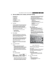
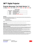
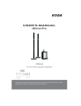
1.3 Functional Description
The following figure shows a block diagram of the PNX2000 device.
UM10105_1
© Koninklijke Philips Electronics N.V. 2003. All rights reserved.
Rev. 1.0 — 28 November 2003
1-4
PNX2000
Philips Semiconductors
Functional Specification
DLINK1 DLINK2
Audio data SIF or L/R
DLINK3
Video data CVBS, Y/C, YUV
54MHz clock 27/54 Msamples/sec
I2D
I2C
Bus
HSYNC
I2C
VIDDEC
HSYNC/VSYN
INT
GTU
DCU
13.5/27
MHz
Xtal
Clocks
ITU-656
6x I2S
Inputs
Sound
6x I2S
Outputs
X4
PNX3000
interface
(2 stereo/4
mono)
Figure 1:
PI-Bus
SDACS
X6
X2
ITU-656
1fh/2fh
10-bit data
BCU
PNX2000 Block Diagram
UM10105_1
© Koninklijke Philips Electronics N.V. 2003. All rights reserved.
Rev. 1.0 — 28 November 2003
1-5
PNX2000
Philips Semiconductors
Functional Specification
1.4 Overview of Functional Partitioning
The following table illustrates how the major functions are mapped to hardware
blocks.
Table 1: Major Functions
Function
Block
High speed data-link
2
I D
Video Decoder Processor VIDDEC
Description
Receives data in 3 streams from PNX3000
Decodes and processes CVBS, YUV or Y/C in YUV
stream
Serial Interface
I2C
To access all the internal registers
Global Task Unit
GTU
Generates all the internal clocks, Reset and Power
management
TV Sound Decoder
DEMDEC
DSP
Demodulation, decoding of terrestrial TV audio
standards
Audio Processor
AUDIO
DSP
Processing analogue and digital audio sources
Data Capture Unit
DCU
Acquires VBI data (Teletext, CC, VPS) and formats
in a stream
Formatter Unit
ITU-656
Formats YUV, VBI data and CVBS data in ITU-656
Bus Control Unit
BCU
Bus arbitration among all the internal blocks
Table 2: Interfaces
Interface Description
I2C
The PNX2000 IC is controlled using an I2C bus. It performs like an I2C-bus to PIbus bridge, i.e. translates I2C-slave received commands to PI-bus master
commands.
I2D
Receives data in three streams from PNX3000.
I2S
Serial digital audio interface (6 stereo inputs and 6 stereo outputs) for connection
to other devices that support the I2S standard. Can be used to receive decoded
sound from a multi-channel digital audio decoder, provide additional ADCs and
DACs, or loop audio signals through an external processor or delay line.
ITU656
Mainly intended to transfer output data stream externally to the PNX8550 but the
output data stream could also be readable by other ITU 656 input devices that
implement data valid signalling
DACS
Digital-analogue converters used to generate analogue outputs from Sound Core
UM10105_1
© Koninklijke Philips Electronics N.V. 2003. All rights reserved.
Rev. 1.0 — 28 November 2003
1-6
Chapter 2: Control Interface
PNX2000 User Manual
Rev. 1.0 — 28 November 2003
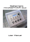
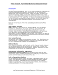
2.1 PNX2000 Control Interface
The PNX2000 device is controlled via an I2C interface. Internally, an I2C-to-PI Bus
bridge converts I2C accesses into read and write transactions on the internal PI-Bus.
This PI-Bus provides access to the control and status registers for all the modules in
the PNX2000 design. The operation of the internal PI bus is controlled by the BCU
block.
BCU
ITU656
Registers
PI Bus
I 2D
Registers
I 2S
Registers
I2C-Bus
I2C/PI Bus
Bridge
VIDDEC
Registers
2
I C Slave
PI Bus
Master
PI Bus
GTU
Registers
DEMDEC
Registers
Audio DSP
Registers
DCU
Registers
Figure 1:
Control Interface
PNX2000
Philips Semiconductors
Control Interface
2.2 I2C Bus Interface
2.2.1 I2C Bus Features
The I2C module has the following features:
• 7-bit I2C slave address.
• LSB of I2C address selectable from external pin, to allow two PNX2000 devices
to coexist on a shared I2C bus.
• Auto increment addressing to allow sequential (burst) register accesses with no
address transmission overhead.
• PI Bus data width 32 bits.
• PI bus address width 32 bits.
• I2C data transmitted in big endian format (MSB transmitted first).
• Up to 400 kHz I2C bus speed.
2.2.2 Allocated I2C Address
The 7-bit I2C address of the PNX2000 device is:
A6
A5
A4
A3
A2
A1
A0
RW
1
0
0
0
1
0
X
X
Bit A0 can be selected via the external pin I2CADR. This pin defaults to pull-down (A0
= 0) if left unconnected.
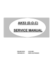
2.2.3 I2C Register Access Protocol
The following diagrams illustrate the procedure used to access register locations over
the I2C bus.
UM10105_1
© Koninklijke Philips Electronics N.V. 2003. All rights reserved.
Rev. 1.0 — 28 November 2003
2-2
PNX2000
Philips Semiconductors
Control Interface
Single Write
I2C Master
I2C Slave (PNX2000)
I2C Start Condition
Device Address
(r/w = 0)
4 bytes subaddress
(= PI bus address)
4 bytes data
I2C Stop Condition
Figure 2:
Single Write
UM10105_1
© Koninklijke Philips Electronics N.V. 2003. All rights reserved.
Rev. 1.0 — 28 November 2003
2-3
PNX2000
Philips Semiconductors
Control Interface
Single Read
I2C Master
I2C Slave (PNX2000)
I2C Start Condition
Device Address
(r/w = 0)
4 bytes subaddress
(= PI bus address)
I2C Repeat -Start
Condition
Device Address
(r/w = 1)
4 bytes data
I2C Stop Condition
Figure 3:
Single Read
UM10105_1
© Koninklijke Philips Electronics N.V. 2003. All rights reserved.
Rev. 1.0 — 28 November 2003
2-4
PNX2000
Philips Semiconductors
Control Interface
Burst Write
I2C Master
I2C Slave (PNX2000)
I2C Start Condition
Device Address
(r/w = 0)
4 bytes subaddress
(= PI bus address)
4 bytes data
4 bytes data
…(as many 4-byte
words as desired)
PNX2000 will
internally increment
the PI-Bus address
for each data word
I2C Stop Condition
Figure 4:
Burst Write
UM10105_1
© Koninklijke Philips Electronics N.V. 2003. All rights reserved.
Rev. 1.0 — 28 November 2003
2-5
PNX2000
Philips Semiconductors
Control Interface
B u rst R ead
I 2 C M aster
I 2 C S lave (PN X 2000)
I 2 C S tart C ondition
D evice A ddress
(r/w = 0)
4 bytes subaddress
(= P I bus address)
R epeat- S tart
C ondition
D evice A ddress
(r/w = 1)
4 bytes data
4 bytes data … (as
m any 4- byte data
w ords as desired).
T he P N X 2000 w ill
internally increm ent
the P I- B us address
for each data w ord.
I 2 C S top C ondition
Figure 5:
Burst Read
2.2.4 I2C Interface Block
The I2C interface module contains no software-accessible status or configuration
registers.
If the internal PI-Bus locks up, the I2C interface will lock the external I2C bus by
holding the SCL signal low. The only way to break the lockup is to reset the entire
PNX2000 device. In order to avoid this condition, the BCU timeout register should be
configured by software early in the PNX2000 initialization process.
UM10105_1
© Koninklijke Philips Electronics N.V. 2003. All rights reserved.
Rev. 1.0 — 28 November 2003
2-6
PNX2000
Philips Semiconductors
Control Interface
The PNX2000 I2C module will not respond to a ‘general call’ on the I2C-bus, i.e. when
a slave address of 0000000 is sent by a master. In case of any illegal address,
transmission of the data that follows is not acknowledged, and the transmission is
aborted.
The I2C-bus slave devices are capable of operating at a maximum speed of
400 kbits/s in accordance with the I2C fast-mode specification.
2.3 BCU Module
2.3.1 BCU Features
The BCU module performs the following functions:
• Address space mapping and slave selection
• Bus error notification and logging
• Bus timeout monitoring, with software programmable timeout threshold
• Interrupt generation on bus error and timeout
2.3.2 Registers
The BCU contains eight software accessible registers which are listed in
the following table. Note that the base address of the BCU is 0x07fe8000.
The “reset” values given in the tables in the following subsections correspond to the
state of a variable after PI-Bus reset.
Table 1: BCU Register Map
Offset from BCU
Register Name
Slave address
Description
BCU_INT_STATUS
0x00
BCU interrupt status
BCU_INT_SET
0x04
BCU interrupt status set
BCU_INT_CLEAR
0x08
BCU interrupt status clear
BCU_FAULT_STATUS
0x0C
BCU bus fault status
BCU_FAULT_ADDRESS
0x10
BCU bus fault address
BCU_INT_ENABLE
0x14
BCU interrupt enable
BCU_TOUT
0x18
BCU time-out control
BCU_SNOOP
0x1C
BCU memory coherency control
UM10105_1
© Koninklijke Philips Electronics N.V. 2003. All rights reserved.
Rev. 1.0 — 28 November 2003
2-7
PNX2000
Philips Semiconductors
Control Interface
2.3.2.1
BCU Interrupt Status Register (BCU_INT_STATUS)
This register contains the BCU interrupt status variables. It is read-only. The register
also controls the bus fault logging process.
Table 2: BCU_INT_STATUS register
Bits
Variable
Reset
R/W
31:2
RSD
-
-
1
BCU_TO
0
R
0
BCU_BE
0
R
RSD
Reserved bits, will produce zero on a read action and ignored on write
action
BCU_TO
Time-out error:
0: no time-out error has occurred. Fault logging enabled if BCU_BE=0
and BCU_TO=0.
1: time-out error has occurred. Fault logging stopped. Registers
BCU_FAULT_STATUS and BCU_FAULT_ADDRESS contain valid
information. Depending on the state of the BCU_INT_EN flag in the
BCU_INT_ENABLE register, an interrupt request may be generated.
BCU_BE
Bus error:
0: no bus error has occurred. Fault logging enabled if BCU_TO=0 and
BCU_BE=0.
1: bus error has occurred. Fault logging stopped. Registers
BCU_FAULT_STATUS and BCU_FAULT_ADDRESS contain valid
information. Depending on the state of the BCU_INT_EN flag in the
BCU_INT_ENABLE register, an interrupt request may be generated.
2.3.2.2
BCU Interrupt Enable Register (BCU_INT_ENABLE)
This register contains a variable to enable/disable BCU interrupt request generation.
It is read/writable. Note that this register does not have two enable bits (i.e.
corresponding to the two status bits in the BCU_INT_STATUS, BCU_INT_SET, and
BCU_INT_CLEAR registers). One enable bit controls the generation of both bus error
and timeout interrupts.
Table 3: BCU_INT_ENABLE register
Bits
Variable
Reset
R/W
31: 1
RSD
-
R
0
BCU_INT_EN
0
R/W
RSD
Reserved bits, produce zero on read action and ignored on
write.
BCU_INT_EN BCU Interrupt Enable
0: disable BCU interrupt request.
UM10105_1
© Koninklijke Philips Electronics N.V. 2003. All rights reserved.
Rev. 1.0 — 28 November 2003
2-8
PNX2000
Philips Semiconductors
Control Interface
1: enable BCU interrupt request. An interrupt request is
generated when the BCU_TO and/or BCU_BE flags in the
BCU_INT_STATUS register are set.
2.3.2.3
BCU Interrupt Status Set Command (BCU_INT_SET)
A write action to this address location allows to set variables in the
BCU_INT_STATUS register. A read action returns 0. The BCU_INT_SET command
is provided for diagnostic purposes only.
Table 4: BCU_INT_SET command
Bits
Variable
Reset
R/W
31:2
RSD
-
R
1
BCU_TO_SET
-
W
0
BCU_BE_SET
-
W
RSD
Reserved bits, produce zero on read action and ignored on a write.
BCU_TO_SET
Time-out interrupt set:
0: no effect
1: set BCU_TO variables
BCU_BE_SET
Bus error interrupt set:
0: no effect
1: set BCU_BE variables
2.3.2.4
BCU Interrupt Status Clear Command (BCU_INT_CLEAR)
A write action to this address location allows to clear variables in the
BCU_INT_STATUS register. A read action returns 0.
Table 5: BCU_INT_CLEAR command
Bits
Variable
Reset
R/W
31:2
RSD
-
R
1
BCU_TO_CLEAR
-
W
0
BCU_BE_CLEAR
-
W
RSD
Reserved bits, produce zero on read action and ignored on a write.
BCU_TO_CLEAR Time-out interrupt clear:
0: no effect
1: set BCU_TO variables
BCU_BE_CLEAR Bus error interrupt clear:
0: no effect
1: clear BCU_BE variables
UM10105_1
© Koninklijke Philips Electronics N.V. 2003. All rights reserved.
Rev. 1.0 — 28 November 2003
2-9
PNX2000
Philips Semiconductors
Control Interface
2.3.2.5
BCU Bus Fault Status Register (BCU_FAULT_STATUS)
This register captures status information on the PI-Bus operation that incurred a bus
error or time-out. The register content is valid only when the BCU_TO and/or
BCU_BE flags in BCU_INT_STATUS are set. The register is read-only. Note that the
PNX2000 design has only one bus master - the I2C interface.
Table 6: BCU_FAULT_STATUS Register
Bits
Variable
Reset
R/W
31:8
RSD
-
-
7
BCU_MASTER*
X
R
6
BCU_LOCK
X
R
5
BCU_READ
X
R
4:0
BCU_OPC
X
R
[6-1]
* BCU_MASTER is not relevant for PNX2000
[6-2]
X undefined
RSD (Reserved bits) will produce zero on a read action and will be ignored on a write
action.
BCU_LOCK
LOCK status of failed bus operation:
0: LOCK = 0
1: LOCK = 1
BCU_READ
Data direction of failed bus operation:
0: write operation
1: read operation
BCU_OPC
Opcode of failed bus operation:
refer to PI-Bus specification [2] for opcode definition.
2.3.2.6
BCU Bus Fault Address Register (BCU_FAULT_ADDR)
This register captures the address in a PI-Bus operation that incurred a bus error or
time-out. The register content is valid only when the BCU_TO and/or BCU_BE flags
in BCU_INT_STATUS are set. The register is read-only.
Table 7: BCU_FAULT_ADDR Register
Bits
Variable
Reset
R/W
31:2
BCU_ADDR
X
R
1:0
RSD
0
R
[7-1]
X undefined
BCU_ADDR
failed bus operation address
RSD
reserved bits, produce zero on a read action ignored on a write
UM10105_1
© Koninklijke Philips Electronics N.V. 2003. All rights reserved.
Rev. 1.0 — 28 November 2003
2-10
PNX2000
Philips Semiconductors
Control Interface
2.3.2.7
BCU Time-Out Register (BCU_TOUT)
This register defines the PI-Bus time-out threshold. It is read/writable. Although this
register has a default value of 0, it should be written with the value 0x800 soon after
reset, to prevent potential PI-Bus and I2C bus lockups.
Table 8: BCU_TOUT Register
Bits
Variable
Reset
R/W
31: 0
BCU_TO_THRESHOLD
0
R/W
BCU_TO_THRESHOLD Time-out threshold:
0: never time-out
1: time-out after 1st data cycle in bus operation
4294967295: time-out after 4294967295th data cycle in bus
operation
2.3.2.8
BCU Memory Coherency Register (BCU_SNOOP)
This register enables/disables the start of the memory coherency protocol. This
register should be left at the default value, as the PNX2000 device does not support
cache-coherent memory access.
Table 9: BCU_SNOOP Register
Bits
Variable
Reset
R/W
31:3
RSD
X
R
2
BCU_SNOOP_MASTERS
0
R/W
1
BCU_SNOOP_WRITE
0
R/W
0
BCU_SNOOP_READ
0
R/W
[9-1]
X undefined
RSD
Reserved bits, produce zero on a read action ignored on a
write
BCU_SNOOP_MASTERS Bit not relevant for PNX2000. To be left at default value.
BCU_SNOOP_WRITE
Bit not relevant for PNX2000. To be left at default value.
BCU_SNOOP_READ
Bit not relevant for PNX2000. To be left at default value.
UM10105_1
© Koninklijke Philips Electronics N.V. 2003. All rights reserved.
Rev. 1.0 — 28 November 2003
2-11
PNX2000
Philips Semiconductors
Control Interface
2.4 Memory Map
The PNX2000 memory map is given in the following table. Note that the address
ranges allocated to each block are not fully occupied by addressable register
locations.
Table 10: Memory Map
PI Bus Address
Block
0x07F0.0000
AUDIO_DSP
0x07F3.FFFF
0x07F8.0000
DEMDEC DSP
0x07FB.FFFF
0x07FE.8000
BCU
0x07FE.8FFF
0x07FF.5000
DCU
0x07FF.5FFF
0x07FF.7000
GPR(GTU)
0x07FF.7FFF
I2D
0x07FF.8000
0x07FF.8FFF
0x07FF.9000
VIDDEC
0x07FF.9FFF
0x07FF.A000
ITU656
0x07FF.AFFF
UM10105_1
© Koninklijke Philips Electronics N.V. 2003. All rights reserved.
Rev. 1.0 — 28 November 2003
2-12
Chapter 3: I2D
PNX2000 User Manual
Rev. 1.0 — 28 November 2003
3.1 Introduction
This section provides an overview of the I2D link and how it may be applied. It gives
the user a guide to use the datalink and its functions. The purpose of the link is
transmitting data in three streams from the PNX3000 to the PNX2000. The use of
serial data connections results in a considerable reduction in pin count and the
number of connection wires that are needed between both IC’s.
The communication between one datalink transmitter and one datalink receiver
consists of two signals, a data signal and a strobe signal. The strobe signal contains
the data, bit-sync and word-sync information. For optimal EMC performance both
data and strobe are low voltage differential signals. The voltage swing on the wires is
about 300mV.
In the PNX3000 the video and audio data to be transmitted is multiplexed in an output
register of 42 bits. The content of that 42-bit register is serial transmitted on one of the
three datalinks. In the PNX2000 the serial data is demultiplexed into parallel streams.
With a software selection in the PNX3000 you can choose which data you want to set
in the output register for the datalink and in the PNX2000 you have to make a
selection which data from the datalink you want to use. The data on the datalink is
divided in several groups of signals (video, audio and strobe_signals). It is important
that the transmitter and receiver are in the same transmitting mode.
PNX2000
Philips Semiconductors
I2D
PNX3000
CVBS/Y-prim
CVBS/Y-prim
PNX2000
1
Clock
Domain
Separators
D
ICLP
Clk
54M
nd
2nd SIF/ 2 SIF
EXT
ICLP
Yyu
Clk
54MH
1
A
D
ICL
ICLP
U
A
V
D
ICL
1
Clk
27/54M
L1/AMint
DataLi
D
D
1+
D
I2D
Receiver
1+
4
54MHz
L1
L2
4
1+
1+
D
R2
L2
10
4
SIF
4
DataLink
CVBSs
1+
I2D
Receiver
HV
1+
Xtal Clk
54MHz
HV sec
Demux and
Formatter
2
Clk
6.75MH
MIC/L2/PipM
UV
D
DataLink
Yyuv/C
10
10
4
A
R1/AMext
VAL
D
D
Clk
27/54M
10
10
54MHz
D
PI toDTL
Adapter
CVBS/
I2D
Receiver
4
Data Link
CVBS_sec
A
DTL
Controller
Demux_mode
DataLink
1
Data Link 2
C
Data Link
A
Conf.
Registers
54MHz
A
MIC/R2
Figure 1:
D
2
Overview - I2D Transmitter/Receiver
3.2 Functional Capabilities of the Links
The I2D link has the following characteristics.
• The datalink runs at 297MHz / 594 Mbs.
• The driver rise/fall time is around 200 pS.
• The datalink uses differential signals.
The receiver has an internal termination resistor of 100Ω differential connected.
• The differential threshold is 50 mV.
• The signalling voltages are between 200 – 500 mV.
• The datalink traces, both pairs should be of equally length and are internally
terminated with 100Ω (The PCB-lines also characteristic).
UM10105_1
© Koninklijke Philips Electronics N.V. 2003. All rights reserved.
Rev. 1.0 — 28 November 2003
3-2
PNX2000
Philips Semiconductors
I2D
• The max length of the datalink tracks is 20 cm (equal length), normal advice is 5
cm maximal.
• The maximal capacitance on the line is around 15 pF.
3.3 Transmitter
In the PNX3000 the data coming from the A/D converters (digital video and audio) is
multiplexed and put in data words. Each data word on the data links consists of 44
bits (4 video samples of 10 bits each, 2 audio samples of 2 bits and 2 word-sync bits).
The word clock is 13.5MHz. The data rate on each of the three data links is 44 bits/
cycle*13.5*106 Cycle/s=594Mbit/s. Figure 2 shows which signals are digitized and
these can be sent to the digital video processor by the datalink. Mode 0 is the 1fh
mode and mode 1 is the 2fh mode (for datalink 1 and 2). Both modes can transferred
up to three video channels plus one sound IF signal and two L+R audio signals over
the data links simultaneously. For detailed transmission information see Table 2.
Mod Application
0 T
1 YUV 2
Data
Data
Video
Audio Video
CVBS/Yp Cpri L R Yyu U,
Yyuv
L R U
V
Yyuvn Yyuvn+1 Yyuvn+2 Yyuvn+3
Figure 2:
L1
Audio
L R
L R
Data
Video
Test
SI X X
SI X X
R1
Overview - Datalink Modes, Transmitter Side PNX3000
UM10105_1
© Koninklijke Philips Electronics N.V. 2003. All rights reserved.
Rev. 1.0 — 28 November 2003
3-3
PNX2000
Philips Semiconductors
I2D
CVBS/Y-prim
CVBS/Y-prim
10
A
C
D
Data
Link 1
ICLP
DataLink
Clk
54MHz
2nd SIF/ 2nd SIF EXT
DataLink
10
A
CVBS_sec
54MHz 297MHz
D
ICLP
Clk
54MHz
Yyuv
Data
Link 3
DataLink
10
A
D
ICLP
ICLP
Clk
27/54MHz
U
54MHz 297MHz
A
V
D
10
Data
Link 2
DataLink
ICLP
Clk
27/54MHz
L1/AMint
A
R1/AMext
D
2
54MHz 297MHz
Clk
6.75MHz
MIC/L2/PipM
A
2
MIC/R2
D
Clk
6.75MHz
Figure 3:
Simplified Transmitter Side PNX3000
3.4 Receiver
The I2D datalink is intended for the communication between the PNX3000 and the
PNX2000.
The I2D receiver module consists of three datalink receivers, and three Data Strobe
receivers. The data receiver regenerates the serial data bit-streams, and converts
them to parallel words of 42 bits (picture 4x10 bits and 2 bits of audio). When the data
is ready for output a valid Word Sync pulse is generated in the I2D receiver module.
The Word Sync pulses are used by the clock domain separator to take over the 42
bits wide data from the I2D receivers to the PNX2000 clock domain.
UM10105_1
© Koninklijke Philips Electronics N.V. 2003. All rights reserved.
Rev. 1.0 — 28 November 2003
3-4
PNX2000
Philips Semiconductors
I2D
The clock domain separator module converts the data from the transmitter clock
(13.5 or 27 MHz) domain (PNX3000) to the PNX2000 clock (13.5 / 54 MHz) domain.
There is a clock domain separator necessary because the signals in the PNX3000
are processed via different paths and then multiplexed on a serial data line with a
Data Strobe (and Word Sync). This leads to a static but unknown phase difference
between the PNX2000 and PNX3000 clock. In addition, the duration of the serial data
differs according the link length and group of data on the link and the different
processing in the PNX3000. That is why a clock domain separator is necessary.
The data from the clock domain separator module is passed to the de-multiplexer
module. This module formats the data into several audio and video streams (parallel
data) together with accompanying VALid pulses derived from the clock domain
separator (ready for takeover) to the Viddec and Demdec modules.
When the expected Word Sync pulse is not detected in the I2D receiver, the clock
domain separator still generates a DV pulse. The previous data is still on the parallel
output lines of the I2D receiver. When the Word Sync pulse is not detected, the
counter counts the missing DataValids. This internal counting continues until it
reaches the DV_MISS_MAX value (Table 8). When the limit of DV_MISS_MAX is
reached, an interrupt DVx_MISS_STAT is generated, ref to Table 11 for more details,
and a synchronization action must follow. When the limit is reached the internal
counter is frozen.
When the max value of DV_MISS_MAX is not reached and a Word Sync pulse
arrives in the receiver window, the counter DV_MISS_MAX is reset.
When there is a situation in which the expected Word Sync pulse is detected in the
I2D receiver, but not within the data valid window (receiver window) of the Clock
domain Separator, the pulse is Out Of Window (OOW). The clock domain separator
generates a Data Valid (DV) pulse on the time that the clock domain separator
expects to receive a Word Sync pulse from the receiver. The data can still be valid if
the pulse comes to early, but if the pulse comes to late, the previous data can be on
the output when the clock domain separator takes the data over. When the Word
Sync pulse is out of his window detected, it generates an Out Of Window (OOW)
pulse (referring to I2D _REC_SYNC_LOST). This Out Of Window pulse increments
the counter (it counts the OOW pulses), the counter value itself cannot be read. This
counting continues till it reaches the OOW_MAX value (register I2D
_REC_SYNC_LOST). When the limit of OOW_MAX is reached, an interrupt
SYNCx_LOST_STAT is generated, ref to I2D _INT_STATUS for more details, and a
synchronization action must follow. When the max value of OOW_MAX is not
reached and a Word Sync pulse arrives in the receiver window, the counter
OOW_MAX is reset.
At the end of the receiver is a de-multiplexer, the de-multiplexer reformats the data
into several audio and video streams (parallel data) to the Viddec and Demdec.The
functional block diagram of the receiver is shown in Figure 4.
UM10105_1
© Koninklijke Philips Electronics N.V. 2003. All rights reserved.
Rev. 1.0 — 28 November 2003
3-5
PNX2000
Philips Semiconductors
I2D
PI bus
Clock
Domain
Separators
DTL
Control
Conf.
Registers
I2D REC INT
DataLink
DataLink
I2D
Receiver
Demux_mode
DV
10+1
CVBS/Yyc
10+1
Yyuv/Cyc
VAL
DV
10+1
42
UV
10+1
42
CVBSsub
DV
DataLink
1+1
DV
I2D
Receiver
PI toDTL
Adapter
L1
1+1
42
L2
42
DV
1+1
R2
1+1
DV
L2
10+1
42
SIF
42
1+1
I2D
Receiver
HV
1+1
DataLink
HV_sec
Xtal Clk
54MHz
Demux and
Formatter
Figure 4:
Simplified Receiver Side PNX2000
3.4.1 Transmitter / Receiver Transmission Modes.
The data from the PNX3000 can be sent in two modes (0, 1) to the receiver in the
PNX2000. Table 1 describes the data that can be extracted from the datalink. The
transmitter in the PNX3000 has to be set by the external I2C communication link. The
microprocessor in the PNX2000 transmits the mode settings and other multiplexer
settings by the I2C bus to the PNX3000. The receiver in the PNX2000 has to be
configured in the same mode by the PI bus in the PNX2000. In Table 1 is described
the dataflow and possible modes on each link. The software for the receiver runs in
the MIPS processor in the PNX2000. The software takes care of the boot sequences,
interrupts and the use of the data on the datalink.
When the transmitter is in mode 0 (all three transmitters are in mode 0), the receiver
has the possibility to extract data in mode 0a en 0b (for all three links together). This
is possible due to the group of 42 bits send together, see Figure 1 and Table 2.
UM10105_1
© Koninklijke Philips Electronics N.V. 2003. All rights reserved.
Rev. 1.0 — 28 November 2003
3-6
PNX2000
Philips Semiconductors
I2D
When Viddec uses Y and C from mode 0 datalink 1, it can’t use YUV from datalink 2
(no sync available, they use the same bus in the demultiplexer output). If the Viddec
use YUV from datalink 2 (input from RGB in PNX3000) it use the CVBS datalink 1 for
sync.
Table 1: Content of Data Links
Datalink 1
mode setting
Bits
mode reg
value
41
40
39:30
29:20
CVBS or Yn+1
19:10
C
9:0
CVBS or Yn
mode 0a
0x0
R1
L1
Cn+1
mode 0b
0x1
R1
L1
-
CVBS or Yn+1
-
CVBS or Yn
mode 1
0x2
R1
L1
Yyuvn+3
Yyuvn+2
Yyuvn+1
Yyuvn
Datalink 2
mode setting
n
Bits
mode reg
value
41
40
39:30
29:20
19:10
9:0
mode 0a
0x0
R2
L2
-
-
-
-
mode 0b
0x1
R2
L2
Vn
Yyuvn+1
Un
Yyuvn
mode 1
0x2
R2
L2
Vn+2
Un+2
Vn
Un
40
39:30
29:20
19:10
9:0
CVBSsecn+1
SIFn
CVBSsecn
Datalink 3
mode setting
Bits
mode reg
value
41
mode 0a
0x0
HVsec
HV
SIFn+1
mode 0b
0x1
HVsec
HV
SIFn+1
CVBSsecn+1
SIFn
CVBSsecn
mode 1
0x2
HVsec
HV
SIFn+1
CVBSsecn+1
SIFn
CVBSsecn
A CVBS or Y signal may be connected to the inputs of the PNX3000. The type of
signal on Datalink 1, in Mode 0 (a or b) is not known, but the preferred is shown bold
underlined.
If from datalink 1 (mode 0b) the CVBS is used, via fast insertion the Viddec can use
the YUV (1fH-mode) signals from datalink2 if the signal contains a sync signal.
Figure 5, Figure 6 and Figure 7 show the use modes (video) in the receiver at the
output of the multiplexer.
UM10105_1
© Koninklijke Philips Electronics N.V. 2003. All rights reserved.
Rev. 1.0 — 28 November 2003
3-7
PNX2000
Philips Semiconductors
I2D
Data Link 1
Demux
Y/C or CVBS
VIDDEC
CVBS
VIDDEC
Data Link 2
Data Link 3
Figure 5:
Mode 0a Transmission
Data Link 1
Demux
YUV
Data Link 2
Data Link 3
Figure 6:
Mode 0b Transmission (Default)
Data Link 1
Demux
Data Link 2
Y
VIDDEC
UV
Data Link 3
Figure 7:
Mode 1 Transmission (2fh on Main Channel, on sub is 1fh)
The control software has to set the right settings in the MPIF and AVIP.
3.4.2 Data Rate and Timing Output Signals
The output rate of the data from the datalink receiver is shown in Table 2.
The HV_PRIM and HV_SEC are for the horizontal and vertical sync for the primary
and secondary channel (timing pulses in IF part). These are clamping signals, which
are coming from the VIDDEC. The frequency of the signals is dependent of the select-
UM10105_1
© Koninklijke Philips Electronics N.V. 2003. All rights reserved.
Rev. 1.0 — 28 November 2003
3-8
PNX2000
Philips Semiconductors
I2D
ed mode. These signals are not needed for I2D link.
Table 2: Data Rate Output Signals
Pin Name
Sample Rate (Msamples/s)
1FH
2FH
CVBS_YYC_OUT
27
-
YYUV_CYC_OUT
27
54
UV_OUT
27
54
CVBS_SEC_OUT
27
-
LEFT1_OUT
6.75
RIGHT1_OUT
6.75
LEFT2_OUT
6.75
RIGHT2_OUT
6.75
HV_OUT
54
HV_SEC_OUT
54
SIF_OUT
27
All data is generated on the negative edge of the 54 MHz clock.
3.5 Configuration Registers.
The I2D configuration registers are used to control the I2D receiver module. For
description of the de-multiplexer outputs see following figure.
Figure 8:
Read Write and Control Flow
UM10105_1
© Koninklijke Philips Electronics N.V. 2003. All rights reserved.
Rev. 1.0 — 28 November 2003
3-9
PNX2000
Philips Semiconductors
I2D
The I2D configuration register block contains the control registers which are used to
configure the I2D receiver block, address decoder and two state machines. One to
synchronise the write request and the register write enable, and the other one to
synchronise the read request and read enable.
3.5.1 I2D Register Map
This section provides information on the I2D configuration. Each of the registers
within the receiver block is described separately below. The base address for the I2D
is set to 0x07FF8000 (32 bits), the last 3 digits (12 bits) are for the I2D control
register.
Table 3: I2D Register Summary
Name
Access Type
Width
Address
Reset Value
I2D _RX_CTRL
Read/Write
32
0x000
0x1
I2D _RX_STATUS
Read
32
0x004
0x1
I2D _MOD_ID
Read
32
0xFFC
0x01410000
I2D _INT_SET
Write
32
0xFEC
0x00000000
I2D _INT_CLEAR
Write
32
0xFE8
0x00000000
I2D _INT_ENABLE
Read/Write
32
0xFE4
0x00000000
I2D _INT_STATUS
Read
32
0xFE0
0x0000002a
I2D _REC_DEMUX_MODE
Read/Write
32
0x018
0x0001fff9
I2D _PRBS_CTRL
Read/Write
32
0x024
0x00000000
I2D _PRBS_STAT
Read/Write
32
0x020
0x00000078
I2D _REC_SYNC_LOST
Read/Write
32
0x01C
0x000003e8
3.5.1.1
I2D_RX_CTRL
Table 4: I2D_RX_CTRL
Bits
Name
Access Type
Reset Value
Description
31..01
RSD_31 To 1
Reserved
0x0
Reserved
0
RX_APPL_PD
Read/Write
0x1
Power down for analogue receiver in application mode.
'0' : The analogue receiver is active (normal mode)
'1' : The analogue receiver is in power down mode (For
PNX2000 sleep/coma modes)
This is the bit to wake up or set the I2D receiver in power down mode.
UM10105_1
© Koninklijke Philips Electronics N.V. 2003. All rights reserved.
Rev. 1.0 — 28 November 2003
3-10
PNX2000
Philips Semiconductors
I2D
3.5.1.2
I2D_RX_STATUS
Table 5: I2D_RX_STATUS
Bits
Name
Access Type
Reset Value
Description
31..01
RSD_31 To 1
Reserved
0x0
Reserved
0
PD_STAT_RX
Read
0x1
Power down status of analogue datalink receiver.
'0' : The receiver is active (normal mode)
'1' : The receiver is in power down mode
This is a status bit to verify if the datalink receiver is really activated or if it was still in
power down mode. When the I2D_RX_CTRL bit 0 differs from the I2D_RX_STATUS
bit 0, there is a hardware problem, probably due to an internal test mode.
3.5.1.3
I2D_REC_DEMUX_MODE
Table 6: I2D _REC_DEMUX_MODE
Bits
Name
Access Type Reset Value Description
31..18 RSD_31 To 18
Reserved
0x0
Reserved
17
SOFT_RESET
Write Only
0x0
Soft_reset of the clock domain separator
16
DATA_VALID_MASK Read/Write
0x1
Mask the overall data valid flag (to enable data output to the
cores). '1' Enable '0' Hide
11..3
VALID_MASK
Read/Write
0x1ff
Mask data valid of several type of data busses. Each bit: '0' to
hide. Bit no: [11]= SIF ; [10] =Right 2; [9]= Left 2;; [8]= Right 1;
[7] =Left 1 ;[6] =CVBS sec; [5]= U ;[4] =Y ; [3] =CVBS.
2:0
DEMUX_MODE
Read/Write
0x1
Select the I2D content format to output mode '000' mode 0a
'001' mode 0b '010' mode 1
• Soft_reset is not latched, it resets (unlock) the clock domain separator. Read first
the I2D _REC_DEMUX reg. Then OR with bit 17 and then write back the register.
• Data_valid_mask is connected to clock domain separator to control (enable 1 /
disable 0) data_valid signal. Default (hard reset) value is enabling (1), with this bit
you enable or disable all data Valid signals. It is recommended that this bit is not
used.
• Valid_mask (bit 3 - 11) is connected to the demultiplexer block to control (enable
1/disable 0) the demultiplexer valid output signals for the desired buses. Default
(hard reset) is 0x1FF hex (enable all). When the Valid signal comes from the
Clock domain separator, the output data from the multiplexer is ready and has to
be read. When the Valid signal is a (0), the data is invalid. Every parallel signal
coming from the demultiplexer can be accompanied with the appropriate data
valid pulse derived from the Clock domain separator. This pulse can be enabled
by setting a value ‘1’ to its respective bit shown in the table below to the item
VALID_MASK of the register REC_DEMUX_MODE. To prevent crosstalk, it is
recommended to enable the data valid signals for the ones in use.
Table 7: Demultiplexer Output with Mask Selection
Data bus
Bit Position
VALID_MASK
Data link
SIF
12
(0x100)H
3
R2
11
(0x80)H
2
L2
10
(0x40)H
2
UM10105_1
© Koninklijke Philips Electronics N.V. 2003. All rights reserved.
Rev. 1.0 — 28 November 2003
3-11
PNX2000
Philips Semiconductors
I2D
Table 7: Demultiplexer Output with Mask Selection …Continued
Data bus
Bit Position
VALID_MASK
Data link
R1
9
(0x20)H
1
L1
8
(0x10)H
1
CVBSsec
7
(0x08)H
3
UV
6
(0x04)H
2
Yyuv / Cyc
5
(0x02)H
1
CVBSpri / Yyc
4
(0x01)H
1
Demux_Mode (bit 0 – 2) is connected to the demultiplexer block to select the data
mode on the demultiplexer output. Default value is 0x01 bin. (Mode 0B, seeFigure 6)
3.5.1.4
I2D _REC_SYNC_LOST
Sync lost timer before generating an interrupt.
Table 8: I2D_REC_SYNC_LOST
Bits
Name
Access Type
Reset Value
Description
31..16
DV_MISS_MAX
Read/Write
0x3e8
Number of consecutive valid pulses missing before
generating an dv error interrupt '0' disables detection
and resets the counter
15..0
OOW_MAX
Read/Write
0x3e8
Number of consecutive valid pulses out of the catching
window before generating an 'out of sync' (sync lost)
interrupt' 0' disables detection and resets the counter
DV_MISS_MAX[31..16] (16 bits) is connected to the clock domain separator to set
the maximum value of consecutive missing data valid pulses. The default (Hard
reset) value is 0x3E8 (1000 dec). When the maximum value is reached an interrupt
'DVx_MISS_STAT’ is generated for the appropriate link (see register INT_STATUS).
OOW_MAX[15:0] (16 bits) is connected to the clock domain separator to set the
maximum value of consecutive out of window data valid pulses. The default (Hard
reset) value is 0x3E8 (1000 dec). When the maximum value is reached an interrupt
'SYNCx_LOST_STAT’ is generated for the appropriate link, (see register
INT_STATUS).
Remark: To ensure proper counting during lowering this value, first write a value of 0
into the DV_MISS_MAX or OOW_MAX value. Otherwise, the counter marker may be
shifted over the max_count, which will result in a 16 bit overcount (afterwards it will
continue at 0).
If an interrupt is to be cleared, the following procedure must be followed:
1. Write a 0x0 into OOW_MAX and DV_MISS_MAX register to disable detection
and reset the counter.
2. Clear the appropriate link in the <XREF>12D_INT_CLEAR register (for all write
3F).
3. Write the requested value to the OOW_MAX and DV_MISS_MAX register, then
write a 0 in the 12D_INT_CLEAR register.
UM10105_1
© Koninklijke Philips Electronics N.V. 2003. All rights reserved.
Rev. 1.0 — 28 November 2003
3-12
PNX2000
Philips Semiconductors
I2D
3.5.1.5
I2D _PRBS_STAT
Pseudo Random Bit Sequence checksum status. In this PRBS mode there is a biterror check on the content of the datalink, not on the datalink itself. The PRBS mode
can be used for bit-error rate analysis. The functions of OOW and DV_MISS are still
working.
Table 9: I2D_PRBS_STAT
Bits
Name
Access Type
Reset Value
Description
31..7
RSD_31 To 7
Read Only
0x0
Reserved
6
DV_UNDET
Read Only
0x1
Global data valid undetected
'1' DV undetected yet
'0' DV has been detected
5
DV3_UNDET
Read Only
0x1
Data valid of datalink 3 undetected
'1' DV undetected yet
'0' DV has been detected
4
DV2_UNDET
Read Only
0x1
Data valid of datalink 2 undetected
'1' DV undetected yet
'0' DV has been detected
3
DV1_UNDET
Read Only
0x1
Data valid of datalink 1 undetected
'1' DV undetected yet
'0' DV has been detected
2
DLINK3_ERROR
Read Only
0x0
Error on datalink 3
1
DLINK2_ERROR
Read Only
0x0
Error on datalink 2
0
DLINK1_ERROR
Read Only
0x0
Error on datalink 1
This mode is only useful for debug/test mode and for testing of the datalinks. This
mode is not necessary for application. It can be used to check the datalink channels
on data transfer.
3.5.1.6
I2D _PRBS_CTRL
Pseudo Random Bit Sequence checksum settings.
Table 10: I2D_PRBS_CTRL
Bits
Name
Access Type
Reset Value
Description
31..8
RSD_31 To 8
Reserved
0x0
Reserved
7
PRBS_ENABLE
Read/Write
0x0
(1) Enable check on Pseudo Random Bit
Sequence, (0) is normal mode and no check on
PRBS.
6
DV_UNDET_SET
Write Only
0x0
Set data valid detection status to undetected for
global dv
5
DV3_UNDET_SET
Write Only
0x0
Set data valid detection status to undetected for
datalink 3
4
DV2_UNDET_SET
Write Only
0x0
Set data valid detection status to undetected for
datalink 2
3
DV1_UNDET_SET
Write Only
0x0
Set data valid detection status to undetected for
datalink 1
UM10105_1
© Koninklijke Philips Electronics N.V. 2003. All rights reserved.
Rev. 1.0 — 28 November 2003
3-13
PNX2000
Philips Semiconductors
I2D
Table 10: I2D_PRBS_CTRL
Bits
Name
Access Type
Reset Value
Description
2
DL3_ERR_RST
Write Only
0x0
Clear error status bit of datalink 3[10-1]
1
DL2_ERR_RST
Write Only
0x0
Clear error status bit of datalink 2[10-1]
0
DL1_ERR_RST
Write Only
0x0
Clear error status bit of datalink 1[10-1]
[10-1]
The DLx_ERR_RST registers don’t always work well. To clear the DLINKx_ERROR status in the I2D_PRBS_STATUS register,
the PRBS_ENABLE (bit 7) should be toggled off and on again.
This mode is only useful for debug mode, and for application not necessary. The
testing of datalinks is not necessary in normal mode, but can be usefull to check the
data transfer over the datalink.
3.5.1.7
I2D _INT_STATUS
The status of (possible) DVP interrupt requests.
Table 11: I2D _INT_STATUS
Bits
Name
Access Type
Reset Value
Description
31..6
RSD_31 To 6
Reserved
0x0
Reserved
5
DV3_MISS_STAT
Read Only
0x0
Data valids are missing for datalink 3. The max value
dv_miss_max has been reached.
4
SYNC3_LOST_STAT
Read Only
0x0
Data valid out of sync indication for datalink 3. The max
value oow_max for out of window dv pulses has been
reached.
3
DV2_MISS_STAT
Read Only
0x0
Data valids are missing for datalink 2. The max value
dv_miss_max has been reached.
2
SYNC2_LOST_STAT
Read Only
0x0
Data valid out of sync indication for datalink2. The max
value oow_max for out of window dv pulses has been
reached.
1
DV1_MISS_STAT
Read Only
0x0
Data valids are missing for datalink1. The max value
dv_miss_max has been reached.
0
SYNC1_LOST_STAT
Read Only
0x0
Data valid out of sync indication for datalink1. The max
value oow_max for out of window dv pulses has been
reached.
In this register you can read the status of the link if there are missing data valid errors,
and if there has been loss of sync on one of the datalinks.
3.5.1.8
I2D _INT_ENABLE
Enable the DVP (Digital Video Platform) interrupt for request to the system IRQ
controller.
Table 12: I2D _INT_ENABLE
Bits
Name
Access Type
Reset Value
Description
31..6
RSD_31 To 6
Reserved
0x0
Reserved
5
DV3_MISS_ENA
Read/Write
0x0
Enable interrupt for missing data valid of datalink 3
4
SYNC3_LOST_ENA
Read/Write
0x0
Enable interrupt for lost of sync of datalink 3
3
DV2_MISS_ENA
Read/Write
0x0
Enable interrupt for missing data valid of datalink 2
UM10105_1
© Koninklijke Philips Electronics N.V. 2003. All rights reserved.
Rev. 1.0 — 28 November 2003
3-14
PNX2000
Philips Semiconductors
I2D
Table 12: I2D _INT_ENABLE
Bits
Name
Access Type
Reset Value
Description
2
SYNC2_LOST_ENA
Read/Write
0x0
Enable interrupt for lost of sync of datalink 2
1
DV1_MISS_ENA
Read/Write
0x0
Enable interrupt for missing data valid of datalink 1
0
SYNC1_LOST_ENA
Read/Write
0x0
Enable interrupt for lost of sync of datalink 1
With this register you can enable or disable interrupts.
3.5.1.9
I2D _INT_CLEAR
Clear DVP interrupts. The I2D _INT_CLEAR is not a register, but a trigger
mechanism.
Table 13: I2D_INT_CLEAR
Bits
Name
Access Type Reset Value
Description
31..6
RSD_31 To 6
Reserved
0x0
Reserved
5
DV3_MISS_CLR
Write Only
0x0
Clear indication for missing data valid of datalink 3
4
SYNC3_LOST_CLR
Write Only
0x0
Clear indication for lost of sync of datalink 3
3
DV2_MISS_CLR
Write Only
0x0
Clear indication for missing data valid of datalink 2
2
SYNC2_LOST_CLR
Write Only
0x0
Clear indication for lost of sync of datalink 2
1
DV1_MISS_CLR
Write Only
0x0
Clear indication for missing data valid of datalink 1
0
SYNC1_LOST_CLR
Write Only
0x0
Clear indication for lost of sync of datalink 1
To clear the interrupts, write a 0 into OOW_MAX and DV_MISS_STAT registers. Then
clear the INT_CLEAR register (write 3F, for reset all) and write the OOW_MAX and
DV_MISS_STAT value (recommended is 0x50).
3.5.1.10 I2D _INT_SET
Set a DVP interrupt.
Table 14: I2D _INT_SET
Bits
Name
Access Type Reset Value
Description
31..6
RSD_31 To 6
Reserved
0x0
Reserved
5
DV3_MISS_SET
Write Only
0x0
Simulate data valids are missing for datalink3. The max
value DV_MISS_MAX has been reached.
4
SYNC3_LOST_SET
Write Only
0x0
Simulate data valid out of sync indication for datalink3. The
max value OOW_MAX for out of window DV pulses has
been reached.
3
DV2_MISS_SET
Write Only
0x0
Simulate data valids are missing for datalink2. The max
value DV_MISS_MAX has been reached.
2
SYNC2_LOST_SET
Write Only
0x0
Simulate data valid out of sync indication for datalink2. The
max value OOW_MAX for out of window DV pulses has
been reached.
1
DV1_MISS_SET
Write Only
0x0
Simulate data valids are missing for datalink1. The max
value DV_MISS_MAX has been reached.
0
SYNC1_LOST_SET
Write Only
0x0
Simulate data valid out of sync indication for datalink1. The
max value OOW_MAX for out of window DV pulses has
been reached.
UM10105_1
© Koninklijke Philips Electronics N.V. 2003. All rights reserved.
Rev. 1.0 — 28 November 2003
3-15
PNX2000
Philips Semiconductors
I2D
This register allows the software to simulate a missing data valid, or loss of sync on
one or more links.
3.5.1.11
I2D _MOD_ID
Table 15: I2D _MOD_ID Block information
Bits
Name
Access Type Reset Value Description
31..16
MODULE_ID
Read Only
0x141
Module identifier
15..12
MAJOR_REV
Read Only
0x0
Major Revision. Any revision that may break SW compatibility.
11..8
MINOR_REV
Read Only
0x0
Minor Revision. Any revision that still keep SW compatibility.
7..0
APERTURE
Read Only
0x0
Aperture Size.
In this register you can read the hardware version. With the software version
identified you have a better overview of the hardware/software capabilities. Also, the
software can have better control over the modules if hardware version is known.
3.6 Interrupt Procedure
When the I2D core detects an interrupt condition, i.e. a situation that requires
software interaction, it sets the corresponding Internal Interrupt Status bit in the
Interrupt Status register. Then the I2D checks whether this interrupt condition is
enabled by inspecting the corresponding bit in the Interrupt Enable register. If this bit
is ‘1’, a system interrupt request will be generated.
The software should remove the cause of the interrupt condition by taking the
appropriate action. As soon as the cause is removed, the Internal Interrupt Status bit
in the Interrupt Status register must be cleared by writing a ‘1’ to the corresponding bit
of the Interrupt Clear register.
For debugging purposes the software can also generate ‘fake’ interrupt conditions by
writing a ‘1’ into bit i of the Interrupt Set register. The result is that the Interrupt Status
bit i will go high.
3.6.1 Interrupt Behaviour
The I2D interrupt architecture contains 4 registers: status, enable, set and clear.
Activation of an interrupt request starts as soon as the interrupt condition becomes
true. The interrupt condition can be read from the status register, its name indicates
the interrupt generated. Every interrupt condition (set interrupt or write action) can set
bits in the status register. The status register indicates one or more pending interrupt
conditions.
To disable interrupts:
• via register INT_ENABLE to enable/disable interrupts on a line
• via setting OOW_MAX and DV_MISS_MAX to 0x0.
To clear interrupts:
• write 0x0 in DV_MISS_MAX and OOW_MAX register
• clear the interrupts via register INT_CLEAR (write 0x3F to it)
UM10105_1
© Koninklijke Philips Electronics N.V. 2003. All rights reserved.
Rev. 1.0 — 28 November 2003
3-16
PNX2000
Philips Semiconductors
I2D
• set default value 0x50 in DV_MISS_MAX and OOW_MAX register
3.6.2 Software Action with Registers
When an interrupt occurs, the reaction of the system is set maker dependent. It is
recommended to execute the soft-reset procedure. A software loop should check
whether the fault situation won’t occur again (polling or via interrupts). There are
several operating situations that can occur:
1. Start up
2. Normal operation
3. Soft_reset
4. Change of source selection
5. Sync lost on a datalink
6. Missing of data valid pulses
7. Test mode: pseudo random mode, set interrupt status bit for lost data and/or sync
3.6.2.1
Start Up
During startup, registers will have a default value after releasing the reset to the I2D
receiver registers.
The bit 0 in I2D_RX_CTRL has to activate the receiver. A 0 has to be written to it, by
startup the bit is: 1 (power down), needed to power down the HF datalink receiver in
sleep and coma modes. Enabling is needed for normal operations.
During startup the clock domain separator has to lock on the Data Valid signals. After
power up all the I2D interrupt sources are disabled. The clock domain separator block
is waiting for Data Valids (validity the data of the corresponding datalink) coming from
the three analog datalinks. If there are Data Valids on at least two data_links, which
are in the same clock period, the clock domain separator is locked on these pulse
rates.
Procedure at start up:
• Activate the receiver in reg: I2D _RX_CTRL, bit 0 (RX_APPL_PD) write 0.
• Disable the DV_MISS_MAX and OOW_MAX counter, by writing a 0, (disable int)
• Give a Soft_Reset, in I2D _REC_DEMUX_MODE write bit 17.
• Write 3F to the INT_CLEAR,
• Enable the DV_MISS_MAX and OOW_MAX counter and write defaut 0x50, the
minimum value is 2.
After this soft-reset the clock domain receiver locks again and the Data and Strobe
Signals should be stable. The receiver should now enter Normal operation, if not refer
to conditions 5 and 6 below.
UM10105_1
© Koninklijke Philips Electronics N.V. 2003. All rights reserved.
Rev. 1.0 — 28 November 2003
3-17
PNX2000
Philips Semiconductors
I2D
3.6.2.2
Normal Operation
During normal operation PNX2000 sends an operating status signal to the PNX3000
receiver (1 per second). When the receiver is in lock, the clock domain separator
continues to check that the Data Valid pulses are coming in the right window from the
datalinks. If the clock domain separator does not get Data Valid pulses within the
desired window, the number of MISsing Data Valid, or Out Of Window pulses, from
the corresponding link is incremented. If the number missing Data valid pulses to the
de-multiplexer is larger than OOW_MAX, or DV_MISS_MAX, the interrupt status is
set and an interrupt can be generated. When this happens, operating condition 5 or 6
occur.
Remark: If the clock domain separator does not get Data Valid signal within the
desired window, the data can still be valid.
3.6.2.3
Soft_reset
When a fault condition appears the clock domain separator gets out of lock (no data
pulses are detected within the window), when the limit of OOW_MAX or
DV_MISS_MAX is reached. However, the software resets the Rec_Demux_mode
register 07FF8018 and bit 17 from this register resets the clock domain separator and
the receiver can again lock on the data-stream.
Such a fault condition appears during start-up, for this reason the receiver is powered
down during switch on.
A temperature change, or start-up transient can cause fast phase shift of the datalink
and the clock domain receiver does not receive DV pulses within the catching or
locking window.
3.6.2.4
Change of Source Selection
When there is a request to change the video source, the AVIP sends a command via
the I2C bus telling the MPIF that it has to change the source. When the MPIF
changes the source, the Data Valids generated in the receiver are still right, but the
content from a packet is not right (due to the asynchronous switch over). The
MIPS_software itself has to find out where the MPIF has changed over. The change
over is in one packet.
3.6.2.5
Sync lost on a datalink (Out Of Sync)
When the counter OOW_MAX counts too many word sync out of the locked window
(meaning a number of such words, counted by a counter, exceeds the value set via
OOW_MAX item), the output data is not stable anymore. A sync_lost indicator is
raised, meaning SYNC3_LOST_STATSYNC2_LOST_STATSYNC2_LOST_STAT is
set to '1'. Change in value of a sync_lost indicator from '0' to '1' should be a trigger for
software to perform a soft_reset action to calibrate the clock domain again in order to
guarantee a good picture and sound quality.
The following steps can be executed in this situation:
1. Set a soft_reset item from the I2D_REC_DEMUX_MODE register to '1' in order to
calibrate the clock domain.
UM10105_1
© Koninklijke Philips Electronics N.V. 2003. All rights reserved.
Rev. 1.0 — 28 November 2003
3-18
PNX2000
Philips Semiconductors
I2D
2. Write '0' into OOW_MAX item and afterwards write back again the chosen value
(recommended is 0x50). This action is necessary to clear the internal Out Of
Window counters.
3. Clear the interrupts by writing 0x3F into I2D_INT_CLEAR register.
This calibration loop is needed to ensure a proper picture on the output. Otherwise
there can appear speckles on the screen and sound can be disturbed. Software can
decide whether they regular poll the status register or enable the interrupt.
In normal circumstances this interrupt should not appear. But when it does, software
should act as described in this section to ensure good picture and sound quality.
3.6.2.6
Missing data_valid pulses
When the clock domain separator doesn't receive word sync pulses, the
DV_MISS_MAX counter for a respective link is incremented. However each
consecutive time a word sync (or data valid) is received, the DV_MISS_MAX counter
of the appropriated datalink is reset. When the counter reaches the programmed
value, defined in DV_MISS_MAX register, the corresponding bit of the INT_STATUS
register (DV3_MISS_STAT or DV2_MISS_STAT or DV1_MISS_STAT) is set to 1 and
the datalink receiver generates an interrupt flag.
If there is an indicator of data valid missing raised, meaning DV3_MISS_STAT
DV2_MISS_STAT DV1_MISS_STAT is set to '1', it is likely that the output data is
invalid. Change in value of a data valid missing indicator from '0' to '1' should be a
trigger for software to perform a recovery in order to guarantee a good picture and
sound quality.
The following steps can be executed in this situation:
1. Check the status of the datalink receivers. The RX_APPL_PD of the
I2D_RX_CTRL register should be set 0 and the PD_STAT_RX (bit 0) of
I2D_RX_STATUS should be equal. If this status bit is 1, there is an internal
hardware problem and should be stored in the Error register.
2. Set a soft_reset item from the I2D_REC_DEMUX_MODE register to '1' in order to
calibrate the clock domain again.
3. Write '0' into DV_MISS_MAX and afterwards write back again the chosen value
(recommended is 0x50). This action is necessary to clear the internal DV_MISS
counter.
4. Clear the interrupts by writing 0x3F into I2D_INT_CLEAR.
5. Put PPRS_ENABLE to '1' to start measurements on the I2D Receiver.
6. If the DV_UNDET bit remains high in 100ms, the I2D can not lock anymore to the
input. If the DVx_UNDET bits remain high in 100 ms, the corresponding data
valid did not arrive at all. In this situation, there is an external (hardware) problem
and should be logged into the Error register.
7. If the interrupt returns within 1 second, there is an external (hardware) problem of
bad reception and should be logged into the Error register.
UM10105_1
© Koninklijke Philips Electronics N.V. 2003. All rights reserved.
Rev. 1.0 — 28 November 2003
3-19
PNX2000
Philips Semiconductors
I2D
Software can decide whether they regular poll the status register or enable the
interrupt. In normal circumstances this interrupt will never appear. But when it does
(due to a hardware defect or external factors), software should act as proposed in this
section. It is up to the custumer whether this software loop is implemented and if the
errors are logged in the Error register.
It is advised to blank the picture output when this condition appears, since the data is
corrupted. Most likely Viddec won't be able to lock and sound is disturbed. Check
whether the MPIF is booted up and functioning properly.
3.6.2.7
Test mode
It is not possible to do a boundary scan of the datalink transmitters in the MPIF and it
is not possible to do a boundary scan of the inputs of the AVIP receiver. So it is very
difficult to test the ICs on those points. Therefore it is possible to bring the MPIF in
pseudo-random mode (from version MPIF N1D). In this mode the manufacturer can
evaluate the transmitter-receiver link on various data profiles and analyze the link
behavior.
This test mode can be used to evaluate the data transfer from MPIF to AVIP.
The procedure is described below.
1. Blank the picture on the screen and switch off the sound output, to avoid noise on
the screen and noise out of the speakers.
2. Set the MPIF in pseudo-random mode via the PRND bit from the MPIF
Datalink_mode register. See user manual MPIF.
3. Write a '1' to Soft_reset from the I2D_REC_DEMUX_MODE register to calibrate
the clock domain again.
4. Set the OOW_MAX and DV_MISS_MAX counter in register: REC_SYNC_LOST
to 0x0. (Disables counter and interrupts generation) and write back again the
chosen value (recommended is 0x50).
5. Clear the I2D_INT_CLEAR register by writing 0x3F.
6. Activate the Pseudo-Random Bit Sequence check. Write 1 to PRBS_ENABLE
(bit 8) of the I2D_PRBS_CTRL register.
7. When the PRBS mode is activated, the circuit checks the data coming from the
MPIF. Afterwards poll the Pseudo Random Bit Sequence status (PRBS_STAT)
register regular. The value of this register should be 0x0.
– When the DVx_UNDET did not become '0', the datalink did not receive any
datavalid from the HF datalink receivers.
– When the DLINKx_ERROR is '1', it means the pseudo-random data was not
right on the line the corresponding error bit. This bit stays high until it is cleared
by toggling PRBS_ENABLE.
– When Interrupt DVx_MISS_STAT is high, the data valid does not appear
regular.
– When Interrupt SYNCx_LOST_STAT is high, the datalink is not calibrated well.
A soft_reset could be executed to calibrate again.
The working of PRBS registers is independent of the OOW and DV_MISS counters.
The data speed on the line is very high, so you know immediately if the line is good.
UM10105_1
© Koninklijke Philips Electronics N.V. 2003. All rights reserved.
Rev. 1.0 — 28 November 2003
3-20
PNX2000
Philips Semiconductors
I2D
If no errors are observed during execution of the test, software can again switch off
the PRBS mode of MPIF and the I2D receiver and release the system (i.e. enable
sound and picture output).
If there are errors it means that:
• The transmitter in the MPIF is not functioning,
• The receiver in the AVIP is not functioning,
• The wire connection is not good (with one open wire it was found that the
transmission was still good. (The wire connection can be checked with the DCF
status bit of MPIF).
• There are outside disturbances (e.g. EMC, power stability).
UM10105_1
© Koninklijke Philips Electronics N.V. 2003. All rights reserved.
Rev. 1.0 — 28 November 2003
3-21
Chapter 4: Video Processing (Viddec)
PNX2000 User Manual
Rev. 1.0 — 28 November 2003
4.1 Overview
VIDDEC has the following features:
• AGC on all inputs to ensure optimum use of the bit range
• CVBS and Y/C input
• Multi-standard Color decoder including PAL M and PAL N
• 2D Comb Filter
• YPrPb / RGB processing, both 1Fh and 2Fh
• Sync on CVBS, Y or external (external 2Fh only)
• Fast blanking for RGB on SCART (1Fh only)
The input can handle CVBS, Y/C and YUV signals.
Remark: The system can handle also RGB signals because the PNX3000 converts
RGB signals to YUV. The Y from YUV and C from Y/C share the same channel. In
practice, Y/C and YUV are not present at the same time, so this is no limitation.
The signals from the I2D receiver block are fed to the input of a data synchronizer
block. All incoming data streams are 10 bits wide and have the same sample
frequency. U and V, which are sampled at half the sample frequency of CVBS, C and
Y, are combined in one data stream.
The U and V stream is demultiplexed in separate U,V streams for further processing.
In the sample rate converter the data streams are transferred from the free running
sample clock to a line locked clock domain. At the same time the data sample size is
increased to 13 bit.
PNX2000
Philips Semiconductors
Video Processing
Figure 1:
Block Diagram VIDeo DECoder
The 13 bit wide data streams enter the AGC block. This block takes care to fit the
incoming signals optimally in the available 9 bit space for further processing in the
chain. Level deviations at the PNX3000 inputs from +3 dB to – 3dB are corrected. In
this way no excessive headroom needs to be reserved which improves the signal to
noise in the chain. The sync signal has a separate AGC block. The input for the Sync
AGC can be taken from the CVBS/Y channel or from the Y channel from YUV.
The CVBS and Y/C data are fed to a multi-standard color decoder. This decoder can
handle all world standards of PAL, SECAM and NTSC including Latin America. All
necessary filtering and traps are included. The input of the color demodulator can be
switched between the CVBS signal and the C signal to enable Y/C processing. The
decoder also incorporates a 2D combfilter for PAL (4 lines) and NTSC (2 lines) for
improved luminance and chrominance separation.
The YUV at the output of the color decoder connect to an YUV switch. At the other
input of this switch the YUV signals from the YUV input are connected. The switch
can be controlled by an external voltage (Fast Blanking on insertion pin) or forced by
software. A formatter combines the U and V stream again to one data stream with the
same sample frequency as the Y stream The sync output from the AGC goes to the
synchronization block. This block generates the Horizontal and Vertical pulses for
further processing (HVsync), as well as timing information for the PNX3000 for
correct black level clamping (HVinfo).
The YUV path and the synchronization can handle both 1Fh signals as 2Fh signals.
For 2 Fh signals, the sampling frequency for YUV is doubled and also the
synchronization uses a special 2 Fh part for sync processing.
UM10105_1
© Koninklijke Philips Electronics N.V. 2003. All rights reserved.
Rev. 1.0 — 28 November 2003
4-2
PNX2000
Philips Semiconductors
Video Processing
The sync can be derived from the Y signals or from external H and V pulses. Also
ATSC YUV signals (tri level sync and Fh = 33.75 kHz) can be handled in 2 Fh mode.
To process 2Fh signals, the VIDDEC must be set in 2Fh mode by doubling one of its
clock frequencies coming from another block in PNX2000.
4.2 Data input, Sample Rate Converter and timing
Figure 2 shows typical input and sample rate conversion.
Figure 2:
Input and Sample Rate Conversion
4.2.1 Short Description
The input can handle CVBS, Y/C and YUV. To distinguish the Y from Y/C and from
YUV the first is called Yyc and the second Yyuv. Cyc and Yyuv share the same data
path. The selection which signal is routed to the input is made by the I2D receiver
block.
UM10105_1
© Koninklijke Philips Electronics N.V. 2003. All rights reserved.
Rev. 1.0 — 28 November 2003
4-3
PNX2000
Philips Semiconductors
Video Processing
Figure 3 shows the data streams from I2D to VIDDEC for different modes.
Figure 3:
Selection Input Data Streams for VIDDEC in I2D
For 1 Fh, all input data streams are 10 bit, sampled with 27 MHz derived from a free
running system clock. For 2 Fh, the Y and multiplexed UV data stream have a sample
rate of 54 MHz.
In the first block the data is converted from unsigned to signed and the UV data
stream is demultiplexed in separate U and V streams. The data streams are then fed
to a sample rate converter. The samples are converted from the free running system
clock domain to a (gated) line locked clock domain. (see PNX8550 for more
information)
The number of bits per sample is increased to 13 bits at the output to enable optimal
processing in the next AGC block.
UM10105_1
© Koninklijke Philips Electronics N.V. 2003. All rights reserved.
Rev. 1.0 — 28 November 2003
4-4
PNX2000
Philips Semiconductors
Video Processing
4.3 AGC
Figure 4:
AGC Block Diagram
4.3.1 Short Description
The up converted 13 bit wide signals, coming from the sample rate converter, are
passed through an AGC stage to utilise the full 9 bits resolution of the color decoder.
The CVBS/Y, U and V signal path have their own AGC circuit, the Cyc and Yyuv
share the AGC circuit because these signals are not available at the same time.
Selection between Cyc and Yyuv is done in the I2D receiver with the bits mode1..0.
At the input of the Sync AGC circuit, it is possible to select between the CVBS/Yyc
signal or the Yyuv signal for sync processing.
The AGC stage consists of a general programmable gain stage and a control circuit.
The gain stage is identical for all input signals. It features:
• Programmable black level for the input stage
• Programmable black level for the output stage
• Programmable gain range
For gain stages, which only carry one type of signal (CVBS/Yyc, U, V, Sync), the
settings are fixed.
UM10105_1
© Koninklijke Philips Electronics N.V. 2003. All rights reserved.
Rev. 1.0 — 28 November 2003
4-5
PNX2000
Philips Semiconductors
Video Processing
For gain stages carrying different signals (Cyc or Yyuv) the settings must be adapted
for the selected signal. There are 3 control circuits, one for CVBS/Yyc, one for Cyc or
Yyuv, one for Sync signal, each adapted for the specific signal properties. The control
options are:
• Control on Sync amplitude
• Setting target sync amplitude
• Control on Peak White (Only CVBS/Yyc, Cyc or Yyuv)
• Setting target Peak White amplitude (Only CVBS/Yyc, Cyc or Yyuv)
• Minimal gain
• Maximal gain
• Fixed gain (No AGC)
• Hold momentary gain
In addition, the CVBS/Yyc control circuit can also use the (external) Peak White
Limiter of the Color Decoder to adapt the gain. The U and V gain stages are slaved to
the Cyc/Yyuv gain stage and the Cyc/Yyuv control circuit. At the output the streams
are 9 bits wide. The signals are routed to the Color decoder (CVBS/Yyc and Cyc), to
the YUV switch (Yyuv, U, V) and to the Sync circuit (CVBS/Yyc or Yyuv).
4.3.2 AGC Gain Stages
Figure 5:
AGC Gain Stages
UM10105_1
© Koninklijke Philips Electronics N.V. 2003. All rights reserved.
Rev. 1.0 — 28 November 2003
4-6
PNX2000
Philips Semiconductors
Video Processing
The 10 bits wide data, coming from the I2D receiver, are up converted to 13 bits by
the sample rate converter before entering the AGC gain stage. This implies that the
incoming data is multiplied with a factor of 8.
The gain stage is made universal for all channels, and to adapt the stage to the
specific input/output requirements, the black level at the input
(ctrl_blanking_offset_in), the gain (ctrl_divider) and the black level at the output
(ctrl_blanking_offset_out) are programmable.
After the gain stage, the data width is brought back to 9 bits wide to fit the data width
of the processing by the color decoder. Beside the data width, also the black level and
signal format (signed or unsigned) is adapted for the next stage. Below, a survey is
given from the input data versus output data of the AGC stage. In the picture, the
maximum data value, the minimum data value and the blanking level is indicated.
Figure 6:
Input Format vs. Output Format of AGC
As indicated, different signals need different conversion. Especially the AGC gain
stage in the Cyc / Yyuv path needs attention, because it has to be configured
differently depending on the selected signal path.
Table 1: Bit Description - AGC Gain Stages - Address 0X7FF9xxx
add
xxx
Bits
Name
Function
R/D
R/W
040
2
dmsd_sync_sel_y
Selects sync input 2 Sync from CVBS/Yyc
path (1Fh) 3 Sync from Yyuv path (1Fh or
2Fh)
0/x
R/W
084
31..29
agc_cvbs_yyc_divider
Sets amplification range of the AGC block
3
R/W
24..16
agc_cvbs_yyc_blanking_offset_out
Sets output blanking level
138
R/W
UM10105_1
© Koninklijke Philips Electronics N.V. 2003. All rights reserved.
Rev. 1.0 — 28 November 2003
4-7
PNX2000
Philips Semiconductors
Video Processing
Table 1: Bit Description - AGC Gain Stages - Address 0X7FF9xxx …Continued
add
xxx
088
08C
080
Bits
Name
Function
R/D
R/W
7..0
agc_cvbs_yyc_blanking_offset_in
Sets input blanking level
80
R/W
31..29
agc_y_cyc_divider
Sets amplification range of the AGCblock
4/3
R/W
24..16
agc_y_cyc_blanking_offset_out
Sets output blanking level
138/1C0
R/W
7..0
agc_y_cyc_blanking_offset_in
Sets input blanking level
80/0
R/W
31..29
agc_crcb_divider
Sets amplification range of the AGC block
3
R/W
24..16
agc_crcb_blanking_offset_out
Sets output blanking level
C0
R/W
7..0
agc_crcb_blanking_offset_in
Sets input blanking level
0
R/W
31..29
agc_sync_divider
Sets amplification range of the AGC block
6
R/W
24..16
agc_sync_blanking_offset_out
Sets output blanking level
138
R/W
7..0
agc_sync_blanking_offset_in
Sets input blanking level
80
R/W
Remark: In all Bit Description tables the R/D column indicates Reset/Default. If
default value is not given it is the same as the reset.
dmsd_sync_sel_y
The sync for the synchronization block can be taken from the CVBS/Yyc path or the
Cyc/Yyuv path. The Cyc/Yyuv path can also be used for 2Fh signals with sync on
Yyuv.
Remark: For 1Fh RGB signals, the sync is often taken from the (accompanying)
CVBS signal.
agc_xxx_divider
The divider sets the maximum gain of the stage. The first part of the stage is a preamplifier, whose gain can range between a minimum of 0 and a maximum of 1023.
The gain can be controlled by the AGC loop or programmed for a fixed gain
(see Section 4.3.3)
Figure 7:
AGC Universal Programmable Gain Stage
The programmable part of the gain stage consists of 3 parallel branches (dividers),
which can be selected individually or in combination. The amplification of the 3
branches at maximum pre-amplifier gain (1023) is 0.2500, 0.1250 and 0.0625
respectively and are controlled by agc_xxx_divider bits 2..0 in the same order.
UM10105_1
© Koninklijke Philips Electronics N.V. 2003. All rights reserved.
Rev. 1.0 — 28 November 2003
4-8
PNX2000
Philips Semiconductors
Video Processing
So the gain range from the 13 bits input to the 9 bits output of the summation block
can be set between:
• Minimal gain, agc_xxx_divider = 0 0 1 [binary] is 0.0625
• Maximum gain, agc_xxx_divider = 1 1 1 [binary] is 0.4375
Remark: At least one branch has to be enabled.
This gain is finally multiplied by the fixed gain of the following block. This fixed gain is
not equal for all AGC gain stages.
In formula:
gain = pre-amp gain (dec) * ((div(2)*0.25 + div(1)*0.125 + div(0)*0.0625) / 1023) *
fixed gain
Programming
For the AGC divider stages of CVBS/Yyc, CrCb (Uyuv/VYuv) and Sync, the reset
value is the required value. No need to program these values.
Only for the Cyc/Yyuv stage, programming is needed, depending on the selected
signal path:
• Yyuv signal (YPrPb or RGB): agc_y_cyc_divider = 3 hex (bit 011)
• Cyc signal: agc_y_cyc_divider = 4 hex (bit 100)
agc_xxx_blanking_offset_in
Looking at the input format, we have two standard blanking levels at the input, 0 (0
hex) and –2176 (1780 hex two's complement). The selection between these two
levels is made by the most significant bit of AGC_xxx_blanking_offset_in (bit 7):
• agc_xxx_blanking_offset_in (7) = 0 selects offset 0 (0 hex)
• agc_xxx_blanking_offset_in (7) = 1 selects offset -2176 (1780 hex, two's
complement)
The bits agc_xxx_blanking_offset_in (6..0) control the offset in two's complement
mode. Resolution per step is 4 hex on the 13 bit wide input data, i.e. one step
increases the 13 bit data by 4 hex. Calculating back the resolution to the 10 bits data
at the output of the I2D receiver (or input of the sample rate converter), the resolution
is ½ LSB on the 10 bits data, which is fine enough for this purpose.
The offset control is mainly to correct problems of black level offsets in previous
stages like the AD conversion. For PNX2000, no black level offset correction is
needed. So only the most significant bit 7 is used to select between the two standard
blanking levels at the input.
Programming
For the AGC stages of CVBS/Yyc, CrCb (Uyuv/VYuv) and Sync, the reset value is the
required value. No need to program these values. Only for the Cyc/Yyuv stage,
programming is needed, depending on the selected signal path:
UM10105_1
© Koninklijke Philips Electronics N.V. 2003. All rights reserved.
Rev. 1.0 — 28 November 2003
4-9
PNX2000
Philips Semiconductors
Video Processing
• Yyuv signal: agc_y_cyc_blanking_offset_in = 80 hex (bit 7 = 1)
• Cyc signal: agc_y_cyc_blanking_offset_in = 0 hex (bit 7 = 0)
agc_xxx_blanking_offset_out
At the output, we have more difference in required format. The signals fed to the color
decoder are formatted in two's complement, while signals following the YUV path, are
unsigned. The blanking level has now to be programmed correctly for each signal
path. The offset value is 9 bits wide and has a resolution of 1 LSB/step related to the
9 bits wide output. The range is (in two's complement) –256 to 255. To have enough
range for the offset programming, an offset of 64 dec (40 hex) is added. This shifts
the range to – 192 to 319 The formula to calculate the needed offset value is:
(decimal): agc_xxx_blanking_level_offset_out(dec) = required blanking level(dec)
– 64
(hex): agc_xxx_blanking_level_offset_out(hex) = required blanking level(hex) – 40
For the required blanking level the value is given in Figure 7 Input format vs. output
format of AGC. Except for agc_y_cyc_blanking_offset_out, the needed value
equals the reset value:
agc_sync_blanking_offset_out = 138 (hex)
agc_cvbs_yyc_blanking_offset_out = 138 (hex)
agc_crcb_blanking_offset_out = C0 (hex)
agc_y_cyc_blanking_offset_out
The gain stage for the (combined) Cyc / Yyuv path contains an extra formatter stage
which contains a fixed gain and transforms the output levels of Yyuv to the levels,
suited to feed to the YUV switch. For the calculation of the
agc_y_cyc_blanking_level_offset_out for use with Yyuv we have to use the levels
before the formatter.
So the blanking level for Yyuv out is –136 dec (178 hex two's complement).
Using the formula the value for Yyuv becomes –200 dec (138 hex).
The blanking level for Cyc is 256.
The value for use with Cyc becomes 192 dec (C0 hex)
The range of the agc_xxx_blanking_offset_out is larger than needed for the
application in PNX2000.
It is possible to program the offset so high that the value of the output is higher than
the output range of 9 bits. In that case, the value is not clipped but folds over.
Because these high settings are not practical for PNX2000 other than for testing, this
is no limitation. In practice, the described values should be used, which have no
problems.
UM10105_1
© Koninklijke Philips Electronics N.V. 2003. All rights reserved.
Rev. 1.0 — 28 November 2003
4-10
PNX2000
Philips Semiconductors
Video Processing
Programming
For the AGC stages of CVBS/Yyc, CrCb (Uyuv/VYuv) and Sync, the reset value is the
required value. No need to program these values.
Only for the Cyc/Yyuv stage, programming is needed, depending on the selected
signal path:
• Yyuv signal: agc_y_cyc_blanking_offset_out = -200 dec (138 hex, two's
complement)
• Cyc signal: agc_y_cyc_blanking_offset_out = 256 dec (C0 hex)
4.3.3 AGC Control Circuit
Figure 8:
AGC Control Circuit CVBS/Yyc and Yyuv/Cyc
4.3.3.1
AGC Control Circuit for CVBS / Yyc path
The control circuit for the CVBS / Yyc path has a very flexible set-up. It is designed to
work in an automatic mode. In this case, the sync amplitude is used to determine the
needed gain factor for amplification of the total signal to the nominal level. To cope
with signals having compressed sync, a peak white limiter will take care that no
clipping occurs. In the CVBS / Yyc control circuit it is possible to use the AGC internal
peak white limiter or the "external" peak white limiter of the color decoder.
UM10105_1
© Koninklijke Philips Electronics N.V. 2003. All rights reserved.
Rev. 1.0 — 28 November 2003
4-11
PNX2000
Philips Semiconductors
Video Processing
To improve the behavior for non-standard conditions, the maximum and minimum
gain can be programmed to prevent excessive adaptation. It is also possible to set a
fixed gain for test purposes. Also the gain of an active loop can be frozen for
measuring or testing.
The time constant of the AGC loop can be programmed differently for the situation
when there is horizontal lock (usually a fast time constant required) or when there is
no horizontal lock (usually slower time constant to prevent pumping). For this
purpose, the horizontal lock of the sync circuit is used. For monitoring, an interrupt
can be programmed to signal when the programmed gain limits are exceeded.
Table 2: Bit Description - AGC Gain Control - Address 0X7FF9xxx
add
xxx
Bits
Name
Function
094
9.0
agc_cvbs_yc_ctrl_gainvalue_pi
Gain value when forcegain_pi = 1
10
11
R/D
R/W
1CD
R/W
agc_cvbs_yc_ctrlagc_cvbs_yc_ct 0 Gain controlled by AGC loop. 1 Fixed gain, determined
rl_forcegain_pi
by gainvalue_pi
0
R/W
agc_cvbs_yc_ctrl_holdgain_pi
0 Normal AGC loop operation1 Freezes the momentary
gain of the loop
0
R/W
AGC loop time constant when there is no H-lock
1
R/W
18..16 agc_cvbs_yc_ctrl_tau_catch_pi
000 Fast AGC time constant. 111 Slow AGC time constant
22..20 agc_cvbs_yc_ctrl_tau_inlock_pi
AGC loop time constant when there is H-lock000 Fast
AGC time constant111 Slow AGC time constant
6
R/W
23
Enables the "external" (= outside AGC block) peak white
limiter of the multi-standard color decoder to influence the
AGC loop. 0 External pk wh lim not enabled
1
R/W
agc_cvbs_yc_ctrl_pw_ext_pi
1 External pk wh lim enabled
24
agc_cvbs_yc_ctrl_pw_int_pi
Enables the internal peak white limiter of the AGC block to
influence the AGC loop0 Internal pk wh lim not enabled1
Internal pk wh lim enabled
1
R/W
25
agc_cvbs_yc_ctrl_sync_int_pi
Enables the sync AGC loop to apply the same
multiplication to the CVBS / YYC amplifier as needed to
bring the sync amplitude to nominal level 0 Control by
sync AGC loop not enabled1 Control by sync AGC loop
enabled
1
R/W
26
agc_cvbs_yc_ctrl_copy_prot_pi
Corrects the nominal sync amplitude to 80% for
macrovision signals. Must be used when macrovision is
detected (dmsd_copro = 1) 0 Normal operation1 Use
reduced sync amplitude(80%)
0
R/W
142
R/W
39A
R/W
0A0
19..10 agc_cvbs_yyc_ctrl_low_gain_lim
_pi
0A4
19..10 agc_cvbs_yyc_ctrl_up_gain_lim_ Sets maximum possible gain for the AGC loop
pi
08
19..10 agc_cvbs_yc_monitor_hwgain
Readout of the momentary gain value of the AGC loop
R
FE0
13
Interrupt flag set to 1 when upper or lower gain limit is
exceeded. See Section 4.4.8 for details
R
ics_agc_cvbs_yc_gain_limit
Sets lowest possible gain for the AGC loop
UM10105_1
© Koninklijke Philips Electronics N.V. 2003. All rights reserved.
Rev. 1.0 — 28 November 2003
4-12
PNX2000
Philips Semiconductors
Video Processing
agc_cvbs_yc_ctrl_gainvalue_pi / _forcegain_pi
When agc_cvbs_yc_ctrl_forcegain_pi is set to 1, the gain of the AGC stage is
determined by the setting of register agc_cvbs_yc_ctrl_gainvalue_pi. The 10 bits of
this register determine the amplification of the pre-amplifier, discussed in AGC Gain
Stages bit agc_xxx_divider.
The gain can be set from 0 to 1023.
The total amplification from input (13 bits) to output (9 bits) can be calculated using
the formula, given in the description of the agc_xxx_divider bit:
gain = pre-amp gain (dec) * ((div(2)*0.25 + div(1)*0.125 + div(0)*0.0625) / 1023) *
fixed gain. Taking into account that the fixed gain in the sync path is 1:
gain = gainvalue_pi (dec) * ((div(2)*0.25 + div(1)*0.125 + div(0)*0.0625) / 1023) * 1.
div(w) = agc_xxx_divider(w) where w is the bit number.
To scale the gain from 13 bit to the 10 bits wide output of the I2D receiver (or input of
the sample rate converter), the found gain value has to be multiplied by 8.
agc_cvbs_yc_ctrl_holdgain_pi
Implemented for test purposes to freeze the momentary gain.
agc_cvbs_yc_ctrl_ctrl_tau_catch_pi / _inlock_pi
While catching signals, the AGC time constant has to be fast to adapt quickly to
varying signals conditions during e.g. search tuning. When in lock, the AGC time
constant can better be chosen larger to prevent unstable behavior like pumping on
video content. Because it is possible to program different time constants when not in
lock (fast) and when in lock (less fast) the loop values do not need reprogramming
depending on the signal condition. The values for these registers after a reset should
perform ok.
agc_cvbs_yc_ctrl_pw_int_pi / _pw_ext_pi / sync_int_pi
These bits enable the different control loops.
When the amplitude of the total signal is attenuated proportionally but the relative
amplitude ratios are kept correct, the sync amplitude is the most ideal signal part to
determine the needed amplification to bring the signal back to nominal level.
Only for compressed sync, the amplification would become too large. The external
peak white limiter (present in the color decoder / Y processing part) can be used to
reduce the gain below peak white level. Also the internal peak white limiter in the
AGC can perform this task, but this peak white limiter clips immediately signals when
coming above peak white level, while the external peak white limiter is more
sophisticated in behaviour. It is advised to enable all three control circuits for the best
performance. This is also the status after a reset.
UM10105_1
© Koninklijke Philips Electronics N.V. 2003. All rights reserved.
Rev. 1.0 — 28 November 2003
4-13
PNX2000
Philips Semiconductors
Video Processing
agc_cvbs_yc_ctrl_copy_prot_pi
When macrovision is present in the signal, the sync amplitude is reduced to 80% of
the nominal sync level. Writing this bit to '1' adapts the sync target value to prevent
that the CVBS signal is amplified too much (to 125% in stead of 100%) in case of
signals containing macrovision on sync. The sync processing contains a bit,
dmsd_copro, which becomes 1 when macrovision in sync is detected.
This bit has to be monitored on a regular basis and
agc_cvbs_yc_ctrl_copy_prot_pi has to follow the value as indicated by
dmsd_copro for correct behaviour.
agc_cvbs_yyc_ctrl_low_gain_lim_pi / _up_gain_lim_pi
Limits the minimum and maximum gain of the AGC loop to prevent strange behavior
under abnormal signal conditions. Fair reset values have been implemented and we
do not expect that these values have to be adapted after a reset.
agc_cvbs_yc_monitor_hwgain
Reads out the momentary gain when the control loop is active. For test purposes.
ics_agc_cvbs_yyc_limit / _enab / _clr / _set
It is possible to enable an interrupt when the programmed lowest gain or upper gain
is reached. See Section 8.10 for interrupt programming and handling.
Programming
All registers have a proper value after reset and need no programming except for the
following one.
agc_cvbs_yc_ctrl_copy_prot_pi
Software has to monitor regularly (or can enable an interrupt to be signalled) the bit
dmsd_copro, which indicates whether macrovision is detected in the sync. The value
of agc_cvbs_yc_ctrl_copy_prot_pi has to follow the value of dmsd_copro.
4.3.3.2
AGC Control Circuit for Yyuv / Cyc Path
The basic control mechanisms for this path are identical as for the CVBS / Yyc path.
Only here we have to adapt the settings depending on the type of signal:
• Yyuv with sync on Y
• Yyuv, converted from RGB without sync
• Cyc
UM10105_1
© Koninklijke Philips Electronics N.V. 2003. All rights reserved.
Rev. 1.0 — 28 November 2003
4-14
PNX2000
Philips Semiconductors
Video Processing
The needed settings are discussed in more detail after the survey of the control bits.
Table 3: Bit Description - AGC Control Circuit for Yyuv / Cyc Path - Address 0X7FF9xxx
add
xxx
098
Bits
Name
Function
9..0
Agc_y_cyc_ctrl_gainvalue_pi
Gain value when forcegain_pi =1
10
Agc_y_cyc_ctrl_forcegain_pi
0 Gain controlled by AGC loop
R/D
0E8/
[3-1]
R/W
R/W
0
R/W
0
R/W
1
R/W
6
R/W
1
R/W
1
R/W
1 Fixed gain, determined by gainvalue_pi
11
Agc_y_cyc_ctrl_holdgain_pi
0 Normal AGC loop operation
1 Freezes the momentary gain of the loop
18..16 Agc_y_cyc_ctrl_tau_catch_pi
AGC loop time constant when there is no H-lock
000 Fast AGC time constant
111 Slow AGC time constant
22..20 Agc_y_cyc_ctrl_tau_inlock_pi
AGC loop time constant when there is H-lock
000 Fast AGC time constant
111 Slow AGC time constant
24
agc_y_cyc_ctrl_enable_pw_int_pi
Enables the internal peak white limiter of the AGC
block to influence the AGC loop
0 Internal peak white limiter not enabled
1 Internal peak white limiter enabled
25
agc_y_cyc_ctrl_enable_sync_int_pi
Enables the sync AGC loop to apply the same
multiplication to the CVBS /YYC amplifier as needed to
bring the sync amplitude to nominal level
0 Control by sync AGC loop not enabled
1 Control by sync AGC loop enabled
09C
8..0
Agc_y_cyc_ctrl_peak_target_pi
Sets the peak level the AGC loop uses for gain control 1FF/13B
24..16 Agc_y_cyc_ctrl_top_sync_target_pi Sets the top sync level the AGC loop uses for gain ctrl
100/[3-2] R/W
0A0
29..20 Agc_y_cyc_ctrl_low_gain_lim_pi
Sets lowest possible gain for the AGC loop
11F/0F5 R/W
0A4
29..20 Agc_y_cyc_ctrl_up_gain_lim_pi
Sets maximum possible gain for the AGC loop
332/2BA R/W
008
29..20 Agc_y_cyc_monitor_hwgain
Readout of the momentary gain value of the AGC loop
R/W
0E0
14
Ics_agc_y_cyc_gain_limit
Interrupt flag set to 1 when upper or lower gain limit is
exceeded
R
0E4
14
int_ena_agc_y_cyc_gain_limit
Disables/enables the interrupt generation
0
R/W
0 Disabled
1 Enabled
0E8
14
int_clr_agc_y_cyc_gain_limit
Writing "1" to this position clears the interrupt flag
Interrupt flag must be cleared by software after
acknowledge of the interrupt.
W
0EC
14
int_set_agc_y_cyc_gain_limit
Writing "1" to this position forces the interrupt flag to 1.
For test purposes.
W
[3-1]
15D (YPrPb), 100 (Y/C)
[3-2]
100 or 118 when Macrovision present
Most of the bits are identical to the ones, discussed with the CVBS / Yyc path and will
not be discussed here again.
UM10105_1
© Koninklijke Philips Electronics N.V. 2003. All rights reserved.
Rev. 1.0 — 28 November 2003
4-15
PNX2000
Philips Semiconductors
Video Processing
Remark: When YUV processing is selected, the gain of the AGC amplifiers in the UV
path is slaved to the amplification of the Yyuv AGC stage.
Differences with the CVBS / Yyc path:
Missing control option
There is no option to use an external peak white limiter, because the Yyuv is not
routed through the color decoder part. So for peak white control, only the internal
peak white clipper can be used.
Agc_y_cyc_ctrl_peak_target_pi / _top_sync_target_pi
Because the Yyuv / Cyc path can handle a variety of signals, the peak white level and
the top sync level can be programmed. These values are used when the
agc_y_cyc_ctrl_enable_pw_int_pi / _sync_int_pi enable AGC control by the
(internal) peak white limiter or sync amplitude.
When the gain of the Yyuv / Cyc stage is forced to manual
(agc_y_cyc_ctrl_forcegain_pi = 1) and the setting of the gain value
(agc_y_cyc_ctrl_gainvalue_pi) is set too high (3FF), fold over may occur. Because
this is not a practical situation and it is advised to use automatic settings, this is not a
problem in practice.
Settings for different signal streams
The subsequent paragraphs describe the control register settings for the three
possible input signals:
• YPrPb
• RGB with sync on CVBS
• Cyc
To start with the first two, the levels are given of a Y signal before and after the AGC
stage.
Figure 9:
Levels Before and After the AGC in the Yyuv Path
UM10105_1
© Koninklijke Philips Electronics N.V. 2003. All rights reserved.
Rev. 1.0 — 28 November 2003
4-16
PNX2000
Philips Semiconductors
Video Processing
These levels are needed to calculate amplification factors.
YPrPb
The setting for YPrPb are comparable with the settings for CVBS/Yyc. The signal
contains a nominal sync which can be used for gain control and the peak white limiter
can be enabled to limit the gain for compressed sync. The top sync target should be
set for a nominal sync, which is –256d (100 hex two's complement)
(These levels are explained in the next chapter about the sync AGC path.) The peak
target can be set for the maximum level at the 9 bits output, which is 511d (1FF hex).
Table 4: AGC Yyuv / Cyc for YPrPb Signals
Name
Setting for YPrPb
Reset/Default
Agc_y_cyc_ctrl_gainvalue_pi
15D
0E8/[4-1]
Agc_y_cyc_ctrl_forcegain_pi
0
0
Agc_y_cyc_ctrl_holdgain_pi
0
0
Agc_y_cyc_ctrl_tau_catch_pi
1
1
Agc_y_cyc_ctrl_tau_inlock_pi
6
6
agc_y_cyc_ctrl_enable_pw_int_pi
1
1
agc_y_cyc_ctrl_enable_sync_int_pi
1
1
Agc_y_cyc_ctrl_peak_target_pi
13B
1FF/13B
Agc_y_cyc_ctrl_top_sync_target_pi
100/118
100/[4-2]
Agc_y_cyc_ctrl_low_gain_lim_pi
0F5
11F/0F5
Agc_y_cyc_ctrl_up_gain_lim_pi
2BA
332/2BA
Agc_y_cyc_divider
3
4
[4-1]
15D (YPrPb), 100 (Y/C)
[4-2]
100 or 118 when Macrovision present
As can be seen, the reset values are not correct for a number of control bits for
processing of YPrPb signals. This is related to an adaptation of the AGC block design
without adapting the reset values. The bits, needing another default value, are:
agc_y_cyc_ctrl_peak_target_pi = 13B (Reset: 1FF)
agc_y_cyc_ctrl_top_sync_target_pi = 100 / 118 (See Macrovision in Sync of
YPrPb Signals)
agc_y_cyc_ctrl_low_gain_lim_pi = 0F5 (Reset: 11F)
agc_y_cyc_ctrl_up_gain_lim_pi = 2BA (Reset: 332)
The value of the bits below are different for YPrPb / RGB processing and Cyc
processing. For YPrPb / RGB the value becomes:
agc_y_cyc_ctrl_gainvalue_pi = 15D (Reset: 0E8)
agc_y_cyc_divider = 3 (Reset: 4)
UM10105_1
© Koninklijke Philips Electronics N.V. 2003. All rights reserved.
Rev. 1.0 — 28 November 2003
4-17
PNX2000
Philips Semiconductors
Video Processing
Macrovision in Sync of YPrPb Signals
Also YPrPb signals can contain macrovision in the sync. The presence of
macrovision in sync can be read out by the detection bit dmsd_copro for 1Fh signals
and copro_2fh for 2Fh signals, just like with CVBS / Yyc, provided that for the sync
processing the Yyuv signal path is selected by setting dmsd-sync_sel_y to 1.
Only the Yyuv / Cyc control block does not contain a special bit like in the CVBS / Yyc
control block (agc_cvbs_yc_ctrl_copy_prot_pi) which compensates for the 80%
sync levels.
However, we can use the agc_y_cyc_ctrl_top_sync_target_pi to adapt the target
level to compensate for the 80% sync levels with macrovision. For calculation of the
value, see Figure 10.
Figure 10: Levels Before and After the AGC in the Sync Path
A nominal sync at the AGC output has an amplitude of 120d, while the blanking level
is at –136d. The value for agc_y_cyc_ctrl_top_sync_target_pi is the level of the
sync bottom. So for a nominal sync this is –256 (100 hex two's complement) For 80%
sync level, the amplitude becomes 0.8 * 120 = 96. Taking the blanking level as
reference, the sync bottom becomes –232d, which is 118 in hex two's complement.
So also for the Yyuv path it is important to check for macrovision and adapt the
setting of agc_y_cyc_ctrl_top_sync_target_pi accordingly.
Programming
Ensure that the following registers are programmed with another value after reset:
agc_y_cyc_ctrl_peak_target_pi = 13B (Reset: 1FF)
agc_y_cyc_ctrl_top_sync_target_pi = 100 / 118 (See Macrovision in Sync of
YPrPb Signals)
agc_y_cyc_ctrl_low_gain_lim_pi = 0F5 (Reset: 11F)
agc_y_cyc_ctrl_up_gain_lim_pi = 2BA (Reset: 332)
For YPrPb processing, program:
UM10105_1
© Koninklijke Philips Electronics N.V. 2003. All rights reserved.
Rev. 1.0 — 28 November 2003
4-18
PNX2000
Philips Semiconductors
Video Processing
agc_y_cyc_ctrl_gainvalue_pi = 15D (Reset: 0E8)
agc_y_cyc_ctrl_top_sync_target_pi has to be adapted according the status of
dmsd_copro (for 1Fh) or copro_2fh (for 2Fh), indicating macrovision on sync:
dmsd_copro / copro_2fh = 0 -> agc_y_cyc_ctrl_top_sync_target_pi = 100 hex
dmsd_copro / copro_2fh = 1 -> agc_y_cyc_ctrl_top_sync_target_pi = 118 hex
RGB with sync on CVBS
The signal levels for RGB input signals are the same as for Yyuv, because the RGB
signals are converted to YUV format in the PNX3000 before further processing. Only
the RGB signals do not contain sync, which excludes the possibility to use the sync
for AGC control.
The proposal is to optimize the performance for nominal signals. By setting the
maximum gain (agc_y_cyc_ctrl_up_gain) such, that nominal signals are remaining
just below the peak white target, nominal signals will be linear processed. Too small
signals will lead to smaller levels at the RGB outputs, but for most scenes this will be
compensated by the beam current limiter. For too large signals, the peak white limiter
is enabled to reduce the gain when needed. The minimum gain can be set to
accommodate signals up to +3 dB.
Describing the gain stages, for the bits agc_xxx_divider a formula is given which can
be used to calculate the gain in the Yyuv stage:
gain = pre-amp gain (dec) * ((div(2)*0.25 + div(1)*0.125 + div(0)*0.0625) /
1023)*fixed gain
For the Yyuv /Cyc stage in Yyuv mode, div(1) and div(0) are programmed and the
fixed gain is 1.5625, so the formula becomes:
gain Yyuv / Cyc = pre-amp gain (dec) * ((0.125 + 0.0625) / 1023) * 1.5625
For nominal signal, the gain is (see Figure 10) the black to white pk-pk level at the
output divided by the black to white pk-pk level at the input.
Gain = (470 – 32) / (2208 + 2176) = 0.1 -> The pre-amp gain becomes 349.
So the setting of agc_y_cyc_ctrl_up_gain becomes 349 dec (15D hex).
The setting for agc_y_cyc_ctrl_low_gain must be 3dB lower, 247 dec (F7 hex). This
last value is almost identical to the default value (not the reset value!!!) of
agc_y_cyc_ctrl_low_gain (F5 hex) and needs no change.
The table with all settings for RGB with sync on CVBS is given below:
Table 5: AGC Yyuv / Cyc for RGB Signals with Sync on CVBS
Name
Setting for YPrPb
Reset/Default
Agc_y_cyc_ctrl_gainvalue_pi
15D
0E8/*
Agc_y_cyc_ctrl_forcegain_pi
0
0
Agc_y_cyc_ctrl_holdgain_pi
0
0
Agc_y_cyc_ctrl_tau_catch_pi
1
1
UM10105_1
© Koninklijke Philips Electronics N.V. 2003. All rights reserved.
Rev. 1.0 — 28 November 2003
4-19
PNX2000
Philips Semiconductors
Video Processing
Table 5: AGC Yyuv / Cyc for RGB Signals with Sync on CVBS …Continued
Name
Setting for YPrPb
Reset/Default
Agc_y_cyc_ctrl_tau_inlock_pi
6
6
agc_y_cyc_ctrl_enable_pw_int_pi
1
1
agc_y_cyc_ctrl_enable_sync_int_pi
0
1
Agc_y_cyc_ctrl_peak_target_pi
13B
1FF/13B
Agc_y_cyc_ctrl_top_sync_target_pi
100
100/1)
Agc_y_cyc_ctrl_low_gain_lim_pi
0F5
11F/0F5
Agc_y_cyc_ctrl_up_gain_lim_pi
15D
332/2BA
Agc_y_cyc_divider
3
4
Programming
The agc_y_cyc_ctrl_enable_sync_int_pi has to be switched off and the
agc_y_cyc_ctrl_up_gain has to be programmed to another value.
Remark: Also the setting for agc_y_cyc_divider has to be set different from the reset
value.
agc_y_cyc_ctrl_sync_int_pi = 0
agc_y_cyc_ctrl_up_gain = 15D hex
agc_y_cyc_divider = 3
Remaining registers, to be programmed different from reset value after reset:
agc_y_cyc_ctrl_peak_target_pi = 13B (Reset: 1FF)
agc_y_cyc_ctrl_top_sync_target_pi = 100 / 118 (When Macrovision present)
agc_y_cyc_ctrl_low_gain_lim_pi = 0F5 (Reset: 11F)
Cyc
Processing of Cyc is different from the other discussed signals. The color decoder
has its own AGC to adapt the gain of the color carrier, using the burst as reference.
So for the Cyc signal, we can set a fixed gain. The gain should be chosen such that
for nominal Cyc levels the input at the color decoder is the same as when nominal
CVBS signals are fed to the color decoder. Taking into account the whole path from
PNX3000 to input of AGC, we need an attenuation from input to output of the AGC
block from 0.0625 (1/16). Using the formula for the gain of the Yyuv / Cyc stage we
can calculate the required pre-amp gain value:
gain = pre-amp gain (dec) * ((div(2)*0.25 + div(1)*0.125 + div(0)*0.0625) /
1023)*fixed gain
For the Yyuv / Cyc stage in Cyc mode, only div(2) must be programmed 1. In Cyc
mode, the fixed gain is also 1. The formula becomes:
gain Yyuv / Cyc = pre-amp gain (dec) * 0.25 / 1023.
So: pre-amp gain = 0.0625 * 1023 / 0.25 = 256d
UM10105_1
© Koninklijke Philips Electronics N.V. 2003. All rights reserved.
Rev. 1.0 — 28 November 2003
4-20
PNX2000
Philips Semiconductors
Video Processing
The pre-amp gain has to be set to 256 dec (100 hex).
The table with settings for Cyc becomes:
Table 6: AGC Yyuv / Cyc for Cyc Signals
Name
Setting for YPrPb
Reset/Default
Agc_y_cyc_ctrl_gainvalue_pi
100
0E8/*
Agc_y_cyc_ctrl_forcegain_pi
1
0
Agc_y_cyc_ctrl_holdgain_pi
0
0
Agc_y_cyc_ctrl_tau_catch_pi
1
1
Agc_y_cyc_ctrl_tau_inlock_pi
6
6
agc_y_cyc_ctrl_enable_pw_int_pi
1
1
agc_y_cyc_ctrl_enable_sync_int_pi
1
1
Agc_y_cyc_ctrl_peak_target_pi
13B
1FF/13B
Agc_y_cyc_ctrl_top_sync_target_pi
100
100/1)
Agc_y_cyc_ctrl_low_gain_lim_pi
0F5
11F/0F5
Agc_y_cyc_ctrl_up_gain_lim_pi
2BA
332/2BA
Agc_y_cyc_divider
4
4
By forcing the gain (programming agc_y_cyc_ctrl_gainvalue_pi and forcing fixed
gain setting with agc_y_cyc_ctrl_forcegain_pi all other settings can remain as the
default settings for the YPrPb and RGB mode. In fact, they are ‘don't cares’ in this
mode.
Programming
Only registers to be set different from default value for YPrPb and RGB:
agc_y_cyc_ctrl_gainvalue_pi = 100 hex
agc_y_cyc_ctrl_forcegain_pi = 1
agc_y_cyc_divider = 4
Figure 11: AGC Control Circuit Sync
UM10105_1
© Koninklijke Philips Electronics N.V. 2003. All rights reserved.
Rev. 1.0 — 28 November 2003
4-21
PNX2000
Philips Semiconductors
Video Processing
4.3.3.3
AGC Control Circuit for the Sync Path
The AGC for the sync amplifies the sync portion of the CVBS / Yyc or Yyuv signal to
a level, suitable for the sync slicer of the synchronization block. Because the
amplitude is less critical (as long as it is large enough, the sync circuit will work ok),
the control options are limited.
Table 7: Bit Description - AGC Control Circuit for the Sync Path - Address 0X7FF9xxx
add
xxx
Bits
Name
Function
R/D
R/W
090
9..0
agc_sync_ctrl_gainvalue_pi
Gain value when forcegain_pi = 1
0E8
R/W
10
agc_sync_ctrl_forcegain_pi
0 Gain controlled by AGC loop 1 Fixed gain, 0
determined by gainvalue_pi
R/W
11
agc_sync_ctrl_holdgain_pi
0 Normal AGC loop operation 1 Freezes the 0
momentary gain of the loop
R/W
18..16
agc_sync_ctrl_tau_catch_pi
AGC loop time constant when there is no H- 1
lock 000 Fast AGC time constant 111 Slow
AGC time constant
R/W
22..20
agc_sync_ctrl_tau_inlock_pi
AGC loop time constant when there is no H- 6
lock
R/W
000 Fast AGC time constant 111 Slow AGC
time constant
0A0
9..0
agc_sync_ctrl_low_gain_lim_pi
Sets lowest possible gain for the AGC loop
AB
R/W
0A4
9..0
agc_sync_ctrl_up_gain_lim_pi
Sets maximum possible gain for the AGC
loop
2DB
R/W
008
9..0
agc_sync_monitor_hwgain
Readout of the momentary gain value of the
AGC loop
R
0E0
12
ics_agc_sync_gain_limit
Interrupt flag set to 1 when upper or lower
gain limit is exceeded
R
The working of all bits has been explained already in the CVBS / Yyc path, and will
not be described again here. The sync AGC loop is always put in automatic mode,
there is no need to change the settings for different input signals. The reset values
are correct and do not need to be changed.
UM10105_1
© Koninklijke Philips Electronics N.V. 2003. All rights reserved.
Rev. 1.0 — 28 November 2003
4-22
PNX2000
Philips Semiconductors
Video Processing
For understanding and to enable calculation of the top sync target value in the Yyuv /
Cyc path, below the levels are given before and after the sync AGC.
Figure 12: Levels Before and After Sync AGC
For the sync AGC, the part below blanking level of CVBS / Yyc or Yyuv is used.
At the input, the blanking level is –2176 dec, at the output the level is –136 dec. (see
also Section 4.3.2).
A nominal sync at the input has a pk-pk amplitude of 120d. The sync input has its
own gain stage and can handle levels from 60d to 120d. The settings in the AGC
block are chosen such, that for each sync input including compressed sync these pkpk levels are reached.
When in the Yyuv / Cyc AGC stage the value agc_y_cyc_ctrl_top_sync_target_pi
is programmed, the value should be set between –256d (100 hex two's complement)
to –196d (13C hex two's complement).to guarantee a pk-pk sync amplitude between
60d and 120d. For calculations, the knowledge that a nominal sync has just a pk-pk
amplitude of 120d can be used.
Programming
As indicated, The sync AGC loop is always put in automatic mode, there is no need to
change the settings for different input signals. The reset values are correct and need
not to be changed.
4.4 Digital Multi Standard Decoder (DMSD)
The CVBS or Yyc signal first enters an adjustable line delay stage. This stage
compensates for the line delay when the combfilter is used. Next, the color
information is removed from the CVBS signal by subtracting the remodulated color
carrier from the U,V demodulation. The Y delay compensates for time differences of
the Y signal and the demodulated U and V signals.
UM10105_1
© Koninklijke Philips Electronics N.V. 2003. All rights reserved.
Rev. 1.0 — 28 November 2003
4-23
PNX2000
Philips Semiconductors
Video Processing
Figure 13: Block Diagram Digital Multi Standard Decoder (DMSD)
The (de)peaking circuit not only controls the (de)peaking of the Y signal but also
contains some traps for filtering unwanted residual components from Y. The color
decoder input can select either the CVBS signal or the C signal as input. The color
carrier is demodulated and the U, V signals are low pass filtered and down sampled
to match the U, V needed bandwidth.
For better luminance and chrominance separation a 2D combfilter can be used for
PAL (4 lines) and NTSC (2 lines). It can also be bypassed. After the combfilter
selection switch the U and V signals split. One branch passes the programmable Low
Pass Filter 3. After the filter the U and V signals are remodulated on the regenerated
color carrier. This color carrier is then subtracted from the CVBS signal to obtain the
luminance information (Y).
The other branch passes another programmable Low Pass Filter. In case of SECAM,
the signals pass a SECAM decoder block. The U and V signals split again. One
stream goes to the control block, which contains the color phase detector, the loop
filter and auxiliary functions like Hue, Automatic Gain control (Color AGC) and
Automatic Color Control (ACC). The loop filter output controls the Chroma Discrete
Time Oscillator (DTO) which controls two Sub carrier generators, one for
demodulation of the incoming color carrier, one (including a delay compensation for
exact matching) for the remodulation of U and V to remove the color carrier
information from the CVBS.
UM10105_1
© Koninklijke Philips Electronics N.V. 2003. All rights reserved.
Rev. 1.0 — 28 November 2003
4-24
PNX2000
Philips Semiconductors
Video Processing
The other stream passes an adjustable gain amplifier, which is controlled by the AGC
and ACC from the above described control block. A delay line section, needed for
PAL and SECAM completes the U, V processing. The delay line can be bypassed, in
which case 6 dB gain is added to the U,V to match the output levels of the delay line
section.
The processed Y, U and V then enter the control stage in which brightness, contrast
and saturation can be adjusted. For the PNX2000, these controls have a fixed
setting, because these items are controlled in other processing blocks. Further some
compensation in gain and offset can be made to compensate for errors in the
processing. These need not to be used in PNX2000.
A color system manager block, Macrovision detection block and a Debug and control
block complete the DMSD.
4.4.1 Y processing
The CVBS / Yyc signal first passes a line delay compensation (dmsd_ldel). This
compensates for the two (PAL) or one (NTSC) line delay in U and V when the comb
filter is used for chrominance and luminance. An identical delay compensation is
used for the Sub carrier generator. The color information is removed from the CVBS
by subtracting the remodulated U and V from the decoder from the CVBS. The Y
signal at the output passes a delay section, which can be used when the transitions in
Y and U / V are not coinciding. The (de)peaking section not only adapts the peaking
in the Y channel but also controls a number of traps to remove unwanted residual
components.
Figure 14: Y Processing
UM10105_1
© Koninklijke Philips Electronics N.V. 2003. All rights reserved.
Rev. 1.0 — 28 November 2003
4-25
PNX2000
Philips Semiconductors
Video Processing
Table 8: Bit Description - Y Processing - Address 0X7FF9xxx
add
xxx
190
Bits
14
Name
dmsd_ldel
Function
R/D
R/W
Extra number of lines delay after vertical sync in NON-combfilter mode
0/[8-1]
R/W
R/W
0 No lines delay (recommended)
1 SECAM: No lines delay, NTSC: 1 line delay, PAL: 2 lines delay
13..11
dmsd_ydel
Luminance delay with respect to chroma
0
10..7
dmsd_lufi
Luminance peaking
0
0000 Flat (recommended)
0001 Peaking 8.0 dB at 4.1 MHz
0010 Peaking 6.8 dB at 4.1 MHz
0011 Peaking 5.1 dB at 4.1 MHz
0100 Peaking 4.1 dB at 4.1 MHz
0101 Peaking 3.0 dB at 4.1 MHz
0110 Peaking 2.3 dB at 4.1 MHz
0111 Peaking 1.6 dB at 4.1 MHz
1000 LPF -2 dB at 4.1 MHz
1001 LPF -3 dB at 4.1 MHz
1010 LPF -3 dB at 3.3 MHz, -4 dB at 4.1 MHz
1011 LPF -3 dB at 2.6 MHz, -8 dB at 4.1 MHz
1100 LPF -3 dB at 2.4 MHz, -14 dB at 4.1 MHz
1101 LPF -3 dB at 2.2 MHz, notch at 3.4 MHz
1110 LPF -3 dB at 1.9 MHz, notch at 3.0 MHz
1101 LPF -3 dB at 1.7 MHz, notch at 2.5 MHz
[8-1]
For value see text
dmsd_ldel
The bit controls the number of lines delay when the combfilter is switched off.
In combfilter mode, the signals of PAL are 2 lines delayed and the signals for NTSC 1
line. To have the same delay when combfilter is switched on or off, for PAL and NTSC
this bit should be set to 1. For SECAM it is required that this bit is set to 0.
Remark: For SECAM no comb filtering is possible. So advised setting is:
• Set 1 when PAL or NTSC color system is detected
• Set 0 when SECAM is detected (for SECAM this bit has to be 0, it is not allowed
to be 1)
dmsd_ydel
Controls the delay of Y with respect to chroma (U and V). When transitions of
luminance (Y) and Chrominance (U and V) are not at the same horizontal position,
this register can delay the Y until the transitions fit. Depending on the color system
and the combfilter setting, the delay has to be adapted.
UM10105_1
© Koninklijke Philips Electronics N.V. 2003. All rights reserved.
Rev. 1.0 — 28 November 2003
4-26
PNX2000
Philips Semiconductors
Video Processing
dmsd_lufi
Because peaking is done in another block, no peaking should be applied here.
However, the peaking is also used to compensate for the Y trap when no combfilter is
used. Therefore peaking has to be applied when no combfilter is used. The advised
settings are pending on the combfilter setting and the color system:
• 3 when the combfilter is switched off and PAL is detected0 when the combfilter is
active (Only possible for PAL and NTSC)
• 6 when the combfilter is switched off and NTSC is detected.
• 11 when SECAM is detected. (No combfilter possible and no Y/C available for
SECAM)
Programming
dmsd_ldel needs to be set according to the found colour system:
• 1 when PAL or NTSC is detected
• 0 when SECAM is detected
dmsd_ydel has to be set according to the found colour system or is fixed.
dmsd_lufi has to be set according to the activation of the combfilter and the colour
system
• 0 when the combfilter is active (only possible for PAL and NTSC)
• 3 when the combfilter is switched off and PAL is detected
• 6 when the combfilter is switched off and NTSC is detected.
• 11 when SECAM is detected.
4.4.2 Demodulator, Filtering (Combfilter) and SECAM Decoder
A switch selects between the incoming CVBS signal or Cyc signal (chr_inp_del).
The selected signal is then demodulated. The sub carrier generator for demodulation
is controlled by the colour PLL, which will be discussed in another
chapter.chr_inp_del
UM10105_1
© Koninklijke Philips Electronics N.V. 2003. All rights reserved.
Rev. 1.0 — 28 November 2003
4-27
PNX2000
Philips Semiconductors
Video Processing
Figure 15: Demodulator and Filtering
4.4.2.1
Demodulator
Figure 16: Demodulator
Table 9: Bit Description - Demodulator - Address 0X7FF9xxx
add xxx Bits Name
Function
R/D
R/W
040
Selects CVBS or C input for the colour
decoder 0 CVBS 1 Cyc
0/x
R/W
3
chr_inp_del
Programming
CVBS/YC detection
Detection whether a CVBS signal or Y/C signal is connected, when the CVBS path
and Y/C path are shared, can be done in three ways:
1. Use two menu items for the combined CVBS/YC connector, one configured for
CVBS and one configured for YC. The customer can decide himself by watching
whether the picture has colour or is Black and White which is the right selection.
UM10105_1
© Koninklijke Philips Electronics N.V. 2003. All rights reserved.
Rev. 1.0 — 28 November 2003
4-28
PNX2000
Philips Semiconductors
Video Processing
2. Use a mechanical switch to indicate whether a cable is connected to the CVBS
input or Y/C input (only possible when connectors are cinch for CVBS and 4-pin
mini-din for Y/C). Software can readout the pin status via an I/O port and
configure the correct settings.
3. Automatic detection via software. An algorithm is described in Section 4.4.9.1
Though reliable detection is possible in this way, the time needed to guarantee a
reliable detection can run up to 2 seconds after selecting the input.
4.4.2.2
Filtering
The demodulated U and V pass through a programmable Low Pass Filter 1. The
selected bandwidth of this filter determines the bandwidth of the U and V signals. A
high U,V bandwidth will result after remodulation and subtraction of the chroma from
the CVBS signal in a lower Luminance bandwidth. The U,V signals are then down
sampled to bring the sampling rate in line with the U,V bandwidth.
The down sampled U and V signals can go through a combfilter section or bypass the
combfilter. The 2D combfilter contains a number of registers to control the
performance. After the combfilter a switch section selects whether the non- combed
or combed U and V signals are used for further processing. Note that for Luma
processing and Chroma processing the selection can be made independently. In
practice the selection should be synchronised for Chroma and Luma of course.
For Y/C signals it is possible to bypass the filtering completely. The U,V signals after
the combfilter selection switch for the Chroma path pass the programmable Low Pass
Filter 2. The selected bandwidth determines the final U,V bandwidth for further
processing.
The U,V signals after the combfilter selection switch for the Luma path are fed to the
programmable Low Pass Filter 3. The selected bandwidth determines the resulting
notch width in the Luma path after the remodulation and subtraction of the Colour
information from the CVBS.
Figure 17: Filters
UM10105_1
© Koninklijke Philips Electronics N.V. 2003. All rights reserved.
Rev. 1.0 — 28 November 2003
4-29
PNX2000
Philips Semiconductors
Video Processing
Table 10: Bit Description - Filters - Address 0X7FF9xxx
add
xxx
Bits
Name
Function
R/D
R/W
190
2..0
dmsd_lcbw
Luminance bandwidth versus Chroma bandwidth
6/x
R/W
2/x
R/W
2/x
R/W
2/x
R/W
1/x
R/W
1/x
R/W
1/x
R/W
1/x
R/W
0/[10-1]
R/W
000 Highest Luma bandw / Lowest Chroma bandw
111 Lowest Luma bandw / Highest Chroma bandw
17..16
dmsd_medg
Comb median filter gain
00 Highest Luma bandwidth at high colour saturation
10 Recommended setting
11 Lowest Luma bandwidth at high colour saturation
19..18
dmsd_vedg
Comb vertical difference gain
00 Highest Luma bandwidth at vertical transients
10 Recommended setting
11 Lowest Luma bandwidth at vertical transients
21..20
dmsd_hodg
Comb horizontal difference gain
00 Highest Luma bandwidth at horizontal transients
10 Recommended setting
11 Lowest Luma bandwidth at horizontal transients
23..22
dmsd_cmbt
Comb amplitude threshold to adjust the comb strength for signals with
small chroma content
00 Lowest comb strength (High threshold)
01 Recommended setting
11 Highest comb strength (Low threshold)
25..24
dmsd_vedt
Comb vertical difference threshold to adjust the comb strength for
signals with large vertical chroma difference
00 Highest strength (High threshold)
01 Recommended setting
11 Lowest strength (Low threshold)
6
dmsd_ccomb
Disable / Enable combfilter in Chroma path
0 Disable combfilter in Chroma path
1 Enable combfilter in Chroma path
5
dmsd_ycomb
Disable / Enable combfilter in Luma path
0 Disable combfilter in Luma path
1 Enable combfilter in Luma path
15
dmsd_byps
Bypass chroma trap / YComb
0 Chroma trap / YComb active
1 Chroma trap / YComb bypassed (for Y/C mode)
UM10105_1
© Koninklijke Philips Electronics N.V. 2003. All rights reserved.
Rev. 1.0 — 28 November 2003
4-30
PNX2000
Philips Semiconductors
Video Processing
Table 10: Bit Description - Filters - Address 0X7FF9xxx …Continued
add
xxx
Bits
Name
Function
R/D
R/W
198
20
dmsd_set_vbi
Bypass Luma and Chroma filtering during Vertical Blanking Interval
(VBI). Only intended for test purposes
0
R/W
0/x
R/W
0/x
R/W
0 No bypass during VBI (recommended)
1 Bypass during VBI
190
3
dmsd_chbw
Select Chroma bandwidth
0 Small, related to setting of dmsd_lcbw
1 Wide, related to setting of dmsd_lcbw
4
dmsd_lubw
Select Luminance bandwidth
0 Narrow Chroma notch -> Maximum Luma bandw
1 Wide Chroma notch -> Less Luma bandw
[10-1]
Should be set to 1 for Y/C mode, set to 0 for all other modes.
dmsd_lcbw
Determines the balance between Luma and Chroma bandwidth. A high U, V
(Chroma) bandwidth will result in a lower Luma bandwidth after subtraction of the
remodulated colour carrier of the CVBS signal. Recommended setting is 6, which is
also the reset value.
2D combfilter settings
The reset value of the combfilter settings is equal to the most optimal settings from
design point of view. Depending on the customer preference, it is possible to select
another balance, improving one parameter at the cost of another. The bits to control
the performance are:
dmsd_medg, dmsd_vedg, dmsd_hodg, dmsd_cmbt, dmsd_vedt
Table 10 gives a short description as to which parameter the bits control.
dmsd_ccomb, dmsd_ycomb
Enables the combfilter function in the Chroma and/or Luma path. Though the
combfilter function can be selected independently for the Chroma and Luma path, in
practice both selections must be synchronised for correct result.
dmsd_byps
Bypasses the combfilter and normal filters in both Chroma and Luma path. Must be
set to 1 when an Y/C input signal is selected and no filtering in Chroma or Luma path
is needed.
dmsd_set_vbi
Only intended for test purposes. Leave at default value.
dmsd_chbw
Selects the bandwidth in the Chroma path by selecting the bandwidth of Low Pass
Filter 2. Leave at default value.
UM10105_1
© Koninklijke Philips Electronics N.V. 2003. All rights reserved.
Rev. 1.0 — 28 November 2003
4-31
PNX2000
Philips Semiconductors
Video Processing
dmsd_lubw
Selects the bandwidth of U and V for filtering in the Luma path by selecting the
bandwidth of Low Pass Filter 3. A high bandwidth of U and V means a wide trap in the
Luma path after remodulation of U and V and subtraction from CVBS and vice versa.
Leave at default value.
Programming
In principle, only the registers dmsd_ccomb, dmsd_ycomb and dmsd_byps have
to be set according to the selection for combfilter on/off and Y/C signal processing.
The value for dmsd_lcbw, dmsd_chbw and dmsd_lubw are OK and can be left at
their default value which equals the reset value. No changes for these register
settings are expected.
The design and the register settings for the 2D combfilter are new. Though from
design the most optimal values are selected for the reset values, it is possible that in
practice or due to different taste from the customer other values are needed. We do
not expect these values to be dynamic.
4.4.2.3
SECAM decoder
The SECAM decoder only has a few control settings (dmsd_sthr and dmsd_fctc),
which are discussed in the Color PLL section below. When SECAM is detected, the
combfilter is automatically switched off
Figure 18: SECAM Detector
UM10105_1
© Koninklijke Philips Electronics N.V. 2003. All rights reserved.
Rev. 1.0 — 28 November 2003
4-32
PNX2000
Philips Semiconductors
Video Processing
4.4.3 Color PLL and Delay Line
Figure 19: Color PLL and Delay Line
4.4.3.1
Color PLL
Figure 20: Color PLL
UM10105_1
© Koninklijke Philips Electronics N.V. 2003. All rights reserved.
Rev. 1.0 — 28 November 2003
4-33
PNX2000
Philips Semiconductors
Video Processing
The filtered U and V signals enter the phase detector of the Color PLL. In this block,
the following functions are implemented:
• Adjustable demodulation phase to be used as HUE for NTSC (dmsd_huec)
• AGC which adapts the gain for the incoming color carrier to bring the burst
amplitude to nominal level. Compensates for overall amplitude variation at the
Color Carrier frequency. For test purposes the AGC can be switched off
(dmsd_acgc), in which case the gain is set by dmsd_cgain. The momentary
value of the amplifier in the AGC path can be read from register dmsd_acgain.
This works regardless the AGC is enabled or not.
• Selectable fast color PLL time constant for special signal conditions (dmsd_fctc).
• ACL, Automatic Color Limiting. Prevents over saturation when the ratio between
chroma and burst is disturbed and due to a too small burst the saturation would
increase too much. Can be switched on or off using dmds_acl_on.
• Horizontal Incremental delay setting to match the phase detector output signal
with the timing of the incoming CVBS / C samples. Is controlled by dmsd_idel.
Value is determined by design and fixed.
• Color killing. The killer levels can be adapted for special signal conditions using
dmsd_qthr for PAL and NTSC and dmsd_sthr for SECAM. Note that changing
these registers from the reset value (= default value) increases the chance of
misidentification.
• Selectable fast PAL/SECAM flip flop phase correction (dmsd_fscq).
• Option to switch off the color killer. (dmsd_colo).
The output of the phase detector is fed into a Discrete Time Oscillator (DTO) which
controls the color sub carrier generators, one for demodulation of the incoming color
signals (from CVBS or C), one for remodulation of the demodulated U, V signals for
subtraction of CVBS to obtain the Y (Luma) signal. To ensure the correct phase of the
DTO, the bit dmsd_cdto has to be toggled (from 0 ->1 and back from 1 > 0) each
time after regaining horizontal sync lock after loss of sync and when another setting is
selected for dmsd_auto, dmsd_auto_short or dmsd_cstd. This ensures a reset of
the DTO and correct behaviour.
Table 11: DMSD_COL_DEC Control/Status - Address 0X7FF9xxx
add
xxx
Bits
Name
Function
R/D
R/W
18C
0
dmsd_cdto
Clear Chrominance DTO (for remodulation and ‘cleaning’ luma from
chroma components)
0
R/W
0 disabled, normal operation mode in automatic mode
1 clear DTO when automatic off and color standard changed
8..1
dmsd_huec
Hue control (NTSC only) Range 0...+359 degrees (linear)
0
R/W
9
dmsd_dccf
0 enabled, normal operation
0
R/W
0
R/W
1 disable PAL delay line control
10
dmsd_acgc
Chroma AGC
0 enabled, recommended
1 disabled, see dmsd_acgain
UM10105_1
© Koninklijke Philips Electronics N.V. 2003. All rights reserved.
Rev. 1.0 — 28 November 2003
4-34
PNX2000
Philips Semiconductors
Video Processing
Table 11: DMSD_COL_DEC Control/Status - Address 0X7FF9xxx …Continued
add
xxx
Bits
Name
17.. 11 dmsd_cgain
18
dmsd_fctc
Function
R/D
R/W
Chroma Gain Value range 0.5...7.5 Not required if dmsd_acgc=0
0
R/W
Fast Chroma PLL Time Constant
0
R/W
1
R/W
0111
R/W
0 normal mode, recommended
1 fast phase error correction (lower damping factor)
19
dmsd_acl_on
Automatic Color Limiter
0 no limiting
1 limiting enabled, recommended to prevent over-saturation
23..20
dmsd_idel
Horizontal Incremental Delay
0111 Value determined by design
dmsd_heuc
Controls the HUE for NTSC. The range is 0 degrees (0x0) to 359 degrees (0xFF).
The range is too large for practical use. We propose to use the range:
Table 12: Range - dmsd_heuc
Range (Hex)
Range (Dec)
Range (degrees)
0E-FF
224-255
-44 to -1
00-1F
00-31
0 to 44
Remark: Note that the HUE control also works for PAL. This means the HUE control
should be set to 0 when a PAL color system is detected. At the same time, the HUE
setting for NTSC should be remembered in case later a NTSC color system is
(re)selected.
dmsd_acgc
Disables the Chroma AGC. The chroma AGC should always be left on. This is also
the reset value.
dmsd_cgain
Not used in PNX2000. Leave at reset value.
dmsd_fctc
The reset value, which selects the normal time constant for the color PLL, is correct.
The fast filter time constant could be a solution for special signal conditions (e.g. VCR
trick modes), but should never be selected as alternative setting for normal use.
dmsd_acl_on
The Automatic Color Limiting prevents over saturation (too large amplitude of U and
V signals) when the burst is too small in relation to the color carrier during the active
video.
It is recommended that the ACL is always left on (which is also the reset value), it
also prevents clipping of U and V signals under these conditions.
UM10105_1
© Koninklijke Philips Electronics N.V. 2003. All rights reserved.
Rev. 1.0 — 28 November 2003
4-35
PNX2000
Philips Semiconductors
Video Processing
dmsd_idel
Adjusts the phase of the phase detector output (and the color carrier generator) with
respect to the incoming CVBS / C samples. Value determined by design and fixed.
Fixed value is equal to the reset value.
dmsd_qthr, dmsd_sthr
These bits control the threshold level of the color killer for PAL/NTSC (dmsd_qthr)
and SECAM (dmsd_sthr). Several tests have lead to an optimal value which
balances color sensitivity and reliable system recognition. This value (9) is also the
register value after reset. For special signal conditions, it is possible to change the
threshold value. Be very careful doing this, because it has a negative influence on the
overall detection performance.
Lowering the threshold value of one of the color killers increases the chance to get
under very weak signal conditions a colored picture from the color systems,
belonging to that threshold. However, the possibility for wrong color system detection
increases. At the same time the sensitivity of the color system with the unchanged
killer level decreases. This leads to an unbalance in system recognition performance.
Lowering both thresholds increases the chance of misidentification. Increasing both
threshold levels just decreases the color sensitivity
dmsd_fscq
Determines the speed of correction of the PAL / SECAM Flip-Flop when a wrong
phase is detected. It is recommend to correct the Flip_Flop once per field, which
setting (1) is also the register content after reset. A fast correction can be useful for
VCR trick modes, where at Fast Forward or Fast Reverse after each noise bar part of
another field is displayed with different PAL / SECAM phase. To react on this trick
mode is possible in TV/VCR combi's, where you know the mode it the VCR is in, but
is it is hardly possible to detect this in a reliable way from a connected VCR.
dmsd_colo
Disables the color killers. For test purposes.
dmsd_cdto
This bit resets the Color DTO and ensures the correct phase relations between all
signals. It is advisable to use dmsd_cdto as follows (see also Section 4.4.4).
First, the sequence for a Multi-System set is given:
• After start-up, put the set in automatic mode (dmsd_auto = 2, is reset value)
• Select at preference the short auto loop (dmsd_auto_short)
• Select the preferred system to start the search (dmsd_cstd)
• Toggle dmsd_cdto from 0 -> 1 and back from 1-> 0.
Each time after regaining horizontal sync lock after sync loss and after changing the
setting of dmsd_auto dmsd_auto_short and/or the color standard selection
(dmsd_cstd), dmsd should be set to 1 and back to 0. When a color system has to be
forced the procedure is:
UM10105_1
© Koninklijke Philips Electronics N.V. 2003. All rights reserved.
Rev. 1.0 — 28 November 2003
4-36
PNX2000
Philips Semiconductors
Video Processing
• Put the automatic mode off (dmsd_auto = 0)
• Force the required color system using dmsd_cstd
• Set dmsd_cdto to 1 and back to 0.
Also in this condition, each time after regaining horizontal sync lock after sync loss,
dmsd_cdto had to be set to 1 and back to 0. When going back to automatic mode,
the first sequence can be used again. When a set is built for markets with one color
system only, the procedure to force a color system should be used.
dmsd_acgain
Returns the value of the momentary gain of the color AGC amplifier. This can be used
for an automatic software Y/C detection (see Section 4.4.9.1) The dmsd_acgain
register only returns a valid value when the color system is PAL or NTSC and the
color system manager has recognized the system. For SECAM the value always
reads maximum (8F hex or 143 dec) Also when no color carrier is present, the value
reeds maximum. Because first the color system has to be detected, a reliable CVBS/
YC detection algorithm may take up to 2 seconds.
Programming
dmsd_huec should be limited in range and set to 0 for other systems than NTSC.
dmsd_cdto has to be set to 1 and back to 0 after regaining horizontal sync lock after
sync loss and after each change of registers dmsd_auto, dmsd-auto_short and
dmsd_cstd
dmsd_acgain can be used in an algorithm for automatic CVBS/YC detection.
The bits dmsd_fctc, dmsd_qthr, dmsd_sthr and dmsd_fscq could be needed
under bad signal conditions.
The bits dmsd_acgc, dmsd_cgain, dmsd_idel and dmsd_colo can be left at their
reset value.
Delay Line
Figure 21: Delay Line
The amplitude of U and V is controlled by the Color AGC and ACL circuits
UM10105_1
© Koninklijke Philips Electronics N.V. 2003. All rights reserved.
Rev. 1.0 — 28 November 2003
4-37
PNX2000
Philips Semiconductors
Video Processing
The delay line is used for PAL and SECAM color systems.
For NTSC, the delay line can be bypassed. The 6 dB amplification in the U,V path
due to the addition at the output of the delay line, is compensated in the bypass path.
Table 13: Bit Description - Delay Line - Address 0X7FF9xxx
add
xxx
Bits
Name
Function
R/D
R/W
9
dmsd_dccf
Disable PAL delay line. Is controlled automatically
in auto modes.
0 Enable PAL delay line
1 Disable PAL delay line
0/x
R/W
dmsd_dccf
When the 2D combfilter is enabled, the delay line should be switched off for NTSC.
Programming
As stated, the combfilter must be enabled for PAL and NTSC color systems. For
SECAM it has to be switched off when the 2D combfilter is enabled. To leave the
Delay Line for NTSC as simple combfilter when the 2D combfilter is off or not present,
is a matter of set maker’s taste. In Auto Search mode (see Color System Manager)
it is possible to select settings where the switching of the Delay Line is done
automatically according to the found color system.
4.4.4 Color System Manager
Figure 22: Color System Manager
The Color System Manager offers various possibilities to control the color search:
• Full search: Searches for all possible systems including Latin America systems
like PAL M and PAL N. It is possible to define the preferred color system to start
the search.
UM10105_1
© Koninklijke Philips Electronics N.V. 2003. All rights reserved.
Rev. 1.0 — 28 November 2003
4-38
PNX2000
Philips Semiconductors
Video Processing
• Short search: Only searches for the most common systems (PAL 4.43, SECAM,
NTSC 3.58 and NTSC 4.43). Shortens the color system recognition time. Also in
this loop it is possible to define the preferred color system to start search.
• Forced mode: Possibility to force one color system only, suitable for market
area's like USA and Philippines (NTSC 3.58)
In the automatic search mode, it is possible to define different levels of automatic
setting of the filters, combfilter and traps optimized for the found color system. It is
also possible to set the search time per color system. A bit indicates when a Color
System is found, this can also be signalled via an interrupt. It is also possible to read
the found color system (PAL, SECAM or NTSC)
In view of the amount of information, the bit description is split in two parts:
• Control bits, which control the Color System Manager
• Status bits, which can be read
UM10105_1
© Koninklijke Philips Electronics N.V. 2003. All rights reserved.
Rev. 1.0 — 28 November 2003
4-39
PNX2000
Philips Semiconductors
Video Processing
Table 14: Bit Description, Color System Manager - Control Bits - Address 0X7FF9xxx
add xxx Bits Name
Function
R/D
R/W
188
Automatic TV system detection mode
2/x
R/W
0/x
R/W
0/x
R/W
1..0
dmsd_auto
00 Level 0, disabled
01 Level 3, Active, all filters adapting automatically
10 Level 2, Active, some filters adapting automatically
11 Level 1, Active, all filters to be set by software
See separate table for automatic filter settings
2
dmsd_auto_short
Selects between all color system search loop and a limited color
system search loop (for faster detection)
0 All color system search loop (LATAM)
1 Limited color system search loop (Europe, ROW) for faster detection.
Only searches:
PAL 4.43, SECAM, NTSC M, NTSC 4.43
5..3
dmsd_cstd
Color standard selection. When dmsd_auto = 0, forces the color
system according to the following table:
000
Fv = 50 Hz
Fv = 60 Hz
PAL 4.43
NTSC M[14-1]
001
NTSC 4.43
PAL 4.43
010
PAL N
NTSC 4.43
011
---------
PAL M
100
PAL 4.43
NTSC J[14-1]
101
SECAM
---------
Other ---------
---------
Note that the forced standard depends on the vertical frequency, either
automatic detected, either forced When auto detection is enabled
(dmsd_auto 01,10,11) then selects the first color system to start the
search, in 50 Hz also the 2nd system to search for is selected
Fv = 50 Hz
1st
2nd
000
PAL 4.43
SECAM NTSC M[14-1]
100
PAL 4.43
SECAM NTSC J[14-1]
101
SECAM PAL
4.43 NTSC M[14-1]
Other PAL 4.43
8..6
[14-1]
dmsd_latency
Fv = 60 Hz
SECAM NTSC M[14-1]
Number of fields before stepping to the next color standard in auto
mode
11
NTSC M mode removes the pedestal of 7 ire from the Y signal, while NTSC J mode leaves the pedestal unchanged.
Before discussing the bits in more detail, a note about NTSC M and NTSC J. Both
systems refer to NTSC with a color carrier frequency of 3.58 MHz. The difference
between these two color decoder modes is the processing of the pedestal. The NTSC
3.58 standard has a pedestal of 7 ire. When for the color decoding NTSC J is
selected, the pedestal will not be removed from the Y signal. When NTSC M is
selected, the pedestal will be removed from the Y signal. The presence or removal
from the pedestal has influence on the behavior of Black Stretch. When the pedestal
is removed, the Black Stretch will not react on the signal (or when black stretch is
made over aggressive to have also an effect on PAL, be equal to PAL signals).
UM10105_1
© Koninklijke Philips Electronics N.V. 2003. All rights reserved.
Rev. 1.0 — 28 November 2003
4-40
PNX2000
Philips Semiconductors
Video Processing
When the pedestal is present, black stretch will pull the 7 ire level to black according
a non-linear transfer curve. Depending on the taste, NTSC J or NTSC M can be
selected for NTSC only countries. For multi-system applications, NTSC M is probably
the best choice, because then features like black stretch can be made equal for all
color systems.
dmsd_auto, dmsd_cstd
Two operating modes are distinguished:
1. Disabled, force the color system (dmsd_auto = 0 0)
When disabled, the color system has to be forced using dmsd_cstd. The systems,
which can be selected are given in the bit table. Because the forced system is also
depending on the vertical frequency (50 or 60 Hz), also this setting has to be forced.
This is possible in the Vertical Synchronization part. The procedure to force the field
frequency is:
• Set dmsd_aufd = 0 (non-automatic field detection, 1 = automatic field detection)
• Select the vertical frequency using dmsd_fsel (0 = 50 Hz, 1 = 60 Hz).
See for details Vertical Sync Processing 1 Fh.
In forced mode, all settings of delay line and filters (dmsd_dccf, dmsd_chbw,
dmsd_lcbw, dmsd_lubw and dmsd_lufi) need to be set by the software. The
setting of the combfilter (dmsd_ycomb, dmsd_ccomb) and bypass mode
(dmsd_byps for Y/C mode) have to be taken into account for the correct filter
settings.
The table for dmsd_auto mode "3" can serve as input for the settings to be selected.
After forcing the system, it is needed to set dmsd_cdto to 1 and back to 0. This
guarantees the correct phase relationship between all samples.
Note that dmsd_cdto has to be toggled whenever dmsd_auto, dmsd_auto_short,
or dmsd_cstd is changed (see also 2.3.3 Color PLL and Delay Line).
2. Automatic (dmsd_auto = 0 1, 1 0 or 1 1)
When automatic Color System search is enabled (don't forget to toggle dmsd_cdto
after selecting this mode) several modes can be selected. It is possible to control all
settings of the delay line and filters by software, but to ease programming, a number
of settings or even all settings can be done automatically, based upon the found color
system and the user selection of the comb filter (dmsd_ycomb, dmsd_ccomb) and
bypass mode (dmsd_byps for Y/C mode) The table below indicates which settings
are controlled automatically and what value is set, depending on the selected
automation level.
The settings, used in auto mode level 1 to 3
UM10105_1
© Koninklijke Philips Electronics N.V. 2003. All rights reserved.
Rev. 1.0 — 28 November 2003
4-41
PNX2000
Philips Semiconductors
Video Processing
Table 15: Auto Mode - Settings
Standard
User Selection
Settings Controlled Automatically
Level1
Signal
Path
PAL
PAL
Comb
Notch
byps
0
0
ycomb ccomb
1
Level 2+3
dccf lcbw
1
0
110
lubw
0
Level 3
ycomb
[15-2]
ccomb
lufi
chbw
UsSel
[15-2]
0000 0
UsSel
UsSel
[15-2]
0110 0
0
UsSel
[15-2]
0
0
0
000
0
0
110
0
0
PAL
Flat
1
(for YC)
[15-1]
NTSC
Comb
0
1
1
1
110
0
UsSel[15-2] UsSel[15-2] 0000 0
NTSC
Notch
0
0
0
0
000
0
UsSel[15-2] UsSel[15-2] 0110 0
NTSC
Flat
1
(for YC)
[15-1]
0
1
110
0
0
0
0000 1
SECAM
Notch
0
[15-1]
[15-1]
0
000
1
0
[15-1]
1011 0
Flat
1
(for YC)
[15-1]
[15-1]
000
[15-1]
0
[15-1]
0000 0
[15-1]
[15-1]
[15-1]
0
[15-1]
0000 [15-1]
SECAM
Bk/White -
1
0
ycomb=0 [15-1] [15-1]
0000 1
[15-1]
value has no influence
[15-2]
UsSel - User Selection. Chosen in ycomb and ccomb, under User Selection is taken over.
Level 1 (dmsd_auto = 1 1)
Automatic Color system detection, all filters / delay line have to be programmed. One
exception: when no color system is found (Black & White), ycomb is forced to 0.
Level 2 (dmsd_auto = 1 0)
Automatic Color system detection, some filters and delay line are programmed
according the table. dmsd_ccomb, dmsd_lufi and dmsd_chbw still have to be
programmed.
Level 3 (dmsd_auto = 0 1)
Search loop in Automatic ModeAutomatic Colour system detection, all filters adapt
automatically We advise to set in automatic mode dmsd_auto = 2. The automatic
filter setting of dmsd_lufi and dmsd_chbw are not optimal, we advise to control
these settings by software.
In automatic mode, dmsd_cstd determines the first (and in 50 Hz also the second)
colour system that will be searched for. In the table below, the search order is given.
Note that for a successful search, first the correct field frequency has to be detected
(dmsd_fidt, 0 = 50 Hz, 1 = 60 Hz, see also Vertical Sync Processing 1 Fh)
UM10105_1
© Koninklijke Philips Electronics N.V. 2003. All rights reserved.
Rev. 1.0 — 28 November 2003
4-42
PNX2000
Philips Semiconductors
Video Processing
Once programmed, the value of dmsd_cstd is valid for both 50 and 60 Hz.
Table 16: Full Search Loop
Order
50Hz (fidt=0)
60Hz (fidt=1)
cstd=000
cstd=100
cstd=101
cstd=000
cstd=100
cstd=101
1
PAL 4.43
PAL 4.43
SECAM
NTSC M
NTSC J
NTSC M
2
SECAM
SECAM
PAL 4.43
NTSC 4.43
3
PAL N
PAL M
4
NTSC 4.43
PAL 4.43
dmsd_auto_short
The search loop can be shortened when the Latin America colour systems like PAL M
and PAL N are not needed.
When dmsd_auto_short = 0, the full loop in the table above is executed.
When dmsd_auto_short = 1, the loop is shortened to the first two systems, see
Table 17.
Table 17: Short Search Loop
Order
50Hz (fidt=0)
60Hz (fidt=1)
cstd=000
cstd=100
cstd=101
cstd=000
cstd=100
cstd=101
1
PAL 4.43
PAL 4.43
SECAM
NTSC M
NTSC J
NTSC M
2
SECAM
SECAM
PAL 4.43
NTSC 4.43
As can be seen, the settings of dmsd_cstd determine in the same way the search
order preference as in the full search loop.
dmsd_latency
Determines the number of fields before the Colour System manager steps to the next
colour system in the loop. The standard setting is 3 (fields/colour system).
Timing before a colour system is recognised
The following items determine the time, before the colour system is found.
1. The locking of the incoming samples to the new line phase and frequency
2. The recognition of the field frequency (50 or 60 Hz) When after channel change
or input change the field frequency is identical to the previous signal, the settle
time is short (< 100 msec, depending on the phase difference of the vertical
retrace).
3. The search loop itself, which takes 60 msec / Colour system (50 Hz,
dmsd_latency = 3)
The most dominant one is the 50 / 60 Hz detection. The switch-over from 50 to 60 Hz
or vice versa can take up to 600 msec. Due to all these variables, the time before a
colour system is recognised varies quite a lot. Worst case (switching from 50 to 60
UM10105_1
© Koninklijke Philips Electronics N.V. 2003. All rights reserved.
Rev. 1.0 — 28 November 2003
4-43
PNX2000
Philips Semiconductors
Video Processing
Hz source or vice versa) and changing colour standard the recognition time may run
up to 800 msec. Best case (no change in vertical frequency, same colour system as
previous source) the time can be as short as 30 msec.
Table 18: Bit Descrition - Status Bits - Address 0X7FF9xxx
add xxx Bits
Name
Function
004
dmsd_code
Color detected
4
R/D R/W
R
0 No color detected
1 Color system detected according dmsd_ftvs
FE0
ics_dmsd_code
Interrupt flag set to 1 when the status of the color detection bit dmsd_code
changes
R
See AGC part for explanation of the related interrupt control bits _enab, _clr
and _set
004
7..6
dmsd_ftvs
Found TV System, indicates the detected color standard
R
00 Black & White (no color system detected)
01 NTSC
10 PAL
11 SECAM
FE0
6
ics_dmsd_ftvs
Interrupt flag set to 1 when value of dmsd_ftvs is changed
R
See AGC part for explanation of the related interrupt control bits _enab, _clr
and _set
dmsd_code
Indicates whether a color system is found. Can be used as a first indication to check
whether the automatic search loop has recognized a color system or when a single
color system is forced whether the forced system is found. A status change of this bit
can also trigger an interrupt.
dmsd_ftvs
Indicates which color system is found. Note that "Black and White" and no color
system found yet give the same reading. The three color systems, which can be
indicated are PAL, SECAM and NTSC. Note that no information is available about the
color carrier frequency. If needed, the color carrier frequency can be derived from the
FM mono sound carrier, which frequency can be determined by the sound core. This
of course only works for off-air signals. It is possible to generate an interrupt when the
value of dmsd_ftvs changes.
Warning: Latency of the read-out bits
After changing channel or signal source, it can take up to 50 msec. before the bits
dmsd_code and dmsd_ftvs change status. So if one immediately after channel or
input change reads out the status bits, one might conclude a color system is found
while the bits indicate the status from the previous signal. We have observed when
switching from PAL to PAL, the bits do not even change status! When switching to
another color system, it takes 30 to 50 msec. max before the bits indicate color loss
and the new color search starts. Take this behavior into account when designing the
source switching and channel changing algorithms.
UM10105_1
© Koninklijke Philips Electronics N.V. 2003. All rights reserved.
Rev. 1.0 — 28 November 2003
4-44
PNX2000
Philips Semiconductors
Video Processing
Programming
A short summary how to use the bits.
Forcing a color system:
• Set dmsd_auto to 0
• Select the wanted color system using dmsd_cstd
• Select the wanted settings for filter bypass and combfilter dmsd_byps,
dmsd_ycomb, dmsd_ccomb
• Program all filters according the forced color system and selected bypass and
combfilter settings. dmsd_dccf, dmsd_chbw, dmsd_lcbw, dmsd_lubw and
dmsd_lufi
• Program dmsd_ldel according the forced system (See 2.3.1 Y processing)
• Set dmsd_cdto to 1 and back to 0.
• Select also the correct field frequency setting dmsd_aufd = 0 and selecting the
frequency using dmsd_fsel.
• After channel change or source switching, read dmsd_code and/or dmsd_ftvs
to check whether the system is found. Take the latency into account
Automatic Color search:
• Set dmsd_auto to 1, 2 or 3, depending on the required level of automation
• Select whether the full loop or short loop is required, setting dmsd_auto_ short.
• Select the preferred search order using dmsd_cstd
• Set dmsd_cdto to 1 and back to 0
• Take care that also the field frequency selection is set to automatic (dmsd_aufd
= 1)
• After channel change or source switching, read dmsd_code and dmsd_ftvs to
check which color system is found. Take the latency into account
• Depending on the found system and the signal source program the filter bypass
and combfilter dmsd_byps, dmsd_ycomb, dmsd_ccomb
• Program dmsd_ldel according to the found color system
• Depending on the level of automation, program the non-automatic programmed
filters and the delay line bypass dmsd_dccf, dmsd_chbw, dmsd_lcbw,
dmsd_lubw and dmsd_lufi
UM10105_1
© Koninklijke Philips Electronics N.V. 2003. All rights reserved.
Rev. 1.0 — 28 November 2003
4-45
PNX2000
Philips Semiconductors
Video Processing
4.4.5 Signal controls, Macrovision and Debug
4.4.5.1
Signal Controls
Figure 23: Color Decoder Output Control
The processed Y and demodulated U and V pass the control block before being sent
to the fast YUV switch. The control block contains the video controls contrast,
brightness and saturation. Because these items are controlled at another place in
system (see PNX8550) these controls are set to a fixed level. A noise shaping
function minimizes quantization at the output. A dither function enables to go from 10
bits to 9 bits at the output, while maintaining the 9 bits resolution for low frequency
signals like ramps. This function is not used in PNX2000. Finally, a small offset
alignment is possible for the U and V signals to correct small design errors.
Table 19: Bit Description - Signal Control - Address 0X7FF9xxx
add xxx Bits
Name
194
ddmsd_cont Brightness control, not used in PNX2000. Set to 44 hex.
11..4
Function
R/D
R/W
44
R/W
19..12 dmsd_brig
Contrast control, not used in PNX2000, set to 80 hex
80
R/W
27..20 dmsd_satn
Saturation control, not used in PNX2000, set to 40 hex
40
R/W
28
dmsd_ofts3
Selects output formatter mode and noise shaper mode 0 Linear mode,
no noise shaping 1 Noise shaping activated (recommended)
1
R/W
29
dmsd_dither Dithers 10 bit output to 9 bits. Not used in PNX2000
0
R/W
0 No dithering (Recommended value) 1 Dithering enabled
1..0
dmsd_uoff
U offset to correct for rounding errors 00 No offset 01 + 1 LSB 10 + 2 LSB
11 + 3 LSB
0
R/W
3..2
dmsd_voff
V offset to correct for rounding errors 00 No offset 01 + 1 LSB 10 + 2 LSB
11 + 3 LSB
0
R/W
dmsd_cont, dmsd_brig
Contrast and Brightness are controlled outside of the PNX2000.
UM10105_1
© Koninklijke Philips Electronics N.V. 2003. All rights reserved.
Rev. 1.0 — 28 November 2003
4-46
PNX2000
Philips Semiconductors
Video Processing
Remark: If it is necessary (depending on success of removing PNX3000 peaking
around 4.5 MHz) to set in the AGC block agc_cvbs_yyc_ctrl_copy_prot_pi to 1 to
ensure sufficient headroom, the amplitude decrease should be compensated by
contrast and brightness setting of the VIDDEC. The behavior of contrast (increasing
both black and white centred around the middle) should be explained here. Drawing is
ready.
dmsd_satn
Saturation is controlled outside of the PNX2000.
dmsd_ofts3
These bits enables dithering form internally used 11 bits to 10 bits at the decoder
output. Set to 1 to minimize quantization and noise.
dmsd_dither
Dithers from 10 bits to 9 bits. This function is not used.
dmsd_uoff, dmsd_voff
Intended to correct for rounding errors in the processing. Not needed in PNX2000.
4.4.5.2
Macrovision
Figure 24: Macrovision Detection
The 1 Fh macrovision block can detect the macrovision in sync/white level during
vertical retrace and two color stripe methods, which are defined for NTSC with DVD.
UM10105_1
© Koninklijke Philips Electronics N.V. 2003. All rights reserved.
Rev. 1.0 — 28 November 2003
4-47
PNX2000
Philips Semiconductors
Video Processing
Table 20: Bit Description - Macrovision Detection - Address 0X7FF9xxx
add
xxx
Bits Name
Function
004
5
Detects whether the input signal is Macrovision encoded
dmsd_copro
R/D R/W
R
0 No macrovision
1 Macrovision detected
FE0
5
ics_dmsd_copro
Interrupt flag set to 1 when dmsd_copro changes
R
See AGC part for explanation of the related interrupt control bits _enab, _clr
and _set
000
8
dmsd_colstr
Detects Macrovision Color Stripe encoding
R
0 No Color Stripe
1 Color Stripe encoding detected
000
9
dmsd_type3
R
Detects Macrovision Color Stripe type 3 encoding
0 No Color Stripe type 3
1 Color Stripe type 3 encoding detected
dmsd_copro
Detects the macrovision during vertical retrace in sync (reduced sync amplitude and
false sync pulses). Because the sync amplitude changes, the AGC settings have to
be adapted when macrovision in sync is detected:
For CVBS / Yyc:
Normal — agc_cvbs_yyc_ctrl_copy_prot_pi = 0
Copro = 1 — agc_cvbs_yyc_ctrl_copy_prot_pi = 1
For YUV:
Normal — agc_y_cyc_ctrl_top_sync_pi = 100 hex
Copro = 1 — agc_y_cyc_ctrl_top_sync_pi = 118 hex
Also, see Section 4.3.3
It is possible to generate an interrupt when dmsd_copro changes.
dmsd_colstr, dmsd_type3
At this moment, we do not foresee any action related to the recognition of these
macrovision standards for NTSC on DVD.
UM10105_1
© Koninklijke Philips Electronics N.V. 2003. All rights reserved.
Rev. 1.0 — 28 November 2003
4-48
PNX2000
Philips Semiconductors
Video Processing
4.4.5.3
Debug & Control
Figure 25: Debug & Control
Most bits are intended for debugging the design. and possibilities are offered to invert
the phase of some control signals.
Table 21: Bit Description - Debug and Control - Address 0X7FF9xxx
add
xxx
Bits
Name
Function
R/D R/W
198
1..0
dmsd_xsel
Selects clock (X-tal) frequency
2
R/W
0
R/W
0
R/W
Sets Luma gain for Raw Data mode
0
R/W
19..12 dmsd_rawo
Sets Luma offset for Raw Data mode
0
R/W
4
Inverts U and V signals
0
R/W
0
R/W
0
R/W
00 24.576 MHz
01 32.11 MHz
10 27.00 MHz Used for PNX2000
2
dmsd_cm99
Selects compatibility with 7199 decoder
0 Normal mode, recommended for PNX2000
1 Compatibility with 7199 decoder
3
dmsd_set_raw
Raw data mode for debug
0 Normal mode
1 Bypass mode, bypasses Luma filtering, Comb, Brightness,
Contrast, Chroma vertical filtering
11..4
040
dmsd_rawg
uv_valid_inv
0 Normal mode
1 U and V swapped
5
ffield_inv
Inverts polarity of the First Field info signal for the ITU656
0 Normal mode
1 Inverted (swapping first and second field) for debug
6
even_inv
Inverts polarity of the even_ccir_l signal for the Data Capture Unit (DCU)
0 Normal mode
1 Inverted (swapping first and second field) for debug
UM10105_1
© Koninklijke Philips Electronics N.V. 2003. All rights reserved.
Rev. 1.0 — 28 November 2003
4-49
PNX2000
Philips Semiconductors
Video Processing
uv_valid_inv
U and V are multiplexed in one data stream. When the phase of the U, V multiplexing
/demultiplexing clock is reversed, the U and V data are swapped. With this bit it is
possible to correct a wrong inversion in the chain.
ffield_inv
Inverts the readout of the odd- and even field going to the ITU656. Can correct an
internal wrong inversion in the processing.
even_inv
Same as bit above, but then for the signal, going to the DCU and ITU656.
4.4.6 Sync Processing
Figure 26: Sync Processing
The Sync processing block contains 4 building blocks:
• 1 Fh horizontal and vertical sync processing
• 2 Fh horizontal and vertical sync processing
• A Discrete Time oscillator (DTO) and clock generator, shared for 1Fh and 2Fh
• Fast blanking, external 2Fh sync and timing info output
UM10105_1
© Koninklijke Philips Electronics N.V. 2003. All rights reserved.
Rev. 1.0 — 28 November 2003
4-50
PNX2000
Philips Semiconductors
Video Processing
The 1 Fh sync block contains for horizontal sync processing the PHI-1 loop phase
detector and loop filter. It is possible to read out whether the loop is locked and to set
the time constant of the lop filter. A noise readout enables to adapt the loop filter time
constant for noisy conditions. The position and width of the horizontal output pulses
can also be programmed.
The 1 Fh vertical sync processing uses a counter to generate the internal vertical
sync. The counter can be forced to direct sync (for fast catching) or programmed for
noise rejection (for normal use with off-air signals). The field frequency can be
determined automatically or forced to 50 or 60 Hz. It is possible to force an odd / even
field sequence at the odd / even field output, independent of the properties of the
incoming signal.
The 1Fh measurement block provides information over the phase deviation from
incoming line to incoming line (can be used for VCR detection). It also indicates
whether the field length has a standard number of lines (525 / 625). This can be used
to detect trick mode in VCR's. The 2 Fh sync block contains almost the same
functionality as the 1 Fh sync block. Some provisions for non-practical situations in 2
Fh like noisy signals are omitted. The 2 Fh block can handle also ATSC signals,
including tri-level sync on Y. It is also possible to use an external H and V sync in 2 Fh
mode.
The DTO is used as oscillator for both 1 Fh and 2 Fh sync processing. It will be clear
from this set-up that only one loop (1 Fh or 2 Fh) can be active at the same time. For
2 Fh, a number of clock frequencies for the VIDDEC have to be doubled. This is done
outside the VIDDEC and controlled by programming some General Purpose I/O
registers (GPIO) in the GTU. Depending on the selected clock frequency the 1 Fh
loop or the 2 Fh loop is active.
There are two inputs, which serve as Fast Blanking inputs for RGB insertion in 1 Fh
or as Horizontal Sync input in 2 Fh. Also two inputs for external vertical sync in 2 Fh
mode are provided. H and V sync pulses are made available for the ITU656 block
and the Data Capture Unit (DCU) which extracts TXT, Closed Caption, WSS and
other data services from the incoming CVBS Finally, timing info is provided to the
PNX3000 (HV_info) to enable correct black clamping of the locked incoming signal
(CVBS, Y/C, YPrPb or RGB).
UM10105_1
© Koninklijke Philips Electronics N.V. 2003. All rights reserved.
Rev. 1.0 — 28 November 2003
4-51
PNX2000
Philips Semiconductors
Video Processing
4.4.6.1
Horizontal Sync Processing 1 Fh and Measurement/Control
Figure 27: Horizontal Sync Processing 1 Fh
The incoming sync signal from the AGC first passes a low pass filter to remove high
frequency components.
The sync slicer extracts the sync data from the signal. Also the noise is measured at
sync bottom to determine the signal to noise ratio from the incoming signal. The noise
info (dmsd_hnoise) can be used to adapt the time constant from the PHI-1 loop filter.
The PHI-1 phase detector indicates whether the loop is locked to the incoming signal
(dmsd_hl).
It is possible to generate an interrupt when the status of the h-lock readout changes.
The time constant of the PHI-1 loop filter can be set to different values to optimize the
behavior for various input signal conditions (dmsd_htc) The PHI-1 can be set in free
running mode (dmsd_hpll). This is for test purposes and not used in PNX2000.
The Start position, the stop position and a fine shift of horizontal pulses for the
following blocks can be programmed (dmsd_hsb, dmsd_hss, dmsd_hdel). The
measurement block contains circuits to detect whether a VCR is connected. It can
measure whether horizontal phase jumps are present in the incoming signal
(dmsd_tvdet). The sensitivity for the phase jump size can be set using dmsd_atvt. It
is possible to switch automatically the PHI-1 time constant (dmsd_htc), pending on
the status of tv_det (Fast for VCR, slow for stable sources) To detect trick modes,
another circuit measures whether the field length is nominal (not deviating more than
+/- 1/2 line from standard)
UM10105_1
© Koninklijke Philips Electronics N.V. 2003. All rights reserved.
Rev. 1.0 — 28 November 2003
4-52
PNX2000
Philips Semiconductors
Video Processing
The Discrete Time oscillator is used for both the 1 Fh PLL and the 2 Fh PLL. The
selection of 1 Fh and 2 Fh is done by switching the clocks for the VIDDEC using
settings in the GPIO registers of the GTU. After clock switching, all register values
have to be reset and the registers, needing a value different from reset have to be
reprogrammed with the correct value
Table 22: Bit Description - Horizontal Sync - Address 0X7FF9xxx
add
xxx
Bits
Name
Function
004
8
1 Fh: dmsd_hnoise
Is set when noise level on the sync bottom is higher than ?? dB.
R/D
R/W
R
0 No noise on sync bottom
1 Noise on sync bottom
When 1, dmsd_htc should be set to 0
FE0
7
1 Fh: ics_dmsd_hnoise
Interrupt flag set to 1 when dmsd_hnoise changes. See AGC part
for explanation of the related interrupt control bits _enab, _clr and
_set
180
0
1 Fh: dmsd_hpll
Sets horizontal PLL in free running (Xtal based) mode
R
0
R/W
0 Normal operation (locked to the input signal)
1 Free running on 1 Fh
004
0
1 Fh: dmsd_hl
Indicates that the horizontal PLL is in lock
R
0 No lock
1 In lock
FE0
0
1 Fh: ics_dmsd_hl
Interrupt flag set to 1 when dmsd_hl changes. See AGC part for
explanation of the related interrupt control bits _enab, _clr and _set
180
2..1
1 Fh: dmsd_htc
Horizontal Time Constant of the PHI-1loop
R
1/x
R/W
Horizontal Sync output pulse Begin position. Range is -107 to
+107 in 8 pixels/step. Is fixed value for PNX2000 of FA.
FA
R/W
Horizontal Sync output pulse Stop position Range is -107 to +107
in 8 pixels/step. Fixed value for PNX2000 of FB
FB
R/W
Horizontal Sync output pulse delay.
0
R/W
00 Slow mode for noise conditions (preferred when
dmsd_hnoise = 1)
01 Normal mode with limited correction / line, preferred for
standard condition.
10 Switches automatically between fast and slow time constant,
depending on detection of phase errors by read-out bit dmsd_tvdet
11 Fast mode without limitation of correction/line
180
10..3
1 Fh: dmsd_hsb
18..11 1 Fh: dmsd_hss
20..19 1 Fh: dmsd_hdel
Range is 0 to 3 in 2 pixels/step. Fine control of above. Fixed value
for PNX2000 of 0
000
10
1Fh / 2Fh mode
Signal, coming from the GPIO (General Purpose I/0) block,
controlling also the clocks.
dmsd_tvdet
Indicates horizontal phase jumps (VCR detection)
R
0 Non-stable input (Phase jumps detected, e.g. VCR)
1 Stable input (e.g. broadcast, DVD) Sensitivity adjustable with
dmsd_atvt1..0 When dmsd_htc is set to 2, the H-pll time constant
is automatically switched between fast (non-stable input) and slow
(stable input) when dmsd_tvdet toggles.
UM10105_1
© Koninklijke Philips Electronics N.V. 2003. All rights reserved.
Rev. 1.0 — 28 November 2003
4-53
PNX2000
Philips Semiconductors
Video Processing
Table 22: Bit Description - Horizontal Sync - Address 0X7FF9xxx …Continued
add
xxx
Bits
Name
Function
FE0
21
ics_dmsd_tvdet
Interrupt flag set to 1 when dmsd_tvdet changes. See AGC part for
explanation of the related interrupt control bits _enab, _clr and _set
R
000
11
dmsd_nfld
Detection of nominal field length
R
R/D
R/W
0 Field length not nominal
1 Field length nominal
Nominal is for 50 Hz from 312 to 313 lines / field
Nominal is for 60 Hz from 262 to 263 lines / field
FE0
22
ics_dmsd_nfld
180
22..21 dmsd_atvt
Interrupt flag set to 1 when dmsd_nfld changes. See AGC part for
explanation of the related interrupt control bits _enab, _clr and _set
Sets detection threshold for phase jump detection of read-out bit
dmsd_tvdet
R
1
R/W
00 High sensitivity for phase jumps
01 Recommended value
----11 low sensitivity for phase jumps
dmsd_hnoise
Indicates the amount of noise, measured on the sync bottom. When the signal to
noise gets below - dB, the bit is set to 1. In this condition we advise to set the time
constant of the horizontal PLL (dmsd_htc) to slow ("0") to avoid a too high horizontal
jitter under noisy conditions. See further the description of the dmsd_htc. The
change of the dmsd_hnoise bit can be signalled via an interrupt.
dmsd_hl
This is the most important bit to indicate whether a valid video signal is present. No
status reading of the VIDDEC is valid when there is no H-lock. The reason is that
the total VIDDEC concept is based upon line locked samples, and only when there is
H-lock, the line locked samples can be calculated on the correct position to enable
decoding. The change of the status of this bit can be signalled via an interrupt. For a
description of optimization of the catch time, see the part "Programming" after the bit
description.
Read-out latency: Please note that after losing horizontal sync lock, it can take 50
msec. before this status is reflected in the dmsd_hl readout. This time has to be
taken into account when switching channel or changing source to prevent that the Hlock status of the previous signal is regarded as H-lock on the new channel / source
signal!! This issue is valid for all readout bits of the VIDDEC!! Behavior dmsd_hl for
1Fh/2Fh input signals in 1Fh/2Fh mode of the VIDDEC. The bit dmsd_hl can
indicate false H-lock status 2Fh signals with VIDDEC in 1Fh mode and for 1Fh
signals while VIDDEC is in 2Fh mode. Also the horizontal status lock bit for 2Fh can
give false lock status.
(See CVI Input Selection)
UM10105_1
© Koninklijke Philips Electronics N.V. 2003. All rights reserved.
Rev. 1.0 — 28 November 2003
4-54
PNX2000
Philips Semiconductors
Video Processing
dmsd_htc
Sets the time constant of the PHI-1 loop. There are 4 settings, each will be described
below:
00 – Slow time constant. Optimal setting for noisy CVBS signals from RF. The
presence of noise can be detected using the bit dmsd_hnoise described above. This
setting should only be used for (noisy) off-air signals via the antenna.
01 – Normal mode. This mode reacts quite fast on phase changes in the input signal,
but the correction per line is limited. This is a proper setting for normal use and
provides a stable picture, even when losing sync.
10 – In this mode the PHI-1 time constant is automatically switched between slow
mode and fast mode depending on the presence of the phase jumps, indicated by the
bit dmsd_tvdet. This bit indicates the presence of a VCR by measuring the phase
jumps in the input signal. The sensitivity for phase jumps can be set to 4 levels using
dmsd_atvt. Can be used to switch automatically the PHI-1 time constant to fast for
VCR input signals to get a proper performance under these conditions. Not used in
PNX2000.
11 – Fast mode. Follows very fast phase jumps in the input signal. Has optimal
catching speed but the phase jumps from line to line are not limited.
For use of dmsd_htc, see Programming after the bit description.
dmsd_hsb, dmsd_hss and dmsd_hdel.
Not used in PNX2000. Leave on reset value.
1Fh/2Fh mode
dmsd_tvdet, dmsd_atvt
(Readout only valid when dmsd_hl = 1, also note latency)
Not used in PNX2000, backup to solve problems in performance if needed.
Can be used to detect whether the signal is coming from a VCR. The detection is
done by measuring the size of the horizontal phase jumps in the incoming signal.
When no phase jumps are detected, the signal is regarded as being stable from
broadcast or DVD. The sensitivity of the detection can be set by dmsd_atvt (4
settings). The higher the setting, the larger the horizontal phase jump needs to be in
order to be recognized as VCR signal by dmsd_tvdet.
When the horizontal pll time constant dmsd_htc is set to 2, the PHI-1 time constant is
set to fast (for VCR) or slow (for stable sources) depending on the status of
dmsd_tvdet. Status change of dmsd_tvdet can be indicated by an interrupt.
dmsd_nfld (readout only valid when dmsd_hl = 1, also note latency) Not used in
PNX2000, backup to solve problems in performance if needed. Indicates whether the
input field length is nominal and can be used to identify whether a signal, coming from
a VCR in trick mode is connected. The specification for nominal field length are:
• Nominal field length for 50 Hz is 312 to 313 lines.
UM10105_1
© Koninklijke Philips Electronics N.V. 2003. All rights reserved.
Rev. 1.0 — 28 November 2003
4-55
PNX2000
Philips Semiconductors
Video Processing
• Nominal field length for 60 Hz is 262 to 263 lines.
All standard broadcast, DVD play mode and VCR normal play mode are considered
standard length. Also non-interlaced signals as from MPEG 1 video players are
considered standard. All VCR trick modes with phase jumps are deviating 1 or more
lines per field and will be recognized as non-standard field length. Can be used to
change settings to get better performance in VCR trick modes e.g. dmsd_htc, or
dmsd_fscq of the color decoder. Can be used maybe to distinguish between 1Fh
and 2Fh input sources.
Remark: To be checked if dmsd_nfld also works under all settings of dmsd_vnoi.
First check with PNX2000 showed that the bit only works when dmsd_vnoi = 0.
Programming
A proposal to achieve a good system performance for the PHI-1 is given below.
Normal operation
The settings for the horizontal PLL become:
• dmsd_htc = 3 when dmsd_hnoise = 0
• dmsd_htc = 0 when dmsd_hnoise = 1
Remark: These settings are based upon the experience and tests done until now.
Maybe it is needed to set under normal condition and no noise the dmsd_htc = 1 in
stead of 3.
Optimizing H-lock catch time and PHI-1 settings
The most dominant factors, influencing the H-lock catch time, are:
• The dmsd_htc setting
• The setting of the input clamp mode in PNX3000
• The size of the input capacitor at the CVBS / Y input
For the input capacitor, we advise a maximum value of 100 nF. Higher values cause a
too long settling time of the clamping circuit, leading to a longer H-lock time. Also the
reaction time on DC jumps at the CVBS inputs is negatively influenced using higher
input capacitor values.
The settings we advise for search tuning:
• Select correct free running mode of the MBF-PLL:
Fnom = 1 (Set PNX8550 to cater for free running mode,)
Bypass = 0
Interlace = 1 (select 1 Fh input)
Fh_sel = 0 (select 1 Fh input)
Line_sel = 0 for 60 Hz (525 lines) or 1 for 50 Hz (625 lines)
UM10105_1
© Koninklijke Philips Electronics N.V. 2003. All rights reserved.
Rev. 1.0 — 28 November 2003
4-56
PNX2000
Philips Semiconductors
Video Processing
(depending on the preferred free running display mode during search)
• Set dmsd_htc = 3 (fast mode)
Set the clamp mode in the PNX3000 to top sync clamp (CLP = 0). This shortens the
clamping time and as consequence the H-lock time at the cost of less performance
on reduced sync. However, extreme reduced sync is not common on RF signals.
Note to set always CLP = 1 (black clamping mode) under normal condition (nonsearch), else the correct black level of the input signal cannot be guaranteed.
Under these conditions, the H-pll lock time is below 80 msec. This does not mean
that the minimum waiting time per frequency step has to be 80 msec. In practice it is
allowed to add the waiting times of all frequency steps that the IF-PLL is locked to the
picture carrier.
Example:
When stepping at 1 MHz, it is possible that you only get one step an IF-PLL lock.
Then it is needed to have a stepping time of 80 msec. to guarantee H-lock. When
stepping at 0,5 MHz, you can reduce the waiting time/step by a factor 2 to 40 msec.
The total search performance for weak transmitters will still increase, because now it
is possible you have 3 steps where the IF-PLL can lock to the picture carrier, adding
up the possible lock time to 120 msec.Changing channel or input source
We think that the horizontal catching time is acceptable when changing channel or
input source without changing the horizontal register settings. Take care of the
readout-latency of 50 msec when reading dmsd_hl after changing channel or input
source.
If you want to have the highest possible speed and accept limited performance for
reduced sync, you can apply the algorithm below:
• Switch channel or input source
• Select top sync clamp (CLP = 0)
• Wait at least 50 msec. before starting to read dmsd_hl to account for the readout
latency
• Wait for dmsd_hl = 1
• Set clamping back to black level clamp (CLP = 1).
UM10105_1
© Koninklijke Philips Electronics N.V. 2003. All rights reserved.
Rev. 1.0 — 28 November 2003
4-57
PNX2000
Philips Semiconductors
Video Processing
4.4.6.2
Vertical Sync Processing 1 Fh
Figure 28: Vertical Sync Processing 1 Fh
The vertical sync is fed to a counter. The vertical counter indicates several properties
of the incoming signal:
• Vertical lock to the incoming signal (dmsd_vl)
The values of the readout bits mentioned below are only reliable when there is
Horizontal Lock and Vertical Lock.
• Interlace (dmsd_intl)
• Field frequency, 50 or 60 Hz (dmsd_fidt)
A status change of each of these readout bits can be signalled by an interrupt.
Many properties of the vertical counter can be programmed:
• The noise rejection level for wrong vertical sync pulses (dmsd_vnoi,
dmsd_vnoi_rst, dmsd_vnoi_max)
• Automatic or forced vertical frequency (50 or 60 Hz), (dmsd_aufd, dmsd_fsel)
• Forced odd/even toggle or odd/even toggle according the input signal
(dmsd_foet)
• Start and stop position of the vertical sync pulses (dmsd_vsta, dmsd_vsto)
• Extra offset insertion for the internal vertical gating pulse (dmsd_vgps), bit not
used in PNX2000.
UM10105_1
© Koninklijke Philips Electronics N.V. 2003. All rights reserved.
Rev. 1.0 — 28 November 2003
4-58
PNX2000
Philips Semiconductors
Video Processing
Table 23: Status Bit Descrition - Vertical Sync - Address 0X7 FF9xxx
add
xxx
Bits
Name
Function
004
1
1 Fh: dmsd_vl
Vertical lock indication
R/D
R/W
R
0 No vertical lock
1 Vertical lock. Can take up to 27 fields.
FE0
1
1 Fh: ics_dmsd_vl
Interrupt flag set to 1 when dmsd_vl changes. See AGC part for
explanation of the related interrupt control bits _enab, _clr and _set
R
004
2
1 Fh: dmsd_intl
Indication input signal is interlaced
R
0 Not interlaced
1 Interlaced
FE0
2
1 Fh: ics_dmsd_intl
Interrupt flag set to 1 when dmsd_intl changes. See AGC part for
explanation of the related interrupt control bits _enab, _clr and _set
R
004
3
1 Fh: dmsd_fidt
Indicates the found field length or vertical frequency
R
0 50 Hz
1 60 Hz
FE0
3
1 Fh: ics_dmsd_fidt
Interrupt flag set to 1 when dmsd_fidt changes. See AGC part for
explanation of the related interrupt control bits _enab, _clr and _set
R
Remark: All readout bits have a latency up till 50 msec. Take this latency into account
when reading status bits after channel change or input source change.
dmsd_vl
The vertical lock indication can need up to 27 fields before indicating the correct
status. Especially when the input signal changes from 50 to 60 Hz or vice versa, the
lock time can be can be maximum. Changing from 50 Hz to 50 Hz or 60 Hz to 60 Hz,
the lock time becomes much shorter. The status of dmsd_vl can be used to select
the setting of the vertical noise suppression mode. It is possible to generate an
interrupt when the status of dmsd_vl changes.
Important:
The reading of dmsd_vl is only reliable when dmsd_hl is 1, indicating horizontal
lock. The reading of all other vertical status bits is only reliable when both dmsd_hl =
1 and dmsd_vl = 1
dmsd_intl
The interlace bit indicates whether there is a half line shift with respect to the vertical
retrace between two fields. All standard CVBS, Y/C and YPrPb signals are interlaced.
The only exceptions are CVBS, Y/C and YPrPb from MPEG1 decoded video discs
and the famous test pattern of a X-hatch. See also dmsd_foet and programming at
the end of this chapter.
dmsd_fidt
The field length indicates whether the vertical frequency is 50 or 60 Hz. It is important
to wait for dmsd_vl = 1 before reading this bit. The bit status also is needed to
program the position of the vertical reference pulse (see bit description control bits
below)
UM10105_1
© Koninklijke Philips Electronics N.V. 2003. All rights reserved.
Rev. 1.0 — 28 November 2003
4-59
PNX2000
Philips Semiconductors
Video Processing
When changing from 50 to 60 Hz input signal or vice versa, the time before
dmsd_fidt is valid may take 27 fields.
Table 24: Control Bit Description - Vertical Sync - Address 0X7FF9xxx
add
xxx
Bits
Name
Function
R/D
R/W
184
1..0
1 Fh: dmsd_vnoi1..0
Vertical noise suppression mode
0/x
R/W
0/x
R/W
0
R/W
1/x 1)
R/W
0/x 1)
R/W
1
R/W
00 Normal mode, suppression of vertical sync pulses outside
vertical window
01 Fast mode. Not used for PNX2000
10 Free running mode on 50/60 Hz (pending on dmsd_fsel). Not
used for PNX2000
11 Debug mode
2
1 Fh: dmsd_vnoi_rst
Vertical noise reduction reset
0 Normal mode
1 Reset to largest window. Should be used to enable fast vertical
lock when changing source or channel
3
1 Fh: dmsd_vnoi_max
Selects maximum vertical noise suppression
0 Normal mode (recommended)
1 Extreme high vertical noise suppression. Not useful in PNX2000
system.
4
1 Fh: dmsd_aufd
Automatic field length detection (50/60 Hz)
0 Off, forced selection by dmsd_fsel (see below)
1 Active (Recommended for PNX2000 except NAFTA)
5
1 Fh: dmsd_fsel
Forced field length (only effective when dmsd_aufd = 0)
0 50 Hz (nominal 625 lines)
1 60 Hz (nominal 525 lines)
6
1 Fh: dmsd_foet
Force odd / even toggle of First Field signal.
0 Only toggling when signal is interlaced
1 Interlaced signal: toggling each field, in phase
Non-interlaced: toggling each field, phase random
15..7
1 Fh: dmsd_vsta
002/x R/W
Start position of vertical pulse VGATE_L
Value pending on field length:
50 Hz: 2
60 Hz: 3
24..16 1 Fh: dmsd_vsto
12F/x R/W
Stop position of vertical pulse VGATE_L
Value pending on field length:
50 Hz: 12F hex
60 Hz: FE hex
25
1 Fh: dmsd_vgps
Influences the field offset for the start of the negative VGATE_L
pulse.
0
R/W
Recommended position: 0
[24-1]
1) For North America and Philippines, where only 60 Hz signals are received, it is best to set aufd = 0 and fsel = 1
UM10105_1
© Koninklijke Philips Electronics N.V. 2003. All rights reserved.
Rev. 1.0 — 28 November 2003
4-60
PNX2000
Philips Semiconductors
Video Processing
dmsd_vnoi
Determines the vertical noise suppression mode. Should be set to 0 for normal
operation. For fast vertical catching just after channel/input change or sync loss, it is
possible to set to 1. and set back to 0 after vertical sync lock has been found
(dmsd_hl and dmsd_vl = 1) Also for signals with varying vertical retrace position
field by field (e.g. some VCR trick modes), position 1 could be used.
dmsd_vnoi_rst
When set to 1, the catch window is set to maximum value. This should be used to
speed up vertical catching after changing channel/input signal or loss of sync. For
fastest catching, should be combined by setting dmsd_vnoi = 1. Both
dmsd_vnoi_rst and dmsd_vnoi should be set back to 0 when vertical sync lock has
been found (dmsd_hl and dmsd_vl = 1).
dmsd_vnoi_max
Not applicable for TV use. Leave on default value 0.
dmsd_aufd, dmsd_fsel
Selects between automatic field length detection or forced field length. For all multi
system countries, should be set to automatic (1 = reset value) Only when forcing
colour systems and for one colour system only countries like USA, Canada, Mexico
and Philippines the field frequency should be forced by setting dmsd_aufd to 0.
Remark: When forcing a colour system, the forced field frequency is key to determine
which colour system is forced by dmsd_cstd (see also 2.3.4 Colour system
manager) The field frequency in forced mode is selected by dmsd_fsel. When
dmsd_aufd is in automatic mode, dmsd_fsel is don't care.
dmsd_foet
This bit is set to a 1 for PNX2000. In this way, always an odd/even toggle is
generated, also when the input is a non-interlaced signal. For interlaced signals, the
phase of the odd/even signal will follow the input signal. For non-interlaced signals,
the odd/even toggle changes in a random phase.
dmsd_vsta, dmsd_vsto
The setting of these registers for the internal vertical gating pulse is depending on the
vertical frequency. This frequency can be read from dmsd_fidt. Note that this reading
is only valid when dmsd_hl and dmsd_vl are 1.
dmsd_vgps
Not used in PNX2000.
Programming
The bits of the vertical counter require quite some use and adaptations, depending on
the readouts. Take into account the latency of the readout bits after channel/
input change of 50 msec!
UM10105_1
© Koninklijke Philips Electronics N.V. 2003. All rights reserved.
Rev. 1.0 — 28 November 2003
4-61
PNX2000
Philips Semiconductors
Video Processing
dmsd_vl – indicates that vertical lock is found, provided dmsd_hl = 1. All other
vertical readout bits are only valid when both dmsd_hl and dmsd_vl are 1.
dmsd_intl – indicates whether the input signal is interlaced or not.
dmsd_fidt – indicates the field length, 0 = 50 Hz, 1 = 60 Hz. Values of dmsd_vsta
and dmsd_vsto – should be adapted according to the found field frequency.
dmsd_vnoi and dmsd_vnoi_rst – should be set to 0 for normal operation.
After a channel / input change, to ensure fast catching, the best programming is:
Set dmsd_vnoi and dmsd_vnoi_rst = 1
When dmsd_hl and dmsd_vl are both 1, set dmsd_vnoi and dmsd_vnoi_rst back
to 0.
dmsd_aufd is set to automatic (1) for multi-system destinations.
To force a colour system:
• Set dmsd_aufd = 0
• Select the wanted field frequency with dmsd_fsel, 0 = 50 Hz, 1 = 60 Hz.
• Set dmsd_auto = 0
• Select the colour standard using dmsd_cstd
• When dmsd_hl is 1 (note latency after channel / input change), set dmsd_cdto to
1 and back to 0.
For countries like USA, Canada and Mexico (NAFTA) and the Philippines, the TV can
be forced to NTSC-M or NTSC-J only using the above procedure.
dmsd_foet
Should be programmed 1 always, is also the reset value.
dmsd_vsta, dmsd_vsto
To be programmed according to the found field frequency (dmsd_fidt, only valid
when dmsd_hl and dmsd_vl are 1).
Field Freq.
dmsd_fidt
dmsd_vsta
dmsd_vsto
50Hz
0
2
12F
60Hz
1
3
FE
UM10105_1
© Koninklijke Philips Electronics N.V. 2003. All rights reserved.
Rev. 1.0 — 28 November 2003
4-62
PNX2000
Philips Semiconductors
Video Processing
4.4.6.3
Horizontal Sync Processing 2 Fh
Figure 29: Horizontal Sync Processing 2 Fh
The horizontal sync part for 2 Fh is for a large part identical to the 1 Fh part. The
signals supported are 576p, 480p, ATSC 1080i, 1080i50Hz and 1152i50Hz either in Y
Pr Pb format with in- or external sync or in RGB format with SOG (Sync On Green) or
external sync.
The sync from the AGC passes a low pass filter to remove high frequent
disturbances. The sync slicer does not have a noise detector, because it is not likely
that 2 Fh input signals from DVD, PC or digital reception contain noise like 1 Fh
terrestrial analogue reception.
To accommodate ATSC, it is possible to set the sync slicer for tri-level sync on Y
using set_3l_2fh. The 2Fh sync part also supports external sync input, selectable by
sel_ext_2fh. Like for 1Fh, the PLL can be set in free running mode (hpll_2fh) and
the lock status can be read (hl_2fh) The loop filter time constant can be set using
htc_2fh. In these settings, the automatic time constant switching for VCR is omitted.
The settings hsb_2fh and hss_2fh for timing of internal sync pulses can be left on
their reset value and need no change for all input signals. The value of hrefb_2fh and
hrefs_2fh for the internal horizontal reference pulse must be adapted according the
input signal.
The properties of the input signal can be read from the control/measurement block:
• Macrovision in sync (copro_2fh)
• Input signal is ATSC (dto_atsc, meas_atsc_2fh)
• The properties of the remaining two readout bits (hor_meas_2fh and
ver_meas_2fh) are not defined.
UM10105_1
© Koninklijke Philips Electronics N.V. 2003. All rights reserved.
Rev. 1.0 — 28 November 2003
4-63
PNX2000
Philips Semiconductors
Video Processing
Also it is possible to program the behaviour:
• Automatic or forced interlace (auto_intl-2fh, sel_intl_2fh)
• Automatic or forced setting for ATSC (auto_atsc_2fh, sel_atsc_2fh)
• Set 2fh Interlaced standard (atsc_mode_2fh)
Table 25: Bit Description - Horiz. Sync - Address 0X7FF9xxx
add
xxx
Bits
Name
Function
R/D
R/W
140
10
2 Fh: set_3l_2fh
Selects tri-level mode for sync module
0/x
R/W
0/x
R/W
0
R/W
0 Normal mode
1 Tri-level mode, to be selected for ATSC
11
2 Fh: sel_ext_2fh
Selects between internal sync (on Y) or external H and V sync
inputs
0 Internal sync on Y
1 External sync on H and V sync inputs
144
21
2 Fh: hpll_2fh
Sets horizontal PLL in free running (X-tal based) mode
0 Normal operation (locked to the input signal)
1 Free running on 2 Fh
004
9
2 Fh: hl_2fh
Indicates that the horizontal PLL is in lock
R
0 No lock
1 In lock
FE0
8
2 Fh: ics_2fhpll_hlock Interrupt flag set to 1 when hl_2fh changes. See AGC part for
explanation of the related interrupt control bits _enab, _clr and _set
144
20..19
2 Fh: htc_2fh
R/W
0/1
Horizontal Time Constant of the 2Fh PHI-1 loop
R/W
00 Slow mode for noise conditions
01 Normal mode with limited correction / line Preferred for standard
condition
10 Reserved mode, do not use
11 Fast mode without limitation of correction/line
1Fh / 2Fh mode
Signal, coming from the GPIO (General Purpose I/0)
R/W
block, controlling also the clocks.
144
14C
15..8
2 Fh: hsb_2fh
Horizontal Sync output pulse Begin position. Range is -107 to +107 FA
in 8 pixels/step. Is fixed value for PNX2000 of FA.
R/W
7..0
2 Fh: hss_2fh
Horizontal Sync output pulse Stop position Range is -107 to +107 in FB
8 pixels/step. Fixed value for PNX2000 of FB
R/W
2 Fh: hrefb_2fh9..0
Begin position of horizontal reference pulse Value pending signal:
R/W
2 Fh: hrefs_2fh9..0
Stop position of horizontal reference pulse Value pending signal:
R/W
set_3l_2fh
Y Pr Pb signals in ATSC format use a tri-level sync on Y. So when ATSC is detected,
using the readout bits of the 2Fh measurement/control block, tri-level sync should be
selected. For all other signals this bit should be set to 0.
sel_ext_2fh
Selects between sync on Y / G or external H and V sync.
UM10105_1
© Koninklijke Philips Electronics N.V. 2003. All rights reserved.
Rev. 1.0 — 28 November 2003
4-64
PNX2000
Philips Semiconductors
Video Processing
hpll_2fh
Sets the 2Fh horizontal PLL in free running mode. For test purposes. Not used for
PNX2000.
hl_2fh
Indicates whether the horizontal 2Fh PLL is in lock. For the 2Fh circuit, the same
applies as for the 1Fh. Only when hpll_2fh indicates lock (= 1), other status bit
readouts are reliable.
Without horizontal lock, the VIDDEC is in an undefined state and readings cannot be
trusted. Also the behaviour regarding latency of status bits is comparable with
the 1Fh circuit. A status change of hl_2fh can be signalled by an interrupt.
Behaviour hl_2fh for 1Fh/2Fh input signals in 2Fh mode of the VIDDEC. The bit
hl_2fh can indicate false H-lock status for 1Fh signals while VIDDEC is in 2Fh mode.
See CVI input selection
htc_2fh
Sets the time constant for the 2Fh horizontal PLL.
Below, the differences with the 1Fh PLL time constant settings will be discussed.
00
Slow setting for signals with noise. In 2Fh mode, these signals (analogue off air
reception) are not present. Therefore also the noise measurement module has been
omitted in the 2Fh PLL part.
01
Normal mode with limited phase correction / line. Preferred mode when horizontal
lock time is acceptable. Guarantees also stable behaviour for no input signal
conditions and disturbances on the input.
10
Not defined. Do not use. (For 1 Fh this setting provided the automatic switching
between position 3 (VCR) and 0 (broadcast, stable source) depending on readout of
dmsd_tvdet)
11
Fast mode, no gating or limitation for phase correction per line. Could be used when
the horizontal lock time in mode 01 is too long.
1Fh/2Fh mode
hsb_2fh, hss_2fh
Timing of internal horizontal sync pulse. Not used in PNX2000. Leave on reset value.
hrefb_2fh, hrefs_2fh
UM10105_1
© Koninklijke Philips Electronics N.V. 2003. All rights reserved.
Rev. 1.0 — 28 November 2003
4-65
PNX2000
Philips Semiconductors
Video Processing
Horizontal reference pulse. These settings should be programmed according to the
found input format. The input format can be deducted from the status bit readings
discussed later in this chapter.
Signal
Input Format
hrefb 2fh
hrefs 2fh
hsb_2fh
hss_2fh
YPrPb
480p
3A7
31
7
4
576p
3A1
31
7
4
1080i (ATSC)
3BE
28
7
4
1080i/50Hz
3BE
3CC
7
4
1152i/50HZ
39F
28
5
0
RGB
480p
37D
7
7
4
Ext. pos Sync
576p
375
5
7
4
1080i (ATSC)
393
3FD
7
4
1080i/50Hz
393
39D
7
4
1152i/50HZ
371
1
5
0
RGB
480p
3B9
3B
7
4
Ext. neg sync
576p
3B5
45
7
4
1080i (ATSC)
3B3
1D
7
4
1080i/50Hz
3B1
3B9
7
4
1152i/50HZ
3AF
3F
5
0
Programming
Sel_trilevel_2fh
Should be set when ATSC standard is detected (see bit description measurement /
control below) and there is no external sync.
Sel_ext_2fh
Should be according to the source for sync signals to be checked. Also in the 2Fh
circuit, the bit hl_2fh is key. Without horizontal lock no other status bits are reliable.
Take care of the latency of 50 msec. after loss of sync when changing channel / input.
htc_2fh
When horizontal lock-in time is acceptable, set to 01, else use 11.
Set hrefb_2fh and hrefs_2fh according to the table, depending on the format of the
input signal. All other bits can be left in reset state.
UM10105_1
© Koninklijke Philips Electronics N.V. 2003. All rights reserved.
Rev. 1.0 — 28 November 2003
4-66
PNX2000
Philips Semiconductors
Video Processing
Table 26: Bit Description - Measurement /Control - Address 0X7FF9xxx
add xxx Bits
Name
Function
R/D
R/W
140
2 Fh: auto_intl_2fh
Sets sync loop automatic for interlaced mode when interlace is
detected by intl_2fh (meas?)
0
R/W
0
R/W
0
R/W
0
R/W
17
0 Interlace / non-interlace set by sel_intl
1 Interlace set by status of intl_2fh
18
2 Fh: sel_intl_2fh
Sets interlaced / non-interlaced mode when auto_intl_2fh = 0
0 Non-interlaced
1 Interlaced
19
2 Fh: sel_atsc_2fh
Sets H counter / V window according ATSC norm
0 Normal mode
1 ATSC mode
Not active when auto_atsc_2fh = 1, see below
20
2 Fh: auto_atsc_2fh
Sets automatic normal / atsc mode, pending on dto_atsc
(meas_atsc_2fh?)
Only controls H counter / V window, not tri-level sync!!
0 use mode, set by sel_atsc_2fh
1 Use value of dto_atsc
(meas_atsc_2fh?)
004
12
2 Fh: copro_2fh
Is set to 1 when macrovision is detected on the sync.
FE0
11
2 Fh: ics_2fhpll_copro
Interrupt flag set to 1 when copro_2fh changes. See AGC part for
explanation of the related interrupt control bits _enab, _clr and
_set
004
13
2 Fh: dto_atsc
Detection of ATSC signal
R
20
2 Fh: meas_atsc_2fh
Alternative detection of ATSC signal, validation to prove which is
the most reliable
R
140
22..21 2 Fh: atsc_mode_2fh
R
0
00 US1
R/W
01 US2
10 Australia
11 China
FE0
18
004
2 Fh: ics_dto_atsc
Interrupt flag set to 1 when dto_atsc changes. See AGC part for
explanation of the related interrupt control bits _enab, _clr and
_set
R
22..21 2 Fh: hor_meas_2fh
Not defined yet
R
25..23 2 Fh: ver_meas_2fh
Not defined yet
R
auto_intl_2fh
Should be set to 0 to force the interlace status. The automatic mode can cause
instabilities while catching the signal.
sel_intl_2fh
Must be set according to the properties of the input signal. The status bits used for
determining the interlace of the input signal are intl_2fh, dto_atsc and
meas_atsc_2fh. These bits will be discussed below. For further information, see
Programming.
UM10105_1
© Koninklijke Philips Electronics N.V. 2003. All rights reserved.
Rev. 1.0 — 28 November 2003
4-67
PNX2000
Philips Semiconductors
Video Processing
auto_atsc_2fh, sel_atsc_2fh
We advise to set the automatic selection for ATSC to forced mode (ato_atsc_2fh =
0). During testing, the automatic recognition was not reliable enough. To determine
whether the input signal is ATSC, the status bits dto_atsc, meas_atsc_2fh and
intl_2fh can be used.
copro_2fh
Indicates when macrovision is detected in the sync. Also the 2Fh signals can contain
macrovision in the Y signal, as well as on the sync (80% sync amplitude and false
sync pulses during vertical retrace) as false AGC pulses during the vertical retrace
When copro_2fh = 1, indicating macrovision, the setting of the
agc_y_cyc_ctrl_top_sync_pi should be adapted, identical to the 1Fh case
(dmsd_copro).
For YUV:
Normal agc_y_cyc_ctrl_top_sync_pi = 100 hex
Copro_2fh = 1 agc_y_cyc_ctrl_top_sync_pi = 118 hex
For RGB signals, no macrovision is known. A status change of copro_2fh can be
signalled by an interrupt.
dto_atsc, meas_atsc_2fh
Two measurement circuits are built-in to detect whether the input signal is ATSC. For
this moment, we advise to have both indicating ATSC and to ensure that intl_2fh also
indicates an interlaced signal before deciding to set sel_atsc_2fh in ATSC mode.
Note that intl_2fh only is reliable when vl_2fh indicates vertical lock, see 2.4.4
Vertical sync processing 2 Fh. A status change of dto_atsc can be signalled by an
interrupt.
hor_meas_2fh, ver_meas_2fh
These bits are reserved but have not been defined in the design. Do not use in
PNX2000.
Programming
sel_atsc_2fh, sel_intl_2fh, auto_atsc_2fh and auto_intl_2fh will be discussed in
the "programming" part of the next chapter, because all needed status bits have
been described yet.
Set both auto_atsc_2fh and auto_intl_2fh in forced mode (0)
copro_2fh detects when there is macrovision in the sync part. When macrovision is
detected (copro_2fh = 1), adapt the AGC setting for the Y channel:
For YUV:
Normal agc_y_cyc_ctrl_top_sync_pi = 100 hex
Copro_2fh = 1 agc_y_cyc_ctrl_top_sync_pi = 118 hex
UM10105_1
© Koninklijke Philips Electronics N.V. 2003. All rights reserved.
Rev. 1.0 — 28 November 2003
4-68
PNX2000
Philips Semiconductors
Video Processing
4.4.6.4
Vertical Sync Processing 2 Fh
Figure 30: Vertical Sync Processing 2Fh
The vertical sync processing for 2Fh is almost identical to the one for 1Fh.
The following status bits are available:
• Vertical lock (vl_2fh). Both vertical lock and horizontal lock have to be true
(vl_2fh and hl_2fh both 1) to guarantee that the other vertical status bits are
reliable.
• Interlace (intl_2fh and meas_intl_2fh).
• 50 or 60 Hz field frequency (fidt_2fh).
It is possible to generate an interrupt when one of the status bit changes.
In the properties, which can be programmed, the option to reset the vertical search
window to maximum and to select a very high vertical noise level suppression have
been removed for 2Fh. In view of the signal properties of 2Fh sources, they were not
relevant. The programmable items are:
• Noise suppression (vnoi_2fh)
• Automatic or forced field frequency (aufd_2fh, fsel_2fh)
• Automatic or forced odd/even toggle (foet_2fh)
• Position vertical reference pulse (vsta_2fh, vsto_2fh)
• Extra offset insertion for the internal vertical gating pulse (vgps_2fh), bit not used
in PNX2000.
UM10105_1
© Koninklijke Philips Electronics N.V. 2003. All rights reserved.
Rev. 1.0 — 28 November 2003
4-69
PNX2000
Philips Semiconductors
Video Processing
The vertical blanking for 2Fh signals is not according the specification of the 576p,
480p and 1080i standard.
Table 27: Status Bit Description - Vert.Sync. 2Fh
- Address OX7FF9xxx
add xxx Bits
Name
Function
R/D
R/W
004
10
2 Fh: vl_2fh
Vertical lock indication
0 No vertical lock
1 Vertical lock
R
FE0
9
2 Fh: ics_2fhpll_vlock
Interrupt flag set to 1 when vl_2fh changes. See AGC part for explanation of the related interrupt control bits _enab, _clr and _set
R
004
11
2 Fh: intl_2fh
Indication input signal is interlaced
0 Not interlaced
1 Interlaced
R
004
19
2 Fh: meas_intl_2fh
Alternative indication input signal is interlaced
0 Not interlaced
1 Interlaced
Practice should prove which indication is most reliable
R
FE0
10
2 Fh:
ics_2fhpll_interlaced
Interrupt flag set to 1 when intl_2fh changes. See AGC part for
explanation of the related interrupt control bits _enab, _clr and
_set
R
004
16
2 Fh: fidt_2fh
Indicates the found field length or vertical frequency
0 50 Hz
1 60 Hz
R
FE0
17
2 Fh: ics_2fhpll_fidt
Interrupt flag set to 1 when fidt_2fh changes. See AGC part for
explanation of the related interrupt control bits _enab, _clr and
_set
R
vl_2fh
The vertical lock status bit indicates that the vertical counter is synchronised with the
incoming signal. The reading of vl_2fh is only reliable when also hl_2fh = 1. Both
hl_2fh and vl_2fh have to be 1 before the other vertical status bits are reliable.
The vertical lock-in time is comparable with 1Fh, it can take up to 27 fields. (more
than 500 msec). The longest times will occur when the VIDDEC starts in 50 Hz after
switching to 2Fh and a reset of all registers and the input signal is 60 Hz or vice
versa.
When the incoming frequency is known before and the system is forced to that
frequency (see aufd_2fh, fsel_2fh) the lock time will be shorter. We expect the
same latency of 50 msec (keeping the last reading) as for 1Fh when switching input
source, but this is less relevant for 2Fh input. A status change can be signalled by an
interrupt.
intl_2fh, meas_intl_2fh
Two measurement circuits have been built-in to check whether the input signal is
interlaced or not. Validation has to prove whether which status bit is the most reliable.
For the moment, we advise to use both bits together to determine the interlace status.
A status change of one of the interlace status bits, intl_2fh, can be signalled by an
interrupt.
UM10105_1
© Koninklijke Philips Electronics N.V. 2003. All rights reserved.
Rev. 1.0 — 28 November 2003
4-70
PNX2000
Philips Semiconductors
Video Processing
fidt_2fh
The field length (50 or 60 Hz) is important to program the correct settings for the
position of the vertical reference pulse (vsta_2fh, vsto_2fh), see below. The bit is
also used in the recognition of ATSC. A status change can be signalled by an
interrupt.
Table 28: Control Bit Description - Vert.Sync. 2Fh - Address OX7FF9xxx
add
xxx
Bits
144
23..22 2 Fh: vnoi_2fh1..0
Name
Function
R/D
R/W
Vertical noise suppression mode
0
R/W
1/x 1)
R/W
0/x
R/W
0
R/W
00 Normal mode, suppression of vertical sync pulses outside vertical
window
01 Fast mode. Can speed vertical catching
10 Free running mode on 50/60 Hz (pending on fsel_2fh). Not allowed
for PNX2000
11 Debug mode, not allowed for normal operation
16
2 Fh: aufd_2fh
Automatic field length detection (50/60 Hz)
0 Off, forced selection by fsel_2fh (see below)
1 Active (Recommended for PNX2000 except NAFTA)
17
2 Fh: fsel_2fh
Forced field length (only effective when aufd_2fh = 0)
0 50 Hz (576 progressive)
1 60 Hz (480 progressive)
18
2 Fh: foet_2fh
Force odd / even toggle of First Field signal.
0 Only toggling when signal is interlaced
1 Interlaced signal: toggling each field, in phase
Non-interlaced: toggling each field, phase random
148
140
9..0
2 Fh: vsta_2fh9..0
Start position of vertical pulse VGATE_L Value pending on signal:
4
R/W
19..10 2 Fh: vsto_2fh9..0
Stop position of vertical pulse VGATE_L Value pending on signal:
209
R/W
12
Influences the field offset for the start of the negative VGATE_L pulse.
0
R/W
2 Fh: vgps_2fh
Recommended position: 0
vnoi_2fh
The setting must be 0 for normal use. For fast vertical catching, it is possible to set
vnoi_2fh to 1 after selecting 2Fh mode for the VIDDEC till there is vl_2fh (note that
also hl_2fh has to be 1)
Remark: settings 2 and 3 are not allowed to ensure stable behaviour.
For 2Fh, some settings for vertical noise suppression have been omitted. The option
to reset the search window to maximum size for fast catching after input change, is
not available. Because it is not likely there are two 2Fh inputs, this is in practice no
problem. Also a setting for maximum noise rejection is omitted, but this setting was
not useful for TV application.
UM10105_1
© Koninklijke Philips Electronics N.V. 2003. All rights reserved.
Rev. 1.0 — 28 November 2003
4-71
PNX2000
Philips Semiconductors
Video Processing
aufd_2fh, fsel_2fh
The vertical frequency can follow the input signal or can be forced to 50 or 60 Hz only.
For most countries, the automatic setting is optimal. For countries with only one TV
system like USA, Canada, Mexico and Philippines, the vertical frequency can be
forced to 60 Hz only. Forcing to one frequency can speed up the vertical catching
time. The use is identical to the 1Fh bits. For automatic, set aufd_2fh to 1. For forced,
set aufd to 0 and set fsel_2fh = 0 for 50 Hz and to 1 for 60 Hz.
foet_2fh
For 2Fh signals, the bit foet_2fh has to follow the interlace status of the incoming
signal. The setting becomes:
• 0 for 576p, 50 Hz
• 0 for 480p, 60 Hz
• 1 for ATSC, 1080i, 60 Hz
vsta_2fh, vsto_2fh
The position of the vertical reference pulse has to be programmed according to the
format of the input signal:
Signal
Mode
vsto_2fh
vsta_2fh
YPrPb
480p
209
4
576p
26D
3
1080i (ATSC)
22F
4
1080i/50Hz
22F
4
1152i/50HZ
22F
4
RGB
480p
209
4
Ext. pos Sync
576p
26D
3
1080i (ATSC)
22F
4
1080i/50Hz
22F
4
1152i/50HZ
22F
4
RGB
480p
209
4
Ext. neg sync
576p
26D
3
1080i (ATSC)
22F
4
1080i/50Hz
22F
4
1152i/50HZ
22F
4
vgps_2fh
Not used in PNX2000.
Programming
Both hl_2fh and vl_2fh have to be 1 to guarantee that the other vertical status bits
are reliable.
UM10105_1
© Koninklijke Philips Electronics N.V. 2003. All rights reserved.
Rev. 1.0 — 28 November 2003
4-72
PNX2000
Philips Semiconductors
Video Processing
The lock time of vl_2fh can run up to 27 fields.
Forcing the vertical frequency (for one TV system countries like USA, Canada,
Mexico and Philippines) can shorten the vertical lock-in time. vnoi_2fh should be set
to 0 for normal operation. For fast vertical catching, it is possible to set vnoi_2fh = 1
when there is no horizontal sync lock and put it back to 0 when there is both hl_2fh
and vl_2fh.
• Set aufd_2fh = 0For most countries, the vertical field frequency is set to
automatic (aufd_2fh = 1). For one TV system countries (USA, Canada, Mexico
and Philippines) it is possible to force the vertical frequency:
• Select the desired vertical frequency setting fsel_2fh = 0 for 50 Hz or 1 for 60 Hz.
In this part, also the control bits auto_atsc_2fh, sel_atsc_2fh, auto_intl_2fh, and
sel_intl_2fh and the status bits dto_atsc and measatsc_2fh of the 2Fh
measurement/control block will be discussed. As indicated in the previous chapter,
set the selection mode for ATSC and interlace to forced.
auto_atsc_2fh = 0
auto_intl_2fh = 0
For the setting of the other bits, depending on the format of the input signal and the
readout of the status bits, see the table below.
Table 29: Setting of Bits
intl
2fh
meas
intl
2fh
dto
atsc
meas
atsc
2fh
foet
2fh
sel
atsc
2fh
sel
trilevel sel intl vsta
2fh
2fh
2fh
vsto
2fh
Input
hl 2fh
vl 2fh
fidt
2fh
R
R
R
R
R
R
R
R
R/W
R/W
R/W
R/W
R/W
R/W
576P
1
1
0
0
0
0
0
0
0
0
0
3
26D
480P
1
1
1
0
0
0
0
0
0
0
0
4
209
1080i
ATSC
1
1
1
1
1
1
1
1
1
1
1
4
22F
1080i/
50Hz
1
1
0
1
1
1
1
1
1
1
1
4
22F
1152i/
50Hz
1
1
0
1
0
0
0
1
1
0
1
4
22F
R/W
UM10105_1
© Koninklijke Philips Electronics N.V. 2003. All rights reserved.
Rev. 1.0 — 28 November 2003
4-73
PNX2000
Philips Semiconductors
Video Processing
4.4.6.5
Fast Blanking / External 2 Fh Sync / Clamp Info
Figure 31: Fast blanking, External 2 Fh Composite Sync Input and Clamp Info
The circuit combines three functions:
• The fast blanking input for 1Fh mode
• The external H and V inputs for 2Fh mode
• Timing information for the clamping in the PNX3000 (hvinfo)
The Fast blanking input for 1Fh shares the pins with the inputs for Horizontal Sync in
2Fh mode.
Fast Blanking
In 1Fh mode, the Fast Blanking input controls in VIDDEC the switch between the
output of the colour decoder (decoded CVBS or Y/C) and CVI input direct from
PNX3000. It is possible to select one of the two Fast Blanking inputs with
sel_hsync_fbl2. The slicing level of the input can be set on 1.65 Volt or 0.65 Volt. To
fulfil the Fast Blanking spec for SCART (insertion for > 0.9 Volt), 0.65 volt slicing level
must be selected. The status of both Fast Blanking inputs can be read
(fast_blank_in1/2). A change in status can be signalled by an interrupt.
2Fh H and V input
In 2 Fh mode, the two Fast Blanking Inputs are configured as inputs for external
Horizontal Sync. Also for these signals, the desired input can be selected with
sel_hsync_fbl2. The slicing level is also set to 1.65 or 0.65 Volt, pending on
dtc_lowth.
There are also two vertical inputs. Selection between the inputs is made by
sel_ext_vsync_2. Selection in 2Fh mode between internal sync on Y and external
sync is controlled by sel_ext_2fh for both horizontal and vertical sync.
UM10105_1
© Koninklijke Philips Electronics N.V. 2003. All rights reserved.
Rev. 1.0 — 28 November 2003
4-74
PNX2000
Philips Semiconductors
Video Processing
HVinfo
The HVinfo block delivers the timing for correct clamping in the PNX3000 for the
incoming CVBS, Y/C and CVI signals. The registers have to be programmed
according to the signal property (1Fh, 2Fh, ATSC, vertical frequency)
Table 30: Bit Description - Fast Blanking - Address OX7FF9xxx
add
xxx
Bits
Name
Function
004
17
fast_blank_in1
Reflects level of Fbl_1 input during vertical retrace
R/D
R/W
R
Can be used to determine full RGB insertion on SCART
FE0
19
ics_fastblank_in1
Interrupt flag set to 1 when fast_blank_in1 changes
See AGC part for explanation of the related interrupt
control bits _enab, _clr and _set
004
18
fast_blank_in2
R
Reflects level of Fbl_2 input during vertical retrace
Can be used to determine full RGB insertion on
SCART
FE0
20
ics_fastblank_in2
Interrupt flag set to 1 when fast_blank_in2 changes
See AGC part for explanation of the related interrupt
control bits _enab, _clr and _set
040
8
dtc_lowth
Selects the slicing level on the Fast Blanking/2Fh_Hsync inputs
1
R/W
0
R/W
0
R/W
0/x
R/W
0 Slicing level 1.65 Volt
1 Slicing level 0.65 Volt
0C0
4
sel_hsync_fbl2
Selects between the two Fbl / Hsync inputs:
0 Selects Fbl_1 / Hsync_1
1 Selects Fbl_2 / Hsync_2
040
7
sel_ext_vsync_2
Selects between the two Vsync inputs
0 Selects Vsync_1
1 Selects Vsync_2
1Fh / 2Fh mode
Signal, coming from the GPIO (General Purpose I/0) block,
controlling also the clocks Selects also the function from the Fbl /
Hsync pins:
1 Fh: Fbl input
2 Fh: Hsync input.
140
11
2 Fh: sel_ext_2fh
Selects between internal sync (on Y) or external H and V sync
inputs
0 Internal sync on Y
1 External sync on H and V sync inputs
100
8..0
hv_info_start8..0
Feedback signal to MPIF for black level clamping
060/x R/W
Start position. Value pending on signal:
All 1 Fh: 060
576p 2B
480p 2C
ATSC 4B
1080i 50Hz 4
1152i 50Hz 2A
UM10105_1
© Koninklijke Philips Electronics N.V. 2003. All rights reserved.
Rev. 1.0 — 28 November 2003
4-75
PNX2000
Philips Semiconductors
Video Processing
Table 30: Bit Description - Fast Blanking - Address OX7FF9xxx …Continued
add
xxx
Bits
Name
Function
R/D
104
8..0
hv_infolength8..0
width horizontal timing pulse. Value pending on signal:
048/x R/W
R/W
All 1 Fh: 048
576p 024
480p 024
ATSC 4B
1080i 50Hz 14
1152i 50Hz 24
108
8..0
hv_info_disable8..0
width during lines with clamp disabled. Value pending on signal :
80
R/W
1
R/W
All 1 Fh: 080
576p 040
480p 040
ATSC 2C
1080i 50Hz 2C
1152i 50Hz 2C
24
hv_info_ignore_hl
Must be set to 1 for all modes
fast_blank_in1/2
Reflects the status of the fast blanking input. When the input is above the slicing level
set by dtc_lowth during vertical retrace, the bit is set to 1.
Fast Blanking is part of the SCART spec.
• A "low" level (< 0.3 Volt) on the Fast Blanking pin of the SCART connector
connects the decoded CVBS to the display.
• A "high" level on the Fast Blanking pin (> 0.9 Volt) of the SCART connector must
connect the RGB signals on the SCART connector to the display.
In both modes, the sync is always derived from the CVBS signal, CVBS and RGB
must coincide.
The Fast Blanking input on the SCART is used for:
• Insertion of RGB for OSD (e.g. menus for control of external connected set top
boxes) Fast Blanking only pulled high during insertion of the OSD itself.
• Insertion of RGB full screen for high quality pictures (e.g. DVD players in Europe)
Fast Blanking pulled high continuously.
To distinguish between Full Insertion and OSD insertion, the level on the Fast
Blanking pins is only checked during vertical retrace, which indicates full insertion.
Remark: Both inputs can be monitored independent of the selected Fast Blanking
input. A change in status of both bits can be signalled by a separate interrupt. Only
valid in 1Fh mode.
UM10105_1
© Koninklijke Philips Electronics N.V. 2003. All rights reserved.
Rev. 1.0 — 28 November 2003
4-76
PNX2000
Philips Semiconductors
Video Processing
dtc_lowth
Works in both 1Fh and 2Fh mode. Selects the slicing level of the Fast Blanking /
External Horizontal Sync inputs. The available levels are 1.65 Volt (dtc_lowth = 0)
and 0.65 Volt (dtc_lowth = 1). To fulfil SCART norm (see above) in 1Fh, the slicing
level must be below 0.9 Volt, so dtc_lowth must be set to 1 For External Horizontal
Sync input in 2Fh mode, selection depends on the input signals. Usually the "low"
level of an external sync must be below 0.5 Volt, so the slicing level can remain on
0.65 Volt.
sel_hsync_fbl2
Selects between the two Fast Blanking (1Fh) / External Horizontal Sync (2Fh) inputs.
sel_ext_vsync_2
Selects between the two External Vsync (2Fh) input pins. Is independent from the
selection for the Horizontal Sync inputs.
1Fh/2Fh mode
See Section 4.4.7
sel_ext_2fh
Selects in 2Fh mode between horizontal and vertical sync, derived from the sync on
Y and external H and V sync.
HV info block
For proper Analogue to Digital conversion, it is needed that the input signals in
PNX3000 are clamped on black level. The HV info block provides the timing signals
derived from the horizontal PLL and vertical counter to set the correct clamping timing
in the PNX3000 for the CVBS, Y/C and CVI signals. The timing is coded in an
analogue serial protocol, the properties are:
• Start of the clamping pulse for horizontal clamping
• Length of the horizontal clamping pulse
• No valid clamping info available (no horizontal lock)
• Vertical retrace, no proper black level clamping possible.
The information for disabling clamping and vertical retrace is coded in the length of
the pulse after start of the clamping pulse. The HV_info signals can be measured at
the appropriate pins of the PNX2000 and PNX3000.
The bit hv_info_ignore_hl is for test purposes and should be set to 1.The way, the
different signals can be detected is discussed extensively in the previous chapter.
Programming
1Fh mode
UM10105_1
© Koninklijke Philips Electronics N.V. 2003. All rights reserved.
Rev. 1.0 — 28 November 2003
4-77
PNX2000
Philips Semiconductors
Video Processing
For full SCART input, the fast YUV switch in the VIDDEC should be enabled to follow
the signal on Fast Blanking input. (fbl_switch_ctrl, see next paragraph). For details
of the set-up and programming see full SCART input.
CVBS + RGB insert via SCART.
The correct Fast Blanking input is selected using sel_hsync_fbl2(0= input 1, 1 =
input 2). The slicing level must be set to 0.65 volt, dtc_lowth = 1 (= reset value) The
reading of the Fast Blanking inputs (Fast_Blank_in1/2) can be used to check when
full RGB insertion is performed, to adapt the settings in the processing chain for a
good quality high bandwidth noise free input signal.
2Fh mode
Select for internal sync on Y or external H and V sync using sel_ext_2fh (0 = internal,
1 = external) In case of external H and V sync, select the correct H and V inputs using
sel_hsync_fbl2 (0 = input 1, 1 = input 2) and sel_ext_vsync_2 (0 = input1, 1 = input
2).
HV_info
The bits hv_info_start, hv_info_length, hv_info_disable and
hv_info_vsync_length Should be set according to the properties of the found input
signal. (see table in bit description) For all 1Fh signals, there is one setting. For 2 Fh
signals, different settings are needed for 576p, 480p and 2Fh Interfaced Modes. The
bit hv_info_ignore_hl should be kept 1 (= reset value).
4.4.6.6
YUV Switch + Formatter
Figure 32: YUV Switch and Formatter
The YUV switch is a fast switch, which can switch on pixel base between the internal
YUV from the colour decoder and the external YUV from the CVI inputs in the
PNX3000.
UM10105_1
© Koninklijke Philips Electronics N.V. 2003. All rights reserved.
Rev. 1.0 — 28 November 2003
4-78
PNX2000
Philips Semiconductors
Video Processing
The switch can be controlled by an external signal on the Fast Blanking input or
forced by software to display YUV from the colour decoder or the external YUV from
the CVI inputs from PNX3000 (fbl_switch_ctrl) The polarity of the Fast Blanking
signal can be set using fbl_polarity.
Table 31: Bit Description - YUV Switch - Address 0X7FF9xxx
add
xxx Bits
Name
Function
R/D
R/W
0C0 11..10
fbl_switch_ctrl
Fast Blanking switch control
0/x
R/W
1
R/W
00 Fast blanking input controls the switch
01 Switch forced to YUV output of colour decoder
10 Switch forced to external YUV input signal
11 Fast blanking input controls the switch
12
fbl_polarity
Determines the polarity of the Fast Blanking input
0 Fast Blank input low switches to external YUV
1 Fast Blank input high switches to external YUV
fbl_switch_ctrl
Different settings are needed for different input signals conditions.
00
The switch is controlled by the Fast Blanking signal, connected to the selected Fast
Blanking input. This mode should only be enabled when a full SCART socket is
selected with RGB insertion capability. The Fast Blanking input should be selected
where the Fast Insertion pin of the SCART connector is connected to. The selected
CVBS input should be connected to the CVBS input pin of the same SCART
connector, providing the sync for full RGB insertion or the picture with via RGB
inserted OSD. When the SCART input is no longer selected, the fbl_switch_control
should not be kept 00, because in that case the Fast Blanking signal on that SCART
still controls the YUV switch. Because there are two Fast Blanking inputs, it is
possible to have two Full Scart configurations with their own Fast Blanking input.
Note that in this case no input is left over for an external 2Fh horizontal sync
01
Normal setting when CVBS or Y/C signal is connected. Forces the switch to display
the decoded YUV from the colour decoder.
10
Forces the switch to display the YUV signals coming from the CVI inputs of the
PNX3000. Setting for YPrPb input signals without a Fast Blanking signal to control
the switch. Also the setting for all 2Fh CVI input signals (YPrPb and RGB with internal
or external sync).
11
Same as 00, do not use.
fbl_polarity
For flexibility. When working according to SCART norm, should be kept 0.
UM10105_1
© Koninklijke Philips Electronics N.V. 2003. All rights reserved.
Rev. 1.0 — 28 November 2003
4-79
PNX2000
Philips Semiconductors
Video Processing
Programming
Program fbl_switch_ctrl according to the selected input. For details of full SCART
use, see CVBS + RGB insert via SCART. Only for deviating designs, it might be
helpful that the polarity of the Fast Blanking input can be reversed using fbl_polarity.
4.4.7 Switching VIDDEC between 1Fh and 2Fh
The VIDDEC can be switched in 1Fh and 2Fh mode.
In 1 Fh mode, the functionality available is:
• CVBS
• Y/C
• CVBS + RGB insert
• YPrPb, sync on Y
In 2Fh mode, the functionality available is:
• YPrPb with sync on Y or external H/V sync (576p, 480p, 2Fh Interfaced Modes)
• RGB with Sync On Green (SOG) or external H/V sync (576p, 480p)
To switch the VIDDEC from 1Fh to 2Fh or vice versa, a clock frequency outside the
VIDDEC has to be doubled (or halved) and all registers of the VIDDEC have to be
reset. The reset is needed to ensure a reliable working of the VIDDEC after clock
switching. This means that after switching 1Fh/2Fh mode, all registers with a value,
different from the reset value, have to be initialised by software.
The control registers for switching and resetting the VIDDEC are located in the GPR
(General Purpose Registers) block of the PNX2000.
Table 32: 1Fh/2Fh Switching - Address OX7FF7xxx
add
xxx Bits Name
010
064
R/
D
Function
R/
W
All
gp_vidclksel
Selects clock frequency for the blocks BEF,
primary and secondary VIDDEC
R/
W
1
gp_dtofreqsel_vid
Selects 1Fh or 2Fh mode for primary VIDDEC 0
0. 1 Fh mode (clock = 27 MHz)
1. 2 Fh mode (clock = 54 MHz)
R/
W
All
gp_vid_resets
Controls reset of all Video Core blocks R/W
12
gp_vid_reset_vd1_n
Resets the primary VIDDEC block (Active low)
0. Reset
1. Normal mode
Hints to switch 1Fh/2Fh mode
Because the switching of mode resets all registers, first all registers which contain
User Control settings which cannot be derived from the planned signal source or
signal properties have to be saved.
UM10105_1
© Koninklijke Philips Electronics N.V. 2003. All rights reserved.
Rev. 1.0 — 28 November 2003
4-80
PNX2000
Philips Semiconductors
Video Processing
The only practical value for 1Fh will be the customer HUE setting (dmsd_huec). For
2Fh, we do not expect that customer preferences have to be saved for VIDDEC.
Because the control bits are only 1 of the 32 bits of the register, first the register has
to be read to ensure that all other bits are not changed.
To switch the clock:
• First force the VIDDEC in reset by setting gp_vid_reset_vd1_n = 0
• Switch clock by setting gp_dtofreqsel_vid1 (0 for 1Fh, 1 for 2Fh)
• End the reset by writing gp_vid_reset_vd1_n = 1
After releasing the reset all registers needing a value, different from the reset value,
have to be programmed by software.
Only a few registers need programming, because their default value is different from
the reset value. The value for most registers is determined by the properties of the
selected channel or by the properties of the detected input signal. Finally, some
registers have to be programmed according to the diversity settings. Depending on
the use of interrupts, the interrupt section has to be cleared and enabled, else these
registers can maintain their reset value and need no programming.
System aspects
Besides the VIDDEC, the whole video path in PNX2000 and PNX3000 have to be set
in 2Fh mode. The most important items are:
• PNX3000, Selection of the mode bit (0 = 1Fh mode, 1 = 2Fh mode)
• I2D receiver, Selection of the receiver mode, demux_mode2..0 (0 / 1 = 1Fh
mode 0a / 0b 2 = 2Fh mode)
• PNX8550
Though this list is certainly not complete, it helps to get at least the path in such
mode, you can see a picture on the screen. For more info about selecting 1Fh and
2Fh sources, see also CVI input selection
4.4.8 Use of interrupt bits
Most status bits are coupled to interrupt bits. When enabled, these interrupt bits can
generate an interrupt each time the status bit changes. To control the interrupt
behaviour, for each interrupt one bit in 4 registers is available.
Table 33: Interrupt Bits
Name
Function
ics_xxxx
Indicates that the status of the corresponding status register R
is changed, or from 0 ->1 or from 1->0.
(xxxx = register name
R/W
0. No change
1. Changed
UM10105_1
© Koninklijke Philips Electronics N.V. 2003. All rights reserved.
Rev. 1.0 — 28 November 2003
4-81
PNX2000
Philips Semiconductors
Video Processing
Table 33: Interrupt Bits …Continued
Name
Function
R/W
ics_xxxx_enab
Enables the interrupt from the corresponding status register
R/W
ics_xxxx_clr
Sets the corresponding interrupt bit to 0
ics_xxxx_set
Forces the corresponding interrupt bit to 1
R/W
Meant for testing.
Can be used to check whether the software reacts correct
upon generating an interrupt.
The software can use the interrupt bits in two ways:
Interrupt driven structure
The interrupts of the relevant status bits are enabled using ics_xxx_enab. When an
interrupt is received, the interrupt registers are read to find which status bit generated
the interrupt (ics_xxx) When the interrupt source is found, software can execute the
needed activities.
Remark: The interrupt bit must be cleared by software using the corresponding
ics_xxx_clr bit, it is not cleared by reading. After clearing and serving the interrupt the
software can continue its main loop.
Polled structure
Also when the interrupts are not used, the interrupt bits still can fulfil a useful function.
When polling the status bits every XX msec, it is possible that a short glitch is not
detected. By reading the corresponding interrupt bit (ics_xxx), the interrupt bit will tell
whether the status has changed of the corresponding status bit after the last
clearance. In this way, the interrupt bit can fulfil a latch function.
4.4.9 Automatic selection of different input signal formats
In this section we will discuss methods to distinguish automatically between different
input signal formats. We distinguish 3 different use cases, which can be combined
when appropriate.
• CVBS
Y/C input
• CVBS
RGB input
• CVI (Component Video Input signals) like
YPrPb 1 Fh
YPrPb 2 Fh
RGB + external H/V sync 2 Fh.
ATSC with tri-level sync on Y
UM10105_1
© Koninklijke Philips Electronics N.V. 2003. All rights reserved.
Rev. 1.0 — 28 November 2003
4-82
PNX2000
Philips Semiconductors
Video Processing
Each case will be worked out in the chapters on the next pages. The last use case
(CVI) still needs to be updated after measurements with Avip to optimise the correct
recognition of 1Fh and 2Fh input signals.
4.4.9.1
CVBS or Y/C Input Selection
Figure 33: Block Diagram CVBS / YC Selection
The algorithm to distinguish between these two inputs is quite straight forward.
We use the register dmsd_acgain. With this register we can read out the
amplification of the colour AGC. This measurement can be done for the CVBS/Y
channel and for the C channel. The channel with the lowest value in dmsd_acgain
has the largest chroma amplitude and will therefore be the channel carrying the
colour information.
The proposed algorithm works fine, but the detection time for a reliable automatic
detection may run up to 2 seconds. The long detection time is related to the long time
needed to ensure reliable colour system recognition, especially when switching from
a 50Hz source to a 60 Hz source or vice versa. The value of dmsd_acgain is not
reliable unless the colour system is recognised. If automatic detection of 2 seconds is
considered too long, possible alternatives are:
• Use two menu items for the combined CVBS/YC connector, one configured for
CVBS and one configured for YC. The customer can decide himself by watching
whether the picture has colour or is Black and White which is the right selection.
UM10105_1
© Koninklijke Philips Electronics N.V. 2003. All rights reserved.
Rev. 1.0 — 28 November 2003
4-83
PNX2000
Philips Semiconductors
Video Processing
• Use a mechanical switch to indicate whether a cable is connected to the CVBS
input or Y/C input (only possible when connectors are cinch for CVBS and 4-pin
mini-din for Y/C). Software can readout the pin status via an I/O port and
configure the correct settings.
Algorithm example
An algorithm could look like this:
• PNX3000: Select for the Primary Channel an input with Y/C capacity (YC3 or
YC4) (PRI3..0 = 1 0 1 1 for YC3 or 1 1 0 0 for YC4). You have to select the input
YC mode and not CVBS mode for the inputs, because only in the YC mode the C
input is connected to the Primary C channel. The CVBS/Y channel of the Primary
Channel will carry CVBS or Y, regardless CVBS mode or YC mode has been
selected.
• PNX3000: Ensure that the correct Data Mode is chosen (1Fh) by setting DM = 0.
• I2D: Select in the I2D decoder mode 0a, I2D_mode = 0 0. In this mode, the I2D
receiver selects the C channel for the (combined) C/Yyuv channel. Both CVBS/Y
and C channel are now available at the VIDDEC inputs.
• VIDDEC: Select Y/C mode by setting the AGC settings for the C/Yyuv channel in
Y/C mode (see chapter XXX) and setting chr_inp_del = 1. This connects the C/
Yyuv channel to the colour decoder input.
• VIDDEC: Wait first 50 msec. to avoid problems with latency. Check whether there
is horizontal lock (dmsd_hl = 1) to guarantee proper timing and gating.
• VIDDEC Wait until a colour system is found. If found, continue to next step, else
wait maximum 1 second to proceed to the next step.
• VIDDEC: Read out dmsd_acgain and store the value. This reflects the chroma
content on the C input.
• VIDDEC: Switch over to CVBS mode by connecting the CVBS/Y channel to the
colour decoder input, setting chr_inp_del = 0.
• VIDDEC Wait first 50 msec. to avoid latency problems. Wait until a colour system
is found. If found, continue to next step, else wait maximum 1 second to proceed
to the next step. If the found colour system is SECAM, select CVBS mode with
Yyuv, U, V available. SECAM leads to maximum reading of dmsd_acgain and no
SECAM Y/C exists.
• VIDDEC: Read out dmsd_acgain and compare the value with the stored value for
the C input. The lowest value indicates the channel having the highest burst
amplitude and will therefore carry the colour information. If both read out
maximum, the signal is Black and White (or SECAM) and CVBS mode with Yyuv
u, V must be selected.
• I2D, PNX3000: If this is the CVBS/Y channel, it is CVBS. Switch back the I2D
receiver to 1Fh default mode 0b (mode = 0 1) to have both CVBS and Yyuv, U
and V available at the VIDDEC inputs and set the PNX3000 input selector back
UM10105_1
© Koninklijke Philips Electronics N.V. 2003. All rights reserved.
Rev. 1.0 — 28 November 2003
4-84
PNX2000
Philips Semiconductors
Video Processing
to CVBS input (PRI3..0 = 0 0 1 1 for CVBS3 or 0 1 0 0 for CVBS4) to prevent that
interference on the C channel is added to the CVBS/Y channel for CVBSout A or
B.
• VIDDEC: If this is the C/Yyuv channel, it is Y/C. Then it is needed to set
chr_inp_del = 1 and set dmsd_byps = 1, dmsd_ycomb = 0 and dmsd_ccomb = 0
for a flat response.
General/Specific use of the algorithm in software
For different blocks, the possible use of the algorithm is:
• PNX3000 Common
Selection of 1 Fh mode for data link should be "standard".
• PNX3000 (Source select): Specific
Of course, Y/C mode can only be selected when the input supports this mode. For
PNX3000, these are only the inputs CVBS/Y3 + C3 and CVBS/Y4 + C4. The
separate YC input for 3D combfilter is always in YC mode but there is no objection to
also use the algorithm for this input.
• I2D receiver: Specific
Each time the CVBS/YC source is changed, the algorithm can be applied, but in view
of the long detection time it is best to limit the algorithm to only those sources that
need it.
• VIDDEC: Specific
Each time the CVBS/YC source is changed, the algorithm can be applied, but in view
of the long detection time it is best to limit the algorithm to only those sources that
need it.
UM10105_1
© Koninklijke Philips Electronics N.V. 2003. All rights reserved.
Rev. 1.0 — 28 November 2003
4-85
PNX2000
Philips Semiconductors
Video Processing
4.4.9.2
CVBS + RGB Insert via SCART
Figure 34: Block diagram full SCART input (CVBS + RGB + Fast Blanking)
This condition is meant for "full" SCART inputs according to the official "Peritel" norm.
These SCART connectors provide a CVBS input and a RGB input. To switch
automaticly to the RGB signals, a Fast Blanking signal is provided on pin 16 of the
SCART connector. When this signal is "high" (> 0.3 Volt) then RGB input must be
selected. The Fast Blanking signal bandwidth is high enough to enable CVBS with an
overlay of inserted OSD via the RGB input. Some descramblers use this option,
mainly Channel plus decoders in France.
Nowadays also European DVD players provide an RGB output for better signal
quality, but then the Fast Insertion is made continuously high. In both cases (OSD
insertion or full picture insertion) the synchronisation is taken from the
(accompanying) CVBS input. To handle such input, both CVBS and the to YUV
converted RGB signals must be routed to the VIDDEC. The Fast Blanking input,
connected to pin 16 of the selected SCART must be enabled
Remark: The CVBS and CVI inputs are located on the PNX3000, while the Fast
Blanking Inputs are part of the VIDDEC in the PNX2000.
UM10105_1
© Koninklijke Philips Electronics N.V. 2003. All rights reserved.
Rev. 1.0 — 28 November 2003
4-86
PNX2000
Philips Semiconductors
Video Processing
Algorithm example
An example for such input:
• Check (via e.g. a properties list) that the selected input is a "full" SCART with
RGB insertion possibility. Needed info:
• Connector has RGB insertion possibility
• To which FBL input is the Fast Blanking pin connected (1 or 2).
• PNX3000: Select with PRI_3..0 for the Primary Channel the correct CVBS input
(for "Full" SCART Y/C is not possible)
• PNX3000: Select the CVI input where the RGB signals are connected (RSEL)
Select as format RGB input (MAT, DVD = 1 0)
• PNX3000: Ensure that the correct Data Mode is chosen (1Fh) by setting DM = 0.
• I2D: Select mode 0b, I2D_mode = 0 1. In this mode Yyuv channel is selected for
the combined C/Yyuv channel. Now CVBS, Yyuv, Uyuv and Vyuv are available at
the input of the VIDDEC.
• VIDDEC: Set the AGC settings of the C/Yyuv channel for Yyuv signal in RGB
mode. Because there is no sync on RGB, a combination of peak white limiting
and AGC range limitation is used. The range is limited by setting the appropriate
values for upper and lower gain of the AGC in the C/Yyuv channel.
• VIDDEC: Ensure that the sync from CVBS is selected for synchronisation setting
dmsd_sync_sel_y = 0 (not needed if this is default mode)
• VIDDEC: Ensure that CVBS mode is selected for the colour decoder by setting
chr_inp_del = 0 (not needed if this is the 'default" mode)
• VIDDEC: Select the Fast Blanking input where the Fast Blanking signal of that
SCART is connected (sel_hsync_fbl2)
• VIDDEC: Enable the Fast Blanking input by setting fbl_switch_ctrl = 0 0.
• VIDDEC: Optionaly read back the status of fast_blank_in1 or fast_blank_in2
(depending on the selected Fast Blanking Input pin) to check whether full RGB
insertion is applied (to know the displayed signal has RGB quality to optimise
settings)
General/Specific use of the algorithm in software
For different blocks, the possible use of the algorithm is:
• PNX3000 (Source select): Specific set-up of CVBS input together with the RGB
input is only needed when a full specified SCART connector is selected. So only
apply when the connector property indicates full SCART.
• I2D: Common Selection of mode 0b should be the "standard" setting for the I2D
receiver
• VIDDEC: Common Selection of sync on CVBS should be "standard" Selection of
CVBS mode for the colour decoder should be "standard"
UM10105_1
© Koninklijke Philips Electronics N.V. 2003. All rights reserved.
Rev. 1.0 — 28 November 2003
4-87
PNX2000
Philips Semiconductors
Video Processing
• VIDDEC: Specific All items below are related to the selection of a "full" scart
input:
–
–
–
–
4.4.9.3
AGC for Yyuv channel in RGB mode
Selection of Fast Blanking input
Enabling of Fast Blanking input
Read-back of RGB insertion status
CVI Input Selection
Figure 35: Block diagram CVI input selection
The detection between 1Fh and 2Fh signals is more complex than described in this
part. The reason is that the 1Fh Hlock and 2Fh Hlock both can indicate incorrect lock.
The 1 Fh lock, dmsd_hl, also can indicate false lock for 2Fh signals with VIDDEC in
1Fh mode and also for 1Fh signals with VIDDEC in 2Fh mode. The 2Fh lock can
indicate false lock for 1Fh signals with VIDDEC in 2Fh mode.
Measurements with the final device will have to show whether we can find a reliable
workaround by using other status bits to determine a unique difference between 1Fh
and 2Fh input signals. Checking only whether dmsd_hl finds lock in 1Fh or hl_2fh
finds lock in 2Fh to decide whether a 1Fh or 2Fh signal is present is not reliable. The
rest of the procedure will stay identical.
The following CVI (Component Video Input) signals are supported by the system:
UM10105_1
© Koninklijke Philips Electronics N.V. 2003. All rights reserved.
Rev. 1.0 — 28 November 2003
4-88
PNX2000
Philips Semiconductors
Video Processing
List 1: Supported formats
1 Fh:
• RGB with sync on CVBS and Fast Blanking (SCART norm, see previous chapter)
• RGB with Sync On Green (SOG)
• YPrPb with sync on Y
2 Fh:
• YPrPb 576p, progressive, Sync on Y, Fhor. = 31250 Hz (2 Fh), Fvert = 50 Hz (1
Fv)
• YPrPb 480p, progressive, Sync on Y, Fhor. = 31500 Hz (2 Fh), Fvert. = 60 Hz (1
Fv)
• RGB 576p, progressive, Sync On Green, Fhor. = 31250 Hz (2 Fh), Fvert = 50 Hz
(1 Fv)
• RGB 480p, progressive, Sync On Green, Fhor. = 31500 Hz (2 Fh), Fvert. = 60 Hz
(1 Fv)
• YPrPb 576p, progressive, Ext. H / V Sync, Fhor. = 31250 Hz (2 Fh), Fvert = 50 Hz
(1 Fv)
• YPrPb 480p, progressive, Ext. H / V Sync, Fhor. = 31500 Hz (2 Fh), Fvert. = 60
Hz (1 Fv)
• RGB 576p, progressive, Ext. H / V sync, Fhor. = 31250 Hz (2 Fh), Fvert. = 50 Hz
(1 Fv)
• RGB 480p, progressive, Ext. H / V sync, Fhor. = 31500 Hz (2 Fh), Fvert. = 60 Hz
(1 Fv)
• ATSC 1080i, interlaced, Sync on Y, Fhor. = 33750 Hz ("2Fh"), Fvert. = 60 Hz (1
Fv)
• ATSC 1080i, interlaced, Ext. H / V sync, , Fhor. = 33750 Hz (2Fh), Fvert. = 60 Hz
(1 Fv)
• 1080i, 50Hz, interlaced, Sync on Y, Fhor. = 28125 Hz ("2Fh"), Fvert. = 50 Hz (1
Fv)
• 1080i, 50Hz, interlaced, Ext. H / V sync, Fhor. = 28125 Hz ("2Fh"), Fvert. = 50 Hz
(1 Fv)
• 1152i, 50Hz, interlaced, Sync on Y, Fhor. = 31250 Hz ("2Fh"), Fvert. = 50 Hz (1
Fv)
• 1152i, 50Hz, interlaced, Ext. H / V sync, Fhor. = 31250 Hz ("2Fh"), Fvert. = 50 Hz
(1 Fv)
Not all these formats are used in practice by video equipment. We already excluded
the proprietary Philips YUV format, because it is not used by any external video
equipment To establish an auto search algorithm for CVI inputs, we should limit the
UM10105_1
© Koninklijke Philips Electronics N.V. 2003. All rights reserved.
Rev. 1.0 — 28 November 2003
4-89
PNX2000
Philips Semiconductors
Video Processing
formats to the ones, used in practice. For auto detection, we should realise we cannot
distinguish between an RGB format and a YPrPb format, provided both have
"internal" sync (on G for RGB or Y for YPrPb) or External sync.
So the following signals are the same for the system and cannot be uniquely
identified:
List 2: Formats, which cannot be uniquely identified
1 Fh:
• RGB with Sync On Green (SOG)
• YPrPb with sync on Y
2 Fh:
• YPrPb 576p, progressive, Sync on Y, Fhor. = 31250 Hz (2 Fh), Fvert = 50 Hz (1
Fv)
• RGB 576p, progressive, Sync On Green, Fhor. = 31250 Hz (2 Fh), Fvert = 50 Hz
(1 Fv)
• YPrPb 480p, progressive, Sync on Y, Fhor. = 31500 Hz (2 Fh), Fvert. = 60 Hz (1
Fv)
• RGB 480p, progressive, Sync On Green, Fhor. = 31500 Hz (2 Fh), Fvert. = 60 Hz
(1 Fv)
• YPrPb 576p, progressive, Ext. H / V Sync, Fhor. = 31250 Hz (2 Fh), Fvert = 50 Hz
(1 Fv)
• RGB 576p, progressive, Ext. H / V sync, Fhor. = 31250 Hz (2 Fh), Fvert. = 50 Hz
(1 Fv)
• YPrPb 480p, progressive, Ext. H / V Sync, Fhor. = 31500 Hz (2 Fh), Fvert. = 60
Hz (1 Fv)
• RGB 480p, progressive, Ext. H / V sync, Fhor. = 31500 Hz (2 Fh), Fvert. = 60 Hz
(1 Fv)
From each of the pairs mentioned, one should be selected for the search loop. Best is
to exclude those signals, which are not commonly used in practice. I propose
therefore to omit the following formats:
• All YPrPb formats with External H and V sync.
• All RGB formats with Sync On Green
Further it is practical to leave out RGB with Sync on CVBS and Fast Blanking
(SCART norm), this is a special case when a "full SCART" input is selected. The
procedure for such input is described in the previous chapter 2.7.2 CVBS + RGB
insert via SCART. This leaves the list below for an automatic CVI search algorithm:
UM10105_1
© Koninklijke Philips Electronics N.V. 2003. All rights reserved.
Rev. 1.0 — 28 November 2003
4-90
PNX2000
Philips Semiconductors
Video Processing
List 3: Proposed formats for an automatic search loop for CVI signals
1 Fh:
• YPrPb with sync on Y
2 Fh:
• YPrPb 576p, progressive, Sync on Y, Fhor. = 31250 Hz (2 Fh), Fvert = 50 Hz (1
Fv)
• YPrPb 480p, progressive, Sync on Y, Fhor. = 31500 Hz (2 Fh), Fvert. = 60 Hz (1
Fv)
• RGB 576p, progressive, Ext. H / V sync, Fhor. = 31250 Hz (2 Fh), Fvert. = 50 Hz
(1 Fv)
• RGB 480p, progressive, Ext. H / V sync, Fhor. = 31500 Hz (2 Fh), Fvert. = 60 Hz
(1 Fv)
• ATSC 1080i, interlaced, Sync on Y, Fhor. = 33750 Hz ("2Fh"), Fvert. = 60 Hz (1
Fv)
• ATSC 1080i, interlaced, Ext. H / V sync, , Fhor. = 33750 Hz (2Fh), Fvert. = 60 Hz
(1 Fv)
• 1080i, 50Hz, interlaced, Sync on Y, Fhor. = 28125 Hz ("2Fh"), Fvert. = 50 Hz (1
Fv)
• 1080i, 50Hz, interlaced, Ext. H / V sync, Fhor. = 28125 Hz ("2Fh"), Fvert. = 50 Hz
(1 Fv)
• 1152i, 50Hz, interlaced, Sync on Y, Fhor. = 31250 Hz ("2Fh"), Fvert. = 50 Hz (1
Fv)
• 1152i, 50Hz, interlaced, Ext. H / V sync, Fhor. = 31250 Hz ("2Fh"), Fvert. = 50 Hz
(1 Fv)
Now each signal has at least one unique parameter, which enables to identify the
correct format.
Remark: The formats, not included in the automatic search loop can still be manual
selected if required. It is possible to make another automatic search list, provided form
each of the pairs mentioned in List 2 only one is chosen.
The distinguishing parameters for detection are:
• 1 Fh or 2 Fh
and further in case it is 2 Fh:
• Internal sync (sync on Y) or External sync
• 50 Hz or 60 Hz
• ATSC or non-ATSC
UM10105_1
© Koninklijke Philips Electronics N.V. 2003. All rights reserved.
Rev. 1.0 — 28 November 2003
4-91
PNX2000
Philips Semiconductors
Video Processing
Algorithm example
An example for an auto detection algorithm is given below. The search order in this
algorithm is:
1 Fh:
• YPrPb with sync on Y
2Fh:
• ATSC 1080i, interlaced, Sync on Y, Fhor. = 33750 Hz ("2Fh"), Fvert. = 60 Hz (1
Fv)
• YPrPb 576p, progressive, Sync on Y, Fhor. = 31250 Hz (2 Fh), Fvert = 50 Hz (1
Fv)
• YPrPb 480p, progressive, Sync on Y, Fhor. = 31500 Hz (2 Fh), Fvert. = 60 Hz (1
Fv)
• ATSC 1080i, interlaced, Ext. H / V sync, , Fhor. = 33750 Hz (2Fh), Fvert. = 60 Hz
(1 Fv)
• RGB 576p, progressive, Ext. H / V sync, Fhor. = 31250 Hz (2 Fh), Fvert. = 50 Hz
(1 Fv)
• RGB 480p, progressive, Ext. H / V sync, Fhor. = 31500 Hz (2 Fh), Fvert. = 60 Hz
(1 Fv)
General
• Check (e.g. via a property list) what formats the selected CVI input supports.
Non-supported input formats do not have to be checked. Further, in case of
support of External Sync input, check which H and V inputs are used.
• PNX3000 Select using RSEL the appropriate CVI input on the PNX3000
• VIDDEC Select the external YUV path by setting fbl_switch_ctrl = 1 0
• It is assumed that VIDDEC is in 1Fh mode. Because 2Fh is only possible on the
CVI inputs and external 2Fh signals are not so common, 1 Fh should be the
'default" setting for VIDDEC. This implies that the VIDDEC should always be in 1
Fh mode before switching to another input.
1 Fh detection
• PNX3000 Set MAT,DVD to 0 1 to select YPrPb format
• PNX3000 Ensure that the correct Data Format is chosen (1 Fh) by setting DM = 0
• I2D: Select mode 0b, I2D_mode = 0 1. In this mode Yyuv channel is selected for
the combined C/Yyuv channel. Now Yyuv, Uyuv and Vyuv are available at the
input of the VIDDEC
• VIDDEC : Set the AGC settings of the C/Yyuv channel for standard Yyuv signal in
YprPb mode without macrovision. (see Table 3 1Fh YPrPb 50/60Hz)
UM10105_1
© Koninklijke Philips Electronics N.V. 2003. All rights reserved.
Rev. 1.0 — 28 November 2003
4-92
PNX2000
Philips Semiconductors
Video Processing
• VIDDEC Select to take the sync from the Yyuv channel by setting
dmsd_sync_sel_y = 1.
• VIDDEC: To be updated. More bits needed to detect unique 1Fh!! Check for
horizontal lock by checking for dmsd_hl = 1 for 40 msec. If horizontal lock is
found, VIDDEC Check for 50 or 60 Hz, reading dmsd_fidt.
• If 0, signal is 50 Hz
• VIDDEC Set dmsd_vsta and dmsd_vsto (see Table 24 1Fh YPrPb 50 Hz
If 1, signal is 60 Hz.
• VIDDEC Set dmsd_vsta and dmsd_vsto (see Table 24 1Fh YPrPb 60 Hz
VIDDEC Check for macrovision reading dmsd_copro. If dmsd_copro = 1,
(macrovision detected), adapt the value of the sync AGC register
agc_y_cyc_ctrl_top_sync_target_pi to 118 (in stead of 100 for normal operation)
Exit the auto detection algorithm. If no horizontal lock is found, continue.
2 Fh detection
Switch to 2Fh mode
• PNX3000 Select 2 Fh YUV throughput by setting DM = 1
• I2D Select 2 Fh YUV throughput by selecting mode 2 setting mode = 1 0
• VIDDEC Switch VIDDEC0 to 2 Fh mode. See separate procedure.
• PNX3000 Set MAT,DVD to 0 1 to select YPrPb format
• VIDDEC : Set the AGC settings of the C/Yyuv channel for Yyuv signal in 2Fh
YprPb 50/60 Hz mode.
• VIDDEC Select to take the sync from the Yyuv channel by setting
dmsd_sync_sel_y = 1
• VIDDEC Ensure that automatic adaptation for interlace is selected
(auto_intl_2fh = 1) and automatic adaptation of the H and V counter for ATSC is
enabled (auto_atsc_2fh = 1). Both values are set correct after a reset.
• VIDDEC To be updated. More bits needed to detect unique 2Fh!! Check for
horizontal lock by checking for hl_2fh = 1 for 40 msec.
When horizontal lock is found:
• VIDDEC Check for ATSC by reading dto_atsc or meas_atsc_2fh.= 1 If 1, the
source is identified as ATSC 1080i input with tri-level sync on Y.
• PNX3000 Select ATSC clamping mode by setting HD = 1
• VIDDEC Select tri-level sync by setting set_3l_2fh = 1
• VIDDEC Set interlaced mode by setting foet_2fh = 1
UM10105_1
© Koninklijke Philips Electronics N.V. 2003. All rights reserved.
Rev. 1.0 — 28 November 2003
4-93
PNX2000
Philips Semiconductors
Video Processing
• VIDDEC Set hv-info_start/length/disable/vsync_length and vsto_2fh /
vsta_2fh, hrefs_2fh / hrefs_2fh according table XX for ATSC format
Exit the auto detection algorithm. If 0, source is not ATSC, continue.
• Check that intl_2fh or meas_intl_2fh = 0 to indicate a progressive input. If
progressive input, signal is identified as YPrPb 576p or 480p with sync on Y.
• VIDDEC Set progressive mode by setting foet_2fh = 1
• VIDDEC Check for the vertical frequency by reading fidt_2fh If fidt_2fh = 0,
signal is YPrPb 576p, sync on Y, 50 Hz.
• VIDDEC Set hv_info_start/length/disable/vsync_length and vsto_2fh /
vsta_2fh, hrefs_2fh / hrefs_2fh according table XX 2Fh YPrPb 576p.
• VIDDEC Set hv_info_start/length/disable/vsync_length and vsto_2fh /
vsta_2fh, hrefs_2fh / hrefs_2fh according table XX 2Fh YPrPb 480p
• VIDDEC Check for macrovision reading copro_2fh. If copro_2fh = 1,
(macrovision detected), adapt the value of the sync AGC register
agc_y_cyc_ctrl_top_sync_target_pi to 118 (in stead of 100 for normal
operation)
Exit the auto detection algorithm. If interlaced but non-ATSC, signal format is not
supported. Exit and display an error message. When no lock is found, continue.
• VIDDEC Select external sync input. Set sel_hsync_fbl2 and sel_ext_vsync2 to
select the correct external H and V input Select external sync by setting
sel_ext_2fh = 1
• VIDDEC Check for horizontal lock by checking for hl_2fh = 1 for 40 msec.
• When horizontal lock is found:
• VIDDEC Check for ATSC by reading dto_atsc or meas_atsc_2fh.= 1 If 1, the
source is identified as ATSC 1080i input with external H and V sync..
• PNX3000 Select ATSC clamping mode by setting HD = 1
• VIDDEC Select forced odd/even toggle (interlace) by setting foet_2fh = 1
• VIDDEC Set hv-info_start/length/disable/vsync_length and vsto_2fh /
vsta_2fh, hrefs_2fh / herefs_2fh according table XX for ATSC format
Exit auto detection algorithm. If 0, source is not ATSC, continue.
• Check that intl_2fh or meas_intl_2fh = 0 to indicate a progressive input. If
progressive input, signal is identified as RGB 576p or 480p with external H and V
sync.
• PNX3000 Select RGB input by setting MAT,DVD = 1 0
• VIDDEC : Set the AGC settings of the C/Yyuv channel for Yyuv signal in RGB
mode according table XX 2Fh RGB 576p/480p
• VIDDEC Select progressive mode by setting foet_2fh = 1
UM10105_1
© Koninklijke Philips Electronics N.V. 2003. All rights reserved.
Rev. 1.0 — 28 November 2003
4-94
PNX2000
Philips Semiconductors
Video Processing
• VIDDEC Check for the vertical frequency by reading fidt_2fh If fidt_2fh = 0,
signal is RGB 576p, external H and V sync, 50 Hz
• VIDDEC Set hv_info_start/length/disable/vsync_length and vsto_2fh /
vsta_2fh, hrefs_2fh / herefs_2fh according table XX 2Fh RGB 576p
• VIDDEC Set hv_info_start/length/disable/vsync_length and vsto_2fh /
vsta_2fh, hrefs_2fh / herefs_2fh according table XX 2Fh RGB 480p
• Exit the auto detection algorithm. If interlaced, signal format is not supported. Exit
and display an error message. When no lock is found, continue.
• No 2Fh source found. Switch back to 1Fh mode and restore default settings.
• PNX3000 Select 1 Fh YUV throughput by setting DM = 0
• I2D Select 1 Fh YUV throughput by selecting mode 0b setting mode = 0 1
• VIDDEC Switch VIDDEC to 1 Fh mode. See separate procedure..
The total procedure can be repeated 10 times from 1 Fh detection till here. If not
successful, it is best to stop in 1 Fh mode (YPrPb, sync on Y) and display a message.
When switching to another input, the VIDDEC should be set in 1 Fh mode and the
settings of the affected bits must be restored.
Remark: To speed up the detection once a signal format is found, the found format
can be stored. When the CVI input is again selected, the loop might start at the format,
found the previous time. The check on macrovision (dmsd_copro and copro_2fh)
must be done on regular intervals, because the customer can change the disk/tape
without changing the input.
UM10105_1
© Koninklijke Philips Electronics N.V. 2003. All rights reserved.
Rev. 1.0 — 28 November 2003
4-95
Chapter 5: Data Capture Unit
PNX2000 User Manual
Rev. 1.0 — 28 November 2003
5.1 Summary of Functions
The purpose of the Data Capture Unit (DCU) is to acquire digital data (containing
Teletext, Closed Captions, etc.) from a CVBS video input source or the Y component,
perform processing on the received data and stream it out to the ITU formatter unit.
The CVBS signal or Y component from the I2D receiver are supplied to the DCU in
digitized form, and are processed by the data slicer section (MULVIP) to extract the
serial data and its associated clock. The serial data is assembled into bytes by the
SERPAR section, and subsequently the bytes into packets which are then fed out to
the ITU 656 formatter. Received packets of certain data types can be optionally
processed to perform error checking and decoding functions.
Control of the DCU is via programmable registers, which are accessible through a PIBus Slave port. This also produces two configurable interrupts, one at field rate and
one to signal that a data packet has been received.
Remark: 2fH video signals are not supported by the DCU.
PNX2000
Philips Semiconductors
Data Capture Unit
5.2 Block Diagram
I2D Data_1 8
(CVBS)
Decimator
I2D Data_2 8
(Y)
H/V
Sync
Field ID
Data Slicer
(MULVIP)
SERPAR
Packet
Proc.
Acquisition
Timing
Registers
PI-Slave
PI-Bus
To ITU Formatter
Figure 1:
Block Diagram of the Data Capture Unit
5.2.1 Block Description
• Decimator: Reduces sample rate (from 27MHz to 13.5MHz) of incoming Digitized
CVBS or Y data stream from I2D Receiver
• Data Slicer: Reconstructs the transmitted bit stream and associated clock from
the video input
• Serpar: Serial to Parallel converter - converts serial data into bytes
• Acquisition Timing: Locks onto sync signals, and provides timing information to
other sections of data capture circuitry
• Packet Formatter: Performs data decoding and some error correction; assembles
received bytes into a packet structure and streams out data to ITU 656 Formatter
• PI-Slave: Interfaces control and status registers to the PI Bus
UM10105_1
© Koninklijke Philips Electronics N.V. 2003. All rights reserved.
Rev. 1.0 — 28 November 2003
5-2
PNX2000
Philips Semiconductors
Data Capture Unit
5.3 Design Specification
The fundamental principle of the DCU is that of specifying a data type to be captured
for each line and field of the incoming video signal. The data types supported are
listed in Table 18 ‘Data Types’.
VBI mode text may be transmitted multiplexed on a 525 or 625 line composite video
transmission; the video lines available for text and related services are specified in
the table below. Full field text uses all available TV lines to transmit teletext data,
giving a maximum of 305 packets per field.
Table 1: VBI Mode Text - Line Numbers
Data Type
525 Line
625 line
Teletext
10 to 21,273 to 284
6 to 22, 318 to 335
VPS
Not Available
16
WSS
20 and 283
23
Line 21 Data (CC)
21 and 284
22 and 335
5.4 Data Packet Formats
This section describes the contents of the data packets of the various data types
supported by the DCU.
Table 2: Data Packet Structure
Data Packet Byte Number
Data Type
0-1
2-3
Euro WST
S[2-1]
Mag/Pkt[2-2](2)
4
US WST
S
Mag/Pkt (2)
NABTS
S
WSS625
S
WSS525
S
VPS
S
CC
S
CC Data (2)
Moji
S
Prefix (14 bits)
VITC
S
5 - 10
11-15
16-27
28 - 35
36
37 - 43
Teletext Data (40)
Teletext Data (32)
Teletext Data (34)
WSS625 Data (14)
WSS525 Data (3)
VPS Data (26)
Information Data (22 bytes) + Parity Check (82 bits)
VITC Data (9)
[2-1]
Status Bytes
[2-2]
Magazine and packet numbers, as WST spec.
The structure of the Open data type packets follows the same pattern; all packets
start with 2 status bytes, followed by the appropriate number of captured data bytes.
See Table 18 ‘Data Types’ for a complete list of supported data types.
UM10105_1
© Koninklijke Philips Electronics N.V. 2003. All rights reserved.
Rev. 1.0 — 28 November 2003
5-3
PNX2000
Philips Semiconductors
Data Capture Unit
5.4.1 Status Bytes
The first two bytes of each packet form the Status Bytes, which contain information
about the data in the rest of that packet.
Table 3: Status Bytes
Bit 7
Bit 6
Bit 5
Bit 4
Bit 3
Bit 2
Bit 1
Bit 0
Byte 0
OP
field_id
LN8
LN7
LN6
LN5
LN4
LN3
Byte 0
OP
LN2
LN1
LN0
DT3
DT2
DT1
DT0
Table 4: Status Bytes Bit Definitions
Bits
Bit Description
OP
Odd Parity of bits 6 to 0.
field_id
field_id = 0 -> field1; field_id = 1 -> field2.
LN8..0
Line Number in current field (1..313).
DT3..0
Data Type according to Table 18.
5.4.2 Euro WST, US WST and NABTS Data
Stored in transmission order; first received bit becomes LSB of byte in packet.
5.4.3 WSS625 Data
Table 5: Assembly of WSS625 Data into Data Packet
WSS Bit No.
Bit No. in Packet
Data in Packet
Byte No.in Packet
Bit 0
7
Bit 1
0
7
Bit 2
0
7
Bit 3
0
7
...
Bit 11
0
...
7
Bit 12
0
7
Bit 13
0
7
0
xxdddddd
xxdddddd
xxdddddd
xxdddddd
...
xxdddddd
xxdddddd
xxdddddd
2
3
4
5
...
13
14
15
In Table 5, xx is undefined by the WSS625 transmission and is set to zero by the
hardware. Each dddddd are a group of 6 bits representing a single symbol (a
WSS625 bit) bi-phase coded and then oversampled at 3 times the baud rate.
To decode the individual bits, it is usual to take a majority decision on each group of 3
bits (majority of 0s or 1s), then compare the first and second three-bit groups to do
bi-phase decoding. This is illustrated in the table below.
Remark: This decoding is not actually performed by the Data Capture hardware.
Table 6: WSS625 Biphase Decoding
Stored bits b5..b0
1st bit
2nd bit
Biphase Decoded
Biphase Error
111 000
1
0
1
No
000 111
0
1
0
No
101 010
1
0
1
No
101 011
1
1
000 011
0
1
010 000
0
0
UM10105_1
Yes
0
No
Yes
© Koninklijke Philips Electronics N.V. 2003. All rights reserved.
Rev. 1.0 — 28 November 2003
5-4
PNX2000
Philips Semiconductors
Data Capture Unit
5.4.4 WSS525 Data
The received data contains 20 bits including 6 bits of CRC code; all 20 bits are
packed into 3 bytes and written to the packet with the first received bit becoming LSB
of byte 4. CRC checking is performed on the received data, and a flag to indicate the
result is stored in the last data byte - see Table 7.
Table 7: WSS525 Data in Data Capture Memory
WSS525
Word[7-1]
2
1
0
CRCC
2
-
WSS525 Bit
No.
8
7
6
5
4
3
2
1
16 15 14 13 12 11 10
9
Bit No. in
Byte
7
6
5
4
3
2
1
0
7
0
Byte No. in
Packet
6
5
4
2
3
2
1
C[7-2] -[7-3]
7
6
CRCC
-
-
20 19 18 17
5
4
3
3
[7-1]
WSS525 Word and bit numbers as defined in Reference [2]
[7-2]
Result of CRC check – ‘0’ if no errors, ‘1’ otherwise.
[7-3]
Unused bits written as ‘0’ by hardware.
2
1
0
4
5.4.5 VPS Data
Table 8: Assembly of VPS Data into Data Packet
VPS Word
Word 3
Word 4
…
Word 14
Word 15
Bit Number
3 2 1 0 7 6 5 4 3 2 1 0 7 6 5 4
…
3 2 1 0 7 6 5 4 3 2 1 0 7 6 5 4
Data in Packet
ddccbbaa ddccbbaa ddccbbaa ddccbbaa
...
ddccbbaa ddccbbaa ddccbbaa ddccbbaa
Bit Number in
7
...
7
Byte No. in Packet
0 7
2
0 7
0 7
3
4
0
5
...
0 7
24
0 7
25
0 7
26
0
27
Each pair of bits dd, cc, bb or aa is a single symbol, biphase coded. 01 represents a 1
symbol, 10 represents a 0 symbol. 00 and 11 are biphase errors.
The data can be decoded in minimum processor time by using a look-up table (256
bytes) using the received data as index, which gives the correct decoded biphase
data in the ls 4 bits of each byte and 4 corresponding error flags in the ms bits; e.g.: a
stored byte with hex value 0x1B (binary 00.01.10.11) would be decoded as
1001.0100 (i.e.: the middle two pairs 01 and 10 decode correctly to 1 and 0, but the
outer two pairs 00 and 11 are errors).
Table 9: VPS Biphase Decoding
Stored bit pair msb lsb
Biphase Decoded
Biphase Error
00
-
Yes
01
1
No
10
0
No
11
-
Yes
UM10105_1
© Koninklijke Philips Electronics N.V. 2003. All rights reserved.
Rev. 1.0 — 28 November 2003
5-5
PNX2000
Philips Semiconductors
Data Capture Unit
5.4.6 Closed Caption
Stored in transmission order - first received bit becomes LSB of byte 2.
5.4.7 Moji (Japanese Text)
The Moji Data Line contains 272 bits, made up of a 14-bit prefix, 22 Information Data
bytes (176 bits) and an 82-bit Parity Check. The captured bits are constructed into
bytes, LSB first, in transmission order, but the first byte of the packet (after the Status
Bytes) contains only 6 bits of transmitted data in bits 2-7. Bit 2 corresponds to the first
transmitted bit; bits 1 and 0 are filled with zeros.
This is done in order to align the Information Data bytes to byte boundaries in the
constructed data packet. It also means that the last data byte in the packet contains
only 2 transmitted bits (in positions 0 - 1) - the remaining 6 bits are undefined and
should be ignored.
5.4.8 VITC Data
The VITC data line in both 625- and 525-line video formats contains 90 bits, which
can be divided into nine 10-bit groups. The first two bits of each group are defined as
Synchronizing Bits, and consist of a fixed ‘1’ followed by a fixed ‘0’. These
Synchronizing Bits are excluded from the data packet constructed by the Data
Capture unit, leaving exactly nine 8-bit bytes of useful data. The bytes are presented
in transmission order, with the LSB of each corresponding to the first transmitted bit the structure is shown in the table below.
Table 10: VITC Data Packet Contents
VITC Bit No.
Byte No. in Packet
Bit No. in Packet
0
1
2---9
10
11
12 - - - 19
---
80
81
82 - - - 89
2
3
---
10
0---7
0---7
---
0---7
Remark: This behavior is believed to be different from a previous version of the Data
Slicer that supported the VITC data types.
5.4.9 Open Data Types
The Open data types are provided primarily to allow capture of low bit-rate data types
that are not specifically supported by the Data Capture Unit, by oversampling the
transmitted data and leaving software to extract the individual bytes.
Acquisition starts when a match is found for the programmable framing code (taking
into account the FCE control bit); bytes are then captured, LSB first, in transmission
order at the specified bit- rate. The search window for the framing code is open
between approximately 8 and 16s into the line, referenced to the falling edge of the
H-Sync pulse. The number of bytes captured in the open data types depends on
when in this period the framing code match is found: the numbers shown in Table 18,
‘Data Types’, are the maximum assuming earliest possible detection of the framing
code.
UM10105_1
© Koninklijke Philips Electronics N.V. 2003. All rights reserved.
Rev. 1.0 — 28 November 2003
5-6
PNX2000
Philips Semiconductors
Data Capture Unit
If the framing code is detected any later, fewer bytes may be captured; also, data
capture may extend into the line- reset region of the following line, in which case the
last few data bytes in the packet will be meaningless. It is left up to the software to
process the appropriate amount of data from the packet, as defined by the application
for which the open data type is being used.
5.5 Packet Processing Capabilities
A number of hardware-supported packet processing options are available. These are
primarily intended to assist with WST data capture and processing. Hardware data
processing may be enabled or disabled by software.
Acquired packets may optionally be decoded. The data processing operations
available are: 8/4 hamming decoding of the magazine and packet number (bytes 2
and 3 of every WST teletext packet); and page header decoding for bytes 4 to 11 of
WST packets X/0.
5.5.1 Magazine and Packet Number Decoding
When magazine and packet number decoding is enabled, bytes 2 and 3 of WST
teletext packets are decoded by hardware during the acquisition process. The
decoded result is written back in the place of the original data.
Magazine and packet number decoding is only possible for data types EuroWST
(data type 0), USWST (data type 4), and Teletext (data type 8).
5.5.1.1
Input Data Format
d7
Byte
2[10-1]
Byte 3
d0
Packet
Number
Bit 1
Protection
Packet
Number
Bit 5
Protection
Magazine
Number
Bit 3[10-2]
Protection
Magazine
Number Bit 2
Protection
Magazine
Number Bit 1
Protection
Packet
Protection
Packet
Number Bit 4
Number Bit 3
Protection
Packet
Number Bit 2
Protection
[10-1]
Transmitted byte layout as specified Reference [3]. These bytes are 8/4 Hamming, encoded as defined in the reference.
[10-2]
Magazine number bit 3 is used as the ‘tabulation’ bit for USWST as defined in Reference [4].
5.5.1.2
Output Data Format
d7
d0
Byte 2
Error
Flag 1[10-1]
0[10-2]
Byte 3
Error
Flag 2[10-3]
0
0
0
0
Magazine
Number Bit 3
Magazine
Number Bit 2
Magazine
Number Bit 1
0
Packet
Number Bit 5
Packet
Number Bit 4
Packet
Number Bit 3
Packet
Number Bit 2
Packet Number
Bit 1[10-4]
[10-1]
when set high, Error Flag 1 indicates uncorrectable errors in incoming byte 2 of Teletext packet.
[10-2]
other bits set to zero.
[10-3]
when set to high, Error Flag 2 indicates uncorrectable errors in incoming byte 3 of Teletext packet.
[10-4]
during decoding, packet number bit1 is read from byte 2, written back in byte 3.
UM10105_1
© Koninklijke Philips Electronics N.V. 2003. All rights reserved.
Rev. 1.0 — 28 November 2003
5-7
PNX2000
Philips Semiconductors
Data Capture Unit
5.5.2 Page Header Decoding
Page header decoding provides automatic processing for the 8/4 hamming encoded
page control bytes of WST teletext packets X/0.
Page header decoding is only possible for data types EuroWST (data type 0),
USWST (data type 4), and Teletext (data type 8).
Magazine and packet number decoding must be enabled for page headers to be
identified and decoded.
Table 11: Page Header Byte Sequence
Byte
Number
Byte
Function
4
5
6
7
8
9
10
11
Page
Number
Units
Page
Number
Tens
Subcode
S1
Subcode
S2
Subcode
S3
Subcode
S4
Control Bits Control Bits
C7-C10
C11-C14
Bytes 4-11 of the WST packet X/0 are all 8/4 hamming encoded as defined in
Reference [3]. When page header decoding is enabled, the decoded bytes are
written back in the place of the encoded bytes, overwriting the original data.
Hamming 8/4 Data Format
d7
d0
Encoded
Byte
D4
P4
D3
P3
D2
P2
D1
P1
Decoded
Byte
Error Flag
0
0
0
D4
D3
D2
D1
5.5.3 WSS525 CRC Checking
CRC checking is performed on every WSS525 packet received, and the result of the
CRC check is written into the packet along with the captured data as shown in Table 7
‘WSS525 Data’. Software may examine the CRC check bit as an indication of data
integrity, and reject packets that fail.
5.5.4 Packet Validity Checking
Error checking can be performed on packets of certain data types to determine the
validity of the packets. Although all captured data packets are sent to the output
regardless of any errors, certain features of the DCU are affected by the result of
these checks. These include:
• Generation of the pktrx (packet-received) interrupt
• WSSV bit in the Status Bytes/DCS register
• Data amplitude tracking/searching
In the case of text packets, the magazine and packet number (bytes 2 and 3 of WST
teletext) may be 8:4 hamming checked as a validation of data integrity. Hamming
checking is always performed on WST packets (data types 0 and 4), and is optional
UM10105_1
© Koninklijke Philips Electronics N.V. 2003. All rights reserved.
Rev. 1.0 — 28 November 2003
5-8
PNX2000
Philips Semiconductors
Data Capture Unit
for other Teletext packets (data types 8 and C) depending on the HAM bit in register
DCR1. In the case of WSS525 packets (date type 7), the result of the CRC check is
used to determine packet validity only if the WSS_CRC bit is set in register DCR2;
otherwise all captured WSS525 packets are considered valid, relying on the Start Bit
detection alone.
Teletext Hamming checking for data types 8 and C should be disabled if these data
types are being used to capture data that does not employ Hamming encoding.
5.6 Registers
In Table 12, the attributes “read” and “write” indicate the intended use of the register:
“read” registers are for status/information, while “write” registers are for control. All
registers may be read, however only “write” registers will be modified by a write
operation. All registers are initialised to their ‘Reset’ values during device reset.
Reading or writing to unused register addresses will cause an ‘ERR’ acknowledge on
the PI bus.
Table 12: Register Address Map and Reset Values
Register
Base Address Offset
Reset Value
Read / Write
DCR1
0x000
0x00000000
R/W
LCR2_5
0x004
0x00000000
R/W
LCR6_9
0x008
0x00000000
R/W
LCR10_13
0x00C
0x00000000
R/W
LCR14_17
0x010
0x00000000
R/W
LCR18_21
0x014
0x00000000
R/W
LCR22_24
0x018
0x00FF0000
R/W
DCS
0x01C
n/a
R
DCR2
0x02C
0x00000000
R/W
DEBUG_CTRL
0xFCC
0x00000000
R/W
INT_STATUS
0xFE0
n/a
R
INT_ENABLE
0xFE4
0x00000000
R/W
INT_CLEAR
0xFE8
0x00000000
W
INT_SET
0xFEC
0x00000000
W
MODULE_ID
0xFFC
0xA0072000
R
The function of bits designated “-” is reserved for future applications and therefore
care must be taken to avoid conflicts with future hardware extensions. The value
returned from undefined “read” bits should be ignored by software. Undefined ‘write’
bits should be written as ‘0’.
UM10105_1
© Koninklijke Philips Electronics N.V. 2003. All rights reserved.
Rev. 1.0 — 28 November 2003
5-9
PNX2000
Philips Semiconductors
Data Capture Unit
5.6.1 DCR1: Data Capture Register (Write)
Table 13: DCR1: Data Capture Register (Write)
DCR1
Bits 31-24
INV_MSB
V8
V7
V6
V5
V4
V3
V2
Bits 23-16
V1
V0
H5
H4
H3
H2
H1
H0
Bits 15-8
FC7
FC6
FC5
FC4
FC3
FC2
FC1
FC0
Bits 7-0
DPH
DMP
HAM_N
FCE
VID_525
HUNT_N
VCR
ACQ_EN
Reset value:0x00000000h
This register, read by the data capture hardware every field, contains control bits for
the SERPAR and timing blocks:
Table 14: Effect of DCR Register
Bit
Effect if 0
Effect if 1
INV_MSB
MSB of incoming DCVBS data is unaltered; for use if MSB of incoming DCVBS data is inverted for use
the input stream contains signed data
with unsigned data, as required by PNX2000.
V[8..0]
Vertical Position of CVFLD interrupt, start of line number (1-312).
Read on each field boundary.
Remark: The Vertical position bits must be non-zero or the interrupt will never be asserted.
H[5..0]
Horizontal Position of PKTRX interrupt, expressed in microseconds (32-63,0-3).Read on each field
boundary.
Remark: The packet received interrupt is only valid for all supported data types if set within the limits above
(i.e.: from 32ms into the line through to 3ms into the following line).
FC[7..0]
This register provides a single framing code for the checker in the SERPAR block. It is used if the MSB of
the data type DT3 is 1 (i.e. programmable Framing Code), except for the VITC data types. It is read by the
hardware at the beginning of each data line, after the relevant LCR register.
DPH
Do not decode page header.
Decode Page Header. Bytes 4 to 11WST packets X/
0 are Hamming 8/4 decoded and written back into
bytes 4 to 11. Page header decoding is only enabled
if DMP is also set.
DMP
Do not decode magazine and packet address.
Decode magazine and packet number. Bytes 2 and 3
of every WST packet are Hamming 8/4 decoded and
written back into bytes 2 and 3.
HAM_N
(8,4) Hamming check on magazine and packet
Do not check for Hamming errors in magazine and
number of Teletext packets enabled. Hamming check packet number. Hamming check is only optional for
is only optional for data types 8 and C.
data types 8 and C.
FCE
One error allowed in Framing Code for data types
with an 8-bit Framing Code.
No errors allowed in Framing Code.
VID_525
Set acquisition PLL to expect 625 line transmission
Set acquisition PLL to expect 525 line transmission
HUNT_N
Amplitude searching allowed
Amplitude searching disabled[14-1]
VCR
Normal PLL mode: no integral path
VCR PLL mode: integral path enabled
ACQ_EN
All lines treated as ‘do not acquire’
Normal acquisition mode
[14-1]
Do not disable during normal operation
UM10105_1
© Koninklijke Philips Electronics N.V. 2003. All rights reserved.
Rev. 1.0 — 28 November 2003
5-10
PNX2000
Philips Semiconductors
Data Capture Unit
5.6.2 DCR2: Data Capture Register 2 (Write)
Table 15: DCR2: Data Capture Register 2 (Write)
DCR2
Bits 31-24
-
-
-
-
-
-
-
-
Bits 23-16
WSS_CRC
INPUT_SEL
-
-
-
-
FPOS
VSPOS8
Bits 15-8
VSPOS7
VSPOS6
VSPOS5
VSPOS4
VSPOS3
VSPOS2
VSPOS1
VSPOS0
Bits 7-0
HSPOS7
HSPOS6
HSPOS5
HSPOS4
HSPOS3
HSPOS2
HSPOS1
HSPOS0
[15-1]
Reset value:0x00000000h
Table 16: Effect of DCR2 Register
Bit
Effect if 0
Effect if 1
WSS_CRC
WSS525 CRC check is ignored for packet validity
checking.
WSS525 packet validity depends on result of CRC
check.
INPUT_SEL
I2D input pins i2d_data_1[7:0] and i2d_dval_1 are
selected.
I2D input pins i2d_data_2[7:0] and i2d_dval_2 are
selected.
FPOS
The Field-ID input even_fld is interpreted as ‘0’ for
odd field, ‘1’ for even field.
The effect of the even_fld input is inverted.
VSPOS[8..0]
Offset of V_Sync input relative to CVBS, in lines. A value of zero corresponds to v_sync occurring on line 1
of the input video.
HSPOS[7..0]
Timing of h_ref input relative to CVBS, in increments of 0.25s (1/256 of line period)
Aligning the internal line counter to PAL or NTSC line counting standard, can be done
by appropriately setting the VSPOS field in the DCR2 register.
5.6.3 LCR2..LCR24: Line Control Registers (Write)
Table 17: Structure of LCR Registers
31..28
27..24
23..20
19..16
15..12
11..8
7..4
3..0
LCR2_5
Line 5 Field
1 DT[3:0]
Line 5 Field
2 DT[3:0]
Line 4 Field
1 DT[3:0]
Line 4 Field
2 DT[3:0]
Line 3 Field
1 DT[3:0]
Line 3 Field
2 DT[3:0]
Line 2 Field
1 DT[3:0]
Line 2 Field
2 DT[3:0]
LCR6_9
Line 9 Field
1 DT[3:0]
Line 9 Field
2 DT[3:0]
Line 8 Field
1 DT[3:0]
Line 8 Field
2 DT[3:0]
Line 7 Field
1 DT[3:0]
Line 7 Field
2 DT[3:0]
Line 6 Field
1 DT[3:0]
Line 6 Field
2 DT[3:0]
LCR10_13
Line 13
Field 1
DT[3:0]
Line 13
Field 2
DT[3:0]
Line 12
Field
1DT[3:0]
Line 12
Field 2
DT[3:0]
Line 11
Field 1
DT[3:0]
Line 11
Field 2
DT[3:0]
Line 10
Field 1
DT[3:0]
Line 10
Field 2
DT[3:0]
LCR14_17
Line 17
Field 1
DT[3:0]
Line 17
Field 2
DT[3:0]
Line 16
Field 1
DT[3:0]
Line 16
Field
2DT[3:0]
Line 15
Field 1
DT[3:0]
Line 15
Field 2
DT[3:0]
Line 14
Field 1
DT[3:0]
Line 14
Field 2
DT[3:0]
LCR18_21
Line 21
Field 1
DT[3:0]
Line 21
Field 2
DT[3:0]
Line 20
Field 1
DT[3:0]
Line 20
Field 2
DT[3:0]
Line 19
Field 1
DT[3:0]
Line 19
Field 2
DT[3:0]
Line 18
Field 1
DT[3:0]
Line 18
Field 2
DT[3:0]
LCR22_24
-
-
Line 24+
Field 1
DT[3:0]
Line 24+
Field 2
DT[3:0]
Line 23
Field 1
DT[3:0]
Line 23
Field 2
DT[3:0]
Line 22
Field 1
DT[3:0]
Line 22
Field 2
DT[3:0]
Reset value:0x00000000h
UM10105_1
© Koninklijke Philips Electronics N.V. 2003. All rights reserved.
Rev. 1.0 — 28 November 2003
5-11
PNX2000
Philips Semiconductors
Data Capture Unit
Reset value for LCR22_24:0x00ff0000h
This array of registers tells the front-end what data type to receive on video lines: 2, 3,
4, ... 23, (24 and after), on each field. At the start of each incoming video line, the
relevant register is read, and the data slicer and SERPAR set up to slice the required
type of data. On RESET, the LCR registers should be set by software to acquire
nothing (DT=1111). Registers LCR2 to LCR23 apply to lines 2 to 23 respectively.
Register LCR24 applies to all lines from line 24 to the end of the field. LCR2_5 is
provided to cater for non-standard video signals, which may contain data from line
number 2 onwards.
DT3 f1 - DT0 f1: Data type to be received on line n, first field (odd).
DT3 f2 - DT0 f2: Data type to be received on line n, second field (even).
Table 18: Data Types
DT
Data Type
Data Rate
(Mb/s)
Framing Code[18-1] FC Window
Hamming
Check[18-2]
Data Bytes Output
(inc Status)
0000 European Teletext (WST625), 6.9375
Chinese Teletext (CCST)
0x27
WST625
Always
44
0001 European Closed Caption
0.500
001 binary
CC625
-
4
5
0x9951[18-3]
VPS
-
28
0011 European Wide Screen
Signalling (WSS625)
5
0x1E3C1F[18-4]
WSS625
-
16
0100 US Teletext (WST525)
5.7272
0x27
WST525
Always
36
0101 US Closed Caption (Line 21)
0.503
001 binary
CC525
-
4
0110 Reserved (currently do not
acquire)
N/A
none
disable
-
0
0111 US Wide Screen Signalling
(WSS525)[18-5]
0.447443
10 binary
WSS525
-
5
1000 Teletext
6.9375
programmable
gen_text
Optional[18-6] 44
1001 VITC-625
1.8125
10 binary
VITC625
-
11
1010 VITC-525
1.7898
10 binary
VITC525
-
11
1011 Open 1
5
programmable
8-16ms
-
386(max.)[18-7]
1100 US NABTS
5.7272
programmable
NABTS
Optional
36[18-8]
1101 Moji (Japanese Text)
5.7272
programmable[18-9]
MOJI
-
37
1110 Open 2
5.7272
programmable
8-16ms
-
41 (max.)
1111 Do not acquire
N/A
none
disable
-
0
0010 VPS
[18-1]
Teletext, programmable and VPS framing codes are specified in reverse transmission order (transmitted LSB first). Closed
Caption and Wide Screen Signalling framing codes are specified in transmission order (transmitted MSB first).
[18-2]
8/4 Hamming check of magazine and packet address contained in bytes 2 and 3 of WST teletext.
Remark: This overrides the HAM bit in DCR for data types 0 to 7.
[18-3]
The transmitted bit sequence for the VPS framing code is “10 00 10 10 10 01 10 01”.
[18-4]
The transmitted bit sequence for the WSS framing code is “0001 1110 0011 1100 0001 1111”.
[18-5]
Used for Copy Generation Management System (CGMS) and Japanese wide screen signalling.
[18-6]
For data types where hamming checking is optional, hamming checking is enabled or disabled via the HAM bit in DCR.
[18-7]
Exact number of bytes captured depends on when framing code is detected - see Section 5.4.9
UM10105_1
© Koninklijke Philips Electronics N.V. 2003. All rights reserved.
Rev. 1.0 — 28 November 2003
5-12
PNX2000
Philips Semiconductors
Data Capture Unit
[18-8]
NABTS data actually contains only 33 bytes, but 34 bytes are captured so that this Data Type could also be used for WST525
or Moji, if necessary.
[18-9]
Should be set to 0xA7 for Moji
5.6.4 DCS: Data Capture Status (Read)
This register gives information about the acquisition performance of the DCU.
There is no reset value as the register is updated at the end of each line regardless of
any other register setting. The register is updated even if the data type is “do not
acquire”, or if the ACQ_EN bit of DCR1 is set to ‘0’.
All bits are active high unless otherwise indicated. Signals from the front-end set the
relevant bits in a holding latch during the field. On the field boundary the contents are
transferred to the status register and the holding latch is reset to 0.
Table 19: DCS
DCS
Bits 31-24 F_EVEN -
-
-
LN8
Bits 23-16 LN7
LN6
LN5
LN4
LN3
LN2
LN1
LN0
Bits 15-8
FC8V
FC7V
VPSV
WSSV
CCV
-
Rsd.
525R
Bits 7-0
DPH
DMP
-
-
DT3
DT2
DT1
DT0
Table 20: DCS Register Bit Definition
Bits
Bit Description
DPH
Decoding of Page Headers enabled
DMP
Decoding of Magazine and Packet numbers enabled
DT3..DT0
Type of data received (see Table 18)
FC8V
Teletext data (types 0, 4, 8, B, C, D, E) received with no errors in framing
code within last field
FC7V
Teletext data (types 0, 4, 8, B, C, D, E) received with 1 error in framing
code within last field
VPSV
Video Programming Signal (VPS) data received within last field
WSSV
WSS525, VITC or WSS625 data received within last field
CCV
Closed Caption data received within last field
Rsd
Reserved - always reads as ‘1’ for backwards compatibility (was ‘VSQ’ Video Signal Quality good)
525R
525-line transmission detected by acquisition line counter
LN8..LN0
Line number in current field (1..313)
F_EVEN
Set to ‘1’ if field 2 of frame
Remark: Bits FC8V, FC7V, VPSV, WSSV and CCV do not contain information about
the current packet; they are intended to give a general indication of acquisition
performance on the data types requested by the Line Control Registers during the last
field.
UM10105_1
© Koninklijke Philips Electronics N.V. 2003. All rights reserved.
Rev. 1.0 — 28 November 2003
5-13
PNX2000
Philips Semiconductors
Data Capture Unit
5.6.5 Interrupt Registers (Read/Write)
Only the least-significant 2 Bits are implemented in each of the 4 registers; bit 0
corresponds to the cvfld (field- rate) interrupt, and bit 1 corresponds to the pktrx
(packet-received) interrupt, as shown in table below.
Table 21: Interrupt Register Bit Assignments
Bits 31-2
Bit 1
Bit 0
INT_STATUS
-
PKTRX_STATUS
CVFLD_STATUS
INT_ENABLE
-
PKTRX_ENABLE
CVFLD_ENABLE
INT_CLEAR
-
PKTRX_CLEAR
CVFLD_CLEAR
INT_SET
-
PKTRX_SET
CVFLD_SET
INT_ENABLE is read/write. A ‘1’ will enable the interrupt pin corresponding to the
actual bit set. Any interrupts which occur while disabled will still set the INT_STATUS
register, indicating that an interrupt is pending.
INT_STATUS is read-only and can be interrogated to see which interrupt(s) are
pending.
Writing a ‘1’ to the appropriate bit of INT_SET causes an interrupt to become pending
and sets the corresponding bit of INT_STATUS, also generating an interrupt on that
pin if the corresponding interrupt is enabled. INT_CLEAR is used to reset
INT_STATUS and the corresponding interrupt pin by writing ‘1’ to the appropriate bit.
INT_SET and INT_CLEAR are not typical registers in that they do not hold the values
written to them; they will always read as ‘0’.
Remark: The pktrx interrupt will be set by the acquisition circuitry whenever a valid
packet is captured, regardless of the state of the ACQ_EN control bit or the top-level
dt_enable inputs.
Remark: Only the cvfld interrupt is used on the PNX2000 device; the pktrx interrupt
is not internally connected. However, it is still possible to detect whether this interrupt
would have occurred (i.e. whether any packets have been received) by reading the
INT_STATUS register.
5.6.6 MODULE_ID (Read)
The MODULE_ID register always returns a fixed value made up of the fields shown in
table below, and cannot be written to.
Table 22: Module-ID Register Contents
Bits
Field Name
Description
Value
31-16
ID
Module Identifier - unique 16-bit code
0xA007
15-12
MAJOR_REV
Major revision - indicates revisions that break
software compatibility
0x2
11-8
MIN_REV
Minor revision - indicates revisions that maintain
software compatibility
0x0[22-1]
7-0
APERTURE
Memory Map Aperture Size - 0x00 means 4kB
0x00
[22-1]
Correct at document issue date.
UM10105_1
© Koninklijke Philips Electronics N.V. 2003. All rights reserved.
Rev. 1.0 — 28 November 2003
5-14
Chapter 6: ITU656
PNX2000 User Manual
Rev. 1.0 — 28 November 2003
6.1. ITU656 Formatter Overview
The ITU output formatter combines video data of the VIDDEC block and Vertical
Blanking Interval (VBI) data, e.g. Teletext, of the DCU into a ITU 656 style data
stream. It is mainly intended to transfer the output data stream externally to the
PNX8550 or Columbus device but the output data stream could also be readable by
other ITU 656 input devices.
VIDDEC
Interface
Video Data
Processing
Format
DCU
Interface
VBI Data
Processing
Control
PI-DTLMMO
PI Interface
Figure 1:
Formatter Block Diagram
PNX2000
Philips Semiconductors
ITU656
6.2. ITU656 Formatter Data Interfaces
The ITU formatter receives data from 3 sources:
• YUV data as video input signals, sourced from the VIDDEC block. This YUV data
is either decoded CVBS signals, YC or YUV input signals.
• VBI sliced data sourced from the DCU in packets between 4 and 46 Bytes
depending on the format of the data packet (e.g. Euro WST, Closed Caption).
• CVBS data, sourced from the VIDDEC (after SRC and AGC).
This data will be formatted into an output data stream, which will be ITU 601/656/
1364 style, this will contain video and VBI data.
VBI data, text etc., will be formatted into the VBI region and will be preceded by an
ANC header.
In normal mode video data, luminance and chrominance, will be formatted into the
active video region. It will be preceded by the SAV timing reference and terminated by
the EAV timing reference.
In Columbus mode (external 3D-comb filter) the CVBS color burst data will be
formatted into the HBI interval and will be preceded by an ANC header. Video data in
this mode will consist of CVBS and chrominance samples and will be formatted into
the active video region.
The ANC data packet is a Type 2 format.
The ITU output is compliant to ITU-R BT.656-4[1] and ITU-R BT.1364[2] with the
exception of:
• A data valid signal is used to validate the data (not in stuttered clock mode).
• No checksum is added to the ANC data stream
The ITU 656 formatter implementation outputs VBI (text) in the VBI interval within the
ITU 656 stream but doesn’t guarantee maintaining the relationship of where the line
was captured in the original input analogue stream to the output ITU 656 stream.
I.e. The text data could have been captured from line 5 but might be output in the
ITU-656 stream on line 6, however it will always be output in the vertical blanking
interval. If the VBI data is captured in the last line of the VBI, it may in some modes be
transmitted in the first line of the next of the field.
UM10105_1
© Koninklijke Philips Electronics N.V. 2003. All rights reserved.
Rev. 1.0 — 28 November 2003
6-2
PNX2000
Philips Semiconductors
ITU656
6.3. Control Registers
6.3.1 ITU656 Formatter Registers
Table 1: ITU656 Formatter Register Summary
Address
Name
Description
Type
0x7FFA000
CONFIG
Provides IP configuration
Write/Read
0x7FFA004
DATA ID: VBI
ANC VBI Data ID
Write/Read
0x7FFA008
DATA ID: HBI
ANC HBI Data ID
Write/Read
0x7FFA00C
CAPTURE
Capture parameters
Write/Read
0x7FFA010
FIFO
FIFO parameters
Write/Read
0x7FFA014
VF_CONTROL
VBI/Field control parameters
Write/Read
0x7FFA018
VF_SYNC
VBI/Field synchronization parameters
Write/Read
0x7FFA01C
FIELD_1
Field one control parameters
Write/Read
0x7FFA020
FIELD_2
Field two control parameters
Write/Read
0x7FFA024
VBI_1
VBI one control parameters
Write/Read
0x7FFA028
VBI_2
VBI two control parameters
Write/Read
0x7FFA02C
VBI_3
VBI three control parameters
Write/Read
0x7FFA030
VBI_4
VBI four control parameters
Write/Read
0x7FFA034
PROG_HBI
Programmable HBI Control parameters
Write/Read
0x7FFA038
YUV_OFFSET
Programmable YUV offset parameters
Write/Read
0x7FFAFC4
DTM_SYNC
DTL to Module metastability register.
Program to: 0x00000000
Write/Read
0x7FFAFC8
MTD_SYNC
Module to DTL metastability register.
Program to: 0x00000000
Write/Read
0x7FFAFCC
DEBUG
Debug control register
Write/Read
0x7FFAFE0
INT_STATUS
Interrupt status
Write/Read
0x7FFAFE4
INT_ENABLE
Interrupt enable
Write/Read
0x7FFAFE8
INT_CLEAR
Interrupt clear
Write
0x7FFAFEC
INT_SET
Interrupt set
Write
0x7FFAFFC
MODULE_ID
ITU656 Formatter ID
Read
6.3.2 CONFIG Register
Table 2: CONFIG Register
Bit
Reset Name
Value
31:16
Description
RSD
Unused.
15
0
DVO_ENABLE
1 = DVO Outputs enabled.
14
0
INPUT_TEST_MODE
1 = Output mono bar test pattern.
13
0
OUTPUT_TEST_MODE 1 = Output color bar test pattern.
12
0
PROGRESSIVE_MODE 1 = Progessive mode, timing flags always 1st field.
UM10105_1
© Koninklijke Philips Electronics N.V. 2003. All rights reserved.
Rev. 1.0 — 28 November 2003
6-3
PNX2000
Philips Semiconductors
ITU656
Table 2: CONFIG Register …Continued
Bit
Reset Name
Value
Description
11
0
CLOCK_STUTTER
1 = ITU clock stuttered.
10
0
CLOCK_INVERT
1 = ITU data clocked from formatter on rising edge.
9
0
DC_JUSTIFIED
1 = VBI ANC Data Count justified to an integer number of 4 blocks, for usage in 8
bit ITU.
8
0
DITHER
1 = LSB of 9 bit video will be dithered into 8 bit ITU.
7
0
UV_COMPL
1 = MSB of 9 bit UV video will be inverted.
6
0
CVBS_COMPL
1 = MSB of 9 bit CVBS video will be inverted.
5
0
VBI_ONLY
1 = Even during active video (non vertical blanking) text is transmitted from the
DCU and inserted into ITU data stream.
4:3
0
VBI_CONTROL
Modes for Avoidance of ‘00’ and ‘FF’ in data stream during VBI data transmission:
00 = Pure Text - VBI bytes are shifted left (left aligned). The risk to get an
unwanted sequence with FF, 00, EAV/ SAV is high for 8 bit recognition but zero
for 10 bit recognition, as the 2 LSB’s are modified to prevent that. 01 = 1 Wrong
Bit - (In case of 8 bit ITU) VBI bytes will be modified in the LSB bit to prevent from
getting 00 or FF in the data. 10 = No Text Shift - VBI bytes will not be shifted left
and the 2 MSB’s are modified to prevent from getting 00 or FF (for 10-bit use). 11
= Nibble – VBI data bytes will be transmitted via 2 nibbles low nibble first filled
with ‘1010’.
2
0
Columbus
1 = 656 output data stream contains CVBS / Chrominance samples (Columbus
mode). 0 = 656 output data stream contains Luminance / Chrominance samples
(Normal mode).
1:0
0
MODE
Formatter pixels per line length modes.
6.3.2.1
MODE
Bits 1:0 of the CONFIG register selects the mode of operation for the formatter.
Table 3: Supported Video Standards
Mode
Total Pixels per Line/Active Pixels per Line
CONFIG(1:0)
0
864/720
00
1
858/720
01
2
825/720
10
3
990/720 (default)
11
In mode 3 it is possible to modify the total pixels per line from 722 to 1021 but the
active pixels per line will always be 720. This is achieved via the PROG_HBI register.
6.3.2.2
Columbus
Bit 2 of the CONFIG register selects the ITU 656 stream format.
Normal mode (CONFIG(2) = 0)
Video data output stream format in normal mode.
The video data words are conveyed as a 27Mwords/s in 1fh mode and 54Mwords/s in
2fh mode and shall be multiplexed in the following order:
UM10105_1
© Koninklijke Philips Electronics N.V. 2003. All rights reserved.
Rev. 1.0 — 28 November 2003
6-4
PNX2000
Philips Semiconductors
ITU656
CB0, Y0, CR0, Y1, CB2, Y2, CR2, Y3, CB4, Y4, CR4, …
Columbus mode (CONFIG(2) = 1)
Video data output stream format in Columbus mode.
The video data words are conveyed as a 27Mwords/s in 1fh mode and 54Mwords/s in
2fh mode and shall be multiplexed in the following order:
CB0, CVBS0, CR0, CVBS1, CB2, CVBS2, CR2, CVBS3, CB4, CVBS4, CR4, …
In addition to replacing luminance samples with CVBS samples, the color burst
information is also transmitted in the HBI in Columbus mode.
EAV header
FF
Figure 2:
00
00
ANC header
EAV
00
FF
FF
DID
HBI (Colour Burst) data
SDID
DC
...Data words from VIDDEC .
SAV header
Blanking Data
FF
00
00
SAV
Insertion of HBI Data in ITU Data Stream
6.3.2.3
VBI_CONTROL
Bits (4:3) of the CONFIG register select the mode for avoidance of ‘00’ and ‘FF’ in the
data stream during VBI data transmission.
Pure Text Mode (CONFIG(4:3) = 00)
As VBI data has only 8 bits a mapping has to be performed prior to data transmission.
The default mapping is shown in Figure 3. This mode of operation is for usage in 10bit ITU were signalling is detected across the full 10 bits of data.
VBI Byte
VBI7 VBI6 VBI5 VBI4 VBI3 VBI2 VBI1 VBI0
VBI7 VBI6 VBI5 VBI4 VBI3 VBI2 VBI1 VBI0 0 or 1 0 or 1
00.0 and FF.C will be avoided
Figure 3:
Shifting of Bits in Pure Text Mode
Nibble Mode (CONFIG(4:3) = 11)
Nibble mode is performed to ensure 00 or FF timing codes are not generated by the
VBI data. Each byte is split in two nibbles. The remaining nibble in each byte is filled
with ‘1010’. The lower nibble is transmitted first. The nibbles are output on the upper
UM10105_1
© Koninklijke Philips Electronics N.V. 2003. All rights reserved.
Rev. 1.0 — 28 November 2003
6-5
PNX2000
Philips Semiconductors
ITU656
8 bits of the data bus. This mode of operation is for usage in 10-bit ITU where
signalling is detected across only the upper 8 bits or 8-bit ITU and the possible data
corruptions of 1 Wrong bit mode are unacceptable.
VBI7 VBI6 VBI5 VBI4 VBI3 VBI2 VBI1 VBI0
2
Figure 4:
VBI7 VBI6 VBI5 VBI4
1
0
1
0
1
0
1
0
VBI3 VBI2 VBI1 VBI0
1
Generation of Bytes in Nibble Mode
Wrong Bit Mode (CONFIG(4:3) = 01)
For usage in 8 bit ITU, VBI bytes will be shifted left then the LSB (bit2 of the 10 bits)
modified to prevent 00 or FF in the data bits 9:2. This mode of operation is for usage
in 10-bit ITU where signalling is detected across only the upper 8 bit or 8-bit ITU and
possible data corruptions are acceptable.
No text Shift (CONFIG(4:3) = 10)
VBI bytes will not be shifted left and the 2 MSB’s are modified to prevent from getting
00.0-00.C and FF.0-FF.C. This mode of operation is for usage in 10-bit ITU use where
VBI data is transmitted non-standard position of ITU_OUT(7:0).
6.3.2.4
VBI_ONLY
Bit 5 of the CONFIG register selects VBI_ONLY mode (CONFIG(5) = 1). In this mode
the formatter will not transmit any video data from the VIDDEC and only transmits VBI
data from the DCU. In this mode the formatter can utilise any video line for VBI
transmission.
6.3.2.5
CVBS_COMPL
Bit 6 of the CONFIG register selects CVBS_COMPL mode (CONFIG(6) = 1). In this
mode the formatter will invert the MSB of the 9 bit incoming CVBS data. This mode
can be used to convert from signed to unsigned data.
6.3.2.6
UV_COMPL
Bit 7 of the CONFIG register selects UV_COMPL mode (CONFIG(7) = 1). In this
mode the formatter will invert the MSB of the 9 bit incoming UV data. This mode can
be used to convert from signed to unsigned data.
6.3.2.7
DITHER
Bit 8 of the CONFIG register selects dithering of Y and UV data (CONFIG(8) = 1). The
dithering function can be selected for the video data input to reduce the bus width
from 9 to 8 bits. The 8 bits output shall be in the upper 8 bits (9:2) of the ITU output
stream.
UM10105_1
© Koninklijke Philips Electronics N.V. 2003. All rights reserved.
Rev. 1.0 — 28 November 2003
6-6
PNX2000
Philips Semiconductors
ITU656
8
7
6
5
4
3
2
1
0
8
7
6
5
4
3
2
1
8
7
6
5
4
3
2
1
0
+1
8
7
6
5
4
3
2
1
0
1
t
+0
1
+1
1
Figure 5:
Dithering of 9 Bit Video Data to 8 Bits
If the LSB is ‘0’, the highest 8 bits are simply mapped to the destination (top line). If
the LSB is ‘1’, an alternately ‘1’ or ‘0’ is added to the highest 8 bits before mapping.
6.3.2.8
DC_JUSTIFIED
Bit 9 of the CONFIG register justifies the data count into an integer number of 4 words
(CONFIG(9) = 1). This mode is for usage in 8-bit ITU where the data count will be
active only on ITU_OUT(9:2), hence the data count will require rounding up to the
next multiple of 4.
6.3.2.9
CLOCK_INVERT
Bit 10 of the CONFIG register selects an inversion of the ITU_CLOCK.
ITU Clock
ITU-656 data
stream
U0
Y0
V0
Y1
U1
Y2
V1
Y3
U2
Y4
V2
Y5
ITU Data Valid
Figure 6:
ITU Output Data Stream (CONFIG(10) = 0)
UM10105_1
© Koninklijke Philips Electronics N.V. 2003. All rights reserved.
Rev. 1.0 — 28 November 2003
6-7
PNX2000
Philips Semiconductors
ITU656
ITU Clock
ITU-656 data
stream
U0
Y0
V0
Y1
U1
Y2
V1
Y3
U2
Y4
V2
Y5
ITU Data Valid
Figure 7:
ITU Output Data Stream (CONFIG(10) = 1)
6.3.2.10 CLOCK_STUTTER
Bit 11 of the CONFIG register selects a stuttered ITU_CLOCK.
ITU Clock
ITU-656 data
stream
U0
Y0
V0
Y1
U1
Y2
V1
Y3
U2
Y4
V2
Y5
ITU Data Valid
Figure 8:
ITU Output Data Stream (CONFIG(11) = 1)
6.3.2.11
PROGRESSIVE_MODE
Bit 12 of the CONFIG register selects PROGRESSIVE_MODE (CONFIG(12) = 1). In
this mode the SAV and EAV flags will always indicate first field. The VBI and HBI DID
bytes will also only transmit the indicator for first field.
6.3.2.12 OUTPUT_TEST_MODE
Bit 13 of the CONFIG register will select a color bar test pattern (CONFIG(13) = 1).
This pattern is generated on the output of the formatter. The formatter must not be in
Columbus Mode to utilise this test mode.
Figure 9:
Colour Bar Test Pattern
UM10105_1
© Koninklijke Philips Electronics N.V. 2003. All rights reserved.
Rev. 1.0 — 28 November 2003
6-8
PNX2000
Philips Semiconductors
ITU656
6.3.2.13 INPUT_TEST_MODE
Bit 14 of the CONFIG register will select a mono bar test pattern (CONFIG(14) = 1).
This pattern is generated on the input of the formatter. The formatter must not be in
Columbus mode or the OUTPUT_TEST_MODE active to utilise this test mode.
Figure 10: Mono Bar Test Pattern
6.3.2.14 DVO_ENABLE
Used to enable the DVO output pins DVO_DATA (9.0), DVO_CLK and DVO_VALID.
6.3.3 Data Identification Register – VBI data
Table 4: Data Identification Register – VBI data
Bit
Reset Value
31:30
00
00
Description
RSD
Unused.
29:20
0
SDID_VBI
ANC VBI SDID word.
19:10
0
DID2_VBI
ANC VBI DID word for field 2 (even field).
9:0
0
DID1_VBI
ANC VBI DID word for field 1 (odd field).
SAV header
FF
Name
ANC header
SAV
00
FF
FF
DID
SDID
VBI (Text) data
DC
...Data words from DCU...
EAV header
Blanking Data
FF
00
00
EAV
Figure 11: Insertion of VBI Data in ITU Data Stream
The data identification register for the VBI data will control the values for the DID and
SDID for the ANC VBI header. The DID is selected is DID1_VBI or DID2_VBI
depending on the field transmitted except when PROGESSIVE_MODE is selected
then DID1_VBI is always used.
UM10105_1
© Koninklijke Philips Electronics N.V. 2003. All rights reserved.
Rev. 1.0 — 28 November 2003
6-9
PNX2000
Philips Semiconductors
ITU656
6.3.4 Data Identification Register – HBI data
Table 5: Data Identification Register – HBI data
Bit
Reset Value
31:30
00
00
Description
RSD
Unused.
29:20
0
SDID_HBI
ANC HBI SDID word.
19:10
0
DID2_HBI
ANC HBI DID word for field 2 (even field).
9:0
0
DID1_HBI
ANC HBI DID word for field 1 (odd field).
EAV header
FF
Name
ANC header
EAV
00
FF
FF
DID
SDID
HBI (Colour Burst) data
DC
...Data words from VIDDEC .
SAV header
Blanking Data
FF
00
00
SAV
Figure 12: Insertion of HBI Data in ITU Data Stream
The data identification register for the HBI data will control the values for the DID and
SDID for the ANC HBI header. The DID is selected for DID1_HBI or DID2_HBI
depending on the field transmitted except when PROGESSIVE_MODE is selected
then DID1_HBI is always used.
6.3.5 CAPTURE Register
Table 6: CAPTURE Register
Bit
Reset
Value
31:30
Name
Description
RSD
Unused.
29:24
0
YUV_LATENCY
YUV latency from 1st byte to start of frame
23:21
0
RSD
Unused.
20
0
SYNC_TO_HSYNC
1 = Sync timing to HSYNC. 0 = Sync to
HSY_OUT.
19
0
RSD
Unused.
18:8
0x03E
CVBS_LATENCY
CVBS latency from 1st byte to start of frame
7
0
RSD
Unused.
6:0
0x74
CVBS_FIFO_OFFSET CVBS offset for 1st byte in buffer
This register is used to determine:
• The first CVBS sample of a line.
• The CVBS latency and hence buffer usage.
• The YUV latency and hence buffer usage.
• Timing sync to HSY_OUT or HSYNC.
UM10105_1
© Koninklijke Philips Electronics N.V. 2003. All rights reserved.
Rev. 1.0 — 28 November 2003
6-10
PNX2000
Philips Semiconductors
ITU656
6.3.6 FIFO Register
Table 7: FIFO Register
Bit
Reset Value
31:25
Name
Description
RSD
Unused.
24
0
FIFO_CONTROL
Operate FIFO buffering
23
0
RSD
Unused.
22:12
0
FIFO_WIN_STOP
FIFO window stop value
11
0
RSD
Unused.
10:0
0
FIFO_WIN_START
FIFO window start value
The FIFO register is for use when inputting a line locked clock into the formatter
(PNX2000) in design proving and test modes. It should not be used for functional
operation and therefore must be set to 0x00000000.
6.3.7 VF CONTROL Register
Table 8: VF Control Register
Bit
Reset Value Name
31:14
Description
RSD
Unused.
1 = Update VBI and field indicators with EAV.
Only use when using internally generated
VBI/field indicators and syncing to hsync.
13
0
EAV_UPDATE
12
0
VBI_FIELD_CONTROL 1 = Use VBI and field indicators generated
within the ITU656 formatter.
11
10:0
0x271
RSD
Unused.
LINE_NUMBER
Quantity of lines per frame
Registers VF_CONTROL, VF_SYNC, FIELD_1/2, VBI1/4 are used to generate field and VBI
indicators within the formatter design so the external indicators, from VIDDEC, do not
have to be used.
6.3.8 VF SYNC Register
Table 9: VF Sync Register
Bit
Reset Value
31:23
22:12
0x13C
11
10:0
0x003
Name
Description
RSD
Unused.
SYNC_VALUE_F1
Sync value for field one (F1)
RSD
Unused.
SYNC_VALUE_F0
Sync value for field zero (F0)
UM10105_1
© Koninklijke Philips Electronics N.V. 2003. All rights reserved.
Rev. 1.0 — 28 November 2003
6-11
PNX2000
Philips Semiconductors
ITU656
6.3.9 FIELD 1 Register
Table 10: Field 1 Register
Bit
Reset Value
31:23
22:12
0x271
11
10:0
0x138
Name
Description
RSD
Unused.
FIELD_STOP_1
Field stop value
RSD
Unused.
FIELD_START_1
Field start value (-1)
Used to set field indicator start and stop line. The start condition will set the field
indicator high indicating an even (second) field, the stop condition will set the field
indicator low indicating an odd (first) field.
6.3.10 FIELD 2 Register
Table 11: Field 2 Register
Bit
Reset Value
31:23
22:12
0x003
11
10:0
0x13C
Name
Description
RSD
Unused.
FIELD_STOP_2
Field stop value
RSD
Unused.
FIELD_START_2
Field start value
Used to set the field indicator start and stop line under synchronisation conditions.
6.3.11 VBI 1 Register
Table 12: VBI 1 Register
Bit
Reset Value
31:23
22:12
0x14F
11
10:0
0x136
Name
Description
RSD
Unused.
VBI_STOP_1
VBI stop value
RSD
Unused.
VBI_START_1
VBI start value (-1)
Used to set VBI indicator start and stop line. The start condition will set the VBI
indicator high indicating a VBI region, the stop condition will set the VBI indicator low
indicating a video region.
UM10105_1
© Koninklijke Philips Electronics N.V. 2003. All rights reserved.
Rev. 1.0 — 28 November 2003
6-12
PNX2000
Philips Semiconductors
ITU656
6.3.12 VBI 2 Register
Table 13: VBI 2 Register
Bit
Reset Value
31:23
22:12
0x016
11
10:0
0x26F
Name
Description
RSD
Unused.
VBI_STOP_2
VBI stop value
RSD
Unused.
VBI_START_2
VBI start value (-1)
Used to set VBI indicator start and stop line. The start condition will set the VBI
indicator high indicating a VBI region, the stop condition will set the VBI indicator low
indicating a video region.
6.3.13 VBI 3 Register
Table 14: VBI 3 Register
Bit
Reset Value
31:23
22:12
0x7FF
11
10:0
0x003
Name
Description
RSD
Unused.
VBI_STOP_3
VBI stop value
RSD
Unused.
VBI_START_3
VBI start value
Used to set the VBI indicator start and stop line under synchronisation conditions.
6.3.14 VBI 4 Register
Table 15: VBI 4 Register
Bit
Reset Value
31:23
22:12
0x7FF
11
10:0
0x13C
Name
Description
RSD
Unused.
VBI_STOP_4
VBI stop value
RSD
Unused.
VBI_START_4
VBI start value
Used to set the VBI indicator start and stop line under synchronisation conditions.
6.3.15 PROG HBI Register
Table 16: PROG HBI Register
Bit
Reset Value Name
Description
31:22
0
HBI_DC
21:11
0
CB_OFF_SLOT Colour burst off slot
10:0
0x7B8
SAV_SLOT
Horizontal blanking interval data count value
First SAV slot
Used to construct a programmable HBI when mode 3 is selected, see Table 3.
UM10105_1
© Koninklijke Philips Electronics N.V. 2003. All rights reserved.
Rev. 1.0 — 28 November 2003
6-13
PNX2000
Philips Semiconductors
ITU656
6.3.16 YUV Offset Register
Table 17: YUV Offset Register
Bit
Reset Value
31:22
21:16
0
15:14
13:8
0
7:6
5:0
0
Name
Description
RSD
Unused.
V_OFFSET
V offset value
RSD
Unused.
U_OFFSET
U offset value
RSD
Unused.
Y_OFFSET
Y offset value
Used to offset the YUV samples that may be mis-aligned i.e.
To delay (retard) the Y sample by 4 wrt to the U V sample:
Y_OFFSET = 64 – 4 = 60 = 0x3C.
To delay (retard) the U sample by 13 wrt to the Y V sample:
U_OFFSET = 64 – 13 = 60 = 0x33.
The maximum delay is 63, a value of 0 results in no delay. Pixels at the start and end
of a line will be invalid by the same value as the offset used.
6.3.17 Interrupt Registers
The interrupt status is controlled by a set of four registers. The interrupts registers
provide a means of indicating DCU buffer overflows within the ITU656 formatter. A
buffer overflow will indicate too many lines of VBI data from the DCU wrt to VBI
indicators. Interrupts must be cleared after the ITU656 Formatter has been reset, or
after the Viddec has achieved lock.
The interrupt can be enabled by means of setting the corresponding bit in the
INT_ENABLE register. If an interrupt condition is not enabled the bit is still set in the
INT_STATUS register but the global ITU656 formatter interrupt line will not be raised.
The interrupt bits in the INT_STATUS register should be cleared manually by writing a
1 to the same bit position in the INT_CLEAR register. The INT_SET register can be
used to manually force an interrupt.
6.3.17.1 INT_STATUS Register
Table 18: INT_STATUS Register
Bit
Reset Value Name
31:1
0
RSD
0
Description
Unused.
DCU_BUF_INT_STATUS Interrupt status of DCU buffers
UM10105_1
© Koninklijke Philips Electronics N.V. 2003. All rights reserved.
Rev. 1.0 — 28 November 2003
6-14
PNX2000
Philips Semiconductors
ITU656
6.3.17.2 INT_ENABLE Register
Table 19: INT_ENABLE Register
Bit
Reset Value Name
31:1
0
Description
RSD
0
Unused.
DCU_BUF_INT_ENABLE Enable interrupt for DCU buffers
6.3.17.3 INT_CLEAR Register
Table 20: INT_CLEAR Register
Bit
Reset Value Name
31:1
0
Description
RSD
0
Unused.
DCU_BUF_INT_CLEAR Clear interrupt for DCU buffers
6.3.17.4 INT_SET Register
Table 21: INT_SET Register
Bit
Reset Value Name
31:1
0
RSD
0
Description
Unused.
DCU_BUF_INT_SET Set interrupt for DCU buffers
6.3.18 MODULE_ID Register
Table 22: MODULE_ID Register
Bit
Reset Value Name
31:16
A05F
15:12
Description
ID
Module ID. This field identifies the block as type ITU 656
formatter.
0
MAJ_REV
Major Revision ID. This field is incremented by 1 when
changes introduced in the block result in software
incompatibility with the previous version of the block. First
version default = 0.
11:8
0
MIN_REV
Minor Revision ID. This field is incremented by 1 when
changes interdicted in the block result in software
compatibility with the previous version of the block. First
version default = 0.
7:0
0
APERTURE Aperture Size. Identifies the MMIO aperture size in units
of 4kB. The ITU 656 formatter has an aperture size of
4kB. Aperture = 0; 4kB.
6.3.19 Debug Control Register
It is possible within PNX2000 to access internal signals in the ITU656 Formatter
module via the testrail output. The DEBUG_OUTPUT_SELECT control bit will select
the debug outputs and DEBUG_SEL selects the various debug rails as detailed in
Table 23.
UM10105_1
© Koninklijke Philips Electronics N.V. 2003. All rights reserved.
Rev. 1.0 — 28 November 2003
6-15
PNX2000
Philips Semiconductors
ITU656
Table 23: DEBUG Register
Bit
Reset Value Name
31:3
2:1
0
Description
RSD
Unused.
DEBUG_SEL
Debug rail selection:
00: tst_rail_out = core_debug 01:
tst_rail_out = yuv_debug 10: tst_rail_out =
cvbs_debug 11: tst_rail_out = dcu_debug
0
0
DEBUG_OUTPUT_SELECT 1= debug outputs 0 = scan chain outputs
Table 24: DEBUG Signals
TestRail core_debug
yuv_debug
cvbs_debug
dcu_debug
23
sav_tx_req(0)
hsy_out_itu
line_sync
buffer_full_itu(3)
22
eav_tx_req(0)
evenfield_itu
cvbs_tx_ack
buffer_full_itu(2)
21
vbi_anc_tx_req(0) vblank_itu
cvbs_valid_itu
buffer_full_itu(1)
20
hbi_anc_tx_req(0) chroma
w_address_start_itu(6) buffer_full_itu(0)
19
uv_tx_req
uv_dither_history w_address_start_itu(5) buffer_emptied(1)
18
y_tx_req
y_dither_history
w_address_start_itu(4) buffer_emptied(0)
17
cvbs_tx_req
line_sync
w_address_start_itu(3) dcu_r_buffer(1)
16
cvbs_cb_tx_req
hsync_itu
w_address_start_itu(2) dcu_r_buffer(0)
15
dbc_tx_req
y_tx_ack
w_address_start_itu(1) dcu_data(9)
14
dbl_tx_req
uv_tx_ack
w_address_start_itu(0) dcu_data(8)
13
dcu_tx_req
uv_valid_itu
w_address_itu(6)
dcu_data(7)
12
hsync_itu
y_valid_itu
w_address_itu(5)
dcu_data(6)
11
hsy_out_itu
w_address_itu(5) w_address_itu(4)
dcu_data(5)
10
pixel slot(10)
w_address_itu(4) w_address_itu(3)
dcu_data(4)
9
pixel slot(9)
w_address_itu(3) w_address_itu(2)
dcu_data(3)
8
pixel slot(8)
w_address_itu(2) w_address_itu(1)
dcu_data(2)
7
pixel slot(7)
w_address_itu(1) w_address_itu(0)
dcu_data(1)
6
pixel slot(6)
w_address_itu(0) r_address(6)
dcu_data(0)
5
pixel slot(5)
r_address(5)
r_address(5)
r_address(5)
4
pixel slot(4)
r_address(4)
r_address(4)
r_address(4)
3
pixel slot(3)
r_address(3)
r_address(3)
r_address(3)
2
pixel slot(2)
r_address(2)
r_address(2)
r_address(2)
1
pixel slot(1)
r_address(1)
r_address(1)
r_address(1)
0
pixel slot(0)
r_address(0)
r_address(0)
r_address(0)
UM10105_1
© Koninklijke Philips Electronics N.V. 2003. All rights reserved.
Rev. 1.0 — 28 November 2003
6-16
PNX2000
Philips Semiconductors
ITU656
6.4. Video Line Interface Signal Structure
Table 26 to Table 30 detail the ITU frame structure for the various mode of operation.
6.4.1 PNX2000 (Mode 0) in Columbus Mode
Table 25: PNX2000 (Mode 0) in Columbus Mode
656 data output
Data Input Type: Reference [3], Figure 1
Slot 1440
End of active Video – FF.C
Slot 1441
End of active Video – 00.0
Slot 1442
End of active Video – 00.0
Slot 1443
End of active Video – EAV
Slot 1444
Ancillary Data Flag – 00.0
Slot 1445
Ancillary Data Flag – FF.C
Slot 1446
Ancillary Data Flag – FF.C
Slot 1447
Data ID Type 2 (DID)
Slot 1448
Secondary data ID (SDID)
Slot 1449
Data Count (DC)
Slot 1450
Horizontal Digital Blanking Sample 0
Slot 1451
Horizontal Digital Blanking Sample 1
Slot 1452 – Slot 1591
Horizontal Digital Blanking Samples 2 –141
Slot 1592
Horizontal Digital Blanking Sample 142
Slot 1593
Horizontal Digital Blanking Sample 143
Slot 1594
Digital Blanking Chrominance – 80.0
Slot 1595
Digital Blanking Luminance – 10.0
Slot 1596 – Slot 1721
Digital Blanking Chrominance / Luminance
Slot 1722
Digital Blanking Chrominance – 80.0
Slot 1723
Digital Blanking Luminance – 10.0
Slot 1724
Start of active Video – FF.C
Slot 1725
Start of active Video – 00.0
Slot 1726
Start of active Video – 00.0
Slot 1727
Start of active Video – SAV
Slot 0
Chrominance Blue Sample 0 = CB0
Slot 1
CVBS Sample 0 = CVBS0
Slot 2
Chrominance Red Sample 0 = CR0
Slot 3
CVBS Sample 1 = CVBS1
UM10105_1
© Koninklijke Philips Electronics N.V. 2003. All rights reserved.
Rev. 1.0 — 28 November 2003
6-17
PNX2000
Philips Semiconductors
ITU656
Table 25: PNX2000 (Mode 0) in Columbus Mode …Continued
656 data output
Data Input Type: Reference [3], Figure 1
Slot 4 – Slot 1435
CVBS Samples – Chrominance Samples
Slot 1436
Chrominance Blue Sample 359 = CB359
Slot 1437
CVBS Sample 718 = CVBS718
Slot 1438
Chrominance Red Sample 359 = CR359
Slot 1439
CVBS Sample 719 = CVBS719
6.4.2 PNX2000 (Mode 1) in Columbus Mode
Table 26: PNX2000 (Mode 1) in Columbus Mode
656 data output
Data Input Type: Reference [3], Figure 2
Slot 1440 – 1443
End of active Video
Slot 1444 – 1449
Ancillary Data Header
Slot 1450 – 1587
Horizontal Digital Blanking Samples
Slot 1588 – 1711
Digital Blanking Chrominance/Luminance
Slot 1712 – 1715
Start of active Video
Slot 0 – 1439
Chrominance/CVBS Samples
6.4.3 PNX2000 (Mode 0) in PNX8550 mode
Table 27: PNX2000 (Mode 0) in PNX8550 Mode
656 data output
Data Input Type: Reference [3], Figure 1
Slot 1440
End of active Video – FF.C
Slot 1441
End of active Video – 00.0
Slot 1442
End of active Video – 00.0
Slot 1443
End of active Video – EAV
Slot 1444
Digital Blanking Chrominance – 80.0
Slot 1445
Digital Blanking Luminance – 10.0
Slot 1446 – Slot 1721
Digital Blanking Chrominance / Luminance
Slot 1722
Digital Blanking Chrominance – 80.0
Slot 1723
Digital Blanking Luminance – 10.0
Slot 1724
Start of active Video – FF.C
Slot 1725
Start of active Video – 00.0
Slot 1726
Start of active Video – 00.0
Slot 1727
Start of active Video – SAV
Slot 0
Chrominance Blue Sample 0 = CB0
Slot 1
Luminance Sample 0 = Y0
UM10105_1
© Koninklijke Philips Electronics N.V. 2003. All rights reserved.
Rev. 1.0 — 28 November 2003
6-18
PNX2000
Philips Semiconductors
ITU656
Table 27: PNX2000 (Mode 0) in PNX8550 Mode …Continued
656 data output
Data Input Type: Reference [3], Figure 1
Slot 2
Chrominance Red Sample 0 = CR0
Slot 3
Luminance Sample 1 = Y1
Slot 4 – Slot 1435
Luminance Samples – Chrominance Samples
Slot 1436
Chrominance Blue Sample 359 = CB359
Slot 1437
Luminance Sample 718 = Y718
Slot 1438
Chrominance Red Sample 359 = CR359
Slot 1439
Luminance Sample 719 = Y719
6.4.4 PNX2000 (Mode 1) in PNX8550 mode
Table 28: PNX2000 (Mode 1) in PNX8550 Mode
656 data output
Data Input Type: Reference [3], Figure 2
Slot 1440 – 1443
End of active Video
Slot 1444 – 1711
Digital Blanking Chrominance/Luminance
Slot 1712 – 1715
Start of active Video
Slot 0 – 1439
Chrominance/CVBS Samples
6.4.5 PNX2000 (Mode 2) in PNX8550 mode
Table 29: PNX2000 (Mode 2) in PNX8550 Mode
656 data output
Data Input Type: ATSC source
Slot 1440 – 1443
End of active Video
Slot 1444 – 1645
Digital Blanking Chrominance/Luminance
Slot 1646 – 1649
Start of active Video
Slot 0 – 1439
Chrominance/Luminance Samples
6.4.6 PNX2000 (Mode 3) in PNX8550 mode
Table 30: PNX2000 (Mode 3 - Default) in PNX8550 Mode
656 data output
Data Input Type: ATSC source
Slot 1440 – 1443
End of active Video
Slot 1444 – 1975
Digital Blanking Chrominance/Luminance
Slot 1976 – 1979
Start of active Video
Slot 0 – 1439
Chrominance/Luminance Samples
UM10105_1
© Koninklijke Philips Electronics N.V. 2003. All rights reserved.
Rev. 1.0 — 28 November 2003
6-19
Chapter 7: Audio Processing
PNX2000 User Manual
Rev. 1.0 — 28 November 2003
7.1 General Description
The TV Sound Processing Core (PNX300x) in PNX2000 forms a significant part of
the audio subsystem in a Digital TV application. It performs demodulation and
decoding of a wide range of analogue terrestrial TV sound standards, and provides a
wealth of audio processing and enhancement features relevant for use in a TV set. It
interfaces to the PNX3000 device for analogue inputs including modulated audio from
a tuner block, and contains 12 Audio D/A Converters for output of analogue audio to
the set’s loudspeakers and external connectors. A standard I2S format interface
allows connection to a multi-channel digital audio decoder, the output of which can be
processed and enhanced in the Sound Core before being rendered on the DAC
outputs. The Sound Core has sufficient capacity to process audio signals for multiple
outputs simultaneously, such as a multi-channel loudspeaker set, stereo
headphones, and line-level outputs for recording or connection to an external
amplifier.
An easy-to-use control concept is provided for easiest programming of the very
complex functionality of the TV Sound Processing Core (PNX300x). Pre-defined
setups are available for all implemented sound processing modes. A very flexible
loudspeaker switching concept allows it to adapt the pre-defined setups to the
specific loudspeaker application.The built-in intelligence for pre-defined standards
and Auto Standard Detection (ASD) allows an easy setup of the demodulator and
decoder part.
The control concept for the demodulator and decoder (DEMDEC) is based on the
following features:
• Easy demodulator setup for all implemented standards with Demodulator and
Decoder Easy Programming (DDEP) for a pre-selected standard, or combined
with Auto Standard Detection (ASD) for automatic detection of a transmitted
standard
• Automatic decoder configuration and signal routing depending on the selected or
detected standard
• FM overmodulation adaptation option to avoid clipping and distortion
The control concept for the audio processor is based on the following features:
• Pre-defined setups for the sound processing modes like Dolby® Pro Logic® II and
Virtual Dolby® Surround
• Flexible configuration of audio outputs to the loudspeaker configuration with an
additional output crossbar
• Master volume function
PNX2000
Philips Semiconductors
Audio Processing
7.2 Supported Standards
The multistandard capability of the TV Sound Processing Core (PNX300x) covers all
terrestrial TV sound standards, FM Radio and satellite FM.
The AM sound of L/L' standard is normally demodulated in the 1st sound IF. The
resulting audio signal has to be entered into the mono audio input of the TV Sound
Processing Core (PNX300x). A second possibility is to use the internal
AM demodulator stage; however, this may result in limited performance because of
video crosstalk in the IF circuitry.
Korea has a stereo sound system similar to Europe. It is supported by the TV Sound
Processing Core (PNX300x). Differences include deviation, modulation contents and
identification. It is based on M standard.
Other features of the DEMDEC are:
• M/BTSC and N standards supported
• M/Japan (EIAJ) supported
• FM Radio stereo decoding
• Alignment-free, fully digital system
• For BTSC full dbx performance (non dbx version is possible by hardware
programming)
• SAP demodulation (without dbx) simultaneously with stereo decoding, or mono
plus SAP with dbx
• Line/pilot frequency selectable from 15.734 kHz and 15.625 kHz (or automatic
detection / auto search)
• High selectivity for pilot detection, high robustness against high-frequency audio
components
• Pilot lock indicator
• SAP detector
• Separate noise detectors for stereo and SAP with adjustable threshold levels,
hysteresis, and automute function
An overview of the supported standards and sound systems and their key parameters
is given in the following tables.
The analogue multi-channel sound systems (A2, A2+ and A2*) are sometimes also
named 2CS (2 carrier systems).
UM10105_1
© Koninklijke Philips Electronics N.V. 2003. All rights reserved.
Rev. 1.0 — 28 November 2003
7-2
PNX2000
Philips Semiconductors
Audio Processing
7.2.1 Analogue 2-carrier Systems
Table 1: Frequency Modulation
Standard
Carrier
Sound Frequency
System (MHz)
FM Deviation
(kHz) nom./
max./over
Bandwidth/ Deemphasis (kHz/µs)
Modulation
SC1
SC2
M
mono
15/25/50
mono
−
15/75
15/25/50
1
§2(L + R)
1
15/75 (Korea)
§2(L + R)
R
15/50
−
15/50
+ R)
R
15/50
+ R)
R
15/50
+ R)
R
15/50
M
4.5
A2+
4.5/4.724
B/G
A2
5.5/5.742
27/50/80
1
I
mono
6.0
27/50/80
mono
1
D/K (1)
A2
6.5/6.258
27/50/80
D/K (2)
A2*
6.5/6.742
27/50/80
D/K (3)
A2
6.5/5.742
27/50/80
§2(L
1§ (L
2
1§ (L
2
§2(L − R)
Table 2: Identification for A2 Systems
Parameter
A2/A2*
A2+ (Korea)
Pilot frequency
54.6875 kHz = 3.5 × line frequency
55.0699 kHz = 3.5 × line frequency
Stereo identification frequency
frequency
117.5 Hz = line
---------------------------------133
frequency
149.9 Hz = line
---------------------------------105
Dual identification frequency
frequency
274.1 Hz = line
---------------------------------57
frequency
276.0 Hz = line
---------------------------------57
AM modulation depth
50%
50%
7.2.2 2-carrier Systems with NICAM
Table 3: NICAM Standards
Standard
Frequency
TYPE
(MHz)
Deviation
Index
(kHz) nom./
(%nom./max.) max./over
SC2 (MHz)
De-emphasis
NICAM
NICAM
Roll-off(%) coding
B/G
5.5
FM
−
27/50/80
5.85
J17
40
[3-1]
I
6.0
FM
−
27/50/80
6.552
J17
100
[3-1]
D/K
6.5
FM
−
27/50/80
5.85
J17
40
[3-1]
L
6.5
AM
54/100
−
5.85
J17
40
[3-1]
[3-1]
See the EBU, or equivalent, specification.
UM10105_1
© Koninklijke Philips Electronics N.V. 2003. All rights reserved.
Rev. 1.0 — 28 November 2003
7-3
PNX2000
Philips Semiconductors
Audio Processing
7.2.3 Satellite Systems
An important specification for satellite TV reception is the Astra specification. The TV
Sound Processing Core (PNX300x) is suited for the reception of Astra and other
satellite signals.
Table 4: FM Satellite Sound
Carrier type
Modulation
Carrier frequency (MHz) Index
Max. FM
Deviation (kHz)
Modulation
Bandwidth/ De-emphasis
(kHz/µs)
Main
6.50[4-1]
0.26
85
Mono[4-1]
15/50[4-2]
Sub
7.02/7.20
0.15
50
m/st/d[4-2]
15/adaptive[4-3]
Sub
7.38/7.56
0.15
50
m/st/d[4-2]
15/adaptive[4-3]
Sub
7.74/7.92
0.15
50
m/st/d[4-2]
15/adaptive[4-3]
Sub
8.10/8.28
0.15
50
m/st/d[4-2]
15/adaptive[4-3]
[4-1]
For other satellite systems, frequencies of, for example, 5.80, 6.60 or 6.65 MHz can also be received. A de-emphasis of 60 µs,
or in accordance with J17, is available.
[4-2]
m/st/d = mono or stereo or dual language sound.
[4-3]
Adaptive de-emphasis = compatible to transmitter specification.
7.2.4 BTSC/SAP, Japan (EIAJ) and FM Radio Systems
Table 5: Frequency Modulation
Standard
Sound system
Carrier
FM deviation (kHz)
frequency (MHz) nom./max./over
Modulation
Bandwidth/ deemphasis (kHz/µs)
M
Mono
4.5
15/25/50
Mono
15/75
M
BTSC
4.5
50 max
MPX (FM/AM)
14/[5-1]
SAP
5fh=78,67 kHz
15 max
SAP (FM)
8/[5-1]
M
Japan
4.5
15/25/50
MPX (FM/FM)
15/50
FM Radio
Stereo
4.5...10.7
40/75/150
MPX (FM/AM)
15/75 or 15/50
[5-1]
not applicable due to dbx noise reduction
Table 6: Identification for BTSC/SAP, Japan (EIAJ) and FM Radio Systems
Parameter
Pilot Tone Frequency
BTSC
1fh = 15.734 kHz
Japan/(EIAJ)
3.5fh = 55,069 kHz
FM Radio
19 kHz
7.3 Features
7.3.1 Demodulator and Decoder
• Demodulator and Decoder Easy Programming (DDEP)
• Auto standard detection (ASD)
• Static Standard Selection (SSS)
UM10105_1
© Koninklijke Philips Electronics N.V. 2003. All rights reserved.
Rev. 1.0 — 28 November 2003
7-4
PNX2000
Philips Semiconductors
Audio Processing
• DQPSK demodulation for different standards, simultaneously with 1-channel FM
demodulation
• NICAM decoding (B/G, I, D/K and L standard)
• Two-carrier multistandard FM demodulation (B/G, D/K and M standard)
• Decoding for three analogue multi-channel systems (A2, A2+ and A2*) and
satellite sound
• Adaptive de-emphasis for satellite FM
• Optional AM demodulation for system L, simultaneously with NICAM
• Identification A2 systems (B/G, D/K and M standard) with different identification
time constants
• FM pilot carrier present detector
• Monitor selection for FM/AM DC values and signals, with peak and quasi peak
detection option
• BTSC MPX decoder
• SAP decoder
• dbx noise reduction
• Japan (EIAJ) decoder
• FM radio decoder
• Soft-mute for DEMDEC outputs DEC, MONO and SAP
• FM overmodulation adaptation option to avoid clipping and distortion
• Sample rate conversion (SRC) for up to three demodulated terrestrial audio
signals. It is possible to process SCART signals together with demodulated
terrestrial signals.
7.3.2 Audio Multi Channel Decoder
• Dolby® Pro Logic® II Surround (DPL2) — Registered Trademark of Dolby
Laboratories
• Six channel processing for Main Left and Right, Subwoofer, Center, Surround
Left and Surround Right
7.3.3 Volume and Tone Control
• Automatic Volume Level (AVL) control
• Smooth volume control
• Master volume control and Balance
• Soft-mute
UM10105_1
© Koninklijke Philips Electronics N.V. 2003. All rights reserved.
Rev. 1.0 — 28 November 2003
7-5
PNX2000
Philips Semiconductors
Audio Processing
• Loudness
• Bass, Treble
• Dynamic Bass Enhancement (DBE)
• Dynamic Ultra Bass (DUBII)
• Non processed subwoofer
• 5 band equalizer
• Acoustical compensation
• Programmable beeper
• Noise generator for loudspeaker level trimming
7.3.4 Reflection and Delay
• Dolby® Pro Logic® Delay
• Pseudo hall/matrix function
7.3.5 Psychoacoustic Spatial Algorithms, Downmix and Split
• Incredible Mono
• Incredible Stereo
• Virtual Dolby® Surround (VDS 522,523)
• Virtual Dolby® Digital (VDD 522,523)
• Bass Redirection according to Dolby® specifications
7.3.6 Interfaces and Switching
• Digital crossbar switch for all digital signal sources and destinations
• Output crossbar for exchange of channel processing functionality
• Digital audio input interface (stereo I2S input interface)
• Digital audio output interface (stereo I2S output interface)
• Voice recognition output interface (stereo I2S output interface)
• Audio monitor for level detection
• 8 audio DACs for six channel loudspeaker outputs and stereo headphones output
• 4 audio DACs for stereo SCART output and stereo LINE output.
• Serial data link interface for interfacing with the analogue multi-purpose interface
IC PNX3000 (PNX3000).
UM10105_1
© Koninklijke Philips Electronics N.V. 2003. All rights reserved.
Rev. 1.0 — 28 November 2003
7-6
PNX2000
Philips Semiconductors
Audio Processing
7.4 Functional Overview of the Sound Core
The Sound Core contains two DSP cores as shown in Figure 1. The first core called
DEMDEC-DSP is combined with DEMDEC hardware and the second core is the
AUDIO-DSP. The DEMDEC-DSP is used for the decoder and demodulator tasks,
plus the sample rate conversion.
The AUDIO-DSP is used for the sound features, from the level adjust unit up to the
output cross bar. Audio DACs and I2S hardware convert the processed signals to
analogue or digital audio.
Audio DSP
OUTCOPY 1,2
L/A
Bass
Redirection
External
Beeper
(L+R)/2
Left
Main Channel Processing
R/B
SRC
SSIF
DEMDEC DSP
data
link
proc
DEMDEC Hardware
I2D_3
Dolby
Pro Logic II
VDS/VDD
MONO
SW
SW/LFE Channel Processing
SAP
Center Channel Processing
Right
PIPMONO
ADC1,2
ADC R/B
ext .AM
Noise/
Silence
Generator
AUX1/Headphone Channel Processing
AUX2/IIS1 Channel Processing
AUX3/IIS2 Channel Processing
Audio DACs
data
link
proc
Digital Output Crossbar
I2D_1,2
Digital Input Crossbar
Surround Channel Processing
ADC L/A
PIPMONO
Center
Surround
Left/Right
HP
AUX4/Multipurpose Channel Processing
Scart1 out
2
I S1L
6x
I2 S
proc
AUX6/DAC2 Channel Processing
I2 S1
6x I 2 S
I 2 S6R
Figure 1:
Scart2 out
I2 S
I 2S
AUX5/DAC1 Channel Processing
Monitor
6x I 2 S
I2 S6
Sound Functions
All I2D data links carry sound signals. The data link processing splits them from the
other signals such as video so that the DEMDEC block receives the second sound IF
(SSIF) and the audio signals from the audio ADCs of the PNX3000 IC.
The SSIF needs some hardware processing before it enters the DEMDEC DSP
Section 7.8.
The audio signals from the audio ADCs of PNX3000 are passing the DEMDEC DSP
only for source selection and sample rate conversion.
UM10105_1
© Koninklijke Philips Electronics N.V. 2003. All rights reserved.
Rev. 1.0 — 28 November 2003
7-7
PNX2000
Philips Semiconductors
Audio Processing
The Audio DSP block shows the structure of the audio processing. After level adjust
all signals from the DEMDEC and the I2S input are available at the Digital Input
Crossbar. Special inputs are provided by the OUTCOPY 1, 2 signal, a feedback from
the Digital Output Crossbar, and the Noise/Silence Generator needed for Dolby® Pro
Logic® processing. Every audio channel can be connected to each of the inputs to the
Digital Input Crossbar. All channel processing delivers signals to the Digital Output
Crossbar which offers the facility to connect each of the channel signals to the
appropriate DACs or to the I2S outputs. The crossbar offers the freedom to the set
manufacturer to choose the purpose of the speaker DACs, whether they feed the L,
R, C, SL, SR or SW power amplifier, according to the needs of his chassis layout.
In normal TV applications two of the DAC outputs will be used to feed a headphone
but they can also be dedicated to other purposes.
Two DAC stereo outputs are provided for the audio feedback to the PNX3000 IC.
They are located to pins of the device that suit best for connection to PNX3000.
Digital audio output signals are available from six I2S outputs. One of them can be
switched to half of the clock of the other ones for a special application. The purpose
of the outputs is up to set manufacturer’s choice.
Details of the audio processing is described in following sections.
7.5 Sound Core Control Interface
The Sound Core is controlled by writing to locations within its address range in the
memory map, much like any other block in the PNX2000 device. The PNX2000
Register List (Book 3 of 3) contains the complete list and descriptions of all useraccessible registers in the Sound Core.
The registers are divided into two sections, one for each DSP unit (DEMDEC and
AUDIO). From each DSP unit base address, the bottom 64 words (address offsets
0x00 - 0xFC) are the Software Control Registers. Physically these are not
conventional registers, but locations in RAM. Instead of controlling hardware directly,
they are read by the software running internally on the DSP units, which alters its
behaviour according to the register contents. The DSPs can also write status
information back to assigned memory addresses for polling by the application
software.
From the user’s point of view, the only difference between the Software Control
Registers and any other conventional register is the access time. The DSP software
only allows control access to the DSP memories once per audio sample period, so
there will be a latency of up to 1/fS on accesses to the Software Control Registers
(where fS is the current audio sample frequency in use on the I2S interface). For this
reason, the time-out value of the BCU must be programmed to a minimum of 1/fS to
prevent spurious time-outs from occurring during access to the Sound Core registers.
The Sound Core contains a unit called the Bus Allocation Minimizer (BAM), which is
intended to prevent long wait-states on the PI-bus caused by the Software Control
Register access latency. This is not relevant in the PNX2000 since all control is via
the (relatively low-bandwidth) I2C interface, so the BAM should not be enabled in
normal use.
UM10105_1
© Koninklijke Philips Electronics N.V. 2003. All rights reserved.
Rev. 1.0 — 28 November 2003
7-8
PNX2000
Philips Semiconductors
Audio Processing
7.6 I2S
The Soundblock contains different digital serial audio inputs, serial digital outputs and
associated clock signals. It can be used to supply, for example, audio signals from
received TV programs to a digital audio output device (AES/EBU format), or import
serial audio signals from other sources for reproduction through the TV set’s
loudspeaker and/or head phone channels.
Three serial audio formats are supported at the feature interface:
• Philips I2S format
• Sony I2S format
• Japanese LSB justified format 24-bits
The differences between the formats are illustrated in the subsequent diagrams, see
Figure 2 to Figure 4.
In the Philips and Sony formats the left audio channel of a stereo sample pair is
output first and is placed on the serial data line (SDI for input, SDO for output) when
the word select line (WS) is LOW. Data is written at the trailing edge of SCK and read
at the leading edge of SCK. The most significant bit is sent first.
In the Japanese LSB justified format the right audio channel of a stereo sample pair is
output first. The most significant bit is sent first but data is LSB aligned to the falling
edge of the word select line (WS).
The following is only applicable for Japanese LSB justified formats:
The input circuitry is limited in handling the number of SCK pulses per WS level. The
maximum allowed number of bitclocks per WS is 64(per mono audio word 32
bitclocks). Also the number of bitclocks during the low and high phase of WS must be
equal or more than the selected format (24 bits).
All inputs and the output work with the same sampling frequency, formats and word
sizes.
For input, six stereo channels per sampling frequency are transmitted.The number of
significant bits is 24.
For output, six stereo channels (2*32 bits) per sampling frequency are
transmitted.The number of significant bits on the output is 24.
The number of bitclock (BCK) pulses may vary in the application. When the applied
word length is smaller than 24 bits, the LSB bits will be set to “0” internally. When the
applied word length exceeds 24 bits, the LSB’s are skipped.
During master mode the word select output is clocked with the audio sample
frequency at 48 kHz. The serial clock output (BCK) is clocked at a frequency of
64*Fs. This means, that there are 64 clock pulses per pair of stereo output samples,
or 32 clock pulses per sample. Depending again on the signal source, the number of
significant bits on the serial data output SDO is 24. Apart from just feeding a digital
audio device, such as a DAC or an AES/EBU transmitter, the serial data outputs can
be connected directly to the serial inputs (loop-back connection) or first to an external
UM10105_1
© Koninklijke Philips Electronics N.V. 2003. All rights reserved.
Rev. 1.0 — 28 November 2003
7-9
PNX2000
Philips Semiconductors
Audio Processing
device, e.g. a feature DSP such as the SAA7710 and then back to the serial inputs. In
all of these configurations, the SCK and WS clocks will be generated by the DIOP,
which then is the I2S-bus master.
In slave mode, the external source is master and supplies the clock (BCK) and the
word select (WS). The I2S interface works on sampling frequencies of 32kHz to
48kHz.Formats.
SCK
SD
WS
MSB
LSB
MSB
LSB
24.Left
24.Right
MSB first / MSB justified / Justification bit is one bitclock delayed
Figure 2:
: position fixed.
Philips I2S Format
SCK
SD
WS
MSB
LSB
MSB
24.Left
24.Right
: position fixed.
MSB first / MSB justified
Figure 3:
LSB
Sony I2S Format
UM10105_1
© Koninklijke Philips Electronics N.V. 2003. All rights reserved.
Rev. 1.0 — 28 November 2003
7-10
PNX2000
Philips Semiconductors
Audio Processing
SCK
SD
MSB
WS
LSB
MSB
24.Left
24.Right
: position fixed.
MSB first / LSB justified
Figure 4:
LSB
Japanese Format
7.7 Digital-Analogue Converters
The TV Sound Processing Core (PNX300x) contains twelve audio DACs. These
DACs are typically used to provide six analogue loudspeaker outputs, two analogue
headphone outputs and four analogue audio output connections from the digital
sound processing core to an external analogue crossbar switch section.
Each of these audio DACs is based on the SDAC type meaning that it incorporates a
switched resistor architecture. This special multi-stage bitstream digital-to-analogue
converter requires a 128-fold oversampled input signal. The oversampled input signal
is internally preprocessed by a 3rd order noise shaper to achieve a further noise
reduction in the audio frequency band.
The DAC itself is capable to convert a 4 bit input signal into 16 different analog output
levels. These levels are generated using 15 resistors of 15 kΩ each which are placed
between an analogue switch either to supply or ground and the analogue voltage
output pin. The AC output resistance of this circuit equals 1 kΩ.
Since the DAC itself does not contain any interpolating low-pass filter at its output an
additional external capacitor is required. Together with the AC output resistance this
capacitor represents a sufficient first order low-pass. Using a capacitor of
approximately 3.3 nF results into a 3 dB roll-off at 48 kHz.
The SDAC analog voltage output has neither current source nor sink capability.
Therefore an appropriate AC coupling is required in the application to connect to e.g.
to a subsequent power amplifier.
7.8 Demdec DSP
DEMDEC Easy Programming (short DDEP) is the name of the high-level control
interface to the DEMDEC DSP in the SoundCore. Its main intention is to make the
development of system control software for the DEMDEC as simple as possible,
while optimally exploiting the available hardware and DSP resources.
UM10105_1
© Koninklijke Philips Electronics N.V. 2003. All rights reserved.
Rev. 1.0 — 28 November 2003
7-11
PNX2000
Philips Semiconductors
Audio Processing
The functionality of DDEP is divided into three main areas:
1. Demodulator and decoder configuration with optional standard and second
carrier / subcarrier search;
2. Decoding, signal routing and switching for simple handling of broadcast sound
signal types, plus encoding of the main status register;
3. FM overmodulation adaptation: optional adaptive reduction of levels and filter
widening in case of overmodulation, in order to avoid distortions due to clipping or
overflow.
The DDEP software controls both the demodulator hardware and the real-time signal
processing software running on the same DSP, e.g. by changing filter coefficients,
pointers etc, often depending on status information generated by hardware or
software.
Most functions act like “background processes": small code sections are executed at
a reduced rate (for instance every 32nd sample at 32 kHz = 1000 times per second),
in order to accommodate a large amount of program code without consuming too
much of the available processing power of the DSP. A "control timeslot" is reserved in
the DSP software in which both control register decoding and background processing
is performed.
7.8.1 DDEP in Brief
DDEP can operate in one of two modes, which differ only in the type of standard
handling. Additionally, a few options are available to the user.
In ASD (Auto Standard Detection) mode, an automatic TV sound standard and carrier
search is performed at a channel switch, following preferences determined by the
user or the system controller, such that a standard detection and identification (stereo
/ dual) result is obtained as fast as the hardware permits. If only the stereo system
within a standard changes later, the search procedure adapts (e.g. B/G A2 to B/G
NICAM or vice versa).
The SSS (Static Standard Selection) mode requires the user to select the sound
standard (incl. stereo system) by means of a standard code (e.g. code 4 denotes
"B/G A2", the European analog FM two-carrier standard) and no searching is done.
This mode is like a subset of the ASD mode in that it acts similarly to the ASD mode if
the standard detection has found the selected standard. However, in SSS mode the
decoder never changes to a different standard, and the user must supply settings that
ASD selects by its own expertise (IDENT speed for A2 standards and line frequency
for BTSC). The SSS mode can be used to enforce a certain sound standard in case
ASD was unable to find a sound carrier (see Section 7.8.13.4) and is needed to
select FM Radio decoding. The ASD routines operate as if using the SSS mode to
select a certain standard.
In both of these modes, the DDEP system handles the other signal processing and
settings automatically without a need for further interaction, and also allows the same
options:
• It is possible not to use the default NICAM configuration for a detected or
selected standard, but supply other settings via the NICAM configuration register
(see Section 7.8.8.6)
UM10105_1
© Koninklijke Philips Electronics N.V. 2003. All rights reserved.
Rev. 1.0 — 28 November 2003
7-12
PNX2000
Philips Semiconductors
Audio Processing
• The default thresholds and hysteresis sizes for noise-based automute and SAP
detection can be overruled (see Section 7.8.8.8).
• The optional overmodulation adaptation may be used in ASD as well as in SSS
mode (see Section 7.8.14.2).
• A pre-scaling of the EXTAM signal is usually needed to obtain a correct level.
• As NICAM sound often seems softer than the FM sound, an additional level
adjust for this signal path is possible.
• Levels of the DEMDEC output signals may be changed individually if a level other
than the nominal -15 dBFS (with nominal modulation degrees) is desired: in the
AUDIO DSP, all signal levels can be adjusted before the first digital crossbar.
DDEP can be switched off completely, allowing user access to all low-level settings.
All automatic settings are then disabled. This is called "DEMDEC expert mode"
("manual mode") and it requires detailed knowledge and understanding of the
hardware and software affected. A satellite TV application requires expert mode since
satellite sound is not supported by DDEP. For this application, all configurations like
carrier frequencies and de-emphasis types must be supplied by the set user or need
to be pre-programmed. Expert mode is also needed for Philips internal evaluation
purposes.
Figure 5 shows the management of the two different control register sets, DDEP and
expert mode, and their translation into software and hardware settings.
All central DDEP functions are controlled by writing a single register, the DDEPR
(see Section 7.8.8), located in the XRAM (data memory) of the EPICS DSP and
accessible via the I2C bus interface of AVIP.
7.8.2 What DDEP Does NOT Do
1. DDEP does not handle the SIF frontend (input selection, AGC etc.) since this is
application dependent and forms part of another chip or IP block (currently
MPIF). It is also lacking information about the SSIF input level, IF lock, video
detection, or other parts of the system.
2. The DEMDEC expert mode registers are not overwritten by DDEP, so it is not
possible to read internal settings (such as the hardware configuration) from these
registers. This is for two main reasons: control registers must not change their
own value (except at reset), and it is too complicated to encode the expert mode
registers from the distinct DDEP variables and settings.
3. DDEP has nothing to do with controlling the audio features in the Audio DSP of
the sound core.
UM10105_1
© Koninklijke Philips Electronics N.V. 2003. All rights reserved.
Rev. 1.0 — 28 November 2003
7-13
PNX2000
Philips Semiconductors
Audio Processing
4. It is currently not possible to exchange the standard detection routines by userdefined algorithms.
DDEP control
registers
ASD search
procedures
(SSS mode)
expert mode
control registers
Overmod.
Adaptation
(expert mode only)
standard dependent
control
low-level control routines, internal variables, hardware registers
(pointers, coefficients etc.)
(detectors)
real-time signal processing software
Figure 5:
Control Flow
7.8.3 Design Considerations
The following requirements and priorities were identified for the design of the DDEP
functionality.
1. Detection of sound standards and stereo / bilingual mode must be as fast as
possible, i.e. as fast as the hardware permits.
2. DEMDEC control should be possible with a minimum of transfers, preferably via
a single control and one status register.
3. Except during initialization and channel switching, no further controller interaction
should be necessary.
4. The controller should have the option to change a number of default settings.
5. The control interface should help to minimize the risks involved in standard
detection (see Section 7.8.14.1).
6. The control (I2C or PI bus) register map should be easy to overview, with related
functions placed in one register or close to each other.
UM10105_1
© Koninklijke Philips Electronics N.V. 2003. All rights reserved.
Rev. 1.0 — 28 November 2003
7-14
PNX2000
Philips Semiconductors
Audio Processing
7. Registers are writable / readable with auto-increment of addresses (for access
via I2C)
8. Refreshing registers should be allowed without major restrictions.
9. All automatic settings can be disabled, allowing control in a basic way using lowlevel settings (mainly for debugging, validation and internal purposes).
10. Complexity should not be too high in order to allow economic implementation on
a EPICS7A DSP.
7.8.4 DDEP Basics and Usage
This chapter explains everything that a control software developer needs to know in
order to manage the SoundCore DEMDEC DSP in a terrestrial TV or VCR
application.
7.8.5 DEMDEC Hardware Blocks and the Sample Rate Problem
Due to the high bandwidth and computational requirements, the actual demodulation
of the sound carrier(s) is implemented in dedicated digital hardware. These are:
1. Two FM / AM demodulator channels with programmable mixer frequencies and
four different filter bandwidths, as present in all TDA987x(A) digital stereo
decoders;
2. A NICAM demodulator and decoder for all NICAM standards, mostly identical to
the TDA9874(A) and TDA9875(A), but adapted to 27 MHz system clock and
using an internal timing (symbol tracking) loop instead of a DCXO;
3. An identification circuit for all standards as in TDA987x(A) but extended by the
Japanese standard detectors;
4. An additional "BSJ" ("BTSC, SAP, Japan") block (PS restricted) provides MPX
demodulation (for BTSC and FM Radio), FM subchannel demodulation plus
matching filter (for SAP and EIAJ standard), and a noise detector. This block was
not yet present in TDA987x(A) and adds "global TV sound" capability to the
DEMDEC.
The dedicated demodulator and decoder hardware delivers "raw" signals that cannot
be used without further processing in the DEMDEC DSP. Furthermore, each signal
type comes in with a different sample rate: the analog sound carrier channels
produce samples at n*35.2 kHz (derived from the 27 MHz clock by dividers 3⋅2n);
NICAM audio is sampled at 32 kHz (synchronized to the transmitter), and the ADCs
deliver signals with 52.7 kHz sample rate (rounded values). In order to achieve a
common sample rate for all these signals, a flexible or asynchronous sample rate
conversion (SRC) is necessary, as explained below.
The AUDIO DSP runs at a sample rate determined by the operating mode of the
sound core:
• in I2S master mode (the default), a fixed sample rate of 48 kHz is derived from
the system clock (32 and 44.1 kHz are also possible);
• in I2S slave mode, the WS (word select) signal of the external device is the clock
master. The SoundCore supports 32, 44.1 and 48 kHz sample rates in I2S slave
mode.
UM10105_1
© Koninklijke Philips Electronics N.V. 2003. All rights reserved.
Rev. 1.0 — 28 November 2003
7-15
PNX2000
Philips Semiconductors
Audio Processing
Figure 6 shows the hardware blocks described and their interconnection to the DSP.
The hardware is normally controlled by the DDEP software, or via the expert mode.
fpilot
SAP / EIAJ
demod.
2
fs = 27 MHz
SIF
decimation
FM / AM
demod.
ch. 1
decimation
FM / AM
demod.
ch. 2
down
mixer
pre-process
decimation
filters,
deemph.,
dbx,
select
FM ident
f1
f2
NICAM
demod. &
decoder
DEC L/A
2
SRC
5 channels
dematrix & select
MPX
demod.
DEMDEC DSP
DEC R/B
MONO
SAP
PIPMONO
2 ADC
noise
detector
4
ADC1,2, PIPMONO, Ext. AM
hardware
control &
status reg.
DDEP (DemDec Easy Programming)
control / status registers (XMEM)
Figure 6:
DEMDEC structure
7.8.6 Signal Processing in DSP Software
The output signals of the above-mentioned hardware blocks, plus four audio ADC
channels are read in by the DSP, processed, converted to the current audio sample
rate, "demultiplexed", and forwarded to the Audio DSP for further processing
(volume, tone control, effects etc.). Figure 7 shows this signal flow in a simplified
structure.
The DSP applies several filters, like down-sampling and de-emphasis, noise
reduction processing (Wegener-Panda / dbx expanders), performs a sample rate
conversion (SRC) to the current audio sample rate, and routs the decoded signals to
the output channels. The first (topmost in pair of output channels, called DEC (from
DECoder), is intended to carry the stereo or bilingual (dual) signal; an extra "MONO"
channel always contains the mono signal from the first sound carrier (always FM or
AM), or the main channel ([L+R]/2) of the MPX type standards BTSC, FM Radio and
EIAJ. (This channel may contain different audio contents in case of NICAM.) Another
single channel named "SAP" transports a SAP signal if detected during a BTSC
reception. PIPMONO is the monaural sound belonging to the "picture-in-picture"
feature and may come from a second tuner or some other source. The two "ADC"
channels are originating from some other external device, usually via the SCART
stereo input connector. The “PIPMONO” and “ADC” signals are not processed
further.
UM10105_1
© Koninklijke Philips Electronics N.V. 2003. All rights reserved.
Rev. 1.0 — 28 November 2003
7-16
PNX2000
Philips Semiconductors
Audio Processing
The "external AM" signal (EXTAM in Figure 7 and Figure 8) should be used for
standard L/L' as the "internal" (related to the SoundCore) digital AM demodulator
does usually not achieve the S/N performance of an analog demodulator operating
on the first sound IF. The EXTAM signal may come from the IF frontend's (MPIF or
successor) internal AM demodulator or another external device. It is routed by DDEP
to the MONO output of the DEMDEC (and to the DEC as well if no NICAM is
detected), see also Table 8.
By means of this signal routing, the processing paths in the audio backend do not
need to select a specific source depending on the currently active sound standard as
was required in earlier Philips stereo decoders (FM/AM, NICAM source). For every
audio processing path, the controller can select the DEC, MONO etc. output like any
other signal source (ADC, I2S input,…). The information about the signal type (mono,
stereo, dual) on the DEC channels is available from two status bits (see
Section 7.8.10). This also allows the audio backend to implement a "smart matrix"
which selects one of the two languages in dual mode, or stereo in other cases (see
Section 7.8.10.1).
The MONO output can be selected in case stereo / dual is not wanted, while a twochannel output to another destination is still possible. A special case is a NICAM
transmission with independent contents of analog and NICAM sound carriers
(indicated by status flag RSSF=0) when the mono channel carries a different signal
than the NICAM channels.
The switching structure of the output processing block, Figure 8, matches the
requirements of the various standards and allows simple handling of auto-mute
issues etc.
Internal scalings are applied in DDEP mode (not all shown in the diagrams due to
limited space) such that all outputs signals have a level of -15 dBFS for nominal
modulation degrees (e.g. 54% full scale sine wave = 27 kHz FM deviation of a B/G
FM carrier). Additional level adjustments can be performed at the digital crossbar in
the audio DSP. In expert mode, the internal scalings, switches etc. must be controlled
via the expert mode registers.
UM10105_1
© Koninklijke Philips Electronics N.V. 2003. All rights reserved.
Rev. 1.0 — 28 November 2003
7-17
PNX2000
Philips Semiconductors
Audio Processing
M.Meyer 2001-06-11
SRC_FMA2
SRC_FMA2
F1
dec. 2
SRC_FMMONO
FMA2 /
MPX
SRC
deemph.
(70 kHz)
F1
dec. 2
lowpass
20 / 14
deemph.
F1
dec. 2
F2
dec. 2
deemph.
dbx
SRC_BTSC
BTSCPATH
BTSC
stereo
SRC_BTSC
(35 kHz)
F3
dec. 2
JAPAN
MAIN
(dec. = decimation)
FM SUBCH.
SRC_SAP (35 kHz)
SRC_NICAM
SRC_FMMONO
SRC
F3
dec. 2
deemph.
SRC
DEC
(L/A, R/B)
EIAJ
(35 kHz)
FM RADIO, SAT
deemph.
or dbx
SRC_SAP
SAP_Scale
SRC
NICAM
SRC_NICAM
deemph.
(32 kHz)
NICAM_Scale
SRC
postprocess
(at output
sample rate)
dematrix,
select
MONO
SAP
PIPMONO
ADC
NICAM
channel mapping
SRC_EXTAM
Figure 7:
SRC_EXTAM
EXTAM_Scale
SRC
SRC_PIPMONO
SRC_PIPMONO
SRC
SRC_ADC
(53 kHz)
ADC (primary channel from MPIF)
SRC_ADC
SRC
Signal Processing Modules and SRC in DEMDEC DSP (Simplified)
UM10105_1
© Koninklijke Philips Electronics N.V. 2003. All rights reserved.
Rev. 1.0 — 28 November 2003
7-18
PNX2000
Philips Semiconductors
Audio Processing
M.Meyer 2001-05-29
FM_Scale
Ovm_Scale
FMA2
2
FMDEMSRC
FM
Dematrix
DEC_Sm
(ch.1)
2
BTSC
DECSEL
DEC
(L/A,R/B)
DEC_Sm
2
DEC_Sm
NICAM
2
FMMONO
MONOSEL
FM_Scale
MONO
Ovm_Scale
EXTAM
MONO_Sm
mono
downmix
NICAM (L+R)/2 or A
SAP
PIPMONO
ADC
SAP
SAP_Sm
PIPMONO
PIPMONO_Sm
ADC
2
Figure 8:
ADC_Sm
2
Switching and Matrixing in Post-processing Block
7.8.7 SRC constraints
A high-quality flexible sample rate conversion, i.e. a re-sampling with a fractional and
varying frequency ratio, is very costly in terms of computing power due to a high
amount of filtering needs. The DEMDEC DSP, if running at the currently specified
clock of 140 MHz (= 140 MIPS), has a capacity to process five SRC channels plus
the required TV sound-related processing (pre-/post-processing) and administration
overhead.
The TV sound demodulators / decoders and audio ADCs can produce up to six
independent channels: two channels for stereo or bilingual TV sound, a third
language (SAP in the BTSC standard, or the analog sound carrier in NICAM
standards), PIPMONO, and a two-channel ADC. These outputs are indicated in
Figure 6 and further explained in this section. However, only up to five channels can
be processed by the SRC due to the limited DSP capacity.
UM10105_1
© Koninklijke Philips Electronics N.V. 2003. All rights reserved.
Rev. 1.0 — 28 November 2003
7-19
PNX2000
Philips Semiconductors
Audio Processing
Therefore, it is necessary that the controller selects which channels are to be
converted by SRC, depending on which sources for the audio backend are desired by
the set's user. How this is accomplished is explained below.
This limitation to five channels is not an actual restriction because it can be assumed
that not more than three independent audio output facilities are present in the sound
subsystem, as it is usually the case in a TV set (speakers, headphone, and a SCART
output).
The system controller has to select a certain “preferred” SRC channel configuration
by the 2-bit variable SRCPREF (SRC PREFerence) in the DDEP control register, see
Section 7.8.8. Although the SRC constraints are not much related to the actual
DEMDEC functionality, this variable has been placed in the DDEP control register in
order to maintain the advantage of a single-register control facility.
The generalized meanings of the values the SRCPREF variable may assume are
listed in Table 7. It is meaningful mostly in sound standards where an independent
third channel may be present, these are the BTSC and NICAM standards. For the FM
A2 and EIAJ standards, no restrictions apply, but SRCPREF can be used consistently
to suppress stereo decoding like in the other cases, by choosing SRCPREF:= 3.
Likewise, if no stereo / dual mode is detected or auto-mute is active, a configuration
equivalent to SRCPREF = 3 is chosen automatically (i.e. other settings are internally
overruled), such that all the other signals can be converted. Table 8 gives a detailed
overview of all these possible SRC configurations.
The controller will rarely choose configurations with SRCPREF = 3, but it is required
for example if NICAM stereo is received, and the analog sound carrier, PIPMONO,
and ADC sources are selected in the audio backend. It can also serve to disable
stereo decoding (“forced mono”) in case of unstable reception conditions to avoid
flickering.
Remark: In this case the GST and GDU bits (which always reflect the signal type on
the DEC output) will also be zero, such that the actual reception conditions have to be
determined from the other status bits. See Status Evaluation during Forced Mono
Mode for more information.
Table 7: Output Signal Restriction Depending on SRCPREF
SRCPREF (dec.)
UNAVAILABLE DEMDEC Output Signal, If Standard Is BTSC Or
NICAM
0
PIPMONO
1
Third language (SAP or analog carrier @NICAM)
2
ADC
3
DEC stereo / dual (output forced to mono, i.e. DEC has same contents
as MONO also for FM A2 and EIAJ)
The SRCPREF variable may be changed at any time and is always active in DDEP
mode.
To avoid pop or click noises, the SRC channels are switched with automatic internal
softmute (raised cosine ramp of 32 ms length), that means a short delay may occur
before the change becomes effective.
UM10105_1
© Koninklijke Philips Electronics N.V. 2003. All rights reserved.
Rev. 1.0 — 28 November 2003
7-20
PNX2000
Philips Semiconductors
Audio Processing
Table 8: Active Output Signals Depending on Standard and SRCPREF Selection
Standard
Group
Ref.
No.
Variable
SRCPREF
(Dec.)
Output (Active Yes/no, Contains …)
DEC ("Decoded")
MONO
PIPMONO SAP
ADC
FMA2
1
0, 1, 2
M / St / Du
M
yes
-
yes
1m
3
M
M
yes
-
yes
EIAJ,
FM Radio[8-4]
2
0, 1, 2
M / St / Du
Main ch.
yes
-
yes
2m
3
M
M
yes
-
yes
BTSC
3
0
M / St
Main ch.
NO
yes
yes
4
1
yes
NO
yes
5
2
yes
yes
NO
NICAM B/
G,I,D/K
NICAM L
X[8-1]
6
3/
7
0
8
1[8-2]
9
2
X[8-3]
10
3/
11
0
12
1[8-2]
13
2
14
3/
X[8-3]
FMMONO
FMMONO
yes
yes
yes
NICAM
(St / Du / M)
FMMONO
NO
-
yes
NICAM to MONO
yes
-
yes
FMMONO
yes
-
NO
M
M
yes
-
yes
NICAM
(St / Du / M)
EXTAM
NO
-
yes
NICAM to MONO
yes
-
yes
EXTAM
yes
-
NO
EXTAM
yes
-
yes
EXTAM
[8-1]
6 is chosen automatically if no stereo pilot is detected, or if the dbx decompressor is used for
the SAP channel (bit SAPDBX = 1, see The DDMUTE bit mutes all DEMDEC outputs (DEC,
MONO, SAP) with a 32 ms raised-cosine ramp, such that no extra action is required for the
audio backend. It is recommended to be used in the channel switch procedure (see
Section 7.8.13.4). For the PIPMONO and ADC paths, separate mute bits are provided in the
DEM_ADC_SEL_REG registerThe SAP detection bits are independent from the selected
SRC configuration, i.e. SAPDET can be 1 while the SAP SRC path is not currently active..
All mute bits do not affect the SRC configuration.Table 11). SRCPREF is not effective in this
case.
[8-2]
For 8 and 12, the MONO output will be derived from the NICAM signal (instead of the analog
sound carrier) for compatibility reasons, i.e. mix stereo to mono or use language A,
respectively.
[8-3]
10 or 14 are chosen automatically in case of NICAM automute.
[8-4]
2/2m is chosen automatically for FM Radio.
X means "don't care".
Table 9 shows which SRC channels are active per configuration, and the number of
active channels.
UM10105_1
© Koninklijke Philips Electronics N.V. 2003. All rights reserved.
Rev. 1.0 — 28 November 2003
7-21
PNX2000
Philips Semiconductors
Audio Processing
According to current data, the worst case with regard to the cycle budget is BTSC
stereo with SAP.
Table 9: Active SRC Channels per Configuration
Std.
Group
Ref.
No.
Ctrl. Bits
Srcpref
(Dec)
Active Src Channels And Preprocessing Routines
FMA2
FM A2
FMMO
NO
BTSC
NICAM
SAP
EXTAM
Active
Channels
PIPMO
NO
ADC
1
0,1,2
2
1
2
5
1m
3
2
1
2
5
2
0,1,2
2
1
2
5
2m
3
2
1
2
5
3
0
2
2
5
4
1
2
2
5
5
2
2
6
3/X
1
NICAM
7
0
1
B/G,I,D/
K
8
1
9
2
10
3/X
11
0
2
12
1
2
13
2
2
14
3/X
EIAJ,
FM
Radio
BTSC
NICAM
L
1
1
1
1
1
1
4
2
1
2
1
2
1
2
1
1
1
1
1
5
2
5
2
5
4
1
1
2
2
5
2
5
2
5
4
2
4
Table 10 shows how the SRCPREF setting can be derived from the desired channels,
i.e. the channels that the Audio DSP wants to use. (3 out of 5 = 10 combinations.)
Table 10: SRCPREF Selection Depending on Desired Sources
No
DEC
MONO
SAP
1
X
X
X
2
X
X
3
X
X
4
X
X
5
X
X
6
X
PIPMONO
X
X
X
8
X
X
9
X
X
UM10105_1
2
X
7
SRCPREF
0
X
X
10
ADC
0
2
X
0
X
1
X
2
X
0
X
X
3
X
X
3
© Koninklijke Philips Electronics N.V. 2003. All rights reserved.
Rev. 1.0 — 28 November 2003
7-22
PNX2000
Philips Semiconductors
Audio Processing
7.8.8 The DDEP Control Register
All control and status registers of the DEMDEC DSP are listed in Appendix 1 Register
Map of DEMDEC DSP. This is also the source for generating the URT file for semiautomatic generation of the "QuickView" software and control / demonstration
software development. A brief overview of all registers is given the DDEP control
register (short DDEPR) is reproduced in The DDMUTE bit mutes all DEMDEC
outputs (DEC, MONO, SAP) with a 32 ms raised-cosine ramp, such that no extra
action is required for the audio backend. It is recommended to be used in the channel
switch procedure (see Section 7.8.13.4). For the PIPMONO and ADC paths,
separate mute bits are provided in the DEM_ADC_SEL_REG registerThe SAP
detection bits are independent from the selected SRC configuration, i.e. SAPDET can
be 1 while the SAP SRC path is not currently active.. All mute bits do not affect the
SRC configuration.Section 7.8.8. Most important are the EPMODE (Easy
Programming mode), STDSEL (standard selection and ASD control), REST (restart),
and SRCPREF (SRC preference).
7.8.8.1
Mode Selection
As explained previously, there are two basic operating modes, ASD and SSS, plus
the possibility to disable DDEP entirely (means "expert mode" DDXM). This is
determined by the EPMODE variable: 0 chooses ASD mode, 1 means SSS mode,
and 3 enables the expert mode and its separate register set (not in the scope of this
document).
Due to space restrictions, the STDSEL variable (five bit wide) is used for different
purposes depending on the operating mode.
With ASD, each bit represents one of the five standard groups: if it is set to 1, the
following carrier search will perform an amplitude detection at the corresponding
carrier frequency, otherwise it will not detect a standard of this group. This approach
helps to minimize possible ambiguities and to reduce the risk of wrong standard
detection (see Standard Search First Step). The DDMUTE bit mutes all DEMDEC
outputs (DEC, MONO, SAP) with a 32 ms raised-cosine ramp, such that no extra
action is required for the audio backend. It is recommended to be used in the channel
switch procedure (see Section 7.8.13.4). For the PIPMONO and ADC paths,
separate mute bits are provided in the DEM_ADC_SEL_REG registerThe SAP
detection bits are independent from the selected SRC configuration, i.e. SAPDET can
be 1 while the SAP SRC path is not currently active.. All mute bits do not affect the
SRC configuration.Table 12 shows the relation between STDSEL and standard
groups. Between one and four bits may be set to 1. The result of a standard search
can be found in the DEMDEC status register, see Section 7.8.10.1.
In SSS mode, STDSEL is considered an integer number and represents a code for a
certain stereo standard code listed in The DDMUTE bit mutes all DEMDEC outputs
(DEC, MONO, SAP) with a 32 ms raised-cosine ramp, such that no extra action is
required for the audio backend. It is recommended to be used in the channel switch
procedure (see Section 7.8.13.4). For the PIPMONO and ADC paths, separate mute
bits are provided in the DEM_ADC_SEL_REG registerThe SAP detection bits are
independent from the selected SRC configuration, i.e. SAPDET can be 1 while the
UM10105_1
© Koninklijke Philips Electronics N.V. 2003. All rights reserved.
Rev. 1.0 — 28 November 2003
7-23
PNX2000
Philips Semiconductors
Audio Processing
SAP SRC path is not currently active.. All mute bits do not affect the SRC
configuration.Table 13. For example, if STDSEL equals 5,
"B/G NICAM" is selected, without any searching.
Remark: Correct signal handling with FM dematrix control and automute is always
applied due to the switching task (as explained in Section 7.8.14.3), but only if the
selected and the received standards match can a stereo or bilingual output be
reproduced. For the above example (select "B/G NICAM"), if B/G A2 is received, only
the first sound carrier is reproduced as mono.
7.8.8.2
Starting and Restarting
Many settings in the DDEPR become effective only at a "restart" condition, triggered
via the REST bit. This is needed to start the standard detection process at a defined
moment, and also to reset a number of hardware and software states in order to
adapt as quickly as possible to a different TV channel. A restart must be performed at
every channel switch (or for initialization after power up). The REST bit is the only
"edge sensitive" control variable in the DEMDEC part, i.e. a change from 0 to 1
triggers the restart1.
A change from 1 to 0 may be done any time later and has no effect.
7.8.8.3
DDEP Control Variables
The other parts of the DDEPR are explained in The DDMUTE bit mutes all DEMDEC
outputs (DEC, MONO, SAP) with a 32 ms raised-cosine ramp, such that no extra
action is required for the audio backend. It is recommended to be used in the channel
switch procedure (see Section 7.8.13.4). For the PIPMONO and ADC paths,
separate mute bits are provided in the DEM_ADC_SEL_REG registerThe SAP
detection bits are independent from the selected SRC configuration, i.e. SAPDET can
be 1 while the SAP SRC path is not currently active.. All mute bits do not affect the
SRC configuration.Table 11 and in later sections.
The DDEPR alone is already sufficient for a typical terrestrial TV sound application.
Additional registers (explained later) allow changes to the standard behaviour or
adjustments of several important parameters like detection thresholds that by default
have values considered “reasonable.”
Most variables in the DDEPR become effective at every write access, independent
of a restart condition: EPMODE, OVMADAPT, DDMUTE, FILTBW (only if
OVMADAPT=0), IDMOD (only in SSS mode), OVMTHR (only if OVMADAPT=1), SAPDBX,
SRCPREF.
In contrast, the STDSEL and FHPAL variables are evaluated only at a restart, i.e. in
the same write access when REST changes from 0 to 1.
The DDEPR must always be written and refreshed, even in expert mode, where all
other bits except EPMODE are not active. For more information, see Other Details.
1.
The REST bit was introduced for the original EPICS7A I2C interface (the MPI unit) as there was no means to find out which I2C
register (= XRAM address) was accessed, i.e. written or read. The address indication hardware ("JTA" register) was added later and
would facilitate a restart upon a simple write to the DDEPR, but the REST bit was still kept in order to allow changing other parts of
the register, and for repeated refreshing which some control architectures may require.
UM10105_1
© Koninklijke Philips Electronics N.V. 2003. All rights reserved.
Rev. 1.0 — 28 November 2003
7-24
PNX2000
Philips Semiconductors
Audio Processing
When using SSS mode for FM A2 or EIAJ standards, the IDENT speed selection via
IDMOD should be "fast" mode until stereo or dual is detected, and then switched to
"slow" mode (except for EIAJ where the “medium” setting is recommended; see
Section 7.8.14.2). This is done automatically in ASD mode.
The DDMUTE bit mutes all DEMDEC outputs (DEC, MONO, SAP) with a 32 ms
raised-cosine ramp, such that no extra action is required for the audio backend. It is
recommended to be used in the channel switch procedure (see Section 7.8.13.4). For
the PIPMONO and ADC paths, separate mute bits are provided in the
DEM_ADC_SEL_REG registerThe SAP detection bits are independent from the
selected SRC configuration, i.e. SAPDET can be 1 while the SAP SRC path is not
currently active.. All mute bits do not affect the SRC configuration.
Table 11: Contents of DDEP Control Register (DDEPR)2 (DD22)
Variable Name
# of bits
Bit Index
Detailled Description
EPMODE
2
[1..0]
DEMDEC Easy Programming (DDEP) mode
$0 = 'AUTO STANDARD DET.' (ASD), STDSEL[4:0] defines the set of
detectable standards.
$1 = 'STATIC STANDARD SELECT' (SSS). STDSEL[4:0] contains standard
code.
$2 = reserved
$3 = DEMDEC expert mode (fully manual mode, DDEP disabled)
STDSEL
5
[6..2]
Bits multiplexed for ASD or SSS. In ASD mode (EPMODE=0): flags for allowed
standards B/G | D/K | L/L' | I | M (LSB to MSB). In SSS mode (EPMODE=1):
standard code as defined in status register STDRES, e.g. code 4 selects B/G
A2.
REST
1
[7]
RESTART decoder and initialize Easy Programming after channel switch if
changed from 0 to 1 (see Section 7.8.8.2)
OVMADAPT
1
[8]
FM over modulation adaptation (avoids distortion, filter bandwidth and gain is
chosen adaptively)
$0 = disabled
$1 = enabled (recommended)
DDMUTE
1
[9]
Mute DEMDEC output signals DEC, MONO, and SAP (softmute)
$0 = no mute
$1 = mute
FILTBW
2
[11..10]
Sound carrier filter bandwidth (like FILTBW_M). NOT effective if BTSC, EIAJ,
FMRADIO active, or if OVMADAPT=1.
$0 = narrow (recommended)
$1 = extra wide
$2 = medium
$3 = wide
IDMOD
2
[13..12]
FM ident speed in SSS mode (otherwise not effective)
$0 = slow
$1 = medium
$2 = fast
$3 = off (reset)
-
1
[14]
Unused (was: CHGNIC)
-
1
[15]
Unused (was: NMUTE)
SAPDBX
1
[16]
SAP decompression mode
$0 = dbx used for BTSC stereo decoding, fixed compromise de-emphasis for
SAP (recommended)
$1 = dbx used for SAP, BTSC stereo forced to mono
UM10105_1
© Koninklijke Philips Electronics N.V. 2003. All rights reserved.
Rev. 1.0 — 28 November 2003
7-25
PNX2000
Philips Semiconductors
Audio Processing
Table 11: Contents of DDEP Control Register (DDEPR)2 (DD22) …Continued
Variable Name
# of bits
Bit Index
Detailled Description
FHPAL
1
[17]
Line frequency for BTSC decoding (see Section 7.8.8.4)
$0 = NTSC line frequency (15.734 kHz) used in SSS, or preferred in ASD
mode
$1 = PAL line frequency (15.625 kHz) used in SSS, or preferred in ASD mode
OVMTHR
2
[19..18]
Over modulation level threshold relative to nominal (applies if OVMADAPT=1)
$0 = +3 dB = -12 dBFS
$1 = +6 dB = - 9 dBFS (recommended)
$2 = +9 dB = -6 dBFS
$3 = +12 dB= -3 dBFS
-
2
[21..20]
Reserved, must be written as 0
SRCPREF
2
[23..22]
Select channels to convert via SRC (see Section 7.8.7)
$0 = DECoder, 3. language and ADC (not PIPMONO)
$1 = DECoder, PIPMONO and ADC (not 3. language)
$2 = DECoder. PIPMONO and 3. language (not ADC)
$3 = MONO, PIPMONO, 3. language and ADC (DEC only MONO)
Table 12: Standard detection control bits in ASD mode
STDSEL Bit
If set, include standard group in search: Carrier test frequency [MHz]
STDSEL[0]
B/G/H (2 possible stereo standards)
5.5
STDSEL[1]
D/K/K' (4 possible stereo standards)
6.5 (FM)
STDSEL[2]
L/L'
6.5 (AM)
STDSEL[3]
I
6.0
STDSEL[4]
M (Korea A2, BTSC, or EIAJ)
4.5
Table 13: Static standard selection codes in SSS mode
STDSEL
(decimal)
Description
Standard
Ch. 1 freq. MHz
Ch. 2 freq. MHz
0…3
Reserved
4
B/G A2
5.5
5.742
5
B/G NICAM
5.5
5.850
6
D/K A2 (1)
6.5
6.258
7
D/K A2 (2)
6.5
6.742
8
D/K A2 (3)
6.5
5.742
9
D/K NICAM
6.5
5.850
10
L NICAM
6.5
5.850
11
I NICAM
6.0
6.552
12
M Korea
4.5
4.724
13
M BTSC
4.5
- (MPX demod.)
14
M EIAJ
4.5
- (MPX demod.)
15
FM radio, Europe (50 µs
de-emphasis)
10.7
- (MPX demod.)
16
FM radio, USA (75 µs de-emphasis)
10.7
- (MPX demod.)
UM10105_1
© Koninklijke Philips Electronics N.V. 2003. All rights reserved.
Rev. 1.0 — 28 November 2003
7-26
PNX2000
Philips Semiconductors
Audio Processing
Table 13: Static standard selection codes in SSS mode
STDSEL
(decimal)
7.8.8.4
Description
17
FM radio, Europe (50 µs
de-emphasis)
Selected via
CARRIER1
- (MPX demod.)
18
FM radio, USA (75 µs de-emphasis)
Selected via
CARRIER1
- (MPX demod.)
19…30
Reserved for future extensions
Dependencies Between Variables in the DDEPR
IDMOD: only effective in SSS mode, in ASD mode overruled internally (fast until
detection, then slow mode).
Remark: For expert mode, the variable IDMOD_M, located in the hardware
configuration register (DEM_HWCF_REG), must be used.
FILTBW: overruled internally if OVMADAPT = 1 or if an MPX-type standard is active
("wide" needed for BTSC, FMRADIO and EIAJ standards).
Remark: For expert mode, the variable FILTBW_M, located in the hardware
configuration register (DEM_HWCF_REG), must be used.
OVMTHR: only relevant if OVMADAPT = 1.
FHPAL: determines lines frequency for BTSC in SSS mode. It must match the
currently received pilot frequency, otherwise the PLL cannot lock to the pilot and
stereo indication is not possible. In ASD mode, it selects the frequency to be tested
first during M standard detection (see Search Procedure for M Standards), therefore it
should be set to 1 in Argentina (or other areas with PAL + BTSC sound) for fastest
detection.
SAPDBX: enforces SRC configuration as if SRCPREF = 3 (forced mono) if standard is
BTSC and reserves the dbx decoder for the SAP channel and not for the stereo sub
channel. Recommended: set to 0, only set to 1 if SAP is selected for output (i.e. by an
audio backend path) but the DEC output is not.
7.8.8.5
Automute Function
In this context, automute refers to an automatic mute of the stereo or bilingual if the
signal reception is below a certain (adjustable) level of quality, although a stereo or
bilingual identification is still present. The term “automute” is still used although a
more precise description would be “auto-fallback to mono”.
The automute function is active in both the ASD and SSS modes. It must be
distinguished from the case that the DEMDEC outputs are muted after an ASD
search (first carrier search as explained in Standard Search First Step) has failed due
to poor reception conditions. An automute function is available for all sound
standards, means FM A2, NICAM, and multiplex standards (BTSC, EIAJ, FM Radio).
The original FM sound carrier of all sound standards (except L) is rather robust
against noise and is still significantly audible if the picture is hardly visible, i.e. at tuner
input levels below 20 dBµV. In contrast, the additional stereo information is more
sensitive due to the technical parameters (second carrier with lower level, or
UM10105_1
© Koninklijke Philips Electronics N.V. 2003. All rights reserved.
Rev. 1.0 — 28 November 2003
7-27
PNX2000
Philips Semiconductors
Audio Processing
subcarrier above audio baseband) and requires better signal quality (higher C/N). It
has always been common practise for NICAM standards to mute the NICAM sound
above a certain bit error rate threshold to avoid an unpleasant crackling sound. For
A2 standards, the situation is similar: since the second sound carrier (SC2) is
nominally 7 dB lower than the first, the C/N threshold at which the crackling (caused
by signal phase wraparounds due to noise) starts is reached at a ~7dB higher C/N
than for the first carrier. However the FM identification block of Philips
Semiconductors is very sensitive and detects the stereo or dual information even at
C/N levels several dB below the crackling threshold. To avoid this crackling, a noise
detector (corresponding to the bit error rate estimation from the NICAM decoder) is
used to auto-mute the SC2 signal if a certain noise level is exceeded. For the
multiplex standards BTSC (and FM Radio) and EIAJ, automute works accordingly.
(Although here the FM crackling threshold is the same for the baseband signal and
the sub carrier, it makes sense to disable the sub carrier above a certain noise level.)
For each standard type, a separate noise threshold detector is used internally.
In case of an A2, BTSC, or EIAJ stereo reception, muting the (sub) carrier with the
stereo information already causes a mono reproduction. For bilingual or NICAM
reception, automute also means a replacement of the muted signal by the monaural
analog sound carrier.
If the automute function has suppressed the stereo / dual signal, the DEC output is
switched to the same source as the MONO output. This may coincide with a change
of the SRC channel configuration as shown in Table 8.
DDEP by itself never mutes the mono sound no matter how bad the signal may be. It
is however common practise to mute the decoder outputs if no video signal (sync) is
detected, as recommended in Section 7.8.13.4.
In case of a fallback from stereo to mono, it is advised that audio features in a
subsequent audio backend processing path are adjusted (e.g. change from I-Stereo
to I-Mono, maybe switch off DPL etc.).
Similarly, the separate SAP output is silent when no SAP carrier is detected, as
described below.
7.8.8.6
NICAM Configuration
If the NICAM configuration register is not changed, the following default settings are
active:
• ONLY_RELATED=0 (see below),
• J17 de-emphasis on (NIC_DEEM=0),
• automute enabled (NIC_AMUTE=0),
• bit error thresholds NICLOERRLIM=100 (dec.),
• NICUPERRLIM=200 (dec.).
In expert mode, only NDEEM is active.
UM10105_1
© Koninklijke Philips Electronics N.V. 2003. All rights reserved.
Rev. 1.0 — 28 November 2003
7-28
PNX2000
Philips Semiconductors
Audio Processing
The EXTAM bit should be set to 1 if the AM demodulation for standard L/L’ can be
provided by the IF stage. This bit is active with standard L and only evaluated at a
restart.
It might not be desired to have an automatic switching from FM/AM to NICAM if
contents are different (conveyed by the reserve sound switching flag RSSF being 0).
For this reason, the ONLY_RELATED control variable has been introduced. While
ONLY_RELATED is 1, NICAM is only reproduced on the DEC output in case of
“related” sound (RSSF=1), otherwise the analog sound carrier. In case of “unrelated”
NICAM, and if the user wants to select NICAM (via remote control or similar), this bit
should be set to 0 such that the NICAM output is allowed.
In total, the conditions required for a NICAM output are the following: (VDSP =1) AND
(SRCPREF <>3) AND (RSSF=1 OR ONLY_RELATED=0) AND (bit error threshold
detect=false).
The NICAM automute (auto fallback to mono) function uses a threshold detector for
the bit error count ERR_OUT, the thresholds of which are selectable by NICLOERRLIM
(lower error limit) and NICLOERRLIM (upper error limit). Automute can be disabled by
NIC_AMUTE=1 (not recommended). The bit errors are by default counted by the
hardware NICAM decoder over 128 ms. However if NICERRDETLO is set to 1, the bit
errors are counted by the DSP code in a selectable interval and used as the lower
threshold, instead of the hardware counter value ERR_OUT.
This modified automute function is provided to minimize NICAM on/off transitions
during marginal or unstable reception. The length of the counting interval is selected
by NICAM_ERRDETECTTIME in the DDEP_OPTIONS1_REG register, see
Section 7.8.9 / Table 19. This means that NICAM is only un-muted if the number of bit
errors in the expired variable interval is less than or equal NICLOERRLIM. To
prevent increased detection times after a channel switch, NICAM_ERRDETECTTIME
should be set initially to a small value, and after NICAM detection the desired setting
for a longer interval is applied (for example 1 second). The timer and counter for the
variable interval are reset to 0 if the upper threshold is exceeded or if sync state is
lost.
Table 14: NICAM Configuration Register (NICAM_CFG_REG, DD21)
Variable Name
No. of Bits
Bit Index
Description
ONLY_RELATED
01
[0]
Reproduce only related NICAM on DEC output
(DDEP only)
$0 = false (NICAM whenever possible)
$1 = true (NICAM suppressed if RSSF=0)
EXTAM
01
[2]
Fall back source in case of automute in
standard L (DDEP only)
$0 = channel 1 output (AM)
$1 = ADC output (external AM demodulator)"
NICDEEM
01
[3]
NICAM de-emphasis (J17)
$0 = ON
$1 = OFF (only for test purposes)
NIC_AMUTE
01
[4]
NICAM auto mute function depending on bit
error rate (DDEP only)
$0 = ON (recommended)
$1 = OFF
UM10105_1
© Koninklijke Philips Electronics N.V. 2003. All rights reserved.
Rev. 1.0 — 28 November 2003
7-29
PNX2000
Philips Semiconductors
Audio Processing
Table 14: NICAM Configuration Register (NICAM_CFG_REG, DD21)
7.8.8.7
Variable Name
No. of Bits
Bit Index
Description
NICLOERRLIM
08
[12..5]
NICAM lower error limit for automute (DDEP
only)
NICUPERRLIM
08
[20..13]
NICAM upper error limit for automute (DDEP
only)
NICERRDELTO
0
[21]
Select NICAM bit error detector type for lower
threshold0 = hardware, 128 ms fixed1 =
software, adjustable time
Amplitude and Noise Threshold Registers
These four registers (MAGDET_THR_REG, NMUTE_FMA2_SAP_REG,
NMUTE_MPX_REG, NMUTE_EIAJ_REG; DD17 to DD20) are, like the NICAM
configuration register, initialized with reasonable default values only at start-up and
not later on. The system controller may change the contents of these registers, but it
is recommended to keep the defaults, because a number of measurements and tests
are needed to ensure a correct operation.
Magnitude Detection Register
The variables in the MAGDET_THR_REG (DD17) register allow adjustments of the
detection thresholds (lower and upper thresholds to form a hysteresis) for the firsts
sound carrier detection (ASD step one), the multiplex pilot (BTSC, FM Radio), and
the SAP carrier (BTSC), in dB relative to the nominal values.
Reasonable hysteresis sizes, i.e. the difference between upper and lower threshold,
for the pilot and SAP detection are 3 to 6 [dB].
ASD_SC1_THR sets the internal threshold used for indicating a "failure" of the first
ASD step (described in section Standard Search First Step) relative (in dB) to the
internal constant reference value of –30 dBFS (active if ASD_SC1_THR is 0 = initial
value of this variable). If ASD_SC1_THR is set to -16, the threshold is set to 0 such
that a failure cannot occur, but it is doubtful whether this makes sense.
Table 15: Magnitude Detection Register (MAGDET_THR_REG, DD17)
Bit Index
Valid
Range
MPX_PILOT_THR_UP 04
[3..0]
15..0
Upper threshold for MPX pilot
detection (BTSC, FM RADIO) in
dB below nominal level
MPX_PILOT_THR_LO 04
[7..4]
15..0
Lower threshold for MPX pilot
detection (BTSC, FM RADIO) in
dB below nominal level
Variable Name
No of Bits
UM10105_1
Description
© Koninklijke Philips Electronics N.V. 2003. All rights reserved.
Rev. 1.0 — 28 November 2003
7-30
PNX2000
Philips Semiconductors
Audio Processing
Table 15: Magnitude Detection Register (MAGDET_THR_REG, DD17)
Variable Name
No of Bits
Bit Index
Valid
Range
SAP_CAR_THR_UP
04
[11..8]
15..0
Upper threshold for SAP carrier
detection in dB below nominal
level
SAP_CAR_THR_LO
04
[15..12]
15..0
Lower threshold for SAP carrier
detection in dB below nominal
level
ASD_SC1_THR
05
[22..18]
15..-15
Threshold for detection of first
sound carrier (SC1) during ASD
first step, relative to -30 dBFS
Description
Noise Threshold Registers
These registers (NMUTE_FMA2_SAP_REG (DD18), NMUTE_MPX_REG (DD19),
NMUTE_EIAJ_REG (DD20)) allow adjustments of the automute behaviour with
respect to noise.
For each carrier type (SAP, SC2 in FMA2 standards, BTSC, FM Radio, EIAJ), a
relative threshold (-15 to +15 dB) and a hysteresis size (0 to 15 dB), both given in dB,
are available. Each of these pairs are parameters for threshold detectors which cause
an automute of the corresponding stereo (sub-) carrier in case of strong noise. As an
example, register NMUTE_FMA2_SAP_REG (DD18) is shown below, the other
registers have the same functionality applied to the corresponding standards.
A relative threshold setting of 0 (=default) means that the reference threshold (an
internal constant) is used as the effective upper threshold, a setting of –6 means a 6
dB lower threshold etc. The threshold is selected subjectively at a level of noise
where some crackling is just audible. For SAP, a higher threshold is selected (i.e.
more noise is allowed before mute) because this carrier often suffers from noise
interference, but a certain limit should not be exceeded otherwise the SAP detection
algorithm fails. A threshold setting of –16 deactivates the noise threshold detector;
this is strongly discouraged at least for the SAP and SC2 cases. In the latter case
(FMA2 standards), the noise threshold detector prevents both crackling and a (very
unlikely) wrong stereo / dual identification (e.g. if SC2 is not present and catches
crosstalk from SC1 modulated with the “European stereo” identification frequency of
117.5 Hz).
The lower threshold is the upper threshold reduced by the hysteresis size.
Reasonable hysteresis size settings are 3 to 6 [dB].
UM10105_1
© Koninklijke Philips Electronics N.V. 2003. All rights reserved.
Rev. 1.0 — 28 November 2003
7-31
PNX2000
Philips Semiconductors
Audio Processing
Table 16: Noise Automute Control Register, FMA2/SAP (NMUTE_FMA2_SAP_REG, DD18
7.8.8.8
Variable
Name
No of
Bits
Bit
Index
Valid
Range
NMUTE_SAP_THR
05
[4..0]
15..-16
Noise threshold adjustment for
automute of SAP (-16 means
automute off)
NMUTE_SAP_HYST
04
[8..5]
15..0
Hysteresis size [dB] for automute of
SAP
NMUTE_SC2_THR
05
[13..9]
15..-16
Noise threshold adjustment for
automute of SC2 in FM A2
standards (-16 means automute off)
NMUTE_SC2_HYST
04
[17..14]
15..0
Hysteresis size [dB] for automute of
SC2 in FM A2 standards
Description
SAP Detection
The SAP detection routine is active while "M MONO" or "M BTSC" is detected or
selected. This routine performs two separate hysteresis detections, one for the SAP
carrier magnitude, and another for the noise level. Table 17 truth table shows the
effects of the detector outputs and the SAP detection status.
Remark: The SAP detection bits are independent from the selected SRC
configuration, i.e. SAPDET can be 1 while the SAP SRC path is not currently active.
Table 17: SAP Detection by magnitude and noise detection
SAP magnitude Noise detector
detector
hysteresis
for SAP
DEMDEC Status Register
SAPDET
SAPMUT
(1 means signal is present) (1 means muted)
7.8.8.9
0
0
0
0
0
1
0
0
1
0
1
0
1
1
0
1
EIAJ Subcarrier Detection
The presence and contents (L-R, language B) of a subcarrier in the Japanese
multichannel sound standard (EIAJ) is indicated by a pilot tone at 3.5 * fH. However, if
the pilot tone is switched off at the same time as the subcarrier, a short noise
becomes audible due to the delayed pilot detection. To prevent this noise, a detector
for the subcarrier at 2* fH can be enabled by the EIAJ_CAR_DETECT bit (introduced
in code version 3.2.0). If enabled, the logical output of this detector must be 1
(=carrier detected) for stereo detection. If it is 0 (=no carrier detected), any stereo
detection from the hardware identification unit is immediately forced to zero. The
stereo status is internally derived by the expression GST:= (AST=1) AND (noise
detector output = 0) AND ((EIAJ_CAR_DETECT= 0) OR (subcarrier detector
output=1)).
UM10105_1
© Koninklijke Philips Electronics N.V. 2003. All rights reserved.
Rev. 1.0 — 28 November 2003
7-32
PNX2000
Philips Semiconductors
Audio Processing
This subcarrier detector works in the same way as the SAP carrier detector, and its
thresholds can be adjusted in the same way by the control variables
EIAJ_CAR_THR_UP and EIAJ_CAR_THR_LO. Due to lack of space in the DEMDEC
status register, there is no status bit showing the output of the EIAJ subcarrier
detector.
The new control variables are placed in the NMUTE_EIAJ_REG register.
Table 18: Control Variables for EIAJ Subcarrier Detection
Variable Name
No Of Bits
Bit Index
Valid Range Description
EIAJ_CAR_THR_UP
04
[12..9]
15..0
Upper threshold for EIAJ SUB carrier detection in dB
below nominal level
EIAJ_CAR_THR_LO
04
[16..13]
15..0
Lower threshold for EIAJ SUB carrier detection in dB
below nominal level
EIAJ_CAR_DETECT
01
[17]
Enable EIAJ SUB carrier detector
0 = sub carrier detector disabled
1 = sub carrier detector enabled
7.8.9 Other DEMDEC Control Options
The DDEP_OPTIONS1_REG register contains some additional control bits.
Table 19: DDEP_OPTIONS1_REG Register
Variable Name
No Of Bits
Bit Index
Description
SRC_CFG_TABLE
03
[2..0]
SRC configuration table
0 = 5 channels max.
1 = 6 channels max.
2 = 4 channels max.
3 = 3 channels max., no PIPMONO and ADC
4 = table in YRAM (default identical with 5 channel table)
IDMOD_SLOW_EUR
2
[5..4]
In ASD mode, IDMOD setting when European A2 standards
(B/G, D/K) are detected
0 = slow
1 = medium
2 = fast
IDMOD_SLOW_KOR
2
[7..6]
In ASD mode, IDMOD setting when M Korea standard
detected
0 = slow
1 = medium
2 = fast
IDMOD_SLOW_JAP
2
[9..8]
In ASD mode, IDMOD setting when EIAJ standard detected
0 = slow
1 = medium
2 = fast
NICAMCPLL_ACQHELP_OFF 1
[10]
Acquisition help for NICAM carrier loop
0 = active
1 = disabled
NICAM_ERRDETECTTIME
8
[18..11]
Detection time interval for software bit error detector, in
multiples of 32 ms
SAP_BW
1
[19]
SAP filter bandwidth selection
0 = narrow filter
1 = wide filter
UM10105_1
© Koninklijke Philips Electronics N.V. 2003. All rights reserved.
Rev. 1.0 — 28 November 2003
7-33
PNX2000
Philips Semiconductors
Audio Processing
SRC_CFG_TABLE selects a table of SRC channel configurations. Section 7.8.7
explained the restriction to a maximum of five SRC channels, which is valid if
SRC_CFG_TABLE is set to 0 (default). Due to design and process optimizations it is
however possible to process up to six channels simultaneously, if a DSP clock of 126
MHz or more can be achieved and guaranteed under worst-case conditions. Table 20
shows the SRC configuration for this mode, enabled by setting SRC_CFG_TABLE to
1.
Remark: Although no longer required, but for compatibility reasons, EPMODE=3 still
enforces mono decoding, by overriding the identification and possibly skipping the
stereo processing channel. The other defined settings of SRC_CFG_TABLE are
intended for internal test purposes.
The CPU load of the DSP, means the fraction of CPU time spent on processing and
not waiting for input/output tasks, can be read out from the INF_CPULOAD_REG
register, as a signed 24 bit integer (averaging time is approx. 223 DSP clock cycles). If
the load is more than approx. 0.95 * full scale, the sound output might be distorted
and the DSP clock should be increased.
Table 20: SRC Configuration - up to sIx Channels
Std.
Group
Ref.
No.
Ctrl. Bits
SRCPREF
(dec)
Active SRC channels and preprocessing routines
FMA2
FM A2
FMMO
NO
BTSC
NICAM
SAP
EXTAM
Active
Channels
PIPMO
NO
ADC
1
0,1,2
2
1
2
5
1m
3
2
1
2
5
2
0,1,2
2
1
2
5
2m
3
2
1
2
5
3
0
2
2
5
4
1
2
2
5
5
2
2
6
3/X
1
NICAM
7
0
1
B/G,I,D/
K
8
1
9
2
10
3/X
11
0
2
12
1
2
13
2
2
14
3/X
EIAJ,
FM
Radio
BTSC
NICAM
L
1
1
1
1
1
1
1
2
5
2
1
2
5
2
1
2
5
2
1
2
1
1
1
1
1
1
1
4
4
2
5
2
5
2
5
4
2
4
NICAM_ERRDETECTTIME selects the interval of counting bit errors to un-mute
NICAM sound. The interval length is 32 ms * NICAM_ERRDETECTTIME.
UM10105_1
© Koninklijke Philips Electronics N.V. 2003. All rights reserved.
Rev. 1.0 — 28 November 2003
7-34
PNX2000
Philips Semiconductors
Audio Processing
The IDMOD_SLOW_xyz variables select the IDMOD setting for the identification unit
which are used in ASD mode after a stereo or dual ident has been found. The ASD
procedure always applies the “fast” mode (IDMOD=2) first to minimize the detection
time, until stereo or dual has been detected, and then switches to the setting given in
this register for the current standard. Separate settings are available for the European
(B/G, D/K), Korean and Japanese standards. (For Japan, the corresponding variable
IDMOD_SLOW_JAP should be set to 1 (default) to avoid problems with certain TV test
generators.)
The NICAMCPLL_ACQHELP_OFF bit can be used to disable an acquisition help for
the NICAM carrier loop (for test purposes), which has been added as a
countermeasure against locking problems of this PLL under unwanted n* fH phase
modulation (see PR no. 631 and related documentation). It is recommended to keep
it active.
SAP_BW selects the bandwidth of the bandpass filter of the FM subchannel
demodulator for SAP, that is either “narrow” (SAP_BW =0) or “wide” (1). The latter
results in a more flat frequency response (with dbx) and lower harmonic distortion
and is therefore the recommended setting, although the default value is currently
still 0.
The DD_OPTIONS2_REG register provides control bits related to a known (and not
yet solved) problem in timing PLL the sample rate conversion: after a audio clock
interruption (e.g. no I2S input clock, or power down mode of WS PLL) there is a
chance of approx. 1:60 that one or more SRC output signals are permanently
distorted. To prevent this, a “watchdog” routine has been added in the DSP code
which enforces a new initialization of the SRC PLLs after a clock interruption of more
than 6000 DSP clock cycles. This watchdog can be switched off by
WATCHOUTCLK_OFF=1.
However it was found that in rare cases the distortion might still occur. A “sanity
check” of the internal buffers can remove the distortion, but this test cannot be active
all the time because it causes click noise when the SRC configuration changes.
Therefore it is recommended to enable the sanity check (by
CHECK_SRC_BUFFERS=1) only once for a short time (few ms) after a possible
interruption or disturbance of the audio clock.
Table 21: DD_OPTIONS2_REG Register
Variable Name
No Of Bits
Bit Index
Description
WATCHOUTCLK_OFF
01
[0]
Watchdog for failure of output audio clock
0 = active
1 = disabled
SRCPLL_OUT_INIT
01
[1]
Initialize SRC PLL for output thread
0 = no action
1 = enforce initialization
SRCPLL_32K_INIT
01
[2]
Initialize SRC PLL for 32 kHz input thread
0 = no action
1 = enforce initialization
UM10105_1
© Koninklijke Philips Electronics N.V. 2003. All rights reserved.
Rev. 1.0 — 28 November 2003
7-35
PNX2000
Philips Semiconductors
Audio Processing
Table 21: DD_OPTIONS2_REG Register …Continued
Variable Name
No Of Bits
Bit Index
Description
SRCPLL_35K_INIT
01
[3]
Initialize SRC PLL for 35 kHz input thread
0 = no action
1 = enforce initialization
SRCPLL_53K_INIT
01
[4]
Initialize SRC PLL for 53 kHz input thread
0 = no action
1 = enforce initialization
CHECK_SRC_BUFFERS 01
[5]
Sanity check of SRC buffers, enable only for short time after power
up or audio clock interruption
0 = disabled
1 = active
7.8.9.1
ADC Channel Control
For the sake of additional flexibility, the ADC channels from the I2D link input can be
mapped to any of the DEMDEC internal signals and channels by means of the
register DEM_ADC_SEL_REG. It also allows muting / unmuting the PIPMONO and
ADC channels. A mute bit for the EXTAM signal is not present here as this is
managed by the standard dependent signal routing of DDEP. All control bits in this
register are active in DDEP or expert mode.
Table 22: ADC Channel Control Register (DEM_ADC_SEL_REG, DD24)
Variable Name
No of Bits Bit Index Description
MAP_EXTAM
02
[1..0]
ADC channel from I2D to EXTAM
$0 = primary channel 1
$1 = primary channel 2
$2 = secondary channel 1
$3 = secondary channel 2
MAP_PIPMONO
02
[3..2]
ADC channel from I2D to PIPMONO
$0 = primary channel 1
$1 = primary channel 2
$2 = secondary channel 1
$3 = secondary channel 2
MAP_ADCST_L
02
[5..4]
ADC channel from I2D to ADC stereo ch. L
$0 = primary channel 1
$1 = primary channel 2
$2 = secondary channel 1
$3 = secondary channel 2
MAP_ADCST_R
02
[7..6]
ADC channel from I2D to ADC stereo ch. R
$0 = primary channel 1
$1 = primary channel 2
$2 = secondary channel 1
$3 = secondary channel 2
MUTE_PIPMONO 01
[8]
Soft mute PIPMONO channel
$0 = active
$1 = muted
MUTE_ADCST_L 01
R
[9]
Soft mute ADC channels
$0 = active
$1 = muted
-
[23..10]
Reserved, must be written as 0
14
UM10105_1
© Koninklijke Philips Electronics N.V. 2003. All rights reserved.
Rev. 1.0 — 28 November 2003
7-36
PNX2000
Philips Semiconductors
Audio Processing
7.8.10 Status Registers
7.8.10.1 DEMDEC Status Register
Table 23 contains the most important status information. In a typical application,
mainly generalized stereo and dual flags (GST and GDU), the SAP detection flag
(SAPDET) and (partly) the standard detection result (STDRES) are of interest to the
user, as explained in Section 7.8.13.
In order to simplify the control software, this register is also available as a low latency
register, see Section 7.5.
The GST and GDU bits indicate the type of signal present on the DEC output: both
GST=0 and GDU=0 means a monophonic signal, GST=1 indicates a stereophonic and
GDU=1 a bilingual (dual) signal. GST and GDU are never both 1 at the same time. By
evaluating these flags, the user is spared from checking the type of standard (i.e. A2,
NICAM, BTSC) and from selecting the corresponding identification status bits, which
are also present in the device status register as additional information. Table 24
explains in terms of logical equations the dependence of the GST and GDU bits on
the other status flags.
Remark: If automute is active, or if "forced mono" is applied (by SRCPREF=3), the
“primary” identification may indicate a stereo reception (e.g. AST = 1) while GST is
zero.
Furthermore, in the audio backend source selectors, GST and GDU are used for an
automatic language selection in case of dual transmission at the input of each twochannel audio processing path (e.g. MAIN, DAC): By selecting a special matrix code,
for example "automatrix language A", the system switches from an identity matrix
(output=input, while GDU is 0) to language A (first of the two channels) if the GDU flag
is 1. Language B can be "pre-selected" accordingly.
Bits VDSP_C, NICST_C, and NICDU_C are copies of the identical information in the
NICAM status register, see below. NAMUT indicates an automute condition, that is, the
DEC output does not carry the NICAM signal, but the same signal as the mono
channel, because of an exceeded bit error count or synchronization loss. In this case,
GST and GDU are always zero although NICST_C or NICDU_C may still be 1
(depending on the NICAM decoder status: if still in sync (VDSP=1), NICST_C or
NICDU_C can be 1; if not in sync or no audio (VDSP=0), NICST_C and NICDU_C are
0).
In expert mode, STDSEL, GST, GDU, NAMUT, BPILOT, SAPDET, BAMUT,
SAPMUT and AAMUT are 0.
UM10105_1
© Koninklijke Philips Electronics N.V. 2003. All rights reserved.
Rev. 1.0 — 28 November 2003
7-37
PNX2000
Philips Semiconductors
Audio Processing
Table 23: DEMDEC Status Register (INF_MAIN_STATUS_REG, DD01)
Variable Name
# of Bits Bit Index
Detailed Description ($ = HEX values)
STDRES
5
[4..0]
Standard detection result (ASD mode), or selected standard in SSS mode
00 = failed to find any standard or not supported by device
01 = B/G (still searching, SC2 not (yet) found)
02 = D/K (still searching, SC2 not (yet) found)
03 = M (still searching, no ident or pilot found)
04 = B/G A2
05 = B/G NICAM
06 = D/K A2 (1)
07 = D/K A2 (2)
08 = D/K A2 (3)
09 = D/K NICAM
10 = L NICAM
11 = I NICAM
12 = M Korea
13 = M BTSC
14 = M EIAJ
15 = FM Radio, 10.7 MHz IF (50 µs de-emphasis)
16 = FM Radio, 10.7 MHz IF (75 µs de-emphasis)
17 = FM radio, variable IF (50 µs de-emphasis)
18 = FM radio, variable IF (75 µs de-emphasis)
31 = still searching for a standard (can occur a short time after RESTART)
GST
1
[5]
General stereo flag (ident source determined by currently detected or selected
standard)
0 = No stereo mode
1 = Stereo mode detected
GDU
1
[6]
General dual flag
0 = No dual mode
1 = Dual mode detected
APILOT
1
[7]
A2 or EIAJ pilot tone detected
0 = False
1 = True
ADU
1
[8]
A2 or EIAJ ident dual flag
0 = False
1 = True
AST
1
[9]
A2 or EIAJ ident stereo flag
0 = False
1 = True
AAMUT
1
[10]
SC2 (if A2 mode) or EIAJ subchannel muted due to noise
0 = False
1 = True
BPILOT
1
[11]
BTSC or FM radio pilot tone detected (stereo indicator)
0 = False
1 = True
SAPDET
1
[12]
SAP carrier detected
0 = False
1 = True
BAMUT
1
[13]
BTSC stereo muted due to noise (if noise detector enabled)
0 = False
1 = True
UM10105_1
© Koninklijke Philips Electronics N.V. 2003. All rights reserved.
Rev. 1.0 — 28 November 2003
7-38
PNX2000
Philips Semiconductors
Audio Processing
Table 23: DEMDEC Status Register (INF_MAIN_STATUS_REG, DD01) …Continued
Variable Name
# of Bits Bit Index
Detailed Description ($ = HEX values)
SAPMUT
1
[14]
SAP muted due to noise (if noise detector enabled)
0 = False
1 = True
VDSP_C
1
[15]
NICAM decoder VDSP flag
0 = DATA or undefined format
1 = SOUND
NICST_C
1
[16]
NICAM decoder stereo flag
0 = False
1 = True
NICDU_C
1
[17]
NICAM decoder dual flag
0 = False
1 = True
NAMUT
1
[18]
NICAM automute flag
0 = not muted
1 = muted (fallback source)
RSSF
1
[19]
NICAM reserve sound switching flag (=C4), see NICAM specification
0 = analogue sound carrier conveys different contents than NICAM carrier
1 = analogue sound carrier conveys same contents as the NICAM carrier (M1
if DUAL)
INITSTAT
1
[20]
Initialization status (set to 0 upon read access)
0 = no reset performed
1 = reset has been applied to DSP and init routine has been executed
SRC_UNLOCK
1
[21]
SRC out of lock flag (output or 32 kHz PLL)
0 = SRC in normal operation
1 = SRC out of lock, outputs are muted or distorted
SRD_STATUS
2
[23..22]
Sample rate detector
0 = 32 kHz
1 = 44.1 kHz
2 = 48 kHz
3 = less than 6 kHz / invalid I2S input clock
[23-1]
The output PLL of the SRC may be temporarily unlocked in case of a sample rate switch or an invalid audio clock in I2S slave
mode, or if the DSP is overloaded (too low DSP clock selected).
Table 24: Generalized Stereo / Dual Flags
Standard type
GST equals
GDU equals
FM A2, EIAJ
AST and APILOT and NOT(AAMUTE) and
NOT(forced mono)
ADU and APILOT and NOT(AAMUTE) and
NOT(forced mono)
NICAM
NICST_C and NOT(NAMUT) and NOT(forced
mono)
NICDU_C and NOT(NAMUT) and NOT (forced
mono)
BTSC, FM Radio
BPILOT and NOT(BAMUT) and NOT(forced mono) 0
[24-1]
“and” means a logical (not bit-wise) “and” operation, “NOT” means logical negation.
UM10105_1
© Koninklijke Philips Electronics N.V. 2003. All rights reserved.
Rev. 1.0 — 28 November 2003
7-39
PNX2000
Philips Semiconductors
Audio Processing
Status Evaluation during Forced Mono Mode
Table 25 suggests how the standard-dependent status flags can be used to derive
the current sound mode while the controller has selected "forced mono": by skipping
the "and NOT(forced mono)" term, the equations for the actually received sound
mode are obtained.
Table 25: Deriving the Stereo / Dual Information in Case of Forced Mono
Standard type
Stereo received if
Dual received if
FM A2, EIAJ
AST and APILOT and
NOT(AAMUTE)
ADU and APILOT and
NOT(AAMUTE)
NICAM
NICST and NOT(NAMUT)
NICDU and NOT(NAMUT)
BTSC, FM Radio
BPILOT and NOT(BAMUT)
0
7.8.10.2 NICAM Status Registers
Due to the automatic switching provided by DDEP and the flags in the device status
register, the NICAM status register (listed in Noise Detection21) is normally not
needed by the system controller. This applies even more to the NICAM additional
data register as long as no application of this data stream is known.
As mentioned above, the VDSP, NICST and NICDU status bits are also available in
the device status register. The bit error counter is used by the NICAM automute
function of DDEP. CO_LOCKED (formerly called OSB in TDA9875A and TDA9874A) is
used by the standard detection procedures to identify a NICAM standard.
Table 26: NICAM Status Register (INF_NICAM_STATUS_REG, DD02)
Variable name
No of Bits Bit Index
Description
ERR_OUT
08
[7..0]
NICAM error counter: number of parity errors
found in the last 128ms period
CFC
01
[8]
NICAM Configuration Change
0 = No configuration change
1 = Configuration change at the 16 frame (CO)
boundary
CO_LOCKED
01
[9]
NICAM frame and CO synchronization
0 = Audio output from NICAM part is digital
silence
1 = Device has both frame and CO (16 frames)
synchronization
NACB
04
[13..10]
NICAM application control bits (see C1..C4 in
NICAM transmission)
VDSP
01
[14]
Identification of NICAM sound
0 = DATA or undefined format
1 = SOUND
UM10105_1
© Koninklijke Philips Electronics N.V. 2003. All rights reserved.
Rev. 1.0 — 28 November 2003
7-40
PNX2000
Philips Semiconductors
Audio Processing
Table 26: NICAM Status Register (INF_NICAM_STATUS_REG, DD02) …Continued
Variable name
No of Bits Bit Index
Description
NICST
01
[15]
NICAM stereo flag
0 = No NICAM stereo mode (= Mono mode if
NICDU = $0)
1 = NICAM stereo mode
NICDU
01
[16]
NICAM dual mono mode
0 = No NICAM dual mono mode (= Mono mode
if NICST = 0)
1 = NICAM dual mono mode
-
07
[23..17]
Reserved
7.8.11 Noise Detection
DDEP uses a noise detector for the automute function in non-NICAM standards. The
noise detector consists of a fourth-order bandpass connected to one of the two FM
demodulators, followed by a rectifier (absolute value operation) and a lowpass. The
bandpass center frequency can be switched either to a low band (center at 2.5 * line
frequency fh) or a high band (7.5 * fh). The configuration that is currently set by DDEP
and the output level can be read from the Noise detector status register.
NOISELEVEL is a 22 bit positive signed integer; it can be converted to dBFS (decibel
relative to full scale (=221)) by 20 * log10(NOISELEVEL / 221).
Table 27: Noise Detector Status Register (INF_NOISELEVEL_REG, DD08
Variable Name
No of Bits
NDETCH_STAT 1
Bit Index
[0]
Description
Status noise detector channel
0= channel 1
1= channel 2
NDETPB_STAT
1
[1]
Status noise detector passband
0= low (2.5fh)
1= high (7.5fh)
NOISELEVEL
22
[23..2]
Noise detector output
7.8.12 Muting all DEMDEC Outputs
DDEP does not provide a function to mute all sound outputs in case of very bad
reception, non-existent sound carriers, or unused TV channel. This decision should
be taken by the system controller. Next to video signal detection, a further criterion is
the noise level measured by the noise detector. However, only one noise detector is
available, and it must be switched to the first sound carrier (a second FM carrier may
not exist). This is the case in MPX (BTSC, EIAJ, FM Radio) and NICAM standards
and in one of the “mono” detections (status STDRES is 1, 2, or 3), but not while an A2
standard is detected (ASD mode) or selected (SSS mode), means while STDRES is
4 (=B/G A2), 6, 7, 8 (D/K), or 12 (Korea).
Therefore, detecting “unacceptable” sound generally only works in ASD mode, since
only with ASD the (detected) standard code is always a NICAM standard (I or L) or a
“mono standard” (STDRES = 1, 2, or 3) at very high noise levels. In SSS mode it is
possible only with standards other than FM A2.
UM10105_1
© Koninklijke Philips Electronics N.V. 2003. All rights reserved.
Rev. 1.0 — 28 November 2003
7-41
PNX2000
Philips Semiconductors
Audio Processing
Table 28 lists the noise levels at which it seems reasonable to consider the sound
unacceptable, it means above these levels the DEMDEC outputs may be muted (set
DDMUTE bit to 1).
Table 28: Noise Levels for Muting per Standard
Standard
Noise Detector Band Fm Filter Bandwidth
And Channel
(Internal)
Max. Noise Detector
Level (Dbfs)
Detector Level
‘unacceptable’
Threshold (Dbfs)
FM A2
Low /ch.2
Irrelevant
-8
-11
NICAM
Low /ch.1
Irrelevant
-8
-11
B/G or D/K Mono (std,
code 1 or 2)
Low /ch.1
Irrelevant
-8
-11
MPX (BTSC,EIAJ,FM
radio)
High /ch.1
Wide/extra wide
-9
-11
M Mono (std, code 3)
High /ch.1
Wide/extra wide
-9
-11
7.8.13 Using DDEP in a Set Design
As explained in Section 7.8.14.1, the ASD feature should be used with great care to
avoid malfunctions of the set, such as a distorted or noisy audio output, due to a
wrongly detected sound standard.
This section proposes ways to handle the problems involved with the multitude of
sound standards and to minimize the risks.
7.8.13.1 Application Related Constant Settings
Registers which are usually written only at startup and not changed later:
• optional control variables: EXTAM, OVMADAPT, OVMTHR, FILTBW (if
OVMADAPT not used);
• additional scaling for NICAM and EXTAM;
• noise and magnitude thresholds if default settings are not wanted.
7.8.13.2 Prerequisites and User Interface
Every application or set should provide some kind of setup facility. A TV or VCR will
make use of an On-Screen Display (OSD), while the application software for a PC TV
card will probably include a setup or configure dialog. Often these setup facilities do
not satisfy end user demands, which can be divided in two groups:
• Users with little or no technical background do not want to be bothered with
questions of video or sound standard settings.
• Advanced users like to have more influence on settings.
It is recommended to build a user interface which allows two alternative selections:
1. Country / area selection: everyone should know where the set is currently
located. Not every country or state needs to be listed, they may be grouped in
areas with common TV standards.
UM10105_1
© Koninklijke Philips Electronics N.V. 2003. All rights reserved.
Rev. 1.0 — 28 November 2003
7-42
PNX2000
Philips Semiconductors
Audio Processing
2. Direct standard selection: the user can select a video standard (PAL, NTSC,
SECAM; not needed if the video decoder is capable of auto-detection), and one
of the five sound standard groups like "B/G"The DDMUTE bit mutes all DEMDEC
outputs (DEC, MONO, SAP) with a 32 ms raised-cosine ramp, such that no extra
action is required for the audio backend. It is recommended to be used in the
channel switch procedure (see Section 7.8.13.4). For the PIPMONO and ADC
paths, separate mute bits are provided in the DEM_ADC_SEL_REG registerThe
SAP detection bits are independent from the selected SRC configuration, i.e.
SAPDET can be 1 while the SAP SRC path is not currently active.. All mute bits
do not affect the SRC configuration., or even the precise stereo / multichannel
standard like "B/G NICAM".
The control software should contain a table of countries and areas to map the usersupplied info from alternative (1) to the STDSEL variable for the ASD function.
Optionally this table may contain a default standard for each area, which is selected
(via SSS) in case the ASD returns a "failed" code (Table 29 gives an example), but it
may be modified according to the set maker's preferences. One may consider to add
standards present in border regions of some countries and make the table more
detailed, for example allow both L/L' and B/G at the French/German border.
A special case is PAL-N (line frequency 15.625 kHz with BTSC sound) in Argentina
and some other South-American countries, where the FHPAL bit (The DDMUTE bit
mutes all DEMDEC outputs (DEC, MONO, SAP) with a 32 ms raised-cosine ramp,
such that no extra action is required for the audio backend. It is recommended to be
used in the channel switch procedure (see Section 7.8.13.4). For the PIPMONO and
ADC paths, separate mute bits are provided in the DEM_ADC_SEL_REG
registerThe SAP detection bits are independent from the selected SRC configuration,
i.e. SAPDET can be 1 while the SAP SRC path is not currently active.. All mute bits
do not affect the SRC configuration.5) should be set to 1.
If an unused (empty) TV channel is selected, it may occur that ASD cannot find any
sufficiently strong sound carrier, reports a failure (STDRES=0) and mutes the outputs.
However, in most cases, the noise is strong enough that a sound carrier is
(erroneously) detected randomly at one of the selected test frequencies. Therefore,
the system controller should, if possible, check whether the video decoder is
detecting a valid picture. If no video is present, it mutes the audio outputs (via the
DDMUTE bit) and blanks the screen.
An alternative approach to the “default standard” is to prevent the “failure” condition
by setting the detection threshold to 0 and set only one bit in STDSEL, such that it is
ensured that corresponding standard is always “detected” (known as “forced
standard detection [FSD]”).
It is important that the standard information from the video decoder should not be
considered for the sound standard detection (e.g. NTSC video -> select only M
standard sound), because almost every combination of video and sound standards
may occur in the field.
Of course, hardware-related aspects may also have an influence on the control
software design: it may be required to select a different filter for the SIF signal
depending on the country, even before ASD can be used. Typically, a conventional
UM10105_1
© Koninklijke Philips Electronics N.V. 2003. All rights reserved.
Rev. 1.0 — 28 November 2003
7-43
PNX2000
Philips Semiconductors
Audio Processing
intercarrier configuration is used for M standards with a SIF passband up to 5 MHz,
while QSS with a separate SAW filter and a passband of 5 to 7 MHz is applied for the
other standards.
Table 29: Areas and ASD Settings
Asd Control (Stdsel Variable)
Country/ Area
B/g
D/k
Germany, Netherlands, Italy,
Austria, Switzerland,
Malaysia, Australia, Israel,
Saudi Arabia
1
1 (*)
Scandinavia, Spain, Belgium,
New Zealand, Singapore
1
L/l'
I
M
B/G A2
B/G NICAM
Great Britain, Hong Kong
1
France
1[29-1]
Eastern Europe, GUS, China
1[29-1]
Recommended Fallback Standard (Set By
System Controller Via Sss)
I NICAM
1
L NICAM
1
D/K NICAM
USA, Canada, Mexico, Brazil,
Taiwan (NTSC, set FHPAL=0)
1
M BTSC
Argentina, … (PAL, set
FHPAL=1)
1
M BTSC
Korea
1
M A2 (Korea)
Japan
1
M EIAJ (TESONIC: M MONO)
[29-1]
May be useful in areas near border.
7.8.13.3 Auto-tune Process
At the auto-tune or scan run, the system controller steps through all possible TV
channels, checks if a signal is present and builds a program list. This is performed at
the installation of the set or device, but rarely later on. It is recommended storing only
the information whether a video signal was found or not, but not to store the detected
sound standard for later use, because there is no advantage in doing so:
1. Detecting a standard by means of ASD practically does not take any longer (only
some milliseconds) than the identification of a multichannel sound standard
needs anyway.
2. Storing a wrongly identified standard multiplies the seriousness.
3. The scan can be faster if only the video standard detection is required. Therefore
it is advantageous to do the sound standard detection only after changing the
channel, by using the ASD mode.
7.8.13.4 Channel Switch Procedure
With the information from the setup, a channel switch should be carried out as
follows:
1. Write the DDEPR, set EPMODE=0 (select ASD mode), DDMUTE = 1 (soft-mute
outputs within ~32 ms) and REST = 0.
2. Wait at least 32 ms until softmute is complete.
UM10105_1
© Koninklijke Philips Electronics N.V. 2003. All rights reserved.
Rev. 1.0 — 28 November 2003
7-44
PNX2000
Philips Semiconductors
Audio Processing
3. Program tuner and (possibly) IF demodulator with settings for the new channel.
Wait until the SIF signal is stable.
4. Write the DDEPR with STDSEL taken from the area table or the direct standard
selection, DDMUTE = 0 (means un-mute after ASD first step) and REST = 1. A
standard search is now started, and all DDEP-internal states are reset (automute
hysteresis, pilot detection, FM identification, overmodulation adaptation, etc.).
5. At least 70 ms later, read the DEMDEC status register. After the minimal allowed
time, read the video detection info from the video decoder.
6. If no video has been detected, blank screen (if possible) and mute audio.
7. If video is present, but ASD has failed with STDRES=0, select the default standard
via SSS mode (includes another "restart"). Maybe a warning should be issued on
the OSD.
8. During normal operation, reflect changes of the GST and GDU bits on the OSD,
maybe together with the sound standard. If a NICAM standard is found, maybe
also display the RSSF information. Likewise, with M BTSC reception, a SAP
carrier detection should be indicated. Some audio backend features like I-Stereo,
Dolby® Pro Logic® etc. may have to configured according to the sound mode (M /
St. / Du).
7.8.14 Details of Operation
This section explains the DDEP functionality in more detail, with focus on the
Automatic Standard Detection (ASD).
7.8.14.1 Search Procedures (ASD Mode)
Introduction
The standard detection works in two steps. The first step is to find the first sound
carrier and determine the standard group, i.e. one of the five groups in The DDMUTE
bit mutes all DEMDEC outputs (DEC, MONO, SAP) with a 32 ms raised-cosine ramp,
such that no extra action is required for the audio backend. It is recommended to be
used in the channel switch procedure (see Section 7.8.13.4). For the PIPMONO and
ADC paths, separate mute bits are provided in the DEM_ADC_SEL_REG
registerThe SAP detection bits are independent from the selected SRC configuration,
i.e. SAPDET can be 1 while the SAP SRC path is not currently active.. All mute bits
do not affect the SRC configuration.6. In the second step, it is attempted to identify
the received stereo (or multi-channel) standard.
The first sound carrier search is configured via the five bits of the STDSEL variable
(The DDMUTE bit mutes all DEMDEC outputs (DEC, MONO, SAP) with a 32 ms
raised-cosine ramp, such that no extra action is required for the audio backend. It is
recommended to be used in the channel switch procedure (see Section 7.8.13.4). For
the PIPMONO and ADC paths, separate mute bits are provided in the
DEM_ADC_SEL_REG registerThe SAP detection bits are independent from the
selected SRC configuration, i.e. SAPDET can be 1 while the SAP SRC path is not
currently active.. All mute bits do not affect the SRC configuration.6) and delivers a
result code in less than 50 ms. The result code may indicate a failure if sufficient
signal strength is not found. The second search step can be skipped if the first step
already yields an "unambiguous" stereo standard, i.e. I NICAM and L NICAM.
UM10105_1
© Koninklijke Philips Electronics N.V. 2003. All rights reserved.
Rev. 1.0 — 28 November 2003
7-45
PNX2000
Philips Semiconductors
Audio Processing
For the three other cases (B/G, D/K, and M standards), the "step 2" search
procedures attempt to identify the stereo standard as soon as possible. If a stereo
standard is detected, the procedure is held as long as the standard can be identified.
Otherwise the search continues after a timeout, this means the procedure remains in
an infinite loop until the next channel switch or it is otherwise stopped. This serves
three purposes:
• a temporary mis-identification of the stereo system (due to special signal
conditions) does not make the search hang forever;
• if an identification was not found immediately due to temporary bad reception
(e.g. airplane flutter), or is switched on by the broadcasting station some time
after the channel switch, it will be detected;
• the decoder can adapt if the stereo system should change (e.g. from B/G A2 to
NICAM), although this should not occur in the field, but is common practise in the
laboratory.
The current state of the search "engine" is not completely visible from the outside, but
the code of the currently active standard is available via STDRES in the device status
register.
UM10105_1
© Koninklijke Philips Electronics N.V. 2003. All rights reserved.
Rev. 1.0 — 28 November 2003
7-46
PNX2000
Philips Semiconductors
Audio Processing
Standard Search First Step
The following diagrams sketch the spectral conditions of four different TV standards.
Amplitude axis and sound carrier width not to scale, frequency is relative to picture
carrier in RF domain.
Spectrum B/G NICAM Signal
NPC
SC1
SC2
Video
0
1
3
2
4
5
6
7
8
f [MHz]
Spectrum D/K Signal
NPC
SC1
Video
0
1
2
3
4
5
6
7
8
f [MHz]
Spectrum I NICAM Signal
NPC
SC1
SC2
Video
0
1
2
3
4
5
6
7
8
f [MHz]
7
8
f [MHz]
Spectrum M Signal
NPC
SC1
Video
0
Figure 9:
1
2
3
4
5
6
Spectra of TV HF Signals
The neighbor picture carrier (NPC) distance is assumed worst-case (e.g. 7 MHz for
B/G, which only occurs in CATV but not in terrestrial broadcasts). The spectrum seen
at the SIF input depends on the passband of the sound filter in the IF stage. For PAL
and SECAM QSS applications, the equivalent 2. SIF passband is usually from 5 to 7
MHz, while for NTSC (M standards), conventional intercarrier is most common, such
that the NPC is suppressed. Of course the video power spectrum of a live picture is
UM10105_1
© Koninklijke Philips Electronics N.V. 2003. All rights reserved.
Rev. 1.0 — 28 November 2003
7-47
PNX2000
Philips Semiconductors
Audio Processing
not constant, therefore a certain amplitude at a certain location is not guaranteed.
Only in SECAM the FM color subcarriers have a constant amplitude. This means that
high frequency video components might be detected as sound carrier.
A second sound carrier (SC2) is not always present.
Furthermore, a 6.5 MHz sound carrier may be an AM carrier in L/L´ or a FM carrier in
D/K, they cannot be reliably distinguished since a non modulated FM sound carrier is
identical to a non modulated AM carrier1.
These facts show that it is impossible to identify a sound standard with 100%
certainty by means of simple (and fast) amplitude detection and without further
knowledge. However, in practise and without any special test signals, a correct
standard detection is possible in probably more than 99% of all cases.
In order to minimize the risk of wrong detection and to solve the D/K vs. L/L´
ambiguity, the five standard detection control bits STDSEL have been introduced. By
setting only those bits for "expected" or "supported" standards, any other standard
will not be detected. It depends on the application, i.e. IF filter types, supported
standards etc., and the location (country / area) of the set, which of the flags should
be set. For further recommendations, seeSection 7.8.13.
After a restart, the standard search performs the following actions:
1. Mute all DEMDEC outputs immediately.
2. Measure the amplitude at the frequency 6.5, 6.0, 5.5 and 4.5 MHz. If the
corresponding standard is not selected, skip the measurement and set the
measured amplitude to 0.
3. Find the largest of all measured amplitudes.
4. If the maximum amplitude is below a selectable threshold (currently –30 dBFS +/
- 15 dB, via control variable ASD_SC1_THR; -30 dbFS is about 20 dB below
typical values), indicate “detection failed” and STOP (enter idle state).
5. Determine standard group according to Table 30.
6. Start demodulating SC1, unmute outputs, i.e. start reproducing mono sound
(normally FM, except standard L: internal AM demodulation or input via ADC if bit
EXTAM=1‘).
7. In case of B/G, D/K, or M, proceed with search for stereo system. Otherwise
apply a static demodulator setup (standards I or L NICAM).
Remark: If both STDSEL[1] and STDSEL[2] are set to 1 (which does not make sense),
D/K is given priority.
The above procedure is only started explicitly via the REST bit, not by any other
event.
1.
Additionally, a FM carrier also yields a (distorted) output if AM demodulation is applied due to the filter shape.
UM10105_1
© Koninklijke Philips Electronics N.V. 2003. All rights reserved.
Rev. 1.0 — 28 November 2003
7-48
PNX2000
Philips Semiconductors
Audio Processing
The second sound carrier cannot be considered in this first search step, as it may be
non-existent or too close to the noise floor, and detecting an identification such as A2
stereo takes too long, the user wants to hear the sound immediately.
Table 30: Deciding for a Standard Group
Maximum
Found At
Condition
(Order Is
Relevant)
Decided
Standard Possible Source(S) Of Misidentification
6.5 MHz
STDSEL[1]=1
D/K
L/L´ SC1; NPC VSB B/G, M
STDSEL[2]=1
L/L´
D/K SC1; NPC VSB B/G, M
6.0 MHz
STDSEL[3]=1
I NICAM
M NPC; D/K, L high frequent video (unlikely)
5.5 MHz
STDSEL[0]=1
B/G
M NPC VSB; D/K or L high frequent video
(unlikely)
4.5 MHz
STDSEL[4]=1
M
video components from other standards
Search Procedure for B/G Standards
The B/G search routine is started when ASD step 1 has found a maximum at 5.5
MHz. A simplified flowchart of this procedure is given Figure 10.
The timeout for NICAM or A2 identification is 2 seconds.
The DC offset detection is a method to speed up detection.
channel 1: 5.5 MHz, FM,
mono output
channel 2:
5.85 MHz,
NICAM mode
channel 2:
5.742 MHz,
FM mode
wait 0.1 s
timeout
ch.2 DC >= 0.1 FS
ident
found
ch.2 DC < 0.1 FS
timeout
set standard
"B/G A2"
NICAM found
set standard
"B/G NICAM"
Figure 10: B/G Search Procedure
UM10105_1
© Koninklijke Philips Electronics N.V. 2003. All rights reserved.
Rev. 1.0 — 28 November 2003
7-49
PNX2000
Philips Semiconductors
Audio Processing
Search Procedure for D/K Standards
Here, another amplitude detection is performed at three of the possible SC2
frequencies in order to start the search at the most likely location. 5.742 MHz is not
measured as there are often video components, and the pilot detector is not used at
that frequency. As in the B/G search procedure, the timeout for NICAM or A2
identification is 2 seconds.
channel 1: FM, 6.5 MHz
mono output
measure amplitude at
6.258, 6.742, and 5.85 MHz
using ch. 2 AM demodulation,
find largest
6.258
6.742
5.85
channel 2: 6.258
MHz, FM,
Europe IDENT on
channel 2: 6.742
MHz, FM,
Europe IDENT on
channel 2: 5.85
MHz, NICAM mode
timeout
timeout
channel 2: 5.742
MHz, FM
Europe IDENT on
timeout
timeout
ident found
ident found
NICAM found
ident found
set standard
"D/K A2 (1)"
set standard
"D/K A2 (2)"
set standard
"D/K NICAM"
set standard
"D/K A2 (3)"
Figure 11: D/K search procedure
Search Procedure for M Standards
Pilot lock indication
The MPX demodulator provides the lowpass filtered in-phase product of the received
and the PLL- regenerated pilot carrier via an internal hardware status register. This
information (combined with a hysteresis detector in software) acts as a reliable lock
indication. The upper / lower thresholds are selectable via register
MAGDET_THR_REG.
If "M BTSC" is detected, the "wide" filter is always active for the FM demodulator and
overrules any other setting from the DDEPR or determined by the OVMADAPT routine.
Search procedure approach
UM10105_1
© Koninklijke Philips Electronics N.V. 2003. All rights reserved.
Rev. 1.0 — 28 November 2003
7-50
PNX2000
Philips Semiconductors
Audio Processing
As the MPX demodulator is connected to the FM demodulator channel 1, it is
possible to search for a BTSC pilot and a FM ident in parallel. However, the ident can
only operate in one of the Europe, Korea and EIAJ modes and is connected to
channel 2, thus only either M Korea or M EIAJ can be checked at a time. Therefore
the search procedure measures the FM subchannel magnitude and starts the ident in
the "more promising" configuration, while also checking the BTSC pilot detection in
parallel.
A separate SAP detection routine is active whenever the current standard is
"M MONO" or "M BTSC", as explained in section SAP Detection.
Line frequency handling
Two different line frequencies are used with BTSC, and as the pilot PLL of the MPX
demodulator is very narrow (10 or 20 Hz), the current line frequency must be
provided by the ASD routine (or by the system controller in SSS mode via the FHPAL
variable).
The search procedure starts with trying to get a pilot detection at the "preferred" pilot
frequency fH1, this is the NTSC line frequency (fH) of 15734 Hz if bit FHPAL in the
DDEPR equals 0, or the PAL fH of 15625 Hz otherwise. If this detection is not
successful within a timeout period of 400 ms (about four times the typical detection
time), the search proceeds with testing the other possible line frequency fH2.
UM10105_1
© Koninklijke Philips Electronics N.V. 2003. All rights reserved.
Rev. 1.0 — 28 November 2003
7-51
PNX2000
Philips Semiconductors
Audio Processing
FM ch. 1: 4.5 MHz
FM subchannel: 2*fh
clear magnitude peak detector
no
subchannel magnitude
> threshold ?
yes
BTSC pilot detected
at fH1 ?
no & timeout
set ch.2 to 4.5
MHz, select EIAJ
mode of IDENT
yes
set standard
"M BTSC"
EIAJ
identification ?
yes
set standard
"M EIAJ"
no & timeout
BTSC pilot detected
at fH2 ?
no & timeout
yes
set ch.2 to 4.72 MHz,
select Korea mode of
IDENT
set standard
"M BTSC"
Korea A2+
identification ?
yes
set standard
"M Korea"
no & timeout
Figure 12: Search Procedure for M Standards
7.8.14.2 Using the SSS Mode
General
Unlike the ASD mode, the SSS mode requires the controller to set an appropriate
value for the FM ident time constants via the IDMOD bits (11 means "off/reset", thus
no stereo or dual detection possible) for the FM A2 and EIAJ standards (don't care for
all other standards). The ident area code is known from the standard code.
The STDSEL variable should only have values of 4 to 18 (The DDMUTE bit mutes all
DEMDEC outputs (DEC, MONO, SAP) with a 32 ms raised-cosine ramp, such that no
extra action is required for the audio backend. It is recommended to be used in the
channel switch procedure (see Section 7.8.13.4). For the PIPMONO and ADC paths,
separate mute bits are provided in the DEM_ADC_SEL_REG registerThe SAP
detection bits are independent from the selected SRC configuration, i.e. SAPDET can
be 1 while the SAP SRC path is not currently active.. All mute bits do not affect the
SRC configuration.7), others will result in a "failure" code (STDRES = 0 in DEMDEC
status register) and mute all outputs.
UM10105_1
© Koninklijke Philips Electronics N.V. 2003. All rights reserved.
Rev. 1.0 — 28 November 2003
7-52
PNX2000
Philips Semiconductors
Audio Processing
Remark: STDSEL is only evaluated at "restart".
FM Radio
FM Radio can only be activated via SSS. It does not make sense to include it into the
carrier search procedure in ASD mode, because FM Radio requires special settings
for the entire receiver (tuner, IF demodulator, filters, screen switched off etc.) and is
thus known beforehand.
The FM Radio feature of the current DEMDEC is merely a "by-product" of the BTSC
decoder because the same hardware MPX demodulator can be used. It cannot
compete with a dedicated high-performance FM Radio receiver solution. The digital
filter selectivity by itself is not sufficient, at least one narrow bandpass before the SIF
input (to suppress neighbor channels) is required. It depends on the tuner and IF
application how FM Radio must be handled.
FM filter bandwidth is "wide" as in BTSC mode. Pilot frequency is 19 kHz, nominal
pilot level is 7.5 kHz, hysteresis thresholds are selectable via register
MAGDET_THR_REG.
Four different FM Radio settings can be selected see Table 13The DDMUTE bit
mutes all DEMDEC outputs (DEC, MONO, SAP) with a 32 ms raised-cosine ramp,
such that no extra action is required for the audio backend. It is recommended to be
used in the channel switch procedure (see Section 7.8.13.4). For the PIPMONO and
ADC paths, separate mute bits are provided in the DEM_ADC_SEL_REG
registerThe SAP detection bits are independent from the selected SRC configuration,
i.e. SAPDET can be 1 while the SAP SRC path is not currently active.. All mute bits
do not affect the SRC configuration.. Choices are 50 µs (Europe) or 75 µs (USA) deemphasis, and either a fixed 10.7 MHz IF or a freely selectable IF determined by the
contents of the CARRIER1 variable (DEM_CA1_REG). A carrier frequency of 10.7
MHz is outside the specified (~4 to 10 MHz) range of the SIF input, but works fine as
long as no interferences at IF +/- 6.75 MHz are present.
As the frequency resolution of the tuner is typically only 62.5 kHz, it is recommended
to always use the variable IF option and fine-tune the mixer frequency via CARRIER1
within a range of +/-31.25 kHz, to avoid this offset which may lead to earlier clipping
or distortion.
The 24 bit value Ω1 of the CARRIER1 control variable can be computed according to:
f
Ω1 = round 1 2 24
f mixer
(1)
(f1 = desired mixer frequency, fmixer = 13.5 MHz).
For example, f1 = 4.5 MHz yields Ω1 = 5592405 (dec) = 555555 (hex). Values for
common mixer frequency settings are listed in the description of CARRIER1 and
CARRIER2.
There are two options to implement fine-tuning:
UM10105_1
© Koninklijke Philips Electronics N.V. 2003. All rights reserved.
Rev. 1.0 — 28 November 2003
7-53
PNX2000
Philips Semiconductors
Audio Processing
• Since today's tuners use a crystal-based oscillator with high precision, the
optimal mixer frequency for a certain RF frequency (e.g. 87.60 MHz) can be
precisely computed. In other words, the frequency offset due to the limited
frequency resolution of the tuner can be compensated via CARRIER1. For
example, if the offset is +25 kHz (i.e. FM carrier is located 25 kHz above the
nominal mixer frequency like 4.5 MHz), CARRIER1 should be increased by
31069 (dec).
• The current frequency offset can be measured via the SC1_DC status variable
(DC output of the DC notch filter, 24 bit signed integer) in INF_DC1_REG (DD06):
∆f =
SC1 _ DC
f S ,FMDEM
2 24
(2)
with fS,FMDEM = 27 MHz / 64 ≈ 422 kHz.
∆f > 0 means that the mixer frequency is larger than the carrier frequency. For
example, SC1_DC = +390777 means ∆f = 10 kHz (mixer frequency is 10 kHz larger
than carrier frequency).
A settling time for the DC filter of at least 200 ms is recommended; the controller
should wait at least this time after restart before reading the DC value and adjusting
the mixer frequency.
See Section 7.8.11 and Section 7.8.12 for how to detect a valid sound carrier.
7.8.14.3 Automatic Signal Switching and Routing
The switching task takes care of FM dematrix controlling, level adjusts, (un-)mute,
automute, and routing the correct signals to the outputs, including management of the
SRC configurations and SAP detection. Internally, different switch routines are active
depending on the standard type.
Depending on the current standard, the switching task has to evaluate different status
information and handles the internal signal switches (see Figure 7 and Figure 8
accordingly).
Table 31 lists all possible signals on the DEC and MONO outputs depending on the
type of the current standard and ident / detection conditions, but without considering
the SRC limitations explained in section SRC constraints. The SAP detection is
described in section SAP Detection.
Table 31: DEMDEC Output Signals (not Considering SRC Restriction)
Signal On "Dec" Output
Stereo / Dual Detected
And No Automute
No Stereo / Dual Detection
Or Automute
Signal On "Mono" Output
Mono
(no stereo standard found)
SC1 output
SC1 output
SC1 output
A2
L/A, R/B
(output of FM dematrix)
SC1 output
SC1 output
Standard Type
UM10105_1
© Koninklijke Philips Electronics N.V. 2003. All rights reserved.
Rev. 1.0 — 28 November 2003
7-54
PNX2000
Philips Semiconductors
Audio Processing
Table 31: DEMDEC Output Signals (not Considering SRC Restriction) …Continued
BTSC, FM RADIO
L, R
(output of FM dematrix)
Mono
(baseband)
Mono
(baseband)
EIAJ
L/A, R/B
(output of FM dematrix)
Mono
(baseband)
Mono
(baseband)
NICAM
L/A, R/B
(output of NICAM decoder)
Mono
(analog sound carrier;
internal FM or external AM
demodulator)
Mono
(analog sound carrier;
internal FM or external AM
demodulator)
Overmodulation Adaptation
The overmodulation adaptation (short OVMADAPT) feature is active while the
corresponding variable OVMADAPT in the DDEPR is set to 1 in ASD or SSS mode. It
measures the peak deviation of the (first) sound carrier before the DC notch filter and
de-emphasis and feeds this values through a sort of "quasi peak detector" with an
infinite decay time, this means that the detected value does not decay at all. The
FILTBW variable in the DDEPR is not effective, but depending on the detected quasipeak value, the FM filter bandwidth is chosen, starting with "narrow", then "medium",
"wide" and "extra wide" (high deviation mode). However, if M BTSC or FM Radio is
active, the filter bandwidth is overruled with "wide" because a constant setting is
required to obtain an constant level of the subcarrier. The high deviation mode is not
used while an A2 standard is active as only a single demodulator channel is available
in this mode.
Secondly, OVMADAPT reduces the internal scaling coefficient for the analog sound
channels if the output signal level (derived from the detected peak level without
considering the de-emphasis) exceeds the threshold selected by the OVMTHR
variable. This can be 3, 6, 9, or 12 dB above the nominal output level of -15 dBFS. +6
dBr = -9 dBFS is recommended.
Both the filter selection and the level reduction are not changed if the FM deviation
remains below the thresholds or tends towards zero (i.e. no decay, "one-way road") in
order to avoid small clicks which occur when switching the filter bandwidth, and to
avoid varying output levels.
All internal variables of the OVMADAPT task are reset if the OVMADAPT bit is set to 0
and also at a "restart".
A critical parameter is the attack time constant of the quasi peak detector filter. It has
been aligned by listening tests with over-modulated sound carriers.
The current scaling coefficient and filter settings can be read from the
INF_OVMADAPT_REG register.
UM10105_1
© Koninklijke Philips Electronics N.V. 2003. All rights reserved.
Rev. 1.0 — 28 November 2003
7-55
PNX2000
Philips Semiconductors
Audio Processing
Other Details
Table 32: Overmodulation Adaptation Status Register (INF_OVMADAPT_REG, DD28)
Variable Name
No Of Bits
Bit Index
Description
FILTBW_STAT
02
[1..0]
indicates internal FM/AM filter bandwidth (FILTBW)
0 = narrow
1 = extra wide
2 = medium
3 = wide
-
10
[11..2]
reserved
OVM_SCALE_STAT
12
[23..12]
current scaling factor for OVMADAPT (off: 1024 = 0 dB)
Power-up state
After power-up or reset, the DDEP software is in ASD mode (EPMODE=0) but in the
same state as after a failed standard search, i.e. outputs are muted and all
background routines are idle. The DDEPR must be written and a "restart" performed
as explained before, or EPMODE can be set to 3 to use the expert mode. In this
case, the expert mode registers must be written afterwards.
Control Interface
The hardware of the control interface is chip dependent. From the DSP's view, the
type of hardware interface (PI bus, PCI bus, I2C,...) makes (almost) no difference: all
control accesses by the control interface to the DSP (X or Y) memories are only
granted at the execution of a dedicated instruction called "MPI". This is necessary
because the DSP needs the full bandwidth of the memories, and the DSP must not
be forced to wait for an external memory access to complete as this may not allow the
DSP to meet the real-time signal processing requirements.
At the MPI instruction, a read or write memory access by the control interface may be
performed. If this has happened, the address which was accessed is available to the
DSP software via a special hardware register, i.e. the software knows which register
was accessed. This information, plus the actual register contents from XRAM, are put
into a FIFO buffer. The issuing of MPI instructions and filling of the FIFO takes place
within the 53 kHz thread; if the FIFO buffer is full (currently max. 12 entries), no MPI
instruction is executed such that control accesses are disabled until at least one FIFO
location becomes vacant. At every second 32 kHz cycle, if at least one item is in the
FIFO, the oldest item is read out and the corresponding register handling routine is
invoked. This routine, in case of a control register, decodes the register contents
(which was stored in the FIFO and may differ from the actual value in the XRAM
register!) and performs the required actions, or (in case of a status register)
implements the defined behaviour of a few status variables (after read, clear
INITSTAT bit in DD01; reset simple peak detector in DD04; special protocol for
NICAM additional data in DD03).
Remark: Every other 32 kHz time slot is occupied by a "background" control routine,
each of which must be executed at a constant rate.)
By means of storing both register address and contents in a FIFO, it is ensured that
all control words sent by the controller are decoded and executed in the correct order.
However the control software must consider that status data must be read a certain
time after changing settings. With respect to DDEP, this is no critical issue and this
UM10105_1
© Koninklijke Philips Electronics N.V. 2003. All rights reserved.
Rev. 1.0 — 28 November 2003
7-56
PNX2000
Philips Semiconductors
Audio Processing
report should contain sufficient information about such delays, for example see the
channel switch procedure (for expert mode, things are a lot more complex). Likewise,
it should be considered that the average control data bandwidth is clearly smaller
than the peak rate (53 kWords/s) because the DSP needs time to process the control
data as explained.
If the PI bus control interface is to be used together with an interrupt-driven scheme,
i.e. an interrupt is triggered each time a control access has completed, a resulting
peak interrupt rate of 53 kHz (≈ 1/19µs) is considered too high for a typical micro
controller. Therefore, the MPI instruction execution rate can be reduced by means of
the MPI_DIV control variable in the MPI_CONTROL_REG register (DD25). The
actual MPI rate is 53 kHz divided by MPI_DIV (a 0 behaves like a 1) with a maximum
value of 255, i.e. the smallest possible MPI rate is approx. 207 Hz ≈ 1 / 5 ms.
System initialization
The DEMDEC DSP must not be initialized until the clock system of the IC is
functioning, that is, at least the DSP clock and the audio clocks must be present. The
SSIF signal input (from I2D link or whatever) does not need to be a valid sound IF for
the initialization, but it should be at the DDEP restart as described in section Channel
Switch Procedure.
For resuming after a power-saving mode, a DSP hardware reset and a new
initialization should be performed. These control registers are chip dependent and
are not in the scope of this report.
The DSP needs up to 100 µs after reset before it can process control accesses.
Refreshing control registers
Control registers can be refreshed in any order.
Remark: Some changes only take effect when the DDEPR is written, or if a DDEP
restart is triggered. However, due to the dynamic properties of the DDEPR, refreshing
cannot prevent the consequences of certain bit errors on the I2C bus (e.g. if a bit error
causes a wrong standard selection at the restart point of time). Therefore, refreshing
does not yield a 100% certainty against I2C bus bit errors. A higher safety could be
achieved by verifying each write access by reading back the data, but this is not
common practice.
Mode transitions
1. ASD to SSS mode: the search routine is disabled, everything else remains
unchanged. This may be used to stop the search procedures and hold the
currently active standard.
2. SSS to ASD mode: the last selected standard remains active, search is not active
until "restart".
3. DDEP mode to expert mode: all DDEP-internal variables are reset, but the expert
mode register contents are undefined and must be written afterwards in order to
initialize the hardware and software.
4. expert to DDEP mode: settings from expert mode remain effective, but DDEP
should be initialized via a "restart".
UM10105_1
© Koninklijke Philips Electronics N.V. 2003. All rights reserved.
Rev. 1.0 — 28 November 2003
7-57
PNX2000
Philips Semiconductors
Audio Processing
Hardware versioning
Some products may contain special versions of the DDEP software in which certain
features can be disabled by means of hardware input signals of the DSP, which are
typically generated by bond options, flash / OTP memory contents or similar. For
example, for commercial reasons a certain sound standard might not be enabled. In
such a case, the underlying DEMDEC software usually mutes the stereo or dual
signal such that only the mono sound is available (even in expert mode), and DDEP
likewise indicates a mono reception via the GST and GDU flags, although the stereo/
dual identification information is still available. For example, if all FM A2 standards
are disabled by versioning, these signals are only reproduced as mono, GST and
GDU are always 0, even if the AST (FM A2 stereo ident) or ADU (FM A2 dual) flag is
1. The standard detection is not limited by versioning.
In PNX2000, only the dbx noise reduction is controlled by a versioning. If dbx is not
enabled, the dbx decoder is replaced by a simplified algorithm, resulting in a limited
stereo channel separation (“cheap stereo”).
Appendix 1 Register Map of DEMDEC DSP
Table 33: Register Map Overview of DEMDEC DSP (High Latency Registers)
XMEM
ADDR.
W/R Decimal
RegisterName
Cluster Coarse
Detailed Description
R
1
INF_MAIN_STATUS_REG
DEMDEC STATUS
DEMDEC main status register. Some variables
are active only in DDEP mode.
R
2
INF_NICAM_STATUS_REG DEMDEC STATUS
NICAM status register. status signals from
decoder hardware. active in DDEP and expert
mode.
R
3
INF_NICAM_ADD_REG
DEMDEC STATUS
NICAM additional data register. updated every
NICAM frame (1Khz rate).
R
4
INF_MONLEVEL_REG
DEMDEC STATUS
monitor level register. updated every 35 Khz
period.
R
5
INF_MPX_LEVEL_REG
DEMDEC STATUS
MPX (BTSC / FM radio) pilot level register. from
MPX demodulator hardware. close to 0 if not
locked.
R
6
INF_DC1_REG
DEMDEC STATUS
DC offset of sound carrier 1 after FM
demodulation
R
7
INF_SUBMAGN_REG
DEMDEC STATUS
FM subchannel magnitude register. lowpass
filtered AM output of subchannel FM/AM
demodulator.
R
8
INF_NOISELEVEL_REG
DEMDEC STATUS
Noise detector output and status register
R
9
INF_SRCSTATUS_REG
DEMDEC STATUS
SRC status information
W/R 10
DEM_HWCFG_REG
DEMDEC EXPERT
MODE
Main hardware configuration register (FM/AM
demodulator, IDENT)
W/R 11
DEM_CA1_REG
DEMDEC EXPERT
MODE
Sound carrier 1 (mixer 1) frequency register
W/R 12
DEM_CA2_REG
DEMDEC EXPERT
MODE
Sound carrier 2 (mixer 2) frequency register
UM10105_1
© Koninklijke Philips Electronics N.V. 2003. All rights reserved.
Rev. 1.0 — 28 November 2003
7-58
PNX2000
Philips Semiconductors
Audio Processing
Table 33: Register Map Overview of DEMDEC DSP (High Latency Registers) …Continued
W/R 13
DEM_MPXCFG_REG
DEMDEC EXPERT
MODE
MPX demodulator configuration register
W/R 14
DEM_FMSUBCFG_REG
DEMDEC EXPERT
MODE
FM subchannel demodulator and noise detector
configuration register
W/R 15
DEM_SWCFG_REG
DEMDEC EXPERT
MODE
Software signal processing before SRC (filter,
de-emphasis, decompression etc.) configuration
and SRC control
W/R 16
DEM_OUT_CFG_REG
DEMDEC EXPERT
MODE
Output processing (SRC postprocessing) and
monitor control register
W/R 17
MAGDET_THR_REG
DEMDEC EASY
PROGRAMMING
Magnitude detection thresholds for DDEP mode
W/R 18
NMUTE_FMA2_SAP_REG
DEMDEC EASY
PROGRAMMING
noise detector configuration for automute of SAP
and SC2 in FM A2 standards (DDEP only)
W/R 19
NMUTE_MPX_REG
DEMDEC EASY
PROGRAMMING
noise detector hysteresis configuration for
subchannel automute in BTSC and FM RADIO
standards (DDEP only)
W/R 20
NMUTE_EIAJ_REG
DEMDEC EASY
PROGRAMMING
noise detector hysteresis configuration for
subchannel automute in the EIAJ standard
(DDEP only)
W/R 21
NICAM_CFG_REG
DEMDEC EASY
PROGRAMMING
NICAM configuration register
W/R 22
DDEP_CONTROL_REG
DEMDEC EASY
PROGRAMMING
DEMDEC Easy Programming register (DDEPR)
W/R 23
DEM_LEVELADJUST_REG DEMDEC EASY
PROGRAMMING
DEMDEC level adjust and scaling register
W/R 24
DEM_ADC_SEL_REG
DEMDEC EASY
PROGRAMMING
ADC channel selection and mute
W/R 25
MPI_CONTROL_REG
DEMDEC EASY
PROGRAMMING
MPI (microprocessor interface) control
R
26
INF_REVID_DD_REG
DEMDEC STATUS
Revision ID of Embedded DSP Code
R
27
INF_CPULOAD_REG
DEMDEC STATUS
CPU load indicator register
R
28
INF_OVMADAPT_REG
DEMDEC STATUS
Overmodulation status register
W/R 29
DDEP_OPTIONS1_REG
DEMDEC EASY
PROGRAMMING
DDEP options register no.1
W/R 30
DD_OPTIONS2_REG
DEMDEC EASY
PROGRAMMING
DEMDEC options register no. 2
7.9 AUDIO-DSP
7.9.1 Functional Overview
Functional overview of Audio-DSP for PNX2000 is given in Figure 13
The processing of the loudspeaker channels (MAIN, SUB, C, Ls, Rs), the headphone
channel (AUX1/HP) and channels AUX2 to AUX6 is nested between the Digital Input
Crossbar and the Digital Output Crossbar.
UM10105_1
© Koninklijke Philips Electronics N.V. 2003. All rights reserved.
Rev. 1.0 — 28 November 2003
7-59
PNX2000
Philips Semiconductors
Audio Processing
The following sources are inputs to the Digital Input Crossbar:
• DEC, left and right inputs from the demodulator / decoder (DEMDEC),
• Mono, mono input from the demodulator / decoder (DEMDEC),
• SAP, Secondary Audio Program input from the demodulator / decoder
(DEMDEC),
• ADC (L, R), two channel input from the demodulator / decoder (DEMDEC),
• PIPMONO, mono input from the demodulator / decoder (DEMDEC),
• I2S 1 to 6 IN, from the I2S inputs at PNX2000.
All these signals pass the Level Adjust function before entering the crossbar. An
adjustment is needed to level the source signals if they deviate from nominal setting.
A special source is the feedback from the Digital Output Crossbar. This OUTCOPY 1,
2 path offers the possibility e.g. to connect the Audio Monitor to one of the inputs of
the Digital Output Crossbar.
The Noise/Silence Generator is another selectable source, needed for Dolby® Pro
Logic® II and Dolby® Digital speaker trim. This noise source is compliant to the
Dolby® requirements for noise sequencer.
The Digital Input Crossbar provides source select and also matrixing for the channels
MAIN (L, R), AUX1 to AUX6 and the Audio Monitor (AUDMON). But only source
select for Center (C), Left surround (Ls), Right surround (Rs) and low-frequency
effects (LFE), because these are already decoded multi-channel signals.
Although the selectors are all of the same type not all facilities will be used in normal
applications of the PNX2000. E.g. the center and surround selectors can be
permanently connected to the Noise/Silence Generator. On the other hand there is
normally no need to switch the AUX channels to Noise/Silence.
The setting of the Digital Matrix depends on the type of input signal. The different
signal types: stereo, dual language or mono, may be detected by the identification
circuit located in the demodulator/decoder block. So the switching can be done
dependent on the identification. For dual language the preference for language A or B
can be set if automatrix is selected. In this case the matrix provides the language
according to the preference selected by the end-user.
The signal type is unknown if an external audio source (ADC, I2S) is chosen. In this
case the end-user needs to have a selection facility. It should include the choice
between stereo (AB, being L,R for stereo or both languages e.g. passed to SCART/
cinch for recording), mono (from stereo by (A+B)/2, also called forced mono), sound
A or B and a swap (BA) for stereo if the source has interchanged L and R.
The processing channels are dedicated to loudspeakers (MAIN, SUB, C, Ls, Rs), to
headphones (AUX1/HP), or to I2S1 to I2S6 out, DAC1 and DAC2 (AUX2 to AUX6).
AUX2 to AUX6 offer only volume plus trim control (Vol/Trim) and Soft Mute (SM),
whereas AUX1/HP has additional bass / treble control (Ba/Tr) and a mixer to feed in a
beeper signal (e.g. as prompt from remote control commands).
UM10105_1
© Koninklijke Philips Electronics N.V. 2003. All rights reserved.
Rev. 1.0 — 28 November 2003
7-60
PNX2000
Philips Semiconductors
Audio Processing
The loudspeaker channels of the PNX2000 can process mono, normal stereo,
already decoded multi-channel or Dolby® Pro Logic® II encoded signals. The
functions provided can be used according to these signal types. Some of them are
dedicated to specific modes leading to constraints. E.g., Pseudo Hall/Matrix ((L+R)/2;
(L-R)/2) can only be used with stereo or mono signals, VDS only with DPL II decoded
signals, and VDD applies to 5 externally decoded Dolby® Digital channels. IMono or
IStereo can be selected, but both have to be switched off to meet the Dolby®
requirements if DPL II is active.
Other selections depend on the speaker system, whether the set is equipped with 6
speakers (L, R, SUB, C, Ls, Rs) or subsets of this. For example, the surround
speakers may be disconnected, or only the 2 main speakers (L, R) are in use.
Another important issue is the size and bandwidth of the loudspeakers.
Some of the functions are set by 'SNDMODE'-register control according to the Sound
Mode Table (see Table 1). The remaining functions need to be controlled by individual
settings.
Figure 13: Audio Backend Operation of PNX2000
UM10105_1
© Koninklijke Philips Electronics N.V. 2003. All rights reserved.
Rev. 1.0 — 28 November 2003
7-61
PNX2000
Philips Semiconductors
Audio Processing
7.9.2 Loudspeaker Channel Sound Modes
Sound modes are defined in Table 34.
Table 34: Loudspeaker Channel Sound Modes
Mode
Description
M/ST
Mono/Stereo in case of mono or stereo source signals
M/ST Hall
Mono/Stereo with pseudo Hall in case of mono or stereo source signals[34-1]
M/ST Matrix
Mono/Stereo with pseudo Matrix in case of mono or stereo source signals[34-1]
DPLII Wide Center
DPLII Wide Center in case of DPL encoded source signals (large center speaker)
DPLII Phantom Center
DPL II Phantom Center in case of DPL encoded source signals (small center speaker)
DPLII 3 Stereo
DPLII 3 Stereo in case of DPL encoded source signals (no surround speakers available)
VDS523
DPLII+VDS(523) Virtual Dolby® Surround 523 in case of DPL encoded source signals
VDS522
DPLII+VDS(522) Virtual Dolby® Surround 522 in case of DPL encoded source signals
VDD523
VDD(523) Virtual Dolby® Digital 523 in case of externally decoded AC3 source signals
VDD522
VDD(522) Virtual Dolby® Digital 522 in case of externally decoded AC3 source signals
NSEQ
Multi-channel speaker level Trim (noise sequencing)
[34-1]
In case that Hall or Matrix mode is active the extra 'CENTERMUTE-bit' gives the possibility
to switch off the center signal. This is needed because it is not sufficient to mute the center
signal by use of the Soft Mute (located directly in front of the Output Crossbar). The Bass
Management would simply redirect the bass signals of the center, and therefore give an extra
bass boost in left, right or subwoofer channel.
The Sound Mode explicitly sets the functions DPLII, VDS, VDD, Main MSel, C MSel,
S MSel, Pseudo Hall/Matrix and provides a specific setting for noise sequencing.
Two steps are needed to change from one sound mode to another. Select the new
sound mode first, and then toggle the execution bit 'EXEMODTAB' from '0' to '1' to
activate the new mode. To make this happen two write accesses are needed.
1. Set EXEMODTAB-bit and set new SNDMOD-bits.
2. Clear EXEMODTAB-bit.
This means that it is always necessary to write twice to change the sound mode
once. This control mechanism is built in to make the system robust against regular
register updates, which are processed every few seconds.
Table 35 shows the setting for the loudspeaker channels dependent on the selected
"Sound Mode".
Table 35: Sound Modes
Sound
Mode
DPLII
Noise/
Silence Gen.
VDSVDD
MSEL.Main
Pseudo Hall
Matrix
MSEL.
Centre
MSEL.
Surround
M/ST
not active
Active[35-1]
Not active
Connected to
L,R M/ST
Not active
Connected to
CIN
Connected to
LsIN, RsIN
M/ST Hall
not active
Not active
Not active
Connected to
L,R M/ST
Pseudo Hall
active
Connected to
(L+R)/2
Connected to
(L+R)/2
M/ST
MATRIX
not active
Not active
Not active
Connected to
L,R M/ST
Pseudo Matrix Connected to
active
(L+R)/2
Connected to
(L-R)/2
UM10105_1
© Koninklijke Philips Electronics N.V. 2003. All rights reserved.
Rev. 1.0 — 28 November 2003
7-62
PNX2000
Philips Semiconductors
Audio Processing
Table 35: Sound Modes …Continued
Sound
Mode
DPLII
Noise/
Silence Gen.
VDSVDD
MSEL.Main
Pseudo Hall
Matrix
MSEL.
Centre
MSEL.
Surround
DPLII N/W
DPLII N/W
Not active
Not active
Connected to
L,R DPLII
Not active
Connected to
C (DPLII)
Connected to
Ls, Rs (DPLII)
DPLII PH
DPLII PH
Not active
Not active
Connected to
L,R DPLII
Not active
Connected to
silence[35-2]
Connected to
Ls, Rs (DPLII)
DPLII 3ST
DPLII 3ST
Not active
Not Active
Connected to
L,R DPLII
Not active
Connected to
C (DPLII)
Connected to
silence[35-2]
VDS523
DPLII N/W
Not active
VDS523
Connected to
L,R VIRT
Not active
Connected to
C VIR
Connected to
silence[35-2]
VDS522
DPLII N/W
Not active
VDS522
Connected to
L,R VIRT
Not active
Connected to
silence[35-2]
Connected to
silence[35-2]
VDD523
Not active
Not active
VDD523
Connected to
L,R VIRT
Not active
Connected
toC VIR
Connected to
silence[35-2]
VDD522
Not active
Not active
VDD522
Connected to
L,R VIRT
Not active
Connected to
silence[35-2]
Connected to
silence[35-2]
DPLII
NSEQ
Not active
Active[35-1]
Not Active
Connected to
L,R M/ST
Not active
Connected to
CIN
Connected to
LsIN, RsIN
[35-1]
The Noise/Silence Generator is active, MSel Center is connected to CIN and MSel Surround is connected to LsIN, RsIN. This
is done to give the set manufacturer the facility to build a noise sequencer application of his choice with the M/ST sound mode.
[35-2]
(silence) means that the signal carries digital silence, no audio signal nor noise.
7.9.3 Comments about Function Control
7.9.3.1
Automatic Volume Levelling (AVL)
The AVL reduces the audio input signal in the MAIN channels (L, R, C, Ls, Rs) to a
selectable maximum output level, if it exceeds this level at the input to the stage.
A detector creates a control signal from Lt and Rt (input of the DPL II decoder) or
from the L, R output of the virtualizer. The AVL provides a short attack time of 4ms
and settable decay times of 20ms, 2s, 4s, 8s and 16s. A weighting filter can be
chosen in the control signal generation. The advantage is that bass signals and high
frequency components have less impact on control.
Also the AVL level (maximum output level) can be set and the AVL can be switched
OFF.
7.9.3.2
Virtual Dolby® Surround (VDS)
Virtual Dolby® Surround gives a surround sound impression with use of only two
speakers (VDS522) or three speakers (VDS523). Inputs to VDS are the L, R, C, Ls
and Rs outputs of the DPL II decoder. The surround signals Ls and Rs are virtualized
and redirected in both cases to the left and right channel, whereas the center signal is
only redirected to L, R when VDS522 is selected. In VDS523 mode a separate center
channel is provided. But digital silence is connected to the C output of the virtualizer
in VDS522 mode. Ls and Rs carry digital silence in both modes VDS522 and
VDS523.
UM10105_1
© Koninklijke Philips Electronics N.V. 2003. All rights reserved.
Rev. 1.0 — 28 November 2003
7-63
PNX2000
Philips Semiconductors
Audio Processing
Figure 14 shows the left and right output signal of the VDS module. The signals C
(center), Rs (right surround) and Ls (left surround) are connected to digital silence.
The main left and right inputs are connected to the source signal, which in this case
is: L = -R with 20dB headroom. VDS522 is selected as sound mode, with a mix level
set to 80% and DPLII set to Movie mode. The 'VDDMONSUR' switch has to be
activated and produces a phase inversion of the DPLII Rs surround output channel to
achieve a de-correlation of mono surround signals.
The curve in Figure 14 should be used for characterization of the VDS module.
VDS522-DPLII Movie Mode, L, R Out, VDDMIXLEV=80%, FS = 48kHz
d
B
F
S
-20
-20
-25
-25
-30
-30
-35
-35
-40
-40
-45
-45
-50
-50
-55
-55
-60
-60
-65
-65
-70
-70
-75
-75
-80
20
50
100
200
500
1k
2k
5k
10k
20k
d
B
F
S
-80
Hz
Figure 14: Virtual Dolby® Surround Left and Right Output Signal
7.9.3.3
Virtual Dolby Digital (VDD)
Virtual Dolby Digital gives a surround sound impression with use of only two speakers
(VDD522) or three speakers (VDD523). Inputs to VDD are the L, R, C, Ls and Rs
inputs of the Digital Input Crossbar. The surround signals Ls and Rs are virtualized
and redirected in both cases to the left and right channel, whereas the center signal is
redirected to L, R only in case of VDD522 is selected. In VDD523 mode a separate
center channel is provided. But digital silence is connected to the C output of the
virtualizer in VDD522 mode. Ls and Rs carry digital silence in 522 and 523 mode.
The 'VDDMONSUR' switch must be activated to get some de-correlation via phase
inversion, this is necessary for mono surround signals.
Figure 15 shows the left and right output signal of the VDD module. The input signals
MAIN (L and R), as well as Center (CIN) and Right Surround (Rs) are connected to
digital silence. The left surround (Ls) input is connected to a source signal with 15dB
headroom. The diagram is scaled to -15dBFS = 0dBr. VDD522 is selected as sound
mode and the mix level is set to 80%.
UM10105_1
© Koninklijke Philips Electronics N.V. 2003. All rights reserved.
Rev. 1.0 — 28 November 2003
7-64
PNX2000
Philips Semiconductors
Audio Processing
The curves should be used for characterization of the VDD module.
V D D 5 2 2 L s I n -1 5 d B F S , L ,R O u t, V D D M I X L E V = 8 0 % , F S = 4 8 kH z
d
B
F
S
-1 5
-1 5
-2 0
-2 0
-2 5
-2 5
-3 0
-3 0
-3 5
-3 5
-4 0
-4 0
-4 5
-4 5
-5 0
-5 0
-5 5
-5 5
-6 0
-6 0
-6 5
-6 5
-7 0
-7 0
-7 5
20
50
100
200
500
1k
2k
5k
10k
20k
Left
d
B
F
S
Right
-7 5
Hz
Figure 15: Virtual Dolby® Digital Left and Right Output Signal
7.9.3.4
Noise Sequencer for DPLII
The set manufacturer has to provide a program to build a noise sequencer with the
components available in the PNX2000. The noise sequencer must meet the
requirements as specified in the Dolby® Licensee Information Manual: Dolby® Digital
Consumer Decoder. All channels L, C, R, Ls, Rs can be connected to the noise
source, then the noise can be cycled by use of the Soft Mute (SM). It is
recommended to mute the subwoofer output, while the noise sequence is active.
7.9.3.5
Dolby® Pro Logic® II Function (DPLII)
The Dolby® Pro Logic® II decoder decodes the incoming Dolby® encoded Left (Lt)
and Right (Rt) channels into the 5 output channels: Left (L), Right (R), Center (C), Left
surround (Ls) and Right surround (Rs).
This implemented DPLII decoder is compliant with all requirements mentioned in the
'Dolby® Licensee Information Manual: Dolby® Pro Logic® II '.
The selection of DPLII normal/wide, Phantom Center, or 3 Stereo mode delivers
output signals according to the Dolby® requirements. Outputs which are not used in a
specific mode carry Digital Silence '-'.
The Surround delay is adjustable between 0ms and 25ms, depending on the selected
DPLII decoder mode. The DPLII function provides 5 different decoder modes:
• Movie,
• Music,
UM10105_1
© Koninklijke Philips Electronics N.V. 2003. All rights reserved.
Rev. 1.0 — 28 November 2003
7-65
PNX2000
Philips Semiconductors
Audio Processing
• Virtual,
• Pro Logic Emulation,
• Matrix.
Movie Mode
The Movie mode is very similar to the Pro Logic mode. The main difference is, that
Pro Logic has a 7 kHz surround filter and a mono surround output, while the Movie
mode has no surround filter and stereo surround outputs.
Music Mode
The Music mode offers users some flexibility to control the end results for their own
taste. Music mode is recommended by Dolby® Labs. as the standard mode for autosound music systems (without video). The Music mode has to be identified as the
"Music" version of Pro Logic II, to distinguish it from the Movie mode.
Only the Music mode offers additional control of the following features:
Dimension Control
Allows the user to gradually adjust the sound field either towards the front or towards
the rear. This can be useful to help achieve a more suitable balance from all the
speakers with certain recordings.
Center Width Control
Allows variable adjustment of the center image so it may be heard only from the
center speaker, only from left/right speakers as a "Phantom" center image, or various
combinations of all three front speakers. This control (used in a car application)
allows to create a balanced left-center-right stage presentation for both the driver and
the front passenger.
On the other hand it allows improved blending of the center and main speakers, or to
control the sense of image width, or "weight".
Panorama
Extends the front stereo image to include the surround speakers for an exciting
"wraparound" effect with side wall imaging.
Virtual Mode
The Virtual mode is usually used when Pro Logic II is connected to a virtual surround
process. However, there might be some virtualizers for which this mode does not
produce the intended result. The Movie mode may give a better surround effect for
those virtualizers.
Pro Logic Emulation Mode
The Pro Logic Emulation mode included in the DPLII technology package is as robust
as the original Pro Logic decoding function without having to provide separate
decoding circuitry in the product.
UM10105_1
© Koninklijke Philips Electronics N.V. 2003. All rights reserved.
Rev. 1.0 — 28 November 2003
7-66
PNX2000
Philips Semiconductors
Audio Processing
Matrix Mode
Matrix mode is the same as Music mode except that the directional enhancement is
turned off. It may be used to enhance mono signals by making them seem "larger".
Matrix mode may also find a use in auto systems, where the fluctuations from poor
FM stereo reception can otherwise cause disturbing surround signals from a logic
decoder.
Remark: Listening tests done at Dolby® Laboratories during the Dolby® Approval of
the PNX2000 showed, that for VDS522 and VDS523 sound mode (DPLII combined
with the internal virtualizer) it is necessary to select the DPLII Movie mode, additionally
the "VDDMONSUR" switch has to be switched ON.
Figure 16: Dolby® Pro Logic® II Function
7.9.3.6
Bass / Treble
Bass and treble functions are implemented in all 5 main signal paths (L, R, C, Ls, Rs)
and in the AUX1/HP. The user is able to attenuate or boost the bass and high
frequency signals independently within a range of -16dB to +15dB. The external
resolution (under user control) is defined to 1dB steps, whereas the internal
resolution (not under user control, 1/32dB steps) is used to avoid 'pop noise'. The
internally used 1/32dB per step leads to a maximum speed of amplitude change,
which is defined to 15.625dB/s. The corner frequency of the bass function is fixed at
40 Hz and for the treble function fixed at 14 kHz.
UM10105_1
© Koninklijke Philips Electronics N.V. 2003. All rights reserved.
Rev. 1.0 — 28 November 2003
7-67
PNX2000
Philips Semiconductors
Audio Processing
Bass / Treble -20dBFS L / R in, L / R out at 48kHz FS, 0dBr==-20dBFS
+20
+20
+17.5
+17.5
+15
+15
+12.5
+12.5
+10
+10
+7.5
+7.5
+5
d
B
r
+0
1
+5
+2.5
+0
-2.5
0
-2.5
-5
-5
-7.5
-7.5
-10
-10
-12.5
-5
-10
-12.5
-15
-15
-15
-17.5
+15
+10
+5
+2.5
Setting:
-17.5
-20
20
50
100
200
500
1k
2k
5k
10k
20k
-20
Hz
Figure 17: Bass / Treble Function with Equal Settings and Steps of 5dB
Treble -20dBFS L / R in, L / R out at 48kHz FS, 0dBr==-20dBFS
+20
+20
+17.5
+17.5
+15
+15
+12.5
+12.5
+10
+10
+7.5
+5
d
B
r
1
+5
+2.5
+2.5
+0
+0
-2.5
-5
-5
-7.5
-7.5
-10
-12.5
-15
-15
-17.5
-20
20
-17.5
50
100
200
500
1k
2k
5k
10k
20k
Setting:
+14
+12
+10
+8
+6
+4
+2
0
-2
-4
-6
-8
-10
-12
-14
-16
-20
Hz
Figure 18: Treble Function within Steps of 2dB. The Bass Control is Set to Flat
UM10105_1
© Koninklijke Philips Electronics N.V. 2003. All rights reserved.
Rev. 1.0 — 28 November 2003
7-68
PNX2000
Philips Semiconductors
Audio Processing
Bass -20dBFS L / R in, L / R out at 48kHz FS, 0dBr==-20dBFS
+20
Setting:
+20
+17.5
+17.5
+15
+15
+14
+12.5
+12
+10
+8
+6
+4
+2
0
-2
-4
-6
-8
-10
-12
-14
-16
+12.5
+10
+7.5
+5
+5
+2.5
+2.5
+0
-2.5
-5
d
B
r
1
-5
-7.5
-7.5
-10
-12.5
-12.5
-15
-15
-17.5
-20
20
-17.5
50
100
200
500
1k
2k
5k
10k
20k
-20
Hz
Figure 19: Bass Function within Steps of 2dB. The Treble Control is Set to Flat
7.9.3.7
Loudness
This section describes the PNX2000 loudness function.
The human ear listening curves (Fletcher-Munson loudness contours) show that the
ears of a human are less sensitive to low and high frequencies at low sound pressure
level (volume level). In general a loudness function can be used to compensate the
human ear sensitivity loss at low volume levels.
The supported sample rates are 32 kHz and 48 kHz. Sample rate 48 kHz is used in
case 44.1 kHz is required. This results in a 10% shift of the loudness curves.
Within a volume range of 30dB the loudness gain varies with the total gain value of
the volume stage. The loudness curves are automatically adjusted to the input
volume level, where the allowed input volume steps can be 1/8dB or even smaller to
avoid step-noise.
At high volume the resulting loudness curve is flat, because there is no need to boost
high and low frequencies at a high sound pressure level. The loudness boost
becomes active, if the input volume is reduced below the (adjustable) no attack
threshold. The resulting gain depends on the actual input volume level. Within a
range of 30dB below the no attack threshold the loudness function gives an
increasing boost of low and high frequencies. If the input volume is reduced more
than 30dB below the no attack threshold level then the maximum loudness gain is
reached and the loudness curve for 30dB remains active. The maximum loudness
gain is +18dB at 20 Hz and + 4.5dB at 16 kHz.
UM10105_1
© Koninklijke Philips Electronics N.V. 2003. All rights reserved.
Rev. 1.0 — 28 November 2003
7-69
PNX2000
Philips Semiconductors
Audio Processing
The frequency where the gain is not affected by the loudness function is called no
attack frequency. This no attack frequency can be adjusted to 500 Hz or 1 kHz. This
results in different loudness curves, but the maximum gain at 20 Hz and 16 kHz
remains the same. Figure 8 shows loudness curve measurements with a no attack
frequency set to 500Hz, as well as one example curve where the no attack frequency
is set to 1kHz.
As already mentioned, the no attack threshold of the input volume level (which gives
a flat loudness curve) can be adjusted, to allow a flexible selection of the active
loudness working range.
Loudness 0dBFS L / R in, L / R out at 48kHz FS, MAINLONA = 0dB
+5
+5
+2.5
+2.5
+0
+0
-2.5
-2.5
-5
d
B
F
S
-5
-7.5
-7.5
-10
-10
-12.5
-12.5
-15
-15
-17.5
-17.5
-20
-20
-22.5
-22.5
-25
-25
-27.5
-27.5
-30
-30
-32.5
-35
d
B
F
S
-32.5
20
50
100
200
500
1k
2k
5k
10k
20k
-35
Hz
Figure 20: Loudness Curves for a MASTVOL Range of 0 - -30dB (Step Width 1dB)
For the MASTVOL range of 0 - -30dB (upper to lower) the no attack frequency (MAINLOCH) was set to 500Hz.
For the last curve (red) at MASTVOL = -30dB the no attack frequency was set to 1kHz.
7.9.3.8
Incredible Stereo (IStereo)
The IStereo module, also known as Robust Incredible Sound (RIS), is a Stereo
Expander. The listener gets the impression of a sound reproduced by 2 virtual
speakers, positioned at a larger distance (angle) than the actual speakers. So, the
stereo image is expanded by this widening sound effect.
UM10105_1
© Koninklijke Philips Electronics N.V. 2003. All rights reserved.
Rev. 1.0 — 28 November 2003
7-70
PNX2000
Philips Semiconductors
Audio Processing
The only parameter controlled by the user is the Stereo Widening Parameter Alfa (a).
A register named 'INSOEF' is reserved within the PNX2000 to allow user controlled
access. Additionally this feature can be switched ON or OFF controlled by use of the
'INSOMO' register.
-1 2 d B
L e ft O u t
-6 d B
H1
+
Widening
Control Stage
L e ft In
H2
H2
R ig h t In
+
H1
-6 d B
R ig h t O u t
-1 2 d B
α
Figure 21: Block Diagram of the IStereo (RIS) Module
Figure 22 shows the IStereo output for a stereo signal with 15dB headroom and left,
right with 0° phase [ 1) ]. The second curve is measured under the same conditions,
but with -180° phase between left and right [ 2)].
Remark: All curves are measured with a sample rate of 48kHz. The frequency
responses shift with the sample rate
IStereo -15dBFS in, L / R out at 48kHz FS, INSOEF = 60%
-5
-5
-7.5
-7.5
-10
-10
-12.5
-12.5
-15
-15
-17.5
d
B
F
S
-17.5
-20
-20
-22.5
-22.5
-25
-25
-27.5
2) L, -R in
-27.5
-30
-30
-32.5
-32.5
-35
-35
-37.5
-40
IStereo off
1) L, R in
-37.5
20
50
100
200
500
1k
2k
5k
10k
20k
-40
Hz
Figure 22: Left/Right Output Signal of IStereo Module (conditions 1 and 2)
UM10105_1
© Koninklijke Philips Electronics N.V. 2003. All rights reserved.
Rev. 1.0 — 28 November 2003
7-71
PNX2000
Philips Semiconductors
Audio Processing
7.9.3.9
Incredible Mono (IMono)
The Incredible Mono module (IMono) generates two channels (a stereo signal: Left
and Right) from one mono input signal. When the sound of the mono input signal is
processed, the listener gets the impression that the sound is reproduced as
pseudo-stereo signal with incredible sound.
This module is implemented by a combination of two cascaded stages: the IMONO
Decorrelator and the RIS module (IStereo). The RIS module is exactly the same
module already described in the previous chapter [IStereo]. All data handling is done
internally within PNX2000. The user can control the effect strength via the 'INSOEF'
variable being shared between the IStereo and the IMono module. It can be switched
ON or OFF, by use of the 'INSOMO' register. There is no user control for ScaleML/
MR.
IMONO Module
L
L'
/2
+
R
Mono
IMONO
Decorrelator
/2
R'
Left out
RIS
Module
(IStereo)
Right out
Figure 23: Block Diagram of IMono Module
ScaleML
+
Delay
+
-6dB
L'
+
Mono
ScaleMR
+
+
-
R'
Figure 24: Block Diagram of the IMONO Decorrelator Module
Remark: Delay is a delay line of 4 samples.
In Figure 25 the output signal of the IMono module is shown. The input is connected
to a source with 15dB headroom and the left, right output signal is measured at a
sample rate of 48kHz.
UM10105_1
© Koninklijke Philips Electronics N.V. 2003. All rights reserved.
Rev. 1.0 — 28 November 2003
7-72
PNX2000
Philips Semiconductors
Audio Processing
IMo no -1 5 d B F S in, L / R o ut at 4 8 kHz F S , INS O E F = 6 0 %
-5
Left
Right
d
B
F
S
-5
-10
-10
-15
-15
-20
-20
-25
-25
-30
-30
-35
-35
-40
-40
-45
-45
-50
20
50
100
200
500
1k
2k
5k
10k
20k
d
B
F
S
-50
Hz
Figure 25: Left and Right Output Signal of the IMono Module
7.9.3.10 Dynamic Ultra Bass (DUB)
In general the DUB function is used in small TV-Sets without full range speakers that
cannot reproduce deep bass signals. The effect is caused by producing harmonics of
the low frequency content. It gives the impression of deep bass reproduction although
the fundamentals are missing. The level of harmonics added to the original signal is
made dependent from the total signal level at the output. The dynamic behaviour
allows a strong amplification of the harmonics for small volume signals, but only small
amplification for high volume signals. Maximum gain and the target output level can
be set. The acoustical behaviour of this feature has to be tuned to the TV’s internal
loudspeaker set. Therefore a certain set of filter coefficients has to be found for each
used TV-set. This is done by use of the loudspeaker characteristics as well as by
listening tests. This coefficient set has to be loaded into the PNX2000 once after
power on reset. During the coefficient download the DUB must be turned off and
afterwards it can be turned on. A method to calculate the coefficients will be available.
DUB is applied to the left and right speakers or alternatively with different coefficients
to the subwoofer signal to enhance the bass reproduction. When using DUB it is not
possible to apply DBE.
UM10105_1
© Koninklijke Philips Electronics N.V. 2003. All rights reserved.
Rev. 1.0 — 28 November 2003
7-73
PNX2000
Philips Semiconductors
Audio Processing
The DUB coefficient RAM layout can be found in Appendix 1 Register Map of
DEMDEC DSP.
HP1
Left In
Volume
BP2
NLD
Right In
Level Sensor
BP1
Left Out
Auto
Gain
Right Out
HP2
HeadRoom
Figure 26: Block Diagram of the DUB Function
The following download procedure shows how to write the coefficients into the DUB
and DBE module.
Power On Reset
Turn DUB/DBE off
Set addr. counter
to zero
All coef.
downloaded
yes
no
read next coef.
from file
End of download
procedure
Combine data and
addr
Write whole word
to DSP
Increase addr.
counter +1
Figure 27: Download Procedure for DUB and DBE Coefficients
UM10105_1
© Koninklijke Philips Electronics N.V. 2003. All rights reserved.
Rev. 1.0 — 28 November 2003
7-74
PNX2000
Philips Semiconductors
Audio Processing
DUB L/R in -15dBFS / 50Hz, L out at 48kHz FS
+0
-20
-40
-60
d
B
F
S
-80
-100
-120
-140
-160
-180
20
50
100
200
500
1k
2k
5k
10k
20k
Hz
Figure 28: DUB Spectrum Plot
7.9.3.11
Dynamic Bass Enhancement (DBE)
The DBE function is used in TV-sets equipped with large speakers or a subwoofer
system. This feature produces a level dependant bass boost. The dynamic behaviour
allows a strong bass amplification for small volume signals, but only small bass
amplification for high volume signals. This function has to be tuned to the speakers
used within a certain TV-set. The coefficients for the filters as well as the parameters
for the bass boost control have to be stored into the PNX2000 once after power on
reset. A method to find the best coefficients and parameters for a certain TV-set will
be available. During the coefficient download the DBE must be turned off and
afterwards it can be turned on.
DBE is applied to the left and right speakers or alternatively with different coefficients
to the subwoofer. When using DBE it is not possible to provide DUB.
UM10105_1
© Koninklijke Philips Electronics N.V. 2003. All rights reserved.
Rev. 1.0 — 28 November 2003
7-75
PNX2000
Philips Semiconductors
Audio Processing
Bass Boost Section
Left In
Volume
Level Sensor
|G|
+12dB
0dB
Right In
f
Fc
Left Out
Right Out
Bass Boost Control
Figure 29: Block Diagram of the Dynamic Bass Enhancement (DBE)
DBE -15dBFS / -20dBFS L / R in, L / R out at 48kHz FS
+0
+0
-2.5
-2.5
-5
-5
-7.5
-7.5
-10
-10
-12.5
-12.5
-15
d
B
F
S
-15
-17.5
-17.5
-20
-20
-22.5
-22.5
-25
d
B
F
S
-25
-27.5
-27.5
-30
-30
-32.5
-32.5
-35
-35
-37.5
-37.5
-40 2
0
5
0
10
0
20
0
50
0
Hz
1
k
2
k
5
k
10
k
20
k
-40
Figure 30: DBE Response Curves for two different Input Levels
For the coefficient download procedure see Section 7.9.3.15.
The DBE coefficient RAM layout can be found in Appendix 2 DUB/DBE.
7.9.3.12 BBE®
BBE® is a sound feature which invented by, and used under licence from, BBE Sound
Incorporated. BBE® is intended to enhance the bass and treble of the original sound,
as well as to carry out a frequency dependent phase shift from about -180 degrees at
20 Hz to +180 degrees at 20 kHz. As announced by BBE Sound, Inc., BBE® is said to
lead to a "clear sound with a much higher speech/voice transparency".
UM10105_1
© Koninklijke Philips Electronics N.V. 2003. All rights reserved.
Rev. 1.0 — 28 November 2003
7-76
PNX2000
Philips Semiconductors
Audio Processing
The BBE® function used within the PNX2000 has to be tuned to different TV-sets to
produce the desired clear and full sound. The two control coefficients BBECONTOUR
(bass) and BBEPROCESS (treble) have to be adjusted depending on the taste of the
TV-set manufacturer in combination with the used speakers of a certain TV-set.
These control parameters have to be stored into the PNX2000 once after power on
reset. During the coefficient download the BBE® must be turned off and afterwards it
can be turned on.
BBE® is applied to the left and right speakers. When using BBE® it is not possible to
use loudness in parallel.
Remark: The recommendations by BBE Sound Inc. for min. signal frequency boost
have to be achieved. Contact BBE Sound Inc. for the specification.
B B E C h a ra c te ris tic C u rv e , -1 5 d B F S L / R in , L / R o u t a t 4 8 k H z F S
d
B
F
S
-0
-0
-2
-2
-4
-4
-6
-6
-8
-8
-1 0
-1 0
-1 2
-1 2
-1 4
-1 4
-1 6
-1 6
-1 8
-1 8
-2 0
20
50
100
200
500
1k
2k
5k
10k
20k
d
B
F
S
-2 0
Hz
Figure 31: Response Curve - Contour +9dB @ 100Hz and Process +12dB @ 10kHz
7.9.3.13 Bass Management
Every multi-channel reproducing sound IC, which has to be licensed by Dolby®
Laboratories, must include a Bass ManagemenT BMT (also called bass redirection).
The PNX2000 bass redirection fulfils the different configuration modes asked by
Dolby® Laboratories. Within this chapter the functional description of the PNX2000
bass redirection function is given.
In general the bass redirection is used to redirect the low frequency components of
the audio signal to loudspeakers (large speakers), being capable to reproduce them.
In audio equipment all speakers may be large, but in TV-sets either, the L and R
speakers are large or a subwoofer is applied.
UM10105_1
© Koninklijke Philips Electronics N.V. 2003. All rights reserved.
Rev. 1.0 — 28 November 2003
7-77
PNX2000
Philips Semiconductors
Audio Processing
Thus a bass redirection can be done to the L and R large speakers or to the
subwoofer. The low frequency components are cut out of the audio signals, which are
directed to satellite loudspeakers (small speakers); on the other hand, the high
frequency components are cut out of the audio signals, which are redirected to the
subwoofer.
The corner frequency of the high and complementary low pass filters can be selected,
to allow specific adjustments with respect to the loudspeakers in use. The corner
frequency of the LP / HP- filters is adjustable within a range from 50 Hz to 400 Hz.
There are 16 different corner frequencies to choose from: 50Hz, 60Hz, 70Hz, 80Hz,
90Hz, 100Hz, 110Hz, 120Hz, 130Hz, 140Hz, 150Hz, 200Hz, 250Hz, 300Hz, 350Hz
and 400Hz. This implemented bass redirection covers sample rates of 32 kHz and 48
kHz. The 48 kHz sample rate is also used, if 44.1 kHz is active. This results in a 10%
shift of the low and high pass filter curves.
The BMT in this device has been implemented on the basis of the BMT for Dolby®
Digital Implementations. The bass redirection (BMT) covers four different
configuration modes:
1. BMT1 covers the bass management described as configuration 1 (see Dolby®
Licensee Information Manual for Dolby® Digital Consumer Decoder). The BMT1
mode is used to redirect the low frequency components of all five channels (L, R,
C, Ls and Rs) together with the LFE to a separate subwoofer.
2. BMT2 is equivalent to the bass management described as configuration 2 (see
Dolby® Licensee Information Manual for Dolby® Digital Consumer Decoder). The
BMT2 mode is used to redirect the low frequency components of the center and
the surround channels to the full-range main loudspeakers (large left and right
speakers). Additionally a separate subwoofer can be used in this configuration.
Remark: The low frequency components of the surround channels must not be
redirected if DPLII (or DPL) is active.
3. BMT3 represents the normal center mode described as configuration 3 (see
Dolby® Licensee Information Manual for Dolby® Digital Consumer Decoder). The
BMT3 mode is used to redirect the low frequency components of the center to the
full-range main loudspeakers (large left and right speakers). If an external
subwoofer is used, then another variation of configuration 3 can be used (see
Figure 32).
4. BMT4 is equivalent to the bass management described as car configuration2
(see Dolby® Additional Bass Management Configurations). The BMT4 mode is
used to redirect the low frequency components of the left, right, center and LFE to
the full-range surround loudspeakers (large Ls and Rs speakers). The external
subwoofer is always disabled.
Remark: The low frequency components of the surround channels must not be
redirected if DPLII (or DPL) is active.
The BMTOFF mode is used if no redirection of the low frequency components is
needed, in case of all five loudspeakers (left, right, center, left surround and right
surround) are large loudspeakers and a subwoofer (used for LFE) is applied.
UM10105_1
© Koninklijke Philips Electronics N.V. 2003. All rights reserved.
Rev. 1.0 — 28 November 2003
7-78
PNX2000
Philips Semiconductors
Audio Processing
Remark: There is an option to switch off the low pass filter, which is located in the
subwoofer output path. This non-processed sub-woofer mode can be used for BMT1
and BMT2, and gives the possibility to use an external subwoofer filter.
In BMT3 this switch is used to select between the two different configuration 3
variants.
The following diagrams represent a general overview about the PNX2000 bass
redirection (BMT); and a detailed view on the different implemented BMT
configurations.
AVIP Bass Redirection
BMT1, single woofer system with improved filtering : small speakers for L, R, C, Ls, Rs; extra SUB (subwoofer)
BMT2, normal center mode with bass splitter: large speakers for L, R; small speakers C, Ls, Rs ; SUB optional
BMT3, normal center mode: large speakers for L, R, Ls, Rs; small speaker C; SUB optional
BMT4, car configuration: large speakers for Ls, Rs; small speakers L, R, C ; no subwoofer
BMT BMT BMT BMT BMT
3a
1
2
3
4
L
L'
b1
Gain
[dB]
[dB]
a1
-10
-10
-10
-10
-10
0
-100
-100
-100
-100
-4.5
-4.5
-4.5
+5.5
-100
0
a1
R
a2
b
a
Ls
b3
-10dB
2)
b4
Ls'
a7
2)
a5 *
a6
S1
S2
S3
b
a
a
a
b
a
b
a
b
flat
flat
HP
HP
HP
flat
flat
HP
flat
flat
a
a
open open
a
b
Filter
b LP
a
[dB] [dB]
Switch
Rs'
b5
S1
LFE
C'
a8
S3
a4 *
Rs
a3
a4
a5
a6
a7
a8
LP
C
a3
a2
R'
b2
[dB]
-100 -100 -4.5
-100 -100 -4.5
-4.5 -4.5 -4.5
-100 -100 -100
-100 -100 -100
+1 +5.5
0
0
0
-100
-100
0
-100
b
S2
a
1)
LP
SUB
b1
b2
b3
b4
b5
HP
HP
HP
HP
HP
flat
flat
HP
flat
flat
HP
HP
HP
flat/HP ²)
flat/HP ²)
1) LP filter can be switched flat, to allow the use of external subwoofer filtering.
2) BMT4 only: HP filter is active if DPL or DPLII mode is selected; otherwise HP is switched to flat.
*) Low frequency content of Ls and Rs must not be redirected in DPL or DPLII mode; only in Dolby Digital mode
Figure 32: Overview of the PNX2000 Bass Redirection
UM10105_1
© Koninklijke Philips Electronics N.V. 2003. All rights reserved.
Rev. 1.0 — 28 November 2003
7-79
PNX2000
Philips Semiconductors
Audio Processing
L
b1
L'
b2
R'
b3
C'
b4
Ls'
b5
Rs'
-10dB
R
-10dB
C
-10dB
Ls
-10dB *
Rs
-10dB *
1)
LFE
LP
SUB
1) LP filter can be switched flat, to allow the use of external subwoofer filtering.
*) low frequency content of Ls and Rs must not be redirected in DPL or DPLII mode; only in Dolby Digital mode
Figure 33: PNX2000 Bass Redirection in Configuration 1
L
L'
R
R'
C
C'
HP
-4.5dB
-10dB
Ls
HP
Ls'
HP
Rs'
-4.5dB *
Rs
-4.5dB *
LP
LFE
1)
LP
+5.5dB
SUB
Figure 34: PNX2000 Bass Redirection in Configuration 2
UM10105_1
© Koninklijke Philips Electronics N.V. 2003. All rights reserved.
Rev. 1.0 — 28 November 2003
7-80
PNX2000
Philips Semiconductors
Audio Processing
L
L'
R'
R
-4.5dB
LP
C
C'
HP
Ls
Ls'
Rs
Rs'
S1
b
a
+1dB
LP
LFE
b
S2
a
Remark: Switch positions are:
S1->b ; S2->a for external subwoofer;
LP
SUB
S1->a; S2->b if no subwoofer is present
1) LP filter can be switched flat, to allow the use of external subwoofer filtering.
*) low frequency content of Ls and Rs must not be redirected in DPL or DPLII mode; only in Dolby Digital mode
Figure 35: PNX2000 Bass Redirection in Configuration 3
UM10105_1
© Koninklijke Philips Electronics N.V. 2003. All rights reserved.
Rev. 1.0 — 28 November 2003
7-81
PNX2000
Philips Semiconductors
Audio Processing
L
HP
L'
HP
R'
HP
C'
-4.5dB
R
-4.5dB
C
-4.5dB
*)
Ls
Ls'
HP
*)
Rs
Rs'
HP
LFE
SUB
+5.5dB
LP
*) HP filter is active in DPL or DPLII mode only, because low frequency content of Ls and Rs must not be
redirected in these modes; HP filter is set to flat in Dolby Digital mode and other modes.
Figure 36: PNX2000 Bass Redirection in Configuration 4 (car application)
L
L'
R
R'
C
C'
Ls
Ls'
Rs
R s'
SUB
LFE
Figure 37: PNX2000 Bass Redirection switched off
7.9.3.14 Acoustical Compensation
For issues with acoustic compensation the PNX2000 provides two cascaded second
order IIR filters in the front channels (Main L/R, and Center).
UM10105_1
© Koninklijke Philips Electronics N.V. 2003. All rights reserved.
Rev. 1.0 — 28 November 2003
7-82
PNX2000
Philips Semiconductors
Audio Processing
The filters can be used for all kind of filter purposes, e.g. notches. All kinds of different
filter shapes can be implemented. It is only limited to the filter order and the resolution
of the 12bit wide coefficients. The coefficients (a2, b2, c2 and d2) are in a range from
+1 to -1 and the coefficients (a0, a1, b1, c0, c1 and d1) in a range from +2 to -2.
In Figure 38 the block diagram shows a one filter cascade as an example.
Input
Output
a0
+
c0
T
+
T
a1
b1
T
T
c1
d1
T
a2
b2
T
c2
d2
Figure 38: Block Diagram Acoustical Compensation Filter
The coefficients can be loaded via two control registers. One register for main left and
right and one register for center channel. So it is not possible to implement two
different filter shapes in main left and right. See Table 39.
7.9.3.15 Equalizers
The PNX2000 provides the choice between a fixed graphic equalizer and a
parametric equalizer. The decision for graphic or parametric equalizer can be made
independently for every band.
The fixed frequency bands used for the graphic equalizer can be easily controlled by
gain settings, whereas the coefficients for the parametric equalizer must be
downloaded. The two lower bands can be applied in the frequency range below 1kHz
and the upper bands above 1kHz. A method to calculate the needed coefficients used
for the parametric equalizer will be given later.
The implemented center frequencies of the graphic equalizer bands (second order
filters) are 100, 300, 1000, 3000 and 8000Hz. The gain of each band is adjustable
within the range of -12dB to +12dB in 1dB steps.
Measurements of the equalizer in graphic mode can be found on the next pages (see
Figure 40 to Figure 43).
The equalizer can only be used alternatively to the 'bass / treble' section. The
provided 'bypass / enable' switch allows to disable (bypass) or enable the equalizer.
Figure 39 shows the coefficient download procedure for the parametric equalizer:
UM10105_1
© Koninklijke Philips Electronics N.V. 2003. All rights reserved.
Rev. 1.0 — 28 November 2003
7-83
PNX2000
Philips Semiconductors
Audio Processing
Start
after power on
reset
Condition after reset
1) Main&Centre EQ. is disabled.
2) Graphic mode is selected
All EQ.bands
downloaded?
NO
Toggle reload bit for the
actual EQ. band
"EQxxyRELOAD"
Reset adr. counter
YES
All Coef. per band
downloaded?
YES
1) Enable EQ. "EQENABLE"
2) Set "EQMAINyMODE"
3) Set "EQCENTERyMODE"
Transfer all settings with one write into
"EQ_CONFIG_REG"-register.
End of download
procedure.
NO
Read coef. from
MIPS-ROM
Increment adr.
counter
Combine Adr. and Coef. as
specified to a data word.
Note:
xx-MAIN/CENTER
y-Band number[1..5]
Transmit Data to sound core
register
"EQxxBANDy_COEF_REG"
Figure 39: Download Procedure - Equalizer Coefficients after Power On Reset
UM10105_1
© Koninklijke Philips Electronics N.V. 2003. All rights reserved.
Rev. 1.0 — 28 November 2003
7-84
PNX2000
Philips Semiconductors
Audio Processing
G ra p h ic E q u a liz e r -2 0 d B F S L / R in , L / R o u t a t 4 8 k H z F S , 0 d B r = = -2 0 d B F S
d
B
r
1
+ 16
+ 16
+ 14
+ 14
+ 12
+ 12
+ 10
+ 10
+8
+8
+6
+6
+4
+4
+2
+2
+0
+0
-2
-2
-4
-4
-6
-6
-8
-8
-1 0
-1 0
-1 2
-1 2
-1 4
-1 4
-1 6
20
50
100
200
500
1k
2k
5k
10k
20k
d
B
r
1
-1 6
Hz
Figure 40: Graphic Equalizer: 100Hz and 8kHz Band (2dB Steps) and Envelope for Max./Min. Gain
G ra p h ic E q u a liz e r -2 0 d B F S L / R in , L / R o u t a t 4 8 k H z F S , 0 d B r = = -2 0 d B F S
d
B
r
1
+ 16
+ 16
+ 14
+ 14
+ 12
+ 12
+ 10
+ 10
+8
+8
+6
+6
+4
+4
+2
+2
+0
+0
-2
-2
-4
-4
-6
-6
-8
-8
-1 0
-1 0
-1 2
-1 2
-1 4
-1 4
-1 6
20
50
100
200
500
1k
2k
5k
10k
20k
d
B
r
1
-1 6
Hz
Figure 41: Graphic Equalizer: 300Hz Band (2dB Steps)
UM10105_1
© Koninklijke Philips Electronics N.V. 2003. All rights reserved.
Rev. 1.0 — 28 November 2003
7-85
PNX2000
Philips Semiconductors
Audio Processing
G ra p h ic E q u a liz e r -2 0 d B F S L / R in , L / R o u t a t 4 8 k H z F S , 0 d B r = = -2 0 d B F S
d
B
r
1
+ 16
+ 16
+ 14
+ 14
+ 12
+ 12
+ 10
+ 10
+8
+8
+6
+6
+4
+4
+2
+2
+0
+0
-2
-2
-4
-4
-6
-6
-8
-8
-1 0
-1 0
-1 2
-1 2
-1 4
-1 4
-1 6
20
50
100
200
500
1k
2k
5k
10k
20k
d
B
r
1
-1 6
Hz
Figure 42: Graphic Equalizer: 1kHz Band (2dB Steps)
G ra p h ic E q u a liz e r -2 0 d B F S L / R in , L / R o u t a t 4 8 k H z F S , 0 d B r = = -2 0 d B F S
d
B
r
1
+ 16
+ 16
+ 14
+ 14
+ 12
+ 12
+ 10
+ 10
+8
+8
+6
+6
+4
+4
+2
+2
+0
+0
-2
-2
-4
-4
-6
-6
-8
-8
-1 0
-1 0
-1 2
-1 2
-1 4
-1 4
-1 6
20
50
100
200
500
1k
2k
5k
10k
20k
d
B
r
1
-1 6
Hz
Figure 43: Graphic Equalizer: 3kHz Band (2dB Steps)
UM10105_1
© Koninklijke Philips Electronics N.V. 2003. All rights reserved.
Rev. 1.0 — 28 November 2003
7-86
PNX2000
Philips Semiconductors
Audio Processing
7.9.3.16 Volume and Trim
Stereo channels have separate gain elements for the left and right branch. In the
MAIN channel the L,R Trims are used. Shift to the right is done by attenuation of the
L Trim, shift to the left by attenuation of the R Trim.
For the AUX channels the same operation is performed by using Volume Left and
Right. This needs to be programmed by the set manufacturer.
7.9.3.17 Beeper
The Beeper is a sine wave generator for frequencies from 200Hz to 12.5kHz at a
sample rate of 32kHz and 48kHz. For a sample rate of 44.1kHz the coefficient set of
48kHz is used. This will end up with a 10% shift of the selectable frequencies. The
level can be set between 0dBFS and -83dBFS. A Mute/Off step is available. The
signal is mixed into the MAIN Left, Right, Center and the AUX1/HP channel.
If the Beeper is not used it needs to be set into the Mute/Off stage.
7.9.3.18 Mono Signal for Cancellation in the Voice Control IC
The L and R output signals of the Main channel are added before entering the Digital
Output Crossbar giving (L+R)/2. This signal can be provided to the I2S output and
passed to a voice control IC.
7.9.3.19 Audio Monitor
The audio monitor can monitor the level of the sum (A+B)/2, left or right signal of all
input channels of the Digital Input Crossbar. Using the OUTCOPY feedback any input
to the Output Crossbar is accessible. A special setting is the (A-B)/2 mode in the
Digital Matrix that offers the possibility to identify a signal as mono or stereo.
The audio monitor provides three different modes:
• Last sample: in this mode the level of the last sample from the selected input is
stored in the monitor register.
• Peak detection: in this mode the peak level after the last read command is stored
in the monitor register.
• Quasi-peak detection: a quasi-peak detector with an attack time of 4ms and a
decay time of 1s is applied.
If the monitor is used for mono / stereo detection the quasi-peak mode should be
selected. The transfer rate via control bus is limited to about 15kHz.
7.9.3.20 Digital Output Crossbar
The Digital Output Crossbar provides 24 selectors 'one out of 20'. That means each
of the outputs e.g. DAFO1 or I2S1L can be connected to each of the inputs e.g.
MAIN L or C etc.
Using this the set manufacturer can freely assign outputs DAFO1 to DAFO8 to any of
the L, R, SUB, C, Ls, Rs speaker or headphones. It allows the set manufacturer to
avoid crossovers in the chassis layout and to place the audio power amplifiers in the
optimal location. The headphone outputs should be connected to AUX1.
UM10105_1
© Koninklijke Philips Electronics N.V. 2003. All rights reserved.
Rev. 1.0 — 28 November 2003
7-87
PNX2000
Philips Semiconductors
Audio Processing
7.9.3.21 Clip Management
Great care has to be taken when applying gain to large input signals in order not to
exceed the clipping level. For nominal modulation ratios and levels of the various
input signals the level at the digital input crossbar is -15dBFS.
Internal clipping in the chain of bass, treble and equalizer stages with a total
maximum gain of 27dB can be avoided by implementation of level shifts of -12dB in
front of the bass treble stage and -6dB in front of the equalizer. Thus the headroom is
still 6dB in front of master volume. If the loudness function is switched on another
level shift of -18dB is done in front of it. The level shift (in total -18dB or -36dB) is
compensated behind the master volume/trim stage. Clipping behind all gain elements
can be avoided by limiting the maximum volume/trim gain and/or the bass, treble and
equalizer gain.
To prevent clipping different strategies in handling the gain settings of bass, treble,
equalizer and master volume/trim are possible. The set manufacturer can implement
such strategies by his own micro controller programs. Or the integrated clip
management can be used, which offers four different modes.
• Static Volume Mode" - In this mode the master volume setting is limited to a
maximum gain of -30dB. The trim and the volume/balance in the Aux1-6 are not
effected.
• Static Control Mode" - In this mode the bass, treble and equalizer setting is
limited to a maximum of +8dB. The Volume plus Trim setting is limited to -1dB.
• Dynamic Control Mode" - In this mode the master volume and trim setting is
limited to +3dB. If the master volume plus trim setting exceeds +3dB the bass
and treble are reduced until the amplification is less then +3dB. Every 1dB more
master volume plus trim results in 1dB less bass and treble.
• Dynamic Volume Mode" - In the dynamic volume mode the main left and right
signal is measured. If the internal signal exceeds a limit of -3dBFS for a longer
time, the master volume is reduced automatically until the measured signal is
lower -3dBFS
UM10105_1
© Koninklijke Philips Electronics N.V. 2003. All rights reserved.
Rev. 1.0 — 28 November 2003
7-88
PNX2000
Philips Semiconductors
Audio Processing
Clip
Master Volume
Bass
Management
not effected
Static Volume limited to -30dB
Mode
limited to +8dB
Static Control limited to -1dB
Mode
limited to +3dB
Bass/Treble
Dynamic
active
Control Mode
+15dB
Treble
EQb4&
EQb5
not effected
not effected not effected
limited to +8dB
none attack
level 0dB
limited to
+8dB
none attack
level 0dB
not effected not effected
none attack
level 0dB
not effected not effected
-12dB Master Volume
+ Trim
limited to
+8dB
-7dB Master Volume +
Trim
-2dB Master Volume +
Trim
+5dB
+3dB Master Volume +
Trim
0dB
-16dB
-16dB
Reduced / limited
until the signal is
smaller then
-3dBFS
EQb1&
EQb2
not effected
+10dB
Dynamic
Volume Mode
Loudness
not effected
0dB
+15dB
Bass/Treble
selected
not effected
Figure 44: Clip Management
7.9.3.22 Power On / Reset Specification
After a power on or reset condition the whole DSP-RAM is cleared. Afterwards all
module defined memory cells are initialized and the Control-Registers are set to their
default values. These values are defined as 'Default@INIT' within the control table.
7.9.4 Audio Feature Specification
In the following sections all sound features of the PNX2000 sound processor are
described, with inputs / outputs, functionality, sample rate and the control bits. The
row 'Control Mechanism' shows the control bits with the 'variable name' from the
register map. The control bits are split into 'Set once during start up' and 'Change
during operation' in the subsequent tables.
'Set once during start up' means that these bits are not under end-user control, they
are only used in procedures written by the set manufacturer for the start-up
configuration of a set.
'Change during operation' means that these bits are under end-user control, they are
used in procedures for the operation of a set.
The row 'Sample Rate' shows the sample rates, which are provided by this module. If
a sample rate is missing, e.g. 44.1kHz the sample rate depending coefficients of the
best fitting sample rate is used - for this example 48kHz.
UM10105_1
© Koninklijke Philips Electronics N.V. 2003. All rights reserved.
Rev. 1.0 — 28 November 2003
7-89
PNX2000
Philips Semiconductors
Audio Processing
7.9.4.1
Functional Description
Automatic Volume Levelling (AVL)
The AVL reduces the audio input signal to a settable maximum output signal. The
processing can be done linear over the frequency range or weighted by a CCIR468
filter characteristic.
Block Diagram
Left Input
Left Output
Right Input
Center Input
Ls Input
Right Output
AVL
Rs Input
Center Output
Ls Output
Rs Output
-AVLMOD
-AVLWEIGHT
-AVLLEV
Application
Control Mechanism
[Set during start up]
The AVL is processed on the front channels (L,R,C,Ls,Rs). Depending on the bass
redirection m ode, also the subwoofer channel will be effected.
1) The reference level ('AVLLEV') is settable in 2dB steps. A control range
of 32dB is available.
('AVLLEV':
'0000' -> -6dB,
'0001' -> -8dB,
....
'1111' -> -36dB
2) Switchable weighting filter
('AVLWEIGHT': '0' -> Off, '1' -> On)
Note: During On/Off switching a short 'pop' noise will be audible.
Control Mechanism
[Change during
operation]
Sample Rate
3) Switchable decay time
('AVLMOD':
'000'-> Off,
'001'-> 20m s,
'010'-> 2s,
'011'-> 4s,
'100'-> 8s
'101'-> 16s
'110'...'111' ->Reserved)
32kHz and 48kHz
Figure 45: AVL (Automatic Volume Levelling)
UM10105_1
© Koninklijke Philips Electronics N.V. 2003. All rights reserved.
Rev. 1.0 — 28 November 2003
7-90
PNX2000
Philips Semiconductors
Audio Processing
7.9.4.2
Functional Des cription
Block Diagram
Dolby® Pro Logic® II (DPLII)
Dolby Licens ee Inform ation Manual: Dolby Pro Logic II'.
Left Output
Left Input
Right Input
Right Output
Lt
DPLII
Rt
DP L2MOD -
Application
Centre Output
S urr Left Output
Surr Right Output
-SND MOD
Proces s ed on Main channels (L/R). The Main, Centre, Left Surround and Right
Surround channels are reproduced by the Dolby Pro Logic II decoder from an DPL
encoded input s ignal.
Note:
1) During the different operation m odes digital s ilence is available on the not
us ed outputs (e.g. in 3Stereo m ode the s urround channel is carrying
digital s ilence)
2) The input and output levels are s pecified by Dolby Labs .
Note: During On/Off s witching a s hort 'pop' nois e will be audible.
Control Mechanis m
[Change during
operation]
1) The Dolby Mode Control field:
'SNDMOD':
$3 -> Dolby Wide Centre.
$4 -> Dolby 3Stereo.
$5 -> Dolby Phantom Centre.
2) The Dolby Decoder Mode Control field:
'DPL2MOD':
$0 -> Movie m ode
$1 -> Matrix m ode
$2 -> Mus ic m ode
$3 -> Pro Logic Em ulation m ode
$4 -> Virtual m ode
Sam ple Rate
32kHz, 44.1kHz and 48kHz
Figure 46: DPLII (Dolby® Pro Logic® II)
UM10105_1
© Koninklijke Philips Electronics N.V. 2003. All rights reserved.
Rev. 1.0 — 28 November 2003
7-91
PNX2000
Philips Semiconductors
Audio Processing
7.9.4.3
Feature Description
Virtual Dolby® Surround (VDS)
1) VDS(522) re-directs the centre and surround channel information to the
main channels (front speakers). This feature is used in two speaker
applications.
2) VDS(523) re-directs the surround channel information to the main channel.
The centre channel information is reproduced by a separate centre speaker,
therefore this feature is used in three speaker applications.
Block Diagram
Left Input
Left Output
Right Input
Centre Input
Ls Input
VDS
Right Output
Centre Output
Rs Input
(523only)
-VDDMIXLEV
-SNDMOD
Application
Control Mechanism
[Set during start up]
Control Mechanism
[Change during
operation]
Sample Rate
The VDS needs a 5 channel input source (L,R,C,Ls,Rs).
Note:
1) The DPLII decoder is set in Wide Centre mode.
2) in VDS522 the centre channel is muted.
Note: During On/Off switching a short 'pop' noise will be audible.
1) Switchable via VDS Mode between VDS522 and VDS523
'SNDMOD': $6 ->VDS522
$7 ->VDS523
2) Selectable intensity in percentage
'VDDMIXLEV': '000'-> 0% (minimum effect)
'001'-> 20%
....
'101'-> 100% (maximum effect)
'110'&'111' ->Reserved
32kHz, 44.1kHz and 48kHz
Figure 47: VDS (Virtual Dolby® Surround)
UM10105_1
© Koninklijke Philips Electronics N.V. 2003. All rights reserved.
Rev. 1.0 — 28 November 2003
7-92
PNX2000
Philips Semiconductors
Audio Processing
7.9.4.4
Feature Description
Virtual Dolby® Digital (VDD)
1) VDD(522) re-directs the centre and surround channel information to the
main channels (front speakers). This feature is used in two speaker
applications.
2) VDD(523) re-directs the surround channel information to the main channel.
The centre channel information is reproduced by a separate centre speaker,
therefore this feature is used in three speaker applications.
Block Diagram
Left Input
Left Output
Right Input
Centre Input
Ls Input
VDD
Right Output
Centre Output
Rs Input
(523only)
-VDDMIXLEV
-SNDMOD
Application
Control Mechanism
[Set during start up]
Control Mechanism
[Change during
operation]
Sample Rate
The VDD needs a 5 channel input source (L,R,C,Ls,Rs).
Note:
1) An external Dolba Digital Decoder must be used in combination of VDD.
2) in VDD522 the centre channel is muted.
Note: During On/Off switching a short 'pop' noise will be audible.
1) Switchable via VDS Mode between VDD522 and VDD523
'SNDMOD': $8 ->VDD522
$9 ->VDD523
2) Selectable intensity in percentage
'VDDMIXLEV': '000'-> 0% (minimum effect)
'001'-> 20%
....
'101'-> 100% (maximum effect)
'110'&'111' ->Reserved
32kHz, 44.1kHz and 48kHz
Figure 48: VDD (Virtual Dolby® Digital)
UM10105_1
© Koninklijke Philips Electronics N.V. 2003. All rights reserved.
Rev. 1.0 — 28 November 2003
7-93
PNX2000
Philips Semiconductors
Audio Processing
7.9.4.5
Feature Description
Incredible Stereo (IStereo)
When the main signal (stereo signal) is processed by the IStereo module, the listener
gets the impression that the signal is reproduced by 2 virtual speakers. It gives the
impression that the main channel speakers are positioned at a greater distance
(angle) than the actual speakers are. The stereo image is expanded.
Block Diagram
Left Input
Right Input
Left Output
IStereo
Right Output
-INSOMO
-INSOEF
Application
Control Mechanism
[Set during start up]
Control Mechanism
[Change during
operation]
Sample Rate
The IStereo module can be used for a main stereo signal. This is useful, if the
distance of the speakers is low compared to the distance between speakers and
listener.
Note:
1) On/Off switching with an intensity of 100% will cause no signal level shift.
2) During On/Off switching a short 'pop' noise will be audible.
1) The intensity can be changed in percentage
'INSOEF':
'000'-> 0%,
'001'-> 20%,
…
'101'-> 100%,
'110' & '111' ->Reserved.
Note: This bit field is used for both Incredible sound features (IMono and IStereo).
2) Turn effect On/Off
'INSOMO': '00' ->OFF, '01' ->IStereo On
Note: This bit field is used for both Incredible sound features (IMono and IStereo).
32kHz and 48kHz
Figure 49: IStereo (Incredible Stereo)
UM10105_1
© Koninklijke Philips Electronics N.V. 2003. All rights reserved.
Rev. 1.0 — 28 November 2003
7-94
PNX2000
Philips Semiconductors
Audio Processing
7.9.4.6
Feature Description
Incredible Mono (IMono)
The Incredible Mono (IMONO) module reproduces a pseudo stereo signal (Left and
Right) from a mono input signal. The mono input signal is split into frequency bands
and afterwards re-directed to the left and right speaker.
Block Diagram
Left Input
Right Input
Mono
Inputs
Left Output
IMono
Right Output
-INSOMO
-INSOEF
Application
The IMono module is used for the main channel signal, if the received signal is mono
and a pseudo stereo impression is preferred.
Note:
1) On/Off switching with an intensity of 100% will cause no signal level shifts.
2) During On/Off switching a short 'pop' noise will be audible.
Control Mechanism
[Set during start up]
1) The intensity can be changed in percentage
'INSOEF':
'000'-> 0%,
'001'-> 20%,
…
'101'-> 100%,
'110' & '111' ->Reserved.
Note: This bit field is used for both Incredible sound features (IMono and IStereo).
Control Mechanism
[Change during
operation]
Sample Rate
1) Switchable On/Off
'INSOMO': '00' ->OFF, '10' ->IMono ON
Note: This bit field is used for both Incredible sound features (IMono and IStereo).
32kHz and 48kHz
Figure 50: IMono (Incredible Mono)
UM10105_1
© Koninklijke Philips Electronics N.V. 2003. All rights reserved.
Rev. 1.0 — 28 November 2003
7-95
PNX2000
Philips Semiconductors
Audio Processing
7.9.4.7
Feature Description
Dynamic Ultra Bass (DUB)
In principle the DUB algorithm shifts the bass signal band (30Hz-70Hz) to higher
frequencies (70Hz-140Hz). The original bass spectra is removed from the signal. The
filter characteristics must be optimised for the TV set. Only with this optimisation it is
possible to reach the best or maximum effect.
This feature makes it possible to reproduce deep bass image with smaller speakers.
Block Diagram
Left Input
Right Input
Left Output
DUB
Right Output
-DBEDUBCTRL
-Coef. download
Application
Control Mechanism
[Set during start up]
Control Mechanism
[Change during
operation]
Sample Rate
The DUB module is used in the main or subwoofer channel for application with
smaller speakers, which are not able to reproduce the frequency range of 30Hz to
70Hz.
Note: During On/Off switching a short 'pop' noise will be audible.
1) Use default setting or overwrite the coefficients via DUB coef. Download register.
2) Switch On/Off and select the active channel Main/Subwoofer.
1) Switchable On/Off and Main/Subwoofer channel
(Combined control field for DBE and DUB)
'000' -> DBE and DUB OFF,
'001' -> DBE main channel ON
'010' -> DUB main channel ON
'011' -> DBE subwoofer channel ON
'100' -> DUB subwoofer channel ON)
32kHz, 44.1kHz and 48kHz
Figure 51: DUB
UM10105_1
© Koninklijke Philips Electronics N.V. 2003. All rights reserved.
Rev. 1.0 — 28 November 2003
7-96
PNX2000
Philips Semiconductors
Audio Processing
7.9.4.8
Feature Description
Block Diagram
Dynamic Bass Enhancement (DBE)
In principle the DBE algorithm boost the bass signal (60Hz) with a maximum gain of
+12dB. This boost depends on the signal output level of the DBE module. The
frequency (60Hz) and the maximum gain must be adjusted and optimised for every TV
set.
Left Input
Right Input
Left Output
DBE
Right Output
-DBEDUBCTRL
-Coef. download
Application
Control Mechanism
[Set during start up]
Control Mechanism
[Change during
operation]
Sample Rate
Is used in the main or subwoofer channel to generate a bass boost depending on the
signal output level.
Note: During On/Off switching a short 'pop' noise will be audible.
1) Use default setting or overwrite the coefficients via DBE coef. Download register.
2) Switch On/Off and select the active channel Main/Subwoofer.
1) Switchable On/Off and Main/Subwoofer channel
(Combined control field for DBE and DUB)
'000' -> DBE and DUB OFF,
'001' -> DBE main channel ON
'010' -> DUB main channel ON
'011' -> DBE subwoofer channel ON
'100' -> DUB subwoofer channel ON)
32kHz, 44.1kHz and 48kHz
Figure 52: DBE
UM10105_1
© Koninklijke Philips Electronics N.V. 2003. All rights reserved.
Rev. 1.0 — 28 November 2003
7-97
PNX2000
Philips Semiconductors
Audio Processing
7.9.4.9
Loudness
Feature D es cription The Loudnes s function boos ts the low and high frequency parts of the
m ain s ignal. The low frequency parts w ith a m axim um gain of +18dB and
the high frequency parts w ith a m axim um gain of +4,5dB. The gain for the
low and high frequency parts depends on the volum e level. This
characteris tic is us ed for s ignal correction if the output volum e is low .
This depends on the hearing characteris tic of the hum an ear.
Block D iagram
Left Input
Right Input
Left O utput
Loudness
Center Input
Right O utput
Center O utput
-M AINLOUD
-M AINLONA
-M AINLOCH
Application
C ontrol
Mechanis m
[Set during s tart
up]
C ontrol
Mechanis m
[C hange during
operation]
Sam ple R ate
Is built in the m ain and centre channel to correct the s ignal characteris tic
w hen the reproduced s ignal am plitude is low .
N ote: D uring On/Off s w itching a s hort 'pop' nois e w ill be audible.
1) Settable none attack level in 3dB s teps
('MAIN LON A':
'000' ->Volum e -15dB,
'001' ->-12dB,
'010' ->-9dB,
....
'111' ->+6dB).
2) Settable none attack frequency
('MAIN LOC H ':
'00' ->Standard,
'01' -> extra bas s ,
'10', '11' -> R es erved)
3) Sw itchable On/Off
('MAIN LOU D ': '0' ->OFF, '1' ->ON )
32kH z and 48kH z
Figure 53: Loudness
UM10105_1
© Koninklijke Philips Electronics N.V. 2003. All rights reserved.
Rev. 1.0 — 28 November 2003
7-98
PNX2000
Philips Semiconductors
Audio Processing
7.9.4.10 BBE®
Block Diagram
Left Output
Left Input
Right Input
BBE
Right Output
-BBELOUDCTRL
-BBECONTOUR
-BBEPROCESS
Application
Control
Mechanism
[Set during start
up]
The BBE function is built in the main channels to achieve a better signal
and speech clearity. The settings of BBECONTOUR and BBEPROCESS
have to be adjusted depending on the different loudspeakers used in the
TV application.
Note: During On/Off switching a short 'pop' noise will be audible.
1) Settable low frequency boost
('BBECONTOUR':
'0000' ->
0dB,
....
'1111' -> + 14dB).
2) Settable high frequency boost
('BBEPROCESS':
'0000' ->
0dB,
....
'1111' -> + 13dB)
Control
Mechanism
[Change during
operation]
Sample Rate
3) Switchable On/Off
('BBELOUDCTRL': '00' ->OFF, '10' ->ON)
32kHz, 44.1kHz and 48kHz
Figure 54: BBE®
UM10105_1
© Koninklijke Philips Electronics N.V. 2003. All rights reserved.
Rev. 1.0 — 28 November 2003
7-99
PNX2000
Philips Semiconductors
Audio Processing
7.9.4.11
Feature Description
Bass and Treble
Independent low and high frequency cut and boost controlled by the user. The external
resolution is defined in 1dB steps. The internal resolution 1/32dB steps are used to
avoid DC plops. The maximum of change is 15.625dB/s.
Block Diagram
Left Input
Right Input
Bass &
Treble
Left Output
Right Output
-xxBASS
-xxTREBLE
Application
Control Mechanism
[Change during
operation]
Sample Rate
Implemented in Main, Center, Left and Rigth Surround and AUX1 (Headphone)
channels.
1) A five bit wide control field. The bit field is interpreted as a 2's complement
value: xx -> 'MAIN', 'CENTRE', 'SURROUND', 'AUX1'
('xxBASS':
'01111' ->+15dB,
....
'00000' ->0dB,
'11111' ->-1dB)
....
'10001' ->-15dB)
'10000' ->-16dB)
('xxTREBLE':
'01111' ->+15dB,
....
'00000' ->0dB,
'11111' ->-1dB)
....
'10001' ->-15dB)
'10000' ->-16dB)
32kHz and 48kHz
Figure 55: Bass & Treble
UM10105_1
© Koninklijke Philips Electronics N.V. 2003. All rights reserved.
Rev. 1.0 — 28 November 2003
7-100
PNX2000
Philips Semiconductors
Audio Processing
7.9.4.12 Bass Management
Feature Description
The task of the Bass Management is the re-direction of the bass signal. This is
necessary if the loudspeakers are no full range speakers. The structure of the BMT
module is defined by Dolby specifications: 1) 'Licensee Information Manual: Dolby
Digital Consumer Decoder 2) Dolby Pro Logic II - 'Dolby Licensee Information
Manual: Dolby Pro Logic II'.
Block Diagram
Left Input
Left Output
Right Input
Right Output
Subwoofer Input
Centre Input
BMT
Subwoofer Output
Centre Output
Left Surr Input
Left Surr Output
Right Surr Input
Right Surr Output
-BAMAMO
-BAMAFC
-BAMASUB
Application
Control Mechanism
[Set during start up]
Sample Rate
Main, Centre, Left surround and Right surround channels are fed through the BMT
module to re-direct the bass information depending on the speaker set used. The
subwoofer signal is generated by the BMT module.
Note: During On/Off switching a short 'pop' noise will be audible.
1) Mode field
('BAMAMO':
'00'-> Off,
'01'-> Type1,
'10'-> Type2,
'11'-> Type3)
2) Control field for the cut-off frequency
('BAMAFC':
'0000'->50Hz,
'0001'->60Hz,
....
'1010'->150Hz,
'1011'->200Hz,
....
'1111'->400Hz)
3) Subwoofer filter control
('BAMASUB':
'0-> Off (flat),
'1-> On)
32kHz, 44.1kHz and 48kHz
Figure 56: Bass Management
UM10105_1
© Koninklijke Philips Electronics N.V. 2003. All rights reserved.
Rev. 1.0 — 28 November 2003
7-101
PNX2000
Philips Semiconductors
Audio Processing
7.9.4.13 Delay Line Unit
Feature Description
Delays a mono signal between 0ms and 50ms depending on the 'DPLDEL' value.
This can be used for Hall or Matrix effect.
Delays a stereo signal between 0ms and 25ms depending on the 'DPLDEL' value.
This can be used for DPLII or Dolby Digital.
Mono or stereo delay line depends on the selected sound mode.
Block Diagram
Ls or Mono Input
Rs Input
Delay
Line
Ls or Mono Output
Rs Output
-DPLDEL
Application
Control Mechanism
[Change during
operation]
Sample Rate
Is required by the Dolby specification for the surround channels.
Note: During On/Off switching a short 'pop' noise will be audible.
1) Delay line length from 0ms up to 25ms for stereo or 0ms up to 50ms for mono.
('DPLDEL':
Stereo / Mono
'00000' ->OFF / OFF,
'00001' ->1ms / 2ms,
'00010' ->2ms / 4ms,
....
'11001' ->25ms / 50ms
'11010'...'11111' -> Reserved)
32kHz, 44.1kHz and 48kHz
Figure 57: Delay Line Unit
UM10105_1
© Koninklijke Philips Electronics N.V. 2003. All rights reserved.
Rev. 1.0 — 28 November 2003
7-102
PNX2000
Philips Semiconductors
Audio Processing
7.9.4.14 Pseudo Hall / Matrix
Feature Description
This module producess always mono signal (L+R)/2 for the center channel. For the
surround channels in 'Pseudo Hall Mode' the mono signal is used or in 'Pseudo
Matrix Mode' the difference signal (L-R)/2. The center output can be switched off
independent from the mode (Hall or Matrix)
Block Diagram
Left Input
Right Input
(L+R)/2
(L-R)/2
Centre Output
Ls Output
Rs Output
-CENTERMUTE
-SNDMOD (automatical)
Application
Control Mechanism
[Change during
operation]
Sample Rate
Is built in the main channel to generate output signals for the center and surround
channels, when no multi channel signal is available.
Note: During On/Off switching a short 'pop' noise will be audible.
This module can be switched between 'Pseudo Hall', 'Pseudo Matrix' or 'Off' via the
Sound Application Mode Table.
1) Via "Sound Application Mode"
$0 = Mono/Stereo (Off)
$1 = Mono/Stereo (Pseudo Hall)
$2 = Mono/Stereo (Pseudo Matrix)
2) 'CENTERMUTE':
$0 = Center On
$1 = Center Off
32kHz, 44.1kHz and 48kHz
Figure 58: Pseudo Hall / Matrix
UM10105_1
© Koninklijke Philips Electronics N.V. 2003. All rights reserved.
Rev. 1.0 — 28 November 2003
7-103
PNX2000
Philips Semiconductors
Audio Processing
7.9.4.15 Master Volume & Trim
Feature Description
A three-stage gain element (Master Volume/Trim control) with a dynamic range from
+24dB down to -83dB is implemented. Master Volume can be set in steps of 1/8dB.
Trim can be set in steps of 1dB - internal 0.125dB steps are processed to avoid DC
plops. The maximum speed of change is 62,5dB/s. Therefore a complete transition
from mute to +24dB will take 1.7sec. This gain element is controlled via two control
registers - Master Volume and Trim register. The values of these both registers are
added, clipped to the max. range from +24dB down to -83dB and afterwards
transferred to the three-stage gain element per channel.
Block Diagram
Left Input
Right Input
Subwoofer Input
Centre Input
Ls Input
Master
Volume
&
Trim
Rs Input
Left Output
Right Output
Subwoofer Output
Centre Output
Ls Output
Rs Output
-MASTVOL
-xxVOLL
-xxVOLR
Application
Control Mechanism
[Change during
operation]
Sample Rate
Master volume and trim is built in the Main, Subwoofer, Center, Left and Rigth
Surround channels.
1) An eleven bit wide Master Volume control field
('MASTVOL':
'192dec' ->+24dB,
'191dec' ->23.875dB,
....
'0dec' ->0dB,
....
'-671dec' ->-83.875dB,
'-672dec' ->Mute)
2) An eight bit wide Trim control value for every channel (2's complement)
xx -> MAIN, SW, C, S
('xxVOLL', 'xxVOLR', 'xxVOL':
'24dec' ->+24dB,
'23dec' ->+23dB,
....
'0dec' ->0dB,
....
'-84dec' ->Mute)
32kHz, 44.1kHz and 48kHz
Figure 59: Master Volume & Trim
UM10105_1
© Koninklijke Philips Electronics N.V. 2003. All rights reserved.
Rev. 1.0 — 28 November 2003
7-104
PNX2000
Philips Semiconductors
Audio Processing
7.9.4.16 Volume and Balance for Auxiliary Channels
Feature Description
Block Diagram
A three-stage gain element (Volume control) with a dynamic range from +24dB down
to -83dB is implemented. Volume left and right are settable in steps of 1dB - internal
0.125db steps are processed to avoid DC plops. The maximum of change is
62,5dB/s. Balance can be done by independent control of volume left and volume right
(by microcontroller program).
AUX1 Input
AUX1 Output
AUX2 Input
AUX2 Output
A UX 3 In p u t
AU X3 O u tp u t
AUX4 Input
Volume
AUX4 Output
AUX5 Input
AUX5 Output
AUX6 Input
AUX6 Output
-xxVOLL
-xxVOLR
Application
Control Mechanism
[Change during
operation]
Sample Rate
Volume is built in the AUX-Channels.
1) An eight bit wide Volume contol value for every channel (2's complement)
xx -> AUX1, AUX2, AUX3, AUX4, AUX5, AUX6
('xxVOLL', 'xxVOLR':
'24dec' ->+24dB,
'23dec' ->+23dB,
....
'0dec' ->0dB,
....
'-84dec' ->Mute)
32kHz, 44.1kHz and 48kHz
Figure 60: Volume and Balance for Auxiliary Channels
UM10105_1
© Koninklijke Philips Electronics N.V. 2003. All rights reserved.
Rev. 1.0 — 28 November 2003
7-105
PNX2000
Philips Semiconductors
Audio Processing
7.9.4.17 Level Adjust
Feature Description
A single stage gain element with a maximum gain of +15dB and a cut-down of
-15dB. The mute position is defined at -16.
Block Diaram
DEMDEC Input
PIPMONO Input
ADC Input
IIS1..6 Input
DEMDEC Output
Level
Adjust
PIPMONO Output
ADC Output
IIS1..6 Output
-xxLEV
Application
Control Mechanism
[Set during start up]
Is built in all signal sources - DemDec, PIPMONO, IIS1..6 and ADC.
1) A five bit wide control field. The value is interpreted as a 2's complement value.
xx ->'DEC', 'MONO', 'SAP', 'PIPMONO', 'ADCL/A', ADCR/B' and 'IIS'
('xxLEV':
'01111' ->+15dB,
....
'00000' ->0dB,
....
'10001' ->-15dB,
'10000' ->Mute)
Sample Rate
32kHz, 44.1kHz and 48kHz
Figure 61: Level Adjust
UM10105_1
© Koninklijke Philips Electronics N.V. 2003. All rights reserved.
Rev. 1.0 — 28 November 2003
7-106
PNX2000
Philips Semiconductors
Audio Processing
7.9.4.18 Main Equalizer
Feature Des cription
Block Diagram
A five band param etric s tereo or graphic s tereo equalizer with pre-defined bands .
Left Input
Right Input
Main
Equalizer
Left Output
Right Output
-EQENABLE
-EQMAINxMODE
-EQMAINxRELOAD
-EQMAINADRB1..5
-EQMAINCOEFB1..5
-EQCHM1..5
Application
Control Mechanis m
[Set during s tart up]
Built in the Main channels .
Can be us ed in two different m odes :
1) Param etric equalizer with two bands (1&2) us eable in the whole frequency range
and three bands (3,4&5) us eable in a range from 500Hz to m axim um .
2) Graphic equalizer with pre-defined bands (100Hz, 300Hz, 1kHz, 3kHz, 8kHz).
1) Switchable On/Off
(EQENABLE': '0' -> Off, '1' ->On)
2) Setable as param etric or graphic equalizer per band[x]
('EQMAINxMODE': '0' ->Graphic Mode, '1' ->Param etric Mode)
Control Mechanis m
[Change during
operation]
3) In graphic m ode a five bit wide control field is defined for every band.
The field is interpreted as a 2's com plem ent value.
Values larger then +12dB and lower then -12dB are clipped to +/-12dB.
('EQCHM1': '01100' ->+12dB, '00000' ->0dB, '10100' ->-12dB) for 100Hz Band1
('EQCHM2': '01100' ->+12dB, '00000' ->0dB, '10100' ->-12dB) for 300Hz Band2
('EQCHM3': '01100' ->+12dB, '00000' ->0dB, '10100' ->-12dB) for 1kHz Band3
('EQCHM4': '01100' ->+12dB, '00000' ->0dB, '10100' ->-12dB) for 3kHz Band4
('EQCHM5': '01100' ->+12dB, '00000' ->0dB, '10100' ->-12dB) for 8kHz Band5
4) In param etric m ode one control regis ter is defined for every band.
The higher 12 bits are interpreted as the coefficient and the lowes t three bits
are interpreted as the addres s of the coefficient.
Coefficient: ('EQMAINCOEFB1': '12 bit 2's com plem ent') Band1
('EQMAINCOEFB2': '12 bit 2's com plem ent') Band2
('EQMAINCOEFB3': '12 bit 2's com plem ent') Band3
('EQMAINCOEFB4': '12 bit 2's com plem ent') Band4
('EQMAINCOEFB5': '12 bit 2's com plem ent') Band5
Addres s : ('EQMAINADRB1': '5 bit coefficient addres s ') Band1
('EQMAINADRB2': '5 bit coefficient addres s ') Band2
('EQMAINADRB3': '5 bit coefficient addres s ') Band3
('EQMAINADRB4': '5 bit coefficient addres s ') Band4
('EQMAINADRB5': '5 bit coefficient addres s ') Band5
5) In param etric m ode a copy bit is defined to enable the new coefficients per band[x].
This enable proces s is s tarted by the trans ition from '0' to '1'. Afterwards it s hould
be s et to zero again by the m icro controller.
('EQMAINxRELOAD': '0' -> '1' =>activate new coefficients )
Sam ple Rate
32kHz and 48kHz
Figure 62: Main Equalizer
UM10105_1
© Koninklijke Philips Electronics N.V. 2003. All rights reserved.
Rev. 1.0 — 28 November 2003
7-107
PNX2000
Philips Semiconductors
Audio Processing
7.9.4.19 Central Equalizer
Feature Des cription
Block Diagram
A five band param etric m ono or graphic m ono equalizer with pre-defined bands .
Center Input
Center
Equalizer
Center Output
-EQENABLE
-EQCENTERxMODE
-EQCENTERxRELOAD
-EQCENTERADRB1..5
-EQCENTERCOEFB1..5
-EQCHC1..5
Application
Control Mechanis m
[Set during s tart up]
Built in the Center channel.
Can be us ed in two different m odes :
1) Param etric equalizer with two bands (1&2) us eable in the whole frequency
range and three bands (3,4&5) us eable in a range from 500Hz to m axim um .
2) Graphic equalizer with pre-defined bands (100Hz, 300Hz, 1kHz, 3kHz, 8kHz).
1) Switchable On/Off
(EQENABLE': '0' -> Off, '1' ->On)
2) Setable as param etric or graphic equalizer per band[x]
('EQCENTERxMODE': '0' ->Graphic Mode, '1' ->Param etric Mode)
Control Mechanis m
[Change during
operation]
3) In graphic m ode a five bit wide control field is defined for every band.
The field is interpreted as a 2's com plem ent value.
Values larger then +12dB and lower then -12dB are clipped to +/-12dB.
('EQCHC1': '01100' ->+12dB, '00000' ->0dB, '10100' ->-12dB) for 100Hz Band1
('EQCHC2': '01100' ->+12dB, '00000' ->0dB, '10100' ->-12dB) for 300Hz Band2
('EQCHC3': '01100' ->+12dB, '00000' ->0dB, '10100' ->-12dB) for 1kHz Band3
('EQCHC4': '01100' ->+12dB, '00000' ->0dB, '10100' ->-12dB) for 3kHz Band4
('EQCHC5': '01100' ->+12dB, '00000' ->0dB, '10100' ->-12dB) for 8kHz Band5
4) In param etric m ode one control regis ter is defined for every band.
The higher 12 bits are interpreted as the coefficient and the lowes t three bits
are interpreted as the addres s of the coefficient.
Coefficient: ('EQCENTERCOEFB1': '12 bit 2's com plem ent') Band1
('EQCENTERCOEFB2': '12 bit 2's com plem ent') Band2
('EQCENTERCOEFB3': '12 bit 2's com plem ent') Band3
('EQCENTERCOEFB4': '12 bit 2's com plem ent') Band4
('EQCENTERCOEFB5': '12 bit 2's com plem ent') Band5
Addres s : ('EQCENTERADRB1': '5 bit coefficient addres s ') Band1
('EQCENTERADRB2': '5 bit coefficient addres s ') Band2
('EQCENTERADRB3': '5 bit coefficient addres s ') Band3
('EQCENTERADRB4': '5 bit coefficient addres s ') Band4
('EQCENTERADRB5': '5 bit coefficient addres s ') Band5
5) In param etric m ode a copy bit is defined to enable the new coefficients per band[x].
This enable proces s is s tarted by the trans ition from '0' to '1'. Afterwards it
s hould be s et to zero again.
('EQCENTERxRELOAD': '0' -> '1' =>activate new coefficients )
Sam ple Rate
32kHz and 48kHz
Figure 63: Center Equalizer
UM10105_1
© Koninklijke Philips Electronics N.V. 2003. All rights reserved.
Rev. 1.0 — 28 November 2003
7-108
PNX2000
Philips Semiconductors
Audio Processing
7.9.4.20 Soft Mute
Feature Description
A single stage gain elem ent with a 32 step wide cosine curve from full scale to zero.
After s tarting a m ute or un-mute every 2 ms the gain is increased or decreased,
therefore a whole mute or un-m ute takes 64ms.
Block Diagram
Left Input
Left Output
Right Input
Right Output
Subwoofer Input
Subwoofer Output
Centre Input
Centre Output
Ls Input
Ls Output
Rs Input
AUX1 Input
SoftMute
Rs Output
AUX1 Output
AUX2 Input
AUX2 Output
AUX3 Input
AUX3 Output
AUX4 Input
AUX4 Output
AUX5 Input
AUX5 Output
AUX6 Input
AUX6 Output
-MAINMUT
-MAINLMUT
-MAINRMUT
-SWMUT
-CMUT
-LSMUT, RSMUT
-AUX1..6MUT
Application
Control Mechanis m
[Change during
operation]
Built in Main, Center, Subwoofer, Left and Rigth Surround and Aux1..6 channels. All
softm utes can be controlled independently.
1) Switchable On/Off
('MAINMUT': '0' ->Off - signal available, '1' ->On - no signal) *1)
('MAINLMUT': '0' ->Off - signal available, '1' ->On - no signal) *1)
('MAINRMUT': '0' ->Off - signal available, '1' ->On - no signal) *1)
('SWMUT': '0' ->Off - signal available, '1' ->On - no signal)
('CMUT': '0' ->Off - signal available, '1' ->On - no signal)
('LSMUT': '0' ->Off - signal available, '1' ->On - no signal)
('RSMUT': '0' ->Off - signal available, '1' ->On - no signal)
('AUX1MUT': '0' ->Off - signal available, '1' ->On - no signal)
('AUX2MUT': '0' ->Off - signal available, '1' ->On - no signal)
('AUX3MUT': '0' ->Off - signal available, '1' ->On - no signal)
('AUX4MUT': '0' ->Off - signal available, '1' ->On - no signal)
('AUX5MUT': '0' ->Off - signal available, '1' ->On - no signal)
('AUX6MUT': '0' ->Off - signal available, '1' ->On - no signal)
*1) MAINMUT, MAINLMUT and MAINRMUT are combined in the following way:
'M AINM UTE' 'M AINLM UTE' 'M AINRM UTE' 'Left -channel' 'Right-channel'
Off
Off
Off
Off
On
Sample Rate
Of f
Of f
On
On
don't care
Of f
On
Of f
On
don't care
un-muted
un-muted
mut ed
mut ed
mut ed
un-mut ed
mut ed
un-mut ed
mut ed
mut ed
32kHz, 44.1kHz and 48kHz
Figure 64: Soft Mute
UM10105_1
© Koninklijke Philips Electronics N.V. 2003. All rights reserved.
Rev. 1.0 — 28 November 2003
7-109
PNX2000
Philips Semiconductors
Audio Processing
7.9.4.21 Digital Input Crossbar
Feature Des cription
A general cros s bar where all output channels can be connected to every input
s ource. For m ain, Aux1..6 and m onitor channels .
Als o a digital m atrix is im plem ented. The digital m atrix provides a s pecial m ode - the
(A-B)/2 m ode. This m ode s hould be us ed for the audio m onitor, to have an
identification help for the decis ion if the incom ing s ignal is m ono or s tereo. This could
be us ed, if the s ignal is com ing from an external s ource, which does n't provide an
identification.
Block Diagram
Left Output
Dec Input
Mono Input
SAP Input
PIPMONO Input
ADC Input
Digital
Input
Cross
Bar
Right Output
Subwoofer Output
Centre Output
Ls Output
Rs Output
AUX1 Output
I2 S1..6 Input
&
OUTCOPY Input
AUX2 Output
AUX3 Output
Noise/Silence Input
Digital
Matrix
AUX4 Output
AUX5 Output
AUX6 Output
Monitor Output
-CINSS
-SLINSS, SRINSS
-MAINSS / MAINDM
-AUX1..6SS / AUX1..6DM
-AUDIOMONSS / AUDIOMONDM
Application
Control Mechanis m
[Change during
operation]
Sam ple Rate
Built in Main, Center, Left and Rigth Surround, Aux1..6 and Monitor channel.
1) Digital Cros s Bar
xx -> 'CIN', 'SLIN', 'SRIN', 'MAIN', 'AUX1..6', 'AUDIOMON'
('xxSS': '00000' ->Dec)
('xxSS': '00001' ->Mono)
('xxSS': '00010' ->SAP)
('xxSS': '00011' ->PIPMONO)
('xxSS': '00100' ->ADC)
('xxSS': '00101' ->Nois e/Silence)
('xxSS': '00110' ->OUTCOPY)
('xxSS': '00111'...'11111' ->IIS1..6)
2) Digital Matrix
yy -> 'MAIN', 'AUX1..6', 'AUDIOMON'
('yyDM': '000' ->AB [Stereo])
('yyDM': '001' ->(A+B)/2 [Mono])
('yyDM': '010' ->AA [Lang.A])
('yyDM': '011' ->BB [Lang.B])
('yyDM': '100' ->BA [Swap])
('yyDM': '101' ->(A-B)/2)
('yyDM': '110' ->Auto Lang.A)
('yyDM': '111' ->Auto Lang.B)
32kHz, 44.1kHz and 48kHz
Figure 65: Digital Input Crossbar
UM10105_1
© Koninklijke Philips Electronics N.V. 2003. All rights reserved.
Rev. 1.0 — 28 November 2003
7-110
PNX2000
Philips Semiconductors
Audio Processing
7.9.4.22 Digital Output Crossbar
Feature Des cription
A general cros s bar were all output channels can be connected to every input s ource.
Block Diagram
(L+R)/2 Input
OUTCOPY1,2
Main Input
DAFO1...8 Output
Subwoofer Input
Center Input
Ls Input
Rs Input
Digital
Output
Cross
Bar
I2 S1...6 Output
DAC1 Output
DAC2 Output
Aux1..6 Input
-ASDAFO1..8
-ASDAC1L, -ASDAC1R
-ASDAC2L, -ASDAC2R
-ASIIS1L,… , -ASIIS6R
-ASMOCP1, ASMOCP2
Application
Control Mechanis m
[Change during
operation]
Sam ple Rate
Built in for all DAFO1..8, OUTCOPY, I2S1..6 and DAC1..2 channels .
1) Digital Output Cros s Bar
xx -> 'DAFO1..8', 'DAC1L', 'DAC1R', 'DAC2L', 'DAC2R',
'IIS1..6L', 'IIS1..6R', 'ASMOCP1', 'ASMOCP2'
('xx': '00000' ->MAIN/L)
('xx': '00001' ->MAIN/R)
('xx': '00010' ->SW)
('xx': '00011' ->C)
('xx': '00100' ->Ls )
('xx': '00101' ->Rs )
('xx': '00110' ->AUX1L)
('xx': '00111' ->AUX1R)
('xx': '01000' ->AUX2L)
('xx': '01001' ->AUX2R)
('xx': '01010' ->AUX3L)
('xx': '01011' ->AUX3R)
('xx': '01100' ->AUX4L)
('xx': '01101' ->AUX4R)
('xx': '01110' ->AUX5L)
('xx': '01111' ->AUX5R)
('xx': '10000' ->AUX6L)
('xx': '10001' ->AUX6R)
('xx': '10010' ->Main Sum )
32kHz, 44.1kHz and 48kHz
Figure 66: Digital Output Crossbar
UM10105_1
© Koninklijke Philips Electronics N.V. 2003. All rights reserved.
Rev. 1.0 — 28 November 2003
7-111
PNX2000
Philips Semiconductors
Audio Processing
7.9.4.23 Audio Monitor
Feature Description
The audio monitor is able to monitor the sum (A+B)/2, left or right signal of all input
channels of the digital cross bar. Via the "OUTCOPY" loop also every output channel
of the output cross bar can be monitored. A special setting is the (A-B)/2 mode in the
digital matrix. With this setting it is possible to identify a signal as a mono or stereo
signal. If the audio monitor is used as a mono/stereo detector the quasi peak
detection mode should be selected.
The audio monitor provides three different modes:
1) Last sample, in this mode the last signal sample from the selected input is
read out from the monitor register.
2) Peak detection, in this mode the highest signal sample since the last read
command is read from the monitor register.
3) Quasi peak detection, in this mode a quasi peak detector is combined with
the monitor. The quasi peak detector has an attack time of 4ms and a decay
time of 1sec.
Block Diagram
Audio Monitor Input
Audio
Monitor
'INF_AUD_LEV_MON_REG'
-AUDIOMONMODE
Application
Control Mechanism
[Change during
operation]
Sample Rate
The audio monitor is located in a seperat monitor channel, the output of the
measurement can be read from the register 'INF_AUD_LEV_MON_REG' as a 24 bit
wide 2's complement value.
1) Monitor mode
('AUDIOMONMODE':
'00' ->Last sample,
'01' ->Peak detection,
'10' ->Quasi peak detection
'11' ->Reserved)
32kHz, 48kHz
Figure 67: Audio Monitor
UM10105_1
© Koninklijke Philips Electronics N.V. 2003. All rights reserved.
Rev. 1.0 — 28 November 2003
7-112
PNX2000
Philips Semiconductors
Audio Processing
7.9.4.24 Beeper
Feature Description
Sine wave generator with adjustable amplitude in 1dB steps. The frequency is
selectable in a range from 200Hz up to 12.5kHz.
Block Diagram
Beeper
Beeper Output
-BEEPVOL
-BEEPFRE
Application
Control Mechanism
[Change during
operation]
Sample Rate
The beeper signal is added to the Main, Center and AUX1 channel.
1) An eight bit wide control field for the volume setting.
The value is interpreted as a 2's complement number.
('BEEPVOL':
'0dec' ->0dBFS,
....
'-83dec' ->-83dBFS,
'-84dec' ->Mute/Off)
2) For the selectable frequencies a three bit wide control field is defined.
('BEEPFRE':
'000' ->200Hz,
'001' ->400Hz,
'010' ->1000 Hz,
'011' ->2000 Hz,
'100' ->3000 Hz,
'101' ->5000 Hz,
'110' ->8000 Hz,
'111' ->12.5kHz)
32kHz, 48kHz
Figure 68: Beeper
UM10105_1
© Koninklijke Philips Electronics N.V. 2003. All rights reserved.
Rev. 1.0 — 28 November 2003
7-113
PNX2000
Philips Semiconductors
Audio Processing
7.9.4.25 Noise Generator
Feature Description
The Generator is producing bandpass weighted noise, with a center frequency of
500Hz (Fs=32kHz). This generator is defined by Dolby Labs. It is used for the level
trim for Dolby.
Block Diagram
Noise
Generator
Left Output (noise)
Right Output (silence)
-Sound Mode:
Noise Sequencing
Application
Control Mechanism
[Change during
operation]
Sample Rate
It is built in as a independent signal source, which can be selected by every
processing channel via the digital cross bar. The trim procedure has to be provided by
the micro controller sw.
1) Controlled by Sound Mode
32kHz
Figure 69: Noise Generator
UM10105_1
© Koninklijke Philips Electronics N.V. 2003. All rights reserved.
Rev. 1.0 — 28 November 2003
7-114
PNX2000
Philips Semiconductors
Audio Processing
Appendix 2 DUB/DBE
Table 36: DUB - Coefficient
Address
Content
Remark
1-20
LP filter coef. 1-20
21-40
BP filter coef. 1-20
41-60
HP filter coef. 1-10
61-80
LP filter coef. 1-20
81-120
BP filter coef. 1-20
121-130
HP filter coef. 1-10
131-151
LP filter coef. 1-20
151-170
BP filter coef. 1-20
171-180
HP filter coef. 1-10
181
AUB2_Headroom
182
AUB2_KMLsb
183
AUB2_KMMsb
184
AUB2_KPLsb
185
AUB2_KPMsb
186
AUB2_ClippingLevel
187
AUB2_AGCGainLsp
188
AUB2_AGCGainMsp
189-255
Filter Coefficient for 32kHz
Filter Coefficient for 44.1kHz
Filter Coefficient for 48kHz
read only
Reserved
Table 37: DBE - Coefficient
Addr.
Content
Remark
Addr.
Content
Remark
Filter Coefficient for
44.1kHz
1
GainDecrement Low
33
Boost filter coef. 1
2
GainDecrement High
34
Boost filter coef. 2
3
GainIncrement Low
35
Boost filter coef. 3
4
GainIncrement High
36
Boost filter coef. 4
5
Headroom (read only)
37
Boost filter coef. 5
6
Boost Gain
38
Boost filter coef. 6
Control Variables
UM10105_1
© Koninklijke Philips Electronics N.V. 2003. All rights reserved.
Rev. 1.0 — 28 November 2003
7-115
PNX2000
Philips Semiconductors
Audio Processing
Table 37: DBE - Coefficient …Continued
Addr.
Content
Remark
Addr.
Content
Remark
7
HP filter coef. 1
8
HP filter coef. 2
Filter Coefficient for
48kHz
39
HP filter coef. 1
40
HP filter coef. 2
Filter Coefficient for
32kHz
9
HP filter coef. 3
41
HP filter coef. 3
10
HP filter coef. 4
42
HP filter coef. 4
11
HP filter coef. 5
43
HP filter coef. 5
12
HP filter coef. 6
44
HP filter coef. 6
13
HP filter coef. 7
45
HP filter coef. 7
14
HP filter coef. 8
46
HP filter coef. 8
15
HP filter coef. 9
47
HP filter coef. 9
16
HP filter coef. 10
48
HP filter coef. 10
17
Boost filter coef. 1
49
Boost filter coef. 1
18
Boost filter coef. 2
50
Boost filter coef. 2
19
Boost filter coef. 3
51
Boost filter coef. 3
20
Boost filter coef. 4
52
Boost filter coef. 4
21
Boost filter coef. 5
53
Boost filter coef. 5
22
Boost filter coef. 6
54
Boost filter coef. 6
23
HP filter coef. 1
55
DBE2_Front_Gain
Read Only
24
HP filter coef. 2
56
DBE2_AGCGainMax
Control Variable
25
HP filter coef. 3
57
Reserved
26
HP filter coef. 4
58
Reserved
27
HP filter coef. 5
59
Reserved
28
HP filter coef. 6
60
Reserved
29
HP filter coef. 7
61
Reserved
30
HP filter coef. 8
62
Reserved
31
HP filter coef. 9
63
Reserved
32
HP filter coef. 10
64
Reserved
Filter Coefficient for
44.1kHz
Not Used
Table 38: DBE - Coefficients for Maximum Boost
DBE2_AGC GainMax (dB)
Hex value
14
2CF
13
26C
12
21A
11
1D2
10
190
9
156
8
122
7
0F4
6
0CA
5
0A5
UM10105_1
© Koninklijke Philips Electronics N.V. 2003. All rights reserved.
Rev. 1.0 — 28 November 2003
7-116
PNX2000
Philips Semiconductors
Audio Processing
Table 38: DBE - Coefficients for Maximum Boost …Continued
DBE2_AGC GainMax (dB)
Hex value
4
084
3
067
2
04C
1
034
Table 39: Acoustical Compensation – Coefficient
Addr.
Content
Remark
1
ACC_Main_a0
Main Channel (left & right)
2
ACC_Main_a1
3
ACC_Main_b1
4
ACC_Main_b2
5
ACC_Main_a2
6
ACC_Main_c2
7
ACC_Main_c1
8
ACC_Main_c0
9
ACC_Main_d1
10
ACC_Main_d2
11-255
Reserved
1
ACC_Center_a2
2
ACC_Center_a1
3
ACC_Center_b1
4
ACC_Center_b2
5
ACC_Center_a2
6
ACC_Center_c2
7
ACC_Center_c1
8
ACC_Center_c0
9
ACC_Center_d1
10
ACC_Center_d2
11-255
Reserved
UM10105_1
Center Channel
© Koninklijke Philips Electronics N.V. 2003. All rights reserved.
Rev. 1.0 — 28 November 2003
7-117
Chapter 8: CGU
PNX2000 User Manual
Rev. 1.0 — 28 November 2003
8.1 Clock Generation Unit (CGU)
In the PNX2000 design, a central Clock Generation Unit (CGU) is used to generate
all the required clock signals. This approach satisfies the clock requirements of the
video, sound, and control subsystems, while minimizing the number of PLLs required.
The primary clock input is selectable between an external clock input and an on-chip
crystal oscillator. PLLs and frequency dividers are used to generate the various clock
signals required by the PNX2000 device.
8.2 PNX2000 Clock Requirements
Table 1 to Table 4 show the clock signals used in the PNX2000, grouped by major
subsystem.
Table 1: GTU Clock
Module
Clock name
Frequency MHz
Source
CGU
xin
27/13.5
external
Comments
crystal clock to CGU
ll_clk
line locked external input
i2s_sck_sys
clock external I2S bit clock
PI2DTL
pi_clk
27/13.5/6.75
xtaldiv
PI_bus clock
GPR
gpr_clk
27/13.5/6.75
xtaldiv
general purpose register clock equal to pi_clk
PMRU
gpr_clk
27/13.5/6.75
xtaldiv
pi_rst_hrd_n clock
dcu_clk_pmru
13.5
syspll
dcu_resetn clock
master_clk0_pmru
54
syspll
vid_resetn clock
i2d_clk_pmru
54
syspll
i2d_resetn clock
itu_input_clk_pmru
32.4/64.8/ll_pll/ll_clk
syspll/llpll/ext
itu_resetn clock
pi_clk_pmru
27/13.5/6.75
xtaldiv
snd_clk_por_n clock
snd_clk27_pmru
27
syspll
snd_reset27 clock
snd_clk135_pmru
13.5
syspll
snd_reset135 clock
snd_clk675_pmru
6.75
syspll
snd_reset675 clock
Table 2: Control Subsystem Clock
Module
Clock name
Frequency MHz
Source
Comments
BS2CON tck
12-15
JTAG port
boundary scan logic clock
PLU
tcb_tck
12-15
JTAG port
TCB and TCB scan register clock
VCB
gpr_clk
27/13.5/6.75
xtaldiv
general purpose register clock equal to pi_clk
clk_testshell
12-15
JTAG port
CTAG isolation logic clock
PNX2000
Philips Semiconductors
CGU
Table 2: Control Subsystem Clock
Module
Clock name
Frequency MHz
Source
Comments
I C
pi_clk
27/13.5/6.75
xtaldiv
PI_bus clock
BCU
pi_clk
27/13.5/6.75
xtaldiv
PI_bus clock
2
PNX2000 DCLK
all frequencies
all sources
PNX2000 debug output clock
MPIFCLK
27/13.5
syspll
output clock to PNX3000
ADAC_CLK
256*fs/128*fs
wspll
output clock to external DACs
Table 3: Video Subsystem Clock
Module
Clock name
Frequency MHz
Source
Comments
I2D
pi_clk
27/13.5/6.75
xtaldiv
PI_bus clock
i2d_clk
54
syspll
module clock
clk_testshell
12-15
JTAG port
CTAG isolation logic clock
tst_rail_clk
all frequencies
all sources
test rail and bypass clock
tcb_tck
12-15
JTAG port
TCB clock
Viddec
pi_clk
27/13.5/6.75
xtaldiv
PI_bus clock
rsclk
27/13.5/6.75
xtaldiv
redundancy register clock only runs when
pi_reset_n is active
dto_clk
54/27
syspll
viddec system clock
master_clk0
54
syspll
gated clock based on gen_llclk_y
gated_llclk0
54
syspll
1FH: gated_llclk0 divided by 2
gated_llclk1
54/27
syspll
2fh:gated clock based on gen_llclk_y
gated_llclk2
27/13.5
syspll
gated clock based on gen_llclk_uv
tst_rail_clk
all frequencies
all sources
CTAG isolation, test rail and bypass clock
tcb_tck
12-15
JTAG port
TCB’s clock
pi_clk
27/13.5/6.75
xtaldiv
PI_bus clock
dcu_clk
13.5
syspll
data capture unit acquisition clock
dcu_vid_clk
54
syspll
clock used to clock data in from I2D
tst_rail_clk
all frequencies
all sources
CTAG isolation, test rail and bypass clock
tcb_tck
12-15
JTAG port
TCB clock
pi_clk
27/13.5/6.75
xtaldiv
PI_bus clock
itu_input_clk
32.4/64.8/ll_pll/ll_clk
syspll/llpll/ext
CTAG isolation, test rail and bypass clock
itu_viddec_clk
54
syspll
TCB clock
tst_rail_clk
all frequencies
all sources
tcb_tck
12-15
JTAG port
mbftime-
vcr_clk
27
syspll
base
master_clk0
54
syspll
DCU
itu656
UM10105_1
© Koninklijke Philips Electronics N.V. 2003. All rights reserved.
Rev. 1.0 — 28 November 2003
8-2
PNX2000
Philips Semiconductors
CGU
Table 4: Sound Subsystem Clock
Module
Clock name
Frequency MHz
Source
Comments
Sound
pi_clk
27/13.5/6.75
xtaldiv
PI_bus clock
System
rsclk
27/13.5/6.75
xtaldiv
redundancy register clock only runs when pi_reset_n
is active.
snd_clk27
27
syspll
DEMDEC receive data clock
snd_clk135
13.5
syspll
DEMDEC module
snd_clk675
6.75
syspll
DECI module
snd_clk128fsa
4.096-6.144
wspll
sample frequency = 32/44.1/48 KHz
snd_clk128fsd
4.096-6.144
wspll
inverted snd_clk128fsa
snd_clkep
100-170
turbopll
clock to Sound Core
wspll
multi channel bitclock (32fs/64fs)
i2s_out_sck_mch 32fs/64fs
snd_sck_sys
64fs
wspll
system bit clock
clk_testshell
12-15
JTAG port
CTAG isolation logic clock
tst_rail_clk
all frequencies
all sources
CTAG isolation, test rail and bypass clock
tcb_tck
12-15
TAG port
TCB clock
8.3 Crystal Oscillator Specification
The PNX2000 controls an oscillator which can be used with an external crystal or in
bypass mode with external clock signal, as shown in Figure 1.
vdda
vssa
pd
xtm
clkout
C18xo50m
on chip
vdda
Osc_in
Osc_out
vssa
pd
clkout
C18xo50m
Osc_in
(a)
Clock
Note:
LX3 and CX3 should
only be connec ted in
combination with third
overton e crystals .
Osc_out
LX3
nc
off chip
(b)
CX3
CX1
Figure 1:
xtm
CX2
Application Diagram: (a) Slave/Test Mode, (b) Oscillation Mode
UM10105_1
© Koninklijke Philips Electronics N.V. 2003. All rights reserved.
Rev. 1.0 — 28 November 2003
8-3
PNX2000
Philips Semiconductors
CGU
The supported crystal/external clock frequencies are 27 MHz and 13.5 Mhz. The
crystal oscillator is followed by a selectable divide-by-two frequency divider, giving
three available clock frequencies as shown in Table 5.
Table 5: Primary Clock Settings
Clock/Crystal Input
Divider Setting
Clock Frequency
27 MHz
x/1
27 MHz
27 MHz
x/2
13.5 MHz
13.5 MHz
x/1
13.5 MHz
13.5 MHz
x/2
6.75 MHz
Table 6 lists the clock signals that are generated directly from the crystal oscillator.
Table 6: Clocks Derived from Crystal
Output clock
Frequency MHz
Comment
gpr_clk
27/13.5/6.75
only used inside GTU
pi_clk
27/13.5/6.75
pi_clk_pmru
27/13.5/6.75
rsclk
27/13.5/6.75
only used inside GTU.
The crystal oscillator output is also used as the clock input to the WSPLL,
TURBOPLL, and optionally, the SYSPLL and LLPLL.
8.4 Phase Locked Loops
The PNX2000 contains four programmable PLLs. The output frequency of each PLL
is controlled by three programmable frequency dividers, as shown in Figure 2.
DIRECTI
clkin
/N
SELR, SELI, SELP
PDF
DIRECT0
clkout
Filter
CCO
/P
/M
N divide ratio
(decoded)
Figure 2:
M divide ratio
(decoded)
P divide ratio
(decoded)
Simplified Schematic of PLL
The input divider (N), output divider (P), and feedback divider (M) have
programmable divide ratios. The N and P dividers can optionally be bypassed.
The operation of the PLL is controlled by software-programmable configuration bits in
the general-purpose registers. The register locations and recommended settings for
each PLL are given in “Clock Configuration and Status Registers”.
UM10105_1
© Koninklijke Philips Electronics N.V. 2003. All rights reserved.
Rev. 1.0 — 28 November 2003
8-4
PNX2000
Philips Semiconductors
CGU
Table 7 gives the function of the PLL control signals.
Remark: The divider ratio signals are decoded values, not the direct binary
representation of the desired divide ratio.
Table 7: PLL Control Signals
Signal
Description
NDEC
decoded divide ratio for the input frequency divider
PDEC
decoded divide ratio for the output frequency divider
MDEC
decoded divide ratio for the feedback frequency divider
DIRECTI
bypass the input frequency divider
DIRECTO
bypass the output frequency divider
PD
Power down the PLL. The PD bit must be toggled to make changes to
the NDEC, PDEC, MDEC, DIRECTI, and DIRECTO bits take effect.
SELR, SELI, SELP
select filter bandwidth
Table 8 presents a summary of the PLLs used in the PNX2000 design.
Table 8: Summary of PLLs
PLL
Description
TURBOPLL
Generates clock for Sound Core DSPs. Frequency 100 – 170 MHz.
WSPLL
Generates the BCLK and WS signals for the sound core I2S interface master
mode. In slave mode, the external BCLK signal is used.
LLPLL
Can optionally be used to generate the ITU output clock.
SYSPLL
Generates a 162 MHz clock, which is synchronously divided down to produce
most of the clock signals used in the PNX2000.
The configuration of the PLLs and frequency dividers is illustrated in Figure 3.
UM10105_1
© Koninklijke Philips Electronics N.V. 2003. All rights reserved.
Rev. 1.0 — 28 November 2003
8-5
PNX2000
Philips Semiconductors
CGU
I2S
Sound
Clock
Divider
WS
PLL
TURBO
PLL
adac_clk
clk128fsd
clk128fsa
bck_sys
bck mch
clkep1
pi_clk
gpr clk
xtaldiv
Crystal
Oscillator
SYS
PLL
x/2
162
System
Clock
Divider
xtaldiv_clk_o
27/13.5/6.75
i2d_clk
dcu_clk
dcurx_clk
viddec_clk
vcr_clk
snd_clk27
snd_clk135
snd_clk675
clk54
54 MHz
Video
Clock
Divider
master_clk0
gated_llclk0
gated_llclk1
gated_llclk2
dto_clk
ITU
Clock
Divider
itu_input_clk
hsync
LL
PLL
External Line-Locked
Figure 3:
Block Diagram - PNX2000 CGU
8.4.1 Power Saving Mode
The PNX2000 device can be put into a low-power standby mode by disabling all
PLLs. In standby mode, the general purpose registers (located in the GTU) are still
accessible via the PI bus and I2C interface. Thus, the PNX2000 can be switched from
standby mode to full-power mode by deasserting the PLL power-down bits in the
control registers.
UM10105_1
© Koninklijke Philips Electronics N.V. 2003. All rights reserved.
Rev. 1.0 — 28 November 2003
8-6
PNX2000
Philips Semiconductors
CGU
8.5 ITU Output Clock Generation
The CGU provides several methods of generating the clock for the ITU656 digital
video output interface. The ITU output clock generation is illustrated in the following
figure.
hsync (from
viddec)
syspll_clkout
(from SYSPLL)
Divider
interpolate
32.4 MHz
64.8 MHz
itu_input_clk
LLPLL
xtaldiv_clk_out
(from crystal
oscillator divider)
Figure 4:
ll_clk (from
external pin)
Schematic of ITU Output Clock Generation
In normal operation, the ITU clock will be selected from the 32.4 MHz clock and the
64.8 MHz clock signals from the SYSPLL. Alternatively, an externally generated linelocked clock or the clock generated by the LLPLL may be used. The LLPLL is an
experimental feature and not recommended for normal use.
8.6 I2S Word Select (WS) Clock Generation
The WS PLL and associated logic are used to generate the clock signals for the I2S
audio interface. The I2S interface can operate in either master mode (I2S clocks
generated internally) or slave mode (locked to external I2S clock). The I2S Clock
generator (WS PLL and associated clock dividers) supports the following features:
• Automatic sample rate detection
• Automatic bitclock ratio detection
• Automatic fallback to master mode if external I2S clock signal is absent
The following table summarizes the available WS clock generation modes.
Table 9: WS Clock Generation Modes
Mode
Slave Type
Control Bit Settings
Source for Divider Settings
MASTERENABLE=1
AUTOMASTERENABLE=0
SLAVETYPE=don’t care
GP_WSPLLCONTROL
GP_WSPLLMASTERSEL
Microcontroller
MASTERENABLE=0
AUTOMASTERENABLE=0
SLAVETYPE=0
GP_WSSLAVEPLLCONTROL
GP_WSPLLSLAVESEL
Auto
MASTERENABLE=0
AUTOMASTERENABLE=0
SLAVETYPE=1
Internally Generated
Master
Slave
UM10105_1
© Koninklijke Philips Electronics N.V. 2003. All rights reserved.
Rev. 1.0 — 28 November 2003
8-7
PNX2000
Philips Semiconductors
CGU
Table 9: WS Clock Generation Modes …Continued
Mode
Slave Type
Control Bit Settings
Source for Divider Settings
Auto-Master/Slave
Microcontroller
MASTERENABLE=0
AUTOMASTERENABLE=1
SLAVETYPE=0
GP_WSSLAVEPLLCONTROL
GP_WSPLLSLAVESEL
Auto
MASTERENABLE=0
AUTOMASTERENABLE=1
SLAVETYPE=1
Internally Generated
MASTERENABLE=0
AUTOMASTERENABLE=1
SLAVETYPE=don’t care
GP_WSPLLCONTROL
GP_WSPLLMASTERSEL
(external clock present)
Auto-Master/Master
(external clock absent)
When in Master mode, the PNX2000 drives the I2S clock signals, which are
generated by the WS PLL, using the crystal oscillator as the reference clock.
In slave mode, the I2S clock signals are generated externally, and act as inputs to the
PNX2000. The I2S clock generator automatically detects the incoming WS
frequency, which may be 32kHz, 44.1kHz, 48kHz, or out of range. The bit clock to
WS clock ratio can be detected automatically (Slave Type = Auto) or programmed via
configuration registers (Slave Type = Microcontroller). The WS PLL divider settings
depend on both the WS frequency and the bit clock frequency, because the bit clock
is used as the WS PLL reference clock. The PLL divider settings are generated
internally when the slave type is configured to “Auto”, and taken from the control
registers when the slave type is configured to “Microcontroller”.
In Auto-Master mode, the I2S clock generator will behave as in slave mode, using the
slave-mode register settings, as long as an external WS clock is present (and
matches one of the known frequencies). If the external WS clock disappears, the I2S
clock generator will switch to master-mode behavior, using the master-mode register
settings.
The recommended configuration for normal operation within the Jaguar system is
Auto-Master mode, with slave type = “Auto”.
The following tables show the WS PLL configuration and status registers.
Table 10: GP_WSSLAVEPLLCONTROL
Bits
Name
Access Type
Description
31..17
RSD_31To17
Read Only
Reset value: 0x0 non-existent bits.
Reads zero
16..7
GP_WSNDEC
Read/Write
Reset value: 0x2 n: Pre-divider value for
Slave Mode
6..0
GP_WSPDEC
Read/Write
Reset value: 0x17 p: Post divider value
for Slave Mode
UM10105_1
© Koninklijke Philips Electronics N.V. 2003. All rights reserved.
Rev. 1.0 — 28 November 2003
8-8
PNX2000
Philips Semiconductors
CGU
Table 11: GP_WSPLLMASTERSEL
Bits
Name
Access Type
Description
31..30
RSD_31To30
Read Only
Reset value: 0x0 non-existent bits. Reads
zero
29..26
GP_SELR
Read/Write
Reset value: 0x0 Pins to select bandwidth
for Master mode
25..22
GP_SELI
Read/Write
Reset value: 0x2 Pins to select bandwidth
for Master mode
21..17
GP_SELP
Read/Write
Reset value: 0x1f Pins to select bandwidth
for Master mode
16..0
GP_MDEC
Read/Write
Reset value: 0x4022 m: Feedback divider
for Master mode
Table 12: GP_WSPLLSLAVESEL
Bits
Name
Access Type
Description
31..30
RSD_31To30
Read Only
Reset value: 0x0 non-existent bits. Reads
zero
29..26
GP_WSSELR
Read/Write
Reset value: 0x0 Pins to select bandwidth
for Slave mode
25..22
GP_WSSELI
Read/Write
Reset value: 0x4 Pins to select bandwidth
for Slave mode
21..17
GP_WSSELP
Read/Write
Reset value: 0x1f Pins to select bandwidth
for Slave mode
16..0
GP_WSMDEC
Read/Write
Reset value: 0x2d m: Feedback divider for
Slave mode
Table 13: GP_WSPLLCONTROL
Bits
Name
Access
Type
31..27
RSD_31To27
Read Only
Reset value: 0x0 non-existent bits.
Reads zero
26
GP_TESTMODEENABLE
Read/Write
Reset value: 0x0 Enables a testmode
for testing the WS PLL with low
frequencies
25
GP_SLAVETYPE
Read/Write
Reset value: 0x0 '0' Slave uC mode.
'1' Slave auto mode (ignored if master
mode is active)
24
GP_AUTOMASTERENABLE Read/Write
Reset value: 0x0 1 enables automatic
change between master/slave mode
(Auto-Master mode)
23
GP_MASTERENABLE
Read/Write
Reset value: 0x1 1: Master mode; 0:
slave mode
22
GP_BYPASS256FS
Read/Write
Reset value: 0x0 Bypass incoming
256fs SYSCLKIN (0: PLL; 1: Bypass)
21
GP_BYPASS512FS
Read/Write
Reset value: 0x0 Bypass incoming
512fs SYSCLKIN (0: PLL; 1: Bypass)
UM10105_1
Description
© Koninklijke Philips Electronics N.V. 2003. All rights reserved.
Rev. 1.0 — 28 November 2003
8-9
PNX2000
Philips Semiconductors
CGU
Table 13: GP_WSPLLCONTROL
Bits
Name
Access
Type
20..11
GP_NDEC
Read/Write
Reset value: 0x2d n: Pre-divider for
Master mode
10..4
GP_PDEC
Read/Write
Reset value: 0x17 p: Post divider for
Master mode
3
GP_WSPLLDIRECTI
Read/Write
Reset value: 0x0 Direct to pin, 1:
bypass of pre-divider
2
GP_WSPLLDIRECTO
Read/Write
Reset value: 0x0 Direc to pin, 1:
bypass of post-divider
1
GP_WSPLLBYPASS
Read/Write
Reset value: 0x0 Bypass pin
0
GP_WSPLLPD
Read/Write
Reset value: 0x1 pd pin
Description
Table 14: GP_WSPLLSTATUS
Bits
Name
Access
Type
Description
31..5
RSD_31To5
Read Only
Reset value: 0x0 non-existent bits. Reads zero
4
GP_WSPLLFR
Read Only
Reset value: 0x0 fr (freeRunning) status (active
high)
3
GP_WSPLLLOCK Read Only
Reset value: 0x0 lock status (active high)
2
GP_WSPLLNACK Read Only
Reset value: 0x0 nack pre divide acknowledge
status (actiev high)
1
GP_WSPLLMACK Read Only
Reset value: 0x0 mack feedback divide
acknowledge status (active high)
0
GP_WSPLLPACK
Reset value: 0x0 pack post divide acknowledge
status (active high)
Read Only
Table 15: GP_WS_FSCOUNTER
Bits
Name
Access Type Description
31..9
RSD_31To9
Read Only
8..0
GP_WSPLLFSCOUNT Read Only
Reset value: 0x0 non-existent bits. Reads
zero
Reset value: 0x0 Counter to determine
WSPLL divider ratio in slave mode
Table 16: GP_WS_SAMPLERATE
Bits
Name
Access Type Description
31..2
RSD_31To2
Read Only
1..0
GP_SAMPLERATE Read Only
Reset value: 0x0 non-existent bits. Reads zero
Reset value: 0x0 Detected WS sample rate 00:
32kHz, 01: 44.1kHz, 10:48kHz, 11: out of range
UM10105_1
© Koninklijke Philips Electronics N.V. 2003. All rights reserved.
Rev. 1.0 — 28 November 2003
8-10
PNX2000
Philips Semiconductors
CGU
8.7 Clock Selection for 1fh and 2fh Video Modes
The PNX2000 video datapath is designed to support both 1fh and 2fh video modes.
Several clock signals must be selected based on the video mode, as shown in the
following table. These settings are controlled by registers in the GTU.
Table 17: Clock Selection
Clock Signal
1fh setting
2fh setting
ITU clock
32.4 MHz
64.8 MHz
DTO clock
27 MHz
54 MHz
PNX3000 clock
13.5 MHz
27 MHz
8.8 Clock Configuration and Status Registers
The following registers (located in the GPR section of the GTU) control the operation
of the CGU.
Table 18: GP_CLKEN
Bits
Name
Access Type
Description
31..9
RSD_31To9
Read Only
Reset value: 0x0 non-existent bits.
Reads zero
8
GP_MPIFCLKEN
Read/Write
Controls PNX3000 Clock. Reset value:
0x0 Clock enable '0' off, '1' on
7
GP_DCUCLKEN
Read/Write
Reset value: 0x0 Clock enable '0' off,
'1' on
6
GP_DCURXCLKEN
Read/Write
Reset value: 0x0 Clock enable '0' off,
'1' on
5
GP_ITU_CLKEN
Read/Write
Reset value: 0x0 Clock enable '0' off,
'1' on
4
GP_I2DCLKEN
Read/Write
Reset value: 0x0 Clock enable '0' off,
'1' on
3
GP_VIDDECCLK54_1EN
Read/Write
Reset value: 0x0 Clock enable '0' off,
'1' on
2
GP_DECI6P75CLKEN
Read/Write
Reset value: 0x0 Clock enable '0' off,
'1' on
1
GP_DEMDEC13P5CLKEN
Read/Write
Reset value: 0x0 Clock enable '0' off,
'1' on
0
GP_DEMDEC27CLKEN
Read/Write
Reset value: 0x0 Clock enable '0' off,
'1' on
Table 19: GP_CLKSEL
Bits
Name
Access Type
Description
31..7
RSD_31To7
Read Only
Reset value: 0x0 non-existent bits.
Reads zero
6
GP_LLPLLREFCLKSEL
Read/Write
Reset value: 0x0 0':hsync, '1':xtal
5
GP_ADACCLKSEL
Read/Write
Reset value: 0x0 0':128*fs, '1':256*fs
UM10105_1
© Koninklijke Philips Electronics N.V. 2003. All rights reserved.
Rev. 1.0 — 28 November 2003
8-11
PNX2000
Philips Semiconductors
CGU
Table 19: GP_CLKSEL …Continued
Bits
Name
Access Type
Description
4
GP_MPIFCLKSEL
Read/Write
Controls PNX3000 Clock. Reset value:
0x0 '0':13.5MHz, '1':27MHz
3..2
GP_ITUCLKSEL
Read/Write
Reset value: 0x0 00: 64.8 MHz, 01:
32.4 MHz, 10: Line locked PLL, 11 line
locked external input
1
GP_DTOFREQSEL_VID
Read/Write
Reset value: 0x0 '0': 27 MHz, '1' 54
MHz
0
GP_XTALCLKSEL
Read/Write
Reset value: 0x0 0' x_in, '1' x_in/2
Table 20: GP_DISTRICONTROL
Bits
Name
Access Type
Description
31..8
RSD_31To8
Read Only
Reset value: 0x0 non-existent bits.
Reads zero
7
GP_SOFTRESETEPICS
Read/Write
Reset value: 0x0 Active high soft reset
(min. two 6.75 MHz periods)
6
GP_SOFTRESET128FS
Read/Write
Reset value: 0x0 Active high soft reset
128fs (min. two 6.75 MHz periods)
5
GP_ADAC_CLKEN
Read/Write
Reset value: 0x0
4
GP_HALF_MCH
Read/Write
Reset value: 0x0 HALF_MCH (0: Full
MCH speed; 1: Half MCH speed)
3
GP_INV128FSA
Read/Write
Reset value: 0x0 '1' Inverts
CLK128FSA
2
GP_ENBCLK
Read/Write
Reset value: 0x0 '1' Enable for local
bitclock
1
GP_EN128FS
Read/Write
Reset value: 0x0 '1' Enable for
CLK128FSD & CLK128FSA
0
GP_ENEP
Read/Write
Reset value: 0x0 '1' Enable for
CLKEP2
Table 21: GP_TURBOPLLSEL
Bits
Name
Access Type
Description
31..30
RSD_31To30
Read Only
Reset value: 0x0 non-existent bits. Reads
zero
29..26
GP_TURBOSELR
Read/Write
Reset value: 0x0 Pins to select bandwidth
25..22
GP_TURBOSELI
Read/Write
Reset value: 0xd Pins to select bandwidth
21..17
GP_TURBOSELP
Read/Write
Reset value: 0x1f Pins to select bandwidth
16..0
GP_TURBOMDEC
Read/Write
Reset value: 0x1006 m: Feedback divider
Table 22: GP_TURBOPLLCONTROL
Bits
Name
Access Type
Description
31..21
RSD_31To21
Read Only
Reset value: 0x0 non-existent bits.
Reads zero
20..11
GP_TURBONDEC
Read/Write
Reset value: 0x2 n: Pre-divider
10..4
GP_TURBOPDEC
Read/Write
Reset value: 0x42 p: Post divider
UM10105_1
© Koninklijke Philips Electronics N.V. 2003. All rights reserved.
Rev. 1.0 — 28 November 2003
8-12
PNX2000
Philips Semiconductors
CGU
Table 22: GP_TURBOPLLCONTROL …Continued
Bits
Name
Access Type
Description
3
GP_TURBOPLLDIRECTI
Read/Write
Reset value: 0x0 TURBOPLL directi
pin. 1: bypass of pre-divider
2
GP_TURBOPLLDIRECTO
Read/Write
Reset value: 0x0 TURBOPLL directo
pin. 1: bypass of post-divider
1
GP_TURBOPLLBYPASS
Read/Write
Reset value: 0x0 TURBOPLL bypass
pin
0
GP_TURBOPLLPD
Read/Write
Reset value: 0x1 TURBOPLL pd pin
Table 23: GP_TURBOPLLSTATUS
Bits
Name
Access Type
Description
31..5
RSD_31To5
Read Only
Reset value: 0x0 non-existent bits. Reads
zero
4
GP_TUBOPLLFR
Read Only
Reset value: 0x0 fr (freeRunning) status
(active high)
3
GP_TURBOPLLLOCK
Read Only
Reset value: 0x0 lock status (active high)
2
GP_TURBOPLLNACK
Read Only
Reset value: 0x0 nack pre divide
acknowledge status (active high)
1
GP_TURBOPLLMACK
Read Only
Reset value: 0x0 mack feedback divide
acknowledge status (active high)
0
GP_TURBOPLLPACK
Read Only
Reset value: 0x0 pack post divide
acknowledge status (active high)
Table 24: GP_SYSPLLSEL
Bits
Name
Access Type
Description
31..30 RSD_31To30
Read Only
Reset value: 0x0 non-existent bits. Reads zero
29..26 GP_SYSSELR
Read/Write
Reset value: 0x0 Pins to select bandwidth
25..22 GP_SYSSELI
Read/Write
Reset value: 0x4 Pins to select bandwidth
21..17 GP_SYSSELP
Read/Write
Reset value: 0x7 Pins to select bandwidth
16..0
Read/Write
Reset value: 0x200 m: Feedback divider
GP_SYSMDEC
Table 25: GP_SYSPLLCONTROL
Bits
Name
Access Type Description
31..21 RSD_31To21
Read Only
Reset value: 0x0 non-existent bits. Reads
zero
20..11 GP_SYSNDEC
Read/Write
Reset value: 0x302 n: Pre-divider
10..4
GP_SYSPDEC
Read/Write
Reset value: 0x62 p: Post divider
3
GP_SYSPLLDIRECTI
Read/Write
Reset value: 0x1 SYSPLL directi pin. 1:
bypass of pre-divider
2
GP_SYSPLLDIRECTO
Read/Write
Reset value: 0x1 SYSPLL directo pin. 1:
bypass of post-divider
1
GP_SYSPLLBYPASS
Read/Write
Reset value: 0x0 SYSPLL bypass pin
0
GP_SYSPLLPD
Read/Write
Reset value: 0x1 SYSPLL pd pin
UM10105_1
© Koninklijke Philips Electronics N.V. 2003. All rights reserved.
Rev. 1.0 — 28 November 2003
8-13
PNX2000
Philips Semiconductors
CGU
Table 26: GP_SYSPLLSTATUS
Bits
Name
Access Type Description
31..5
RSD_31To5
Read Only
Reset value: 0x0 non-existent bits. Reads zero
4
GP_SYSPLLFR
Read Only
Reset value: 0x0 fr (freeRunning) status (active
high)
3
GP_SYSPLLLOCK
Read Only
Reset value: 0x0 lock status (active high)
2
GP_SYSPLLNACK
Read Only
Reset value: 0x0 nack pre divide acknowledge
status (actiev high)
1
GP_SYSPLLMACK
Read Only
Reset value: 0x0 mack feedback divide
acknowledge status (active high)
0
GP_SYSPLLPACK
Read Only
Reset value: 0x0 pack post divide acknowledge
status (active high)
8.9 Power-on and Reset
This section describes the reset mechanism of the PNX2000 device. The Power
Management and Reset Unit (PMRU) provides selectable internally and externally
generated power-on resets (POR). The PMRU filters out glitches of up to 240 ns and
extends reset for 1.2 ms to allow the crystal oscillator and PLLs to stabilize. It also
produces individual soft reset signals for each block in the PNX2000 device.
8.9.1 Reset Selection
The operation of the PMRU is controlled by two external pins: select and reset_n.
Three modes of operation can be selected, as shown in the following tables. For
normal operation, Internal POR Mode or External POR mode should be used.
Table 27: Internal POR Mode (select=1, reset_n=0)
Reset_n select Vdd Output
0
0
0
0 - [From POR with input from reset pin (=0)]
0
1
0
0 - [From internal POR]
0
1
1
1 - [From internal POR]
Table 28: External POR (select=0)
Reset_n select Vdd Output
0
0
0
0 – [From POR with input from reset pin]
0
0
1
0 – [From POR with input from reset pin
1
0
1
1 – [From POR with input from reset pin
Table 29: POR Bypass Mode (select=reset_n)
Reset_n select Vdd Output
0
0
0
0 – [From POR with input from reset pin]
0
0
1
0 – [From POR with input from reset pin]
1
1
1
1 – [Forced high via logic]
UM10105_1
© Koninklijke Philips Electronics N.V. 2003. All rights reserved.
Rev. 1.0 — 28 November 2003
8-14
PNX2000
Philips Semiconductors
CGU
8.9.2 Reset Operation and Power Management
This section explains the sequence of power-up from initial power on, power down to
standby and power up from standby modes.
8.9.2.1
Power on/External Hard Reset
The PNX2000 device enters a power-on/hard reset state when the internally or
externally generated POR is asserted. The reset pulse then passes through the
Glitch Filter. The filtered reset signal is extended by 1.2 ms during which the device is
in standby mode. In this state all registers are assigned their reset values and all
PLLs are switched OFF. The only clock running is the crystal clock. This allows the
I2C, GPR and BCU blocks to function.
The sequence to bring the device from standby to full power mode is as follows:
1. Configure and switch ON all PLLs
2. Enable and select clock frequencies
3. Remove software resets
8.9.2.2
Soft Resets
In addition to the power-on/hard reset, the PMRU also generates soft resets under
the control of GPR settings. The following table shows the soft reset control bits:
Table 30: Soft Reset Control Bits
Register
Bit
Function
GP_DISTRICONTROL GP_SOFTRESETEPICS
Active high soft reset (min. two 6.75
MHz periods) for EPICS DSPs in Sound
Core
GP_DISTRICONTROL GP_SOFTRESET128FS
Active high soft reset 128fs (min. two
6.75 MHz periods)
GP_RESETS
GP_DCU_RESET_N
Reset for DCU. Active low.
GP_RESETS
GP_VID_RESET_VD1_N Viddec Core Reset. Active low.
GP_RESETS
GP_SND_CLK_POR_N
Sound Core master reset. Only release
when clocks stable. Active low.
GP_RESETS
GP_I2D_RESET_N
Active Low I2D reset
GP_RESETS
GP_SND_RESET27_N
Sound Core reset for 27MHz clock
domain. Active low.
GP_RESETS
GP_SND_RESET135_N
Sound Core reset for 13.5MHz clock
domain. Active low.
GP_RESETS
GP_SND_RESET675_N
Sound Core reset for 6.75MHz clock
domain. Active low.
GP_RESETS
GP_ITU656_RESET_N
ITU656 Formatter Active low.
UM10105_1
© Koninklijke Philips Electronics N.V. 2003. All rights reserved.
Rev. 1.0 — 28 November 2003
8-15
PNX2000
Philips Semiconductors
CGU
8.10 Interrupts
The PNX2000 device has a single external interrupt line. Interrupt conditions can be
generated by the following modules:
• VIDDEC
• I2D
• DCU
• BCU
• DEMDEC
• AUDIO
The external interrupt signal is the logical OR of the interrupt signals from all of the
cores. A two-level interrupt status and control register scheme is used. The GTU
contains top-level interrupt status and control registers that affect all interrupts
generated by a given module. Each module that can signal interrupts contains a
second level of status and control registers that deal with all the interrupt conditions
generated by that module. The following procedure should be used for interrupt
handling:
1. Read top-level interrupt status register to determine which module or modules
are signaling an interrupt.
2. Select highest priority module (if multiple interrupts are pending).
3. Read module-level interrupt status register to determine which interrupt condition
is being signaled.
4. Handle interrupt.
8.10.1 Top-Level Interrupt Status and Control Registers
Table 31: GP_IRQ_STAT.
Interrupt status flag for each module
Bits
Name
Access Type Description
31..7 RSD_31To7
Read Only
Reset value: 0x0 non-existent bits. Reads zero
6
GP_ITU656_INT
Read Only
Reset value: 0x0 interrupt status for
FORMATTER
5
GP_VIDDEC_INT
Read Only
Reset value: 0x0 interrupt status for VIDDEC
4
GP_I2D_INT
Read Only
Reset value: 0x0 interrupt status for I2D
3
GP_DCU_INT
Read Only
Reset value: 0x0 interrupt status for DCU
2
GP_BCU_INT
Read Only
Reset value: 0x0 interrupt status for BCU
1
GP_AUDIO_INT
Read Only
Reset value: 0x0 interrupt status for AUDIO DSP
0
GP_DEMDEC_INT Read Only
Reset value: 0x0 interrupt status for DEMDEC
DSP
UM10105_1
© Koninklijke Philips Electronics N.V. 2003. All rights reserved.
Rev. 1.0 — 28 November 2003
8-16
PNX2000
Philips Semiconductors
CGU
Table 32: GP_IRQ_ENAB
Interrupt enable bits for each module.
Bits
Name
Access Type Description
31..7 RSD_31To7
6..0
Read Only
Gp_irq_enab_b Read/Write
Reset value: 0x0 non-existent bits. Reads zero
Reset value: 0x0 enable one or more interrupt
requests '0' off, '1' on
Table 33: GP_IRQ_CLR
Top-level interrupt clear bits.
Remark: Note that setting the control bits in this register will not clear the external
interrupt signal if the interrupt condition is still being signaled at the module level.
Module interrupts must be cleared at the interrupt source i.e. the CLEAR register in the
module that generated the interrupt.
Bits
Name
Access Type Description
31..7 RSD_31To7
6..0
Write Only
Gp_irq_clr_b Write Only
Reset value: 0x0 non-existent bits. Read returns error
Reset value: 0x0 clear one or more interrupt requests '0'
off, '1' on
Table 34: GP_IRQ_SET
Top-level interrupt set bits.
Bits
Name
Access Type Description
31..7 RSD_31To7
6..0
Write Only
Reset value: 0x0 non-existent bits. Read returns error
Gp_irq_set_t Write Only
Reset value: 0x0 set one or more interrupt requests '0'
off, '1' on
Details of the second-level (module-level) interrupt status and control bits are given in
the module documentation.
8.11 Miscellaneous Registers
The GP_MODULE_ID register contains the module ID of the GTU.
The following registers in the GTU are related to debug and/or experimental functions
and should not be used in normal operation. These registers should be left at their
power-up default values.
GP_DEBUGCFG
GP_VCBFUNC_OUT_H
GP_VCBFUNC_OUT_L
GP_VCBVERSION_OUT
GP_VCBFUNCTIONS_H
GP_VCBFUNCTIONS_L
UM10105_1
© Koninklijke Philips Electronics N.V. 2003. All rights reserved.
Rev. 1.0 — 28 November 2003
8-17
PNX2000
Philips Semiconductors
CGU
GP_VCBCONTROL
GP_MTD_M_STAB
GP_DTM_M_STAB
GP_TIMEBASE_2
GP_TIMEBASE_1
RFU_28
RFU_22
GP_NCOUNTVAL
GP_LLPLLSEL
GP_LLPLLCONTROL
GP_LLPLLSTATUS
UM10105_1
© Koninklijke Philips Electronics N.V. 2003. All rights reserved.
Rev. 1.0 — 28 November 2003
8-18
Chapter 9: Standards, Modes and
Settings
PNX2000 User Manual
Rev. 1.0 — 28 November 2003
9.1 Video Standards
Table 1: PAL Standard
Standard
FH
AVIP Output Format
Specification
Jaguar Feature List V8.1
Display Mode
PAL-D/K
1
720x576@50i 625 lines
ITU-R BT.470-6
Video 165 + 160
625i
PAL-I
1
720x576@50i 625 lines
ITU-R BT.470-6
Video 166 + 160
625i
PAL-M
1
720x480@60i 525 lines
ITU-R BT.470-6
Video 167 + 160
525i
PAL-N
1
720x576@50i 625 lines
ITU-R BT.470-6
Video 168 + 160
625i
PAL-B/G
1
720x576@50i 625 lines
ITU-R BT.470-6
Video 174 + 160
625i
PAL-H
1
720x576@50i 625 lines
ITU-R BT.470-6
Video 160
625i
PAL443-60
1
720x480@60i 525 lines
Video 160
525i
Table 2: SECAM Standards
Standard
FH
AVIP Output Format
Specification
Jaguar Feature List V8.1
Display Mode
SECAM-D/K
1
720x576@50i 625 lines
ITU-R BT.470-6
Video 169 + 160
625i
SECAM-K1
1
720x576@50i 625 lines
ITU-R BT.470-6
Video 170 + 160
625i
SECAM-L
1
720x576@50i 625 lines
ITU-R BT.470-6
Video 171 + 160
625i
SECAM-L1
1
720x576@50i 625 lines
Video 172 + 160
625i
SECAM-B/G
1
720x576@50i 625 lines
ITU-R BT.470-6
Video 163 + 160
625i
SECAM-H
1
720x576@50i 625 lines
ITU-R BT.470-6
Video 160
625i
Table 3: NTSC Standards
Standard
FH
AVIP Output Format
Specification
Jaguar Feature List V8.1
Display Mode
NTSC-M
1
720x480@60i 525 lines
ITU-R BT.470-6
Video 164 + 159
525i
NTSC-N
1
720x576@50i 625 lines
Video 159
625i
NTSC-Japan
1
720x480@60i 525 lines
Video 159
525i
NTSC443-60
1
720x480@60i 525 lines
Video 159
525i
NTSC443-50
1
720x576@50i 625 lines
Video 159
625i
Table 4: ATSC Standards
Standard
FH AVIP Output Format
Specification
Jaguar Feature List V8.1
Display Mode
1080i@50Hz
2
720x1080@50i 1125 lines
SMPTE274M(6)
1080i@50Hz
1080i@60Hz
2
720x1080@60i 1125 lines
SMPTE274M(4)
1080i@60Hz
1152i@50Hz
2
720x1152@50i 1250 lines
AS4933.1-200x
1152i@50Hz
PNX2000
Philips Semiconductors
Standards, Modes and Settings
[4-1]
ATSC input source (component video) can be YPrPb (sync on Y) or RGB (sync on external H, V)
Table 5: NI Standards
Standard
FH
AVIP Output Format
Specification
Jaguar Federalist V8.1
Display Mode
NI@50Hz
1
720x576@50i 624 lines
624ni
NI@60Hz
1
720x480@60i 524 lines
524ni
Table 6: Component Video Standards
Standard
FH AVIP Output Format
YPrPb@50Hz 1
720x576@50i 625 lines
YPrPb@60Hz 1
720x480@60i 525 lines
RGB@50Hz
Specification
Jaguar Feature List
V8.1
Display Mode Synchronization
625i
Y or CVBS
525i
Y or CVBS
720x576@50i 625 lines
625i
G or CVBS
YPrPb@50Hz 2
720x576@50p 625 lines
576p
Y
YPrPb@60Hz 2
720x480@60p 525 lines EIA-770.2-A(8)
480p
Y
RGB@50Hz
2
720x576@50p 625 lines
576p
External H, V
RGB@60Hz
2
720x480@60p 525 lines EIA-770.2-A(8)
480p
External H, V
1
EIA-770.2-A(4)
9.2 Data Capture Standards
Table 7: Data Capture Standards
Data Type
FH Line Captured
Specification
Jaguar Feature List V8.1 Display Mode
WST625
1
6-22, 318-335
ITU-R BT.653, ETS 300 706
UI 124
625i
WST525
1
10-21, 273-284
ITU-R BT.653
UI 124
525i
WSS625
1
23
ETS 300 294 V1.4.1, ITU-R BT.1119-2
UI 218
625i
WSS525
1
20, 283
EIAJ CPX-1204
UI 218
525i
CC625
1
22, 335
EIA 608B
CC525
1
21, 284
EIA 608
UI 209
525i
VPS625
1
16
ETS 300 231
UI 213
625i
VITC525
1
14, 277
525i
VITC625
1
19, 332
625i
NABTS
1
10-21, 273-284
525i
625i
UM10105_1
© Koninklijke Philips Electronics N.V. 2003. All rights reserved.
Rev. 1.0 — 28 November 2003
9-2
PNX2000
Philips Semiconductors
Standards, Modes and Settings
9.3 Audio Standards
Table 8: Audio Standards
Stand.
Ch.1
Freq.
MHz
Ch.2
Freq.
MHz
Country / Area
DemDec
Mono O/P
DemDec
SAP O/P
De-emphasis/ Stereo /
Noise Red.
Dual Ident.
FM1 / FM2
Dematrix
FM1
Y
B/G A2
5.5 (FM) 5.742
(FM)
B/G
NICAM
5.5 (FM) 5.850
Scandinavia, Spain,
(NICAM) Belgium, New
Zealand, Singapore
NICAM
FM1
(analogue)
Y
D/K A2
(1)
6.5 (FM) 6.258
(FM)
FM1 / FM2
Dematrix
FM1
Y
D/K A2
(2)
6.5 (FM) 6.742
(FM)
FM1 / FM2
Dematrix
FM1
Y
D/K A2
(3)
6.5 (FM) 5.742
(FM)
FM1 / FM2
Dematrix
FM1
Y
D/K
NICAM
6.5 (FM) 5.850
Eastern Europe,
(NICAM) GUS, China
NICAM
FM1
(analogue)
Y
L
NICAM
6.5 (AM) 5.850
France
(NICAM)
NICAM
AM1
(analogue)
Y
I NICAM 6.0 (FM) 6.552
Great Britain, Hong
(NICAM) Kong
NICAM
FM1
(analogue)
Y
M Korea 4.5 (FM) 4.742
(FM)
Korea
FM1 / FM2
Dematrix
FM1
Y
M BTSC 4.5 (FM) MPX
(NTSC)
demod.
USA, Canada,
Mexico, Brazil,
Taiwan
FM1 / AM
subcarrier
dematrix
FM1
FM
(baseband) subcarrier
DBX on Sub or N/A
SAP
M BTSC 4.5 (FM) MPX
(PAL)
demod.
Argentina
FM1 / AM
subcarrier
dematrix
FM1
FM
(baseband) subcarrier
DBX on Sub or N/A
SAP
M EIAJ
Japan
FM1 / FM
subcarrier
dematrix
FM1
(baseband)
FM
10.7 or MPX
Radio
program demod.
(Europe) -mable
Europe
FM1 / AM
subcarrier
dematrix
FM1
(baseband)
50us
N/A
FM
Radio
(USA)
USA
FM1 / AM
subcarrier
dematrix
FM1
(baseband)
75us
N/A
4.5 (FM) MPX
demod.
10.7 or MPX
program demod.
-mable
Germany,
Netherlands, Italy,
Austria, Switzerland,
Malaysia, Australia,
Israel, Saudi Arabia
DemDec
Main O/P
UM10105_1
Y
© Koninklijke Philips Electronics N.V. 2003. All rights reserved.
Rev. 1.0 — 28 November 2003
9-3
PNX2000
Philips Semiconductors
Standards, Modes and Settings
9.4 Display Modes
Table 9: Display Modes
Display Mode
625i
525i
576p
480p
1080i/
50Hz
1080i/
60Hz
1152i/
50Hz
624ni
524ni
FH
1
1
2
2
2
2
2
1
1
Field Freq (Hz)
50
59.94
N/A
N/A
50
60
50
50
(typical)
60
(typical)
Frame Freq (Hz)
25
29.97
50
59.94
25
30
25
25
(typical)
30
(typical)
Line Freq (Hz)
15625
15734
31250
31468
28125
33750
31250
15625
(typical)
15734
(typical)
Total Video Lines/
Frame
625
525
625
525
1125
1125
1250
624
524
Active Video Lines/ 576
Frame
480
576
480
1080
1080
1152
576
480
Total Pixels/Line
864
858
864
858
2640
2200
1536
864
858
Active Pixels/Line
720
720
720
720
1920
1920
1280
720
720
Pixel Clock (MHz)
13.5
13.5
27
27
74.25
74.25
48
13.5
13.5
Total Pixels/Line
(From VIDDEC)
864
858
864
858
990
826
864
864
858
Active Pixels/Line
(From VIDDEC)
720
720
720
720
720
720
720
720
720
VBI Lines inclusive
(From AVIP)
1-22
311-335
624-625
1-22
263-285
1-44
621-625
1-45
1-20
561-583
11241125
1-20
1-44
561-583
621-669
1124-1125 12461250
1-22
311-334
623-624
1-22
263-284
Field Indicator = 0
1-312
4-265
1-625
1-525
1-563
1-563
1-625
1-312
4-265
Field Indicator = 1
313-625
266-525, N/A
1-3
N/A
564-1125 564-1125
626-1250
313-624
266-524,
1-3
Vsync Line
(From VIDDEC)
3, 316
6, 269
9
3, 566
3, 628
3, 315
6, 268
[9-1]
3
3, 566
525i and 524ni use the NTSC line numbering system
UM10105_1
© Koninklijke Philips Electronics N.V. 2003. All rights reserved.
Rev. 1.0 — 28 November 2003
9-4
PNX2000
Philips Semiconductors
Standards, Modes and Settings
9.5 ITU656 Formatter Settings
Table 10: ITU656 Formatter Settings
Display
Mode
625i
525i
576p
480p
1080i/50Hz 1080i/60Hz 1152i/50Hz 624ni
524ni
0x00008000
0x00008001
0x00008000
0x00008001
0x00008003
0x00008002
0x00008000
0x00008000
0x00008001
data ID:
0x15491154
VBI (0x004)
0x15491154
0x15491154
0x15491154
0x15491154
0x15491154
0x15491154
0x15491154
0x15491154
config
(0x000)
data ID:HBI 0x2AAAAAA 0x2AAAAAA 0x2AAAAAA 0x2AAAAAA 0x2AAAAAA 0x2AAAAAA 0x2AAAAAA 0x2AAAAAA 0x2AAAAAA
(0x008)
capture
(0x00C)
0x0000526E 0x0000526A 0x00100000
0x00100000
0x00100000
0x00100000
0x00100000
vf_control
(0x014)
0x00001271
0x0000320D 0x00003465
0x00003465
0x000034E2 0x00001270
vf_sync
(0x018)
0x0013C003 0x0010D006 0x00003003
0x00009009
0x00236003
0x00236003
0x00274003
field_1
(0x01C)
0x00271138
0x00FFFFFF 0x00FFFFFF 0x00465233
0x00465233
0x004E2271 0x00270138
field_2
(0x020)
0x0000313C 0x0000610D 0x00003FFF 0x00009FFF 0x00003236
0x00003236
0x00003274
vbi_1
(0x024)
0x0014F136
0x0001620D 0x0002C26C 0x0002D20D 0x00014463
0x00014463
0x0002C4DD 0x0014E136 0x0001620C
vbi_2
(0x028)
0x0001626F
0x0011D106 0x00FFFFFF 0x00FFFFFF 0x00247230
0x00247230
0x0029D26C 0x0001626E 0x0011C106
vbi_3
(0x02C)
0x00FFF003 0x00FFF006 0x00FFF003 0x00FFF009 0x00FFF003 0x00FFF003 0x00FFF003 0x00FFF003 0x00FFF006
vbi_4
(0x030)
0x00FFF13C 0x00FFF10D 0x00FFFFFF 0x00FFFFFF 0x00FFF236 0x00FFF236 0x00FFF274 0x00FFF13B 0x00FFF10C
0x0000120D 0x00003271
0x00003109
0x0000526E 0x0000526A
0x0000120C
0x0013B003 0x0010C006
0x00003109
0x0000313B 0x0000610C
[10-1]
The "data ID: VBI" values are set for the Jaguar system (VIPER).
[10-2]
The "data ID: HBI" values are nominal to ensure a timing code is not generated, Columbus doesn't use the ANC header.
Table 11: Different Settings when Interfacing to Columbus
Display Mode
625i
525i
1080i/50Hz
1080i/60Hz
624ni
524ni
config (0x000)
0x00008044
0x00008045
0x00008000
0x00008001
0x00008044
0x00008045
0x0003BF60
0x1F100000
capture (0x00C)
Table 12: Different Settings when using External Syncs in Display Mode 1152i/50Hz
Display Mode
1152i/50Hz
vf_sync (0x018)
0x00275002
field_1 (0x01C)
0x004E2270
field_2 (0x020)
0x00002275
vbi_3 (0x02C)
0x00FFF002
vbi_4 (0x030)
0x00FFF275
UM10105_1
© Koninklijke Philips Electronics N.V. 2003. All rights reserved.
Rev. 1.0 — 28 November 2003
9-5
PNX2000
Philips Semiconductors
Standards, Modes and Settings
9.6 Viddec Settings
Table 13: Viddec Settings
Display
Mode
625i +
624ni
525i +
524ni
625i
YPrPb
Syncon
625i
525i
YPrPb YPrPb CVBS
MUX0
(0x040)
0x0000
0100
0x000
00100
0x000
00104
0x000
00104
AGC_Y_C
YC_AMP
(0x088)
0x8138
0080
0x813
80080
0x613
80080
AGC_CVB
S_YYC_C
ONTROL
(0x094)
0x03E1 0x03E 0x03E
01CD
101C 101C
D
D
AGC_Y_C
YC_CONT
ROL
(0x098)
AGC_Y_C
YC_TARG
ETS
(0x09C)
525i
YPrPb
Syncon
CVBS
525i
YC
625i
RGB
525i
RGB
625i
SOG
RGB
525i
SOG
RGB
1080i/ 1080i/ 1152i/
50Hz
60Hz
50Hz
576p
480p
YPrPb YPrPb YPrPb YPrPb YPrPb
0x00000 0x00000 0x000
100
100
00108
0x000
00108
0x000
00100
0x000
00100
0x000
00104
0x000
00104
0x000
00104
0x000
00104
0x000
00104
0x000
00104
0x000
00104
0x613
80080
0x61380 0x61380 0x81c
080
080
00000
0x81c
00000
0x613
80080
0x613
80080
0x613
80080
0x613
80080
0x613
80080
0x613
80080
0x613
80080
0x613
80080
0x613
80080
0x03E
101C
D
0x03E1
01CD
0x03E
101C
D
0x03E
101C
D
0x03E
101C
D
0x03E
101C
D
0x03E
101C
D
0x03E
101C
D
0x03E
101C
D
0x03E
101C
D
0x03E 0x03E 0x03E
101CD 101CD 101CD
0x0361
00E8
0x036 0x036 0x036 0x03610 0x03610 0x006
100E8 1015D 1015D 15D
15D
10500
0x006
10500
0x016 0x016 0x016 0x016 0x036 0x036 0x036
1015D 1015D 1015D 1015D 1015D 1015D 1015D
0x036
1015D
0x036
1015D
0x0100
01FF
0x010 0x010
001FF 0013B
0x010
0013B
0x010 0x010 0x010 0x010 0x010
0013B 0013B 0013B 0013B 0013B
0x010
0013B
0x00F
F01FF
AGC_LOW 0x11F5
ER_GAIN_ 08AB
LIMITS
(0x0A0)
0x010
0013B
0x03E1
01CD
625i
YC
0x01000 0x01000 0x010
13B
13B
0013B
0x010
0013B
0x010
0013B
0x11F
508A
B
0x0F5 0x0F5 0x0F55
508AB 508AB 08AB
0x0F55
08AB
0x0F5 0x0F5 0x0F5 0x0F5 0x0F5 0x0F5 0x0F5 0x0F5 0x0F5 0x0F5 0x11F
508AB 508AB 508AB 508AB 508AB 508AB 508AB 508AB 508AB 508AB 508AB
AGC_UPP 0x332E 0x332
ER_GAIN_ 6ADB
E6AD
LIMITS
B
(0x0A4)
0x2BA 0x2BA 0x2BAE
E6AD E6AD 6ADB
B
B
0x2BAE
6ADB
0x2BA 0x2BA 0x15D 0x15D 0x15D 0x15D 0x2BA 0x2BA 0x2BA
E6AD E6AD E6AD E6AD E6AD E6AD E6AD E6AD E6AD
B
B
B
B
B
B
B
B
B
FSTBLNK
(0x0C0)
0x0000
1400
0x000
01400
0x000
01800
0x000
01800
0x00001 0x00001 0x000
800
800
01400
0x000
01400
0x000
01800
0x000
01800
0x000
01800
0x000
01800
0x000
01800
0x000
01800
HV_INFO_
1 (0x100)
0x0000
0060
0x000
00060
0x000
00060
0x000
00060
0x00000 0x00000 0x000
060
060
00060
0x000
00060
0x000
00060
0x000
00060
0x000
00060
0x000
00060
HV_INFO_
2 (0x104)
0x0000
0048
0x000
00048
0x000
00048
0x000
00048
0x00000 0x00000 0x000
048
048
00048
0x000
00048
0x000
00048
0x000
00048
0x000
00048
HV_INFO_
3 (0x108)
0x0100
0080
0x010
00080
0x010
00080
0x010
00080
0x01000 0x01000 0x010
080
080
00080
0x010
00080
0x010
00080
0x010
00080
HV_INFO_
4 (0x10C)
0x0000
0120
0x000
00120
0x000
00120
0x000
00120
0x00000 0x00000 0x000
120
120
00120
0x000
00120
0x000
00120
SUBPIX_P x
LL_SYNC0
(0x140)
x
x
x
x
x
x
x
SUBPIX_P x
LL_SYNC1
(0x144)
x
x
x
x
x
x
SUBPIX_P x
LL_SYNC2
(0x148)
x
x
x
x
x
SUBPIX_P x
LL_SYNC3
(0x14C)
x
x
x
x
0x012
F0150
0x00F 0x012F
E01D0 0150
DMSD_V_
SYNC
(0x184)
0x012F 0x00F
0150
E01D
0
0x2BA
E6AD
B
0x2BA
E6AD
B
0x000
01800
0x000
01800
0x000
01800
0x000
0002B
0x000 0x000
0002C 00004
0x000
0004B
0x000
0002A
0x000
00048
0x000
00024
0x000
00024
0x000
00014
0x000
00014
0x000
00024
0x010
00080
0x010
00080
0x010
00040
0x010
00040
0x010
0002C
0x010
0002C
0x010
0002C
0x000
00120
0x000
00120
0x000
00120
0x000
00090
0x000
00090
0x000
00090
0x000
00090
0x000
00090
x
x
x
x
0x000
00200
0x000
00200
0x006
C0600
0x000
C0600
0x004
C0200
x
x
x
x
x
0x000
00407
0x000
20407
0x000
60407
0x000
60407
0x000
60005
x
x
x
x
x
x
0x000
9B403
0x000
82404
0x000 0x000 0x000
8BC04 8BC04 8BC04
x
x
x
x
x
x
x
0x000 0x000 0x000 0x000 0x000
0C7A1 0C7A7 F37BF 0A7BF 0AF9F
0x00FE
01D0
0x012
F0150
0x00F 0x012
E01D0 F0150
0x00F
E01D
0
0x012
F0150
0x00F
E01D
0
0x012
F0150
UM10105_1
0x00F 0x012
E01D0 F0150
0x00F 0x012
E01D0 F0150
© Koninklijke Philips Electronics N.V. 2003. All rights reserved.
Rev. 1.0 — 28 November 2003
9-6
PNX2000
Philips Semiconductors
Standards, Modes and Settings
Table 14: Different Settings when Decoding SECAM
Display Mode
625i
525i
624ni
524ni
DMSD_FILTERS (0x190)
0x016A2DEB
0x016A2DEB
0x016A2DEB
0x016A2DEB
Table 15: Different Settings when Decoding YC
Display Mode
625i
525i
624ni
524ni
DMSD_FILTERS (0x190)
0x016A8006
0x016A8006
0x016A8006
0x016A8006
Table 16: Additional Settings when Interfacing to Columbus
Display Mode
625i
525i
624ni
524ni
DMSD_FILTERS (0x190)
0x016A0006
0x016A0006
0x016A0006
0x016A0006
DMSD_COL_DEC (0x18C)
0x00780200
0x00780200
0x00780200
0x00780200
Table 17: Additional/Different Settings using External HV Syncs
Display Mode
576p
RGB
480p
RGB
1080i/50Hz
RGB
1080i/60Hz
RGB
1152i/50Hz
RGB
MUX0 (0x040)
0x00000004
0x00000004
0x00000004
0x00000004
0x00000004
FSTBLNK (0x0C0)
0x00001800
0x00001800
0x00001800
0x00001800
0x00001800
SUBPIX_PLL_SYNC0 (0x140) 0x00000A00
0x00000A00
0x006C0E00
0x000C0E00
0x004C0A00
SUBPIX_PLL_SYNC3 (0x14C) 0x00001775
0x00001F7D
0x000E7793
0x000FF793
0x00000771
[17-1]
Assumes V connected to vsync1, inverted V connected to vsync2 and H connected to hsync1.
[17-2]
Positive syncs settings: Vertical lock achieved on vsync1
Table 18: Negative Syncs Settings
Display Mode
576p
RGB
480p
RGB
1080i/50Hz
RGB
1080i/60Hz
RGB
1152i/50Hz
RGB
MUX0 (0x040)
0x00000084
0x00000084
0x00000084
0x00000084
0x00000084
FSTBLNK (0x0C0)
0x00001810
0x00001810
0x00001810
0x00001810
0x00001810
SUBPIX_PLL_SYNC0 (0x140)
0x00000A00
0x00000A00
0x006C0E00
0x000C0E00
0x004C0A00
SUBPIX_PLL_SYNC3 (0x14C) 0x000117B5
0x0000EFB9
0x000EE7B1
0x000077B3
0x0000FFAF
[18-1]
Vertical lock achieved on vsync2
UM10105_1
© Koninklijke Philips Electronics N.V. 2003. All rights reserved.
Rev. 1.0 — 28 November 2003
9-7
PNX2000
Philips Semiconductors
Standards, Modes and Settings
9.7 DCU Register Settings
Table 19: DCU Register Settings
Data
Type
WST625
WST525
WSS625
WSS525
VPS625
CC525
CC625
VITC625
VITC525
NABTS
DCR1
(0x000)
0x86402701
0x86402709
0x86402701
0x86402709
0x86402701
0x86402709
0x86402701
0x86402701
0x86402709
0x86402709
LCR2_5
(0x004)
0xFFFFFFFF 0xFFFFFFFF 0xFFFFFFFF 0xFFFFFFFF 0xFFFFFFFF 0xFFFFFFFF 0xFFFFFFFF 0xFFFFFFFF 0xFFFFFFFF 0xFFFFFFFF
LCR6_9
(0x008)
0x00000000
0xFFFFFFFF 0xFFFFFFFF 0xFFFFFFFF 0xFFFFFFFF 0xFFFFFFFF 0xFFFFFFFF 0xFFFFFFFF 0xFFFFFFFF 0xFFFFFFFF
LCR10_13 0x00000000
(0x00C)
0x44444444
0xFFFFFFFF 0xFFFFFFFF 0xFFFFFFFF 0xFFFFFFFF 0xFFFFFFFF 0xFFFFFFFF 0xFFFFFFFF 0xCCCCCC
CC
LCR14_17 0x00000000
(0x010)
0x44444444
0xFFFFFFFF 0xFFFFFFFF 0xFF22FFFF 0xFFFFFFFF 0xFFFFFFFF 0xFFFFFFFF 0xFFFFFFA
A
LCR18_21 0x00000000
(0x014)
0x44444444
0xFFFFFFFF 0xFF77FFFF
LCR22_24 0xFFFFFF00
(0x018)
0xFFFFFFFF 0xFFFF33FF
0xFFFFFFFF 0xFFFFFFFF 0xFFFFFFFF 0xFFFFFF11
0xFFFFFFFF 0xFFFFFFFF 0xFFFFFFFF
DCR2
(0x02C)
Color (not
YC)
Monochro
me + YC
0x00800644
0x00800544
0x00800644
0x00800544
0x00800444
0x00800244
0x00800444
0x00800244
0xFFFFFFFF 0x55FFFFFF 0xFFFFFFFF 0xFFFF99FF
0x00800444
0x00800244
0xCCCCCC
CC
0xFFFFFFFF 0xCCCCCC
CC
0x00800644
0x00800544
0x00800444
0x00800244
0x00800444
0x00800244
0x00800644
0x00800544
0x00800644
0x00800544
Table 20: Different Settings when Interfacing to Columbus
Data
Type
DCR2
(0x02C)
Color
WST625
WST525
WSS625
WSS525
VPS625
CC525
CC625
VITC625
VITC525
NABTS
0x00800244
0x00800544
0x00800244
0x00800544
0x00800244
0x00800544
0x00800244
0x00800244
0x00800544
0x00800544
9.8 I2D Settings
Table 21: I2D Settings
625i
(Except
YC)
525i
(Except
YC)
576p
RX_CTRL
(0x000)
0x00000000
0x00000000
REC DEMUX
MODE
(0x018)
0x0001FFF9
0x0001FFF9
Display
Mode
480p
624ni
(Except
1080i/50Hz 1080i/60Hz 1152i/50Hz YC)
524ni
(Except
YC)
0x00000000
0x00000000
0x00000000
0x00000000
0x00000000
0x00000000
0x00000000
0x0001FFFA
0x0001FFFA
0x0001FFFA
0x0001FFFA
0x0001FFFA
0x0001FFF9
0x0001FFF9
Table 22: I2D Settings (YC)
Display Mode
625i YC
525i YC
624ni YC
524ni YC
RX_CTRL (0x000)
0x00000000
0x00000000
0x00000000
0x00000000
REC DEMUX MODE
(0x018)
0x0001FFF8
0x0001FFF8
0x0001FFF8
0x0001FFF8
UM10105_1
© Koninklijke Philips Electronics N.V. 2003. All rights reserved.
Rev. 1.0 — 28 November 2003
9-8
PNX2000
Philips Semiconductors
Standards, Modes and Settings
9.9 GTU Settings
Table 23: Crystal Divider Settings
GP_XTALCLKSEL
Input Crystal/Clock frequency
Xtal_clk frequency
GP_CLKSEL[0] (0x004)
0
27 MHz
27 MHz
GP_CLKSEL[0] (0x004)
1
27 MHz
13.5 MHz
GP_CLKSEL[0] (0x004)
0
13.5 MHz
13.5 MHz
GP_CLKSEL[0] (0x004)
1
13.5 MHz
6.75 MHz
[23-1]
For initialization procedure to set-up and enable clocks refer to Section 10.1.
Table 24: SYSPLL and TURBOPLL Divider Settings
Xtal clk
27MHz
13.5MHz (default)
6.75MHz
GP_SYSPLLCONTROL (0x038)
0x0018162C
0x0018162C
0x0018162C
GP_SYSPLLSEL (0x034)
0x00880008
0x010E0200
0x01DA00C0
GP_TURBOPLLCONTROL (0x02C)
0x00016420
0x00001420
0x00101420
GP_TURBOPLLSEL (0x028)
0x037E1006
0x037E1006
0x037E1006
Table 25: WSPLL Divider Settings - Auto Master Mode
Xtal clk
27MHz
13.5MHz (default)
6.75MHz
GP_WSPLLCONTROL (0x038)
0x030659D0
0x030149D0
0x030509D0
GP_WSPLLMASTERSEL (0x010)
0x00BE5B69
0x00BE5B69
0x00BE5B69
GP_WSPLLCONTROL (0x038)
0x03077030
0x030550E0
0x030550E0
GP_WSPLLMASTERSEL (0x010)
0x00BE29ED
0x00BE29ED
0x00BE6EB5
GP_WSPLLCONTROL (0x038)
0x030149D0
0x030509D0
0x030519D0
GP_WSPLLMASTERSEL (0x010)
0x013E1200
0x013E1200
0x013E1200
27MHz
13.5MHz (default)
6.75MHz
GP_WSPLLCONTROL (0x038)
0x008659D0
0x008149D0
0x008509D0
GP_WSPLLMASTERSEL (0x010)
0x00BE5B69
0x00BE5B69
0x00BE5B69
GP_WSPLLCONTROL (0x038)
0x00877030
0x008550E0
0x008550E0
GP_WSPLLMASTERSEL (0x010)
0x00BE29ED
0x00BE29ED
0x00BE6EB5
GP_WSPLLCONTROL (0x038)
0x008149D0
0x008509D0
0x008519D0
GP_WSPLLMASTERSEL (0x010)
0x013E1200
0x013E1200
0x013E1200
Audio sample rate = 48KHz
Audio sample rate = 44.1kHz
Audio sample rate = 32kHz
Table 26: WSPLL Divider Settings - Master Mode
Xtal clk
Audio sample rate = 48KHz
Audio sample rate = 44.1kHz
Audio sample rate = 32kHz
UM10105_1
© Koninklijke Philips Electronics N.V. 2003. All rights reserved.
Rev. 1.0 — 28 November 2003
9-9
PNX2000
Philips Semiconductors
Standards, Modes and Settings
Table 27: Clock Settings for 1fh/2fh video modes
Control Bit
1FH
2FH
GP_CLKSEL[1] (0x004)
GP_DTOFREQSEL_VID
0
1
GP_CLKSEL[3:2] (0x004)
GP_ITUCLKSEL
01
00
GP_CLKSEL[4] (0x004)
GP_MPIFCLKSEL
0
1
Table 28: Enables/Resets
GP_CLKEN (0x000)
0x000001FF
GP_DISTRICONTROL (0x00C)
0x00000027
9.10 BCU Settings
Table 29: BCU Settings
TOUT (0x018)
[29-1]
0x00000800
Timeout after 2048 PI bus cycles. This is slightly longer than two audio samples at the lowest
sample rate and highest PI bus clock frequency.
9.11 MPIF Settings
Table 30: Recommended MPIF to AVIP Video Settings
Display
Mode
1FH CVBS
1FH RGB
1FH YC
1FH YPrPb
480p 576p
1152i RGB
480p 576p
1152i YPrPb 1080i RGB 1080i YPrPb
Data link
mode
(0x07)
0x00
0x00
0x00
0x00
0x01
0x01
0x11
0x11
Video
switches 0
(0x08)
0x01
0x02
0x0B
0x02
0x02
0x02
0x02
0x02
Video
switches 2
(0x0A)
0x00
0x00
0x00
0x00
0x00
0x00
0x00
0x00
RGB
switches
(0x0B)
0x22
0x62
0x22
0x52
0x62
0x52
0x62
0x52
[30-1]
Setting shown were used during AVIP M1 validation using a JBS or AMB/ADB
[30-2]
CVBS source uses Scart 1 connector (Bottom)
[30-3]
RGB/YPrPb source uses Scart 2 connector (Top)
[30-4]
YC source uses SVHS in connector
UM10105_1
© Koninklijke Philips Electronics N.V. 2003. All rights reserved.
Rev. 1.0 — 28 November 2003
9-10
Chapter 10: Device Initialization
PNX2000 User Manual
Rev. 1.0 — 28 November 2003
10.1 Power-up Sequence (after Power-on Reset)
1. Set BCU timeout.
Write value 0x00000800 to address 0x07fe8018 (BCU TOUT register)
2. Configure xtal divider, if required.
Write value 1 to bit 0 of address 0x07ff7004 (bit GP_XTALCLKSEL of register
GP_CLKSEL)
3. Configure PLL sel registers, if required.
Write the desired values to addresses 0x07ff7010, 0x07ff7028, 0x07ff7034
(registers GP_WSPLLMASTERSEL, GP_TURBOPLLSEL, GP_SYSPLLSEL)
4. Configure PLL control registers & clear power-down bits.
Write desired values to addresses 0x07ff7018, 0x07ff702c, 0x07ff7038 (registers
GP_WSPLLCONTROL, GP_TURBOPLLCONTROL, and
GP_SYSPLLCONTROL)
5. Check that PLLs are locked.
Read Lock bits (bit 3) of PLL status registers, addresses 0x07ff701c, 0x07ff7030,
0x07ff703c (registers GP_WSPLLSTATUS, GP_TURBOPLLSTATUS, and
GP_SYSPLLSTATUS). Reading a value of 1 indicates that the PLL is locked.
PLLs should lock in around 3 ms.
6. Enable internal clock signals.
Write value 0x000001ff to address 0x07ff7000 (register GP_CLKEN) and write
value 0x00000027 to address 0x07ff700c (register GP_DISTRICONTROL).
7. Release soft resets.
Write value 0x00000ff to address 0x07ff7058 (register GP_RESETS).
Device is now in full-power mode. All internal registers are accessible.
10.2 Full-power to Standby Sequence
1. Power-down I2D receivers
Write value 0x00000001 to address 0x07ff800 (register RX_CTRL).
2. Disable internal clock signals.
Write value 0x0 to address 0x07ff700c (register GP_DISTRICONTROL) and
write value 0x0 to address 0x07ff7000 (register GP_CLKEN).
3. Power-down PLLs.
PNX2000
Philips Semiconductors
Device Initialization
Write value 0 to bit 0 of addresses 0x07ff7010, 0x07ff702c, 0x07ff7038 (registers
GP_WSPLLCONTROL, GP_TURBOPLLCONTROL, and
GP_SYSPLLCONTROL).
Device is now in standby mode. Only GTU and BCU registers are accessible.
10.3 Standby to Full-power Sequence
1. Clear PLL power-down bits.
Write desired values to addresses 0x07ff7018, 0x07ff702c, 0x07ff7038 (registers
GP_WSPLLCONTROL, GP_TURBOPLLCONTROL, and
GP_SYSPLLCONTROL)
2. Check that PLLs are locked.
Read Lock bits (bit 3) of PLL status registers, addresses 0x07ff701c, 0x07ff7030,
0x07ff703c (registers GP_WSPLLSTATUS, GP_TURBOPLLSTATUS, and
GP_SYSPLLSTATUS). Reading a value of 1 indicates that the PLL is locked.
PLLs should lock in around 3 ms.
3. Enable internal clock signals.
Write value 0x000001ff to address 0x07ff7000 (register GP_CLKEN) and write
value 0x00000027 to address 0x07ff700c (register GP_DISTRICONTROL).
4. Power-up I2D receivers
Write value 0x0 to address 0x07ff8000 (register RX_CTRL)
Device is now in full-power mode. All internal registers are accessible.
UM10105_1
© Koninklijke Philips Electronics N.V. 2003. All rights reserved.
Rev. 1.0 — 28 November 2003
10-2
Chapter 11: Application Example
PNX2000 User Manual
Rev. 1.0 — 28 November 2003
11.1 Application Example (Single PNX2000)
Figure 1 shows an overview of the top level hardware architecture of a typical TV
application with a PNX3000 as the frontend and a PNX8550 as the main processor.
It is an analogue 2fH system chassis, with a single tuner providing high picture quality
(natural motion). The low power standby mode is implemented using a separate
microprocessor.
The single PNX2000, connected to a 13.5/27MHz crystal oscillator, provides the
necessary PLL generated frequencies and clock domains, with ensuing clock skew,
reset and power management.
Serial data words into the chip are received on one of the three I2D data links, and
then de-multiplexed into 44-bit audio/video parallel streams. The multi-standard
decoder takes the 10 bit wide CVBS, Y/C and YUV signals and corrects deviation
levels from +3 dB to – 3dB, improving signal to noise in the chain. This decoder can
handle all world standards of PAL, SECAM and NTSC including Latin American. The
decoder also incorporates a 2D comb filter for PAL (4 lines) and NTSC (2 lines) for
improved luminance and chrominance separation. The YUV path and the
synchronization can handle both 1Fh signals and 2Fh signals.
The PNX2000 supports VBI (Vertical Blanking Interval) data capture for e.g. Teletext,
WSS, Line21 Data Services Cc and VPS., The data can be extracted from a CVBS
video input source or the Y component. It may be transmitted multiplexed on a 525 or
625 line composite video transmission, or VPS in 625 line. The encoding of the input
video stream into an output YUV DataStream is based on the CCIR Rec ITU-R
BT.601/656. This means the YUV video components and synchronization signals are
transmitted in a time multiplexed, pixel based format. Though the official
recommendation is only defined for 625-line and 525-line systems (1fh), the syntax is
also used for 2fh systems. VBI data from the VBI slicer is inserted in the vertical
blanking interval of the DataStream. This data is formatted into an output data stream,
in ITU-R BT. 601/656/1364 style., containing video and VBI data.
The sound core consists of two DSPs which include a PI bus connection with two
slave select lines for control purposes. These units provide the complete sound core
control functionality. The first is used to demodulate the off-air SIF signal and perform
any necessary decoding to recover the mono or stereo audio content. The second
performs a wide range of audio processing and enhancement features on the
selected audio sources, for both analogue and digital based signal origins, before
they are rendered on loudspeakers or headphones or routed to the external
connectors on the set. All terrestrial TV sound standards are supported including AM/
FM stereo, BTSC, NICAM and FM radio.
PNX2000
Philips Semiconductors
Application Example
The PNX2000 contains five input stereo channels and two output stereo channels
implemented as digital audio serial interfaces in I2S format. The output interfaces can
be used to supply audio signals from received TV broadcasts to a digital audio device
in AES/EBU format. The input interfaces can be used to import serial audio signals
from other sources for reproduction through the TV set’s loudspeakers, headphones,
scart1 and/or scart2 interfaces.
CVBS
SIF
Tuners
UV1316
UV13361
VIF
YUV (656)
I2D
Audio (I2S)
Scart
CVBS Y/C RGB (*2)
PNX
2000
PNX
3000
L/R
Audio
L/R Audio (*2)
Audio (2*I2S)
PNX
8550
Display
Processor
RGB(3*10
bits
RGB
amp
Audio (3*I2S)
CVBS (*1)
L/R Audio (*1)
32bit
Status
8/16bit
Defl.
Cont.
DDR
16Mb
Flash/
ROM
18Mb
Level Adj.
Stand-by
Micro
Remote Ctrl.
Local Keypad
Figure 1:
Audio
Amp
Typical TV Application Architecture
UM10105_1
© Koninklijke Philips Electronics N.V. 2003. All rights reserved.
Rev. 1.0 — 28 November 2003
11-2
Chapter 12: PCB Layout Guidelines
PNX2000 User Manual
Rev. 1.0 — 28 November 2003
12.1 Introduction
In order to improve EMC performance and noise immunity, the following guidelines
are suggested when designing a PCB for PNX2000 and associated components, e.g.
PNX3000, tuners, saw filters etc.
12.2 Power Supplies and Grounding
This section looks at the various power supply connections that are used with the
PNX2000 and the PNX3000. It provides recommendations on how to use the various
layers of the PCB to achieve good electrical performance.
12.2.1 PNX2000
The PNX2000 requires nominal supplies of 1.8V (grouping 1-x), 3.3V (grouping 3-x)
and 5V (grouping 5-x). The tolerances of these supplies are defined in the datasheet.
x is an arbitrary group number
Table 1: PNX2000 3V3 Power Supplies
Name
Function
Grouping
VDDE
Digital peripheral (pad)
3-1
DTC_VDD3
VIDDEC
SDAC_3V3
Sound Core DAC
Table 2: PNX2000 1V8 Power Supplies
Name
Function Supplied
Grouping
VDDI
Digital core and pads
1-1
XVDD
Oscillator
1-2
PLLVDDA
PLL
1-2
DLINK_VDDA
2D
I
analogue
2
DLINK_VDDD
I D digital
DTC_VDDA
VIDDEC analogue
SDAC_VDDD
Sound Core DAC
VDDM
Memory
PNX2000
Philips Semiconductors
PCB Layout Guidelines
Table 3: PNX2000 Ground References
Name
Function Supplied
Grouping
VSSE
Ground reference for VDDE
GND
VSSIS
Ground reference for VDDI
GND
DLINK_VSSA
Ground reference for DLINK_VDDA
GND
DLINK_VSSD
Ground reference for DLINK_VDDD
GND
DTC_VSSA
Ground reference for DTC_VDDA
GND
XGND
Ground reference for XVDD
GND
SDAC_VSSD
Ground reference for SDAC
GND
Table 4: Non-connected Pins
Name
Function Supplied
Grouping
NC_1
NC_2
12.2.2 PNX3000
The PNX3000 uses a nominal 8V and 5V supply, the allowable tolerance of these
supplies is defined in the datasheet.
Table 5: PNX3000 8V / 5V Supplies
Name
Function Supplied
Grouping
VCC1_ASW
Audio Switch
8-1/ 5-1
VCC2_ASW
Audio Switch
8-1/ 5-1
Name
Function Supplied
Grouping
VCC_FILT
Filters
VCC_RGB
RGB Matrix
VCC_VADC
Video ADCs
VCC_DIG
Digital
VCC_I2D
Datalink
VCC_AADC
Audio ADCs
VCC_IF
IF
VCC_SUP
Supply
VCC1_VSW
Video Switch
VCC2_VSW
Video Switch
Table 6: PNX3000 5V Supplies
Table 7: PNX3000 Ground References
Name
Function Supplied
Grouping
GND1_ASW
Ground reference for VCC1_ASW
GND
GND2_ASW
Ground reference for VCC2_ASW
GND
GND_FILT
Ground reference for VCC_FILT
GND
GND_RGB
Ground reference for VCC_RGB
GND
UM10105_1
© Koninklijke Philips Electronics N.V. 2003. All rights reserved.
Rev. 1.0 — 28 November 2003
12-2
PNX2000
Philips Semiconductors
PCB Layout Guidelines
Table 7: PNX3000 Ground References …Continued
Name
Function Supplied
Grouping
GND_VADC
Ground reference for VCC_VADC
GND
GND_DIG
Ground reference for VCC_DIG
GND
GND_I2D
Ground reference for VCC_I2D
GND
GND_AADC
Ground reference for VCC_AADC
GND
GND1_IF
Ground reference for VCC_IF
GND
GND2_IF
Ground reference for VCC_IF
GND
GND_SUP
Ground reference for VCC_SUP
GND
GND_VSW
Ground reference for VCCx VSW
GND
The following recommendations are suggested for a 4-layer PCB:
• Two ground planes on both of the inner layers of the PCB with all ground
connections made directly to these planes.
• A small, localised plane of 3V3 power should be provided on Layer 2. From this
plane make direct connections to the supplies in group 3-1. The other supply
groups may be filtered (series ferrite type BLM21), with 100nF/10nF de-coupling
capacitors to the associated ground connection. Ensure suitable track thickness
from the plane to source of supply.
• A small, localised plane of 1V8 power should be provided on Layer 4. From this
plane make direct connections to the supplies in group 1-1. The other supply
groups should be filtered (series ferrite) with de-coupling to the associated
ground connection.
• Ensure suitable track thickness from the plane to source of supply.
UM10105_1
© Koninklijke Philips Electronics N.V. 2003. All rights reserved.
Rev. 1.0 — 28 November 2003
12-3
PNX2000
Philips Semiconductors
PCB Layout Guidelines
Figure 1 shows this concept graphically to aid understanding.
PNX2000
PNX3000
Local GND Planes
Layer 1: Tracking and local GND planes
Layer 2: 0V GND plane, 3V3
Layer3:3:0V
0VGND
GNDplane
plane
Layer
Decoupling
Layer 4: Tracking, 1V8, 3V3, 5V, 8V
Figure 1:
Example of PCB Structure
12.3 Signal Pins
12.3.1 Data-Link
The following recommendations for track layout apply:
• Ensure accuracy in the layout of the connections of the I2D link receiver, in the
PNX2000 to I2D transmitter of PNX3000.
• Each pair of signals (e.g. DATA1N, DATAIP and STROBEIP, STROBEIN) should
be routed as parallel tracks of equal length to avoid bias on these tracks. See
Figure 3.
• Track length ‘L’ of 5-8 cm is recommended. However, experiments show lengths
up to 20 cm can be functional.
UM10105_1
© Koninklijke Philips Electronics N.V. 2003. All rights reserved.
Rev. 1.0 — 28 November 2003
12-4
PNX2000
Philips Semiconductors
PCB Layout Guidelines
• Tracks for I2D links should be routed clear of other signals to avoid crosstalk.
2y min.
Width y
surrounding
tracks
Data Link 1
Data Link 2
Data Link 3
Figure 2:
Suggested Data Link Routing
Keep track groups parallel and
of identical length ‘L’
‘L’
DATAIP
DATAIN
‘L’
Figure 3:
Track Length
12.3.2 SAW Filters and IF Leads
The tuner is normally 75Ω, while the SAW filters are specified for a source impedance
of 50Ω with a load impedance of 2KΩ//3pF, therefore the following recommendations
apply:
• Keep IF track between the Tuner and saw filters symmetrical (even for a
asymmetric Tuner) in order to reject any common mode noise. It is recommended
that ground shields are used around IF tracks.
• Keep track length between SAW filter and PNX3000 as short as possible and
symmetrical, avoiding any other tracks across these connections.
UM10105_1
© Koninklijke Philips Electronics N.V. 2003. All rights reserved.
Rev. 1.0 — 28 November 2003
12-5
PNX2000
Philips Semiconductors
PCB Layout Guidelines
• Keep a ground shield between input and output of the SAW filters, in order to
achieve improved trap performance. ‘Stitch’ through to GND plane at regular
intervals (see Figure 4).
More details can be found in the SAW filter manufacturer’s Application Notes.
‘Stitch’ to GND
GND
IF Tuner
IF
GND
Figure 4:
GND
GND
Ground Shields
12.3.3 DACs Reference Voltages
To ensure good audio performance, it is recommended that ADAC references
(ADAC-P to ADAC-N) be connected as shown in Figure 5.
UM10105_1
© Koninklijke Philips Electronics N.V. 2003. All rights reserved.
Rev. 1.0 — 28 November 2003
12-6
PNX2000
Philips Semiconductors
PCB Layout Guidelines
Star connections for SDAC_3V3, ADAC1..12_P, ADAC1..12_N.
SDAC_3V3
ADAC1_P
ADAC1
ADAC1_N
ADAC2_N
ADAC2
ADAC2_P
ADAC3_P
ADAC3
ADAC3_N
ADAC4_N
ADAC4
ADAC4_P
ADAC5_P
ADAC5
ADAC5_N
ADAC6_N
ADAC6
ADAC6_P
ADAC7_P
ADAC7
ADAC7_N
ADAC8_N
ADAC8
ADAC8_P
8V
VAUDO
VAUDS
VRPOS
47uF
BAND GAP
REFERENCE
VRNEG
=AGND
DSNDR1
ADAC9_P
ADAC9
ADAC9_N
ADAC10_N
ADAC10
ADAC10_P
ADAC11_P
ADAC11
ADAC11_N
ADAC12_N
ADAC12
ADAC12_P
DSNDL1
AUDIO AMPS
analogue X-BAR
PNX2000
12 D/A CONVERTERS
13 x 100nF
PNX3000
DSNDR2
DSNDL2
Rin = 20kOhm
12 x 3.3nF
Figure 5:
PNX2000 DAC Connections
UM10105_1
© Koninklijke Philips Electronics N.V. 2003. All rights reserved.
Rev. 1.0 — 28 November 2003
12-7
Chapter 13: Support Tools
PNX2000 User Manual
Rev. 1.0 — 28 November 2003
13.1 Universal Register Debugger
The Universal Register Debugger (URD) is a software debugging tool available for
use by customers on a PC platform.
The advanced tool can control the registers of all I2C devices. It helps easy finding
and testing of register values for specific applications.
The URD can be used with a Module Board for the PNX2000 (see Figure 1) in a
PNX8550 platform. The URD supports the following features:
• Read / Write all registers
• Read / Write one register
• Write default values to registers
• Define and execute macros
• Save / Load current values of registers
• Full VBA compatible scripting language (URD basic)
• Special extensions to control the register values
• Possibility to create your own dialogs
• Full featured URD basic editor
• Syntax highlighting
• Context sensitive online help
• Debugger (Single Step, Watch)
• Push buttons to execute macros and scripts
• Sliders to control registers values
• The possibility to access COM objects
• Printer Port Support under Win NT.
The URD tool (currently v.3.12) is available to customers through the Systems &
Applications Support Group Southampton:
Systems & Applications Support Group
DTV, BL-Broadband Home Servers
PNX2000
Philips Semiconductors
Support Tools
BU TV Systems, Southampton
tel: +44 (0) 2380 316476
fax: +44 (0) 2380 312612
Alternatively, download it from the Support Area on the Semiconductor Internet Site:
http://www.semiconductors.com.
This Support area is located at:
http://download.semiconductors.com under:
/hardware/PNX2000
To access the protected area, complete the electronic form located in the Support
Area at:
http://download.semiconductors.com/unregistered/index.php?areaName=bhs
For URD tool support send an e-mail to:
[email protected]
Figure 1:
AMB - CE5109
UM10105_1
© Koninklijke Philips Electronics N.V. 2003. All rights reserved.
Rev. 1.0 — 28 November 2003
13-2
PNX2000
Philips Semiconductors
Glossary and References
1
Glossary
AES Advanced Encryption Standard
IP
AGC
Auto Gain Control
ITU
International Telecommunication Union
ASD
Auto Standard Detection
LSB
Least Significant Bit
AVL
Auto Volume Level
MMIO
Memory Mapped Input / Output
CGU
Clock Generation Unit
MSB
Most Significant Bit
DBE
Dynamic Bass Enhancement
NICAM
DDEP
Demodulator and Decoder Easy
Programming
Near Instantaneously Companded
Audio Multiplex
PI
Peripheral Interface
DIOP
Digital Input / Output Processor
PLL
Phase Locked Loop
DPL
Dolby® Pro Logic®
POR
Power On Reset
DQPSK
Dual Quadrature Phase Shift Keying
RGB
DSP
Digital Signal Processor
Red Green Blue digital/analogue color
information
DTL
Device Transaction Layer
RSL
Register Summary List
DUB
Dynamic Ultra Bass
SRC
Sample Rate Conversion
DVP
Digital Video Platform
SSS
Static Standard Selection
EBU
European Broadcasting Union
TCB
Test Control Block
EMC
Electro Magnetic Conduction
URD
Universal Register De-bugger
GTU
Global Task Unit
URT
Universal Register Toolkit
I/O
Input/Output
VBI
Vertical Blanking Interval
Intellectual Property
2
References
[1]
Rec. ITU-R BT.601-5
[5]
[2]
Video systems (525/60) - Video and
accompanied data using the vertical blanking
interval, IEC 61880 1998-01
EIA Standard - Line 21 Data Services, EIA-608A, December 1999 (Closed Caption etc.)
[6]
Specification of the Domestic Video Programme
Delivery Control System (PDC), EBU, SPB 459
Revision 2, February 1992 (includes VPS
information)
[7]
625-Line television Wide Screen Signalling
(WSS), EBU / ETSI Draft prETS 300 294,
November 1993
[3]
[4]
Enhanced Teletext Specification, European
Telecommunications Standards Institute, ETS
300 706, May 1997
DTI, World System Teletext and Data
Broadcasting System, Technical Specification,
December 1987 (525 line WST only)
UM10105_1
© Koninklijke Philips Electronics N.V. 2003. All rights reserved.
Rev. 1.0 — 28 November 2003
-i
PNX2000
Philips Semiconductors
Glossary and References
[8]
Video systems (525/60) - Video and
accompanied data using the vertical blanking
interval - Analogue interface, IEC 61880 199801 (WSS525)
[9]
EBU time-and-control codes for television taperecordings (625-line television systems), EBU
Tech. 3097-E, November 1985 (VITC625)
[10] Time and control code - video and audio tape
for 525-line / 60-field systems, ANSI/ SMPTE
12M-1986, January 1986 (VITC525)
[11] Joint EIA / CVCC Recommended Practice for
Teletext: North American Basic Teletext
Specification (NABTS), EIA-516, May 1988
[12] Draft “CCIR descriptive booklet” - Japanese
Teletext System Specification, Report 957
(MOD I) Doc. 11/J-, June 1985 (Moji)
[13] Rec. ITU-R BT.656-4. Interface for Digital
Component Video Signals in 525-Line and 625Line Television Systems Operating at the 4:2:2
Level of Recommended ITU-R BT.601 (Part A).
UM10105_1
© Koninklijke Philips Electronics N.V. 2003. All rights reserved.
Rev. 1.0 — 28 November 2003
-ii
PNX2000
Philips Semiconductors
3
Definitions
Limiting values definition – Limiting values given are in accordance with
the Absolute Maximum Rating System (IEC 60134). Stress above one or
more of the limiting values may cause permanent damage to the device.
These are stress ratings only and operation of the device at these or at any
4
Disclaimers
Life support – These products are not designed for use in life support
appliances, devices, or systems where malfunction of these products can
reasonably be expected to result in personal injury. Philips Semiconductors
customers using or selling these products for use in such applications do so
at their own risk and agree to fully indemnify Philips Semiconductors for any
damages resulting from such application.
Right to make changes – Philips Semiconductors reserves the right to
make changes in the products - including circuits, standard cells, and/or
software - described or contained herein in order to improve design and/or
5
other conditions above those given in the Characteristics sections of the
specification is not implied. Exposure to limiting values for extended periods
may affect device reliability.
Application information – Applications that are described herein for any of
these products are for illustrative purposes only. Philips Semiconductors
make no representation or warranty that such applications will be suitable for
the specified use without further testing or modification.
performance. When the product is in full production (status ‘Production’),
relevant changes will be communicated via a Customer Product/Process
Change Notification (CPCN). Philips Semiconductors assumes no
responsibility or liability for the use of any of these products, conveys no
licence or title under any patent, copyright, or mask work right to these
products, and makes no representations or warranties that these products are
free from patent, copyright, or mask work right infringement, unless otherwise
specified.
Licenses
Purchase of Philips I2C components
Purchase of Philips I2C components conveys a license
under the Philips’ I2C patent to use the components in the
I2C system provided the system conforms to the I2C
specification defined by Philips. This specification can be
ordered using the code 9398 393 40011.
6
Trademarks
Nexperia™ – Trademark of Koninklijke Philips Electronics N.V.
Dolby® & Pro Logic® II Surround (DPL2) – Registered Trademarks of
Dolby Laboratories
7
BBE® – Registered Trademark of BBE Sound, Inc.
Contact information
For additional information, please visit: http://www.semiconductors.philips.com.
For sales office addresses, send an email to:
[email protected].
© Koninklijke Philips Electronics N.V. 2003. All rights reserved.
Published in Location variable
All rights are reserved. Reproduction in whole or in part is prohibited without the prior
written consent of the copyright owner.
The information presented in this document does not form part of any quotation or
contract, is believed to be accurate and reliable and may be changed without notice. No
liability will be accepted by the publisher for any consequence of its use. Publication
thereof does not convey nor imply any license under patent- or other industrial or
intellectual property rights.
Date of release: 28 November 2003
Document order number: UM10105_1