1
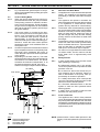
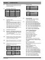
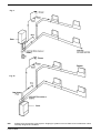
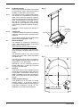
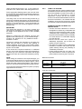
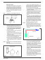
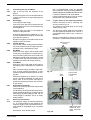
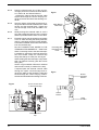
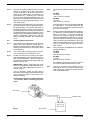
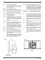
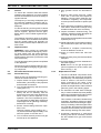
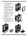
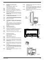
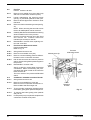
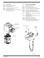
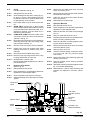
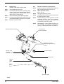
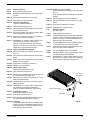
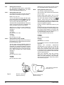
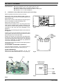
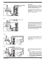
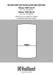
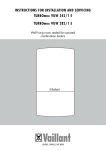
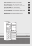
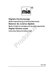
FITTING THE STANDARD (2359029) HORIZONTAL
FLUE KIT (see 5.4.1)
EXTENDING THE HORIZONTAL FLUE
If the horizontal flue requires extension/s or
additional bend/s, the horizontal flue terminal
kit (2359029) must be used. Connect the bend
– supplied with the terminal kit – to the top of the
boiler using the clips, screws, & gaskets
supplied. The additional bends & extensions
have an internal push-fit connection, care should
be taken to ensure that the correct seal is made
when assembling the flue system. Connect the
required number of flue extensions or bends
(up to the maximum equivalent flue length) to
the flue terminal using the clips, screws, &
gaskets supplied (see fig. 13 & 13A).
Carefully measure the distance from the centre of the
appliance flue outlet to the face of the outside wall
(dimension ‘X’ see fig. 13). Ensure the inner (60mm)
pipe is fully inserted into the outer (100mm) pipe (when
the inner pipe is fully inserted, it stands proud of the outer
pipe by 7.5mm). Add 32mm to dimension ‘X’ to give the
overall flue length (dimension ‘Y’). The standard
horizontal flue kit (part no. 2359029) is suitable for a
distance (dimension ‘Y’) of up to 865mm.
IMPORTANT
The flue restrictor ring (see fig. 1) must be
removed or discarded if the total flue length –
including bends – exceeds 1.0m.
NOTE
When cutting the horizontal flue terminal or an
extension to the required length, you must
ensure that the excess is cut from the plain end
of the terminal or extension, and that the inner
(60mm) pipe is 7.5mm longer than outer
(100mm) pipe (see fig. 13 & 13A). Remove any
burrs, and check that any seals are located
properly.
Fig. 13
NOTE
Dimension ‘Y’ is measured from the end of the terminal
to the end of the outer (100mm) pipe.
The internal trim should be fitted to the flue pipe before
connection of the 90º bend.
If the horizontal flue kit (2359029) requires to be cut to
the correct size (dimension ‘Y’), you must ensure that
the inner (60mm) pipe stands proud of the outer (100mm)
pipe by 7.5mm (see fig. 13A). Ensure any burrs are filed
or removed and that any seals are located properly
before assembly.
Connect the inner (60mm) pipe of the terminal assembly
to the push-fit end of the 90º bend (supplied) using a
twisting action. Insert the assembled flue into the
previously drilled hole. Using the clips & screws supplied,
connect the flue assembly to the boiler, ensuring that the
terminal protrudes past the finished outside wall by the
correct length (135mm).
You must ensure that the entire flue system is properly
supported and connected.
Seal the flue assembly to the wall using cement or a
suitable alternative that will provide satisfactory
weatherproofing. The exterior trim can now be fitted.
Fig. 13A
Linea 24 & 28
You must ensure that the entire flue system is
properly supported and connected.
Seal the flue assembly to the wall using cement
or a suitable alternative that will provide
satisfactory weatherproofing. The interior and
exterior trim can now be fitted.
5.5.2
Concentric vertical flue
The vertical flue terminal can be connected
directly to the appliance flue outlet. Alternatively,
an extension or bend can be connected to the
appliance flue outlet if desired (see 5.4.2),
however if additional bends are fitted, a reduction
must be made to the maximum flue length (see
table below).
Reduction for bends
Bend
45º bend
90º bend
Reduction in maximum flue length for
each bend
0.5 metre
1.0 metre
Vertical flue terminal and accessories
Part No.
Description
Length
2359039
Vertical flue terminal
1.0 metre
0225770
Pitched roof flashing
plate
N/A
0225765
Flat roof flashing plate
N/A
2359069
750mm extension
750mm
2359079
1500mm extension
1500mm
2359049
45º bend (pair)
N/A
2359059
90º bend
N/A
0225760
Wall bracket (5)
N/A
11