1
CONTENTS
Section
Subject
Section 1
Page no
Introduction
General Layout
1
1
Design Principles & Operating
Principles
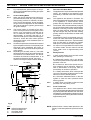
Schematic Diagram
Central Heating Mode
Domestic Hot Water Mode
Safety Devices
Frost Thermosat
2
2
2
2
2
2
Section 3
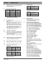
Technical Data
Dimensions & Contents
Connection Sizes
Installation Requirements
Electrical Details
Performance & Limitations
Working Pressure (H/W & C/H)
Flow Rates
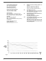
Central Heating Pump Duty
3
3
3
3
3
3
4
4
4
Section 4
General Requirements
Related Documents
Location of Appliance
Gas Supply
Flue System
Air Supply
Water Circulation (C/H)
Pipework
By-Pass
System Design
Filling Point
Electrical Supply
Showers
5
5
5
5
5
6
6
6
6
6
8
8
8
Section 5
Installation
Delivery
Unpacking
Preparing For Mounting
Mounting The Appliance
Fitting The Flue (Horizontal)
Fitting The Flue (Vertical)
Fitting The Flue (Twin)
Connecting Gas & Water Supplies
Electrical connections
9
9
9
9
10
10
11
12
15
15
Commissioning
Gas Installation
Initial Flushing of Pipework
Initial Filling of System
System Design Pressure
Checking Electrical supply
Lighting The Boiler
Checking Burner Pressures
Range Rating C/H
Checking The Flue System
Checking The Heating Thermistor
Regulating The C/H System
Final Flushing The C/H System
Filling & Testing H/W System
Final Checks For Operation
17
17
17
17
17
17
17
18
19
19
19
19
19
19
20
Section 2
Section
Subject
Concluding Operations
Section 7
Instructing The User
20
Section 8
Servicing Instructions
General
Recommended Routine Servicing
Replacement Of Parts
To Gain General Access
To Remove:
Room Sealed Chamber Front Cover
Main Burner & Electrode
Main Burner Injectors
Main Heat Exchanger
Fan
DAPS
Combustion Chamber Insulation Panel
Ignition PCB
Gas Control Valve
Pump
Domestic Flow Switch
Diverter Valve
Domestic Heat Exchanger
Diverter Valve
Main Expansion Vessel
Safety Valve
Pressure Switch
Motorised Valve
Printed Circuit Board
Display Printed Circuit Board
Safety Thermostat
Thermistor Sensors
Pressure Gauge
Setting Gas Pressures
21
21
21
21
22
Section 9
Section 6
Linea 24 & 28
Operational Checks & Wiring
Sequence of Functions
Diagnostic Error Codes
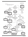
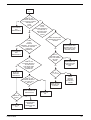
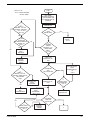
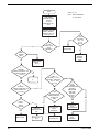
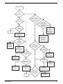
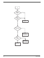
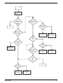
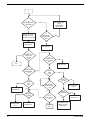
Fault Finding Guides
Page no
20
22
23
23
23
24
24
24
25
25
26
26
26
27
27
27
28
28
29
29
29
29
29
29
30
32
32
33
34-43
Section 10 Appendix
44
Internal Time Clock Installation
44
External Time Clock Installation
46
S & Y Plan Installations
47
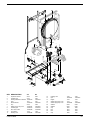
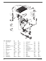
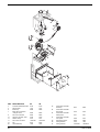
Exploded Diagrams
48-52
Abling & Disabling Controls
53
Functional Flow Diagram
54
Illustrated Wiring Diagram
55
Preliminary Electrical System Checks 56
LPG Instructions
57-58