1
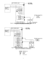
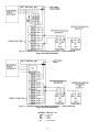
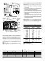
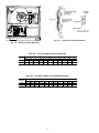
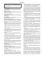
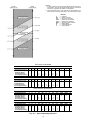
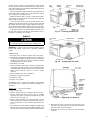
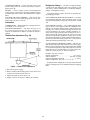
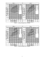
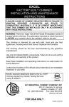
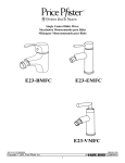
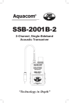
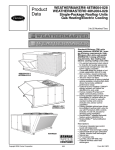
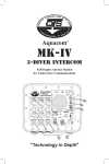
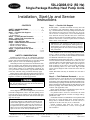
50LJQ008,012 (50 Hz)
Single-Package Rooftop Heat Pump Units
Installation, Start-Up and Service
Instructions
CONTENTS
Step 1 — Provide Unit Support
Page
SAFETY CONSIDERATIONS . . . . . . . . . . . . . . . . . . 1
INSTALLATION . . . . . . . . . . . . . . . . . . . . . . . . . . . . 1-16
Step 1 — Provide Unit Support . . . . . . . . . . . . . . 1
• ROOF CURB
• SLAB MOUNT
Step 2 — Field Fabricate Ductwork . . . . . . . . . . . 1
Step 3 — Make Field Connection for
Condensate Disposal . . . . . . . . . . . . . . . . . . . . . . . . . 3
Step 4 — Rig and Place Unit . . . . . . . . . . . . . . . . . 3
Step 5 — Make Electrical Connections . . . . . . . 7
• FIELD POWER SUPPLY
• FIELD CONTROL WIRING
• HEAT ANTICIPATOR SETTINGS
Step 6 — Adjust Indoor-Fan Speed . . . . . . . . . . . 13
START-UP . . . . . . . . . . . . . . . . . . . . . . . . . . . . . . . . 17-19
SERVICE . . . . . . . . . . . . . . . . . . . . . . . . . . . . . . . . . . 19-21
SAFETY CONSIDERATIONS
Installation and servicing of air conditioning equipment
can be hazardous due to system pressure and electrical components. Only trained and qualified service personnel should
install, repair or service air conditioning equipment.
Untrained personnel can perform basic maintenance functions of cleaning coils and filters and replacing filters. All
other operations should be performed by trained service personnel. When working on air conditioning equipment, observe precautions in the literature, tags and labels attached
to the unit, and other safety precautions that may apply.
Follow all safety codes. Wear safety glasses and work gloves.
Use quenching cloth for unbrazing operations. Have fire extinguisher available for all brazing operations.
Before performing service or maintenance operations on
unit, turn off main power switch to unit. Electrical shock
could cause personal injury.
INSTALLATION
Unit is shipped in the vertical configuration. To convert to
horizontal configuration, remove side duct opening covers.
Using the same screws, install covers on vertical duct openings with the insulation-side down. Seals around duct openings must be tight.
IMPORTANT: An external filter kit MUST be used,
or the filters MUST be field-installed outside the unit
on horizontal applications with accessory economizer
or two-position damper. Otherwise, the economizer or
two-position must be partially removed to access the
filters. The area of the field-installed filters should be
equal to the area of the factory-installed filters.
ROOF CURB — Assemble and install accessory roof curb
in accordance with instructions shipped with curb. See
Fig. 1. Install insulation, cant strips, roofing and counter flashing as shown. Ductwork must be attached to curb, not to the
unit. If electric or control power is to be routed through the
curb, attach the accessory thru-the-curb service connection
plates to the roof curb in accordance with the accessory installation instructions. Connection plates must be installed
before unit is set in roof curb.
IMPORTANT: The gasketing of the unit to the roof
curb is critical for a watertight seal. Install gasket supplied with the roof curb as shown in Fig. 1. Improperly applied gasket also can result in air leaks and poor
unit performance.
Curb should be level. Unit leveling tolerances are shown
in Fig. 2. This is necessary for unit drain to function properly. Refer to Accessory Roof Curb Installation Instructions
for additional information as required.
SLAB MOUNT (Horizontal Units Only) — Provide a level
concrete slab that extends a minimum of 152 mm (6 in.) beyond unit cabinet. The slab should be 203 mm (8 in.) thick
with 102 mm (4 in.) above grade. Install a gravel apron in
front of outdoor coil air inlet to prevent grass and foliage
from obstructing airflow. In areas where high snowfall
occurs, increase height of slab to ensure that snow does not
block coil.
NOTE: Horizontal units may be installed on a roof curb if
required.
Step 2 — Field Fabricate Ductwork — On vertical discharge units, secure all ducts to roof curb and building
structure. Do not connect ductwork to unit. For horizontal
applications, field-supplied flanges should be attached to horizontal discharge openings and all ductwork attached to the
flanges. Insulate and weatherproof all external ductwork, joints
and roof openings with counter flashing and mastic in accordance with applicable codes.
Ducts passing through an unconditioned space must be
insulated and covered with a vapor barrier.
If a plenum return is used on a vertical unit, the return
should be ducted through the roof deck to comply with applicable fire codes.
A minimum clearance to combustibles is not required around
ductwork on vertical discharge units. On horizontal discharge units, a minimum clearance of 25 mm (one in.) is
required for the first 305 mm (12 in.) of ductwork.
Cabinet return-air static shall not exceed −87 Pa
(−.35 in. wg) with economizer or −112 Pa (−.45 in. wg) without economizer.
Manufacturer reserves the right to discontinue, or change at any time, specifications or designs without notice and without incurring obligations.
Catalog No. 015-015
Printed in U.S.A.
Form 50LJQ-C1SI
Pg 1
1-92
Replaces: New
ROOF CURB
ACCESSORY
‘‘A’’
50DJ901371
18-29
[356]
50LJQ008,012
28-09
[610]
50DJ901381
UNIT SIZE
UNIT SIZE
‘‘F’’ POWER
50LJQ008,012
19 [25] NPT or
29 [51] NPT
‘‘G’’ CONTROL
CONNECTOR
PKG. ACC.
⁄ 9 [19] NPT
50DJ901311
34
NOTES:
1. Roof curb accessory is shipped unassembled.
2. Insulated panels: 25 mm (one in.) thick polyurethane foam, .8 Kg (13⁄4 lb) density.
3. Dimensions in [ ] are in millimeters.
4. Roof curb: 16-gage steel.
5. Attach ductwork to curb (flanges of duct rest on curb).
6. Service clearance 1219 mm (4 ft) on each side.
7.
Direction of airflow.
8. Control and power service plates are part of a separately shipped accessory package.
Fig. 1 — Roof Curb Dimensions
2
All panels must be in place when rigging.
POSITIONING — Maintain clearance around and above unit
to provide proper air flow and service access. See Fig. 5.
Position unit on roof curb so that the following clearances
are maintained; 6 mm (1⁄4 in.) clearance between roof curb
and base rails on each side and front of unit: 29 mm (15⁄32
in.) clearance between roof curb and rear of unit (see Fig. 1,
section C-C).
Do not install unit in an indoor location. Do not locate
unit air inlet near exhaust vents or other sources of contaminated air.
Although unit is weatherproof, guard against water from
higher level runoff and overhangs.
After unit is in position, remove polyethylene shipping wrapper and rigging skid.
MAXIMUM ALLOWABLE DIFFERENCE
A-B
mm in.
13
.5
B-C
mm
in.
25
1.0
A-C
mm
in.
25
1.0
Fig. 2 — Unit Leveling Tolerance
Step 3 — Make Field Connection for Condensate Disposal — Units must have an external trap added.
See Fig. 3. A 3⁄4-in. FPT connection is located on the side of
the unit. Use a trap at least 100 mm (4 in.) deep, and protect
against freeze-up.
If drain line is run to a drain, pitch line away from unit at
25 mm (one in.) per 3 m (10 ft) of run. Do not use a pipe size
smaller than the unit connection.
Step 4 — Rig and Place Unit — Inspect unit for transportation damage. File any claim with transportation agency.
Keep unit upright and do not drop. Spreader bars are not
required if top crating is left on unit. Rollers may be used to
move unit across a roof. Level by using unit frame as a reference. See Tables 1A and 1B and Fig. 4 for additional information. Operating weight is shown in Tables 1A and 1B
and Fig. 4.
Lifting holes are provided in base rails as shown in
Fig. 4 and 5. Refer to rigging instructions on unit.
NOTE: Trap should be deep enough to offset maximum unit static
difference. A 100 mm (4 in.) trap is recommended.
Fig. 3 — External Trap Condensate Drain
NOTES:
1. Dimensions in ( ) is in millimeters.
2. Hood rigging shackles through holes in base rail, as shown in
detail ‘‘A’’. Holes in base rails are centered around the unit center
of gravity. Use wooden top skid when rigging to prevent rigging
straps from damaging unit.
3. Weights do not include economizer. See Tables 1A and 1B for economizer weights.
DIMENSIONS
MAX
UNIT WEIGHT
‘‘A’’
‘‘B’’
‘‘C’’
50LJQ
lb kg
in.
mm
in.
mm
in.
mm
008 840 381 87.38 2219 40.25 1022 41.31 1050
012 940 426 87.38 2219 40.25 1022 48.31 1253
All panels must be in place when rigging.
Fig. 4 — Rigging Details
3
Table 1A — Physical Data (SI)
BASE UNIT 50LJQ
NOMINAL CAPACITY (kW)
OPERATING WEIGHT (kg)
Unit
With Economizer
Roof Curb
COMPRESSOR
Quantity
Oil (ml) (each compressor)
REFRIGERANT TYPE
Operating Charge (kg)
Circuit 1
Circuit 2
OUTDOOR FAN
Quantity...Diameter (mm)
Nominal L/s
Motor BkW...r/s
OUTDOOR COIL
Rows...Fins/m
Total Face Area (sq m)
INDOOR FAN
Size (mm)
Type Drive
Nominal L/s
Motor BkW per NEC*
Maximum Continuous BkW
Motor Frame
Fan r/s Range
Motor Bearing Type
Maximum Fan r/s
Motor Pulley Pitch Diameter
A/B (mm)
Fan Pulley Pitch Diameter (mm)
Belt — Type...Length (mm)
Pulley Center Line Distance (mm)
Fan Shaft Diameter at Pulley (mm)
Speed Change per Full Turn of
Movable Pulley Flange (r/s)
Movable Pulley Maximum Full
Turns from Closed Position
Factory Setting — Full Turns Open
Factory Speed Setting (r/s)
INDOOR COIL
Rows...Fins/m
Total Face Area (sq m)
OUTDOOR-AIR INLET SCREENS
Quantity...Size (mm)
RETURN-AIR FILTERS
Quantity...Size (mm)
008
23.2
012
28.8
381
401
101
426
446
101
Hermetic
2
1627
2
2071
R-22
3.7
3.2
4.0
3.9
Propeller
1...660
1...660
2900
3260
.25...16.0
.25...16.0
Enhanced Copper Tubes, Aluminum Fins, Acutrol™ Feed Device
2...669
2...669
1.9
2.3
Centrifugal
381 x 381
381 x 381
Belt
Belt
1200
1600
1.12
1.50
1.79
2.16
56
56
10.30-14.70
11.50-15.00
Ball
Ball
26.7
26.7
61/86
86/112
140
178
A...1219
A...1295
425-489
464-527
25
25
.88
.70
5
5
5
5
10.3
11.5
Enhanced Copper Tubes, Aluminum Double Wavy Fins,
Acutrol Feed Device
3...590
3...590
.74
.93
Cleanable
1...508 x 635 x 25
1...406 x 635 x 25
Disposable
4...406 x 508 x 50
4...508 x 508 x 50
LEGEND
BkW — Brake Kilowatt
NEC — National Electrical Code (U.S.A. Standard)
*Used to determine wire sizing per NEC.
4
Table 1B — Physical Data (English)
BASE UNIT 50QJ
NOMINAL CAPACITY (tons)
OPERATING WEIGHT (lb)
Unit
With Economizer
Roof Curb
COMPRESSOR
Quantity
Oil (fluid oz) (each compressor)
REFRIGERANT TYPE
Operating Charge (lb-oz)
Circuit 1
Circuit 2
OUTDOOR FAN
Quantity...Diameter (in.)
Nominal Cfm
Motor Hp...Rpm
OUTDOOR COIL
Rows...Fins/in.
Total Face Area (sq ft)
INDOOR FAN
Size (in.)
Type Drive
Nominal Cfm
Horsepower per NEC*
Maximum Continuous Bhp
Motor Frame
Fan Rpm Range
Motor Bearing Type
Maximum Fan Rpm
Motor Pulley Pitch Diameter
A/B (in.)
Fan Pulley Pitch Diameter (in.)
Belt — Type...Length (in.)
Pulley Center Line Distance (in.)
Fan Shaft Diameter at Pulley (in.)
Speed Change per Full Turn of
Movable Pulley Flange (rpm)
Movable Pulley Maximum Full
Turns from Closed Position
Factory Setting — Full Turns Open
Factory Speed Setting (Rpm)
INDOOR COIL
Rows...Fins/in.
Total Face Area (sq ft)
OUTDOOR-AIR INLET SCREENS
Quantity...Size (in.)
RETURN-AIR FILTERS
Quantity...Size (in.)
008
6.6
012
8.2
840
884
223
940
984
223
Hermetic
2
55
2
70
R-22
8-2
7-0
8-14
8-10
Propeller
1...26
1...26
6100
6900
1⁄3...960
1⁄3...960
Enhanced Copper Tubes, Aluminum Fins, Acutrol™ Feed Device
2...17
2...17
20.5
25.0
Centrifugal
15 x 15
15 x 15
Belt
Belt
2600
3400
1.5
2.0
2.4
2.9
56
56
622-882
692-896
Ball
Ball
1600
1600
2.4/3.4
3.4/4.4
5.5
7.0
A...48
A...51
16.75-19.25
18.25-20.75
1
1
52
42
5
5
5
5
620
690
Enhanced Copper Tubes, Aluminum Double Wavy Fins,
Acutrol Feed Device
3...15
3...15
8.0
10.0
Cleanable
1...20 x 25 x 1
1...16 x 25 x 1
Disposable
4...16 x 20 x 2
4...20 x 20 x 2
LEGEND
Bhp — Brake Horsepower
NEC — National Electrical Code (U.S.A. Standard)
*Used to determine wire sizing per NEC.
5
UNIT
50LJQ
008
012
STD. UNIT ECONOMIZER
CORNER
CORNER
CORNER
CORNER
‘‘H’’
‘‘J’’
‘‘K’’
WEIGHT
WEIGHT
WEIGHT ‘‘A’’ WEIGHT ‘‘B’’ WEIGHT ‘‘C’’ WEIGHT ‘‘D’’
Lb
Kg
Lb
Kg
Lb
Kg
Lb
Kg
Lb
Kg
Lb
Kg
Ft-in. mm Ft-in. mm Ft-in. mm
840 381
44
20
182
83
156
71
231
105
271
123 2-07⁄8 632 3-55⁄16 1050 2-911⁄16 856
940 426
44
20
204
93
174
79
259
117
303
137 1-27⁄8 378 4-15⁄16 1253 3-03⁄8
924
NOTES:
1. Dimensions in [
2.
3.
] are in millimeters.
Center of gravity.
Direction of airflow.
4. Ductwork to be attached to accessory roof curb only.
5. Minimum clearance (local codes or jurisdiction may prevail):
a. Bottom to combustible surfaces (when not using curb) 25 mm
(one in.).
b. Condenser coil, for proper airflow, 914 mm (36 in.) one side,
305 mm (12 in.) the other. The side getting the greater clearance is optional.
c. Overhead 1524 mm (60 in.) to assure proper outdoor fan
operation.
d. Between units, control box side, 1067 mm (42 in.).
e. Between unit and ungrounded surfaces, control box side, 914
mm (36 in.).
f. Between unit and block or concrete walls and other grounded
surfaces, control box side 1067 mm (42 in.).
g. Horizontal supply and return end, zero mm (zero in.).
6. With the exception of the clearance for the outdoor coil as stated
in notes 5b and c, a removable fence or barricade requires no
clearance.
A
B
C
D
E
F
CONNECTION SIZES
13⁄89 dia [35] field power supply hole
21⁄29 dia [64] power supply knockout
13⁄49 dia [44] charging-port hole
7⁄89 dia [22] field control wiring hole
3⁄49-14 NPT condensate drain
29 dia [51] power supply knockout
Fig. 5 — Base Unit Dimensions
6
Step 5 — Make Electrical Connections
Unit cabinet must have uninterrupted, unbroken electrical ground to minimize the possibility of personal
injury if an electrical fault should occur. This ground
may consist of electrical wire connected to unit ground
lug in control compartment, or conduit approved for electrical ground when installed in accordance with U.S.A.
National Electrical Code (Ref: ANSI/NFPA 70-1987)
or equivalent local electrical codes. Failure to follow this
warning could result in the installer being liable for personal injury of others.
FIELD POWER SUPPLY — Pigtails are provided for field
wire connections. Use factory-supplied splices or copper/
aluminum connector.
When installing units, provide a disconnect per local codes.
All field wiring must comply with local requirements.
Install conduit through side panel openings. For units without electric heat, install conduit between disconnect and control box. Install power lines to terminal connections as shown
in Fig. 6. For units with electric resistance heat, refer to Table
2 to determine appropriate power wiring figure (Fig.7-13)
and route lines as indicated in appropriate figure.
Voltage to compressor terminals during operation must be
within voltage range indicated on unit nameplate (also see
Table 2). On 3-phase units, voltages between phases must be
balanced within 2% and the current within 10%. Use the formula shown in Table 2, Note 3 to determine the % voltage
imbalance. Operation on improper line voltage or excessive
phase imbalance constitutes abuse and may cause damage to
electrical components. Such operation would invalidate any
applicable Carrier warranty.
When electric heat is installed, remove knockouts for appropriate size conduit from unit block-off panel and single
point box. Install conduit (rigid or electro-metallic tubing)
through conduit drip boot as shown in Fig. 14. Drip boot
eliminates the need for water tight conduit fittings at the single
point box. Refer to Fig. 15 for component locations.
LEGEND
C
— Contactor
IFC — Indoor-Fan Contactor
TB — Terminal Block
Field Wiring
Factory Wiring
Splice Connection (Factory Supplied)
Fig. 6 — Power Wiring Connections
LEGEND FOR FIG. 7-13
EQUIP
FU
GND
HTR
TB
—
—
—
—
—
Equipment
Fuse
Ground
Heater
Terminal Block
Fig. 7 — Electric Heater Power Wiring Connections — 50LJQ, 220-3-50 and 400-3-50;
Single Point Kit 50DJ902021 and 50DJ902071
7
Fig. 8 — Electric Heater Power Wiring Connections — 50LJQ, 400-3-50;
Single Point Kit 50DJ902041 and 50DJ902101
Fig. 9 — Electric Heater Power Wiring Connections — 50LJQ, 400-3-50;
Single Point Kit 50DJ902061 and 50DJ902121
8
Fig. 10 — Electric Heater Power Wiring Connections — 50LJQ, 220-3-50;
Single Point Kit 50DJ902031 and 50DJ902081
Fig. 11 — Electric Heater Wiring Connections — 50LJQ, 220-3-50;
Single Point Kit 50DJ902051 and 50DJ902111
LEGEND FOR FIG. 7-13
EQUIP
FU
GND
HTR
TB
—
—
—
—
—
Equipment
Fuse
Ground
Heater
Terminal Block
9
Fig. 12 — Electric Heater Power Wiring Connections — 50LJQ, 220-3-50;
Single Point Kit 50DJ902091
Fig. 13 — Electric Heater Power Wiring Connections — 50LJQ, 220-3-50;
Single Point Kit 50DJ902131
LEGEND FOR FIG. 7-13
EQUIP
FU
GND
HTR
TB
—
—
—
—
—
Equipment
Fuse
Ground
Heater
Terminal Block
10
Table 2 — Electrical Data
UNIT NOMINAL
50LJQ V-PH-HZ
VOLTAGE
RANGE
COMPR
(each)
Min Max RLA
LRA
OFM
IFM
ELECTRIC HEAT POWER SUPPLY ELECTRIC HEAT ELECTRIC HEAT
POWER WIRING
PART NO.
FIG. NO.
50DJ901—
FLA Hp FLA Nominal
FLA
MCA
MOCP†
kW*
220-3-50
198
242
15.3
82.0
1.5
1.5
5.8
400-3-50
360
440
7.7
41.0
1.5
1.5
2.6
220-3-50
198
242
19.6 105.0
1.5
2.0
7.5
400-3-50
360
440
10.4
1.5
2.0
3.5
008
012
55.0
—
9.5
14.6
22.7
29.3
38.8
10.5
12.5
21.0
25.0
31.5
—
9.5
14.6
29.3
43.9
10.5
12.5
21.0
25.0
31.5
37.5
—
—
—
—
—
—
—
—
—
Compressor
Full Load Amps
Heating, Air Conditioning and Refrigeration
Indoor-Fan Motor
Locked Rotor Amps
Minimum Circuit Amps
Maximum Overcurrent Protection
Outdoor-Fan Motor
Rated Load Amps
50
80
90
150
175
200
25
45
60
70
80
60
90
100
150
200
35
60
70
80
90
100
—
10
10
11
11
12
7
7
8
8
9
—
10
10
11
13
7
7
8
8
9
9
Average Voltage =
=
—
711
601
611
621
711, 621**
681
631
641
651
681, 641**
—
711
601
621
601, 621**
681
631
641
651
681, 641**
631, 651**
393 + 403 + 396
3
1192
= 397
3
Determine maximum deviation from average voltage.
(AB) 397 − 393 = 4 v
(BC) 403 − 397 = 6 v
(AC) 397 − 396 = 1 v
Maximum deviation is 6 v.
Determine % voltage imbalance.
*Heaters are field-installed only. Heater capacity (kW) is based on
heater voltage of 230 v or 400 v. If power distribution voltage to unit
varies from rated heater voltage, heater kW will vary
accordingly.
†Fuse or HACR circuit breaker.
**Requires 2 heater packages.
NOTES:
1. MCA and MOCP values are calculated in accordance with NEC
(National Electric Code) (U.S.A. Standard), Article 440.
2. Motor RLA and FLA values are established in accordance with UL
(Underwriters’ Laboratories) Standard 465 (U.S.A. Standard).
3. Unbalanced 3-Phase Supply Voltage
Never operate a motor where a phase imbalance in supply voltage is greater than 2%. Use the following formula to determine
the % voltage imbalance.
% Voltage Imbalance
= 100 x
41.7
70.3
85.7
130.0
158.5
179.5
21.4
44.0
59.3
66.5
78.3
53.1
81.6
97.1
141.3
190.9
28.4
51.0
66.3
73.5
85.2
96.6
Example: Supply voltage is 400-3-50.
AB = 393 v
BC = 403 v
AC = 396 v
LEGEND
COMPR
FLA
HACR
IFM
LRA
MCA
MOCP
OFM
RLA
—
24.7
38.0
59.0
76.2
100.9
15.2
18.0
30.3
36.1
45.5
—
24.7
38.0
76.2
114.1
15.2
18.0
30.3
36.1
45.5
54.2
6
= 1.5%
397
This amount of phase imbalance is satisfactory as it is below the
maximum allowable 2%.
% Voltage Imbalance = 100 x
IMPORTANT: If the supply voltage phase imbalance is
more than 2%, contact your local electric utility company
immediately.
max voltage deviation from average voltage
average voltage
11
15 to 23 m (51 to 75 ft), use no. 16 AWG insulated
wire (35 C minimum). For over 23 m (75 ft), use no. 14
AWG insulated wire (35 C minimum). See Table 3 for wire
conversions.
1. If unit is mounted on roof curb and accessory thru-thecurb service plate connection is used, route wire through
connection plate.
2. Pass control wires through the hole provided on unit (see
connection D, Connection Sizes table, Fig. 5).
3. Feed wire through the raceway built into the corner post
to the 24-v barrier located on the left side of the control
box. See Fig. 17. The raceway provides the UL (U.S.A.
Standard) required clearance between high- and lowvoltage wiring.
4. Connect thermostat wires to screw terminals of lowvoltage connector. The connector plugs into the control
board and may be removed to make connection. Plug connector back into the control board after making connection or unit will not operate.
Fig. 14 — Conduit Installation
DISCONNECT
MOUNTING
LOCATION
EMT OR RIGID
CONDUIT
(FIELDMAIN
SUPPLIED) CONTROL
BOX
BRACKET AND
CONDUIT DRIP
BOOT
MANUAL RESET
LIMIT SWITCH
LOCATION
(HIDDEN)
HEAT ANTICIPATOR SETTINGS — Set first-stage heat anticipator settings at 1.0. Set second-stage heat anticipator settings at 0.6. For units with optional electric heat,
set anticipator for second stage as shown in Table 4.
CENTER POST
HEATER
COVERS
Table 3 — American/European Wire Conversions
HEATER
WIRING
LABEL
AMERICAN
Industry
Standard Size
HEATER
MOUNTING
BRACKET
SINGLE
POINT
BOX
SINGLE POINT
BOX MOUNTING
SCREWS
CONTROL WIRE
TERMINAL
BLOCK
HEATER
MODULE
(LOCATION 1)
18 AWG
16 AWG
14 AWG
12 AWG
10 AWG
8 AWG
6 AWG
4 AWG
3 AWG
2 AWG
1 AWG
1/0 AWG
2/0 AWG
3/0 AWG
4/0 AWG
250 kcmil
300 kcmil
350 kcmil
400 kcmil
500 kcmil
600 kcmil
HEATER
MODULE
(LOCATION 2)
Fig. 15 — Component Location
FIELD CONTROL WIRING — Install a Carrier-approved
accessory thermostat assembly according to installation instructions included with the accessory. Locate thermostat assembly on a solid wall in the conditioned space to sense average temperature in accordance with thermostat installation
instructions.
Route thermostat cable or equivalent single leads of colored wire from subbase terminals to low-voltage connections on unit (shown in Fig. 16) as described in Steps 1-4
below.
NOTE: For wire runs up to 15 m (50 ft), use no. 18 AWG
(American Wire Gage) insulated wire (35 C minimum). For
American
Conversion
(mm2)
0.82
1.30
2.08
3.30
5.25
6.36
13.29
21.14
26.65
33.61
42.39
53.49
67.42
85.00
107.19
126.64
151.97
177.90
202.63
253.29
303.95
EUROPEAN
Industry
Standard
Size (mm2)
1.0
1.5
2.5
4.0
6.0
10.0
16.0
25.0
—
35.0
50.0
—
70.0
95.0
120.0
150.0
—
185.0
240.0
300.0
—
LEGEND
AWG — American Wire Gage
kcmil — Thousand Circular Mils
Table 4 — Unit Voltage
Heater kW
9.5
14.6
22.7
29.3
38.8
43.9
220
Anticipator Setting
0.3
0.3
0.6
0.6
0.9
0.9
Part No. 50DJ901—
711
601
611
621
711, 621*
711, 621*
Heater kW
10.5
12.5
21.0
25.0
31.5
37.5
*Requires 2 heater packages.
12
400
Anticipator Setting
0.3
0.3
0.3
0.3
0.6
0.6
Part No. 50DJ901—
681
631
641
651
681, 641*
631, 651*
LEGEND
BAT
C
CB
DAT
EMC/EMFC
EMO/EMFO
EQUIP
GND
HR
IFC
—
—
—
—
—
—
—
—
—
—
Battery
Contactor
Circuit Breaker
Discharge-Air Thermistor
Energy Management Closed
Energy Management Open
Equipment
Ground
Heater Relay
Indoor-Fan Contactor
OFC
P
TB
TRAN
—
—
—
—
Outdoor-Fan Contactor
Plug
Terminal Board
Transformer
Field Wiring
Factory Wiring
Splice Connection (Factory Supplied)
Fig. 16 — Field Wiring Connections
Tables 5A and 5B show fan rps and rpm at motor pulley
settings. Refer to Tables 6-13 to determine fan speed
settings.
Fan motor pulleys are factory set for speed shown in
Tables 1A and 1B.
UNIT
CONTROL
BOARD
To change fan speed:
a. Shut off unit power supply.
b. Loosen belt by loosening fan motor mounting nuts. See
Fig. 18.
c. Loosen movable pulley flange setscrew (see Fig. 19).
d. Screw movable flange toward fixed flange to increase speed
and away from fixed flange to decrease speed. Increasing
fan speed increases load on motor. Do not exceed maximum speed specified in Tables 1A and 1B.
e. Set movable flange at nearest keyway of pulley hub and
tighten setscrew (see Tables 1A and 1B for speed change
for each full turn of pulley flange).
RACEWAY
Fig. 17 — Field Control Wiring Raceway
Step 6 — Adjust Indoor-Fan Speed — Adjust indoor fan speed to meet jobsite conditions.
For units with electric resistance heating, required minimum L/s (cfm) is 1062 (2250) for 50LJQ008 and 1416 (3000)
or 50LJQ012, with the following exceptions.
UNIT
50LJQ
UNIT
VOLTAGE
HEATER
kW
220
50.0
400
50.0
012
UNIT
CONFIGURATION
Horizontal
or Vertical
Horizontal
or Vertical
To align fan and motor pulleys:
a. Loosen fan pulley setscrews.
b. Slide fan pulley along fan shaft.
c. Make angular alignment by loosening motor from mounting plate.
REQUIRED
MINIMUM
L/s
Cfm
1534
3250
1605
3400
To adjust belt tension (see Fig. 18):
a. Loosen fan motor mounting bolts.
b. Slide motor mounting plate away from fan scroll for proper
belt tension (13 mm [1⁄2-in.] deflection with one finger)
and tighten mounting bolts.
c. Adjust bolt and nut on motor mounting plate to secure
motor in fixed position.
13
MOTOR MOUNTING
NUTS AND BOLTS
Fig. 19 — Indoor-Fan Pulley Adjustment
Fig. 18 — Belt-Drive Motor Mounting
Table 5A — Fan R/s at Motor Pulley Settings (SI)
50LJQ
008
012
0
14.70
15.00
⁄
14.26
14.65
12
1
13.82
14.30
MOTOR PULLEY TURNS OPEN
11⁄2
2
21⁄2
3
31⁄2
13.38 12.94 12.50 12.06 11.62
13.95 13.60 13.25 12.90 12.55
4
11.18
12.20
41⁄2
10.74
11.85
5
10.30
11.50
Table 5B — Fan Rpm at Motor Pulley Settings (English)
50LJQ
008
012
0
882
896
⁄
856
875
12
1
830
855
MOTOR PULLEY TURNS OPEN
⁄
2
21⁄2
3
3 1 ⁄2
804
778
752
726
700
834
814
794
774
753
12
14
4
674
733
41⁄2
648
712
5
622
692
Table 6 — Fan Performance (SI), 50LJQ008 (50 Hz) — Horizontal Discharge Units
AIRFLOW
(L/s)
1100
1200
1300
1400
1500
1600
1700
50
r/s BkW
7.9 0.35
8.3 0.42
8.8 0.51
9.2 0.60
9.7 0.71
10.1 0.82
10.6 0.93
100
r/s BkW
9.4 0.50
9.8 0.59
10.2 0.69
10.6 0.80
11.0 0.91
11.3 1.04
11.8 1.20
150
r/s BkW
10.6 0.68
11.0 0.78
11.3 0.88
11.7 0.99
12.1 1.12
12.5 1.28
12.9 1.44
EXTERNAL STATIC PRESSURE (Pa)
200
250
300
350
r/s BkW r/s BkW r/s BkW r/s BkW
11.7 0.85 12.7 1.03 13.6 1.25 14.4 1.46
12.0 0.95 13.0 1.15 13.9 1.36 14.8 1.58
12.4 1.08 13.3 1.28 14.2 1.49 15.0 1.72
12.7 1.22 13.7 1.42 14.5 1.63 15.3 1.87
13.0 1.35 14.0 1.59 14.8 1.81 15.6 2.04
13.4 1.49 14.3 1.75 15.2 2.00 15.9 2.24
13.8 1.67 14.7 1.92 15.5 2.20 —
—
400
r/s BkW
14.9 1.69
15.5 1.82
15.8 1.96
16.1 2.12
16.4 2.30
—
—
—
—
450
500
r/s BkW r/s BkW
15.1 1.92 15.0 2.15
16.0 2.06 16.4 2.31
16.5 2.21 17.1 2.47
16.9 2.38 —
—
—
—
—
—
—
—
—
—
—
—
—
—
Table 7 — Fan Performance (SI), 50LJQ012 (50 Hz) — Horizontal Discharge Units
AIRFLOW
(L/s)
1300
1400
1500
1600
1700
1800
1900
2000
2100
2200
2300
50
r/s BkW
7.6 0.30
8.0 0.40
8.4 0.48
8.8 0.58
9.1 0.69
9.5 0.81
9.9 0.95
10.3 1.11
10.7 1.29
11.2 1.48
11.6 1.70
100
r/s BkW
8.9 0.41
9.3 0.51
9.6 0.60
10.0 0.69
10.3 0.78
10.7 0.90
11.0 1.02
11.4 1.17
11.8 1.33
12.1 1.51
12.5 1.71
150
r/s BkW
10.2 0.56
10.5 0.64
10.7 0.72
11.1 0.82
11.3 0.93
11.7 1.05
12.0 1.18
12.3 1.32
12.7 1.47
13.1 1.64
13.4 1.83
EXTERNAL STATIC PRESSURE (Pa)
200
250
300
350
r/s BkW r/s BkW r/s BkW r/s BkW
11.1 0.64 12.1 0.77 13.1 0.92 13.9 0.93
11.4 0.75 12.4 0.88 13.3 1.01 14.1 1.11
11.8 0.86 12.7 0.99 13.5 1.12 14.3 1.26
12.1 0.96 12.9 1.10 13.8 1.24 14.5 1.38
12.3 1.07 13.2 1.22 14.0 1.37 14.8 1.52
12.6 1.20 13.5 1.36 14.3 1.52 15.0 1.67
12.9 1.34 13.8 1.50 14.6 1.68 15.3 1.83
13.2 1.48 14.1 1.66 14.9 1.83 15.6 2.01
13.5 1.65 14.4 1.84 15.1 2.00 15.9 2.20
13.9 1.83 14.6 2.01 15.4 2.20 16.2 2.38
14.2 2.01 15.0 2.20 15.7 2.41 —
—
400
r/s BkW
14.0 0.52
14.6 0.96
15.1 1.35
15.3 1.54
15.5 1.66
15.8 1.83
16.0 2.00
16.3 2.18
16.6 2.38
—
—
—
—
450
r/s BkW
15.0 1.13
15.4 1.32
15.7 1.49
16.0 1.64
16.3 1.84
16.4 1.99
16.7 2.16
17.0 2.36
—
—
—
—
—
—
500
r/s BkW
15.6 1.32
16.0 1.42
16.4 1.54
16.7 1.72
17.0 1.95
17.2 2.17
17.3 2.33
17.6 2.53
—
—
—
—
—
—
Table 8 — Fan Performance (SI), 50LJQ008 (50 Hz) — Vertical Discharge Units
AIRFLOW
(L/s)
1100
1200
1300
1400
1500
1600
1700
50
r/s BkW
8.7 0.42
9.3 0.52
9.8 0.64
10.4 0.77
11.0 0.92
11.6 1.08
12.2 1.26
100
r/s BkW
10.1 0.59
10.5 0.69
11.0 0.81
11.5 0.94
12.0 1.10
12.6 1.28
13.1 1.48
150
r/s BkW
11.1 0.75
11.6 0.87
12.1 1.01
12.6 1.16
13.0 1.33
13.5 1.50
14.0 1.70
EXTERNAL STATIC PRESSURE (Pa)
200
250
300
350
r/s BkW r/s BkW r/s BkW r/s BkW
12.2 0.93 13.1 1.12 14.0 1.30 14.8 1.51
12.6 1.05 13.5 1.26 14.3 1.46 15.1 1.66
13.0 1.20 13.9 1.41 14.7 1.63 15.5 1.84
13.5 1.37 14.3 1.58 15.1 1.80 15.9 2.04
13.9 1.56 14.7 1.78 15.5 2.00 16.3 2.25
14.4 1.76 15.2 2.00 16.0 2.23 16.7 2.47
14.9 1.97 15.7 2.23 16.4 2.48 —
—
400
r/s BkW
15.7 1.77
15.9 1.88
16.2 1.98
16.6 2.27
17.0 2.50
—
—
—
—
450
500
r/s BkW r/s BkW
16.4 2.02 17.2 2.35
16.7 2.14 17.4 2.44
16.9 2.29 17.6 2.56
17.3 2.51 —
—
—
—
—
—
—
—
—
—
—
—
—
—
Table 9 — Fan Performance (SI), 50LJQ012 (50 Hz) — Vertical Discharge Units
AIRFLOW
(L/s)
1300
1400
1500
1600
1700
1800
1900
2000
2100
2200
2300
50
r/s BkW
8.4 0.37
8.8 0.46
9.2 0.55
9.7 0.65
10.2 0.75
10.6 0.87
11.1 1.01
11.6 1.16
12.0 1.32
12.5 1.50
13.0 1.70
100
r/s BkW
9.6 0.51
10.0 0.59
10.4 0.68
10.8 0.79
11.2 0.91
11.7 1.05
12.1 1.19
12.5 1.35
13.0 1.53
13.4 1.71
13.9 1.91
150
r/s BkW
10.8 0.61
11.1 0.71
11.5 0.81
11.8 0.93
12.2 1.06
12.6 1.20
13.0 1.35
13.4 1.52
13.8 1.70
14.3 1.91
14.7 2.13
EXTERNAL STATIC PRESSURE (Pa)
200
250
300
350
r/s BkW r/s BkW r/s BkW r/s BkW
11.7 0.69 12.6 0.81 13.3 0.90 14.3 1.05
12.0 0.82 12.9 0.93 13.7 1.04 14.5 1.17
12.4 0.94 13.2 1.06 14.0 1.19 14.8 1.26
12.8 1.07 13.6 1.19 14.4 1.33 15.1 1.46
13.1 1.20 13.9 1.34 14.7 1.48 15.4 1.63
13.5 1.35 14.3 1.51 15.0 1.65 15.7 1.80
13.9 1.52 14.7 1.68 15.4 1.84 16.1 1.99
14.3 1.69 15.0 1.86 15.8 2.04 16.5 2.21
14.6 1.88 15.4 2.07 16.1 2.25 16.8 2.43
15.1 2.09 15.8 2.29 16.5 2.48 —
—
15.5 2.31 16.2 2.52 —
—
—
—
400
r/s BkW
15.1 1.27
15.4 1.35
15.6 1.44
15.8 1.59
16.1 1.76
16.4 1.95
16.8 2.14
17.1 2.36
—
—
—
—
—
—
450
r/s BkW
15.9 1.48
16.2 1.56
16.4 1.62
16.5 1.72
16.7 1.89
17.1 2.10
17.4 2.31
17.7 2.53
—
—
—
—
—
—
500
r/s BkW
16.7 1.67
16.8 1.75
17.1 1.83
17.3 1.91
17.4 2.04
17.7 2.24
18.0 2.46
—
—
—
—
—
—
—
—
LEGEND
r/s
— Wheel Speed (Revolutions per Second)
Bkw — Fan Shaft Power (kW)
motor and electrical testing on the Weathermaker I units ensures
that the full power range of the motor can be utilized with confidence. Using the fan motors up to the power ratings shown will
not result in nuisance tripping or premature motor failure. Unit warranty will not be affected.
4. Use of field-supplied motor may affect wire sizing. Contact
Carrier representative to verify.
5. Values include losses for filters, unit casings and wet coils.
6. Motor drive range is 10.30 to 14.70 r/s (622 to 882 rpm) on the
50LJQ008 and 11.50 to 15.00 r/s (692 to 896 rpm) on the 50LJQ012.
All other r/s (rpms) will require a field-supplied drive.
NOTES:
1. Boldface indicates field-supplied drive required.
2.
indicates field-supplied motor and drive required.
3. Maximum usable output power (BkW) on the 50LJQ008 unit is 1.79
(2.40 Bhp) with standard 1.12 BkW (1.5 hp) motor. The maximum
usable output power (BkW) increases to 2.16 (2.90 Bhp) on the
50LJQ012 unit with standard 1.5 BkW (2 hp) motor. Extensive
15
Table 10 — Fan Performance (English), 50LJQ008 (50 Hz) — Horizontal Discharge Units
AIRFLOW
(Cfm)
2200
2400
2600
2800
3000
3200
3400
3600
3800
EXTERNAL STATIC
0.2
0.4
0.6
0.8
1.0
Rpm Bhp Rpm Bhp Rpm Bhp Rpm Bhp Rpm Bhp
459 0.42 549 0.62 625 0.83 691 1.06 753 1.31
482 0.50 569 0.71 645 0.95 708 1.18 768 1.40
507 0.59 592 0.82 663 1.08 727 1.32 784 1.58
533 0.71 615 0.95 683 1.20 747 1.49 802 1.75
559 0.83 637 1.09 704 1.35 765 1.66 823 1.94
585 0.96 660 1.24 727 1.52 785 1.83 841 2.15
610 1.10 682 1.41 750 1.72 806 2.01 860 2.36
636 1.25 707 1.60 772 1.93 828 2.23 880 2.57
661 1.41 733 1.82 795 2.15 852 2.48 901 2.80
PRESSURE (in. wg)
1.2
1.4
1.6
1.8
2.0
Rpm Bhp Rpm Bhp Rpm Bhp Rpm Bhp Rpm Bhp
805 1.58 842 1.87 857 2.16 851 2.45 823 2.70
824 1.72 872 2.01 909 2.32 931 2.64 935 2.96
839 1.87 891 2.17 936 2.49 973 2.82 999 3.16
855 2.04 906 2.35 954 2.67 997 3.01 1034 3.36
872 2.22 921 2.54 969 2.88 1014 3.22 —
—
892 2.45 939 2.76 984 3.10 —
—
—
—
912 2.69 958 3.01 1002 3.34 —
—
—
—
930 2.95 978 3.29 —
—
—
—
—
—
949 3.20 —
—
—
—
—
—
—
—
Table 11 — Fan Performance (English), 50LJQ012 (50 Hz) — Horizontal Discharge Units
AIRFLOW
(Cfm)
3000
3200
3400
3600
3800
4000
4200
4400
4600
4800
5000
EXTERNAL STATIC
0.2
0.4
0.6
0.8
1.0
Rpm Bhp Rpm Bhp Rpm Bhp Rpm Bhp Rpm Bhp
484 0.55 560 0.70 631 0.87 690 1.03 747 1.20
505 0.66 579 0.81 646 0.98 708 1.16 761 1.34
527 0.78 599 0.93 664 1.11 724 1.30 775 1.48
548 0.92 619 1.05 680 1.24 738 1.43 794 1.64
571 1.08 639 1.19 698 1.39 756 1.60 810 1.81
593 1.25 659 1.35 717 1.56 773 1.78 823 1.98
616 1.45 680 1.53 737 1.74 789 1.95 841 2.18
639 1.67 701 1.73 757 1.92 807 2.16 858 2.41
662 1.91 722 1.95 777 2.13 827 2.38 874 2.62
686 2.17 744 2.20 797 2.36 846 2.62 891 2.85
710 2.45 766 2.47 816 2.61 866 2.86 910 3.12
PRESSURE (in. wg)
1.2
1.4
1.6
1.8
Rpm Bhp Rpm Bhp Rpm Bhp Rpm Bhp
800 1.38 850 1.52 879 1.38 925 1.81
812 1.51 862 1.71 908 1.85 944 2.01
827 1.67 873 1.85 920 2.07 963 2.21
840 1.83 888 2.04 931 2.23 976 2.47
856 2.02 901 2.23 945 2.44 986 2.65
875 2.22 915 2.42 960 2.65 1000 2.87
889 2.41 934 2.65 972 2.87 1015 3.12
903 2.62 951 2.89 990 3.12 1028 3.36
921 2.87 965 3.11 1008 3.39 —
—
938 3.14 980 3.37 —
—
—
—
934 3.39 —
—
—
—
—
—
2.0
Rpm Bhp
964 1.92
984 2.09
1001 2.31
1017 2.62
1029 2.89
1039 3.10
1053 3.34
—
—
—
—
—
—
—
—
Table 12 — Fan Performance (English), 50LJQ008 (50 Hz) — Vertical Discharge Units
AIRFLOW
(Cfm)
2200
2400
2600
2800
3000
3200
3400
3600
3800
EXTERNAL STATIC
0.2
0.4
0.6
0.8
1.0
Rpm Bhp Rpm Bhp Rpm Bhp Rpm Bhp Rpm Bhp
503 0.50 585 0.71 653 0.92 716 1.15 772 1.38
534 0.61 613 0.84 677 1.06 738 1.30 794 1.55
565 0.74 639 0.97 703 1.20 761 1.46 816 1.74
597 0.89 665 1.12 731 1.40 786 1.66 839 1.93
629 1.06 694 1.29 759 1.59 812 1.88 862 2.15
662 1.25 724 1.50 785 1.80 840 2.11 887 2.41
696 1.46 756 1.73 811 2.02 868 2.37 914 2.69
729 1.69 787 1.98 839 2.27 894 2.64 942 2.99
763 1.95 819 2.27 869 2.56 920 2.92 970 3.31
PRESSURE (in. wg)
1.2
1.4
1.6
1.8
Rpm Bhp Rpm Bhp Rpm Bhp Rpm Bhp
824 1.63 884 1.95 934 2.30 916 2.64
844 1.81 892 2.08 944 2.40 987 2.76
866 2.01 913 2.29 957 2.58 1004 2.91
889 2.23 935 2.52 978 2.62 1019 3.13
911 2.46 957 2.78 1000 3.09 1040 3.41
934 2.71 980 3.04 1022 3.38 —
—
959 3.00 1003 3.32 —
—
—
—
984 3.32 —
—
—
—
—
—
—
—
—
—
—
—
—
—
2.0
Rpm Bhp
1019 3.09
1039 3.20
1050 3.31
1061 3.47
—
—
—
—
—
—
—
—
—
—
Table 13 — Fan Performance (English), 50LJQ012 (50 Hz) — Vertical Discharge Units
AIRFLOW
(Cfm)
3000
3200
3400
3600
3800
4000
4200
4400
4600
4800
5000
EXTERNAL STATIC
0.2
0.4
0.6
0.8
1.0
Rpm Bhp Rpm Bhp Rpm Bhp Rpm Bhp Rpm Bhp
532 0.64 605 0.81 670 0.97 725 1.12 778 1.28
557 0.75 628 0.93 690 1.10 746 1.28 796 1.44
583 0.88 651 1.06 711 1.25 767 1.44 815 1.61
609 1.01 674 1.22 732 1.42 787 1.61 836 1.80
535 1.16 698 1.39 755 1.59 808 1.80 857 2.01
662 1.33 722 1.57 778 1.78 829 2.01 878 2.22
689 1.52 746 1.77 801 1.99 851 2.23 898 2.45
715 1.72 772 1.99 825 2.22 873 2.46 919 2.71
742 1.94 797 2.22 848 2.48 896 2.72 940 2.98
770 2.18 823 2.46 872 2.75 919 3.00 963 3.27
797 2.44 849 2.73 897 3.04 943 3.30 —
—
LEGEND
PRESSURE
1.2
Rpm Bhp
825 1.43
844 1.61
863 1.79
880 1.98
901 2.20
922 2.44
943 2.69
963 2.94
984 3.22
—
—
—
—
(in. wg)
1.4
Rpm Bhp
874 1.60
888 1.70
907 1.97
926 2.18
943 2.39
962 2.63
983 2.91
1004 3.19
1025 3.48
—
—
—
—
1.6
Rpm Bhp
926 1.82
934 1.94
947 2.14
966 2.36
985 2.60
1003 2.84
1021 3.11
1042 3.41
—
—
—
—
—
—
1.8
Rpm Bhp
974 2.11
988 2.18
991 2.32
1004 2.54
1023 2.79
1042 3.06
1060 3.34
—
—
—
—
—
—
—
—
2.0
Rpm Bhp
1012 2.36
1025 2.47
1038 2.57
1045 2.74
1059 2.98
1078 3.26
—
—
—
—
—
—
—
—
—
—
Extensive motor and electrical testing on the Weathermaker I units
ensures that the full power range of the motor can be utilized with
confidence. Using the fan motors up to the power ratings shown
will not result in nuisance tripping or premature motor failure. Unit
warranty will not be affected.
4. Use of field-supplied motor may affect wire sizing. Contact
Carrier representative to verify.
5. Values include losses for filters, unit casings, and wet coils.
6. Motor drive range is 622 to 882 rpm (10.30 to 14.70 r/s) on the
50LJQ008 and 692 to 896 rpm (11.50 to 15.00 r/s) on the 50LJQ012.
All other rpms (r/s) will require a field-supplied drive.
Rpm — Wheel Speed (Revolutions per Minute)
Bhp — Fan Shaft Power (Brake Horsepower)
NOTES:
1. Boldface indicates field-supplied drive required.
2.
indicates field-supplied motor and drive required.
3. Maximum usable output power (Bhp) on the 50LJQ008 unit is 2.40
(1.79 BkW) with standard 1.5 hp (1.12 BkW) motor. The maximum
usable output power (Bhp) increases to 2.90 Bhp (2.16
BkW) on the 50LJQ012 unit with standard 2 hp (1.5 BkW) motor.
16
START-UP
economizer damper blade will open to minimum position.
Note that if the indoor fan is on when the space thermostat
calls for cooling, terminal G is already energized and the
economizer damper blade is at minimum position.
If the outdoor-air temperature is below the outdoor-air thermostat (OAT) setting, then the position of the damper blade
will be determined by the temperature of the discharge air as
sensed by the discharge-air thermistor (DAT). The damper
blade will slide open for 5 seconds, and rest for 30 seconds
until the proper discharge-air temperature is obtained. The
damper blade will modulate to different positions to maintain this discharge-air temperature.
If the thermostat calls for a second stage of cooling
by supplying 24 v to Y2, the outdoor-fan contactor (OFC)
and Compressor contactor no. 1 (C1) will be energized,
which will bring on the outdoor fan and Compressor no. 1,
respectively.
When the thermostat is satisfied, Y2 will be deenergized
first, which will deenergize the outdoor fan and Compressor
no. 1. When the indoor fan is deenergized, the economizer
will return to a fully closed position.
If the outdoor-air temperature is above the OAT setting,
the economizer will move to the minimum position and the
unit will operate as described in Cooling, Units Without
Accessory Economizer section below.
Without accessory economizer — Upon a request for cooling from the space thermostat, terminals Y1 and G will be
energized with 24 v. As a result, the indoor-fan contactor
(IFC), outdoor-fan contactor (OFC) and Compressor contactor no. 1 (C1) will be energized, which in turn will energize the indoor fan, outdoor fan and Compressor no. 1,
respectively.
If the space thermostat calls for a second stage of cooling
by supplying 24 v to Y2, Compressor contactor no. 2 (C2)
will be energized, thus energizing Compressor no. 2.
When the space thermostat is satisfied, Y2 will be deenergized first, which will deenergize Compressor no. 2.
Upon a further drop in space temperature, Y1 will be deenergized which will deenergize Compressor no. 1, and the
outdoor and indoor fans.
HEATING — Upon a request for heating from the space thermostat, terminal W1 will be energized with 24 v. On units
with economizer, the economizer damper blade will move to
minimum position regardless of the outdoor-air temperature, and the unit will operate as described in Cooling, Without Accessory Economizer section above. The IFC, OFC,
C1 and C2 will be energized. The reversing valves switch
position and the indoor fan, outdoor fan, Compressor no. 1,
and Compressor no. 2 are energized.
If the space temperature continues to fall while W1 is energized, W2 will be energized with 24 v, and the heater contactor(s) (HC) will be energized, which will energize the electric
heater(s).
When the space thermostat is satisfied, W2 will be deenergized first, and the electric heater(s) will be
deenergized.
Upon a further rise in space temperature, W1 will be deenergized, and the reversing valve solenoids (RVS1 and RVS2)
will be energized. On units with economizer, the economizer damper blade will move to the fully closed position.
IMPORTANT: Energize crankcase heaters 24 hours prior
to base unit start-up to remove entrapped refrigerant
from the oil. Heaters are energized as long as there is
power to the unit.
Unit Preparation — Make sure that unit has been installed in accordance with these installation instructions and
applicable codes.
Return-Air Filters — Make sure correct filters are installed in unit (see Tables 1A and 1B). Do not operate unit
without return-air filters.
Compressor Mounting — Compressors are internally spring mounted. Do not loosen or remove compressor
holddown bolts.
Internal Wiring — Check all electrical connections in
unit control boxes; tighten as required.
Refrigerant Service Ports — Each refrigerant system has 3 Schrader-type service gage ports: one on the suction line, one on the liquid line and one on the compressor
discharge line. Be sure that caps on the ports are tight.
Cooling — To start unit, turn on main power supply. Set
system selector switch at COOL position and fan switch at
AUTO. position. Adjust thermostat to a setting below room
temperature. Compressor starts on closure of contactor.
Check unit charge. Refer to Refrigerant Charge section on
page 20.
Reset thermostat at a position above room temperature.
Compressor will shut off.
TO SHUT OFF UNIT — Set system selector switch at OFF
position. Resetting thermostat at a position above room temperature shuts unit off temporarily until space temperature
exceeds thermostat setting.
Heating — To start unit, turn on main power supply.
Set thermostat at HEAT position and a setting above room
temperature, fan at AUTO. position.
First stage of thermostat energizes Compressor no. 1 and
Compressor no. 2; second stage energizes the electric heat
(where applicable). Check heating effects at air supply grille(s).
If unit does not energize, reset limit switch (located on
indoor-fan scroll) by depressing button located between terminals on the switch.
TO SHUT OFF UNIT — Set system selector switch at OFF
position. Resetting heating selector lever below room temperature will shut unit off temporarily until the space temperature falls below thermostat setting.
Safety Relief — A soft-solder joint at the suction line
fitting provides pressure relief under abnormal temperature
and pressure conditions.
Ventilation (Continuous Fan) — Set fan and system selector switches at ON and OFF positions, respectively. Indoor fan operates continuously to provide constant
air circulation.
Operating Sequence (See Fig. 20)
COOLING — With accessory economizer — Upon a request for cooling from the space thermostat, terminals Y1
and G will be energized with 24 v. As a result, the indoor-fan
contactor (IFC), indoor-fan motor (IFM), and reversing valve
solenoids (RVS1 and RVS2) will be energized and the
DEFROST — When the temperature of the outdoor coil drops
below 28 F as sensed by the defrost thermostat (DFT2) and
the defrost timer is at the end of a timed period
(adjustable at 30, 50 or 90 minutes). RVS1 and RVS2 are
energized and the OFC is deenergized. This switches the
17
NOTES:
1. In heating mode, economizer damper blade will move to the minimum position, and unit will operate as described for units without
economizer, regardless of outdoor air temperature.
2. The temperatures given in the graph are for demonstration purposes only and may vary depending on which thermostat is used.
LEGEND
C
HC
IFC
OAT
OFC
RVS
W
X
Y
—
—
—
—
—
—
—
—
—
Contactor
Heater Contactor
Indoor-Fan Contactor
Outdoor-Air Thermostat
Outdoor-Fan Contactor
Reversing Valve Solenoid
Heating Stage
Contact Energized
Cooling Stage
UNITS WITH ECONOMIZER
AVERAGE OUTDOOR-AIR TEMPERATURE GREATER
Thermostat Demand
G
Y1
Y2
W1
W2
C1
C2
Second Stage Cooling
X
X
X
X
X
First Stage Cooling
X
X
X
Deadband (Offset)
First Stage Heating
X
X
Second Stage Heating
X
X
X
X
THAN OAT SETTING
IFC
OFC
RVS1
X
X
X
X
X
X
X
X
RVS2
X
X
HC
X
X
AVERAGE OUTDOOR-AIR TEMPERATURE LESS THAN OAT SETTING, BUT GREATER THAN −2 C (28 F)
Thermostat Demand
G
Y1
Y2
W1
W2
C1
C2
IFC
OFC
RVSI
RVS2
HC
Second Stage Cooling
X
X
X
X
X
X
X
X
First Stage Cooling
X
X
X
X
X
Deadband(Offset)
First Stage Heating
X
X
X
X
Second Stage Heating
X
X
X
X
X
X
UNITS WITHOUT ECONOMIZER
AVERAGE OUTDOOR-COIL TEMPERATURE
Thermostat Demand
G
Y1
Y2
W1
W2
C1
Second Stage Cooling
X
X
X
X
First Stage Cooling
X
X
X
Deadband (Offset)
First Stage Heating
X
X
Second Stage Heating
X
X
X
LESS THAN −2C (28 F)
C2
IFC
OFC
RVSI
X
X
X
X
X
X
X
X
X
X
18
HC
RVS2
X
X
HC
X
X
AVERAGE OUTDOOR-COIL TEMPERATURE GREATER THAN −2 C (28 F)
Thermostat Demand
G
Y1
Y2
W1
W2
C1
C2
IFC
OFC
RVSI
Second Stage Cooling
X
X
X
X
X
X
X
X
First Stage Cooling
X
X
X
X
X
X
Deadband (Offset)
First Stage Heating
X
X
X
X
Second Stage Heating
X
X
X
X
X
X
Fig. 20 — Typical Operating Sequence
RVS2
X
X
position of the reversing valves and shuts off the outdoor
fan. The electric heaters (if installed) will be energized. On
units with economizer, the economizer damper blade will move
to the fully closed position.
The unit continues to defrost until the coil temperature as
measured by DFT2 reaches 65 F or the duration of defrost
cycle completes a 10-minute period.
During the defrost mode, if circuit 1 defrosts first, RVS1
will oscillate between heating and cooling modes until the
defrost mode is complete.
At the end of the defrost cycle, the electric heaters (if installed) will be deenergized; the reversing valves switch and
the outdoor-fan motor will be energized. On units with economizer, the economizer damper blade will move to the minimum position. The unit will now operate in the heating mode.
If the space thermostat is satisfied during a defrost cycle,
the unit will continue in the defrost mode until the time or
temperature constraints are satisfied.
Fig. 21 — Cleaning Outdoor Coil
SERVICE
When servicing unit, shut off all electrical power to unit
to avoid shock hazard or injury from rotating parts.
Cleaning — Inspect unit interior at the beginning of each
heating and cooling season and as operating conditions
require.
INDOOR COIL
1. Turn unit power off. Remove indoor coil access panel.
2. If accessory economizer is installed, remove economizer
by disconnecting Molex plug and removing economizer
mounting screws. Refer to Accessory Economizer Installation Instructions for more details.
3. Slide filters out of unit.
4. Clean coil using a commercial coil cleaner or dishwasher
detergent in a pressurized spray canister. Wash both sides
of coil and flush with clean water. For best results, backflush toward return-air section to remove foreign
material.
5. Flush condensate pan after completion.
6. Reinstall economizer and filters.
7. Reconnect wiring.
8. Replace access panels.
Fig. 22 — Propping Up Top Panel
OUTDOOR COIL — Inspect coil monthly. Clean outdoor
coil annually, and as required by location and outdoor air
conditions.
2-Row Coils— Clean coil as follows:
1. Turn off unit power.
2. Remove top panel screws on outdoor-coil end of unit.
3. Remove outdoor-coil corner post. See Fig. 21. To hold
top panel open, place coil corner post between top panel
and center post. See Fig. 22.
4. Remove device holding coil sections together at return
end of outdoor coil. Carefully separate the outer coil section 75 to 100 mm (3 to 4 in.) from the inner section. See
Fig. 23.
5. Use a water hose or other suitable equipment to flush down
between the 2 coil sections to remove dirt and debris. Clean
the outer surfaces with a stiff brush in the normal manner.
Fig. 23 — Separating Coil Sections
6. Reposition the outer coil panel section and remove the
coil corner post from between the top panel and center
post. Secure the sections together.
7. Install the coil corner post, coil center post and replace
all screws.
19
CONDENSATE DRAIN — Check and clean each year at
start of cooling season. In winter, keep drain dry or protect
against freeze-up.
FILTERS — Clean or replace at start of each heating and
cooling season, or more often if operating conditions require
it. Replacement filters must be same dimensions as original
filters.
OUTDOOR-AIR INLET SCREENS — Clean screens with
steam or hot water and a mild detergent. Do not use disposable filters in place of screens.
Refrigerant Charge — Amount of refrigerant charge
is listed on the unit nameplate (also refer to Tables 1A and
1B). Refer to Carrier Standard Service Techniques Manual,
Chapter 1, Refrigerants section.
Unit panels must be in place when unit is operating during charging procedure.
LOW CHARGE HEATING OR NO CHARGE — Use standard evacuating techniques. After evacuating system, weigh
in the specified amount of refrigerant (refer to Tables 1A and
1B).
Lubrication
COMPRESSORS — Each compressor is charged with correct amount of oil at the factory.
FAN-MOTOR BEARINGS — Fan motor bearings are of
the permanently-lubricated type. No further lubrication is
required. No lubrication of outdoor- or indoor-fan motors is
required.
LOW CHARGE COOLING — Use Cooling Charging Chart,
Fig. 25 and 26. Vary refrigerant until the conditions of the
chart are met. Note the charging chart is different from type
normally used. Chart is based on charging the units to the
correct superheat for the various operating conditions. Accurate pressure gage and temperature sensing device are required. Connect the pressure gage to the service port on the
suction line. Mount the temperature sensing device on the
suction line and insulate is so that outdoor ambient temperature does not affect the reading. Indoor-air L/s (cfm) must be
within the normal operating range of the unit.
Outdoor-Fan Adjustment (Fig. 24)
TO USE COOLING CHARGING CHART — Take the outdoor ambient temperature and read the suction pressure gage.
Refer to chart to determine what suction temperature should
be. If suction temperature is high, add refrigerant. If suction
temperature is low, carefully blow some of the charge. Recheck the suction pressure as charge is adjusted.
Example: (Fig. 26) (Circuit 1)
Outdoor Temperature . . . . . . . . . . . . . . . . . . . . 29 C (85 F)
Suction Pressure . . . . . . . . . . . . . . . . . . . 483 kPa (70 psig)
Suction Temperature should be . . . . . . . . . . . . . 7 C (46 F)
(Suction Temperature may vary ± 3° C (5° F)
If Chargemastert charging device is used, temperature and
pressure readings must be accomplished using the charging
chart.
Fig.24 — Outdoor-Fan Adjustment
1. Shut off unit power supply.
2. Remove outdoor-fan assembly (grille, motor, motor cover
and fan) and loosen fan hub setscrews.
3. Adjust fan height as shown in Fig. 24.
4. Tighten setscrews and replace outdoor-fan assembly.
20
Fig. 25 — Cooling Charging Charts, 50LJQ008
Fig. 26 — Cooling Charging Charts, 50LJQ012
21
Copyright 1992 Carrier Corporation
Manufacturer reserves the right to discontinue, or change at any time, specifications or designs without notice and without incurring obligations.
Catalog No. 015-015
Printed in U.S.A.
Form 50LJQ-C1SI
Pg 24
1-92
Replaces: New