1
MVX Matrix Switchers • Setup Guide (Continued)
Controls and Indicators
1
10 11
8
9
MVX SERIES
INPUTS
1
2
3
4
VGA/AUDIO MATRIX SWITCHER
OUTPUTS
5
6
7
8
1
2
3
4
5
6
7
8
ENTER
I/O
PRESET
IR
VID
+dB
AUD
-dB
AUDIO SETUP
3
2
4
5
6
7
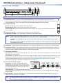
NOTE: Smaller matrix sizes have fewer input buttons, output buttons, or both.
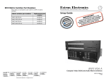
a Infrared remote sensor — This sensor receives infrared (IR) signals from the optional IR 501 small matrix universal
IR
30°
remote control. Point the IR remote control within 30 degrees of this sensor for best results. Operation of the switcher
using the IR 501 remote control is described in the IR 501 Small Matrix IR Remote Control User Guide.
b Power/data/audio LED —
When lit, indicates that power is applied to the matrix switcher.
1
When blinking off and on, indicates that an IR signal has been received.
In Audio Setup mode, serves as an audio meter that is tied to output 1 (see “Viewing and Adjusting the Audio Input
Gain” on page 4).
c Input buttons and LEDs — The input buttons and LEDs select and identify inputs.
d Output buttons and LEDs — The output buttons and LEDs select and identify outputs.
INPUT/OUTPUT SELECTION
2
3
4
5
6
7
8
9
0
+10
ENTER
PRESET
SAVE
VIDEO
AUDIO
MUTE
UNMUTE
INPUT
OUTPUT
IR 501
SMALL MATRIX REMOTE
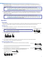
NOTES: • The input and output buttons and LEDs also serve as preset selection buttons and indicators, allowing you to select
presets to either save or recall (see “Saving or Recalling a Preset” on the next page).
• The Output 1 through Output 3 LEDs also serve as input audio level indicators, each indicating a range of 6 dB
when lit.
• On 8-output switchers, the Output 7 and Output 8 buttons and LEDs also serve as the Down (<) and Up (>) controls
and indicators. See j and k.
e Enter button — The Enter button saves changes when you set up a new configuration (see “Creating a Tie“ on the next page).
f Preset button and LED — The Preset button activates either Save Preset mode or Recall Preset mode. Save Preset mode saves a
configuration as a preset. Recall Preset mode recalls and activates a previously-defined preset. The Preset button indicates Save
Preset mode when it is blinking and Recall Preset mode when it lights steadily.
g I/O and Audio Setup button —
Press and release — Cycles through video and audio, video only, or audio only for input and output selection. See the Video and
Audio LEDs (h) for the sequence.
Press and hold — The I/O button also serves as the Audio Setup mode selection button. To enable the Audio Setup mode, press and
hold the Audio Setup button for about 2 seconds until the Audio Setup LED (i) lights. In Audio Setup mode, you can view and
change the current audio level setting for each input (see “Viewing and Adjusting the Audio Input Gain” on page 4).
Audio Setup mode times out after approximately 30 seconds of inactivity.
h Video/+dB LED and Audio/–dB LED —
I/O selection — The Video and Audio LEDs indicate
whether video and audio, video only, or audio only are
selected using the input buttons (c) and output buttons
(d). Pressing the I/O button advances through a cycle of
video and/or audio selection.
MVX SERIES
VGA/AUDIO MATRIX SWITCHER
VID
+dB
VID
+dB
VID
+dB
VID
+dB
AUD
- dB
AUD
- dB
AUD
- dB
AUD
- dB
I/O
VID
+dB
AUD
- dB
AUDIO SETUP
Press
Default
Press
Video Only
Press
Audio Only
Press
Video and
Audio
Audio Setup mode — The –dB and +dB LEDs indicate the
polarity of the audio level setting (see “Viewing and Adjusting the Audio Input Gain” on page 4). Both LEDs light to indicate
unity gain (0 dB).
i Audio Setup LED — The Audio Setup LED lights red to indicate that the switcher is in Audio Setup mode (see “Viewing and
Adjusting the Audio Input Gain” on page 4).
NOTE: The Audio Setup LED also indicates errors when you use an IR 501 small matrix remote control. The LED lights for
approximately 1 second when the switcher receives an unexpected or out-of-sequence IR command from the remote
control. The switcher otherwise ignores the command.
2