1
Summit 200 Series Switch
Installation and User Guide
Software Version 7.1e0
Extreme Networks, Inc.
3585 Monroe Street
Santa Clara, California 95051
(888) 257-3000
http://www.extremenetworks.com
December, 2003
Part Number: 100149-00 Rev 02
©2003 Extreme Networks, Inc. All rights reserved. Extreme Networks, ExtremeWare and BlackDiamond are registered
trademarks of Extreme Networks, Inc. in the United States and certain other jurisdictions. ExtremeWare Vista,
ExtremeWorks, ExtremeAssist, ExtremeAssist1, ExtremeAssist2, PartnerAssist, Extreme Standby Router Protocol, ESRP,
SmartTraps, Alpine, Summit, Summit1, Summit4, Summit4/FX, Summit7i, Summit24, Summit48, Summit Virtual
Chassis, SummitLink, SummitGbX, SummitRPS and the Extreme Networks logo are trademarks of Extreme Networks,
Inc., which may be registered or pending registration in certain jurisdictions. The Extreme Turbodrive logo is a service
mark of Extreme Networks, which may be registered or pending registration in certain jurisdictions. Specifications are
subject to change without notice.
NetWare and Novell are registered trademarks of Novell, Inc. Merit is a registered trademark of Merit Network, Inc.
Solaris is a trademark of Sun Microsystems, Inc. F5, BIG/ip, and 3DNS are registered trademarks of F5 Networks, Inc.
see/IT is a trademark of F5 Networks, Inc.
“Data Fellows”, the triangle symbol, and Data Fellows product names and symbols/logos are
trademarks of Data Fellows.
F-Secure SSH is a registered trademark of Data Fellows.
All other registered trademarks, trademarks and service marks are property of their respective owners.
ii
Contents
Preface
Chapter 1
Chapter 2
Introduction
xiii
Conventions
xiv
Related Publications
xiv
Summit 200 Series Switch Overview
Summit 200 Series Switches
15
Summary of Features
15
Summit 200-24 Switch Physical Features
Summit 200-24 Switch Front View
Summit 200-24 Switch Rear View
16
16
19
Summit 200-48 Switch Physical Features
Summit 200-48 Switch Front View
Summit 200-48 Switch Rear View
19
19
22
Mini-GBIC Type and Hardware/Software Support
Mini-GBIC Type and Specifications
23
23
Switch Installation
Determining the Switch Location
27
Following Safety Information
28
Installing the Switch
Rack Mounting
Free-Standing
Desktop Mounting of Multiple Switches
28
28
29
29
Installing or Replacing a Mini-Gigabit Interface Connector (Mini-GBIC)
Safety Information
Preparing to Install or Replace a Mini-GBIC
Removing and Inserting a Mini-GBIC
29
29
29
30
Summit 200 Series Switch Installation and User Guide
iii
Contents
Chapter 3
Chapter 4
iv
Creating a Stack
31
Connecting Equipment to the Console Port
32
Powering On the Switch
34
Checking the Installation
34
Logging In for the First Time
34
ExtremeWare Overview
Summary of Features
Virtual LANs (VLANs)
Spanning Tree Protocol
Quality of Service
Unicast Routing
Load Sharing
ESRP-Aware Switches
37
38
38
39
39
39
39
Software Licensing
Feature Licensing
40
40
Security Licensing for Features Under License Control
SSH2 Encryption
41
41
Software Factory Defaults
42
Accessing the Switch
Understanding the Command Syntax
Syntax Helper
Command Shortcuts
Summit 200 Series Switch Numerical Ranges
Names
Symbols
45
46
46
46
47
47
Line-Editing Keys
47
Command History
48
Common Commands
48
Configuring Management Access
User Account
Administrator Account
Default Accounts
Creating a Management Account
50
50
51
51
52
Domain Name Service Client Services
53
Checking Basic Connectivity
Ping
Traceroute
54
54
54
Summit 200 Series Switch Installation and User Guide
Contents
Chapter 5
Chapter 6
Managing the Switch
Overview
57
Using the Console Interface
58
Using Telnet
Connecting to Another Host Using Telnet
Configuring Switch IP Parameters
Disconnecting a Telnet Session
Controlling Telnet Access
58
58
58
60
61
Using Secure Shell 2 (SSH2)
Enabling SSH2
61
61
Using SNMP
Accessing Switch Agents
Supported MIBs
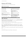
Configuring SNMP Settings
Displaying SNMP Settings
62
62
62
62
64
Authenticating Users
RADIUS Client
Configuring TACACS+
64
64
69
Network Login
Web-Based and 802.1x Authentication
Campus and ISP Modes
Interoperability Requirements
Multiple Supplicant Support
Exclusions and Limitations
Configuring Network Login
Web-Based Authentication User Login Using Campus Mode
DHCP Server on the Switch
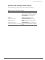
Displaying DHCP Information
Displaying Network Login Settings
Disabling Network Login
Additional Configuration Details
Network Login Configuration Commands
Displaying Network Login Settings
Disabling Network Login
71
71
73
74
75
75
76
77
79
79
79
79
79
80
81
81
Using EAPOL Flooding
81
Using the Simple Network Time Protocol
Configuring and Using SNTP
SNTP Configuration Commands
SNTP Example
82
82
85
85
Configuring Ports on a Switch
Enabling and Disabling Switch Ports
Summit 200 Series Switch Installation and User Guide
87
v
Contents
Configuring Switch Port Speed and Duplex Setting
Switch Port Commands
Chapter 7
Load Sharing on the Switch
Load-Sharing Algorithms
Configuring Switch Load Sharing
Load-Sharing Example
Verifying the Load-Sharing Configuration
91
92
93
93
94
Switch Port-Mirroring
Port-Mirroring Commands
Port-Mirroring Example
94
95
95
Setting Up a Redundant Gigabit Uplink Port
95
Extreme Discovery Protocol
EDP Commands
95
96
Virtual LANs (VLANs)
Overview of Virtual LANs
Benefits
Chapter 8
vi
88
89
97
97
Types of VLANs
Port-Based VLANs
Tagged VLANs
98
98
100
VLAN Names
Default VLAN
Renaming a VLAN
102
102
103
Configuring VLANs on the Switch
VLAN Configuration Commands
VLAN Configuration Examples
103
103
104
Displaying VLAN Settings
104
MAC-Based VLANs
MAC-Based VLAN Guidelines
MAC-Based VLAN Limitations
MAC-Based VLAN Example
Timed Configuration Download for MAC-Based VLANs
105
105
106
106
106
Forwarding Database (FDB)
Overview of the FDB
FDB Contents
FDB Entry Types
How FDB Entries Get Added
Associating a QoS Profile with an FDB Entry
109
109
109
110
110
Configuring FDB Entries
FDB Configuration Examples
111
111
Summit 200 Series Switch Installation and User Guide
Contents
Displaying FDB Entries
Chapter 9
Chapter 10
112
Access Policies
Overview of Access Policies
Access Control Lists
Rate Limits
Routing Access Policies
115
115
115
116
Using Access Control Lists
Access Masks
Access Lists
Rate Limits
How Access Control Lists Work
Access Mask Precedence Numbers
Specifying a Default Rule
The permit-established Keyword
Adding Access Mask, Access List, and Rate Limit Entries
Deleting Access Mask, Access List, and Rate Limit Entries
Verifying Access Control List Configurations
Access Control List Commands
Access Control List Examples
116
116
116
117
118
118
118
118
119
120
120
120
124
Using Routing Access Policies
Creating an Access Profile
Configuring an Access Profile Mode
Adding an Access Profile Entry
Deleting an Access Profile Entry
Applying Access Profiles
Routing Access Policies for RIP
Routing Access Policies for OSPF
128
128
128
128
129
129
129
131
Making Changes to a Routing Access Policy
132
Removing a Routing Access Policy
132
Routing Access Policy Commands
133
Network Address Translation (NAT)
Overview
135
Internet IP Addressing
136
Configuring VLANs for NAT
NAT Modes
136
137
Configuring NAT
138
Configuring NAT Rules
138
Creating NAT Rules
Creating Static and Dynamic NAT Rules
139
139
Summit 200 Series Switch Installation and User Guide
vii
Contents
Creating Portmap NAT Rules
Creating Auto-Constrain NAT Rules
Advanced Rule Matching
Configuring Timeouts
Chapter 11
Chapter 12
viii
139
140
140
141
Displaying NAT Settings
141
Disabling NAT
142
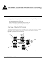
Ethernet Automatic Protection Switching
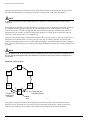
Overview of the EAPS Protocol
Optimizing Interoperability
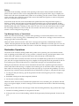
Fault Detection and Recovery
Restoration Operations
143
145
145
146
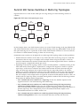
Summit 200 Series Switches in Multi-ring Topologies
147
Commands for Configuring and Monitoring EAPS
Creating and Deleting an EAPS Domain
Defining the EAPS Mode of the Switch
Configuring EAPS Polling Timers
Configuring the Primary and Secondary Ports
Configuring the EAPS Control VLAN
Configuring the EAPS Protected VLANs
Enabling and Disabling an EAPS Domain
Enabling and Disabling EAPS
Unconfiguring an EAPS Ring Port
Displaying EAPS Status Information
148
149
149
149
150
151
151
152
152
152
152
Quality of Service (QoS)
Overview of Policy-Based Quality of Service
157
Applications and Types of QoS
Video Applications
Critical Database Applications
Web Browsing Applications
File Server Applications
158
158
158
158
159
Configuring QoS for a Port or VLAN
159
Traffic Groupings
Access List Based Traffic Groupings
MAC-Based Traffic Groupings
Explicit Class of Service (802.1p and DiffServ) Traffic Groupings
Configuring DiffServ
Physical and Logical Groupings
159
160
160
161
163
166
Verifying Configuration and Performance
QoS Monitor
Displaying QoS Profile Information
167
167
167
Summit 200 Series Switch Installation and User Guide
Contents
Chapter 13
Chapter 14
Chapter 15
Modifying a QoS Configuration
168
Traffic Rate-Limiting
168
Dynamic Link Context System
DLCS Guidelines
DLCS Limitations
DLCS Commands
168
169
169
169
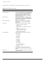
Status Monitoring and Statistics
Status Monitoring
171
Port Statistics
173
Port Errors
173
Port Monitoring Display Keys
174
Setting the System Recovery Level
175
Logging
Local Logging
Remote Logging
Logging Configuration Changes
Logging Commands
175
176
177
178
178
RMON
About RMON
RMON Features of the Switch
Configuring RMON
Event Actions
179
179
180
181
181
Spanning Tree Protocol (STP)
Overview of the Spanning Tree Protocol
183
Spanning Tree Domains
Defaults
STPD BPDU Tunneling
183
184
184
STP Configurations
184
Configuring STP on the Switch
STP Configuration Example
186
189
Displaying STP Settings
189
Disabling and Resetting STP
189
IP Unicast Routing
Overview of IP Unicast Routing
Router Interfaces
Populating the Routing Table
Subnet-Directed Broadcast Forwarding
Summit 200 Series Switch Installation and User Guide
191
192
193
194
ix
Contents
Chapter 16
x
Proxy ARP
ARP-Incapable Devices
Proxy ARP Between Subnets
194
195
195
Relative Route Priorities
195
Configuring IP Unicast Routing
Verifying the IP Unicast Routing Configuration
196
196
IP Commands
197
Routing Configuration Example
201
Displaying Router Settings
202
Resetting and Disabling Router Settings
203
Configuring DHCP/BOOTP Relay
Verifying the DHCP/BOOTP Relay Configuration
204
204
UDP-Forwarding
Configuring UDP-Forwarding
UDP-Forwarding Example
ICMP Packet Processing
UDP-Forwarding Commands
205
205
205
206
206
Interior Gateway Routing Protocols
Overview
RIP Versus OSPF
207
208
Overview of RIP
Routing Table
Split Horizon
Poison Reverse
Triggered Updates
Route Advertisement of VLANs
RIP Version 1 Versus RIP Version 2
208
209
209
209
209
209
209
Overview of OSPF
Link-State Database
Areas
Point-to-Point Support
210
210
211
214
Route Re-Distribution
Configuring Route Re-Distribution
OSPF Timers and Authentication
215
215
216
Configuring RIP
217
RIP Configuration Example
219
Displaying RIP Settings
220
Resetting and Disabling RIP
220
Configuring OSPF
220
Summit 200 Series Switch Installation and User Guide
Contents
Configuring OSPF Wait Interval
Chapter 17
Chapter 18
Chapter 19
225
Displaying OSPF Settings
OSPF LSD Display
226
226
Resetting and Disabling OSPF Settings
227
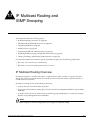
IP Multicast Routing and IGMP Snooping
IP Multicast Routing Overview
229
PIM Sparse Mode (PIM-SM) Overview
230
Configuring PIM-SM
Enabling and Disabling PIM-SM
PIM-SM Commands
230
231
232
IGMP Overview
233
Configuring IGMP and IGMP Snooping
234
Displaying IGMP Snooping Configuration Information
235
Clearing, Disabling, and Resetting IGMP Functions
235
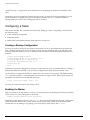
Configuring Stacked Switches
Introducing Stacking
237
Configuring a Stack
Creating a Backup Configuration
Enabling the Master
Enabling a Stack Member
Configuring Ports and VLANS on Stacks
238
238
238
239
240
Recovering a Stack
242
Changing a Stack Configuration
Stack Configuration Commands
Running Features on a Stack
243
244
245
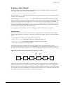
Testing Images for a Stack
245
Using the Console for Managing the Stack
246
Setting the Command Prompt
246
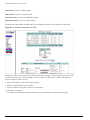
Using ExtremeWare Vista
on the Summit 200
ExtremeWare Vista Overview
Setting Up Your Browser
247
247
Accessing ExtremeWare Vista
248
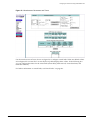
Navigating within ExtremeWare Vista
Browser Controls
250
251
Summit 200 Series Switch Installation and User Guide
xi
Contents
Status Messages
Appendix A
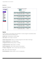
Configuring the Summit 200 using ExtremeWare Vista
IP Forwarding
License
OSPF
Ports
RIP
SNMP
Spanning Tree
Switch
User Accounts
Virtual LAN
251
252
253
254
261
263
266
267
271
271
272
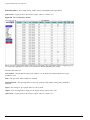
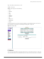
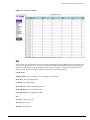
Reviewing ExtremeWare Vista Statistical Reports
Event Log
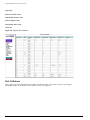
FDB
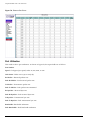
IP ARP
IP Configuration
IP Route
IP Statistics
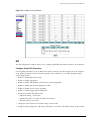
Ports
Port Collisions
Port Errors
Port Utilization
RIP
Switch
274
275
276
277
278
280
281
283
284
285
286
287
288
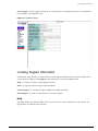
Locating Support Information
Help
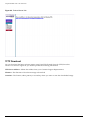
TFTP Download
289
289
290
Logging Out of ExtremeWare Vista
293
Safety Information
Important Safety Information
Power
Power Cord
Connections
Lithium Battery
Appendix B
Appendix C
xii
251
295
295
296
296
296
Technical Specifications
Summit 200-24 Switch
299
Summit 200-48 Switch
302
Supported Standards
Summit 200 Series Switch Installation and User Guide
Contents
Appendix D
Appendix E
Software Upgrade and Boot Options
Downloading a New Image
Rebooting the Switch
307
308
Saving Configuration Changes
Returning to Factory Defaults
309
310
Using TFTP to Upload the Configuration
310
Using TFTP to Download the Configuration
Downloading a Complete Configuration
Downloading an Incremental Configuration
Scheduled Incremental Configuration Download
Remember to Save
311
311
311
311
312
Upgrading and Accessing BootROM
Upgrading BootROM
Accessing the BootROM menu
312
312
312
Boot Option Commands
313
Troubleshooting
LEDs
233
Using the Command-Line Interface
Port Configuration
VLANs
STP
234
235
236
237
Debug Tracing
237
TOP Command
237
Contacting Extreme Technical Support
237
Index
Index of Commands
Summit 200 Series Switch Installation and User Guide
xiii
Contents
xiv
Summit 200 Series Switch Installation and User Guide
Preface
This preface provides an overview of this guide, describes guide conventions, and lists other
publications that may be useful.
Introduction
This guide provides the required information to install the Summit 200 series switch and configure the
ExtremeWare™ software running on the Summit 200 series switch.
This guide is intended for use by network administrators who are responsible for installing and setting
up network equipment. It assumes a basic working knowledge of:
• Local area networks (LANs)
• Ethernet concepts
• Ethernet switching and bridging concepts
• Routing concepts
• Internet Protocol (IP) concepts
• Simple Network Management Protocol (SNMP)
NOTE
If the information in the release notes shipped with your switch differs from the information in this guide,
follow the release notes.
Summit 200 Series Switch Installation and User Guide
xiii
Conventions
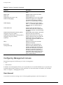
Table 1 and Table 2 list conventions that are used throughout this guide.
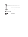
Table 1: Notice Icons
Icon
Notice Type
Alerts you to...
Note
Important features or instructions.
Caution
Risk of personal injury, system damage, or loss of data.
Warning
Risk of severe personal injury.
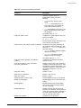
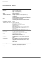
Table 2: Text Conventions
Convention
Description
Screen displays
This typeface indicates command syntax, or represents information as
it appears on the screen.
The words “enter”
and “type”
When you see the word “enter” in this guide, you must type something,
and then press the Return or Enter key. Do not press the Return or
Enter key when an instruction simply says “type.”
[Key] names
Key names are written with brackets, such as [Return] or [Esc].
If you must press two or more keys simultaneously, the key names are
linked with a plus sign (+). Example:
Press [Ctrl]+[Alt]+[Del].
Words in italicized type
Italics emphasize a point or denote new terms at the place where they
are defined in the text.
Related Publications
The publications related to this one are:
• ExtremeWare Release Notes
• Summit 200 Series Switch Release Notes
Documentation for Extreme Networks products is available on the World Wide Web at the following
location:
• http://www.extremenetworks.com/
xiv
Summit 200 Series Switch Installation and User Guide
1
Summit 200 Series Switch Overview
This chapter describes the features and functionality of the Summit 200 series switches:
• Summit 200 Series Switches on page 15
• Summary of Features on page 15
• Summit 200-24 Switch Physical Features on page 16
• Summit 200-48 Switch Physical Features on page 19
• Mini-GBIC Type and Hardware/Software Support on page 23
Summit 200 Series Switches
The Summit 200 series switches include the following switch models:
• Summit 200-24 switch
• Summit 200-48 switch
Summary of Features
The Summit 200 series switches support the following ExtremeWare features:
• Virtual local area networks (VLANs) including support for IEEE 802.1Q and IEEE 802.1p
• Spanning Tree Protocol (STP) (IEEE 802.1D)
• Quality of Service (QoS) including support for IEEE 802.1p, MAC QoS, and four hardware queues
• Wire-speed Internet Protocol (IP) routing
• DHCP/BOOTP Relay
• Network Address Translation (NAT)
• Extreme Standby Router Protocol (ESRP) - Aware support
• Ethernet Automated Protection Switching (EAPS) support
• Routing Information Protocol (RIP) version 1 and RIP version 2
• Open Shortest Path First (OSPF) routing protocol
• DiffServ support
Summit 200 Series Switch Installation and User Guide
15
Summit 200 Series Switch Overview
• Access-policy support for routing protocols
• Access list support for packet filtering
• Access list support for rate-limiting
• IGMP snooping to control IP multicast traffic
• Load sharing on multiple ports
• RADIUS client and per-command authentication support
• TACACS+ support
• Network login
• Console command-line interface (CLI) connection
• Telnet CLI connection
• SSH2 connection
• Simple Network Management Protocol (SNMP) support
• Remote Monitoring (RMON)
• Traffic mirroring for ports
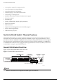
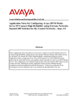
Summit 200-24 Switch Physical Features
The Summit 200-24 switch is a compact enclosure (see Figure 1) one rack unit in height (1.75 inches or
44.45 mm) that provides 24 autosensing 10BASE-T/100BASE-TX ports using RJ-45 connectors. It also
provides two 10/100/1000BASE-T Gigabit Ethernet uplink ports using RJ-45 connectors and two optical
ports that also allow Gigabit Ethernet uplink connections through Extreme 1000BASE-SX, 1000BASE-LX,
or 1000BASE-ZX Small Form Factor pluggable (SFP) Gigabit Interface Connectors (GBICs)—also known
as mini-GBICs—using LC optical fiber connectors.
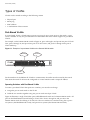
Summit 200-24 Switch Front View
Figure 1 shows the Summit 200-24 switch front view.
Figure 1: Summit 200-24 switch front view
10/100 Mbps ports
Mini-GBIC
port status LEDs
1000-baseT ports
Unit stacking Console
port
ID LED
Mini-GBIC ports
LC24001A
NOTE
See Table 5 for information about supported mini-GBIC types and distances.
16
Summit 200 Series Switch Installation and User Guide
Summit 200-24 Switch Physical Features
NOTE
See “Summit 200-24 Switch LEDs” on page 18 for more details.
Console Port
Use the console port (9-pin, “D” type connector) for connecting a terminal and carrying out local
management.
Port Connections
The Summit 200-24 switch has 24 10BASE-T/100BASE-TX ports using RJ-45 connectors for
communicating with end stations and other devices over 10/100Mbps Ethernet.
The switch also has four Gigabit Ethernet uplink ports. These ports are labeled 25 and 26 on the front
panel of the switch. Two of the ports are 10/100/1000BASE-T ports using RJ-45 connectors. The other
two ports are unpopulated receptacles for mini-SFP GBICs, using optical fibers with LC connectors. The
Summit 200-24 switch supports the use of 1000BASE-SX, 1000BASE-LX, or 1000BASE-ZX mini-GBICs.
NOTE
Only mini-GBICs that have been certified by Extreme Networks (available from Extreme Networks)
should be inserted into the mini-GBIC receptacles on the Summit 200 series switch.
Only two of the four Gigabit Ethernet uplink ports can be active at one time. For example, you can use
both 1000BASE-T ports, both mini-GBIC ports, or a combination of one 1000BASE-T port and one
mini-GBIC.
NOTE
For information on the mini-GBIC, see “Mini-GBIC Type and Hardware/Software Support” on page 23.
Summit 200-24 Switch Uplink Redundancy
Gigabit Ethernet uplink redundancy on the Summit 200-24 switch follows these rules:
• Ports 25 and 26 are Gigabit Ethernet ports that have redundant PHY interfaces, one mini-GBIC and
one 1000BASE-T connection for each port.
• Each of the uplink Gigabit Ethernet ports (25 and 26) can use either the mini-GBIC or the
1000BASE-T interface, but not both simultaneously.
• Only one interface on each port can be active at a time. For example, on port 25, with both the
mini-GBIC and 1000BASE-T interfaces connected, only one interface can be activated. The other is
inactive. If both interfaces are connected, the switch defaults to the fiber interface (mini-GBIC) and
deactivates the 1000BASE-T interface.
• If only one interface is connected, the switch activates the connected interface.
• To set up a redundant link on port 25, connect the active fibre and 1000BASE-T links to both the
RJ-45 and mini-GBIC interfaces of port 25. The switch defaults to the fiber link. If the fiber link fails
during operation, the switch automatically activates the redundant 1000BASE-T link.
Summit 200 Series Switch Installation and User Guide
17
Summit 200 Series Switch Overview
NOTE
To support automatic failover between the fiber and copper ports, you must use an Extreme mini-GBIC
connector.
Full-Duplex
The Summit 200-24 switch provides full-duplex support for all ports. Full-duplex allows frames to be
transmitted and received simultaneously and, in effect, doubles the bandwidth available on a link. All
10/100 Mbps ports on the Summit 200-24 switch autonegotiate for half- or full-duplex operation.
Summit 200-24 Switch LEDs
Table 3 describes the light emitting diode (LED) behavior on the Summit 200-24 switch.
Table 3: Summit 200-24 switch LED behavior
Unit Status LED (MGMT LED)
Color
Indicates
Green slow
blinking
The Summit switch is operating normally.
Green fast
blinking
The Summit switch POST is in progress.
Amber
The Summit switch has failed its POST or an overheat condition
is detected.
Color
Indicates
Green
The fan is operating normally.
Fan LED
Amber blinking A failed condition is present on the fan.
Port Status LEDs (Ports 1–26)
Color
Indicates
Green
Link is present; port is enabled.
Green blinking
Link is present, port is enabled, and there is activity on the port.
Off
Link is not present or the port is disabled.
Media-Selection (Fiber) LEDs (Ports 25 and 26)
Color
Indicates
Green
Fiber link is selected; mini-GBIC is present and being used for the
Gigabit Ethernet uplink.
Off
1000BASE-T link is selected; the switch is using the RJ-45 port
for the Gigabit Ethernet uplink.
Unit Stacking ID Number LED
Color
Indicates
0
N/A
Either stacking is not enabled or the stack is down.
1
N/A
The switch is the stack master.
2-8
N/A
The switch is a member of the stack.
18
Summit 200 Series Switch Installation and User Guide
Summit 200-48 Switch Physical Features
Summit 200-24 Switch Rear View
Figure 2 shows the rear view of the Summit 200-24 switch.
Figure 2: Summit 200-24 switch rear view
Power socket
LC24002
Power Socket
The Summit 200-24 switch automatically adjusts to the supply voltage. The power supply operates
down to 90 V.
Serial Number
Use this serial number for fault-reporting purposes.
MAC Address
This label shows the unique Ethernet MAC address assigned to this device.
NOTE
The Summit 200-24 switch certification and safety label is located on the bottom of the switch.
Summit 200-48 Switch Physical Features
The Summit 200-48 switch is a compact enclosure (see Figure 3) one rack unit in height (1.75 inches or
44.45 mm) that provides 48 autosensing 10BASE-T/100BASE-TX ports using RJ-45 connectors. It also
provides two 10/100/1000BASE-T Gigabit Ethernet uplink ports using RJ-45 connectors and two optical
ports that also allow Gigabit Ethernet uplink connections through Extreme 1000BASE-SX, 1000BASE-LX,
or 1000BASE-ZX SFP mini-GBICs using optical fibers with LC connectors.
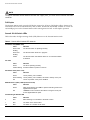
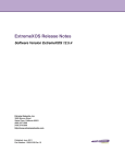
Summit 200-48 Switch Front View
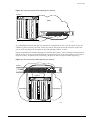
Figure 3 shows the Summit 200-48 switch front view.
Summit 200 Series Switch Installation and User Guide
19
Summit 200 Series Switch Overview
Figure 3: Summit 200-48 switch front view
Mini-GBIC ports
10/100 Mbps ports
Console
port
1000-baseT ports
LC48001
NOTE
See Table 5 for information about supported mini-GBIC types and distances.
NOTE
See “Summit 200-48 Switch LEDs” on page 22 for more details.
Console Port
Use the console port (9-pin, “D” type connector) for connecting a terminal and carrying out local
management.
Port Connections
The Summit 200-48 switch has 48 10BASE-T/100BASE-TX ports using RJ-45 connectors for
communicating with end stations and other devices over 10/100Mbps Ethernet.
The switch also has four Gigabit Ethernet uplink ports. These ports are labeled 49 and 50 on the front
panel of the switch. Two of the ports are 10/100/1000BASE-T ports using RJ-45 connectors. The other
two ports are unpopulated receptacles for mini-SFP GBICs, using optical fibers with LC connectors. The
Summit 200-48 switch supports the use of 1000BASE-SX, 1000BASE-LX, or 1000BASE-ZX mini-GBICs.
NOTE
Only mini-GBICs that have been certified by Extreme Networks (available from Extreme Networks)
should be inserted into the mini-GBIC receptacles on the Summit 200 series switch.
Only two of the four Gigabit Ethernet uplink ports can be active at one time. For example, you can use
both 1000BASE-T ports, both mini-GBIC ports, or a combination of one 1000BASE-T port and one
mini-GBIC.
NOTE
For information on the mini-GBIC, see “Mini-GBIC Type and Hardware/Software Support” on page 23.
20
Summit 200 Series Switch Installation and User Guide
Summit 200-48 Switch Physical Features
NOTE
When configuring the Summit 200-48 switch, all ports specified as mirrored ports and mirroring port, or
ACL ingress ports and egress port, must belong to the same port group. Port group 1 consists of ports
1 through 24 and port 49; port group 2 consists of ports 25 through 48 and port 50.
Gigabit Ethernet Port Failover Speed
The Summit 200-48 switch Gigabit Ethernet port failover from the fiber link to the copper link takes 3-4
seconds. The Summit 200-48 switch Gigabit Ethernet port failover from the copper link to the fiber link
takes 1-2 seconds.
Summit 200-48 Switch Uplink Redundancy
Gigabit Ethernet uplink redundancy on the Summit 200-48 switch follows these rules:
• Ports 49 and 50 are Gigabit Ethernet ports that have redundant PHY interfaces, one mini-GBIC and
one 1000BASE-T connection for each port.
• Each of the uplink Gigabit Ethernet ports (49 and 50) can use either the mini-GBIC or
the1000BASE-T interface, but not both simultaneously.
• Only one interface on each port can be active at a time. For example, on port 49, with both the
mini-GBIC and 1000BASE-T interfaces connected, only one interface can be activated. The other is
inactive. If both interfaces are connected, the switch defaults to the fiber interface (mini-GBIC) and
deactivates the 1000BASE-T interface.
• If only one interface is connected, the switch activates the connected interface.
• To set up a redundant link on port 49, connect the active fibre and 1000BASE-T links to both the
RJ-45 and mini-GBIC interfaces of port 49. The switch defaults to the fiber link. If the fiber link fails
during operation, the switch automatically activates the redundant 1000BASE-T link.
NOTE
To support automatic failover between the fiber and copper ports, you must use an Extreme mini-GBIC
connector.
Full-Duplex
The Summit 200-48 switch provides full-duplex support for all ports. Full-duplex allows frames to be
transmitted and received simultaneously and, in effect, doubles the bandwidth available on a link. All
10/100 Mbps ports on the Summit 200-48 switch autonegotiate for half- or full-duplex operation.
Summit 200 Series Switch Installation and User Guide
21
Summit 200 Series Switch Overview
Summit 200-48 Switch LEDs
Table 4 describes the LED behavior on the Summit 200-48 switch.
Table 4: Summit 200-48 switch LED behavior
Unit Status LED (MGMT LED)
Color
Indicates
Green slow
blinking
The Summit switch is operating normally.
Green fast
blinking
The Summit switch POST is in progress.
Amber
The Summit switch has failed its POST or an overheat condition
is detected.
Color
Indicates
Green
The fan is operating normally.
Fan LED
Amber blinking A failed condition is present on the fan.
Port Status LEDs (Ports 1–50)
Color
Indicates
Green
Link is present; port is enabled.
Green blinking
Link is present, port is enabled, and there is activity on the port.
Off
Link is not present or the port is disabled.
Media-Selection (Fiber) LEDs (Ports 49 and 50)
Color
Indicates
Green
Fiber link is selected; mini-GBIC is present and being used for the
Gigabit Ethernet uplink.
Off
1000BASE-T link is selected; the switch is using the RJ-45 port
for the Gigabit Ethernet uplink.
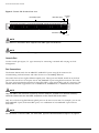
Summit 200-48 Switch Rear View
Figure 4 shows the rear view of the Summit 200-48 switch.
Figure 4: Summit 200-48 switch rear view
Power socket
LC48002
Power Socket
The Summit 200-48 switch automatically adjusts to the supply voltage. The power supply operates
down to 90 V.
22
Summit 200 Series Switch Installation and User Guide
Mini-GBIC Type and Hardware/Software Support
Serial Number
Use this serial number for fault-reporting purposes.
MAC Address
This label shows the unique Ethernet MAC address assigned to this device.
NOTE
The Summit 200-48 switch certification and safety label is located on the bottom of the switch.
Mini-GBIC Type and Hardware/Software Support
The Summit 200 series switch supports the SFP GBIC, also known as the mini-GBIC, in three types: the
SX mini-GBIC, which conforms to the 1000BASE-SX standard, the LX mini-GBIC, which conforms to the
1000BASE-LX standard, and the ZX mini-GBIC, a long-haul mini-GBIC that conforms to the IEEE 802.3z
standard. The system uses identifier bits to determine the media type of the mini-GBIC that is installed.
The Summit 200 series switches support only the SFP mini-GBIC.
NOTE
Only mini-GBICs that have been certified by Extreme Networks (available from Extreme Networks)
should be inserted into the mini-GBIC receptacles on the Summit 200 series switch.
This section describes the mini-GBIC types and specifications.
Mini-GBIC Type and Specifications
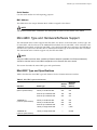
Table 5 describes the mini-GBIC type and distances for the Summit 200 series switches.
Table 5: Mini-GBIC types and distances
Maximum
Distance
(Meters)
Standard
Media Type
Mhz•Km
Rating
1000BASE-SX
(850 nm optical window)
50/125 µm multimode fiber
400
500
50/125 µm multimode fiber
500
550
62.5/125 µm multimode fiber
160
220
62.5/125 µm multimode fiber
200
275
50/125 µm multimode fiber
400
550
50/125 µm multimode fiber
500
550
62.5/125 µm multimode fiber
500
550
10/125 µm single-mode fiber
—
5,000
10/125 µm single-mode fiber
—
50,000
1000BASE-LX
(1310 nm optical window)
1000BASE-ZX
(1550 nm optical window)
Summit 200 Series Switch Installation and User Guide
23
Summit 200 Series Switch Overview
SX Mini-GBIC Specifications
Table 6 describes the specifications for the SX mini-GBIC.
Table 6: SX mini-GBIC specifications
Parameter
Minimum
Typical
Maximum
Transceiver
Optical output power
–9.5 dBm
Center wavelength
830 nm
–4 dBm
850 nm
860 nm
Receiver
Optical input power sensitivity
–21 dBm
Optical input power maximum
Operating wavelength
–4 dBm
830 nm
860 nm
General
Total system budget
11.5 dB
Total optical system budget for the SX mini-GBIC is 11.5 dB. Extreme Networks recommends that 3 dB
of the total budget be reserved for losses induced by cable splices, connectors, and operating margin.
While 8.5 dB remains available for cable-induced attenuation, the 1000BASE-SX standard specifies
supported distances of 275 meters over 62.5 micron multimode fiber and 550 meters over 50 micron
multimode fiber. There is no minimum attenuation or minimum cable length restriction.
LX Mini-GBIC Specifications
Table 7 describes the specifications for the LX mini-GBIC.
Table 7: LX mini-GBIC specifications
Parameter
Minimum
Typical
Maximum
Transceiver
Optical output power
–9.5 dBm
Center wavelength
1275 nm
–3 dBm
1310 nm
1355 nm
Receiver
Optical input power sensitivity
–23 dBm
Optical input power maximum
Operating wavelength
–3 dBm
1270 nm
1355 nm
General
Total system budget
13.5 dB
Total optical system budget for the LX mini-GBIC is 13.5 dB. Measure cable plant losses with a 1310 nm
light source and verify this to be within budget. When calculating the maximum distance attainable
using optical cable with a specified loss per kilometer (for example 0.25 dB/km) Extreme Networks
recommends that 3 dB of the total budget be reserved for losses induced by cable splices, connectors,
and operating margin. Thus, 10.5 dB remains available for cable induced attenuation. There is no
minimum attenuation or minimum cable length restriction.
24
Summit 200 Series Switch Installation and User Guide
Mini-GBIC Type and Hardware/Software Support
ZX Mini-GBIC Specifications
Table 8 describes the specifications for the ZX mini-GBIC.
Table 8: ZX mini-GBIC specifications
Parameter
Minimum
Typical
Maximum
Optical output power
–2 dBm
0 dBm
3 dBm
Center wavelength
1540 nm
1550 nm
1570 nm
Transceiver
Receiver
Optical input power sensitivity
–23 dBm
Optical input power maximum
Operating wavelength
–3 dBm
1540 nm
1550 nm
1570 nm
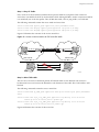
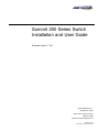
Long Range GBIC System Budgets
Measure cable plant losses with a 1550 nm light source and verify this to be within budget. When
calculating the maximum distance attainable using optical cable with a specified loss per kilometer (for
example 0.25 dB/km), Extreme Networks recommends that 3 dB of the total budget be reserved for
losses induced by cable splices, connectors, and operating margin. Figure 5 shows the total optical
system budget between long range GBICs in various end-to-end combinations (ZX, ZX Rev 03, LX70,
and LX100).
NOTE
The ZX mini-GBIC is equivalent to the ZX Rev 03 GBIC.
Figure 5: Total optical system budgets for long range GBICs
ZX GBIC
LX70
19.5 dB
22.0 dB
23.0 dB
LX70
20.0 dB
ZX GBIC
ZX GBIC
Rev. 03
LX70
LX100
ZX GBIC
Rev. 03
LX70
LX70
ZX GBIC
23.5 dB
19.0 dB
ZX GBIC
ZX GBIC
Rev. 03
ZX GBIC
Rev. 03
21.5 dB
30.0 dB
ZX GBIC
Rev. 03
LX100
29.0 dB
18.0 dB
ZX GBIC
21.0 dB
23.0 dB
LX100
25.0 dB
24.5 dB
LX100
27.0 dB
24.0 dB
LX100
XM_041
Summit 200 Series Switch Installation and User Guide
25
Summit 200 Series Switch Overview
Table 9 lists the minimum attenuation requirements to prevent saturation of the receiver for each type of
long range GBIC.
Table 9: Minimum attenuation requirements
Receivers
Transceivers
26
GBIC Type
LX70
LX100
ZX (prior to
Rev 03)
ZX Rev 03
ZX mini
LX70
9 dB
13 dB
7 dB
7 dB
9 dB
LX100
8 dB
12 dB
6 dB
6 dB
8 dB
ZX (prior to
Rev 03)
2 dB
6 dB
0 dB
0 dB
2 dB
ZX Rev 03
5 dB
9 dB
3 dB
3 dB
5 dB
ZX mini
6 dB
10 dB
4 dB
4 dB
6 dB
Summit 200 Series Switch Installation and User Guide
2
Switch Installation
This chapter describes the following topics:
• Determining the Switch Location on page 27
• Following Safety Information on page 28
• Installing the Switch on page 28
• Creating a Stack on page 31
• Installing or Replacing a Mini-Gigabit Interface Connector (Mini-GBIC) on page 29
• Connecting Equipment to the Console Port on page 32
• Powering On the Switch on page 34
• Checking the Installation on page 34
• Logging In for the First Time on page 34
CAUTION
Use of controls or adjustments of performance or procedures other than those specified herein can
result in hazardous radiation exposure.
Determining the Switch Location
The Summit 200 series switch is suited for use in the office, where it can be free-standing or mounted in
a standard 19-inch equipment rack. Alternately, the device can be rack-mounted in a wiring closet or
equipment room. Two mounting brackets are supplied with the switch.
When deciding where to install the switch, ensure that:
• The switch is accessible and cables can be connected easily.
• Water or moisture cannot enter the case of the unit.
• Air-flow around the unit and through the vents in the side of the case is not restricted. You should
provide a minimum of 1 inch (25 mm) clearance.
• No objects are placed on top of the unit.
• Units are not stacked more than four high if the switch is free-standing.
Summit 200 Series Switch Installation and User Guide
27
Switch Installation
Following Safety Information
Before installing or removing any components of the switch, or before carrying out any maintenance
procedures, read the safety information provided in w of this guide.
Installing the Switch
The Summit 200 series switch switch can be mounted in a rack, or placed free-standing on a tabletop.
Rack Mounting
CAUTION
Do not use the rack mount kits to suspend the switch from under a table or desk, or to attach the switch
to a wall.
To rack mount the Summit 200 series switch:
1 Place the switch upright on a hard flat surface, with the front facing you.
2 Remove the existing screws from the sides of the case (retain the screws for Step 4).
3 Locate a mounting bracket over the mounting holes on one side of the unit.
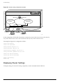
4 Insert the screws and fully tighten with a suitable screwdriver, as shown in Figure 6.
Figure 6: Fitting the mounting bracket
LC24003
5 Repeat steps 2 through 4 for the other side of the switch.
6 Insert the switch into the 19-inch rack.
7 Secure the switch with suitable screws (not provided).
8 Connect the switch to the redundant power supply (if applicable).
9 Connect cables.
28
Summit 200 Series Switch Installation and User Guide
Installing or Replacing a Mini-Gigabit Interface Connector (Mini-GBIC)
Free-Standing
The Summit 200 series switch is supplied with four self-adhesive rubber pads. Apply the pads to the
underside of the device by sticking a pad in the marked area at each corner of the switch.
Desktop Mounting of Multiple Switches
You can physically place up to four Summit switches on top of one another.
NOTE
This relates only to stacking the devices directly one on top of one another.
Apply the pads to the underside of the device by sticking a pad at each corner of the switch. Place the
devices on top of one another, ensuring that the corners align.
Installing or Replacing a Mini-Gigabit Interface Connector
(Mini-GBIC)
This section describes the safety precautions and preparation steps that you must perform before
inserting and securing a mini-GBIC.
Safety Information
Before you install or replace a mini-GBIC, read the safety information in this section.
WARNING!
Mini-GBICs can emit invisible laser radiation. Avoid direct eye exposure to beam.
Mini-GBICs are a class 1 laser device. Use only devices approved by Extreme Networks.
NOTE
Remove the LC fiber-optic connector from the mini-GBIC prior to removing the mini-GBIC from the
switch.
Preparing to Install or Replace a Mini-GBIC
To ensure proper installation, complete the following tasks before inserting the mini-GBIC:
• Disable the port that is needed to install or replace the mini-GBIC.
• Inspect and clean the fiber tips, coupler, and connectors.
• Prepare and clean an external attenuator, if needed.
• Do not stretch the fiber.
Summit 200 Series Switch Installation and User Guide
29
Switch Installation
• Make sure the bend radius of the fiber is not less than 2 inches.
In addition to the previously described tasks, Extreme Networks recommends the following when
installing or replacing mini-GBICs on an active network:
• Use the same type of mini-GBIC at each end of the link.
• Connect one end of the link to the Tx port. Without an attenuator, measure the total loss from the Tx
port to the other side of the link.
Once you complete all of the described tasks, you are ready to install or replace a mini-GBIC.
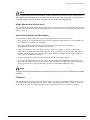
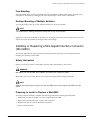
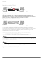
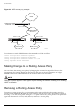
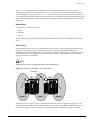
Removing and Inserting a Mini-GBIC
You can remove mini-GBICs from, or insert mini-GBICs into your Summit 200 series switch without
powering off the system. Figure 7 shows the two types of mini-GBIC modules.
Figure 7: Mini-GBIC modules
Module A
Module B
XM_024
Mini-GBICs are a 3.3 V Class 1 laser device. Use only devices approved by Extreme Networks.
WARNING!
Mini-GBICs can emit invisible laser radiation. Avoid direct eye exposure to beam.
NOTE
Remove the LC fiber-optic connector from the mini-GBIC prior to removing the mini-GBIC from the
switch.
NOTE
If you see an amber blinking Mini-GBIC port status LED on your Summit 200 series switch, the
mini-GBIC installed in your switch is one that is not approved or supported by Extreme Networks. To
correct this problem, ensure that you install a mini-GBIC that is approved and supported by Extreme
Networks.
30
Summit 200 Series Switch Installation and User Guide
Creating a Stack
Removing a Mini-GBIC
To remove a mini-GBIC similar to the one labeled “Module A” in Figure 7, gently press and hold the
black plastic tab at the bottom of the connector to release the mini-GBIC, and pull the mini-GBIC out of
the SFP receptacle on the switch.
To remove a mini-GBIC similar to the one labeled “Module B” in Figure 7, rotate the front handle down
and pull the mini-GBIC out of the slot.
Inserting a Mini-GBIC
NOTE
Mini-GBICs can be installed in the SFP mini-GBIC receptacles for ports 25 and 26 on the Summit 200
series switches.
To insert a mini-GBIC connector:
1 Holding the mini-GBIC by its sides, insert the mini-GBIC into the SFP receptacle on the switch.
2 Push the mini-GBIC into the SFP receptacle until you hear an audible click, indicating the mini-GBIC
is securely seated in the SFP receptacle. If the mini-GBIC has a handle, push up on the handle to
secure the mini-GBIC.
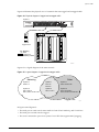
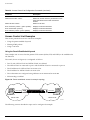
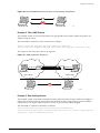
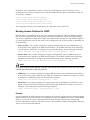
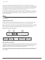
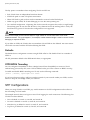
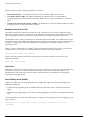
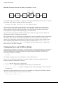
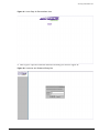
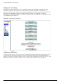
Creating a Stack
You can physically cable as many as eight Summit 200 switches together to create a virtual chassis
called as stack. You can mix any combination of Summit 200-24 and Summit 200-48 within the stack. The
high-speed one Gigabit Ethernet ports are the backplane of the stack and are called stacking ports. By
creating a stack, users can access and manage the devices using a single IP address.
The stacking configuration retains a high speed port on the end switches as uplinks to the network.
However, these uplink ports may not be configured to be in a load share group. Load sharing is only
supported for ports on the same switch. An example of a stacking configuration is shown in Figure 8.
Summit 200 Series Switch Installation and User Guide
31
Switch Installation
Figure 8: Stacking Summit 200-48
To upstream
routers and switches
To downstream
switches
ES2K001
Connecting Equipment to the Console Port
Connection to the console port is used for direct local management. The switch console port settings are
set as follows:
• Baud rate—9600
• Data bits—8
• Stop bit—1
• Parity—None
• Flow control—None
NOTE
If you set the switch console port flow control to XON/XOFF rather than None, you will be unable to
access the switch. Do not set the switch console port flow control to XON/XOFF.
The terminal connected to the console port on the switch must be configured with the same settings.
This procedure is described in the documentation supplied with the terminal.
32
Summit 200 Series Switch Installation and User Guide
Connecting Equipment to the Console Port
Appropriate cables are available from your local supplier. To make your own cables, pinouts for a DB-9
male console connector are described in Table 10.
Table 10: Console Connector Pinouts
Function
Pin Number
Direction
DCD (data carrier detect)
1
In
RXD (receive data)
2
In
TXD (transmit data)
3
Out
DTR (data terminal ready)
4
Out
GND (ground)
5
—
DSR (data set ready)
6
In
RTS (request to send)
7
Out
CTS (clear to send
8
In
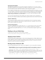
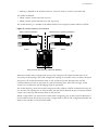
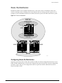
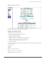
Figure 9 shows the pin-outs for a 9-pin to RS-232 25-pin null-modem cable.
Figure 9: Null-modem cable pin-outs
Summit
PC/Terminal
Cable connector: 9-pin female
Cable connector: 25-pin male/female
Screen Shell
TxD
3
RxD
2
Ground
5
RTS
7
CTS
8
DSR
6
DCD
1
DTR
4
1
3
2
7
4
20
5
6
8
Screen
RxD
TxD
Ground
RTS
DTR
CTS
DSR
DCD
ser_sum1
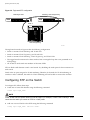
Figure 10 shows the pin-outs for a 9-pin to 9-pin PC-AT null-modem serial cable.
Figure 10: PC-AT serial null-modem cable pin-outs
Summit
PC-AT Serial Port
Cable connector: 9-pin female
Cable connector: 9-pin female
Screen Shell
DTR
4
TxD
3
RxD
2
CTS
8
Ground
5
DSR
6
RTS
7
DCD
1
Summit 200 Series Switch Installation and User Guide
Shell Screen
DCD
1
RxD
2
TxD
3
DTR
4
Ground
5
DSR
6
RTS
7
CTS
8
ser_sum2
33
Switch Installation
Powering On the Switch
To turn on power to the switch, connect the AC power cable to the switch and then to the wall outlet.
Turn the on/off switch to the on position.
Checking the Installation
After turning on power to the Summit 200 series switch, the device performs a Power On Self-Test
(POST).
During the POST, all ports are temporarily disabled, the port LED is off, and the MGMT LED flashes.
The MGMT LED flashes until the switch successfully passes the POST.
If the switch passes the POST, the MGMT LED is blinking slowly (once per second). If the switch fails
the POST, the MGMT LED is amber.
NOTE
For more information on the LEDs, see Chapter 1, “Summit 200 Series Switch Overview”.
Logging In for the First Time
After the Summit 200 series switch completes the POST, it is operational. Once operational, you can log
in to the switch and configure an IP address for the default VLAN (named default).
To configure the IP settings manually, follow these steps:
1 Connect a terminal or workstation running terminal-emulation software to the console port.
2 At your terminal, press [Return] one or more times until you see the login prompt.
3 At the login prompt, enter the default user name admin to log on with administrator privileges.
For example:
login: admin
Administrator capabilities allow you to access all switch functions.
NOTE
For more information on switch security, see Chapter 4, “Accessing the Switch”.
4 At the password prompt, press [Return].
The default name, admin, has no password assigned. When you have successfully logged on to the
switch, the command-line prompt displays the name of the switch (for example, Summit200-24) in its
prompt.
5 Assign an IP address and subnetwork mask for VLAN default by typing
config vlan default ipaddress 123.45.67.8 255.255.255.0
Your changes take effect immediately.
6 Save your configuration changes so that they will be in effect after the next switch reboot, by typing
34
Summit 200 Series Switch Installation and User Guide
Logging In for the First Time
save
NOTE
For more information on saving configuration changes, see the ExtremeWare Software User Guide.
7 When you are finished using the facility, logout of the switch by typing
logout
NOTE
After two incorrect login attempts, the Summit 200 series switch locks you out of the login facility. You
must wait a few minutes before attempting to log in again.
Summit 200 Series Switch Installation and User Guide
35
Switch Installation
36
Summit 200 Series Switch Installation and User Guide
3
ExtremeWare Overview
This chapter describes the following topics:
• Summary of Features on page 37
• Software Licensing on page 40
• Security Licensing for Features Under License Control on page 41
• Software Factory Defaults on page 42
ExtremeWare is the full-featured software operating system that is designed to run on the Summit 200
series switch. This section describes the supported ExtremeWare features for the Summit 200 series
switch.
Summary of Features
The Summit 200 series switch supports the following ExtremeWare features:
• Virtual local area networks (VLANs) including support for IEEE 802.1Q and IEEE 802.1p
• Spanning Tree Protocol (STP) (IEEE 802.1D)
• Quality of Service (QoS) including support for IEEE 802.1p, MAC QoS, and four hardware queues
• Wire-speed Internet Protocol (IP) routing
• DHCP/BOOTP Relay
• Network Address Translation (NAT)
• Extreme Standby Router Protocol (ESRP) - Aware support
• Ethernet Automated Protection Switching (EAPS) support
• Routing Information Protocol (RIP) version 1 and RIP version 2
• Open Shortest Path First (OSPF) routing protocol
• Diffserv support
• Access-policy support for routing protocols
• Access list support for packet filtering
• Access list support for rate-limiting
• IGMP snooping to control IP multicast traffic
• Load sharing on multiple ports
Summit 200 Series Switch Installation and User Guide
37
ExtremeWare Overview
• RADIUS client and per-command authentication support
• TACACS+ support
• Network login
• Console command-line interface (CLI) connection
• Telnet CLI connection
• SSH2 connection
• Simple Network Management Protocol (SNMP) support
• Remote Monitoring (RMON)
• Traffic mirroring for ports
Virtual LANs (VLANs)
ExtremeWare has a VLAN feature that enables you to construct your broadcast domains without being
restricted by physical connections. A VLAN is a group of location- and topology-independent devices
that communicate as if they were on the same physical local area network (LAN).
Implementing VLANs on your network has the following three advantages:
• They help to control broadcast traffic. If a device in VLAN Marketing transmits a broadcast frame,
only VLAN Marketing devices receive the frame.
• They provide extra security. Devices in VLAN Marketing can only communicate with devices on
VLAN Sales using routing services.
• They ease the change and movement of devices on networks.
NOTE
For more information on VLANs, see Chapter 7, “Virtual LANs (VLANs)”.
Spanning Tree Protocol
The Summit 200 series switch supports the IEEE 802.1D Spanning Tree Protocol (STP), which is a
bridge-based mechanism for providing fault tolerance on networks. STP enables you to implement
parallel paths for network traffic, and ensure that:
• Redundant paths are disabled when the main paths are operational.
• Redundant paths are enabled if the main traffic paths fail.
A single spanning tree can span multiple VLANs.
NOTE
For more information on STP, see Chapter 14, “Spanning Tree Protocol (STP)”.
38
Summit 200 Series Switch Installation and User Guide
Summary of Features
Quality of Service
ExtremeWare has Quality of Service (QoS) features that support IEEE 802.1p, MAC QoS, and four
queues. These features enable you to specify service levels for different traffic groups. By default, all
traffic is assigned the “normal” QoS policy profile. If needed, you can create other QoS policies and
rate-limiting access control lists and apply them to different traffic types so that they have different
maximum bandwidth, and priority.
NOTE
For more information on Quality of Service, see Chapter 12, “Quality of Service (QoS)”.
Unicast Routing
The Summit 200 series switch can route IP traffic between the VLANs that are configured as virtual
router interfaces. Static IP routes are maintained in the routing table. The following routing protocols
are supported:
• RIP version 1
• RIP version 2
• OSPF
NOTE
For more information on IP unicast routing, see Chapter 15, “IP Unicast Routing”.
Load Sharing
Load sharing allows you to increase bandwidth and resiliency by using a group of ports to carry traffic
in parallel between systems. The sharing algorithm allows the switch to use multiple ports as a single
logical port. For example, VLANs see the load-sharing group as a single virtual port. The algorithm also
guarantees packet sequencing between clients.
On stacked configurations, load sharing is not supported through the stacking port. Members of a load
sharing group must reside on the same slot.
NOTE
For information on load sharing, see Chapter 6, “Configuring Ports on a Switch”.
ESRP-Aware Switches
Extreme switches that are not running ESRP, but are connected on a network that has other Extreme
switches running ESRP are ESRP-aware. When ESRP-aware switches are attached to ESRP-enabled
switches, the ESRP-aware switches reliably perform fail-over and fail-back scenarios in the prescribed
recovery times. No configuration of this feature is necessary.
Summit 200 Series Switch Installation and User Guide
39
ExtremeWare Overview
If Extreme switches running ESRP are connected to layer 2 switches that are not manufactured by
Extreme Networks (or Extreme switches that are not running ExtremeWare 4.0 or above), the fail-over
times seen for traffic local to the segment may appear longer, depending on the application involved
and the FDB timer used by the other vendor’s layer 2 switch. As such, ESRP can be used with layer 2
switches from other vendors, but the recovery times vary.
The VLANs associated with the ports connecting an ESRP-aware switch to an ESRP-enabled switch
must be configured using an 802.1Q tag on the connecting port, or, if only a single VLAN is involved, as
untagged using the protocol filter any. ESRP will not function correctly if the ESRP-aware switch
interconnection port is configured for a protocol-sensitive VLAN using untagged traffic.
ESRP routing is supported in stacked configurations only on the master switch.
Software Licensing
Some Extreme Networks products have capabilities that are enabled by using a license key. Keys are
typically unique to the switch, and are not transferable. Keys are stored in NVRAM and, once entered,
persist through reboots, software upgrades, and reconfigurations. The following sections describe the
features that are associated with license keys.
Feature Licensing
Summit 200 series switches support software licensing for different levels of functionality. In
ExtremeWare version 6.2e.2, feature support is separated into two sets: Edge and Advanced Edge. Edge
is a subset of Advanced Edge.
Edge Functionality
Edge functionality requires no license key. Summit 200 series switches have Edge functionality without
the requirement of a license key. Edge functionality includes all switching functions, and also includes
all available layer 3 QoS, access list, and ESRP-aware functions. Layer 3 routing functions include
support for:
• IP routing using RIP version 1 and/or RIP version 2
• IP routing between directly attached VLANs
• IP routing using static routes
Advanced Edge Functionality
The Advanced Edge license enables support of additional functions, including:
• Rate-limiting ACLs
• IP routing using OSPF
• EAPS Edge (cannot be a core node on the ring)
• Network login
• RADIUS and TACACS+ command authentication
• Network Address Translation (NAT)
40
Summit 200 Series Switch Installation and User Guide
Security Licensing for Features Under License Control
Enabling the Advanced Edge Functionality
To enable the Advanced Edge software feature license, use the following command:
enable license advanced-edge <license_key>
where license_key is an integer.
NOTE
The command unconfig switch all does not clear licensing information. Once it is enabled on the
switch, this license cannot be disabled.
Verifying the Advanced Edge License
To verify the Advanced Edge license, use the show switch command.
Obtaining an Advanced Edge License
You can order the desired functionality from the factory, using the appropriate model of the desired
product. If you order licensing from the factory, the switch arrives packaged with a certificate that
contains the unique license key(s), and instructions for enabling the correct functionality on the switch.
The certificate is typically packaged with the switch documentation. Once the license key is entered, it
should not be necessary to enter the information again. However, we recommend keeping the certificate
for your records.
You can upgrade the Advanced Edge licensing of an existing product by purchasing a voucher for the
desired product and functionality. Please contact your supplier to purchase a voucher.
The voucher contains information and instructions on obtaining a license key for the switch using the
Extreme Networks Support website at:
http://esupport.extremenetworks.com
or by phoning Extreme Networks Technical Support at:
• (800) 998-2408
• (408) 579-2826
Security Licensing for Features Under License Control
Certain additional ExtremeWare security features, such as the use of Secure Shell (SSH2) encryption,
might be under United States export restriction control. Extreme Networks ships these security features
in a disabled state. In order to enable the use of these features, you must first obtain an export license,
which you can do through Extreme Networks (at no extra charge).
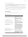
SSH2 Encryption
ExtremeWare version 6.0 and above supports the SSH2 protocol. SSH2 allows the encryption of Telnet
session data. The encryption methods used are under U.S. export restriction control.
To obtain information on enabling SSH2 encryption, access the Extreme Networks Support website at:
Summit 200 Series Switch Installation and User Guide
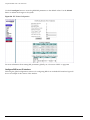
41
ExtremeWare Overview
http://esupport.extremenetworks.com
Fill out a contact form to indicate compliance or noncompliance with the export restrictions. If you are
in compliance, you will be given information that will allow you to enable security features.
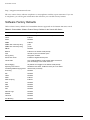
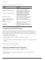
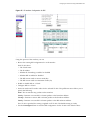
Software Factory Defaults
Table 11 shows factory defaults for ExtremeWare features supported on the Summit 200 series switch.
Table 11: ExtremeWare Software Feature Factory Defaults for the Summit 200 Series
Item
Default Setting
Serial or Telnet user account
admin with no password and user with no password
Telnet
Enabled
SSH2
Disabled
SNMP
Enabled
SNMP read community string
public
SNMP write community string
private
RMON
Disabled
BOOTP
Enabled on the default VLAN (default)
QoS
All traffic is part of the default queue
802.1p priority
Recognition enabled
802.3x flow control
Enabled on Gigabit Ethernet ports
Virtual LANs
Two VLANs predefined. VLAN named default contains all
ports and belongs to the STPD named s0
802.1Q tagging
All packets are untagged on the default VLAN (default)
Spanning Tree Protocol
Disabled for the switch; enabled for each port in the STPD
Forwarding database aging period
300 seconds (5 minutes)
IP Routing
Disabled
RIP
Disabled
OSPF
Disabled
IGMP
Enabled
IGMP snooping
Enabled
NTP
Disabled
DNS
Disabled
EAPS
Disabled
NAT
Disabled
Network Login
Disabled
RADIUS
Disabled
TACACS+
Disabled
Port Mirroring
Disabled
42
Summit 200 Series Switch Installation and User Guide
Software Factory Defaults
NOTE
For default settings of individual ExtremeWare features, see the applicable individual chapters in this
guide.
Summit 200 Series Switch Installation and User Guide
43
ExtremeWare Overview
44
Summit 200 Series Switch Installation and User Guide
4
Accessing the Switch
This chapter describes the following topics:
• Understanding the Command Syntax on page 45
• Line-Editing Keys on page 47
• Command History on page 48
• Common Commands on page 48
• Configuring Management Access on page 50
• Domain Name Service Client Services on page 53
• Checking Basic Connectivity on page 54
Understanding the Command Syntax
This section describes the steps to take when entering a command. Refer to the sections that follow for
detailed information on using the command-line interface.
When entering a command at the prompt, ensure that you have the appropriate privilege level. Most
configuration commands require you to have the administrator privilege level. To use the command-line
interface (CLI), follow these steps:
1 Enter the command name.
If the command does not include a parameter or values, skip to step 3. If the command requires
more information, continue to step 2.
2 If the command includes a parameter, enter the parameter name and values.
3 The value part of the command specifies how you want the parameter to be set. Values include
numerics, strings, or addresses, depending on the parameter.
4 After entering the complete command, press [Return].
NOTE
If an asterisk (*) appears in front of the command-line prompt, it indicates that you have outstanding
configuration changes that have not been saved. For more information on saving configuration changes,
see Appendix D, “Software Upgrade and Boot Options”.
Summit 200 Series Switch Installation and User Guide
45
Accessing the Switch
Syntax Helper
The CLI has a built-in syntax helper. If you are unsure of the complete syntax for a particular command,
enter as much of the command as possible and press [Return]. The syntax helper provides a list of
options for the remainder of the command.
The syntax helper also provides assistance if you have entered an incorrect command.
Command Completion with Syntax Helper
ExtremeWare provides command completion by way of the [Tab] key. If you enter a partial command,
pressing the [Tab] key posts a list of available options, and places the cursor at the end of the command.
Abbreviated Syntax
Abbreviated syntax is the most unambiguous, shortest allowable abbreviation of a command or
parameter. Typically, this is the first three letters of the command.
In command tables throughout this guide, abbreviated syntax is noted using bold characters.
NOTE
When using abbreviated syntax, you must enter enough characters to make the command
unambiguous and distinguishable to the switch.
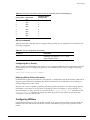
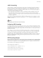
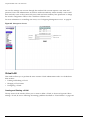
Command Shortcuts
All named components of the switch configuration must have a unique name. Components are named
using the create command. When you enter a command to configure a named component, you do not
need to use the keyword of the component. For example, to create a VLAN, you must enter a unique
VLAN name:
create vlan engineering
Once you have created the VLAN with a unique name, you can then eliminate the keyword vlan from
all other commands that require the name to be entered. For example, on the stand-alone switch,
instead of entering the command
config vlan engineering delete port 1-3,6
you could enter the following shortcut:
config engineering delete port 1-3,6
Summit 200 Series Switch Numerical Ranges
Commands that require you to enter one or more port numbers on a Summit 200 series switch use the
parameter <portlist> in the syntax. A portlist can be a range of numbers, for example:
port 1-3
You can add additional port numbers to the list, separated by a comma:
port 1-3,6,8
46
Summit 200 Series Switch Installation and User Guide
Line-Editing Keys
Names
All named components of the switch configuration must have a unique name. Names must begin with
an alphabetical character and are delimited by whitespace, unless enclosed in quotation marks.
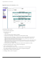
Symbols
You may see a variety of symbols shown as part of the command syntax. These symbols explain how to
enter the command, and you do not type them as part of the command itself. Table 12 summarizes
command syntax symbols.
Table 12: Command Syntax Symbols
Symbol
Description
< > (angle brackets) Enclose a variable or value. You must specify the variable or value. For
example, in the syntax
config vlan <name> ipaddress <ip_address>
you must supply a VLAN name for <name> and an address for
<ip_address> when entering the command. Do not type the angle
brackets.
[ ] (square brackets) Enclose a required value or list of required arguments. One or more
values or arguments can be specified. For example, in the syntax
use image [primary | secondary]
you must specify either the primary or secondary image when entering
the command. Do not type the square brackets.
| (vertical bar)
Separates mutually exclusive items in a list, one of which must be
entered. For example, in the syntax
config snmp community [read-only | read-write]
<string>
you must specify either the read or write community string in the
command. Do not type the vertical bar.
{ } (braces)
Enclose an optional value or a list of optional arguments. One or more
values or arguments can be specified. For example, in the syntax
reboot {<date> <time> | cancel}
you can specify either a particular date and time combination, or the
keyword cancel to cancel a previously scheduled reboot. If you do not
specify an argument, the command will prompt, asking if you want to
reboot the switch now. Do not type the braces.
Line-Editing Keys
Table 13 describes the line-editing keys available using the CLI.
Table 13: Line-Editing Keys
Keystroke
Description
Backspace
Deletes character to left of cursor and shifts remainder of line to left.
Delete or [Ctrl] + D
Deletes character under cursor and shifts remainder of line to left.
[Ctrl] + K
Deletes characters from under cursor to end of line.
Summit 200 Series Switch Installation and User Guide
47
Accessing the Switch
Table 13: Line-Editing Keys (continued)
Keystroke
Description
Insert
Toggles on and off. When toggled on, inserts text and shifts previous text
to right.
Left Arrow
Moves cursor to left.
Right Arrow
Moves cursor to right.
Home or [Ctrl] + A
Moves cursor to first character in line.
End or [Ctrl] + E
Moves cursor to last character in line.
[Ctrl] + L
Clears screen and movers cursor to beginning of line.
[Ctrl] + P or
Up Arrow
Displays previous command in command history buffer and places cursor
at end of command.
[Ctrl] + N or
Down Arrow
Displays next command in command history buffer and places cursor at
end of command.
Command History
ExtremeWare “remembers” the last 49 commands you entered. You can display a list of these
commands by using the following command:
history
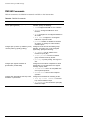
Common Commands
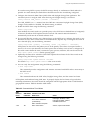
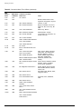
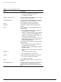
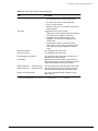
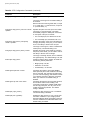
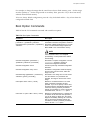
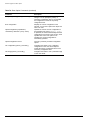
Table 14 describes common commands used to manage the switch. Commands specific to a particular
feature are described in the other chapters of this guide.
Table 14: Common Commands
Command
Description
clear session <number>
Terminates a Telnet session from the
switch.
config account <username> {encrypted}
{<password>}
Configures a user account password.
Passwords must have a minimum of 1
character and can have a maximum of 32
characters. User names and passwords
are case-sensitive.
config banner
Configures the banner string. You can
enter up to 24 rows of 79-column text that
is displayed before the login prompt of
each session. Press [Return] at the
beginning of a line to terminate the
command and apply the banner. To clear
the banner, press [Return] at the beginning
of the first line.
config ports <portlist> auto off {speed [10 | 100 |
1000]} duplex [half | full]
Manually configures the port speed and
duplex setting of one or more ports on a
switch.
config ssh2 key {pregenerated}
Generates the SSH2 host key.
48
Summit 200 Series Switch Installation and User Guide
Common Commands
Table 14: Common Commands (continued)
Command
Description
config sys-recovery-level [none | critical | all]
Configures a recovery option for instances
where an exception occurs in
ExtremeWare. Specify one of the
following:
•
none—Recovery without system
reboot.
•
critical—ExtremeWare logs an
error to the syslog, and reboots the
system after critical exceptions.
•
all—ExtremeWare logs an error to the
syslog, and reboots the system after
any exception.
The default setting is none.
config time <date> <time>
Configures the system date and time. The
format is as follows:
mm/dd/yyyy hh:mm:ss
The time uses a 24-hour clock format. You
cannot set the year past 2036.
config timezone <gmt_offset> {autodst | noautodst}
Configures the time zone information to
the configured offset from GMT time. The
format of gmt_offset is +/- minutes from
GMT time. Specify:
•
autodst—Enables automatic Daylight
Savings Time change.
•
noautodst—Disables automatic
Daylight Savings Time change.
The default setting is autodst.
config vlan <name> ipaddress <ip_address>
{<mask>}
Configures an IP address and subnet
mask for a VLAN.
create account [admin | user] <username>
{encrypted} {<password>}
Creates a user account. This command is
available to admin-level users and to users
with RADIUS command authorization. The
username is between 1 and 32 characters,
the password is between 0 and 16
characters.
create vlan <name>
Creates a VLAN.
delete account <username>
Deletes a user account.
delete vlan <name>
Deletes a VLAN.
disable bootp vlan [<name> | all]
Disables BOOTP for one or more VLANs.
disable cli-config-logging
Disables logging of CLI commands to the
Syslog.
disable clipaging
Disables pausing of the screen display
when a show command output reaches
the end of the page.
disable idletimeouts
Disables the timer that disconnects all
sessions. Once disabled, console sessions
remain open until the switch is rebooted or
you logoff. Telnet sessions remain open
until you close the Telnet client.
disable ports <portlist>
Disables a port on the switch.
Summit 200 Series Switch Installation and User Guide
49
Accessing the Switch
Table 14: Common Commands (continued)
Command
Description
disable ssh2
Disables SSH2 Telnet access to the
switch.
disable telnet
Disables Telnet access to the switch.
disable web
Disables web access.
enable bootp vlan [<name> | all]
Enables BOOTP for one or more VLANs.
enable cli-config-logging
Enables the logging of CLI configuration
commands to the Syslog for auditing
purposes. The default setting is enabled.
enable clipaging
Enables pausing of the screen display
when show command output reaches the
end of the page. The default setting is
enabled.
enable idletimeouts
Enables a timer that disconnects all
sessions (both Telnet and console) after
20 minutes of inactivity. The default setting
is disabled.
enable ssh2 {access-profile [<access_profile> |
none]} {port <tcp_port_number>}
Enables SSH2 Telnet sessions. By default,
SSH2 uses TCP port number 22.
enable telnet {access-profile [<access_profile> |
none]} {port <tcp_port_number>}
Enables Telnet access to the switch. By
default, Telnet uses TCP port number 23.
enable web
Enables web server on the switch for
network login support. By default, the web
server is enabled.
history
Displays the previous 49 commands
entered on the switch.
show banner
Displays the user-configured banner.
unconfig switch {all}
Resets all switch parameters (with the
exception of defined user accounts, and
date and time information) to the factory
defaults. If you specify the keyword all,
the switch erases the currently selected
configuration image in flash memory and
reboots. As a result, all parameters are
reset to default settings.
Configuring Management Access
ExtremeWare supports the following two levels of management:
• User
• Administrator
In addition to the management levels, you can optionally use an external RADIUS server to provide CLI
command authorization checking for each command. For more information on RADIUS, see “RADIUS
Client” in Chapter 5, “Managing the Switch”.
User Account
A user-level account has viewing access to all manageable parameters, with the exception of:
50
Summit 200 Series Switch Installation and User Guide
Configuring Management Access
• User account database.
• SNMP community strings.
A user-level account can use the ping command to test device reachability, and change the password
assigned to the account name. If you have logged on with user capabilities, the command-line prompt
ends with a (>) sign. For example:
Summit200-24:2>
Administrator Account
An administrator-level account can view and change all switch parameters. It can also add and delete
users, and change the password associated with any account name. The administrator can disconnect a
management session that has been established by way of a Telnet connection. If this happens, the user
logged on by way of the Telnet connection is notified that the session has been terminated.
If you have logged on with administrator capabilities, the command-line prompt ends with a (#) sign.
For example:
Summit200-24:18#
Prompt Text
The prompt text is taken from the SNMP sysname setting. The number that follows the colon indicates
the sequential line/command number.
If an asterisk (*) appears in front of the command-line prompt, it indicates that you have outstanding
configuration changes that have not been saved. For example:
*Summit200-24:19#
Default Accounts
By default, the switch is configured with two accounts, as shown in Table 15.
Table 15: Default Accounts
Account Name
Access Level
admin
This user can access and change all manageable parameters. The
admin account cannot be deleted.
user
This user can view (but not change) all manageable parameters, with
the following exceptions:
•
This user cannot view the user account database.
•
This user cannot view the SNMP community strings.
Changing the Default Password
Default accounts do not have passwords assigned to them. Passwords must have a minimum of four
characters and can have a maximum of 12 characters.
Summit 200 Series Switch Installation and User Guide
51
Accessing the Switch
NOTE
User names and passwords are case-sensitive.
To add a password to the default admin account, follow these steps:
1 Log in to the switch using the name admin.
2 At the password prompt, press [Return].
3 Add a default admin password by entering the following command:
config account admin
4 Enter the new password at the prompt.
5 Re-enter the new password at the prompt.
To add a password to the default user account, follow these steps:
1 Log in to the switch using the name admin.
2 At the password prompt, press [Return], or enter the password that you have configured for the
admin account.
3 Add a default user password by entering the following command:
config account user
4 Enter the new password at the prompt.
5 Re-enter the new password at the prompt.
NOTE
If you forget your password while logged out of the command-line interface, contact your local technical
support representative, who will advise on your next course of action.
Creating a Management Account
The switch can have a total of 16 management accounts. You can use the default names (admin and
user), or you can create new names and passwords for the accounts. Passwords can have a minimum of
0 characters and can have a maximum of 31 characters.
To create a new account, follow these steps:
1 Log in to the switch as admin.
2 At the password prompt, press [Return], or enter the password that you have configured for the
admin account.
3 Add a new user by using the following command:
create account [admin | user] <username>
4 Enter the password at the prompt.
5 Re-enter the password at the prompt.
52
Summit 200 Series Switch Installation and User Guide
Domain Name Service Client Services
Viewing Accounts
To view the accounts that have been created, you must have administrator privileges. Use the following
command to see the accounts:
show accounts
Deleting an Account
To delete a account, you must have administrator privileges. To delete an account, use the following
command:
delete account <username>
NOTE
The account name admin cannot be deleted.
Domain Name Service Client Services
The Domain Name Service (DNS) client in ExtremeWare augments the following commands to allow
them to accept either IP addresses or host names:
• telnet
• download [bootrom | configuration | image]
• upload configuration
• ping
• traceroute
In addition, the nslookup utility can be used to return the IP address of a hostname.
Table 16 describes the commands used to configure DNS.
Table 16: DNS Commands
Command
Description
config dns-client add <ipaddress>
Adds a DNS name server(s) to the
available server list for the DNS client. Up
to three name servers can be configured.
config dns-client default-domain <domain_name>
Configures the domain that the DNS client
uses if a fully qualified domain name is not
entered. For example, if the default
domain is configured to be foo.com,
executing ping bar searches for
bar.foo.com.
config dns-client delete <ipaddress>
Removes a DNS server.
nslookup <hostname>
Displays the IP address of the requested
host.
show dns-client
Displays the DNS configuration.
Summit 200 Series Switch Installation and User Guide
53
Accessing the Switch
Checking Basic Connectivity
The switch offers the following commands for checking basic connectivity:
• ping
• traceroute
Ping
The ping command enables you to send Internet Control Message Protocol (ICMP) echo messages to a
remote IP device. The ping command is available for both the user and administrator privilege level.
The ping command syntax is:
ping {continuous} {size <start_size> {- <end_size>}} [<ip_address> | <hostname>] {from
<src_address> | with record-route | from <src_ipaddress> with record-route}
Options for the ping command are described in Table 17.
Table 17: Ping Command Parameters
Parameter
Description
continuous
Specifies ICMP echo messages to be sent continuously. This
option can be interrupted by pressing any key.
size
Specifies the size of the ICMP request. If both the start_size
and end_size are specified, transmits ICMP requests using 1 byte
increments, per packet. If no end_size is specified, packets of
start_size are sent.
<ipaddress>
Specifies the IP address of the host.
<hostname>
Specifies the name of the host. To use the hostname, you must
first configure DNS.
from
Uses the specified source address in the ICMP packet. If not
specified, the address of the transmitting interface is used.
with record-route
Decodes the list of recorded routes and displays them when the
ICMP echo reply is received.
If a ping request fails, the switch continues to send ping messages until interrupted. Press any key to
interrupt a ping request.
Traceroute
The traceroute command enables you to trace the routed path between the switch and a destination
endstation. The traceroute command syntax is:
traceroute [<ip_address> | <hostname>] {from <src_ipaddress>} {ttl <TTL>}
{port <port>}
where:
ip_address
Specifies the IP address of the destination endstation.
hostname
Specifies the hostname of the destination endstation. To use the hostname,
you must first configure DNS.
54
Summit 200 Series Switch Installation and User Guide
Checking Basic Connectivity
from
Uses the specified source address in the ICMP packet. If not specified, the
address of the transmitting interface is used.
ttl
Configures the switch to trace up to the time-to-live number of the switch.
port
Uses the specified UDP port number.
Summit 200 Series Switch Installation and User Guide
55
Accessing the Switch
56
Summit 200 Series Switch Installation and User Guide
5
Managing the Switch
This chapter describes the following topics:
• Overview on page 57
• Using the Console Interface on page 58
• Using Telnet on page 58
• Using Secure Shell 2 (SSH2) on page 61
• Using SNMP on page 62
• Authenticating Users on page 64
• Network Login on page 71
• Using EAPOL Flooding on page 81
• Using the Simple Network Time Protocol on page 82
Overview
Using ExtremeWare, you can manage the switch using the following methods:
• Access the CLI by connecting a terminal (or workstation with terminal-emulation software) to the
console port.
• Access the switch remotely using TCP/IP through one of the switch ports. Remote access includes:
— Telnet using the CLI interface.
— SSH2 using the CLI interface.
— SNMP access using ExtremeWare Enterprise Manager or another SNMP manager.
The switch supports up to the following number of concurrent user sessions:
• One console session
• Eight Telnet sessions
• Eight SSH2 sessions
Summit 200 Series Switch Installation and User Guide
57
Managing the Switch
Using the Console Interface
The CLI built into the switch is accessible by way of the 9-pin, RS-232 port labeled console, located on
the front of the Summit 200 series switch.
Once the connection is established, you will see the switch prompt and you can log in.
Using Telnet
Any workstation with a Telnet facility should be able to communicate with the switch over a TCP/IP
network.
Up to eight active Telnet sessions can access the switch concurrently. If idletimeouts are enabled, the
Telnet connection will time out after 20 minutes of inactivity. If a connection to a Telnet session is lost
inadvertently, the switch terminates the session within two hours.
Before you can start a Telnet session, you must configure the switch IP parameters. See “Configuring
Switch IP Parameters” on page 58 for more information. Telnet is enabled by default.
To open the Telnet session, you must specify the IP address of the device that you want to manage.
Check the user manual supplied with the Telnet facility if you are unsure of how to do this.
Once the connection is established, you will see the switch prompt and you may log in.
Connecting to Another Host Using Telnet
You can Telnet from the current CLI session to another host using the following command:
telnet [<ipaddress> | <hostname>] {<port_number>}
If the TCP port number is not specified, the Telnet session defaults to port 23. Only VT100 emulation is
supported.
Configuring Switch IP Parameters
To manage the switch by way of a Telnet connection or by using an SNMP Network Manager, you must
first configure the switch IP parameters.
Using a BOOTP Server
If you are using IP and you have a Bootstrap Protocol (BOOTP) server set up correctly on your network,
you must add the following information to the BOOTP server:
• Switch Media Access Control (MAC) address, found on the rear label of the switch
• IP address
• Subnet address mask (optional)
Once this is done, the IP address and subnet mask for the switch will be downloaded automatically. You
can then start managing the switch without further configuration.
58
Summit 200 Series Switch Installation and User Guide
Using Telnet
You can enable BOOTP on a per-VLAN basis by using the following command:
enable bootp vlan [<name> | all]
By default, BOOTP is enabled on the default VLAN.
If you configure the switch to use BOOTP, the switch IP address is not retained through a power cycle,
even if the configuration has been saved. To retain the IP address through a power cycle, you must
configure the IP address of the VLAN using the command-line interface, Telnet, or Web interface.
All VLANs within a switch that are configured to use BOOTP to get the IP address use the same MAC
address. Therefore, if you are using BOOTP relay through a router, the BOOTP server must be capable
of differentiating its relay based on the gateway portion of the BOOTP packet.
NOTE
For more information on DHCP/BOOTP relay, see Chapter 15, “IP Unicast Routing”.
Manually Configuring the IP Settings
If you are using IP without a BOOTP server, you must enter the IP parameters for the switch in order
for the SNMP Network Manager, Telnet software, or Web interface to communicate with the device. To
assign IP parameters to the switch, you must perform the following tasks:
• Log in to the switch with administrator privileges.
• Assign an IP address and subnet mask to a VLAN.
The switch comes configured with a default VLAN named default. To use Telnet or an SNMP
Network Manager, you must have at least one VLAN on the switch, and it must be assigned an IP
address and subnet mask. IP addresses are always assigned to a VLAN. The switch can be assigned
multiple IP addresses.
NOTE
For information on creating and configuring VLANs, see Chapter 7, “Virtual LANs (VLANs)”.
To configure the IP settings manually, follow these steps:
1 Connect a terminal or workstation running terminal-emulation software to the console port.
2 At your terminal, press [Return] one or more times until you see the login prompt.
3 At the login prompt, enter your user name and password. Note that they are both case-sensitive.
Ensure that you have entered a user name and password with administrator privileges.
— If you are logging in for the first time, use the default user name admin to log in with
administrator privileges. For example:
login: admin
Administrator capabilities enable you to access all switch functions. The default user names have
no passwords assigned.
— If you have been assigned a user name and password with administrator privileges, enter them at
the login prompt.
Summit 200 Series Switch Installation and User Guide
59
Managing the Switch
4 At the password prompt, enter the password and press [Return].
When you have successfully logged in to the switch, the command-line prompt displays the name of
the switch in its prompt.
5 Assign an IP address and subnetwork mask for the default VLAN by using the following command:
config vlan <name> ipaddress <ipaddress> {<subnet_mask>}
For example:
config vlan default ipaddress 123.45.67.8 255.255.255.0
Your changes take effect immediately.
NOTE
As a general rule, when configuring any IP addresses for the switch, you can express a subnet mask
by using dotted decimal notation, or by using classless inter-domain routing notation (CIDR). CIDR
uses a forward slash plus the number of bits in the subnet mask. Using CIDR notation, the
command identical to the one above would be:
config vlan default ipaddress 123.45.67.8 / 24
6 Configure the default route for the switch using the following command:
config iproute add default <gateway> {<metric>}
For example:
config iproute add default 123.45.67.1
7 Save your configuration changes so that they will be in effect after the next switch reboot, by typing:
save
8 When you are finished using the facility, log out of the switch by typing:
logout or quit
Disconnecting a Telnet Session
An administrator-level account can disconnect a Telnet management session. If this happens, the user
logged in by way of the Telnet connection is notified that the session has been terminated.
To terminate a Telnet session, follow these steps:
1 Log in to the switch with administrator privileges.
2 Determine the session number of the session you want to terminate by using the following
command:
show session
3 Terminate the session by using the following command:
clear session <session_number>
60
Summit 200 Series Switch Installation and User Guide
Using Secure Shell 2 (SSH2)
Controlling Telnet Access
By default, Telnet services are enabled on the switch. To display the status of Telnet, use the following
command:
show management
You can choose to disable Telnet by using the following command:
disable telnet
To re-enable Telnet on the switch, at the console port use the following:
enable telnet
You must be logged in as an administrator to enable or disable Telnet.
Using Secure Shell 2 (SSH2)
Secure Shell 2 (SSH2) is a feature of ExtremeWare that allows you to encrypt Telnet session data
between the switch and a network administrator using SSH2 client software. The ExtremeWare SSH2
switch application is based on the Data Fellows™ SSH2 server implementation. It is highly
recommended that you use the F-Secure SSH client products from Data Fellows corporation. These
applications are available for most operating systems. For more information, refer to the Data Fellows
website at:
http://www.datafellows.com.
NOTE
SSH2 is compatible with the Data Fellows SSH2 client version 2.0.12 or above. SSH2 is not compatible
with SSH1.
Enabling SSH2
Because SSH2 is currently under U.S. export restrictions, before enabling SSH2, you must first obtain a
security license, which you can do through Extreme Networks. The procedure for obtaining a security
license key is described in Chapter 3, “ExtremeWare Overview”.
To enable SSH2, use the following command:
enable ssh2 {port <tcp_port_number>}
An authentication key must be generated for each SSH2 session. This can be done automatically by the
switch or by the client application. To have the key generated by the switch, use the following
command:
config ssh2 key {pregenerated}
If you do not select automatic key generation, you are prompted to enter the key when you enable
SSH2.
Summit 200 Series Switch Installation and User Guide
61
Managing the Switch
You can specify a TCP port number to be used for SSH2 communication. By default the TCP port
number is 22.
The supported cipher is 3DES-CBC. The supported key exchange is DSA.
For additional information on the SSH protocol refer to [FIPS-186] Federal Information Processing
Standards Publication (FIPSPUB) 186, Digital Signature Standard, 18 May 1994. This can be downloaded
from: ftp://ftp.cs.hut.fi/pub/ssh. General technical information is also available from
http://www.ssh.fi.
After you obtain the SSH2 key value, copy the key to the SSH2 client application. Also, ensure that the
client is configured for any nondefault TCP port information that you have configured on the switch.
Once these tasks are accomplished, you may form an SSH2-encrypted session with the switch.
Using SNMP
Any Network Manager running the Simple Network Management Protocol (SNMP) can manage the
switch, provided the Management Information Base (MIB) is installed correctly on the management
station. Each Network Manager provides its own user interface to the management facilities.
The following sections describe how to get started if you want to use an SNMP manager. It assumes
you are already familiar with SNMP management. If not, refer to the following publication:
The Simple Book
by Marshall T. Rose
ISBN 0-13-8121611-9
Published by Prentice Hall.
Accessing Switch Agents
To have access to the SNMP agent residing in the switch, at least one VLAN must have an IP address
assigned to it.
Supported MIBs
In addition to private MIBs, the switch supports the standard MIBs listed in Appendix C.
Configuring SNMP Settings
The following SNMP parameters can be configured on the switch:
• Authorized trap receivers—An authorized trap receiver can be one or more network management
stations on your network. The switch sends SNMP traps to all trap receivers. You can have a
maximum of 16 trap receivers configured for each switch. Entries in this list can also be created,
modified, and deleted using the RMON2 trapDestTable MIB variable, as described in RFC 2021.
• Community strings—The community strings allow a simple method of authentication between the
switch and the remote Network Manager. There are two types of community strings on the switch.
Read community strings provide read-only access to the switch. The default read-only community
string is public. Read-write community strings provide read and write access to the switch. The
default read-write community string is private. A total of eight community strings can be configured
on the switch. The community string for all authorized trap receivers must be configured on the
62
Summit 200 Series Switch Installation and User Guide
Using SNMP
switch for the trap receiver to receive switch-generated traps. SNMP community strings can contain
up to 127 characters.
• System contact (optional)—The system contact is a text field that enables you to enter the name of
the person(s) responsible for managing the switch.
• System name—The system name is the name that you have assigned to this switch. The default
name is the model name of the switch (for example, Summit1 switch).
• System location (optional)—Using the system location field, you can enter an optional location for
this switch.
NOTE
In stacked configurations, you may configure SNMP through a single IP address. Stacked switches
support the port statistics MIBs along with send traps.
Table 18 describes SNMP configuration commands.
Table 18: SNMP Configuration Commands
Command
Description
config snmp add trapreceiver <ipaddress>
community <string>
Adds the IP address of a specified trap
receiver. The IP address can be a unicast,
multicast, or broadcast address. A
maximum of 16 trap receivers is allowed.
config snmp community [read-only | read-write]
<string>
Adds an SNMP read or read/write
community string. The default read-only
community string is public. The default
read-write community string is
private. Each community string can
have a maximum of 127 characters, and
can be enclosed by double quotation
marks.
config snmp delete trapreceiver [<ip_address>
community <string> | all]
Deletes the IP address of a specified trap
receiver or all authorized trap receivers.
config snmp syscontact <string>
Configures the name of the system
contact. A maximum of 255 characters is
allowed.
config snmp syslocation <string>
Configures the location of the switch. A
maximum of 255 characters is allowed.
config snmp sysname <string>
Configures the name of the switch. A
maximum of 32 characters is allowed. The
default sysname is the model name of the
device (for example, Summit200-24).
The sysname appears in the switch
prompt.
disable snmp access
Disables SNMP on the switch. Disabling
SNMP access does not affect the SNMP
configuration (for example, community
strings).
disable snmp traps
Prevents SNMP traps from being sent
from the switch. Does not clear the SNMP
trap receivers that have been configured.
enable snmp access
Turns on SNMP support for the switch.
enable snmp traps
Turns on SNMP trap support.
Summit 200 Series Switch Installation and User Guide
63
Managing the Switch
Table 18: SNMP Configuration Commands (continued)
Command
Description
unconfig management
Restores default values to all
SNMP-related entries.
Displaying SNMP Settings
To display the SNMP settings configured on the switch, use the following command:
show management
This command displays the following information:
• Enable/disable state for Telnet, SSH2, and SNMP
• SNMP community strings
• Authorized SNMP station list
• SNMP trap receiver list
• RMON polling configuration
• Login statistics
Authenticating Users
ExtremeWare provides two methods to authenticate users who login to the switch:
• RADIUS client
• TACACS+
RADIUS Client
Remote Authentication Dial In User Service (RADIUS, RFC 2138) is a mechanism for authenticating and
centrally administrating access to network nodes. The ExtremeWare RADIUS client implementation
allows authentication for Telnet or console access to the switch.
NOTE
You cannot configure RADIUS and TACACS+ at the same time.
You can define a primary and secondary RADIUS server for the switch to contact. When a user
attempts to login using Telnet, http, or the console, the request is relayed to the primary RADIUS server,
and then to the secondary RADIUS server, if the primary does not respond. If the RADIUS client is
enabled, but access to the RADIUS primary an secondary server fails, the switch uses its local database
for authentication.
The privileges assigned to the user (admin versus nonadmin) at the RADIUS server take precedence
over the configuration in the local switch database.
64
Summit 200 Series Switch Installation and User Guide
Authenticating Users
Per-Command Authentication Using RADIUS
The RADIUS implementation can be used to perform per-command authentication. Per-command
authentication allows you to define several levels of user capabilities by controlling the permitted
command sets based on the RADIUS username and password. You do not need to configure any
additional switch parameters to take advantage of this capability. The RADIUS server implementation
automatically negotiates the per-command authentication capability with the switch. For examples on
per-command RADIUS configurations, see “Configuring RADIUS Client” on page 65.
Configuring RADIUS Client
You can define primary and secondary server communication information, and for each RADIUS server,
the RADIUS port number to use when talking to the RADIUS server. The default port value is 1645. The
client IP address is the IP address used by the RADIUS server for communicating back to the switch.
RADIUS commands are described in Table 19.
Table 19: RADIUS Commands
Command
Description
config radius [primary | secondary] server
[<ipaddress> | <hostname>] {<udp_port>} client-ip
<ipaddress>
Configures the primary and secondary
RADIUS server. Specify the following:
•
[primary | secondary] —
Configure either the primary or
secondary RADIUS server.
•
[<ipaddress> | <hostname>] —
The IP address or hostname of the
server being configured.
•
<udp_port> — The UDP port to use
to contact the RADIUS server. The
default UDP port setting is 1645.
•
client-ip <ipaddress> — The IP
address used by the switch to identify
itself when communicating with the
RADIUS server.
The RADIUS server defined by this
command is used for user name
authentication and CLI command
authentication.
config radius [primary | secondary] shared-secret
{encrypted} <string>
Summit 200 Series Switch Installation and User Guide
Configures the authentication string used
to communicate with the RADIUS server.
65
Managing the Switch
Table 19: RADIUS Commands (continued)
Command
Description
config radius-accounting [primary | secondary]
server [<ipaddress> | <hostname>] {<udp_port>}
client-ip <ipaddress>
Configures the RADIUS accounting server.
Specify the following:
•
[primary | secondary] —
Configure either the primary or
secondary RADIUS server.
•
[<ipadress> | <hostname>] —
The IP address or hostname of the
server being configured.
•
<udp_port> — The UDP port to use
to contact the RADIUS server. The
default UDP port setting is 1646.
•
client-ip <ipaddress> — The IP
address used by the switch to identify
itself when communicating with the
RADIUS server.
The accounting server and the RADIUS
authentication server can be the same.
config radius-accounting [primary | secondary]
shared-secret {encrypted} <string>
Configures the authentication string used
to communicate with the RADIUS
accounting server.
disable radius
Disables the RADIUS client.
disable radius-accounting
Disables RADIUS accounting.
enable radius
Enables the RADIUS client. When
enabled, all CLI logins are sent to the
RADIUS servers for authentication. When
used with a RADIUS server that supports
ExtremeWare CLI authorization, each CLI
command is sent to the RADIUS server for
authentication before it is executed.
enable radius-accounting
Enables RADIUS accounting. The RADIUS
client must also be enabled.
show radius
Displays the current RADIUS client
configuration and statistics.
show radius-accounting
Displays the current RADIUS accounting
client configuration and statistics
unconfig radius {server [primary | secondary]}
Unconfigures the RADIUS client
configuration.
unconfig radius-accounting {server [primary |
secondary]}
Unconfigures the RADIUS accounting
client configuration.
RADIUS RFC 2138 Attributes
The RADIUS RFC 2138 optional attributes supported are as follows:
• User-Name
• User-Password
• Service-Type
• Login-IP-Host
66
Summit 200 Series Switch Installation and User Guide
Authenticating Users
RADIUS Server Configuration Example (Merit)
Many implementations of RADIUS server use the publicly available Merit© AAA server application,
available on the World Wide Web at:
http://www.merit.edu/aaa
Included below are excerpts from relevant portions of a sample Merit RADIUS server implementation.
The example shows excerpts from the client and user configuration files. The client configuration file
(ClientCfg.txt) defines the authorized source machine, source name, and access level. The user
configuration file (users) defines username, password, and service type information.
ClientCfg.txt
#Client Name
#---------------#10.1.2.3:256
#pm1
#pm2
#merit.edu/homeless
#homeless
#xyz.merit.edu
#anyoldthing:1234
10.202.1.3
10.203.1.41
10.203.1.42
10.0.52.14
Key
[type]
[version]
--------------- -------------- --------test
type = nas
v2
%^$%#*(&!(*&)+
type=nas
:-):-(;^):-}!
type nas
hmoemreilte.ses
testing
type proxy
v1
moretesting
type=Ascend:NAS v1
whoknows?
type=NAS+RAD_RFC+ACCT_RFC
andrew-linux
type=nas
eric
type=nas
eric
type=nas
samf
type=nas
[prefix]
-------pfx
pm1.
pm2.
users
user
Password
Filter-Id =
admin
Password
Filter-Id =
= ""
"unlim"
= "", Service-Type = Administrative
"unlim"
eric
Password = "", Service-Type = Administrative
Filter-Id = "unlim"
albert
Password = "password", Service-Type = Administrative
Filter-Id = "unlim"
samuel
Password = "password", Service-Type = Administrative
Filter-Id = "unlim"
RADIUS Per-Command Configuration Example
Building on this example configuration, you can use RADIUS to perform per-command authentication
to differentiate user capabilities. To do so, use the Extreme-modified RADIUS Merit software that is
available from the Extreme Networks web server at
http://www.extremenetworks.com/extreme/support/otherapps.htm or by contacting Extreme
Networks technical support. The software is available in compiled format for Solaris™ or Linux™
operating systems, as well as in source code format. For all clients that use RADIUS per-command
authentication, you must add the following type to the client file:
type:extreme:nas + RAD_RFC + ACCT_RFC
Summit 200 Series Switch Installation and User Guide
67
Managing the Switch
Within the users configuration file, additional keywords are available for Profile-Name and
Extreme-CLI-Authorization. To use per-command authentication, enable the CLI authorization
function and indicate a profile name for that user. If authorization is enabled without specifying a valid
profile, the user is unable to perform any commands.
Next, define the desired profiles in an ASCII configuration file called profiles. This file contains
named profiles of exact or partial strings of CLI commands. A named profile is linked with a user
through the users file. A profile with the permit on keywords allows use of only the listed commands.
A profile with the deny keyword allows use of all commands except the listed commands.
CLI commands can be defined easily in a hierarchal manner by using an asterisk (*) to indicate any
possible subsequent entry. The parser performs exact string matches on other text to validate
commands. Commands are separated by a comma (,) or newline.
Looking at the following example content in profiles for the profile named PROFILE1, which uses the
deny keyword, the following attributes are associated with the user of this profile:
• Cannot use any command starting with enable.
• Cannot issue the disable ipforwarding command.
• Cannot issue a show switch command.
• Can perform all other commands.
We know from the users file that this applies to the users albert and lulu. We also know that eric is
able to log in, but is unable to perform any commands, because he has no valid profile assigned.
In PROFILE2, a user associated with this profile can use any enable command, the clear counter
command and the show management command, but can perform no other functions on the switch. We
also know from the users file that gerald has these capabilities.
The following lists the contents of the file users with support for per-command authentication:
user
Password = ""
Filter-Id = "unlim"
admin
Password = "", Service-Type = Administrative
Filter-Id = "unlim"
eric
Password = "", Service-Type = Administrative, Profile-Name = ""
Filter-Id = "unlim"
Extreme:Extreme-CLI-Authorization = Enabled
albert Password = "", Service-Type = Administrative, Profile-Name =
"Profile1"
Filter-Id = "unlim"
Extreme:Extreme-CLI-Authorization = Enabled
lulu
Password = "", Service-Type = Administrative, Profile-Name =
"Profile1"
Filter-Id = "unlim"
Extreme:Extreme-CLI-Authorization = Enabled
gerald
68
Password = "", Service-Type = Administrative, Profile-Name "Profile2"
Filter-Id = "unlim"
Extreme:Extreme-CLI-Authorization = Enabled
Summit 200 Series Switch Installation and User Guide
Authenticating Users
Contents of the file “profiles”:
PROFILE1 deny
{
enable *, disable ipforwarding
show switch
}
PROFILE2
{
enable *, clear counters
show
management
}
PROFILE3 deny
{
create vlan *, configure iproute *, disable *, show fdb
delete *, configure rip add
}
Configuring TACACS+
Terminal Access Controller Access Control System Plus (TACACS+) is a mechanism for providing
authentication, authorization, and accounting on a centralized server, similar in function to the RADIUS
client. The ExtremeWare version of TACACS+ is used to authenticate prospective users who are
attempting to administer the switch. TACACS+ is used to communicate between the switch and an
authentication database.
NOTE
You cannot use RADIUS and TACACS+ at the same time.
You can configure two TACACS+ servers, specifying the primary server address, secondary server
address, and UDP port number to be used for TACACS+ sessions.
Table 20 describes the commands that are used to configure TACACS+.
Summit 200 Series Switch Installation and User Guide
69
Managing the Switch
Table 20: TACACS+ Commands
Command
Description
config tacacs [primary | secondary] server
[<ipaddress> | <hostname>] {<udp_port>} client-ip
<ipaddress>
Configure the server information for a
TACACS+ server. Specify the following:
•
primary | secondary — Specifies
primary or secondary server
configuration. To remove a server, use
the address 0.0.0.0.
•
<ipaddress> | <hostname> —
Specifies the TACACS+ server.
•
<udp_port> — Optionally specifies
the UDP port to be used.
•
client-ip — Specifies the IP
address used by the switch to identify
itself when communicating with the
TACACS+ server.
config tacacs [primary | secondary] shared-secret
{encrypted} <string>
Configures the shared secret string used
to communicate with the TACACS+ server.
config tacacs-accounting [primary | secondary]
server [<ipaddress> | <hostname>] {<udp_port>}
client-ip <ipaddress>
Configures the TACACS+ accounting
server. You can use the same server for
accounting and authentication.
config tacacs-accounting [primary | secondary]
shared-secret {encrypted} <string>
Configures the shared secret string used
to communicate with the TACACS+
accounting server.
disable tacacs
Disables TACACS+.
disable tacacs-accounting
Disables TACACS+ accounting.
disable tacacs-authorization
Disables CLI command authorization.
enable tacacs
Enables TACACS+. Once enabled, all CLI
logins are sent to one of the two
TACACS+ server for login name
authentication and accounting.
enable tacacs-accounting
Enables TACACS+ accounting. If
accounting is use, the TACACS+ client
must also be enabled.
enable tacacs-authorization
Enables CLI command authorization.
When enabled, each command is
transmitted to the remote TACACS+
server for authorization before the
command is executed.
show tacacs
Displays the current TACACS+
configuration and statistics.
show tacacs-accounting
Displays the current TACACS+ accounting
client configuration and statistics.
unconfig tacacs {server [primary | secondary]}
Unconfigures the TACACS+ client
configuration.
unconfig tacacs-accounting {server [primary |
secondary]}
Unconfigures the TACACS+ accounting
client configuration.
70
Summit 200 Series Switch Installation and User Guide
Network Login
Network Login
Network login is a feature designed to control the admission of user packets into a network by giving
addresses only to users that are properly authenticated. Network login is controlled by an administrator
on a per port, per VLAN basis. When network login is enabled on a port in a VLAN, that port does not
forward any packets until authentication takes place.
After network login is enabled on a switch port, that port is placed in a non-forwarding state until
authentication takes place. To authenticate, a user (supplicant) must open a web browser and provide
the appropriate credentials. These credentials are either approved, in which case the port is placed in
forwarding mode, or not approved, and the port remains blocked. Three failed login attempts disables
the port for some configured length of time. The user logout can either be initiated by submitting a
logout request or closing the logout window.
There are two choices for types of authentication to use with network login, web-based and 802.1x, and
there are two different modes of operation, Campus mode and ISP mode. The authentication types and
modes of operation can be used in any combination. The following sections describe these choices.
Web-Based and 802.1x Authentication
Authentication is handled either as a web-based process, or as described in the IEEE 802.1x
specification. The initial release of network login by Extreme Networks supported only web-based
authentication, but now supports both types of authentication.
Although somewhat similar in design and purpose, web-based and 802.1x authentication of network
login can be considered complementary, with Extreme Networks offering a smooth transition from
web-based to 802.1x authentication. In fact, both web-based and 802.1x can be configured on the same
switch port. 802.1x authentication currently requires software installed on the client workstation,
making it less suitable for a user walk-up scenario, such as a cyber-café or coffee shop. 802.1x
authentication also requires an Extensible Authentication Protocol (EAP) capable RADIUS server.
Web-based network login does not require any specific client software and can work with any HTTP
compliant web browser.
A workstation running Windows XP supports 802.1x natively, and does not require additional
authentication software.
The switch can play the role of the authentication server and authenticate based on its local database of
username and password for web-based authentication, or a RADIUS server can be used as the
authentication server for web-based and 802.1x authentication.
DHCP is needed for web-based network login because the underlying protocol used to carry
authentication request-response is HTTP. The client needs an IP address to send and receive HTTP
packets. However, before the client is authenticated, there is no connection to anywhere else except the
authenticator itself. As a result, the authenticator must be furnished with a temporary DHCP server to
distribute the IP address.
The switch responds to DHCP requests for unauthenticated clients when DHCP parameters are
configured on the Netlogin VLAN such as dhcp-address-range and dhcp-options. The switch can
also answer DHCP requests after authentication if DHCP is enabled on the specified port. If you require
Netlogin clients to obtain DHCP leases from an external DHCP server elsewhere on the network, then
you should not enable DHCP on the switch ports.
The DHCP allocation for network login has short time duration of 20 seconds. It is intended to perform
web-based network login only. As soon as the client is authenticated, it is deprived of this address. Then
Summit 200 Series Switch Installation and User Guide
71
Managing the Switch
it has to go to some other DHCP server in the network to obtain a permanent address, as is normally
done. DHCP is not required for 802.1x, because 802.1x use only Layer 2 frames (EAPOL).
URL redirection (applicable to web-based mode only) is a mechanism to redirect any HTTP request to
the base URL of the authenticator when the port is in unauthenticated mode. In other words when user
is trying to login to the network using the browser, it is first redirected to the Network Login page.
Only after a successful login is the user connected to the network.
Co-existence of Web-Based and 802.1x Authentication
ExtremeWare supports both web-based and 802.1x authentication. Authenticating with 802.1x does not
require any additional commands besides those used for web-based mode.
When a port is configured for network login, the port is put in unauthenticated state. It is ready to
perform either type of authentication. Whether to perform web-based or 802.1x depends on the type of
packets being received from the client. Web-based mode uses HTTP, while 802.1x uses EAPOL with an
Ethertype of 0x888e.
This implementation provides a smooth migration path from non-802.1x clients to 802.1x clients. The
advantage of web-based mode is platform-independence. While 802.1x mode is currently supported
natively only on Windows XP clients, any device with an Internet browser can perform web-based
network login.
Comparison of Web-Based and 802.1x Authentication
Pros of 802.1x Authentication:
• In cases where the 802.1x is natively supported, login and authentication happens transparently.
• Authentication happens at Layer 2. Does not involve getting a temporary IP address and subsequent
release of the address to a get a more permanent IP address.
• Allows for periodic, transparent, re-authorization of supplicants.
Cons of 802.1x Authentication:
• 802.1x native support available only on the newer operating systems like Windows XP.
• 802.1x needs an EAP capable RADIUS server.
• TLS authentication method involves Public Key Infrastructure involves more administration.
• TTLS is still a Funk/Certicom IETF draft proposal, not a fully accepted standard but easy to deploy
and administer.
Pros of Web-based Authentication:
• Works with any operating system with a web browser. No need for any client side software.
• Has a more simple administration based on username and password.
Cons of Web-based Authentication:
• Login process involves juggling with IP addresses and has to be done outside the scope of a regular
computer login, therefore it is not tied to Windows login. One has to specifically bring up a login
page and initiate a login.
72
Summit 200 Series Switch Installation and User Guide
Network Login
• Supplicants cannot be re-authenticated transparently. Can not be re-authenticated from the
authenticator side.
• Does not support more secure methods of authentication
Authentication Methods
The authentication methods supported are a matter between the supplicant (client) and the
authentication server. The most commonly used methods are MD5-Challenge, Transport Layer Security
(TLS) which uses Public Key Infrastructure (PKI), and strong mutual authentication and Tunneled TLS
(TTLS) which is a Funk/Certicom proposal.
So far, TLS represents the most secure protocol among all those mentioned. TTLS is advertised to be as
strong as TLS. Both TLS and TTLS are certificate-based, which requires setting up a PKI that can issue,
renew, and revoke certificates. TTLS is preferred from the ease of deployment point of view as it
requires only server certificates and client can use MD5 mode of username/password authentication.
See the documentation for your particular RADIUS server, and 802.1x client, if using 802.1x
authentication for information on setting up a PKI configuration.
Campus and ISP Modes
Network login has two modes of operation, Campus mode and ISP mode. Campus mode is meant for
mobile users who tend to move from one port to another and connect at various locations in the
network. ISP mode is meant for users who connect through the same port and VLAN each time, as
though the switch functions as an ISP.
In Campus mode, the authenticated port is moved from a temporary VLAN to a permanent VLAN,
which then has access to external network resources. Campus mode requires the use of a RADIUS
server as part of the authentication process.
In ISP mode, the port and VLAN remain constant. Before the supplicant is authenticated, the port is in
an unauthenticated state. After authentication, the port forwards packets.
User Accounts
You can create two types of user accounts for authenticating network login users: netlogin-only enabled
and netlogin-only disabled. A netlogin-only disabled user can log in using network login and can also
access the switch using Telnet, SSH, or HTTP. A netlogin-only enabled user can only log in using
network login and cannot access the switch using the same login.
Add the following line to the RADIUS server dictionary file for netlogin-only disabled users:
Extreme:Extreme-Netlogin-Only = Disabled
Add the following line to the RADIUS server dictionary file for netlogin-only enabled users:
Extreme:Extreme-Netlogin-Only = Enabled
Table 21 contains the Vendor Specific Attribute (VSA) definitions for web-based network login. See
Table 22 for the equivalent information for 802.1x network login. The Extreme Network Vendor ID is
1916.
Summit 200 Series Switch Installation and User Guide
73
Managing the Switch
Table 21: VSA Definitions for Web-based Network Login
VSA
Attribute
Value
Type
Sent-in
Description
Extreme-Netlogin-VLAN 203
String
Access-Accept
Name of destination VLAN (must already exist
on switch) after successful authentication.
Extreme-Netlogin-URL
204
String
Access-Accept
Destination web page after successful
authentication.
Extreme-Netlogin-URLDesc
205
String
Access-Accept
Text description of network login URL attribute.
Extreme-Netlogin-Only
206
Integer
Access-Accept
Determines if user can authenticate via other
means, such as telnet, console, SSH, or Vista.
A value of “1” (enabled) indicates that the user
can only authenticate via network login. A
value of zero (disabled) indicates that the user
can also authenticate via other methods.
Table 22: VSA Definitions for 802.1x Network Login
VSA
Attribute
Value
Extreme-Netlogin-VLAN 203
Type
String
Sent-in
Access-Accept
Description
Name of destination VLAN (must already exist
on switch) after successful authentication.
Interoperability Requirements
For network login to operate, the user (supplicant) software and the authentication server must support
common authentication methods. Not all combinations will provide the appropriate functionality.
Supplicant Side
On the client side, currently, the only platform that natively supports 802.1x is Windows XP, which
performs MD5 and TLS. Other 802.1x clients are available that support other operating systems and
support mixes of authentication methods.
A Windows XP 802.1x supplicant can be authenticated as a computer or as a user. Computer
authentication requires a certificate installed in the computer certificate store, and user authentication
requires a certificate installed in the individual user's certificate store.
By default, the XP machine performs computer authentication as soon as the computer is powered on,
or at link-up when no user is logged into the machine. User authentication is performed at link-up
when the user is logged in.
The XP machine can be configured to perform computer authentication at link-up even if user is logged
in.
74
Summit 200 Series Switch Installation and User Guide
Network Login
Again, any client with a web browser can interoperate using web-based authentication.
Authentication Server Side
The RADIUS server used for authentication has to be EAP-capable. Consider the following when
choosing a RADIUS server:
• The types of authentication methods supported on RADIUS, as mentioned above.
• Need to support Vendor Specific Attributes (VSA). Some important parameters such as
Extreme-Netlogin-Vlan (destination vlan for port movement after authentication) and
Extreme-NetLogin-only (authorization for network login only) are brought back as VSAs.
• Need to support both EAP and traditional Username-Password authentication. These are used by
network login and switch console login respectively.
Multiple Supplicant Support
An important enhancement over the IEEE 802.1x standard, is that ExtremeWare supports multiple
clients (supplicants) to be individually authenticated on the same port. Thus it is possible for two client
stations to be connected to the same port, with one being authenticated and the other not. A port's
authentication state is the logical “OR” of the individual MAC's authentication states. In other words, a
port is authenticated if any of its connected clients is authenticated. Multiple clients can be connected to
a single port of authentication server through a hub or layer-2 switch.
Multiple supplicants are supported in ISP mode for both web-based and 802.1x authentication. Multiple
supplicants are not supported in Campus mode.
The choice of web-based versus 802.1x authentication is again on a per-MAC basis. Among multiple
clients on the same port, it is possible that some clients use web-based mode to authenticate, and some
others use 802.1x.
There are certain restrictions for multiple supplicant support:
• Web-based mode will not support Campus mode for multiple supplicant because once the first MAC
gets authenticated, the port is moved to a different VLAN and therefore other unauthenticated
clients (which are still in the original VLAN), can't have a layer 3 message transactions with the
authentication server.
• Once the first MAC gets authenticated, the port is transitioned to the authenticated state and other
unauthenticated MACs can listen to all data destined to first MAC. This could raise some security
concerns as unauthenticated MACs can listen to all broadcast and multicast traffic directed to a
network login-authenticated port.
Exclusions and Limitations
The following are limitations and exclusions for network login:
• All unauthenticated MACs will be seeing broadcasts and multicasts sent to the port if even a single
MAC is authenticated on that port.
• Network login must be disabled on a port before that port can be deleted from a VLAN.
• In Campus mode, once the port moves to the destination VLAN, the original VLAN for that port is
not displayed.
Summit 200 Series Switch Installation and User Guide
75
Managing the Switch
• A network login VLAN port should be an untagged Ethernet port and should not be a part of
following protocols:
— ESRP
— STP
• Rate-limiting is not supported on network login ports (both web-based and 802.1x).
• AP-NAK cannot be used to negotiate 802.1x authentication types.
• Network login is only supported on the local ports of a stack master switch. In stack configurations,
the master cannot pass authentication down to slave switches.
Configuring Network Login
In the following configuration example shows both the Extreme Networks switch configuration, and the
RADIUS server entries needed to support the example. VLAN corp is assumed to be a corporate subnet
which has connections to DNS, WINS servers etc. and network routers. VLAN temp is a temporary
VLAN and is created to provide connections to unauthenticated network login clients. This kind of
configuration provides better security as unauthenticated clients do not connect to the corporate subnet
and will not be able to send or receive any data. They have to get authenticated in order to have access
to the network.
ISP Mode: Network login clients connected to ports 10 - 14, VLAN corp, will be logged into the
network in ISP mode. This is controlled by the fact that the VLAN in which they reside in
unauthenticated mode and the RADIUS server Vendor Specific Attributes (VSA),
Extreme-Netlogin-Vlan, are the same, corp. So there will be no port movement. Also if this VSA is
missing from RADIUS server, it is assumed to be ISP Mode.
Campus Mode: On the other hand, clients connected to ports 2 - 5, VLAN temp, are logged into the
network in Campus mode, because the port moves to the VLAN corp after getting authenticated. A port
moves back and forth from one VLAN to the other as its authentication state changes.
Both ISP and Campus mode are not tied to ports but to a user profile. In other words, if the VSA
Extreme:Extreme-Netlogin-Vlan represents a VLAN different from the one in which user currently
resides, then VLAN movement occurs after login and after logout. In following example, it is assumed
that campus users are connected to ports 2 - 5, while ISP users are logged in through ports 10 - 14.
NOTE
In the following sample configuration, any lines marked (Default) represent default settings and do not
need to be explicitly configured.
create vlan "temp"
create vlan "corp"
# Configuration information for VLAN temp.
configure vlan "temp" ipaddress 198.162.32.10 255.255.255.0
configure vlan "temp" add port 2 untagged
configure vlan "temp" add port 3 untagged
configure vlan "temp" add port 4 untagged
configure vlan "temp" add port 5 untagged
# Configuration information for VLAN corp.
configure vlan "corp" ipaddress 10.203.0.224 255.255.255.0
76
Summit 200 Series Switch Installation and User Guide
Network Login
configure
configure
configure
configure
configure
vlan
vlan
vlan
vlan
vlan
"corp"
"corp"
"corp"
"corp"
"corp"
add
add
add
add
add
port
port
port
port
port
10
11
12
13
14
untagged
untagged
untagged
untagged
untagged
# Network Login Configuration
configure vlan temp dhcp-address-range 198.162.32.20 - 198.162.32.80
configure vlan temp dhcp-options default-gateway 198.162.32.1
configure vlan temp dhcp-options dns-server 10.0.1.1
configure vlan temp dhcp-options wins-server 10.0.1.85
enable netlogin port 10 vlan corp
enable netlogin port 11 vlan corp
enable netlogin port 12 vlan corp
enable netlogin port 13 vlan corp
enable netlogin port 14 vlan corp
enable netlogin port 2 vlan temp
enable netlogin port 3 vlan temp
enable netlogin port 4 vlan temp
enable netlogin port 5 vlan temp
config netlogin base-url "network-access.net" (Default)
config netlogin redirect-page http://www.extremenetworks.com (Default)
enable netlogin Session-Refresh 3 (Default)
# DNS Client Configuration
configure dns-client add name-server 10.0.1.1
configure dns-client add name-server 10.0.1.85
The following is a sample of the settings for the RADIUS server:
#RADIUS server setting (VSAs)(optional)
session-Timeout = 60 (timeout for 802.1x reauthentication)
Extreme:Extreme-Netlogin-Only = Enabled (if no CLI authorization)
Extreme:Extreme-Netlogin-Vlan = "corp" (destination vlan for CAMPUS mode network
login)
Web-Based Authentication User Login Using Campus Mode
When web-based authentication is used in Campus mode, the user will follow these steps:
1 Set up the Windows IP configuration for DHCP.
2 Plug into the port that has network login enabled.
3 Log in to Windows.
4 Release any old IP settings and renew the DHCP lease.
This is done differently depending on the version of Windows the user is running:
— Windows 9x—use the winipcfg tool. Choose the Ethernet adapter that is connected to the port
on which network login is enabled. Use the buttons to release the IP configuration and renew the
DHCP lease.
— Windows NT/2000—use the ipconfig command line utility. Use the command
ipconfig/release to release the IP configuration and ipconfig/renew to get the temporary IP
address from the switch. If you have more than one Ethernet adapter, specify the adapter by
Summit 200 Series Switch Installation and User Guide
77
Managing the Switch
using a number for the adapter following the ipconfig command. You can find the adapter
number using the command ipconfig/all.
At this point, the client will have its temporary IP address. In this example, the client should have
obtained the an IP address in the range 198.162.32.20 - 198.162.32.80.
NOTE
The idea of explicit release/renew is required to bring the network login client machine in the same
subnet as the connected VLAN. In Campus Mode using web-based authentication, this requirement is
mandatory after every logout and before login again as the port moves back and forth between the
temporary and permanent VLANs. On other hand in ISP Mode, release/renew of IP address is not
required, as the network login client machine stays in the same subnet as the network login VLAN. In
ISP mode, when the network login client connects for the first time, it has to make sure that the
machine IP address is in the same subnet as the VLAN to which it is connected.
5 Bring up the browser and enter any URL as http://www.123.net or http://1.2.3.4 or switch IP
address as http://<IP address>/login (where IP address could be either temporary or Permanent
VLAN Interface for Campus Mode). URL redirection redirects any URL and IP address to the
network login page. This is significant where security matters most, as no knowledge of VLAN
interfaces is required to be provided to network login users, as they can login using a URL or IP
address.
A page opens with a link for Network login.
6 Click the network login link.
A dialog box opens requesting a username and password.
7 Enter the username and password configured on the RADIUS server.
After the user has successfully logged in, the user is redirected to the URL configured on the
RADIUS server.
During the user login process, the following takes place:
• Authentication is done through the RADIUS server.
• After successful authentication, the connection information configured on the RADIUS server is
returned to the switch:
— the permanent VLAN
— the URL to be redirected to (optional)
— the URL description (optional)
• The port is moved to the permanent VLAN.
You can verify this using the show vlan command. For more information on the show vlan
command, see “Displaying VLAN Settings” on page 104.
After a successful login is achieved, there are several ways that a port can return to a non-authenticated,
non-forwarding state:
• The user successfully logs out using the logout web browser window.
• The link from the user to the switch’s port is lost.
• An administrator changes the port state.
78
Summit 200 Series Switch Installation and User Guide
Network Login
NOTE
Because network login is sensitive to state changes during the authentication process, Extreme
Networks recommends that you do not log out until the login process is complete. The login process is
complete when you receive a permanent address.
DHCP Server on the Switch
A DHCP server with limited configuration capabilities is included in the switch to provide IP addresses
to clients. An external DHCP server is also required because the provided server does not address or
renew the DHCP lease after a client is authenticated.
DHCP is enabled on a per port, per VLAN basis. To enable or disable DHCP on a port in a VLAN, use
one of the following commands:
enable dhcp ports <portlist> vlan <vlan name>
disable dhcp ports <portlist> vlan <vlan name>
configure vlan <vlan name> netlogin-lease-timer <seconds>
Displaying DHCP Information
To display the DHCP configuration, including the DHCP range, DHCP lease timer, network login lease
timer, DHCP-enabled ports, IP address, MAC address, and time assigned to each end device, use the
following command:
show vlan <vlan name> [dhcp-address-allocation | dhcp-config]
Displaying Network Login Settings
To display the network login settings, use the following command:
show netlogin {ports <portlist> vlan <vlan name>}
Disabling Network Login
Network login must be disabled on a port before you can delete a VLAN that contains that port. To
disable network login, use the following command:
disable netlogin ports <portlist> vlan <vlan name>
Additional Configuration Details
This section discusses additional configuration details such as switch DNS names, a default redirect
page and session refresh.
URL redirection requires the switch to be assigned a DNS name. The default name is
network-access.net. Any DNS query coming to the switch to resolve switch DNS name in
unauthenticated mode is resolved by the DNS server on the switch in terms of the interface (to which
the network login port is connected to) IP-address.
To configure the network login base URL, use the following command:
configure netlogin base-url <url>
Summit 200 Series Switch Installation and User Guide
79
Managing the Switch
Where <url> is the DNS name of the switch. For example, configure netlogin base-url
network-access.net makes the switch send DNS responses back to the netlogin clients when a DNS
query is made for network-access.net.
To configure the network login redirect page, use the following command:
configure netlogin redirect-page <url>
Where <url> defines the redirection information for the users once logged in. This redirection
information is used only in case the redirection info is missing from RADIUS server. For example,
configure netlogin base-url http://www.extremenetworks.com redirects all users to this URL
after they are logged in.
The network login session refresh is always enabled on the switch. To change the timer for the network
login session refresh, use the following command:
enable netlogin session-refresh <minutes>
Where <minutes> ranges from 1 - 255. The default setting is 3 minutes. The enable netlogin
session-refresh command forces the logout window to refresh at the configured time interval. The
purpose of this command is to log out users who are indirectly connected to the switch, such as through
a hub. The command also monitors and logs out users who have disconnected the computer or have
closed the logout window.
To enable or disable network login, use the following command:
[enable | disable] netlogin [web-based | dot1x]
By default netlogin is enabled.
To show all network login parameters, use the following command:
show netlogin
Network Login Configuration Commands
Table 23 describes the commands used to configure network login.
Table 23: Network Login Configuration Commands
Command
Description
config netlogin [base-url | redirect-page] <url>
Configures the network login base URL or the
network login redirect URL.
config vlan <name> dhcp-address-range
<ipaddress1> - <ipaddress2>
Configures a set of DHCP addresses for a
VLAN.
config vlan <name> dhcp-lease-timer
<lease-timer>
Configures the timer value in seconds returned
as part of the DHCP response.
config vlan <name> dhcp-options
[default-gateway | dns-server | wins-server]
<ipaddress>
Configures the DHCP options returned as part
of the DHCP response by a switch configured
as a DHCP server.
config vlan <name> netlogin-lease-timer
<lease-timer>
Configures the timer value in seconds returned
as part of the DHCP response for clients
attached to network enabled ports. The default
value is 10 seconds.
disable dhcp ports <portlist> vlan <name>
Disables DHCP on a specified port in a VLAN.
80
Summit 200 Series Switch Installation and User Guide
Using EAPOL Flooding
Table 23: Network Login Configuration Commands (continued)
Command
Description
disable netlogin ports <portlist> vlan <name>
Disables network login on a specified port in a
VLAN.
enable netlogin session-refresh <minutes>
Changes the refresh rate of the session.
Specify the rate in minutes from 1 to 255. The
default is 3 minutes.
enable dhcp ports <portlist> vlan <name>
Enables DHCP on a specified port in a VLAN.
enable netlogin ports <portlist> vlan <name>
Enables network login on a specified port in a
VLAN.
Displaying Network Login Settings
To display the network login settings, use the following command:
show netlogin info {ports <portlist> vlan <name>}
Example
#show netlogin info ports 9 vlan temporary
Port 9: VLAN: temporary
Port State: Not Authenticated
Temp IP: Unknown
DHCP: Not Enabled
User: Unknown MAC: Unknown
In this example, the user is using campus mode and no authentication has taken place. Therefore, the
port state displays as not authenticated. No packets sent by the user on port nine get past the port until
authentication takes place. After authentication has taken place and the permanent IP address is
obtained, the show command displays the port state as authenticated.
#show netlogin info ports 9 vlan corp
Port 9: VLAN: corp
Port State: Authenticated
Temp IP: Unknown
DHCP: Not Enabled
User: auto MAC: 00:10:A4:A9:11:3B
Disabling Network Login
Network login must be disabled on a port before you can delete a VLAN that contains that port. To
disable network login, use the following command:
disable netlogin ports <portlist> vlan <name>
Using EAPOL Flooding
Port-based Network Access Control (IEEE 802.1x) uses Extensible Authentication Protocol (EAP) as the
underlying mechanism for transferring information between the three network entities engaged in the
IEEE 802.1x port authentication access control process: the supplicant, the authenticator, and the
Summit 200 Series Switch Installation and User Guide
81
Managing the Switch
authenticating server. The encapsulating mechanism used for communication between the supplicant
and the authenticator is referred to as EAP Over LANs, or EAPOL.
By default (per IEEE 802.1D), Summit 200 series switches do not forward EAPOL frames. Also, if
network login is enabled, EAPOL flooding cannot be enabled. However, under certain conditions, you
might opt to change this behavior to support an upstream central authenticator by enabling the switch
to flood the EAPOL frame on the VLAN associated with the ingress port.
The following example enables EAPOL frame flooding on a Summit 200 series switch that does not
have Network login enabled:
enable eapol-flooding
When EAPOL flooding is enabled on the switch, you can verify that status by using the command:
show config
The following example disables EAPOL frame flooding on a Summit 200 series switch:
disable eapol-flooding
You can verify the current EAPOL flooding state by using the command:
show eapol-flooding
Table 24 describes the commands used to configure EAPOL flooding.
Table 24: EAPOL Flooding Configuration Commands
Command
Description
disable eapol-flooding
Disables EAPOL flooding on the switch.
enable eapol-flooding
Enables EAPOL flooding on the switch.
show eapol-flooding
Enables network login on a specified port in a VLAN.
Using the Simple Network Time Protocol
ExtremeWare supports the client portion of the Simple Network Time Protocol (SNTP) Version 3 based
on RFC1769. SNTP can be used by the switch to update and synchronize its internal clock from a
Simple Network Time Protocol server. When enabled, the switch sends out a periodic query to the
indicated SNTP server, or the switch listens to broadcast SNTP updates. In addition, the switch supports
the configured setting for Greenwich Mean time (GMT) offset and the use of Daylight Savings Time.
These features have been tested for year 2000 compliance.
Configuring and Using SNTP
To use SNTP, follow these steps:
1 Identify the host(s) that are configured as SNTP server(s). Additionally, identify the preferred
method for obtaining SNTP updates. The options are for the SNTP server to send out broadcasts, or
82
Summit 200 Series Switch Installation and User Guide
Using the Simple Network Time Protocol
for switches using SNTP to query the SNTP server(s) directly. A combination of both methods is
possible. You must identify the method that should be used for the switch being configured.
2 Configure the Greenwich Mean Time (GMT) offset and Daylight Savings Time preference. The
command syntax to configure GMT offset and usage of Daylight Savings is as follows:
config timezone <GMT_offset> {autodst | noautodst}
The GMT_OFFSET is in +/- minutes from the GMT time. Automatic Daylight Savings Time (DST)
changes can be enabled or disabled. The default setting is enabled.
3 Enable the SNTP client using the following command:
enable sntp-client
Once enabled, the switch sends out a periodic query to the SNTP servers defined later (if configured)
or listens to broadcast SNTP updates from the network. The network time information is
automatically saved into the on-board real-time clock.
4 If you would like this switch to use a directed query to the SNTP server, configure the switch to use
the SNTP server(s). If the switch listens to SNTP broadcasts, skip this step. To configure the switch to
use a directed query, use the following command:
config sntp-client [primary | secondary] server [<ip_address> | <hostname>]
NTP queries are first sent to the primary server. If the primary server does not respond within 1
second, or if it is not synchronized, the switch queries the secondary server (if one is configured). If
the switch cannot obtain the time, it restarts the query process; otherwise, the switch waits for the
sntp-client update interval before querying again.
5 Optionally, the interval for which the SNTP client updates the real-time clock of the switch can be
changed using the following command:
config sntp-client update-interval <seconds>
The default sntp-client update-interval value is 64 seconds.
6 You can verify the configuration using the following commands:
— show sntp-client
This command provides configuration and statistics associated with SNTP and its connectivity to
the SNTP server.
— show switch
This command indicates the GMT offset, Daylight Savings Time, and the current local time.
NTP updates are distributed using GMT time. To properly display the local time in logs and other
timestamp information, the switch should be configured with the appropriate offset to GMT based on
geographical location. Table 25 describes GMT offsets.
Table 25: Greenwich Mean Time Offsets
GMT
Offset in
Hours
GMT Offset Common Time Zone
in Minutes References
+0:00
+0
GMT—Greenwich Mean
UT or UTC—Universal
(Coordinated)
Cities
London, England; Dublin, Ireland;
Edinburgh, Scotland; Lisbon,
Portugal; Reykjavik, Iceland;
Casablanca, Morocco
WET—Western European
-1:00
-60
WAT—West Africa
Summit 200 Series Switch Installation and User Guide
Azores, Cape Verde Islands
83
Managing the Switch
Table 25: Greenwich Mean Time Offsets (continued)
GMT
Offset in
Hours
GMT Offset Common Time Zone
in Minutes References
-2:00
-120
-3:00
-180
-4:00
-240
AST—Atlantic Standard
Caracas; La Paz
-5:00
-300
EST—Eastern Standard
Bogota, Columbia; Lima, Peru;
New York, NY, Trevor City, MI
USA
-6:00
-360
CST—Central Standard
Mexico City, Mexico
-7:00
-420
MST—Mountain Standard
Saskatchewan, Canada
-8:00
-480
PST—Pacific Standard
Los Angeles, CA, Cupertino, CA,
Seattle, WA USA
-9:00
-540
YST—Yukon Standard
-10:00
-600
AHST—Alaska-Hawaii Standard
Cities
AT—Azores
Brasilia, Brazil; Buenos Aires,
Argentina; Georgetown, Guyana;
CAT—Central Alaska
HST—Hawaii Standard
-11:00
-660
NT—Nome
-12:00
-720
IDLW—International Date Line
West
+1:00
+60
CET—Central European
+2:00
+120
EET—Eastern European, Russia
Zone 1
Athens, Greece; Helsinki, Finland;
Istanbul, Turkey; Jerusalem,
Israel; Harare, Zimbabwe
+3:00
+180
BT—Baghdad, Russia Zone 2
Kuwait; Nairobi, Kenya; Riyadh,
Saudi Arabia; Moscow, Russia;
Tehran, Iran
+4:00
+240
ZP4—Russia Zone 3
Abu Dhabi, UAE; Muscat; Tblisi;
Volgograd; Kabul
+5:00
+300
ZP5—Russia Zone 4
+5:30
+330
IST—India Standard Time
+6:00
+360
ZP6—Russia Zone 5
+7:00
+420
WAST—West Australian
Standard
+8:00
+480
CCT—China Coast, Russia
Zone 7
+9:00
+540
JST—Japan Standard, Russia
Zone 8
+10:00
+600
EAST—East Australian Standard
Paris, France; Berlin, Germany;
Amsterdam, The Netherlands;
FWT—French Winter
Brussels, Belgium; Vienna,
Austria; Madrid, Spain; Rome,
MET—Middle European
Italy; Bern, Switzerland;
MEWT—Middle European Winter
Stockholm, Sweden; Oslo,
Norway
SWT—Swedish Winter
New Delhi, Pune, Allahabad,
India
GST—Guam Standard
Russia Zone 9
84
Summit 200 Series Switch Installation and User Guide
Using the Simple Network Time Protocol
Table 25: Greenwich Mean Time Offsets (continued)
GMT
Offset in
Hours
GMT Offset Common Time Zone
in Minutes References
+11:00
+660
+12:00
+720
Cities
IDLE—International Date Line
East
Wellington, New Zealand; Fiji,
Marshall Islands
NZST—New Zealand Standard
NZT—New Zealand
SNTP Configuration Commands
Table 26 describes SNTP configuration commands.
Table 26: SNTP Configuration Commands
Command
Description
config sntp-client [primary | secondary] server
[<ipaddress> | <host_name>]
Configures an SNTP server for the switch
to obtain time information. Queries are first
sent to the primary server. If the primary
server does not respond within 1 second,
or if it is not synchronized, the switch
queries the second server.
config sntp-client update-interval <seconds>
Configures the interval between polling for
time information from SNTP servers. The
default setting is 64 seconds.
disable sntp-client
Disables SNTP client functions.
enable sntp-client
Enables Simple Network Time Protocol
(SNTP) client functions.
show sntp-client
Displays configuration and statistics for the
SNTP client.
SNTP Example
In this example, the switch queries a specific SNTP server and a backup SNTP server. The switch is
located in Cupertino, CA, and an update occurs every 20 minutes. The commands to configure the
switch are as follows:
config
config
enable
config
config
timezone -480 autodst
sntp-client update interval 1200
sntp-client
sntp-client primary server 10.0.1.1
sntp-client secondary server 10.0.1.2
Summit 200 Series Switch Installation and User Guide
85
Managing the Switch
86
Summit 200 Series Switch Installation and User Guide
6
Configuring Ports on a Switch
This chapter describes the following topics:
• Enabling and Disabling Switch Ports on page 87
• Load Sharing on the Switch on page 91
• Switch Port-Mirroring on page 94
• Setting Up a Redundant Gigabit Uplink Port on page 95
• Extreme Discovery Protocol on page 95
For information about configuring ports on a stack of switches, see “Configuring Ports and VLANS on
Stacks” on page 240.
Enabling and Disabling Switch Ports
By default, all ports are enabled. To enable or disable one or more ports on a non-stacked switch, use
the following command:
[enable | disable] ports <portlist>
For example, to disable ports 3, 5, and 12 through 15 on a Summit 200 series switch, use the following
command:
disable ports 3,5,12-15
Even though a port is disabled, the link remains enabled for diagnostic purposes.
If you have a set of stacked switches, ports are referenced by slot:port. For example, to disable ports,
3, 5, and 12 through 15 on stack member 5, enter the following command:
disable ports 5:3,5:5,5:12-5:15
You can use many VLAN-based port selection on many port-based commands. To enable or disable one
or more ports on a slot, use the following command;
[enable | disable] ports <portlist> vlan <vlan id>
If you specify a VLAN, all ports in the VLAN are enabled or disabled.
To disable all the ports on slot 7, and the library VLAN, enter the following command:
Summit 200 Series Switch Installation and User Guide
87
Configuring Ports on a Switch
disable ports 7:*
For information about ports and port addressing in stacked configurations, see “Introducing Stacking”
on page 237.
Configuring Switch Port Speed and Duplex Setting
By default, the switch is configured to use autonegotiation to determine the port speed and duplex
setting for each port. You can manually configure the duplex setting and the speed of 10/100 Mbps
ports.
10BASE-T and 100BASE-TX ports can connect to either 10BASE-T or 100BASE-T networks. By default,
the ports autonegotiate port speed. You can also configure each port for a particular speed (either
10 Mbps or 100 Mbps).
NOTE
The fiber-medium Gigabit Ethernet ports on the switch are statically set to 1 Gbps, and the speed
cannot be modified. The copper-medium Gigabit Ethernet ports can be configured as 10/100/1000 Mbps
ports.
All ports on a stand-alone switch can be configured for half-duplex or full-duplex operation. By default,
the 10/100 Mbps ports autonegotiate the duplex setting.
To configure port speed and duplex setting, use the following command:
config ports <portlist> auto off {speed [10 | 100 | 1000]} duplex [half | full]
To configure the system to autonegotiate, use the following command:
config ports <portlist> auto on
Flow control is supported only on Gigabit Ethernet ports. It is enabled or disabled as part of
autonegotiation. If autonegotiation is set to off, flow control is disabled. When autonegotiation is turned
on, flow control is enabled.
Turning Off Autonegotiation for a Gigabit Ethernet Port
In certain interoperability situations, you may need to turn autonegotiation off on a Gigabit Ethernet
port. Even though a Gigabit Ethernet port runs only at full duplex, you must specify the duplex setting.
The following example turns autonegotiation off for port 25 (a Gigabit Ethernet port) on a stand-alone
Summit 200-24 switch:
config ports 25 auto off duplex full speed 1000
Turning Off Autopolarity Detection for an Ethernet Port
The autopolarity detection feature allows the system to detect and respond to the Ethernet cable type
(straight-through vs. crossover cable) used to make the connection to the switch port. When the
autopolarity feature is enabled, the system causes the Ethernet link to come up regardless of the cable
type connected to the port. When the autopolarity feature is disabled, the link will come up only when
a crossover cable is connected to the port. The autopolarity feature is supported only on the 10BASE-T
and 100BASE-TX switch ports, and enabled by default.
88
Summit 200 Series Switch Installation and User Guide
Enabling and Disabling Switch Ports
Under certain conditions, you might opt to turn autopolarity off on one or more 10BASE-T and
100BASE-TX ports. The following example turns autopolarity off for ports 3-5 on a Summit 200 series
switch:
config ports 3-5 auto-polarity off
NOTE
If you attempt to invoke this command on a Gigabit Ethernet switch port, the system displays a
message indicating that the specified port is not supported by this feature.
When autopolarity is disabled on one or more Ethernet ports, you can verify that status by using the
command:
show config
This command will list the ports for which the feature has been disabled.
You can also verify the current autopolarity status by using the command:
show ports {<portlist>} info detail
Switch Port Commands
Table 27 describes the switch port commands.
Table 27: Switch Port Commands
Command
Description
config ports <portlist> auto off {speed [10 |
100 | 1000]} duplex [half | full]
Changes the configuration of a group of ports.
Specify the following:
config ports <portlist> auto on
Summit 200 Series Switch Installation and User Guide
•
auto off—The port will not autonegotiate
the settings.
•
speed—The speed of the port.
•
duplex—The duplex setting (half- or
full-duplex).
Enables autonegotiation for the particular port
type; 802.3u for 10/100 Mbps ports or 802.3z for
Gigabit Ethernet ports.
89
Configuring Ports on a Switch
Table 27: Switch Port Commands (continued)
Command
Description
config ports <all | portlist> auto-polarity <off |
on>
Disables or enables the autopolarity detection
feature for one or more Ethernet ports. Specify
the following:
•
all—Specifies that the feature is either
disabled or enabled for all of the Ethernet
ports on the switch.
•
portlist—Specifies that the feature is either
disabled or enabled for one or more ports,
identified as a number, several numbers
separated by commas, or ranges of numbers
(two numbers separated by a hyphen).
•
off—Disables the autopolarity detection
feature.
•
on—Enables the autopolarity detection
feature.
config ports <portlist> display-string <string>
Configures a user-defined string for a port. The
string is displayed in certain show commands (for
example, show port all info). The string
can be up to 16 characters.
config sharing address-based [mac_source |
mac_destination | mac_source_destination |
ip_source | ip_destination |
ip_source_destination]
Configures the part of the packet examined by
the switch when selecting the egress port for
transmitting load-sharing data. This feature is
available using the address-based load-sharing
algorithm, only.
disable ports <portlist>
Disables a port on an individual switch. Even
when disabled, the link is available for diagnostic
purposes.
disable ports vlan <vlan id> <portlist>
Disables a port on a stack or all ports in a VLAN.
disable sharing <port>
Disables a load-sharing group of ports.
enable ports <portlist>
Enables a port on an individual switch.
enable ports vlan <vlan id> <portlist>
Enables a port on a stack or all ports in a VLAN.
enable sharing <port> grouping <portlist>
{address-based}
Defines a load-sharing group of ports. The ports
specified in <portlist> are grouped to the
master port. The optional load-sharing algorithm,
address-based, uses addressing information as
criteria for egress port selection.
restart ports <portlist>
Resets autonegotiation for one or more ports by
resetting the physical link.
show ports {<portlist>} collisions
Displays real-time collision statistics for an
individual switch.
show ports vlan <vlan id> [stacking]
<portlist> collisions
Displays real-time collision statistics for a port on
a stack or all ports in a VLAN. The optional
keyword, stacking, specifies that the stacking
ports are included.
show ports {<portlist>} configuration
Displays the port configuration for an individual
switch.
show ports vlan <vlan id> [stacking]
<portlist> configuration
Displays the port configuration for a port on a
stack or all ports in a VLAN. The optional
keyword, stacking, specifies that the stacking
ports are included.
90
Summit 200 Series Switch Installation and User Guide
Load Sharing on the Switch
Table 27: Switch Port Commands (continued)
Command
Description
show ports {<portlist>} info [detail]
Displays system-related information for an
individual switch. The optional keyword, detail,
provides more in-depth information.
show ports vlan <vlan id> [stacking]
<portlist> info [detail]
Displays system-related information for a port on
a stack or all ports in a VLAN.
•
stacking, (optional) specifies that the
stacking ports are included
•
detail, (optional) provides more in-depth
information
show ports {<portlist>} packet
Displays a histogram of packet statistics for an
individual switch.
show ports vlan <vlan id> [stacking]
<portlist> packet
Displays a histogram of packet statistics for a
port on a stack or all ports in a VLAN. The
optional keyword, stacking, specifies that the
stacking ports are included.
show ports {<portlist>} rxerrors
Displays real-time receive error statistics for an
individual switch.
show ports vlan <vlan id> [stacking]
<portlist> rxerrors
Displays real-time receive error statistics for a
port on a stack or all ports in a VLAN. The
optional keyword, stacking, specifies that the
stacking ports are included.
show ports {<portlist>} stats
Displays real-time port statistics for an individual
switch.
show ports vlan <vlan id> [stacking]
<portlist> stats
Displays real-time port statistics for a port on a
stack or all ports in a VLAN. The optional
keyword, stacking, specifies that the stacking
ports are included.
show ports {<portlist>} txerrors
Displays real-time transmit error statistics on an
individual switch.
show ports vlan <vlan id> [stacking]
<portlist> txerrors
Displays real-time transmission error statistics for
a port on a stack or all ports in a VLAN. The
optional keyword, stacking, specifies that the
stacking ports are included.
show ports {<portlist>} utilization
Displays real-time port utilization information for
an individual switch. Use the [Spacebar] to toggle
between packet, byte, and bandwidth utilization
information.
show ports vlan <vlan id> [stacking]
<portlist> utilization
Displays real-time port utilization information for a
port on a stack or all ports in a VLAN. The
optional keyword, stacking, specifies that the
stacking ports are included.
show sharing address-based
Displays the address-based load sharing
configuration.
unconfig ports <portlist> display-string
<string>
Clears the user-defined display string from a port.
Load Sharing on the Switch
Load sharing with switches allows you to increase bandwidth and resiliency by using a group of ports
to carry traffic in parallel between switches. The sharing algorithm allows the switch to use multiple
Summit 200 Series Switch Installation and User Guide
91
Configuring Ports on a Switch
ports as a single logical port. For example, VLANs see the load-sharing group as a single logical port.
Most load-sharing algorithms guarantee packet sequencing between clients.
If a port in a load-sharing group fails, traffic is redistributed to the remaining ports in the load-sharing
group. If the failed port becomes active again, traffic is redistributed to include that port.
NOTE
Load sharing must be enabled on both ends of the link or a network loop may result. The load-sharing
algorithms do not need to be the same on both ends.
Load sharing on stacked switch configurations require that members of a load sharing group must
reside on the same slot. Load sharing is not supported through the stacking port.
This feature is supported between Extreme Networks switches only, but may be compatible with
third-party trunking or link-aggregation algorithms. Check with an Extreme Networks technical
representative for more information.
Load-Sharing Algorithms
Load-sharing algorithms allow you to select the distribution technique used by the load-sharing group
to determine the output port selection. Algorithm selection is not intended for use in predictive traffic
engineering.
You can configure the address-based load-sharing algorithm on the Summit 200 series switch.
The address-based load-sharing algorithm uses addressing information to determine which physical
port in the load-sharing group to use for forwarding traffic out of the switch. Addressing information is
based on the packet protocol, as follows:
— IP packets—Use the source and destination MAC and IP addresses.
— All other packets—Use the source and destination MAC address.
Configured IP Address-Based Load Sharing
When you configure load sharing, the switch examines a specific place in the packet to determine which
egress port to use for forwarding traffic:
• For Layer 2 load sharing, the switch uses the MAC source address, MAC destination address, IP
source address, and IP destination address.
• For Layer 3 load sharing, the switch uses the IP destination address.
You can control the field examined by the switch for IP address-based load sharing, using the following
command:
config sharing address-based [mac_source | mac_destination | mac_source_destination |
ip_source | ip_destination | ip_source_destination]
where:
92
Summit 200 Series Switch Installation and User Guide
Load Sharing on the Switch
mac_source
Indicates that the switch should examine the MAC source
address.
mac_destination
Indicates that the switch should examine the MAC
destination address.
mac_source_destination Indicates that the switch should examine the MAC source
and destination address.
ip_source
Indicates that the switch should examine the IP source
address.
ip_source_destination
Indicates that the switch should examine the IP source
address and destination address.
ip_destination
Indicates that the switch should examine the IP
destination address.
This feature is available for the address-based load-sharing algorithm, only.
To verify your configuration, use the following command:
show sharing address-based
Configuring Switch Load Sharing
To set up a switch to load share among ports, you must create a load-sharing group of ports. The first
port in the load-sharing group is configured as the “master” logical port. This is the reference port used
in configuration commands. It can be thought of as the logical port representing the entire port group.
The following rules apply to the Summit 200 series switch:
• Ports on the switch must be of the same port type. For example, if you use 100 Mbps ports, all ports
on the switch must be 100 Mbps ports.
• Ports on the switch are divided into a maximum of six groups.
• Port-based and round-robin load sharing algorithms do not apply.
• On stacked configurations, load sharing is not supported through the stacking port. Members of a
load sharing group must reside on the same slot.
To define a load-sharing group, you assign a group of ports to a single, logical port number. To enable
or disable a load-sharing group, use the following commands:
enable sharing <port> grouping <portlist> {address-based}
disable sharing <port>
Load-Sharing Example
This section provides an example of how to define load-sharing on a Summit 200 series switch.
Load-Sharing on a Summit 200 Series Switch
The following example defines a load-sharing group that contains ports 9 through 12, and uses the first
port in the group as the master logical port 9:
Summit 200 Series Switch Installation and User Guide
93
Configuring Ports on a Switch
enable sharing 9 grouping 9-12
In this example, logical port 9 represents physical ports 9 through 12.
When using load sharing, you should always reference the master logical port of the load-sharing group
(port 9 in the previous example) when configuring or viewing VLANs. VLANs configured to use other
ports in the load-sharing group will have those ports deleted from the VLAN when load sharing
becomes enabled.
NOTE
Do not disable a port that is part of a load-sharing group. Disabling the port prevents it from forwarding
traffic, but still allows the link to initialize. As a result, a partner switch does not receive a valid indication
that the port is not in a forwarding state, and the partner switch will continue to forward packets.
Verifying the Load-Sharing Configuration
The screen output resulting from the show ports configuration command lists the ports that are
involved in load sharing and the master logical port identity.
Switch Port-Mirroring
Port-mirroring configures the switch to copy all traffic associated with one or more ports. The monitor
port can be connected to a network analyzer or RMON probe for packet analysis. The system uses a
traffic filter that copies a group of traffic to the monitor port.
The traffic filter is defined by the physical port, meaning that all data that traverses the port, regardless
of VLAN configuration, is copied to the monitor port.
Up to eight mirroring filters and one monitor port can be configured. Once a port is specified as a
monitor port, it cannot be used for any other function.
NOTE
Frames that contain errors are not mirrored.
The mirrored port always transmits tagged frames. The default port tag will be added to any untagged
packets as they are mirrored. This allows you to mirror multiple ports or VLANs to a mirror port, while
preserving the ability of a single protocol analyzer to track and differentiate traffic within a broadcast
domain (VLAN) and across broadcast domains (for example, across VLANs when routing).
NOTE
For optimum performance, mirror three or fewer ports at any given time.
On the Summit 200-48 switch, all ports specified by mirror filters as well as the mirror output port must
belong to the same port group. Port group 1 consists of ports 1 through 24 and port 49; port group 2
consists of ports 25 through 48 and port 50.
94
Summit 200 Series Switch Installation and User Guide
Setting Up a Redundant Gigabit Uplink Port
On a stacked configuration, the monitored port, VLAN, or virtual port that is being monitored, must be
located on the same Summit 200-24 or Summit 200-48 switch that has the mirror port.
Port-Mirroring Commands
Switch port-mirroring commands are described in Table 28.
Table 28: Switch Port-Mirroring Configuration Commands
Command
Description
config mirroring add ports <portlist>
Adds a single mirroring filter definition. Up to
eight mirroring definitions can be added.
config mirroring delete ports <portlist>
Deletes a particular mirroring filter definition.
disable mirroring
Disables port-mirroring.
enable mirroring to <port> tagged
Dedicates a port to be the mirror output port.
show mirroring
Displays the port-mirroring configuration.
Port-Mirroring Example
The following example selects port 3 as the mirror port and sends all traffic coming into or out of the
switch on port 1 to the mirror port:
enable mirroring to port 3 tagged
config mirroring add port 1
Setting Up a Redundant Gigabit Uplink Port
The Summit 200 supports an automatic failover from an active fiber port to a copper back up or from an
active copper port to a fiber port. If one of the uplink connections fails, then the Summit 200 uplink
connection automatically fails over to the second connection. On the Summit 200-24, ports 25 and 26 are
the Gigabit Ethernet ports that have the redundant PHY interfaces. On the Summit 200-48, it is ports 49
and 50. Each port has one mini-GBIC and 1000BASE-T connection.
To set up a redundant link on either port 25 or on port 49, connect the active fibre and 1000BASE-T
links to both the RJ-45 and mini-GBIC interfaces of that port. For the failover speeds and additional
rules for each model, see “Summit 200-24 Switch Uplink Redundancy” on page 17 and “Summit 200-48
Switch Uplink Redundancy” on page 21.
Extreme Discovery Protocol
The Extreme Discovery Protocol (EDP) is used to gather information about neighbor Extreme Networks
switches. EDP is used to by the switches to exchange topology information. Information communicated
using EDP includes:
• Switch MAC address (switch ID).
• Switch software version information.
• Switch VLAN-IP information.
Summit 200 Series Switch Installation and User Guide
95
Configuring Ports on a Switch
• Switch port number.
EDP is supported across all switches in a stacked configuration.
EDP Commands
Table 29 lists EDP commands.
Table 29: EDP Commands
Command
Description
disable edp ports <portlist>
Disables the EDP on one or more ports.
enable edp ports <portlist>
Enables the generation and processing of EDP messages on
one or more ports. The default setting is enabled.
show edp
Displays EDP information.
96
Summit 200 Series Switch Installation and User Guide
7
Virtual LANs (VLANs)
This chapter describes the following topics:
• Overview of Virtual LANs on page 97
• Types of VLANs on page 98
• VLAN Names on page 102
• Configuring VLANs on the Switch on page 103
• Displaying VLAN Settings on page 104
• MAC-Based VLANs on page 105
Setting up Virtual Local Area Networks (VLANs) on the switch eases many time-consuming tasks of
network administration while increasing efficiency in network operations.
Overview of Virtual LANs
The term “VLAN” is used to refer to a collection of devices that communicate as if they were on the
same physical LAN. Any set of ports (including all ports on the switch) is considered a VLAN. LAN
segments are not restricted by the hardware that physically connects them. The segments are defined by
flexible user groups you create with the command-line interface.
Benefits
Implementing VLANs on your networks has the following advantages:
• VLANs help to control traffic—With traditional networks, congestion can be caused by broadcast
traffic that is directed to all network devices, regardless of whether they require it. VLANs increase
the efficiency of your network because each VLAN can be set up to contain only those devices that
must communicate with each other.
• VLANs provide extra security—Devices within each VLAN can only communicate with member
devices in the same VLAN. If a device in VLAN Marketing must communicate with devices in VLAN
Sales, the traffic must cross a routing device.
• VLANs ease the change and movement of devices—With traditional networks, network
administrators spend much of their time dealing with moves and changes. If users move to a
different subnetwork, the addresses of each endstation must be updated manually.
Summit 200 Series Switch Installation and User Guide
97
Virtual LANs (VLANs)
Types of VLANs
VLANs can be created according to the following criteria:
• Physical port
• 802.1Q tag
• MAC address
• A combination of these criteria
Port-Based VLANs
In a port-based VLAN, a VLAN name is given to a group of one or more ports on the switch. A port
can be a member of only one port-based VLAN. The Summit 200 series switch supports L2 port-based
VLANs.
For example, on the Summit 200-24 switch in Figure 11, ports 1 through 8, and port 26 are part of VLAN
Sales; ports 9 through 16, and port 25 are part of VLAN Finance; and ports 17 through 24 are part of
VLAN Marketing.
Figure 11: Example of a port-based VLAN on the Summit 200-24 switch
Marketing
Finance
Sales
LC24004
For the members of the different IP VLANs to communicate, the traffic must be routed by the switch.
This means that each VLAN must be configured as a router interface with a unique IP address.
Spanning Switches with Port-Based VLANs
To create a port-based VLAN that spans two switches, you must do two things:
1 Assign the port on each switch to the VLAN.
2 Cable the two switches together using one port on each switch per VLAN.
Figure 12 illustrates a single VLAN that spans a BlackDiamond switch and a Summit 200-24 switch. All
ports on the BlackDiamond switch belong to VLAN Sales. Ports 1 through 24, and port 26 on the
Summit 200-24 switch also belong to VLAN Sales. The two switches are connected using slot 8, port 4
on system 1 (the BlackDiamond switch), and port 26 on system 2 (the Summit 200-24 switch).
98
Summit 200 Series Switch Installation and User Guide
Types of VLANs
Figure 12: Single port-based VLAN spanning two switches
System 1
1
2
3
4
A
B
5
6
7
8
Sales
1
2
3
4
LC24005
To create multiple VLANs that span two switches in a port-based VLAN, a port on system 1 must be
cabled to a port on system 2 for each VLAN you want to have span across the switches. At least one
port on each switch must be a member of the corresponding VLANs, as well.
Figure 13 illustrates two VLANs spanning two switches. On system 1, ports 1 through 8, and port 26 are
part of VLAN Accounting; ports 17 through 24, and port 25 are part of VLAN Engineering. On system 2,
all ports on slot 1 are part of VLAN Accounting; all ports on slot 8 are part of VLAN Engineering.
Figure 13: Two port-based VLANs spanning two switches
System 1
System 2
1
2
3
4
A
B
5
6
7
8
Accounting
Engineering
1
1
2
2
3
3
4
4
LC24006
Summit 200 Series Switch Installation and User Guide
99
Virtual LANs (VLANs)
VLAN Accounting spans system 1 and system 2 by way of a connection between system 1, port 26 and
system 2, slot 1, port 6. VLAN Engineering spans system 1 and system 2 by way of a connection between
system 1, port 25, and system 2, slot 8, port 6.
Using this configuration, you can create multiple VLANs that span multiple switches, in a
daisy-chained fashion. Each switch must have a dedicated port for each VLAN. Each dedicated port
must be connected to a port that is a member of its VLAN on the next switch.
Tagged VLANs
Tagging is a process that inserts a marker (called a tag) into the Ethernet frame. The tag contains the
identification number of a specific VLAN, called the VLANid. The Summit 200 series switch supports L2
tagged VLANs.
NOTE
The use of 802.1Q tagged packets may lead to the appearance of packets slightly bigger than the
current IEEE 802.3/Ethernet maximum of 1,518 bytes. This may affect packet error counters in other
devices, and may also lead to connectivity problems if non-802.1Q bridges or routers are placed in the
path.
Uses of Tagged VLANs
Tagging is most commonly used to create VLANs that span switches. The switch-to-switch connections
are typically called trunks. Using tags, multiple VLANs can span multiple switches using one or more
trunks. In a port-based VLAN, each VLAN requires its own pair of trunk ports, as shown in Figure 13.
Using tags, multiple VLANs can span two switches with a single trunk.
Another benefit of tagged VLANs is the ability to have a port be a member of multiple VLANs. This is
particularly useful if you have a device (such as a server) that must belong to multiple VLANs. The
device must have a NIC that supports 802.1Q tagging.
A single port can be a member of only one port-based VLAN. All additional VLAN membership for the
port must be accompanied by tags. In addition to configuring the VLAN tag for the port, the server
must have a Network Interface Card (NIC) that supports 802.1Q tagging.
Assigning a VLAN Tag
Each VLAN may be assigned an 802.1Q VLAN tag. As ports are added to a VLAN with an 802.1Q tag
defined, you decide whether each port will use tagging for that VLAN. The default mode of the switch
is to have all ports assigned to the VLAN named default with an 802.1Q VLAN tag (VLANid) of 1
assigned.
Not all ports in the VLAN must be tagged. As traffic from a port is forwarded out of the switch, the
switch determines (in real time) if each destination port should use tagged or untagged packet formats
for that VLAN. The switch adds and strips tags, as required, by the port configuration for that VLAN.
NOTE
Packets arriving tagged with a VLANid that is not configured on a port will be discarded.
100
Summit 200 Series Switch Installation and User Guide
Types of VLANs
Figure 14 illustrates the physical view of a network that uses tagged and untagged traffic.
Figure 14: Physical diagram of tagged and untagged traffic
System 1
S
M
1
2
3
4
A
B
S
5
6
7
8
50015
802.1Q
Tagged server
M
M
1
M = Marketing
S = Sales
= Tagged port
Marketing & Sales
M
S
2
S
3
S
S
4
System 2
LC24007
Figure 15 is a logical diagram of the same network.
Figure 15: Logical diagram of tagged and untagged traffic
Marketing
Sales
System 1
Ports 1-8
System 1
Port 16 *
Port 25 *
System 1
Ports 17-24 & 26
System 2
Slot 1, Port 2
Slot 7, Ports 1-8 & 17-24
System 2
Slot 1, Port 1 *
System 2
Slot 1, Port 3 & 4
Slot 7, Ports 9-16 & 25-32
*Tagged Ports
SH_007
In Figure 14 and Figure 15:
• The trunk port on each switch carries traffic for both VLAN Marketing and VLAN Sales.
• The trunk port on each switch is tagged.
• The server connected to port 16 on system 1 has a NIC that supports 802.1Q tagging.
Summit 200 Series Switch Installation and User Guide
101
Virtual LANs (VLANs)
• The server connected to port 16 on system 1 is a member of both VLAN Marketing and VLAN Sales.
• All other stations use untagged traffic.
As data passes out of the switch, the switch determines if the destination port requires the frames to be
tagged or untagged. All traffic coming from and going to the server is tagged. Traffic coming from and
going to the trunk ports is tagged. The traffic that comes from and goes to the other stations on this
network is not tagged.
Mixing Port-Based and Tagged VLANs
You can configure the switch using a combination of port-based and tagged VLANs. A given port can
be a member of multiple VLANs, with the stipulation that only one of its VLANs uses untagged traffic.
In other words, a port can simultaneously be a member of one port-based VLAN and multiple
tag-based VLANs.
NOTE
For the purposes of VLAN classification, packets arriving on a port with an 802.1Q tag containing a
VLANid of zero are treated as untagged.
VLAN Names
Each VLAN is given a name that can be up to 32 characters. VLAN names can use standard
alphanumeric characters. The following characters are not permitted in a VLAN name:
• Space
• Comma
• Quotation mark
VLAN names must begin with an alphabetical letter. Quotation marks can be used to enclose a VLAN
name that does not begin with an alphabetical character, or that contains a space, comma, or other
special character.
VLAN names are locally significant. That is, VLAN names used on one switch are only meaningful to
that switch. If another switch is connected to it, the VLAN names have no significance to the other
switch.
NOTE
You should use VLAN names consistently across your entire network.
Default VLAN
The switch ships with one default VLAN that has the following properties:
• The VLAN name is default.
• It contains all the ports on a new or initialized switch.
• The default VLAN is untagged on all ports. It has an internal VLANid of 1.
102
Summit 200 Series Switch Installation and User Guide
Configuring VLANs on the Switch
Renaming a VLAN
To rename an existing VLAN, use the following command:
config vlan <old_name> name <new_name>
The following rules apply to renaming VLANs:
• Once you change the name of the default VLAN, it cannot be changed back to default.
• You cannot create a new VLAN named default.
• You cannot change the VLAN name MacVlanDiscover. Although the switch accepts a name change,
once it is rebooted, the original name is recreated.
Configuring VLANs on the Switch
This section describes the commands associated with setting up VLANs on the switch. Configuring a
VLAN involves the following steps:
1 Create and name the VLAN.
2 Assign an IP address and mask (if applicable) to the VLAN, if needed.
NOTE
Each IP address and mask assigned to a VLAN must represent a unique IP subnet. You cannot
configure the same IP subnet on different VLANs.
3 Assign a VLANid, if any ports in this VLAN will use a tag.
4 Assign one or more ports to the VLAN.
As you add each port to the VLAN, decide if the port will use an 802.1Q tag.
VLAN Configuration Commands
Table 30 describes the commands used to configure a VLAN.
Table 30: VLAN Configuration Commands
Command
Description
config vlan <name> add port <portlist> {tagged Adds one or more ports to a VLAN. You can
| untagged} {nobroadcast}
specify tagged port(s), untagged port(s).
Specify nobroadcast to prevent the switch
from forwarding broadcast, multicast, and
unknown unicast traffic. By default, ports are
untagged.
config vlan <name> delete port <portlist>
{tagged | untagged} {nobroadcast}
Deletes one or more ports from a VLAN.
config vlan <name> ipaddress <ipaddress>/
<mask> <mask length>}
Assigns an IP address and an optional mask to
the VLAN.
config vlan <name> tag <vlanid>
Assigns a numerical VLANid. The valid range
is from 2 to 4094 (1 is used by the default
VLAN).
Summit 200 Series Switch Installation and User Guide
103
Virtual LANs (VLANs)
Table 30: VLAN Configuration Commands (continued)
Command
Description
config vlan <old_name> name <new_name>
Renames a previously configured VLAN.
create vlan <name>
Creates a named VLAN.
delete vlan <name>
Removes a VLAN.
unconfig ports <portlist> monitor vlan <name>
Removes port-based VLAN monitoring.
unconfig vlan <name> ipaddress
Resets the IP address of the VLAN.
VLAN Configuration Examples
The following Summit 200 series switch example creates a tag-based VLAN named video. It assigns the
VLANid 1000. Ports 4 through 8 are added as tagged ports to the VLAN.
create vlan video
config video tag 1000
config video add port 4-8 tagged
The following Summit 200 series switch example creates a VLAN named sales, with the VLANid 120.
The VLAN uses both tagged and untagged ports. Ports 1 through 3 are tagged, and ports 4 and 7 are
untagged. Note that when not explicitly specified, ports are added as untagged.
create
config
config
config
vlan sales
sales tag 120
sales add port 1-3 tagged
sales add port 4,7
Displaying VLAN Settings
To display VLAN settings, use the following command:
show vlan {<name>} {detail}
The show command displays summary information about each VLAN, which includes:
• Name
• VLANid
• How the VLAN was created
• IP address
• STPD information
• QoS profile information
• Ports assigned
• Tagged/untagged status for each port
• How the ports were added to the VLAN
• Number of VLANs configured on the switch
Use the detail option to display the detailed format.
104
Summit 200 Series Switch Installation and User Guide
MAC-Based VLANs
MAC-Based VLANs
MAC-Based VLANs allow physical ports to be mapped to a VLAN based on the source MAC address
learned in the FDB. This feature allows you to designate a set of ports that have their VLAN
membership dynamically determined by the MAC address of the end station that plugs into the
physical port. You can configure the source MAC address-to-VLAN mapping either offline or
dynamically on the switch. For example, you could use this application for a roaming user who wants
to connect to a network from a conference room. In each room, the user plugs into one of the designated
ports on the switch and is mapped to the appropriate VLAN. Connectivity is maintained to the network
with all of the benefits of the configured VLAN in terms of QoS, routing, and protocol support.
MAC-Based VLAN Guidelines
When using the MAC-to-VLAN mapping, consider the following guidelines:
• A port can only accept connections from an endstation/host and should not be connected to a
layer-2 repeater device. Connecting to a layer-2 repeater device can cause certain addresses to not be
mapped to their respective VLAN if they are not correctly configured in the MAC-VLAN
configuration database. If a repeater device is connected to a MAC-Based VLAN port, and the
configured MAC-to-VLAN mapped station enters on the repeater, any endstation that is attached to
the repeater can be mapped to that VLAN while the configured endstation is active in that VLAN.
Upon removal of the configured MAC-to-VLAN endstation, all other endstations lose connectivity.
• Groups are used as a security measure to allow a MAC address to enter into a VLAN only when the
group mapping matches the port mapping.
As an example, the following configuration allows MAC 00:00:00:00:00:aa to enter into the VLAN
only on ports 10 and 11 because of membership in group 100:
* Summit48:50 # show mac
Port
Vlan
10
MacVlanDiscover
11
MacVlanDiscover
12
MacVlanDiscover
13
MacVlanDiscover
14
MacVlanDiscover
Total Entries in Database:2
Mac
Vlan
00:00:00:00:00:aa
sales
00:00:00:00:00:01
sales
2 matching entries
Group
100
100
any
any
any
State
Discover
Discover
Discover
Discover
Discover
Group
100
any
• The group “any” is equivalent to the group “0”. Ports that are configured as “any” allow any MAC
address to be assigned to a VLAN, regardless of group association.
• Partial configurations of the MAC to VLAN database can be downloaded to the switch using the
timed download configuration feature.
Summit 200 Series Switch Installation and User Guide
105
Virtual LANs (VLANs)
MAC-Based VLAN Limitations
The following list contains the limitations of MAC-based VLANs:
• Ports participating in MAC VLANs must first be removed from any static VLANs.
• The MAC-to-VLAN mapping can only be associated with VLANs that exist on the switch.
• A MAC address cannot be configured to associate with more than 1 VLAN. If this is attempted, the
MAC address is associated with the most recent VLAN entry in the MAC-to-VLAN database.
• The feature is intended to support one client per physical port. Once a client MAC address has
successfully registered, the VLAN association remains until the port connection is dropped or the
FDB entry ages out.
• The MAC-to-VLAN database is stored in memory, only. It is not stored in NVRAM. As a result, the
the VLAN associations are lost during a reboot and you must perform an incremental download of
the MAC-to-VLAN database to recover the VLAN associations.
MAC-Based VLAN Example
In this following example, three VLANs are created: engineering, marketing, and sales. A single MAC
address is associated with each VLAN. The MAC address 00:00:00:00:00:02 has a group number of
“any” or “0” associated with it, allowing it to be plugged into any port that is in MacVlanDiscover
mode (ports 10-15 in this case). The MAC address 00:00:00:00:00:01 has a group number of 10 associated
with it, and can only be assigned to a VLAN if inserted into ports 16 or 17. The MAC address
00:00:00:00:00:03 has a group number of 200 associated with it and can only be inserted into ports 18
through 20.
enable
enable
enable
config
config
config
mac-vlan
mac-vlan
mac-vlan
mac-vlan
mac-vlan
mac-vlan
mac-group any ports 10-15
mac-group 10 ports 16-17
mac-group 200 ports 18-20
add mac-address 00:00:00:00:00:01 mac-group 10 engineering
add mac-address 00:00:00:00:00:02 mac-group any marketing
add mac-address 00:00:00:00:00:03 mac-group 200 sales
Timed Configuration Download for MAC-Based VLANs
To allow centralized control of MAC-based VLANs over multiple switches, a timed TFTP configuration
download allows you to download incremental configuration files from a primary or secondary server
at specified time intervals. The timed downloads are configurable in 24 hour intervals. When a switch
reboots, the configuration is automatically downloaded immediately after booting, per the configured
primary and secondary servers.
To configure the primary and/or secondary server and file name, use the following command:
config download server [primary | secondary] [<host_name> | <ip_address>] <filename>
To enable timed interval downloads, use the following command:
download configuration every <hour:minute>
To display timed download information, use the following command:
show switch
106
Summit 200 Series Switch Installation and User Guide
MAC-Based VLANs
Example
In relation to MAC-based VLANs, the downloaded file is an ASCII file that consists of CLI commands
used to configure the most recent MAC-to-VLAN database. This feature is different from the normal
download configuration command in that it allows incremental configuration without the automatic
rebooting of the switch.
The following example shows an incremental configuration file for MAC-based VLAN information that
updates the database and saves changes:
config
config
config
.
.
.
config
config
save
mac-vlan add mac-address 00:00:00:00:00:01 mac-group any engineering
mac-vlan add mac-address 00:00:00:00:ab:02 mac-group any engineering
mac-vlan add mac-address 00:00:00:00:cd:04 mac-group any sales
mac-vlan add mac-address 00:00:00:00:ab:50 mac-group any sales
mac-vlan add mac-address 00:00:00:00:cd:60 mac-group any sales
Summit 200 Series Switch Installation and User Guide
107
Virtual LANs (VLANs)
108
Summit 200 Series Switch Installation and User Guide
8
Forwarding Database (FDB)
This chapter describes the following topics:
• Overview of the FDB on page 109
• Configuring FDB Entries on page 111
• Displaying FDB Entries on page 112
Overview of the FDB
The switch maintains a database of all media access control (MAC) addresses received on all of its ports.
It uses the information in this database to decide whether a frame should be forwarded or filtered.
FDB Contents
Each FDB entry consists of the MAC address of the device, an identifier for the port on which it was
received, and an identifier for the VLAN to which the device belongs. Frames destined for devices that
are not in the FDB are flooded to all members of the VLAN.
FDB Entry Types
The Summit 200 series switch supports up to 8,191 layer 2 FDB entries and 2,047 layer 3 FDB entries.
The following are four types of entries in the FDB:
• Dynamic entries—Initially, all entries in the database are dynamic. Entries in the database are
removed (aged-out) if, after a period of time (aging time), the device has not transmitted. This
prevents the database from becoming full with obsolete entries by ensuring that when a device is
removed from the network, its entry is deleted from the database. Dynamic entries are deleted from
the database if the switch is reset or a power off/on cycle occurs. For more information about setting
the aging time, refer to “Configuring FDB Entries” later in this chapter.
• Nonaging entries—If the aging time is set to zero, all aging entries in the database are defined as
static, nonaging entries. This means that they do not age, but they are still deleted if the switch is
reset.
• Permanent entries—Permanent entries are retained in the database if the switch is reset or a power
off/on cycle occurs. The system administrator must make entries permanent. A permanent entry can
either be a unicast or multicast MAC address. All entries entered by way of the command-line
Summit 200 Series Switch Installation and User Guide
109
Forwarding Database (FDB)
interface are stored as permanent. The Summit 200 series switches support a maximum of 64
permanent entries.
Once created, permanent entries stay the same as when they were created. For example, the
permanent entry store is not updated when any of the following take place:
— A VLAN is deleted.
— A VLAN identifier (VLANid) is changed.
— A port mode is changed (tagged/untagged).
— A port is deleted from a VLAN.
— A port is disabled.
— A port enters blocking state.
— A port QoS setting is changed.
— A port goes down (link down).
• Blackhole entries—A blackhole entry configures the switch to discard packets with a specified MAC
destination address. Blackhole entries are useful as a security measure or in special circumstances
where a specific destination address must be discarded. Blackhole entries are treated like permanent
entries in the event of a switch reset or power off/on cycle. Blackhole entries are never aged-out of
the database.
How FDB Entries Get Added
Entries are added into the FDB in the following two ways:
• The switch can learn entries. The system updates its FDB with the source MAC address from a
packet, the VLAN, and the port identifier on which the source packet is received. In a stacked
configuration, each switch manages its own FDB as well as its FDB tables.
• You can enter and update entries using a MIB browser, an SNMP Network Manager, or the
command-line interface (CLI).
Associating a QoS Profile with an FDB Entry
You can associate a QoS profile with a MAC address (and VLAN) of a device that will be dynamically
learned. The FDB treats the entry like a dynamic entry (it is learned, it can be aged out of the database,
and so on). The switch applies the QoS profile as soon as the FDB entry is learned.
NOTE
For more information on QoS, refer to Chapter 12.
110
Summit 200 Series Switch Installation and User Guide
Configuring FDB Entries
Configuring FDB Entries
To configure entries in the FDB, use the commands listed in Table 31.
Table 31: FDB Configuration Commands
Command
Description
clear fdb [{<mac_address> | vlan <name>
| ports <portlist>}]
Clears dynamic FDB entries that match the filter.
When no options are specified, the command
clears all FDB entries.
config fdb agingtime <number>
Configures the FDB aging time. The range is 15
through 1,000,000 seconds. The default value is
300 seconds. A value of 0 indicates that the entry
should never be aged out.
create fdbentry <mac_address> vlan
<name> ports [<portlist> | all] {{qosprofile
<qosprofile> {ingress-qosprofile
<qosprofile>}} | {ingress-qosprofile
<qosprofile> {qosprofile <qosprofile>}}
Creates a permanent static FDB entry. Specify the
following:
•
mac_address—Device MAC address, using
colon separated bytes.
•
name—VLAN associated with MAC address.
•
portlist—Port numbers associated with MAC
address.
•
qosprofile—QoS profile associated with
destination MAC address of the egress port.
•
ingress-qosprofile—QoS profile
associated with the source MAC address of the
ingress port.
If more than one port number is associated with a
permanent MAC entry, packets are multicast to the
multiple destinations.
create fdbentry <mac_address> vlan
<name> dynamic {{qosprofile <qosprofile>
{ingress-qosprofile <qosprofile>}} |
{ingress-qosprofile <qosprofile> {qosprofile
<qosprofile>}}
Creates a permanent dynamic FDB entry. Assigns
a packet with the specified MAC address and VLAN
to a specific QoS profile. If you only specify the
ingress QoS profile, the egress QoS profile defaults
to none, and vice-versa. If both profiles are
specified, the source MAC address of an ingress
packet and the destination MAC address of an
egress packet are examined for QoS profile
assignment.
create fdbentry <mac_address> vlan
Creates a blackhole FDB entry. Specify:
<name> blackhole {source-mac | dest-mac
• source-mac—The blackhole MAC address
| both}
matches the ingress source MAC address.
delete fdbentry {<mac_address> vlan
<name> | all}
•
dest-mac—The blackhole MAC address
matches the egress destination MAC address.
•
both—The blackhole MAC address matches the
ingress source MAC address or the egress
destination MAC address.
Deletes one or all permanent FDB entries.
FDB Configuration Examples
The following example adds a permanent entry to the FDB:
Summit 200 Series Switch Installation and User Guide
111
Forwarding Database (FDB)
create fdbentry 00:E0:2B:12:34:56 vlan marketing port 4
The permanent entry has the following characteristics:
• MAC address is 00:E0:2B:12:34:56.
• VLAN name is marketing.
• Port number for this device is 4.
This example associates the QoS profile qp2 with a dynamic entry that will be learned by the FDB:
create fdbentry 00:A0:23:12:34:56 vlan net34 dynamic qosprofile qp2
This entry has the following characteristics:
• MAC address is 00A023123456.
• VLAN name is net34.
• The entry will be learned dynamically.
• QoS profile qp2 will be applied when the entry is learned.
Displaying FDB Entries
How you display FDB entries depends on whether the switch is non-stacked or whether the switch is
configured in a stacked set of switches.
On a Non-stacked Switch
To display FDB entries on a non-stacked switch, use the following command:
show fdb {<mac_address> | vlan <name> | ports <portlist> | permanent | slot<n>}
where:
mac_address
Displays the entry for a particular MAC address.
vlan <name>
Displays the entries for a VLAN.
ports <portlist>
Displays the entries for a slot and port combination.
permanent
Displays all permanent entries, including the ingress and egress
QoS profiles.
slot <n>
Displays the entries for a slot on a stack of switches.
If you enter this command with no options specified, the command displays all FDB entries.
On a Stacked Set of Switches
To display the entire FDB on a slot including the local statistics, use the following command:
show fdb slot <n>
where:
112
Summit 200 Series Switch Installation and User Guide
Displaying FDB Entries
slot <n>
Displays a slot on a stacked set of switches. Slot 1 specifies the
master switch, slots 2 through 8 specify member switches.
To display all the FDB entries on the entire stack, use the following command:
show fdb {<mac_address> | vlan <name> | ports <portlist> | permanent}
where:
mac_address
Displays the entry for a particular MAC address.
vlan <name>
Displays the entries for a VLAN.
ports <portlist>
Displays the entries for a slot and port combination.
permanent
Displays all permanent entries, including the ingress and egress
QoS profiles.
If you enter the show fdb command with no options specified, the command displays all FDB entries
on all switches.
To display the hosts that have been transmitting or receiving packets, and the port and VLAN for each
host on all members of a stack, use this command:
show ipfdb
To display the statistics for all members of a stack, use this command:
show fdb stats
Summit 200 Series Switch Installation and User Guide
113
Forwarding Database (FDB)
114
Summit 200 Series Switch Installation and User Guide
9
Access Policies
This chapter describes the following topics:
• Overview of Access Policies on page 115
• Using Access Control Lists on page 116
• Using Routing Access Policies on page 128
• Making Changes to a Routing Access Policy on page 132
• Removing a Routing Access Policy on page 132
• Routing Access Policy Commands on page 133
Overview of Access Policies
Access policies are a generalized category of features that impact forwarding and route forwarding
decisions. Access policies are used primarily for security and quality of service (QoS) purposes.
The three categories of access policies are:
• Access control lists
• Rate limits
• Routing access policies
Access Control Lists
Access control lists are used to perform packet filtering and forwarding decisions on incoming traffic.
Each packet arriving on an ingress port is compared to the access list in sequential order and is either
forwarded to a specified QoS profile or dropped. These forwarded packets can also be modified by
changing the 802.1p value and/or the DiffServe code point. Using access lists has no impact on switch
performance.
Rate Limits
Rate limits are almost identical to access control lists. Incoming packets that match a rate limit access
control list are allowed as long as they do not exceed a pre-defined rate. Excess packets are either
dropped, or modified by resetting their DiffServ code point.
Summit 200 Series Switch Installation and User Guide
115
Access Policies
Routing Access Policies
Routing access policies are used to control the advertisement or recognition of routing protocols, such as
RIP or OSPF. Routing access policies can be used to ‘hide’ entire networks, or to trust only specific
sources for routes or ranges of routes. The capabilities of routing access policies are specific to the type
of routing protocol involved, but are sometimes more efficient and easier to implement than access lists.
Using Access Control Lists
Each access control list consists of an access mask that selects which fields of each incoming packet to
examine, and a list of values to compare with the values found in the packet. Access masks can be
shared multiple access control lists, using different lists of values to examine packets. The following
sections describe how to use access control lists.
Access Masks
There are between twelve and fourteen access masks available in the Summit 200 series switch,
depending on which features are enabled on the switch. Each access mask is created with a unique
name and defines a list of fields that will be examined by any access control list that uses that mask
(and by any rate limit that uses the mask).
An access mask consists of a combination of the following thirteen fields:
• Ethernet destination MAC address
• Ethernet source MAC address
• VLANid
• IP Type of Service (TOS) or DiffServ code point
• Ethertype
• IP protocol
• IP destination address and netmask
• Layer 4 destination port
• IP source address and netmask
• Layer 4 source port, or ICMP type and/or ICMP code
• TCP session initiation bits (permit-established keyword)
• Egress port
• Ingress ports
An access mask can also have an optional, unique precedence number associated with it.
Access Lists
Each entry that makes up an access list contains a unique name and specifies a previously created
access mask. The access list also includes a list of values to compare with the incoming packets, and an
action to take for packets that match. When you create an access list, you must specify a value for each
of the fields that make up the access mask used by the list.
116
Summit 200 Series Switch Installation and User Guide
Using Access Control Lists
For packets that match a particular access control list, you can specify the following actions:
• Drop—Drop the packets. Matching packets are not forwarded.
• Permit-established—Drop the packet if it would initiate a new TCP session (see, “The
permit-established Keyword” on page 118).
• Permit—Forward the packet. You can send the packet to a particular QoS profile, and modify the
packet’s 802.1p value and/or DiffServe code point.
Rate Limits
Each entry that makes up a rate limit contains a unique name and specifies a previously created access
mask. Like an access list, a rate limit includes a list of values to compare with the incoming packets and
an action to take for packets that match. Additionally, a rate limit specifies an action to take when
matching packets arrive at a rate above the limit you set. When you create a rate limit, you must specify
a value for each of the fields that make up the access mask used by the list.
NOTE
Unlike an access list, a rate limit can only be applied to a single port. Each port will have its own rate
limit defined separately.
On a 100 Mbps port (100BASE-TX), you can configure the rate limit value in the range from 1 Mbps to
100 Mbps in 1 Mbps increments, which is to say, the rate limit value can be set at 1, 2, 3, 4 … 100 Mbps.
On a 1000 Mbps port (Gigabit Ethernet uplink port), you can configure the rate limit value in the range
from 8 Mbps to 1000 Mbps in increments of 8 Mbps, which is to say the rate limit value can be set at 8,
16, 24, 32 … 1000 Mbps.
NOTE
The rate limit specified in the command line does not precisely match the actual rate limit imposed by
the hardware, due to hardware constraints. See the release notes for the exact values of the actual rate
limits, if required for your implementation.
For packets that match a particular list, and arrive at a rate below the limit, you can specify the
following action:
• Permit—Forward the packet. You can send the packet to a particular QoS profile, and modify the
packet’s 802.1p value and/or DiffServe code point.
For packets that match a particular list and arrive at a rate that exceeds the limit, you can specify the
following actions:
• Drop—Drop the packets. Excess packets are not forwarded.
• Permit with rewrite—Forward the packet, but modify the packet’s DiffServe code point.
Summit 200 Series Switch Installation and User Guide
117
Access Policies
How Access Control Lists Work
When a packet arrives on an ingress port, the fields of the packet corresponding to an access mask are
compared with the values specified by the associated access lists to determine a match.
It is possible that a packet will match more than one access control list. If the resulting actions of all the
matches do not conflict, they will all be carried out. If there is a conflict, the actions of the access list
using the higher precedence access mask are applied. When a match is found, the packet is processed. If
the access list is of type deny, the packet is dropped. If the list is of type permit, the packet is
forwarded. A permit access list can also apply a QoS profile to the packet and modify the packet’s
802.1p value and the DiffServe code point.
Access Mask Precedence Numbers
The access mask precedence number determines the order in which each rule is examined by the switch
and is optional. Access control list entries are evaluated from highest precedence to lowest precedence.
Precedence numbers range from 1 to 25,600, with the number 1 having the highest precedence, but an access
mask without a precedence specified has a higher precedence than any access mask with a precedence
specified. The first access mask defined without a specified precedence has the highest precedence.
Subsequent masks without a specified precedence have a lower precedence, and so on.
Specifying a Default Rule
You can specify a default access control list to define the default access to the switch. You should use an
access mask with a low precedence for the default rule access control list. If no other access control list
entry is satisfied, the default rule is used to determine whether the packet is forwarded or dropped. If
no default rule is specified, the default behavior is to forward the packet.
NOTE
If your default rule denies traffic, you should not apply this rule to the Summit 200 series switch port
used as a management port.
The following example shows an access control list that is used to specify an default rule to explicitly
deny all traffic:
create access-mask ingress_mask ports precedence 25000
create acess-list DenyAll ingress_mask ports 2-26 deny
Once the default behavior of the access control list is established, you can create additional entries using
precedence numbers.
The following access control list example shows an access control list that will forward traffic from the
10.1.2.x subnet even while the above default rule is in place:
create access-mask ip_src_mask source-ip/24 precedence 1000
create access-list TenOneTwo ip_src_mask source-ip 10.1.2.0/24 permit
The permit-established Keyword
The permit-established keyword is used to directionally control attempts to open a TCP session.
Session initiation can be explicitly blocked using this keyword.
118
Summit 200 Series Switch Installation and User Guide
Using Access Control Lists
NOTE
For an example of using the permit-established keyword, refer to “Using the Permit-Established
Keyword” on page 124.
The permit-established keyword denies the access control list. Having a permit-established access
control list blocks all traffic that matches the TCP source/destination, and has the SYN=1 and ACK=0
flags set.
Adding Access Mask, Access List, and Rate Limit Entries
Entries can be added to the access masks, access lists, and rate limits. To add an entry, you must supply
a unique name using the create command, and supply a number of optional parameters (see Table 32
for the full command syntax). For access lists and rate limits, you must specify an access mask to use.
To modify an existing entry, you must delete the entry and retype it, or create a new entry with a new
unique name.
To add an access mask entry, use the following command:
create access-mask <name> ...
To add an access list entry, use the following command:
create access-list <name> ...
To add a rate limit entry, use the following command:
create rate-limit <name> ...
Maximum Entries
If you try to create an access mask when no more are available, the system will issue a warning
message. Three access masks are constantly used by the system, leaving a maximum of 13
user-definable access masks. However, enabling some features causes the system to use additional
access masks, reducing the number available.
For each of the following features that you enable, the system will use one access mask. When the
feature is disabled, the mask will again be available. The features are:
• RIP
• IGMP or OSPF (both would share a single mask)
• DiffServ examination
• QoS monitor
The maximum number of access list allowed by the hardware is 254 for each block of eight
10/100 Mbps Ethernet ports and 126 for each Gbps Ethernet port, for a total of 1014 rules (254*3+126*2).
Most user entered access list commands will require multiple rules on the hardware. For example, a
global rule (an access control list using an access mask without “ports” defined), will require 5 rules,
one for each of the 5 blocks of ports on the hardware.
The maximum number of rate-limiting rules allowed is 315 (63*5). This number is part of the total
access control list rules (1014).
Summit 200 Series Switch Installation and User Guide
119
Access Policies
Deleting Access Mask, Access List, and Rate Limit Entries
Entries can be deleted from access masks, access lists, and rate limits. An access mask entry cannot be
deleted until all the access lists and rate limits that reference it are also deleted.
To delete an access mask entry, use the following command:
delete access-mask <name>
To delete an access list entry, use the following command:
delete access-list <name>
To delete a rate limit entry, use the following command:
delete rate-limit <name>
Verifying Access Control List Configurations
To verify access control list settings, you can view the access list configuration.
To view the access list configuration use the following command:
show access-list {name | ports <portlist>}
To view the rate limit configuration use the following command:
show rate-limit {name | ports <portlist>}
To view the access mask configuration use the following command:
show access-mask {name}
Access Control List Commands
Table 32 describes the commands used to configure access control lists.
NOTE
On the Summit 200-48 switch, ACL ingress and egress ports must belong to the same port group. Port
group 1 consists of ports 1 through 24 and port 49; port group 2 consists of ports 25 through 48 and
port 50.
120
Summit 200 Series Switch Installation and User Guide
Using Access Control Lists
Table 32: Access Control List Configuration Commands
Command
Description
create access-list <name>
access-mask <access-mask name>
{dest-mac <dest_mac>}
{source-mac <src_mac>}
{vlan <name>}
{ethertype [IP | ARP | <hex_value>]}
{tos <ip_precedence>
| code-point <code_point>}
{ipprotocol
[tcp|udp|icmp|igmp|<protocol_num>]}
{dest-ip <dest_IP>/<mask length>}
{dest-L4port <dest_port>}
{source-ip <src_IP>/<mask length>}
{source-L4port <src_port> | {icmp-type
<icmp_type>} {icmp-code <icmp_code>}}
{egressport <port>}
{ports <portlist>}
[permit {qosprofile <qosprofile>} {set
code-point <code_point>} {set dot1p
<dot1p_value>}
| permit-established
| deny]
Creates an access list. The list is applied to all
ingress packets. Options include:
Summit 200 Series Switch Installation and User Guide
•
<name>—Specifies the access control list
name. The access list name can be between
1 and 31 characters.
•
access-mask—Specifies the associated
access mask. Any field specified in the
access mask must have a corresponding
value specified in the access list.
•
dest-mac—Specifies the destination MAC
address.
•
source-mac—Specifies the source MAC
address.
•
vlan—Specifies the VLANid.
•
ethertype—Specify IP, ARP, or the hex
value to match.
•
tos—Specifies the IP precedence value.
•
code-point—Specifies the DiffServ code
point value.
•
ipprotocol—Specify an IP protocol, or the
protocol number
•
dest-ip—Specifies an IP destination
address and subnet mask. A mask length of
32 indicates a host entry.
•
dest-L4port—Specify the destination port.
•
source-ip—Specifies an IP source address
and subnet mask.
•
source-L4port—Specify the source port.
•
icmp-type—Specify the ICMP type.
•
icmp-code—Specify the ICMP code.
•
egressport—Specify the egress port
•
ports—Specifies the ingress port(s) on
which this rule is applied.
•
permit—Specifies the packets that match
the access list description are permitted to be
forward by this switch. An optional QoS profile
can be assigned to the access list, so that the
switch can prioritize packets accordingly.
•
set—Modify the DiffServ code point and/or
the 802.1p value for matching packets.
•
permit-established—Specifies a
uni-directional session establishment is
denied.
•
deny—Specifies the packets that match the
access list description are filtered (dropped)
by the switch.
121
Access Policies
Table 32: Access Control List Configuration Commands (continued)
Command
Description
create access-mask <access-mask name>
{dest-mac}
{source-mac}
{vlan}
{ethertype}
{tos | code-point}
{ipprotocol}
{dest-ip /<mask length>} {dest-L4port}
{source-ip /<mask length>}
{source-L4port | {icmp-type} {icmp-code}}
{permit-established}
{egressport}
{ports}
{precedence <number>}
Creates an access mask. The mask specifies
which packet fields to examine. Options include:
122
•
<access-mask name>—Specifies the
access mask name. The access mask name
can be between 1 and 31 characters.
•
dest-mac—Specifies the destination MAC
address field.
•
source-mac—Specifies the source MAC
address field.
•
vlan—Specifies the VLANid field.
•
ethertype—Specifies the Ethertype field.
•
tos—Specifies the IP precedence field.
•
code-point—Specifies the DiffServ code
point field.
•
ipprotocol—Specifies the IP protocol field.
•
dest-ip—Specifies the IP destination field
and subnet mask. You must supply the
subnet mask.
•
dest-L4port—Specifies the destination port
field.
•
source-ip—Specifies the IP source address
field and subnet mask. You must supply the
subnet mask.
•
source-L4port—Specifies the source port
field.
•
icmp-type—Specify the ICMP type field.
•
icmp-code—Specify the ICMP code field.
•
permit-established—Specifies the TCP
SYN/ACK bit fields.
•
egressport—Specify the egress port
•
ports—Specifies the ingress port(s) on
which this rule is applied.
•
precedence—Specifies the access mask
precedence number. The range is 1 to
25,600.
Summit 200 Series Switch Installation and User Guide
Using Access Control Lists
Table 32: Access Control List Configuration Commands (continued)
Command
Description
create rate-limit <rule_name>
access-mask <access-mask name>
{dest-mac <dest_mac>}
{source-mac <src_mac>}
{vlan <name>}
{ethertype [IP | ARP | <hex_value>]}
{tos <ip_precedence>
| code-point <code_point>}
{ipprotocol
[tcp|udp|icmp|igmp|<protocol_num>]}
{dest-ip <dest_IP>/<mask length>}
{dest-L4port <dest_port>}
{source-ip <src_IP>/<mask length>}
{source-L4port <src_port> | {icmp-type
<icmp_type>} {icmp-code <icmp_code>}}
{egressport <port>}
{port <port number>}
permit {qosprofile <qosprofile>}
{set code-point <code_point>}
{set dot1p <dot1p_value>}
limit <rate_in_Mbps>
{exceed-action [drop
| set code-point <code_point>}
Creates a rate limit. The rule is applied to all
ingress packets. Options include:
•
<rule_name>—Specifies the rate limit name,
from 1 to 31 characters.
•
access-mask—Specifies the associated
access mask. Any field specified in the
access mask must have a corresponding
value specified in the rate limit.
•
dest-mac—Specifies the destination MAC
address.
•
source-mac—Specifies the source MAC
address.
•
vlan—Specifies the VLANid.
•
ethertype—Specify IP, ARP, or the hex
value to match.
•
tos—Specifies the IP precedence value.
•
code-point—Specifies the DiffServ code
point value.
•
ipprotocol—Specify an IP protocol, or the
protocol number
•
dest-ip—Specifies the IP destination
address and subnet mask. A mask length of
32 indicates a host entry.
•
dest-L4port—Specify the destination port.
•
source-ip—Specifies the IP source address
and subnet mask.
•
source-L4port—Specify the source port.
•
icmp-type—Specify the ICMP type.
•
icmp-code—Specify the ICMP code.
•
egressport—Specify the egress port
•
port—Specifies the ingress port to which this
rule is applied.
•
permit—Specifies the packets that match
the access list description are permitted to be
forward by this switch. An optional QoS profile
can be assigned to the access list, so that the
switch can prioritize packets accordingly.
•
set—Modify the DiffServ code point or the
802.1p value for matching, forwarded,
packets.
•
limit—Specifies the rate limit
•
<rate_in_Mbps>—The rate limit.
For 100 Mbps ports, specify a value from 1 to
100 Mbps in 1 Mbps increments.
For 1000 Mbps ports, specify a value from 8
to 1000 Mbps in increments of 8 Mbps.
•
Summit 200 Series Switch Installation and User Guide
exceed-action—Action to take for
matching packets that exceed the rate.
123
Access Policies
Table 32: Access Control List Configuration Commands (continued)
Command
Description
delete access-list <name>
Deletes an access list.
delete access-mask <name>
Deletes an access mask. Any access lists or rate
limits that reference this mask must first be
deleted.
delete rate-limit <name>
Deletes a rate limit.
show access-list {<name> | ports <portlist>}
Displays access-list information.
show access-mask {<name>}
Displays access-list information.
show rate-limit {<name> | ports <portlist>}
Displays access-list information.
Access Control List Examples
This section presents three access control list examples:
• Using the permit-establish keyword
• Filtering ICMP packets
• Using a rate limit
Using the Permit-Established Keyword
This example uses an access list that permits TCP sessions (Telnet, FTP, and HTTP) to be established in
one direction.
The switch, shown in Figure 16, is configured as follows:
• Two VLANs, NET10 VLAN and NET20 VLAN, are defined.
• The NET10 VLAN is connected to port 2 and the NET20 VLAN is connected to port 10
• The IP addresses for NET10 VLAN is 10.10.10.1/24.
• The IP address for NET20 VLAN is 10.10.20.1/24.
• The workstations are configured using addresses 10.10.10.100 and 10.10.20.100.
• IPForwarding is enabled.
Figure 16: Permit-established access list example topology
10.10.10.1
10.10.10.100
NET10 VLAN
10.10.20.1
10.10.20.100
NET20 VLAN
LC24008
The following sections describe the steps used to configure the example.
124
Summit 200 Series Switch Installation and User Guide
Using Access Control Lists
Step 1—Deny IP Traffic.
First, create an access-mask that examines the IP protocol field for each packet. Then create two
access-lists, one that blocks all TCP, one that blocks UDP. Although ICMP is used in conjunction with IP,
it is technically not an IP data packet. Thus, ICMP data traffic, such as ping traffic, is not affected.
The following commands creates the access mask and access lists:
create access-mask ipproto_mask ipprotocol ports precedence 25000
create access-list denytcp ipproto_mask ipprotocol tcp ports 2,10 deny
create access-list denyudp ipproto_mask ipprotocol udp ports 2,10 deny
Figure 17 illustrates the outcome of the access control list.
Figure 17: Access control list denies all TCP and UDP traffic
10.10.10.1
10.10.20.1
10.10.10.100
10.10.20.100
NET10 VLAN
NET20 VLAN
TCP
UDP
ICMP
LC24009
Step 2—Allow TCP traffic.
The next set of access list commands permits TCP-based traffic to flow. Because each session is
bi-directional, an access list must be defined for each direction of the traffic flow. UDP traffic is still
blocked.
The following commands create the access control list:
create access-mask ip_addr_mask ipprotocol dest-ip/32 source-ip/32 ports precedence
20000
create access-list tcp1_2 ip_addr_mask ipprotocol tcp dest-ip 10.10.20.100/32
source-ip 10.10.10.100/32 ports 2 permit qp1
create access-list tcp2_1 ip_addr_mask ipprotocol tcp dest-ip 10.10.10.100/32
source-ip 10.10.20.100/32 ports 10 permit qp1
Figure 18 illustrates the outcome of this access list.
Summit 200 Series Switch Installation and User Guide
125
Access Policies
Figure 18: Access list allows TCP traffic
TCP
UDP
ICMP
10.10.10.100
10.10.20.100
EW_035
Step 3 - Permit-Established Access List.
When a TCP session begins, there is a three-way handshake that includes a sequence of a SYN,
SYN/ACK, and ACK packets. Figure 19 shows an illustration of the handshake that occurs when host A
initiates a TCP session to host B. After this sequence, actual data can be passed.
Figure 19: Host A initiates a TCP session to host B
SYN
SYN / ACK
ACK
Host A
Host B
EW_036
An access list that uses the permit-established keyword filters the SYN packet in one direction.
Use the permit-established keyword to allow only host A to be able to establish a TCP session to host B
and to prevent any TCP sessions from being initiated by host B, as illustrated in Figure 19. The
commands for this access control list is as follows:
create access-mask tcp_connection_mask ipprotocol dest-ip/32 dest-L4port
permit-established ports precedence 1000
create access-list telnet-deny tcp_connection_mask ipprotocol tcp dest-ip
10.10.10.100/32 dest-L4port 23 ports 10 permit-established
NOTE
This step may not be intuitive. Pay attention to the destination and source address, the ingress port that
the rule is applied to, and the desired affect.
NOTE
This rule has a higher precedence than the rule “tcp2_1” and “tcp1_2”.
Figure 20 shows the final outcome of this access list.
126
Summit 200 Series Switch Installation and User Guide
Using Access Control Lists
Figure 20: Permit-established access list filters out SYN packet to destination
SYN
SYN
10.10.10.100
10.10.20.100
EW_037
Example 2: Filter ICMP Packets
This example creates an access list that filters out ping (ICMP echo) packets. ICMP echo packets are
defined as type 8 code 0.
The commands to create this access control list is as follows:
create access-mask icmp_mask ipprotocol icmp-type icmp-code
create access-list denyping icmp_mask ipprotocol icmp icmp-type 8 icmp-code 0 deny
The output for this access list is shown in Figure 21.
Figure 21: ICMP packets are filtered out
10.10.10.1
10.10.20.1
10.10.10.100
10.10.20.100
NET10 VLAN
NET20 VLAN
ICMP
LC24010
Example 3: Rate-limiting Packets
This example creates a rate limit to limit the incoming traffic from the 10.10.10.x subnet to 10 Mbps on
ingress port 2. Ingress traffic on port 2 below the rate limit is sent to QoS profile qp1 with its DiffServ
code point set to 7. Ingress traffic on port 2 in excess of the rate limit will be dropped.
The commands to create this rate limit is as follows:
create access-mask port2_mask source-ip/24 ports precedence 100
create rate-limit port2_limit port2_mask source-ip 10.10.10.0/24 port 2 permit qp1 set
code-point 7 limit 10 exceed-action drop
Summit 200 Series Switch Installation and User Guide
127
Access Policies
Using Routing Access Policies
To use routing access policies, you must perform the following steps:
1 Create an access profile.
2 Configure the access profile to be of type permit, deny, or none.
3 Add entries to the access profile. Entries are IP addresses and subnet masks
4 Apply the access profile.
Creating an Access Profile
The first thing to do when using routing access policies is to create an access profile. An access profile has
a unique name and contains a list of IP addresses and associated subnet masks.
You must give the access profile a unique name (in the same manner as naming a VLAN, protocol filter,
or Spanning Tree Domain). To create an access profile, use the following command:
create access-profile <access_profile> type ipaddress
Configuring an Access Profile Mode
After the access profile is created, you must configure the access profile mode. The access profile mode
determines whether the items in the list are to be permitted access or denied access.
Three modes are available:
• Permit—The permit access profile mode permits the operation, as long as it matches any entry in the
access profile. If the operation does not match any entries in the list, the operation is denied.
• Deny—The deny access profile mode denies the operation, as long as it matches any entry in the
access profile. If it does not match all specified entries in the list, the operation is permitted.
• None—Using the none mode, the access profile can contain a combination of permit and deny
entries. Each entry must have a permit or deny attribute. The operation is compared with each entry
in the list. Once a match is found, the operation is either permitted or denied, depending on the
configuration of the matched entry. If no match is found, the operation is implicitly denied.
To configure the access profile mode, use the following command:
config access-profile <access_profile> mode [permit | deny | none]
Adding an Access Profile Entry
Next, configure the access profile, using the following command:
config access-profile <access_profile> add {<seq_number>} {permit | deny} [ipaddress
<ipaddress> <mask> {exact}]
The following sections describe the config access-profile add command.
128
Summit 200 Series Switch Installation and User Guide
Using Routing Access Policies
Specifying Subnet Masks
The subnet mask specified in the access profile command is interpreted as a reverse mask. A reverse
mask indicates the bits that are significant in the IP address. In other words, a reverse mask specifies the
part of the address that must match the IP address to which the profile is applied.
If you configure an IP address that is an exact match that is specifically denied or permitted, use a mask
of /32 (for example, 141.251.24.28/32). If the IP address represents all addresses in a subnet address that
you want to deny or permit, then configure the mask to cover only the subnet portion (for example,
141.251.10.0/24). The keyword exact can be used when you wish to match only against the subnet
address, and ignore all addresses within the subnet.
If you are using off-byte boundary subnet masking, the same logic applies, but the configuration is
more tricky. For example, the address 141.251.24.128/27 represents any host from subnet 141.251.24.128.
Sequence Numbering
You can specify the sequence number for each access profile entry. If you do not specify a sequence
number, entries are sequenced in the order they are added. Each entry is assigned a value of 5 more
than the sequence number of the last entry.
Permit and Deny Entries
If you have configured the access profile mode to be none, you must specify each entry type as either
‘permit’ or ‘deny’. If you do not specify the entry type, it is added as a permit entry. If you have
configured the access profile mode to be permit or deny, it is not necessary to specify a type for each
entry.
Deleting an Access Profile Entry
To delete an access profile entry, use the following command:
config access-profile <access_profile> delete <seq_number>
Applying Access Profiles
Once the access profile is defined, apply it to one or more routing protocols or VLANs. When an access
profile is applied to a protocol function (for example, the export of RIP routes) or a VLAN, this forms an
access policy. A profile can be used by multiple routing protocol functions or VLANs, but a protocol
function or VLAN can use only one access profile.
Routing Access Policies for RIP
If you are using the RIP protocol, the switch can be configured to use an access profile to determine:
• Trusted Neighbor—Use an access profile to determine trusted RIP router neighbors for the VLAN
on the switch running RIP. To configure a trusted neighbor policy, use the following command:
config rip vlan [<name> | all] trusted-gateway [<access_profile> | none]
• Import Filter—Use an access profile to determine which RIP routes are accepted as valid routes. This
policy can be combined with the trusted neighbor policy to accept selected routes only from a set of
trusted neighbors. To configure an import filter policy, use the following command:
config rip vlan [<name> | all] import-filter [<access_profile> | none]
Summit 200 Series Switch Installation and User Guide
129
Access Policies
• Export Filter—Use an access profile to determine which RIP routes are advertised into a particular
VLAN, using the following command:
config rip vlan [<name> | all] export-filter [<access_profile> | none]
Examples
In the example shown in Figure 22, a switch is configured with two VLANs, Engsvrs and Backbone. The
RIP protocol is used to communicate with other routers on the network. The administrator wants to
allow all internal access to the VLANs on the switch, but no access to the router that connects to the
Internet. The remote router that connects to the Internet has a local interface connected to the corporate
backbone. The IP address of the local interface connected to the corporate backbone is 10.0.0.10/24.
Figure 22: RIP access policy example
Internet
10.0.0.10 / 24
Backbone (RIP)
10.0.0.11 / 24
10.0.0.12 / 24
Switch being
configured
10.1.1.1 / 24
Engsvrs
10.2.1.1 / 24
Sales
LC24011
Assuming the backbone VLAN interconnects all the routers in the company (and, therefore, the Internet
router does not have the best routes for other local subnets), the commands to build the access policy
for the switch would be:
create
config
config
config
130
access-profile nointernet ipaddress
access-profile nointernet mode deny
access-profile nointernet add 10.0.0.10/32
rip vlan backbone trusted-gateway nointernet
Summit 200 Series Switch Installation and User Guide
Using Routing Access Policies
In addition, if the administrator wants to restrict any user belonging to the VLAN Engsvrs from
reaching the VLAN Sales (IP address 10.2.1.0/24), the additional access policy commands to build the
access policy would be:
create
config
config
config
access-profile nosales ipaddress
access-profile nosales mode deny
access-profile nosales add 10.2.1.0/24
rip vlan backbone import-filter nosales
This configuration results in the switch having no route back to the VLAN Sales.
Routing Access Policies for OSPF
Because OSPF is a link-state protocol, the access policies associated with OSPF are different in nature
than those associated with RIP. Access policies for OSPF are intended to extend the existing filtering
and security capabilities of OSPF (for example, link authentication and the use of IP address ranges). If
you are using the OSPF protocol, the switch can be configured to use an access profile to determine any
of the following:
• Inter-area Filter—For switches configured to support multiple OSPF areas (an ABR function), an
access profile can be applied to an OSPF area that filters a set of OSPF inter-area routes from being
sourced from any other areas. To configure an inter-area filter policy, use the following command:
config ospf area <area_id> interarea-filter [<access_profile> | none]
• External Filter—For switches configured to support multiple OSPF areas (an ABR function), an
access profile can be applied to an OSPF area that filters a set of OSPF external routes from being
advertised into that area. To configure an external filter policy, use the following command:
config ospf area <area_id> external-filter [<access_profile> | none]
NOTE
If any of the external routes specified in the filter have already been advertised, those routes will remain
until the associated LSAs in that area time-out.
• ASBR Filter—For switches configured to support RIP and static route re-distribution into OSPF, an
access profile can be used to limit the routes that are advertised into OSPF for the switch as a whole.
To configure an ASBR filter policy, use the following command:
config ospf asbr-filter [<access_profile> | none]
• Direct Filter—For switches configured to support direct route re-distribution into OSPF, an access
profile can be used to limit the routes that are advertised into OSPF for the switch as a whole. To
configure a direct filter policy, use the following command:
config ospf direct-filter [<access_profile> | none]
Example
Figure 23 illustrates an OSPF network that is similar to the network used previously in the RIP example.
In this example, access to the Internet is accomplished by using the ASBR function on the switch labeled
Internet. As a result, all routes to the Internet will be done through external routes. Suppose the
network administrator wishes to only allow access to certain internet addresses falling within the range
192.1.1.0/24 to the internal backbone.
Summit 200 Series Switch Installation and User Guide
131
Access Policies
Figure 23: OSPF access policy example
Internet
Switch being
configured
10.0.0.10 / 24
Backbone (OSPF)
area 0.0.0.0
10.0.0.11 / 24
10.1.1.1 / 24
Engsvrs
area 0.0.0.1
10.0.0.12 / 24
10.2.1.1 / 24
Sales
area 0.0.0.2
LC24012
To configure the switch labeled Internet, the commands would be as follows:
create
config
config
config
access-profile okinternet ipaddress
access-profile okinternet mode permit
access-profile okinternet add 192.1.1.0/24
ospf asbr-filter okinternet
Making Changes to a Routing Access Policy
You can change the routing access policy by changing the associated access profile. However, the
propagation of the change depends on the protocol and policy involved. Propagation of changes
applied to RIP access policies depends on the protocol timer to age-out entries.
NOTE
Changes to profiles applied to OSPF typically require rebooting the switch, or disabling and re-enabling
OSPF on the switch.
Removing a Routing Access Policy
To remove a routing access policy, you must remove the access profile from the routing protocol or
VLAN. All the commands that apply an access profile to form an access policy also have the option of
choosing none as the access profile. Using the none option removes any access profile of that particular
type from the protocol or VLAN, and, therefore, removes the access policy.
132
Summit 200 Series Switch Installation and User Guide
Routing Access Policy Commands
Routing Access Policy Commands
Table 33 describes the commands used to configure routing access policies.
Table 33: Routing Access Policy Configuration Commands
Command
Description
config access-profile <access_profile> add
{<seq_number>} {permit | deny} [ipaddress
<ipaddress> <mask> {exact}]
Adds an entry to the access profile. The explicit
sequence number, and permit or deny attribute
should be specified if the access profile mode is
none.
Specify one of the following:
•
<seq-number>—The order of the entry
within the access profile. If no sequence
number is specified, the new entry is added to
the end of the access-profile and is
automatically assigned a value of 5 more than
the sequence number of the last entry.
•
{permit | deny}—Per-entry permit or
deny specification. The per-entry attribute only
takes effect if the access-profile mode is
none. Otherwise, the overall access profile
type takes precedence.
•
<ipaddress> <mask>—An IP address and
mask. If the attribute “exact” is specified for
an entry, then a exact match with address
and mask is performed, subnets within the
address range do not match entry against
entry.
config access-profile <access_profile> delete
<seq_number>
Deletes an access profile entry using the
sequence number.
config access-profile <access_profile> mode
[permit | deny | none]
Configures the access profile to be one of the
following:
•
permit—Allows the addresses that match
the access profile description.
•
deny—Denies the addresses that match the
access profile description.
•
none—Permits and denies access on a
per-entry basis. Each entry must be added to
the profile as either type permit or deny.
The default setting is permit.
config ospf area <area_id> external-filter
[<access_profile> | none]
Configures the router to use the access policy to
determine which external routes are allowed to
be exported into the area. This router must be an
ABR.
config ospf area <area_id> interarea-filter
[<access_profile> | none]
Configures the router to use the access policy to
determine which inter-area routes are allowed to
be exported into the area. This router must be an
ABR.
config ospf asbr-filter [<access_profile> |
none]
Configures the router to use the access policy to
limit the routes that are advertised into OSPF for
the switch as a whole for switches configured to
support RIP and static route re-distribution into
OSPF.
Summit 200 Series Switch Installation and User Guide
133
Access Policies
Table 33: Routing Access Policy Configuration Commands (continued)
Command
Description
config ospf direct-filter [<access_profile> |
none]
Configures the router to use the access policy to
limit the routes that are advertised into OSPF for
the switch as a whole for switches configured to
support direct route re-distribution into OSPF.
config rip vlan [<name> | all ] export-filter
[<access-profile> | none]
Configures RIP to suppress certain routes when
performing route advertisements.
config rip vlan [<name> | all] import-filter
[<access_profile> | none]
Configures RIP to ignore certain routes received
from its neighbor.
config rip vlan [<name> | all] trusted-gateway Configures RIP to use the access list to
[<access_profile> | none]
determine which RIP neighbor to receive (or
reject) the routes.
create access-profile <access_profile> type
[ipaddress]
Creates an access profile. Once the access
profile is created, one or more addresses can be
added to it, and the profile can be used to control
a specific routing protocol.
Specify the following:
•
ipaddress—A list of IP address and mask
pairs.
delete access-profile <access_profile>
Deletes an access profile.
show access-profile <access_profile>
Displays access-profile related information for the
switch.
134
Summit 200 Series Switch Installation and User Guide
10 Network Address Translation (NAT)
This chapter covers the following topics:
• Overview on page 135
• Internet IP Addressing on page 136
• Configuring VLANs for NAT on page 136
• Configuring NAT on page 138
• Configuring NAT Rules on page 138
• Creating NAT Rules on page 139
• Displaying NAT Settings on page 141
• Disabling NAT on page 142
Overview
NAT is a feature that allows one set of IP addresses, typically private IP addresses, to be converted to
another set of IP addresses, typically public Internet IP addresses. This conversion is done transparently
by having a NAT device rewrite the source IP address and Layer 4 port of the packets.
Figure 24: NAT Overview
Inside
Private
Network
Outgoing
Incoming
Outside
NAT
switch
Outgoing
Internet
Incoming
EW_078
Summit 200 Series Switch Installation and User Guide
135
Network Address Translation (NAT)
You can configure NAT to conserve IP address space by mapping a large number of inside (private)
addresses to a much smaller number of outside (public) addresses.
In implementing NAT, you must configure at least two separate VLANs involved. One VLAN is
configured as inside, and corresponds to the private IP addresses you would like to translate into other
IP addresses. The other type of VLAN is configured as outside, which corresponds to the public
(probably Internet) IP addresses you want the inside addresses translated to. The mappings between
inside and outside IP addresses are done via rules that specify the IP subnets involved and the
algorithms used to translate the addresses.
NOTE
The NAT modes in ExtremeWare support translating traffic initiating only from inside addresses.
NAT rules are associated with a single outside VLAN. Multiple rules per outside VLAN are allowed.
The rules take effect in the order they are displayed using the show command. Any number of inside
VLANs can use a single outside VLAN, assuming that you have created proper rules. Similarly, a single
inside VLAN can use any number of different outside VLANs, assuming that the rules and routing are
set up properly.
Both TCP and UDP have Layer 4 port numbers ranging from 1 to 65535. These Layer 4 ports, in
combination with the IP addresses, form a unique identifier which allows hosts (as well as the NAT
switch) to distinguish between separate conversations. NAT operates by replacing the inside IP packet’s
source IP and Layer 4 port with an outside IP and Layer 4 port. The NAT switch maintains a connection
table to map the return packets on the outside VLAN back into their corresponding inside sessions.
Internet IP Addressing
When implementing NAT in an Internet environment, it is strongly recommended that you use one of
the reserved private IP address ranges for your inside IP addresses. These ranges have been reserved
specifically for networks not directly attached to the Internet. Using IP addresses within these ranges
prevents addressing conflicts with public Internet sites to which you want to connect. The ranges are as
follows:
•
10.0.0.0/8—Reserved Class A private address space
•
172.16.0.0/12—Reserved Class B private address space
•
192.168.0.0/16—Reserved Class C private address space
Configuring VLANs for NAT
You must configure each VLAN participating in NAT as either an inside or outside VLAN. To configure
a VLAN as an inside or outside VLAN, use the following command:
config nat vlan <name> [inside | outside | none]
When a VLAN is configured to be inside, traffic from that VLAN destined for an outside VLAN is
translated only if it has a matching NAT rule. Any unmatched traffic will be routed normally and not be
translated. Because all traffic destined for an outside VLAN runs through the central processing unit
(CPU), it cannot run at line-rate.
136
Summit 200 Series Switch Installation and User Guide
Configuring VLANs for NAT
When a VLAN is configured to be outside, it routes all traffic destined for inside VLANs. Because the
routed traffic runs through the CPU, it cannot run at line-rate.
When a VLAN is configured to be none, all NAT functions are disabled and the VLAN operates
normally.
NAT Modes
There are four different modes used to determine how the outside IP addresses and Layer 4 ports are
assigned.
•
Static mapping
•
Dynamic mapping
•
Port-mapping
•
Auto-constraining
Static Mapping
When static mapping is used, each inside IP address uses a single outside IP address. The Layer 4 ports
are not changed, only the IP address is rewritten. Because this mode requires a 1-to-1 mapping of
internal to external addresses, it does not make efficient use of the external address space. But it is
useful when you have a small number of hosts that need to have their IP addresses rewritten without
conflicting with other hosts. Because this mode does not rely on Layer 4 ports, ICMP traffic is translated
and allowed to pass.
Dynamic Mapping
Dynamic mapping is similar to static mapping in that the Layer 4 ports are not rewritten during
translation. Dynamic mapping is different in that the number of inside hosts can be greater than the
number of outside hosts. The outside IP addresses are allocated on a first-come, first-serve basis to the
inside IP addresses. When the last session for a specific inside IP address closes, that outside IP address
can be used by other hosts. Because this mode does not rely on Layer 4 ports, ICMP traffic is translated
and allowed to pass.
Port-mapping
Port-mapping gives you the most efficient use of the external address space. As each new connection is
initiated from the inside, the NAT device picks the next available source Layer 4 port on the first
available outside IP address. When all ports on a given IP address are in use, the NAT device uses ports
off of the next outside IP address. Some systems reserve certain port ranges for specific types of traffic,
so it is possible to map specific source Layer 4 port ranges on the inside to specific outside source
ranges. However, this may cause a small performance penalty. In this case, you would need to make
several rules using the same inside and outside IP addresses, one for each Layer 4 port range. ICMP
traffic is not translated in this mode. You must add a dynamic NAT rule for the same IP address range
to allow for ICMP traffic.
Auto-constraining
The auto-constraining algorithm for port-mapping limits the number of outside Layer 4 ports a single
inside host can use simultaneously. The limitation is based on the ratio of inside to outside IP addresses.
The outside IP address and Layer 4 port space is evenly distributed to all possible inside hosts. This
guarantees that no single inside host can prevent other traffic from flowing through the NAT device.
Summit 200 Series Switch Installation and User Guide
137
Network Address Translation (NAT)
Because of the large number of simultaneous requests that can be made from a web browser, it is not
recommended that this mode be used when a large number of inside hosts are being translated to a
small number of outside IP addresses. ICMP traffic is not translated in this mode. You must add a
dynamic NAT rule for the same IP address range to allow for ICMP traffic.
Configuring NAT
The behavior of NAT is determined by the rules you create to translate the IP addresses. You must
attach each rule to a specific VLAN. All rules are processed in order. The options specified on the NAT
rule determine the algorithm used to translate the inside IP addresses to the outside IP addresses. For
outgoing (inside to outside) packets, the first rule to match is processed. All following rules are ignored.
All return packets must arrive on the same outside VLAN on which the session went out. For most
configurations, make sure that the outside IP addresses specified in the rule are part of the outside
VLAN’s subnet range, so that the switch can proxy the address resolution protocol (ARP) for those
addresses.
To enable NAT functionality, use the following command:
enable nat
Configuring NAT Rules
To configure NAT rules, use the commands listed in Table 34.
Table 34: NAT Configuration Commands
Command
Description
config nat add vlan <outside_vlan> map source
[any | <ipaddress> [/<bits>| <netmask>]]
{l4-port [any | <number> {- <number>}]}
{destination <ipaddress>/<mask> {l4-port
[any | <number> {- <number>}]}} to <ipaddress>
[/<mask> | <netmask> | - <ipaddress>]
{[tcp | udp | both] [portmap {<min> - <max>} |
auto-constrain]}
Adds a NAT translation rule that translates
private IP addresses to public IP addresses
on the outside VLAN. The first IP address
specifies private side IP addresses and the
second IP address specifies the public side
IP address. Use portmap to specify port
translations and specify either TCP or UDP
port translation, or both.
The range of number is 1 to 65535. The
default setting for min is 1024. The default
setting for max is 65535.
config nat delete vlan <outside_vlan> map source Deletes a NAT translation rule.
[any | <ipaddress> [/<bits>| <netmask>]]
{l4-port [any | <number> {- <number>}]}
{destination <ipaddress>/<mask> {l4-port
[any | <number> {- <number>}]}} to <ipaddress>
[/<mask> | <netmask> | - <ipaddress>]
{[tcp | udp | both] [portmap {<min> - <max>} |
auto-constrain]}
138
Summit 200 Series Switch Installation and User Guide
Creating NAT Rules
Creating NAT Rules
This section describes how to configure the various types of NAT (static, dynamic, portmap, and
auto-constrain). In the examples in this section, advanced port and destination matching options have
been removed. For information on how to use some of the more advanced rule matching features, refer
to “Advanced Rule Matching” on page 140.
Creating Static and Dynamic NAT Rules
To create static or dynamic NAT rules, use this command:
config nat [add | delete] vlan <outside_vlan> map source [any | <ipaddress> [/<bits> |
<netmask>]] to <ipaddress> [/<mask> | <netmask> | - <ipaddress>]
This is the simplest NAT rule. You specify the outside vlan name, and a subnet of inside IP addresses,
which get translated to the outside IP address using the specified mode (static in this case). For the
outside IP addresses, you can either specify an IP address and netmask or a starting and ending IP
range to determine the IP addresses the switch will translate the inside IP addresses to. If the netmask
for both the source and NAT addresses is /32, the switch will use static NAT translation. If the netmask
for both the source and NAT addresses are not both /32, the switch will use dynamic NAT translation.
Static NAT Rule Example
config nat add out_vlan_1 map source 192.168.1.12/32 to 216.52.8.32/32
Dynamic NAT Rule Example
config nat add out_vlan_1 map source 192.168.1.0/24 to 216.52.8.1 - 216.52.8.31
Creating Portmap NAT Rules
To configure portmap NAT rules, use this command:
config nat [add | delete] vlan <outside_vlan> map source [any | <ipaddress> [/<bits> |
<netmask>]] to <ip> [/<mask> | <netmask> | - <ipaddress>] {[tcp |udp | both]
portmap {<min> - <max>}}
The addition of an L4 protocol name and the portmap keyword tells the switch to use portmap mode.
Optionally, you may specify the range of L4 ports the switch chooses on the translated IP addresses, but
there is a performance penalty for doing this. Remember that portmap mode will only translate TCP
and/or UDP, so a dynamic NAT rule must be specified after the portmap rule in order to allow ICMP
packets through without interfering with the portmapping.
Portmap NAT Rule Example
config nat add out_vlan_2 map source 192.168.2.0/25 to 216.52.8.32 /28 both portmap
Portmap Min-Max Example
config nat add out_vlan_2 map source 192.168.2.128/25 to 216.52.8.64/28 tcp
portmap 1024 - 8192
Summit 200 Series Switch Installation and User Guide
139
Network Address Translation (NAT)
Creating Auto-Constrain NAT Rules
To create auto-constrain NAT rules, use the following command:
config nat [add | delete] vlan <outside_vlan> map source [any | <ipaddress> [/<bits> |
<netmask>]] to <ip> [/<mask> | <netmask> | - <ipaddress>] {[tcp | udp | both]
auto-constrain}
This rule uses auto-constrain NAT. Remember that each inside IP address will be restricted in the
number of simultaneous connections. Most installations should use portmap mode.
Auto-Constrain Example
config nat add out_vlan_3 map source 192.168.3.0/24 to 216.52.8.64/32 both
auto-constrain
Advanced Rule Matching
By default, NAT rules only match connections based on the source IP address of the outgoing packets.
Using the L4-port and destination keywords, you can further limit the scope of the NAT rule so that
it only applied to specific TCP/UDP Layer 4 port numbers, or specific outside destination IP addresses.
NOTE
Once a single rule is matched, no other rules are processed.
Destination Specific NAT
config nat [add | delete] vlan <outside_vlan> map source [any | <ipaddress> [/<bits> |
<netmask>]] {destination <ipaddress/mask>} to <ipaddress> [/<mask> | <netmask> |
- <ipaddress>]
The addition of the destination optional keyword after the source IP address and mask allows the
NAT rule to be applied to only packets with a specific destination IP address.
L4-Port Specific NAT
The addition of the L4-port optional keyword after the source IP address and mask allows the NAT
rule to be applied only to packets with a specific L4 source or destination port. If you use the L4-port
command after the source IP/mask, the rule will match only if the port(s) specified are the source
L4-ports. If you use the L4-port command after the destination IP/mask, the rule will match only if the
port(s) specified are the destination L4-ports. Both options may be used together to further limit the
rule.
140
Summit 200 Series Switch Installation and User Guide
Displaying NAT Settings
Configuring Timeouts
When an inside host initiates a session, a session table entry is created. Depending on the type of traffic
or the current TCP state, the table entries timeout after the configured timeout expires.
Table 35 describes the commands used to configure timeout periods.
Table 35: NAT Timeout Commands
Command
Description
config nat finrst-timeout <seconds>
Configures the timeout for a TCP session
that has been torn down or reset. The
default setting is 60 seconds.
config nat icmp-timeout <seconds>
Configures the timeout for an ICMP packet.
The default setting is 3 seconds.
config nat syn-timeout <seconds>
Configures the timeout for an entry with an
unacknowledged TCP SYN state. The
default setting is 60 seconds.
config nat tcp-timeout <seconds>
Configures the timeout for a fully setup TCP
SYN session. The default setting is 120
seconds.
config nat udp-timeout <seconds>
Configures the timeout for an UDP session.
The default setting is 120 seconds.
config nat timeout <seconds>
Configures the timeout for any IP packet that
is not TCP,UDP or ICMP. The default setting
is 600 seconds.
show nat timeout
Displays NAT timeout settings.
Displaying NAT Settings
To display NAT rules, use the following command:
show nat rules {vlan <outside_vlan>}
This command displays the NAT rules for a specific VLAN. Rules are displayed in the order they are
processed, starting with the first one.
To display NAT traffic statistics, use the following command:
show nat stats
This command displays statistics for the NAT traffic, and includes:
• The number of rules
• The number of current connections
• The number of translated packets on the inside and outside VLANs
• Information on missed translations
To display NAT connection information, use the following command:
show nat connections
This command displays the current NAT connection table, including source IP/Layer 4 port mappings
from inside to outside.
Summit 200 Series Switch Installation and User Guide
141
Network Address Translation (NAT)
Disabling NAT
To disable NAT, use the following command:
disable nat
142
Summit 200 Series Switch Installation and User Guide
11 Ethernet Automatic Protection Switching
This chapter describes the use of the Ethernet Automatic Protection Switching (EAPS™) protocol, and
includes information on the following topics:
• Overview of the EAPS Protocol on page 143
• Summit 200 Series Switches in Multi-ring Topologies on page 147
• Commands for Configuring and Monitoring EAPS on page 148
Overview of the EAPS Protocol
The EAPS protocol provides fast protection switching to Layer 2 switches interconnected in an Ethernet
ring topology, such as a Metropolitan Area Network (MAN) or large campuses (see Figure 25).
Figure 25: Gigabit Ethernet fiber EAPS MAN ring
Transit
node
Transit
node
Gigabit Ethernet Fiber
EAPS MAN ring
Transit
node
Transit
node
Master
node
Summit 200 Series Switch Installation and User Guide
EW_070
143
Ethernet Automatic Protection Switching
EAPS protection switching is similar to what can be achieved with the Spanning Tree Protocol (STP),
but offers the advantage of converging in less than a second when a link in the ring breaks.
NOTE
In order to use EAPS, you must enable EDP on the switch. For more information on EDP, refer to
Chapter 6.
EAPS operates by declaring an EAPS domain on a single ring. Any VLAN that warrants fault protection
is configured on all ring ports in the ring, and is then assigned to an EAPS domain. On that ring
domain, one switch, or node, is designated the master node (see Figure 26), while all other nodes are
designated as transit nodes. A stacked configuration appears as a single node on the EAPS ring and
may serve as the master node or as a transit node.
One port of the master node is designated the master node’s primary port (P) to the ring; another port is
designated as the master node’s secondary port (S) to the ring. In normal operation, the master node
blocks the secondary port for all non-control traffic belonging to this EAPS domain, thereby avoiding a
loop in the ring, like STP. Layer 2 switching and learning mechanisms operate per existing standards on
this ring.
NOTE
Like the master node, each transit node is also configured with a primary port and a secondary port on
the ring, but the primary/secondary port distinction is ignored as long as the node is configured as a
transit node.
Figure 26: EAPS operation
S4
S3
S5
S2
S6
P
S
S1
Direction of
health-check
message
Secondary port
is logically blocked
Master
node
EW_071
If the ring is complete, the master node logically blocks all data traffic in the transmit and receive
directions on the secondary port to prevent a loop. If the master node detects a break in the ring, it
unblocks its secondary port and allows data traffic to be transmitted and received through it.
144
Summit 200 Series Switch Installation and User Guide
Overview of the EAPS Protocol
Optimizing Interoperability
You may either configure a Summit 200 series switch as the EAPS master or you may configure another
switch from Extreme Networks as the EAPS master. If you configure a switch other than the Summit
200 as the EAPS master, enter the following command to allow interoperability between the platforms:
configure eaps <name> failtime expiry-action open-secondary port
Fault Detection and Recovery
EAPS fault detection on a ring is based on a single control VLAN per EAPS domain. This EAPS domain
provides protection to one or more data-carrying VLANs called protected VLANs.
The control VLAN is used only to send and receive EAPS messages; the protected VLANs carry the
actual data traffic. As long as the ring is complete, the EAPS master node blocks the protected VLANs
from accessing its secondary port.
NOTE
The control VLAN is not blocked. Messages sent on the control VLAN must be allowed into the switch
for the master node to determine whether the ring is complete.
Figure 27: EAPS fault detection and protection switching
Break
in ring
S4 sends "link down"
message to master node
S4
S3
S5
S2
S6
S3 sends "link down"
message to
master node
P
S
S1
Master node opens secondary port
to allow traffic to pass
Master
node
EW_072
A master node detects a ring fault in either of two ways:
• Polling response
• Trap message sent by a transit node
Summit 200 Series Switch Installation and User Guide
145
Ethernet Automatic Protection Switching
Polling
The master node (including a Summit stack operating as the master node) transmits a health-check
packet on the control VLAN at a user-configurable interval (see Figure 26). If the ring is complete, the
master node will receive the health-check packet on its secondary port (the control VLAN is not blocked
on the secondary port). When the master node receives the health-check packet, it resets its fail-period
timer and continues normal operation.
If the master node does not receive the health-check packet before the fail-period timer expires, it
declares a “failed” state and opens its logically blocked secondary port on all the protected VLANs.
Now, traffic can flow through the master’s secondary port. The master node also flushes its forwarding
database (FDB) and sends a message on the control VLAN to all of its associated transit nodes to flush
the forwarding databases as well, so that all of the switches can learn the new paths to Layer 2 end
stations on the reconfigured ring topology.
Trap Message Sent by a Transit Node
When any transit node (including a Summit stack operating as a transit node) detects a loss of link
connectivity on any of its ring ports, it immediately sends a “link down” message on the control VLAN
using its good link to the master node.
When the master node receives the “link down” message (see Figure 27), it immediately declares a
“failed” state and performs the same steps described above; it unblocks its secondary port for access by
the protected VLANs, flushes its FDB, and sends a “flush FDB” message to its associated transit nodes.
Restoration Operations
The master node continues sending health-check packets out its primary port even when the master
node is operating in the failed state. As long as there is a break in the ring, the fail-period timer of the
master node will continue to expire and the master node will remain in the failed state.
When the broken link is restored, the master will receive its health-check packet back on its secondary
port, and will once again declare the ring to be complete. It will logically block the protected VLANs on
its secondary port, flush its FDB, and send a “flush FDB” message to its associated transit nodes.
During the time between when the transit node detects that the link is operable again and when the
master node detects that the ring is complete, the secondary port on the master node is still open and
data could start traversing the transit node port that just came up. To prevent the possibility of a such a
temporary loop, when the transit node detects that its failed link is up again, it will perform these steps:
1 For the port that just came up, put all the protected VLANs traversing that port into a temporary
blocked state.
2 Remember which port has been temporarily blocked.
3 Set the state to Preforwarding.
When the master node receives its health-check packet back on its secondary port, and detects that the
ring is once again complete, it sends a message to all its associated transit nodes to flush the forwarding
databases.
When the transit nodes receive the message to flush the forwarding databases, they perform these steps:
1 Flush the forwarding databases on the protected VLANs.
2 If the port state is set to Preforwarding, unblock all the previously blocked protected VLANs for the
port.
146
Summit 200 Series Switch Installation and User Guide
Summit 200 Series Switches in Multi-ring Topologies
Summit 200 Series Switches in Multi-ring Topologies
Figure 28 shows how a data VLAN could span two rings having two interconnecting switches in
common.
Figure 28: EAPS data VLAN spanning two rings.
S5
(STP root)
S4
4
S3
1
5
2
RHS ring
1
P
S
S1
Master
node
S7
3
LHS ring
S2
S6
2
4
3
5
S 10
S8
S
P
S9
Master
node
LC24015
In this example, there is one EAPS domain with its own control VLAN running on the ring labeled LHS
and another EAPS domain with its own control VLAN running on the ring labeled RHS. A data VLAN
that spans both rings acts as a protected VLAN to both EAPS domains. Switches S 5 and S 10 will have
two instances of EAPS domains running on them: one for each ring.
Summit 200 series switches can be deployed in a multi-ring EAPS topology subject to these guidelines:
• Summit 200 series switches can be used as any of the EAPS nodes in the ring except as a node that
interconnects the two rings. For example, in the example shown in Figure 28, nodes S 5 and S 10
cannot be Summit 200 series switches. Summit 200 series switches support EAPS Version 1 (EAPSv1)
and only support a single EAPS domain per switch.
• Depending on the network topology and the versions of EAPS (EAPSv1 vs. EAPSv2) running on the
other EAPS nodes, there might be a requirement to configure STP support for EAPSv1 to prevent
super loops—in the event of a break in the common link between the nodes interconnecting the
rings. On multi-ring topologies, the node interconnecting two rings either needs to be running
EAPSv2 or it must be configured for STP. By having either EAPSv2 or STP on this connecting node,
the Summit 200 has EAPS awareness and correctly recovers in the event of a break in the common
link. For example, in the example shown in Figure 28, a break in the link between nodes S 5 and S 10
would result in a super loop if they were both running EAPSv1 without STP. The following scenarios
demonstrate the different EAPS configurations.
— Case 1: Summit 200 series switches on a single ring. In this case, EAPSv1 requires no STP
support because it is not interconnecting with another ring.
— Case 2: Summit 200 series switches on a multi-ring network along with ring-connecting
switches not running EAPSv2. In this case, the Summit 200 series switches still cannot be
ring-connecting nodes, and this implementation requires configuring EAPSv1 plus STP support to
prevent super loops. This configuration process is described in the EAPS chapter of the
ExtremeWare Software User Guide, Version 7.1.0.
— Case 3: Summit 200 series switches on a multi-ring network along with ring-connecting
switches running EAPSv2. In this case, the Summit 200 series switches still cannot be
Summit 200 Series Switch Installation and User Guide
147
Ethernet Automatic Protection Switching
ring-connecting nodes. However, having EAPSv2 running on the node that interconnects the
rings will prevent problems with super-loops without requiring STP. This configuration process is
described in the EAPS chapter of the ExtremeWare Software User Guide, Version 7.1.0.
Commands for Configuring and Monitoring EAPS
Table 36 lists the ExtremeWare EAPS commands. Each command is described in detail in the sections
that follow.
Table 36: EAPS Commands
Command
Description
config eaps <name> mode [master | transit]
Configures the switch as either the EAPS master
node or as an EAPS transit node for the
specified domain.
config eaps <name> [hellotime <seconds> |
failtime <seconds>]
Configures the values of the polling timers the
master node uses for the EAPS health-check
packet that is circulated around the ring for the
specified EAPS domain.
config eaps <name> [primary | secondary]
port <port number>
Configures a node port as the primary or
secondary port for the specified EAPS domain.
config eaps <name> [add | delete]
control vlan <name>
Adds the specified control VLAN to the specified
EAPS domain, or deletes the specified control
VLAN from the specified EAPS domain.
config eaps <name> [add | delete]
protect vlan <name>
Adds the specified protected VLAN to the
specified EAPS domain, or deletes the specified
protected VLAN from the specified EAPS domain.
config eaps <old_name> name <new_name> Renames an existing EAPS domain.
create eaps <name>
Creates an EAPS domain with the specified
name. Only a singe domain is supported on this
platform.
delete eaps <name>
Deletes the specified EAPS domain.
disable eaps
Disables the EAPS function for an entire switch.
disable eaps <name>
Disables the EAPS domain with the specified
name.
enable eaps
Enables the EAPS function for an entire switch.
enable eaps <name>
Enables the EAPS domain with the specified
name.
show eaps {<name>} [detail]
Displays EAPS status information. Use the
optional domain name parameter to display
status information for a specific EAPS domain.
unconfig eaps <name> [primary | secondary]
port
Sets the specified port’s internal configuration
state to INVALID, causing the port to appear in
the state Idle with a port status of Unknown when
you use the show eaps {<name>} detail
command to display port status information.
148
Summit 200 Series Switch Installation and User Guide
Commands for Configuring and Monitoring EAPS
Creating and Deleting an EAPS Domain
Each EAPS domain is identified by a unique domain name.
NOTE
Only a single EAPS domain per switch is supported by Summit 200 series switches.
To create an EAPS domain, use the following command:
create eaps <name>
The name parameter is a character string of up to 32 characters that identifies the EAPS domain to be
created. EAPS domain names and VLAN names must be unique; Do not use the same name string to
identify both an EAPS domain and a VLAN.The following command example creates EAPS domain
eaps_1 on the switch:
create eaps eaps_1
To delete an EAPS domain, use the following command:
delete eaps <name>
The following command example deletes the EAPS domain eaps_1:
delete eaps eaps_1
Defining the EAPS Mode of the Switch
To configure the EAPS node type of the switch, use the following command:
config eaps <name> mode [master | transit]
One node on the ring must be configured as the master node for the specified domain; all other nodes
on the ring are configured as transit nodes for the same domain.
The following command example identifies this switch as the master node for the domain named
eaps_1.
config eaps eaps_1 mode master
The following command example identifies this switch as a transit node for the domain named eaps_1.
config eaps eaps_1 mode transit
Configuring EAPS Polling Timers
To set the values of the polling timers the master node uses for the EAPS health-check packet that is
circulated around the ring for an EAPS domain, use the following command:
config eaps <name> [hellotime <seconds> | failtime <seconds>]
NOTE
This command applies only to the master node. If you configure the polling timers for a transit node,
they will be ignored. If you later reconfigure that transit node as the master node, the polling timer
values will be used as the current values.
Summit 200 Series Switch Installation and User Guide
149
Ethernet Automatic Protection Switching
Use the hellotime keyword and its associated seconds parameter to specify the amount of time the
master node waits between transmissions of health-check packets on the control VLAN. seconds must
be greater than 0 when you are configuring a master node. The default value is one second.
NOTE
Increasing the hellotime value keeps the processor from sending and processing too many
health-check packets. Increasing the hellotime value should not affect the network convergence time,
because transit nodes are already sending “link down” notifications.
Use the failtime keyword and its associated seconds parameter to specify the amount of time the
master node waits before declaring a failed state and opens the logically blocked VLANs on the
secondary port. seconds must be greater than the configured value for hellotime. The default value is
three seconds.
NOTE
Increasing the failtime value provides more protection against frequent “flapping” between the
complete state and the failed state by waiting long enough to receive a health-check packet when the
network is congested.
NOTE
When the master node declares a failed state, it also flushes its forwarding database (FDB) and sends
a “flush FDB” message to all the transit switches on the ring by way of the control VLAN. The reason
for flushing the FDB is so that the switches can relearn the new directions to reach Layer 2 end stations
via the reconfigured topology.
The following command examples configure the hellotime value for the EAPS domain “eaps_1” to 2
seconds and the failtime value to 10 seconds.
config eaps eaps_1 hellotime 2
config eaps eaps_1 failtime 10
Configuring the Primary and Secondary Ports
Each node on the ring connects to the ring through two ring ports. As part of the protection switching
scheme, one port must be configured as the primary port; the other must be configured as the secondary
port.
If the ring is complete, the master node prevents a loop by logically blocking all data traffic in the
transmit and receive directions on its secondary port. If the master node subsequently detects a break in
the ring, it unblocks its secondary port and allows data traffic to be transmitted and received through it.
To configure a node port as primary or secondary, use the following command:
config eaps <name> [primary | secondary] port <port number>
The following command example adds port 2 of the switch to the EAPS domain “eaps_1” as the
primary port.
config eaps eaps_1 primary port 2
150
Summit 200 Series Switch Installation and User Guide
Commands for Configuring and Monitoring EAPS
Configuring the EAPS Control VLAN
You must configure one control VLAN for each EAPS domain. The control VLAN is used only to send
and receive EAPS messages.
NOTE
A control VLAN cannot belong to more than one EAPS domain.
To configure the EAPS control VLAN for the domain, use the following command:
config eaps <name> add control vlan <name>
NOTE
To avoid loops in the network, the control VLAN must NOT be configured with an IP address, and
ONLY ring ports may be added to the VLAN.
NOTE
When you configure the VLAN that will act as the control VLAN, that VLAN must be assigned a QoS
profile of Qp8, and the ring ports of the control VLAN must be tagged.
By assigning the control VLAN a QoS profile of Qp8, you ensure that EAPS control VLAN traffic is
serviced before any other traffic and that control VLAN messages reach the intended destinations. For
example, if the control VLAN is not assigned the highest priority and a broadcast storm occurs in the
network, the control VLAN messages might be dropped at intermediate points. Assigning the control
VLAN the highest priority prevents dropped control VLAN messages.
NOTE
Because the QoS profiles Qp7 and Qp8 share the same hardware queue in the Summit 200 series
switch, you must limit the amount of traffic that uses these profiles; otherwise, the Summit 200 series
switch may drop EAPS control packets, preventing EAPS from operating reliably.
The following command example adds the control VLAN “keys” to the EAPS domain “eaps_1.”
config eaps eaps_1 add control vlan keys
Configuring the EAPS Protected VLANs
You must configure one or more protected VLANs for each EAPS domain. The protected VLANs are the
data-carrying VLANs.
NOTE
When you configure the VLAN that will act as a protected VLAN, the ring ports of the protected VLAN
must be tagged (except in the case of the default VLAN).
Summit 200 Series Switch Installation and User Guide
151
Ethernet Automatic Protection Switching
To configure an EAPS protected VLAN, use the following command:
config eaps <name> add protect vlan <name>
NOTE
As long as the ring is complete, the master node blocks the protected VLANs on its secondary port.
The following command example adds the protected VLAN “orchid” to the EAPS domain “eaps_1.”
config eaps eaps_1 add protect vlan orchid
Enabling and Disabling an EAPS Domain
To enable a specific EAPS domain, use the following command:
enable eaps <name>
To disable a specific EAPS domain, use the following command:
disable eaps <name>
Enabling and Disabling EAPS
To enable the EAPS function for the entire switch, use the following command:
enable eaps
To disable the EAPS function for the entire switch, use the following command:
disable eaps
Unconfiguring an EAPS Ring Port
Unconfiguring an EAPS port sets its internal configuration state to INVALID, which causes the port to
appear in the Idle state with a port status of Unknown when you use the show eaps {<name>}
detail command to display the status information about the port.
To unconfigure an EAPS primary or secondary ring port for an EAPS domain, use the following
command:
unconfig eaps <name> [primary | secondary] port
The following command example unconfigures this node’s EAPS primary ring port on the domain
eaps_1:
unconfig eaps eaps_1 primary port
Displaying EAPS Status Information
To display EAPS status information, use the following command:
show eaps {<name>} [detail]
If you enter the show eaps command without an argument or keyword, the command displays a
summary of status information for all configured EAPS domains. You can use the detail keyword to
display more detailed status information.
152
Summit 200 Series Switch Installation and User Guide
Commands for Configuring and Monitoring EAPS
NOTE
The output displayed by this command depends on whether the node is a transit node or a master
node. The display for a transit node contains information fields that are not shown for a master node.
Also, some state values are different on a transit node than on a master node.
The following example of the show eaps {<name>} detail command displays detailed EAPS
information for a transit node. Table 37 describes the fields and values in the display.
* Summit200-24:39 # show eaps detail
EAPS Enabled: Yes
Number of EAPS instances: 1
EAPSD-Bridge links: 2
Name: "eaps1" (instance=0)
State: Links-Up
[Running: Yes]
Enabled: Yes
Mode: Transit
Primary port: 13
Port status: Up
Tag status: Tagged
Secondary port: 14
Port status: Up
Tag status: Tagged
Hello Timer interval: 1 sec
Fail Timer interval: 3 sec
Preforwarding Timer interval: 3 sec
Last update: From Master Id 00:E0:2B:81:20:00, Sat Mar 17 17:03:37 2001
Eaps Domain has following Controller Vlan:
Vlan Name
VID
"rhsc"
0020
EAPS Domain has following Protected Vlan(s):
Vlan Name
VID
"traffic"
1001
Number of Protected Vlans: 1
The following example of the show eaps {<name>} detail command displays detailed EAPS
information for a single EAPS domain named “eaps2” on the master node. Table 37 describes significant
fields and values in the display.
* Baker15:4 # show eaps2 detail
Name: "eaps2" (instance=0)
State: Complete
[Running: Yes]
Enabled: Yes
Mode: Master
Primary port: 14
Port status: Up
Tag status: Tagged
Secondary port: 13
Port status: Blocked
Tag status: Tagged
Hello Timer interval: 1 sec
Fail Timer interval: 3 sec
Eaps Domain has following Controller Vlan:
Vlan Name
VID
"rhsc"
0020
EAPS Domain has following Protected Vlan(s):
Vlan Name
VID
"blue"
1003
"traffic"
1001
Number of Protected Vlans: 2
Summit 200 Series Switch Installation and User Guide
153
Ethernet Automatic Protection Switching
Table 37: show eaps Display Fields
Field
Description
EAPS Enabled:
Current state of EAPS on this switch:
•
Yes—EAPS is enabled on the switch.
•
no—EAPS is not enabled.
Number of EAPS instances:
Number of EAPS domains created. There can only be
one EAPS domain on this platform.
EAPSD-Bridge links:
The total number of EAPS bridge links in the system.
The maximum count is 255. Each time a VLAN is
added to EAPS, this count increments by 1.
Name:
The configured name for this EAPS domain.
(Instance= )
The instance number is created internally by the
system.
State:
On a transit node, the command displays one of the
following states:
•
Idle—The EAPS domain has been enabled, but
the configuration is not complete.
•
Links-Up—This EAPS domain is running, and both
its ports are up and in the FORWARDING state.
•
Links-Down—This EAPS domain is running, but
one or both of its ports are down.
•
Preforwarding—This EAPS domain is running, and
both of its ports are up, but one of them is in a
temporary BLOCKED state.
On a master node, the command displays one of the
following states:
[Running: …]
Enabled:
•
Idle—The EAPS domain has been enabled, but
the configuration is not complete.
•
Complete—The ring is in the COMPLETE state for
this EAPS domain.
•
Failed—There is a break in the ring for this EAPS
domain.
•
Yes—This EAPS domain is running.
•
No—This EAPS domain is not running.
Indicates whether EAPS is enabled on this domain.
•
Yes—EAPS is enabled on this domain.
•
no—EAPS is not enabled.
Mode:
The configured EAPS mode for this switch: transit or
master.
Primary/Secondary port:
The port numbers assigned as the EAPS primary and
secondary ports. On the master node, the port
distinction indicates which port is blocked to avoid a
loop.
154
Summit 200 Series Switch Installation and User Guide
Commands for Configuring and Monitoring EAPS
Table 37: show eaps Display Fields (continued)
Field
Description
Port status:
•
Unknown—This EAPS domain is not running, so
the port status has not yet been determined.
•
Up—The port is up and is forwarding data.
•
Down—The port is down.
•
Blocked—The port is up, but data is blocked from
being forwarded.
Tag status:
Tagged status of the control VLAN:
•
Tagged—The control VLAN has this port assigned
to it, and the port is tagged in the VLAN.
•
Untagged—The control VLAN has this port
assigned to it, but the port is untagged in the
control VLAN.
•
Undetermined—Either a VLAN has not been
added as the control VLAN to this EAPS domain
or this port has not been added to the control
VLAN.
Hello Timer interval:
The configured value of the timer.
Fail Timer interval:
The configured value of the timer.
Preforwarding Timer interval:1
The configured value of the timer. This value is set
internally by the EAPS software.
Last update:1
Displayed only for transit nodes; indicates the last
time the transit node received a hello packet from the
master node (identified by its MAC address).
EAPS Domain has … Controller Vlans:
Lists the assigned name and ID of the control VLAN.
EAPS Domain has … Protected Vlans:2
Lists the assigned names and VLAN IDs of all the
protected VLANs configured on this EAPS domain.
Number of Protected Vlans:
The count of protected VLANs configured on this
EAPS domain.
1. These fields apply only to transit nodes; they are not displayed for a master node.
2. This list is displayed when you use the detail keyword in the show eaps command.
Summit 200 Series Switch Installation and User Guide
155
Ethernet Automatic Protection Switching
156
Summit 200 Series Switch Installation and User Guide
12 Quality of Service (QoS)
This chapter covers the following topics:
• Overview of Policy-Based Quality of Service on page 157
• Applications and Types of QoS on page 158
• Configuring QoS for a Port or VLAN on page 159
• Traffic Groupings on page 159
— MAC-Based Traffic Groupings on page 160
— Explicit Class of Service (802.1p and DiffServ) Traffic Groupings on page 161
— Physical and Logical Groupings on page 166
• Verifying Configuration and Performance on page 167
• Modifying a QoS Configuration on page 168
• Traffic Rate-Limiting on page 168
• Dynamic Link Context System on page 168
Policy-based Quality of Service (QoS) is a feature of ExtremeWare and the Extreme switch architecture
that allows you to specify different service levels for traffic traversing the switch. Policy-based QoS is an
effective control mechanism for networks that have heterogeneous traffic patterns. Using Policy-based
QoS, you can specify the service level that a particular traffic type receives.
Overview of Policy-Based Quality of Service
Policy-based QoS allows you to protect bandwidth for important categories of applications or
specifically limit the bandwidth associated with less critical traffic. For example, if voice-over-IP traffic
requires a reserved amount of bandwidth to function properly, using QoS, you can reserve sufficient
bandwidth critical to this type of application. Other applications deemed less critical can be limited so
as to not consume excessive bandwidth. The switch contains separate hardware queues on every
physical port. Each hardware queue can be programmed by ExtremeWare with bandwidth limitation
and prioritization parameters. The bandwidth limitation and prioritization parameters that modify the
forwarding behavior of the switch affect how the switch transmits traffic for a given hardware queue on
a physical port.
Summit 200 series switches support up to four physical queues per port.
Summit 200 Series Switch Installation and User Guide
157
Quality of Service (QoS)
NOTE
As with all Extreme switch products, QoS has no impact on switch performance. Using even the most
complex traffic groupings has no cost in terms of switch performance.
Applications and Types of QoS
Different applications have different QoS requirements. The following applications are ones that you
will most commonly encounter and need to prioritize:
• Voice applications
• Video applications
• Critical database applications
• Web browsing applications
• File server applications
General guidelines for each traffic type are given below and summarized in Table 38. Consider them as
general guidelines and not strict recommendations. Once QoS parameters are set, you can monitor the
performance of the application to determine if the actual behavior of the applications matches your
expectations. It is very important to understand the needs and behavior of the particular applications
you wish to protect or limit. Behavioral aspects to consider include bandwidth needs, sensitivity to
latency and jitter, and sensitivity and impact of packet loss.
Video Applications
Video applications are similar in needs to voice applications, with the exception that bandwidth
requirements are somewhat larger, depending on the encoding. It is important to understand the
behavior of the video application being used. For example, in the playback of stored video streams,
some applications can transmit large amounts of data for multiple streams in one “spike,” with the
expectation that the end-stations will buffer significant amounts of video-stream data. This can present a
problem to the network infrastructure, because it must be capable of buffering the transmitted spikes
where there are speed differences (for example, going from Gigabit Ethernet to Fast Ethernet). Key QoS
parameters for video applications include minimum bandwidth, priority, and possibly buffering
(depending upon the behavior of the application).
Critical Database Applications
Database applications, such as those associated with ERP, typically do not demand significant
bandwidth and are tolerant of delay. You can establish a minimum bandwidth using a priority less than
that of delay-sensitive applications.
Web Browsing Applications
QoS needs for Web browsing applications cannot be generalized into a single category. For example,
ERP applications that use a browser front-end may be more important than retrieving daily news
information. Traffic groupings can typically be distinguished from each other by their server source and
destinations. Most browser-based applications are distinguished by the dataflow being asymmetric
(small dataflows from the browser client, large dataflows from the server to the browser client).
158
Summit 200 Series Switch Installation and User Guide
Configuring QoS for a Port or VLAN
An exception to this may be created by some Java™ -based applications. In addition, Web-based
applications are generally tolerant of latency, jitter, and some packet loss, however small packet-loss
may have a large impact on perceived performance due to the nature of TCP. The relevant parameter
for protecting browser applications is minimum bandwidth. The relevant parameter for preventing
non-critical browser applications from overwhelming the network is maximum bandwidth. In addition,
RED can be used to reduce session loss if the queue that floods Web traffic becomes over-subscribed.
File Server Applications
With some dependencies on the network operating system, file serving typically poses the greatest
demand on bandwidth, although file server applications are very tolerant of latency, jitter, and some
packet loss, depending on the network operating system and the use of TCP or UDP.
NOTE
Full-duplex links should be used when deploying policy-based QoS. Half-duplex operation on links can
make delivery of guaranteed minimum bandwidth impossible.
Table 38 summarizes QoS guidelines for the different types of network traffic.
Table 38: Traffic Type and QoS Guidelines
Traffic Type
Key QoS Parameters
Voice
Minimum bandwidth, priority
Video
Minimum bandwidth, priority, buffering (varies)
Database
Minimum bandwidth
Web browsing
Minimum bandwidth for critical applications, maximum
bandwidth for non-critical applications, RED
File server
Minimum bandwidth
Configuring QoS for a Port or VLAN
Table 39 lists the commands used to configure QoS.
Table 39: QoS Configuration Commands
Command
Description
config ports <portlist> qosprofile <qosprofile>
Configures one or more ports to use a
particular QoS profile.
config vlan <name> qosprofile <qosprofile>
Allows you to configure a VLAN to use a
particular QoS profile.
Traffic Groupings
Once a QoS profile is modified for bandwidth and priority, you assign traffic a grouping to the profile.
A traffic grouping is a classification of traffic that has one or more attributes in common. Traffic is
typically grouped based on the applications discussed starting on page 158.
Summit 200 Series Switch Installation and User Guide
159
Quality of Service (QoS)
Traffic groupings are separated into the following categories for discussion:
• Access list based information (IP source/destination, TCP/UDP port information, and VLANid)
• Destination MAC (MAC QoS groupings)
• Explicit packet class of service information, such as 802.1p or DiffServ (IP TOS)
• Physical/logical configuration (physical source port or VLAN association)
In the event that a given packet matches two or more grouping criteria, there is a predetermined
precedence for which traffic grouping will apply. In general, the more specific traffic grouping takes
precedence. By default, all traffic groupings are placed in the QoS profile Qp1. The supported traffic
groupings are listed in Table 40. The groupings are listed in order of precedence (highest to lowest). The
four types of traffic groupings are described in detail on the following pages.
Table 40: Traffic Groupings by Precedence
IP Information (Access Lists) Grouping
•
Access list precedence determined by user configuration
Explicit Packet Class of Service Groupings
•
DiffServ (IP TOS)
•
802.1P
Destination Address MAC-Based Groupings
•
Permanent
•
Dynamic
•
Blackhole
Physical/Logical Groupings
•
Source port
•
VLAN
Access List Based Traffic Groupings
Access list based traffic groupings are based on any combination of the following items:
• IP source or destination address
• TCP/UDP or other layer 4 protocol
• TCP/UDP port information
• MAC source or destination address
• VLANid
Access list based traffic groupings are defined using access lists. Access lists are discussed in detail in
Chapter 9. By supplying a named QoS profile at the end of the access list command syntax, you can
prescribe the bandwidth management and priority handling for that traffic grouping. This level of
packet filtering has no impact on performance.
MAC-Based Traffic Groupings
QoS profiles can be assigned to destination MAC addresses. MAC-based traffic groupings are
configured using the following command:
160
Summit 200 Series Switch Installation and User Guide
Traffic Groupings
create fdbentry <mac_address> vlan <name> [blackhole | port <portlist> | dynamic]
qosprofile <qosprofile>
The MAC address options, defined below, are as follows:
• Permanent
• Dynamic
• Blackhole
Permanent MAC addresses
Permanent MAC addresses can be assigned a QoS profile whenever traffic is destined to the MAC
address. This can be done when you create a permanent FDB entry. For example:
create fdbentry 00:11:22:33:44:55 vlan default port 4 qosprofile qp2
Dynamic MAC Addresses
Dynamic MAC addresses can be assigned a QoS profile whenever traffic is destined to the MAC
address. For any port on which the specified MAC address is learned in the specified VLAN, the port is
assigned the specified QoS profile. For example:
create fdbentry 00:11:22:33:44:55 vlan default dynamic qosprofile qp3
The QoS profile is assigned when the MAC address is learned. If a client's location moves, the assigned
QoS profile moves with the device. If the MAC address entry already exists in the FDB, you can clear
the forwarding database so that the QoS profile can be applied when the entry is added again. Use the
following command to clear the FDB:
clear fdb
Blackhole MAC Address
Using the blackhole option configures the switch to not forward any packets to the destination MAC
address on any ports for the VLAN specified. The blackhole option is configured using the following
command:
create fdbentry 00:11:22:33:44:55 vlan default blackhole
Verifying MAC-Based QoS Settings
To verify any of the MAC-based QoS settings, use either the command
show fdb permanent
or the command
show qosprofile <qosprofile>
Explicit Class of Service (802.1p and DiffServ) Traffic Groupings
This category of traffic groupings describes what is sometimes referred to as explicit packet marking, and
refers to information contained within a packet intended to explicitly determine a class of service. That
information includes:
• IP DiffServ code points, formerly known as IP TOS bits
• Prioritization bits used in IEEE 802.1p packets
Summit 200 Series Switch Installation and User Guide
161
Quality of Service (QoS)
An advantage of explicit packet marking is that the class of service information can be carried
throughout the network infrastructure, without repeating what can be complex traffic grouping policies
at each switch location. Another advantage is that end stations can perform their own packet marking
on an application-specific basis. The Summit 200 series switch has the capability of observing and
manipulating packet marking information with no performance penalty.
The documented capabilities for 802.1p priority markings or DiffServ capabilities are not impacted by
the switching or routing configuration of the switch. For example, 802.1p information can be preserved
across a routed switch boundary and DiffServ code points can be observed or overwritten across a
layer 2 switch boundary.
NOTE
Re-marking DiffServ code points is supported through access lists. See Chapter 9, “Access Policies”, for
more information.
Configuring 802.1p Priority
Extreme switches support the standard 802.1p priority bits that are part of a tagged Ethernet packet.
The 802.1p bits can be used to prioritize the packet, and assign it to a particular QoS profile.
When a packet arrives at the switch, the switch examines the 802.1p priority field maps it to a specific
hardware queue when subsequently transmitting the packet. The 802.1p priority field is located directly
following the 802.1Q type field, and preceding the 802.1Q VLAN ID, as shown in Figure 29.
Figure 29: Ethernet Packet Encapsulation
802.1Q
type
802.1p
priority
802.1Q
VLAN ID
8100
Destination
address
Source
address
IP packet
CRC
EW_024
Observing 802.1p Information
When ingress traffic that contains 802.1p prioritization information is detected by the switch, the traffic
is mapped to various hardware queues on the egress port of the switch. The Summit 200 series switch
supports four hardware queues. The transmitting hardware queue determines the bandwidth
management and priority characteristics used when transmitting packets.
To control the mapping of 802.1p prioritization values to hardware queues, 802.1p prioritization values
can be mapped to a QoS profile. The default mapping of each 802.1p priority value to QoS profile is
shown in Table 41.
162
Summit 200 Series Switch Installation and User Guide
Traffic Groupings
Table 41: 802.1p Priority Value-to-QoS Profile to Hardware Queue Default Mapping
Priority Value QoS Profile
Hardware Queue
Priority Value
0
Qp1
1
1
Qp2
1
2
Qp3
2
3
Qp4
2
4
Qp5
3
5
Qp6
3
6
Qp7
4
7
Qp8
4
802.1p Commands
Table 42 shows the command used to configure 802.1p priority. This is explained in more detail in the
following paragraphs.
Table 42: 802.1p Configuration Commands
Command
Description
config vlan <name> priority <number>
Configures the 802.1p priority value for 802.1Q
VLAN tags. The value for priority is an
integer between 0 and 7.
Configuring 802.1p Priority
When a packet is transmitted by the switch, you can configure the 802.1p priority field that is placed in
the 802.1Q tag. You can configure the priority to be a number between 0 and 7, using the following
command:
config vlan <name> priority <number>
Replacing 802.1p Priority Information
By default, 802.1p priority information is not replaced or manipulated, and the information observed on
ingress is preserved when transmitting the packet. This behavior is not affected by the switching or
routing configuration of the switch.
However, the switch is capable of replacing the 802.1p priority information. To replace 802.1p priority
information, you will use an access list to set the 802.1p value. See Chapter 9, “Access Policies”, for
more information on using access lists. You will use the set dot1p <dot1p_value> parameter of the
create access list command to replace the value. The packet is then placed on the queue that
corresponds to the new 802.1p value.
Configuring DiffServ
Contained in the header of every IP packet is a field for IP Type of Service (TOS), now also called the
DiffServ field. The TOS field is used by the switch to determine the type of service provided to the
packet.
Summit 200 Series Switch Installation and User Guide
163
Quality of Service (QoS)
Observing DiffServ code points as a traffic grouping mechanism for defining QoS policies and
overwriting the Diffserv code point fields are supported in the Summit 200 series switch.
Figure 30 shows the encapsulation of an IP packet header.
Figure 30: IP packet header encapsulation
0
1
2
3
4
5
6
7
DiffServ code point
0
bits
Version
IHL
31
Type-of-service
Total length
Identification
Time-to-live
Flags
Fragment offset
Header checksum
Protocol
Source address
Destination address
Options (+ padding)
Data (variable)
EW_023
Table 43 lists the commands used to configure DiffServ. Some of the commands are described in more
detail in the following paragraphs.
Table 43: DiffServ Configuration Commands
Command
Description
disable diffserv examination ports [<portlist> | Disables the examination of the diffserv field in
all]
an IP packet.
enable diffserv examination ports [<portlist> |
all]
Enables the diffserv field of an ingress IP packet
to be examined by the switch in order to select a
QoS profile. The default setting is disabled.
Observing DiffServ Information
When a packet arrives at the switch on an ingress port, the switch examines the first six of eight TOS
bits, called the code point. The switch can assign the QoS profile used to subsequently transmit the
packet based on the code point. The QoS profile controls a hardware queue used when transmitting the
packet out of the switch, and determines the forwarding characteristics of a particular code point.
Viewing DiffServ information can be enabled or disabled; by default it is disabled. To view DiffServ
information, use the following command:
enable diffserv examination ports [<portlist> | all]
164
Summit 200 Series Switch Installation and User Guide
Traffic Groupings
NOTE
DiffServ examination requires one access mask while it is enabled. See “Maximum Entries” on
page 119 for more information.
Changing DiffServ Code point assignments in the QoS Profile
The DiffServ code point has 64 possible values (26 = 64). By default, the values are grouped and
assigned to the default QoS profiles listed in Table 44.
Table 44: Default Code Point-to-QoS Profile Mapping
Code Point
QoS Profile
0-7
Qp1
8-15
Qp2
16-23
Qp3
24-31
Qp4
32-39
Qp5
40-47
Qp6
48-55
Qp7
56-63
Qp8
You can change the QoS profile assignment for a code point by using an access list. See Chapter 9,
“Access Policies”, for more information.
Replacing DiffServ Code Points
An access list can be used to change the DiffServ code point in the packet prior to the packet being
transmitted by the switch. This is done with no impact on switch performance.
To replace the DiffServ code point, you will use an access list to set the new code point value. See
Chapter 9, “Access Policies”, for more information on using access lists. You will use the set
code-point parameter of the create access list command to replace the value.
To display the DiffServ configuration, use the following command:
show ports <portlist> info {detail}
NOTE
The show ports command displays only the default code point mapping.
DiffServ Examples
For information on the access list and access mask commands in the following examples, see Chapter 9,
“Access Policies”.
Use the following command to use the DiffServe code point value to assign traffic to the hardware
queues:
enable diffserv examination ports all
Summit 200 Series Switch Installation and User Guide
165
Quality of Service (QoS)
In the following example, all the traffic from network 10.1.2.x is assigned the DiffServe code point 23
and the 802.1p value of 2:
create access-mask SriIpMask source-ip/24
create access-list TenOneTwo access-mask SrcIpMask source-ip 10.1.2.0/24 permit qp3
set code-point 23 set dot1p 2
Physical and Logical Groupings
Two traffic groupings exist in this category:
• Source port
• VLAN
Source port
A source port traffic grouping implies that any traffic sourced from this physical port uses the indicated
QoS profile when the traffic is transmitted out to any other port. To configure a source port traffic
grouping, use the following command:
config ports <portlist> qosprofile <qosprofile>
In the following modular switch example, all traffic sourced from port 7 uses the QoS profile named qp3
when being transmitted.
config ports 7 qosprofile qp3
VLAN
A VLAN traffic grouping indicates that all intra-VLAN switched traffic and all routed traffic sourced
from the named VLAN uses the indicated QoS profile. To configure a VLAN traffic grouping, use the
following command:
config vlan <name> qosprofile <qosprofile>
For example, all devices on VLAN servnet require use of the QoS profile qp4. The command to configure
this example is as follows:
config vlan servnet qosprofile qp4
Verifying Physical and Logical Groupings
To verify settings on ports or VLANs, use the following command:
show qosprofile <qosprofile>
The same information is also available for ports or VLANs using one of the following commands:
show ports <portlist> info {detail}
or
show vlan
166
Summit 200 Series Switch Installation and User Guide
Verifying Configuration and Performance
Verifying Configuration and Performance
Once you have created QoS policies that manage the traffic through the switch, you can use the QoS
monitor to determine whether the application performance meets your expectations.
QoS Monitor
The QoS monitor is a utility that monitors the incoming packets on a port or ports. The QoS monitor
keeps track of the number of frames and the frames per second, sorted by 802.1p value, on each
monitored port.
Real-Time Performance Monitoring
The real-time display scrolls through the given portlist to provide statistics. You can choose screens for
packet count and packets per second.
The view real-time switch per-port performance, use the following command:
show ports {<portlist>} qosmonitor
On a stacked set of switches, this feature is only available on local ports. To view the QoS of a member
switch, use the console.
The QoS monitor rate screen (packets per second), does not display any results for at least five seconds.
Once the rate is displayed, it is updated each second.
NOTE
On the Summit 200-24, the QoS monitor can display up to four ports at a time. The Summit-200-48
does not support the QoS monitor.
NOTE
The QoS monitor displays the statistics of incoming packets. The real-time display corresponds to the
802.1p values of the incoming packets. Any priority changes within the switch are not reflected in the
display.
NOTE
The QoS monitor requires one access mask until it exits. See “Maximum Entries” on page 119 for more
information.
Displaying QoS Profile Information
The QoS monitor can also be used to verify the QoS configuration and monitor the use of the QoS
policies that are in place. To display QoS information on the switch, use the following command:
show qosprofile <qosprofile>
Displayed information includes:
• QoS profile name
Summit 200 Series Switch Installation and User Guide
167
Quality of Service (QoS)
• Priority
• A list of all traffic groups to which the QoS profile is applied
Additionally, QoS information can be displayed from the traffic grouping perspective by using one or
more of the following commands:
• show fdb permanent—Displays destination MAC entries and their QoS profiles.
• show switch—Displays information including PACE enable/disable information.
• show vlan—Displays the QoS profile assignments to the VLAN.
• show ports <portlist> info {detail}—Displays information including QoS information for the
port.
Modifying a QoS Configuration
If you make a change to the parameters of a QoS profile after implementing your configuration, the
timing of the configuration change depends on the traffic grouping involved. The following rules apply:
• For destination MAC-based grouping (other than permanent), clear the MAC FDB using the
command clear fdb. This command should also be issued after a configuration is implemented, as
the configuration must be in place before an entry is made in the MAC FDB. For permanent
destination MAC-based grouping, re-apply the QoS profile to the static FDB entry, as documented.
You can also save and reboot the switch.
• For physical and logical groupings of a source port or VLAN, re-apply the QoS profile to the source
port or VLAN, as documented. You can also save and reboot the switch.
Traffic Rate-Limiting
The Summit 200 series switch rate-limiting method is based on creating a rate limit, a specific type of
access control list. Traffic that matches a rate limit is constrained to the limit set in the access control list.
Rate limits are discussed in Chapter 9, “Access Policies”.
Dynamic Link Context System
The Dynamic Link Context System (DLCS) is a feature that snoops WINS NetBIOS packets and creates a
mapping between a user name, the IP address or MAC address, and the switch/port. Based on the
information in the packet, DLCS can detect when an end station boots up or a user logs in or out, and
dynamically maps the end station name to the current IP address and switch/port. This information is
available for use by ExtremeWare Enterprise Manager (EEM) version 2.1 or later or ExtremeWare
EPICenter in setting policies that can be applied to users and can dynamically follow a user's location.
DLCS provides you with valuable information on a user’s location and associated network attributes.
For DLCS to operate within ExtremeWare, the user or end station must allow for automatic DLCS
updates.
This feature should only be used in conjunction with the EEM Policy System or ExtremeWare EPICenter
Policy System. Refer to the ExtremeWare Enterprise Manager or ExtremeWare EPICenter documentation
for more information.
168
Summit 200 Series Switch Installation and User Guide
Dynamic Link Context System
DLCS Guidelines
Follow these guidelines when using DLCS:
• Only one user is allowed on one workstation at a given time.
• A user can be logged into many workstations simultaneously.
• An IP-address can be learned on only one port in the network at a given time.
• Multiple IP-addresses can be learned on the same port.
• DLCS mapping is flushed when a user logs in or logs out, or when an end-station is shutdown.
DLCS Limitations
Consider the following limitations concerning data received from WINS snooping:
• DLCS does not work for the WINS server. This is because the WINS server does not send NETBIOS
packets on the network (these packets are address to itself).
• When the IP address of a host is changed, and the host is not immediately rebooted, the old
host-to-IP address mapping is never deleted. You must delete the mapping of the host-to-IP address
through the EEM Policy Manager or ExtremeWare EPICenter Policy Manager.
• When the host is moved from one port to another port on a switch, the old entry does not age out
unless the host is rebooted or a user login operation is performed after the host is moved.
• DLCS information is dynamic, therefore, if the switch is rebooted, the information is lost. This
information is still stored in the policy-server. To delete the information from the policy system, you
must explicitly delete configuration parameters from the EEM or ExtremeWare EPICenter Policy
Applet user interface. As a workaround, you can delete the switch that was rebooted from the list of
managed devices in the EEM or EPICenter Inventory Applet, and re-add the switch to the Inventory
Manager.
• DLCS is not supported on hosts that have multiple NIC cards.
• IPQoS is not supported to a WINS server that is serving more than one VLAN. If you attempt to add
a WINS server to serve more than one VLAN, and there are IPQoS rules defined for that server, the
command to add the WINS server is rejected.
DLCS Commands
The DLCS commands are described in Table 45.
Table 45: DLCS Configuration Commands
Command
Description
clear dlcs
Clears learned DLCS data.
disable dlcs
Disables snooping of DLCS packets.
disable dlcs ports <port-number>
Disables port on which DLCS packets are
snooped.
enable dlcs
Enables snooping of DLCS packets.
enable dlcs ports <port-number>
Enables port on which DLCS packets are
snooped.
show dlcs
Displays ports which are snooping WINS
packets, along with the data that has been
learned.
Summit 200 Series Switch Installation and User Guide
169
Quality of Service (QoS)
170
Summit 200 Series Switch Installation and User Guide
13 Status Monitoring and Statistics
This chapter describes the following topics:
• Status Monitoring on page 171
• Port Statistics on page 173
• Port Errors on page 173
• Port Monitoring Display Keys on page 174
• Setting the System Recovery Level on page 175
• Logging on page 175
• RMON on page 179
Viewing statistics on a regular basis allows you to see how well your network is performing. If you
keep simple daily records, you will see trends emerging and notice problems arising before they cause
major network faults. In this way, statistics can help you get the best out of your network.
Status Monitoring
The status monitoring facility provides information about the switch. This information may be useful
for your technical support representative if you have a problem. ExtremeWare includes many show
commands that display information about different switch functions and facilities.
NOTE
For more information about show commands for a specific ExtremeWare feature, see the appropriate
chapter in this guide.
Summit 200 Series Switch Installation and User Guide
171
Status Monitoring and Statistics
Table 46 describes commands that are used to monitor the status of the switch.
Table 46: Status Monitoring Commands
Command
Description
show diag
Displays software diagnostics.
show log {<priority>}
Displays the current snapshot of the log. Specify the
priority option to filter the log to display message
with the selected priority or higher (more critical).
Priorities include critical, emergency, alert, error,
warning, notice, info, and debug. If not specified, all
messages are displayed.
show log config
Displays the log configuration, including the syslog
host IP address, the priority level of messages being
logged locally, and the priority level of messages
being sent to the syslog host.
show memory {detail}
Displays the current system memory information.
Specify the detail option to view task-specific
memory usage.
show switch
Displays the current switch information, including:
show tech-support
•
sysName, sysLocation, sysContact
•
MAC address
•
Current time and time, system uptime, and time
zone
•
Operating environment (fans)
•
NVRAM configuration information
•
Scheduled reboot information
Displays the output for the following commands:
•
show version
•
show switch
•
show config
•
show diag
•
show gdb
•
show iparp
•
show ipfdb
•
show ipstats
•
show iproute
•
show igmp snooping detail
•
show memory detail
•
show log
It also displays the output from internal debug
commands. This command disables the CLI paging
feature.
show version
172
Displays the hardware and software versions currently
running on the switch.
Summit 200 Series Switch Installation and User Guide
Port Statistics
Port Statistics
ExtremeWare provides a facility for viewing port statistic information. The summary information lists
values for the current counter against each port on each operational module in the system, and it is
refreshed approximately every 2 seconds. Values are displayed to nine digits of accuracy.
To view port statistics, use the following command:
show ports <portlist> stats
The following port statistic information is collected by the switch:
• Link Status—The current status of the link. Options are:
— Ready (the port is ready to accept a link).
— Active (the link is present at this port).
— Chassis (the link is connected to a Summit Virtual Chassis).
• Transmitted Packet Count (Tx Pkt Count)—The number of packets that have been successfully
transmitted by the port.
• Transmitted Byte Count (Tx Byte Count)—The total number of data bytes successfully transmitted
by the port.
• Received Packet Count (Rx Pkt Count)—The total number of good packets that have been received
by the port.
• Received Byte Count (RX Byte Count)—The total number of bytes that were received by the port,
including bad or lost frames. This number includes bytes contained in the Frame Check Sequence
(FCS), but excludes bytes in the preamble.
• Received Broadcast (RX Bcast)—The total number of frames received by the port that are addressed
to a broadcast address.
• Received Multicast (RX Mcast)—The total number of frames received by the port that are addressed
to a multicast address.
NOTE
On stacked configurations, port statistics are cached on each slot and updated to the master switch on
an “as needed” basis.
Port Errors
The switch keeps track of errors for each port.
To view port transmit errors, use the following command:
show ports <portlist> txerrors
The following port transmit error information is collected by the system:
• Port Number
• Link Status—The current status of the link. Options are:
— Ready (the port is ready to accept a link).
— Active (the link is present at this port).
Summit 200 Series Switch Installation and User Guide
173
Status Monitoring and Statistics
• Transmit Collisions (TX Coll)—The total number of collisions seen by the port, regardless of
whether a device connected to the port participated in any of the collisions.
• Transmit Late Collisions (TX Late Coll)—The total number of collisions that have occurred after the
port’s transmit window has expired.
• Transmit Deferred Frames (TX Deferred)—The total number of frames that were transmitted by the
port after the first transmission attempt was deferred by other network traffic.
• Transmit Errored Frames (TX Error)—The total number of frames that were not completely
transmitted by the port because of network errors (such as late collisions or excessive collisions).
• Transmit Parity Frames (TX Parity)—The bit summation has a parity mismatch.
To view port receive errors, use the following command:
show ports <portlist> rxerrors
The following port receive error information is collected by the switch:
• Receive Bad CRC Frames (RX CRC)—The total number of frames received by the port that were of
the correct length, but contained a bad FCS value.
• Receive Oversize Frames (RX Over)—The total number of good frames received by the port greater
than the supported maximum length of 1,522 bytes.
• Receive Undersize Frames (RX Under)—The total number of frames received by the port that were
less than 64 bytes long.
• Receive Fragmented Frames (RX Frag)—The total number of frames received by the port were of
incorrect length and contained a bad FCS value.
• Receive Jabber Frames (RX Jab)—The total number of frames received by the port that was of
greater than the support maximum length and had a Cyclic Redundancy Check (CRC) error.
• Receive Alignment Errors (RX Align)—The total number of frames received by the port that occurs
if a frame has a CRC error and does not contain an integral number of octets.
• Receive Frames Lost (RX Lost)—The total number of frames received by the port that were lost
because of buffer overflow in the switch.
Port Monitoring Display Keys
Table 47 describes the keys used to control the displays that appear when you issue any of the show
port commands.
Table 47: Port Monitoring Display Keys
Key(s)
Description
U
Displays the previous page of ports.
D
Displays the next page of ports.
[Esc] or [Return]
Exits from the screen.
0
Clears all counters.
174
Summit 200 Series Switch Installation and User Guide
Setting the System Recovery Level
Table 47: Port Monitoring Display Keys (continued)
Key(s)
Description
[Space]
Cycles through the following screens:
•
Packets per second
•
Bytes per second
•
Percentage of bandwidth
Available using the show port utilization command only.
Setting the System Recovery Level
You can configure the system to automatically reboot after a software task exception, using the
following command:
config sys-recovery-level [none | critical | all]
where:
none
Configures the level to recovery without a system reboot.
critical
Configures ExtremeWare to log an error into the syslog and
automatically reboot the system after a critical exception.
all
Configures ExtremeWare to log an error into the syslog and
automatically reboot the system after any exception.
The default setting is none.
NOTE
Extreme Networks recommends that you set the system recovery level to critical. This allows
ExtremeWare to log an error to the syslog and automatically reboot the system after a critical exception.
Logging
The switch log tracks all configuration and fault information pertaining to the device. Each entry in the
log contains the following information:
• Timestamp—The timestamp records the month and day of the event, along with the time (hours,
minutes, and seconds) in the form HH:MM:SS. If the event was caused by a user, the user name is
also provided.
• Fault level—Table 48 describes the three levels of importance that the system can assign to a fault.
Table 48: Fault Levels Assigned by the Switch
Level
Description
Critical
A desired switch function is inoperable. The switch may need to be reset.
Warning
A noncritical error that may lead to a function failure.
Summit 200 Series Switch Installation and User Guide
175
Status Monitoring and Statistics
Table 48: Fault Levels Assigned by the Switch
Level
Description
Informational
Actions and events that are consistent with expected behavior.
Debug
Information that is useful when performing detailed troubleshooting
procedures.
By default, log entries that are assigned a critical or warning level remain in the log after a switch
reboot. Issuing a clear log command does not remove these static entries. To remove log entries of all
levels (including warning or critical), use the following command:
clear log static
• Subsystem—The subsystem refers to the specific functional area to which the error refers. Table 49
describes the subsystems.
Table 49: Fault Log Subsystems
Subsystem
Description
Syst
General system-related information. Examples include memory,
power supply, security violations, fan failure, overheat
condition, and configuration mode.
STP
STP information. Examples include an STP state change.
Brdg
Bridge-related functionality. Examples include low table space
and queue overflow.
SNMP
SNMP information. Examples include community string
violations.
Telnet
Information related to Telnet login and configuration performed
by way of a Telnet session.
VLAN
VLAN-related configuration information.
Port
Port management-related configuration. Examples include port
statistics and errors.
• Message—The message contains the log information with text that is specific to the problem.
Local Logging
The switch maintains 1,000 messages in its internal log. You can display a snapshot of the log at any
time by using the following command:
show log {<priority>}
where:
priority
Filters the log to display message with the selected priority or higher
(more critical). Priorities include (in order) critical, emergency, alert,
error, warning, notice, info, and debug. If not specified, all messages
are displayed.
On stacked configurations, all log messages with priority above warning are forwarded from the stack
members to the stack master switch where the messages are maintained. Because the stack master
terminates all Telnet and console sessions, the output of the show log command is identical to users
176
Summit 200 Series Switch Installation and User Guide
Logging
that are logged into the switch on any port. To view the log on a member switch, Telnet through the
StkMgmt VLAN.
Real-Time Display
In addition to viewing a snapshot of the log, you can configure the system to maintain a running
real-time display of log messages on the console. To turn on the log display, use the following
command:
enable log display
To configure the log display, use the following command:
config log display {<priority>}
If priority is not specified, only messages of critical priority are displayed.
If you enable the log display on a terminal connected to the console port, your settings will remain in
effect even after your console session is ended (unless you explicitly disable the log display).
When using a Telnet connection, if your Telnet session is disconnected (because of the inactivity timer,
or for other reasons), the log display is automatically halted. You must restart the log display by using
the enable log display command.
Remote Logging
In addition to maintaining an internal log, the switch supports remote logging by way of the UNIX
syslog host facility. To enable remote logging, follow these steps:
1 Configure the syslog host to accept and log messages.
2 Enable remote logging by using the following command:
enable syslog
3 Configure remote logging by using the following command:
config syslog {add} <ipaddress> <facility> {<priority>}
where:
ipaddress
Specifies the IP address of the syslog host.
facility
Specifies the syslog facility level for local use. Options include
local0 through local7.
priority
Filters the log to display message with the selected priority or higher
(more critical). Priorities include (in order) critical, emergency, alert,
error, warning, notice, info, and debug. If not specified, only critical
priority messages are sent to the syslog host.
NOTE
Refer to your UNIX documentation for more information about the syslog host facility.
Summit 200 Series Switch Installation and User Guide
177
Status Monitoring and Statistics
Logging Configuration Changes
ExtremeWare allows you to record all configuration changes and their sources that are made using the
CLI by way of Telnet or the local console. The changes are logged to the system log. Each log entry
includes the user account name that performed the change and the source IP address of the client (if
Telnet was used). Configuration logging applies only to commands that result in a configuration
change. To enable configuration logging, use the following command:
enable cli-config-logging
To disable configuration logging, use the following command:
disable cli-config-logging
CLI configuration logging is enabled by default.
Logging Commands
Use the commands described in Table 50 to configure or reset logging options, or to display or clear the
log.
Table 50: Logging Commands
Command
Description
clear counters
Clears all switch statistics and port counters.
clear log {static}
Clears the log. If static is specified, the
critical log messages are also cleared.
config log display {<priority>}
Configures the real-time log display. Specify
the priority option to filter the log to display
messages with the selected priority or higher
(more critical). Priorities include critical,
emergency, error, alert, warning, notice, info,
and debug. If not specified, informational
priority messages and higher are displayed.
config syslog {add} <host name/ip> <facility>
{<priority>}
Configures the syslog host address and filters
messages sent to the syslog host. Up to 4
syslog servers can be configured. Options
include:
178
•
host name/ip—The IP address or name
of the syslog host.
•
facility—The syslog facility level for
local use (local0 - local7).
•
priority—Filters the log to display
messages with the selected priority or
higher (more critical). Priorities include
critical, emergency, alert, error, warning,
notice, info, and debug. If not specified, only
critical priority messages and are sent to the
syslog host.
Summit 200 Series Switch Installation and User Guide
RMON
Table 50: Logging Commands (continued)
Command
Description
config syslog delete <host name/ip> <facility>
{<priority>
Deletes a syslog host address.
•
facility—The syslog facility level for
local use (local0 - local7).
•
priority—Filters the log to display
messages with the selected priority or
higher (more critical). Priorities include
critical, emergency, alert, error, warning,
notice, info, and debug. If not specified, only
critical priority messages and are sent to the
syslog host.
disable cli-config-logging
Disables configuration logging.
disable log display
Disables the log display.
disable syslog
Disables logging to a remote syslog host.
enable cli-config-logging
Enables the logging of CLI configuration
commands to the Syslog for auditing purposes.
The default setting is enabled.
enable log display
Enables the log display.
enable syslog
Enables logging to a remote syslog host.
show log {<priority>}
Displays the current snapshot of the log.
Specify the priority option to filter the log to
display message with the selected priority or
higher (more critical). Priorities include critical,
emergency, alert, error, warning, notice, info,
and debug. If not specified, all messages are
displayed.
show log config
Displays the log configuration, including the
syslog host IP address, the priority level of
messages being logged locally, and the priority
level of messages being sent to the syslog
host.
RMON
Using the Remote Monitoring (RMON) capabilities of the switch allows network administrators to
improve system efficiency and reduce the load on the network. The following sections explain more
about the RMON concept and the RMON features supported by the switch.
NOTE
You can only use the RMON features of the system if you have an RMON management application,
and have enabled RMON on the switch.
About RMON
RMON is the common abbreviation for the Remote Monitoring Management Information Base (MIB)
system defined by the Internet Engineering Task Force (IETF) documents RFC 1271 and RFC 1757,
which allows you to monitor LANs remotely.
A typical RMON setup consists of the following two components:
Summit 200 Series Switch Installation and User Guide
179
Status Monitoring and Statistics
• RMON probe—An intelligent, remotely controlled device or software agent that continually collects
statistics about a LAN segment or VLAN. The probe transfers the information to a management
workstation on request, or when a predefined threshold is crossed.
• Management workstation—Communicates with the RMON probe and collects the statistics from it.
The workstation does not have to be on the same network as the probe, and can manage the probe
by in-band or out-of-band connections.
RMON Features of the Switch
Of the nine groups of IETF Ethernet RMON statistics, the switch supports these four groups:
• Statistics
• History
• Alarms
• Events
This section describes these groups and discusses how they can be used.
Statistics
The RMON Ethernet Statistics group provides traffic and error statistics showing packets, bytes,
broadcasts, multicasts, and errors on a LAN segment or VLAN.
Information from the Statistics group is used to detect changes in traffic and error patterns in critical
areas of the network.
History
The History group provides historical views of network performance by taking periodic samples of the
counters supplied by the Statistics group. The group features user-defined sample intervals and bucket
counters for complete customization of trend analysis.
The group is useful for analysis of traffic patterns and trends on a LAN segment or VLAN, and to
establish baseline information indicating normal operating parameters.
Alarms
The Alarms group provides a versatile, general mechanism for setting threshold and sampling intervals
to generate events on any RMON variable. Both rising and falling thresholds are supported, and
thresholds can be on the absolute value of a variable or its delta value. In addition, alarm thresholds can
be autocalibrated or set manually.
Alarms inform you of a network performance problem and can trigger automated action responses
through the Events group.
Events
The Events group creates entries in an event log and/or sends SNMP traps to the management
workstation. An event is triggered by an RMON alarm. The action taken can be configured to ignore it,
to log the event, to send an SNMP trap to the receivers listed in the trap receiver table, or to both log
and send a trap. The RMON traps are defined in RFC 1757 for rising and falling thresholds.
180
Summit 200 Series Switch Installation and User Guide
RMON
Effective use of the Events group saves you time. Rather than having to watch real-time graphs for
important occurrences, you can depend on the Event group for notification. Through the SNMP traps,
events can trigger other actions, which provides a mechanism for an automated response to certain
occurrences.
Configuring RMON
RMON requires one probe per LAN segment, and standalone RMON probes traditionally have been
expensive. Therefore, Extreme’s approach has been to build an inexpensive RMON probe into the agent
of each system. This allows RMON to be widely deployed around the network without costing more
than traditional network management. The switch accurately maintains RMON statistics at the
maximum line rate of all of its ports.
For example, statistics can be related to individual ports. Also, because a probe must be able to see all
traffic, a stand-alone probe must be attached to a nonsecure port. Implementing RMON in the switch
means that all ports can have security features enabled.
To enable or disable the collection of RMON statistics on the switch, use the following command:
[enable | disable] rmon
By default, RMON is disabled. However, even in the disabled state, the switch response to RMON
queries and sets for alarms and events. By enabling RMON, the switch begins the processes necessary
for collecting switch statistics.
Event Actions
The actions that you can define for each alarm are shown in Table 51.
Table 51: Event Actions
Action
High Threshold
No action
Notify only
Send trap to all trap receivers.
Notify and log
Send trap; place entry in RMON log.
To be notified of events using SNMP traps, you must configure one or more trap receivers, as described
in Chapter 5, “Managing the Switch”.
Summit 200 Series Switch Installation and User Guide
181
Status Monitoring and Statistics
182
Summit 200 Series Switch Installation and User Guide
14 Spanning Tree Protocol (STP)
This chapter describes the following topics:
• Overview of the Spanning Tree Protocol on page 183
• Spanning Tree Domains on page 183
• STP Configurations on page 184
• Configuring STP on the Switch on page 186
• Displaying STP Settings on page 189
• Disabling and Resetting STP on page 189
Using the Spanning Tree Protocol (STP) functionality of the switch makes your network more fault
tolerant. The following sections explain more about STP and the STP features supported by
ExtremeWare.
NOTE
STP is a part of the 802.1D bridge specification defined by the IEEE Computer Society. To explain STP
in terms used by the 802.1D specification, the switch will be referred to as a bridge.
Overview of the Spanning Tree Protocol
STP is a bridge-based mechanism for providing fault tolerance on networks. STP allows you to
implement parallel paths for network traffic, and ensure that:
• Redundant paths are disabled when the main paths are operational.
• Redundant paths are enabled if the main path fails.
Spanning Tree Domains
The switch can be partitioned into multiple virtual bridges. Each virtual bridge can run an independent
Spanning Tree instance. Each Spanning Tree instance is called a Spanning Tree Domain (STPD). Each
STPD has its own root bridge and active path. Once the STPD is created, one or more VLANs can be
assigned to it. A port can belong to only one STPD. If a port is a member of multiple VLANs, then all
those VLANs must belong to the same STPD.
Summit 200 Series Switch Installation and User Guide
183
Spanning Tree Protocol (STP)
The key points to remember when configuring VLANs and STP are:
• Each VLAN forms an independent broadcast domain
• STP blocks paths to create a loop-free environment
• When STP blocks a path, no data can be transmitted or received on the blocked port
• Within any given STPD, all VLANs belonging to it use the same spanning tree
• On a stacked configuration, a Spanning Tree for the network recognizes the stack as a single bridge.
The stacking ports do not run STP. However, a loop detected across the stacking links is cut by the
Stack Discovery protocol. Note that this configuration is not supported.
NOTE
Ensure that multiple STPD instances within a single switch do not see each other in the same
broadcast domain. This could happen if, for example, another external bridge is used to connect VLANs
belonging to separate STPDs.
If you delete an STPD, the VLANs that were members of that STPD are also deleted. You must remove
all VLANs associated with the STP before deleting the STPD.
Defaults
The default device configuration contains a single STPD called s0. The default VLAN is a member of
STPD s0.
All STP parameters default to the IEEE 802.1D values, as appropriate.
STPD BPDU Tunneling
You can configure ExtremeWare to allow a Bridge Protocol Data Unit (BPDU) to traverse a VLAN
without being processed by STP, even if STP is enabled on the port. This is known as BPDU tunneling.
To enable and disable BPDU tunneling on a VLAN, use the following command:
[enable | disable] ignore-bpdu vlan <name>
If you have a known topology and have switches outside of your network within your STPD, use this
feature to keep the root bridge within your network.
STP Configurations
When you assign VLANs to an STPD, pay careful attention to the STP configuration and its effect on
the forwarding of VLAN traffic.
The example network shown in Figure 31 uses VLAN tagging for trunk connections. The following four
VLANs have been defined:
• Sales is defined on switch A, switch B, and switch M.
• Personnel is defined on switch A, switch B, and switch M.
• Manufacturing is defined on switch Y, switch Z, and switch M.
• Engineering is defined on switch Y, switch Z, and switch M.
184
Summit 200 Series Switch Installation and User Guide
STP Configurations
• Marketing is defined on all switches (switch A, switch B, switch Y, switch Z, and switch M).
Two STPDs are defined:
• STPD1 contains VLANs Sales and Personnel.
• STPD2 contains VLANs Manufacturing and Engineering.
The VLAN Marketing is a member of the default STPD, but not assigned to either STPD1 or STPD2.
Figure 31: Multiple Spanning Tree Domains
Sales, Personnel, Marketing
Manufacturing, Engineering, Marketing
Switch A
Switch Y
Switch B
Switch Z
Switch M
STPD 1
STPD 2
Sales, Personnel, Manufacturing, Engineering, Marketing
LC24013
When the switches in this configuration start up, STP configures each STPD such that there are no
active loops in the topology. STP could configure the topology in a number of ways to make it loop-free.
In Figure 31, the connection between switch A and switch B is put into blocking state, and the
connection between switch Y and switch Z is put into blocking state. After STP converges, all the
VLANs can communicate, and all bridging loops are prevented.
The VLAN Marketing, which has not been assigned to either STPD1 or STPD2, communicates using all
five switches. The topology has no loops, because STP has already blocked the port connection between
switch A and switch B, and between switch Y and switch Z.
Within a single STPD, you must be extra careful when configuring your VLANs. Figure 32 illustrates a
network that has been incorrectly set up using a single STPD so that the STP configuration disables the
ability of the switches to forward VLAN traffic.
Summit 200 Series Switch Installation and User Guide
185
Spanning Tree Protocol (STP)
Figure 32: Tag-based STP configuration
Marketing & Sales
Marketing, Sales & Engineering
Switch 3
Switch 1
Switch 2
Sales & Engineering
LC24014
The tag-based network in Figure 32 has the following configuration:
• Switch 1 contains VLAN Marketing and VLAN Sales.
• Switch 2 contains VLAN Engineering and VLAN Sales.
• Switch 3 contains VLAN Marketing, VLAN Engineering, and VLAN Sales.
• The tagged trunk connections for three switches form a triangular loop that is not permitted in an
STP topology.
• All VLANs in each switch are members of the same STPD.
STP can block traffic between switch 1 and switch 3 by disabling the trunk ports for that connection on
each switch.
Switch 2 has no ports assigned to VLAN marketing. Therefore, if the trunk for VLAN marketing on
switches 1 and 3 is blocked, the traffic for VLAN marketing will not be able to traverse the switches.
Configuring STP on the Switch
To configure STP, follow these steps:
1 Create one or more STP domains using the following command:
create stpd <stpd_name>
NOTE
STPD, VLAN, and QoS profile names must all be unique. For example, a name used to identify a VLAN
cannot be used when you create an STPD or a QoS profile.
2 Add one or more VLANs to the STPD using the following command:
config stpd <stpd_name> add vlan <name>
186
Summit 200 Series Switch Installation and User Guide
Configuring STP on the Switch
3 Enable STP for one or more STP domains using the following command:
enable stpd {<stpd_name>}
NOTE
All VLANs belong to a STPD. If you do not want to run STP on a VLAN, you must add the VLAN to a
STPD that is disabled.
Once you have created the STPD, you can optionally configure STP parameters for the STPD.
CAUTION
You should not configure any STP parameters unless you have considerable knowledge and experience
with STP. The default STP parameters are adequate for most networks.
The following parameters can be configured on each STPD:
• Hello time
• Forward delay
• Max age
• Bridge priority
The following parameters can be configured on each port:
• Path cost
• Port priority
NOTE
The device supports the RFC 1493 Bridge MIB. Parameters of only the s0 default STPD are accessible
through this MIB.
Table 52 shows the commands used to configure STP.
Table 52: STP Configuration Commands
Command
Description
config stpd <stpd_name> add vlan <name>
Adds a VLAN to the STPD.
config stpd <stpd_name> forwarddelay
<value>
Specifies the time (in seconds) that the ports in
this STPD spend in the listening and learning
states when the switch is the Root Bridge.
The range is 4 through 30. The default setting is
15 seconds.
config stpd <stpd_name> hellotime <value>
Specifies the time delay (in seconds) between
the transmission of BPDUs from this STPD when
it is the Root Bridge.
The range is 1 through 10. The default setting is
2 seconds.
Summit 200 Series Switch Installation and User Guide
187
Spanning Tree Protocol (STP)
Table 52: STP Configuration Commands (continued)
Command
Description
config stpd <stpd_name> maxage <value>
Specifies the maximum age of a BPDU in this
STPD.
The range is 6 through 40. The default setting is
20 seconds.
Note that the time must be greater than, or equal
to 2 * (Hello Time + 1) and less than, or equal to
2 * (Forward Delay –1).
config stpd <stpd_name> ports cost <value>
<portlist>
config stpd <stpd_name> ports priority
<value> <portlist>
Specifies the path cost of the port in this STPD.
The range is 1 through 65,535. The switch
automatically assigns a default path cost based
on the speed of the port, as follows:
•
For a 10 Mbps port, the default cost is 100.
•
For a 100 Mbps port, the default cost is 19.
Specifies the priority of the port in this STPD. By
changing the priority of the port, you can make it
more or less likely to become the root port.
The range is 0 through 31, where 0 indicates the
lowest priority. The default setting is 16.
config stpd <stpd_name> priority <value>
Specifies the priority of the STPD. By changing
the priority of the STPD, you can make it more or
less likely to become the root bridge.
The range is 0 through 65,535, where 0 indicates
the highest priority. The default setting is 32,768.
create stpd <stpd_name>
Creates an STPD. When created, an STPD has
the following default parameters:
•
Bridge priority—32,768
•
Hello time—2 seconds
•
Forward delay—15 seconds
enable ignore-bpdu vlan <name>
Configures the switch to ignore STP BPDUs,
which prevents ports in the VLAN from becoming
part of an STPD. This command is useful when
you have a known topology with switches outside
your network, and wish to keep the root bridge
within your network. The default setting is
disabled.
enable ignore-stp vlan <vlan name>
Configures the switch to ignore the STP protocol,
and not block traffic for the VLAN(s). This
command is useful when multiple VLANs share
the same physical ports, but only some of the
VLANs require STP protection. The default
setting is disabled.
enable stpd {<stpd_name>}
Enables the STP protocol for one or all STPDs.
The default setting is disabled.
enable stpd ports {<portlist>}
Enables the STP protocol on one or more ports.
If STPD is enabled for a port, bridge protocol
data units (BPDUs) will be generated on that port
if STP is enabled for the associated STPD. The
default setting is enabled.
188
Summit 200 Series Switch Installation and User Guide
Displaying STP Settings
STP Configuration Example
The following Summit 200 series switch example creates and enables an STPD named Backbone_st. It
assigns the Manufacturing VLAN to the STPD. It disables STP on ports 1 through 7 and port 12.
create stpd backbone_st
config stpd backbone_st add vlan manufacturing
enable stpd backbone_st
disable stpd backbone_st port 1-7,12
Displaying STP Settings
To display STP settings, use the following command:
show stpd {<stpd_name>}
This command displays the following information:
• STPD name
• Bridge ID
• STPD configuration information
To display the STP state of a port, use the following command:
show stpd <stpd_name> port <portlist>
This command displays the following information:
• STPD port configuration
• STPD state (root bridge, and so on)
• STPD port state (forwarding, blocking, and so on)
Disabling and Resetting STP
To disable STP or return STP settings to their defaults, use the commands listed in Table 53.
Table 53: Commands to Disable or Reset STP
Command
Description
delete stpd <stpd_name>
Removes an STPD. An STPD can only be removed if all
VLANs have been deleted from it. The default STPD, s0,
cannot be deleted.
disable ignore-bpdu vlan <name>
Allows the switch to recognize STP BPDUs.
disable ignore-stp vlan <name>
Allows a VLAN to use STP port information.
disable stpd [<stpd_name> | all]
Disables the STP mechanism on a particular STPD, or for
all STPDs.
disable stpd ports <portlist>
Disables STP on one or more ports. Disabling STP on
one or more ports puts those ports in forwarding state; all
BPDUs received on those ports will be disregarded.
unconfig stpd {<stpd_name>}
Restores default STP values to a particular STPD or to all
STPDs.
Summit 200 Series Switch Installation and User Guide
189
Spanning Tree Protocol (STP)
190
Summit 200 Series Switch Installation and User Guide
15 IP Unicast Routing
This chapter describes the following topics:
• Overview of IP Unicast Routing on page 191
• Proxy ARP on page 194
• Relative Route Priorities on page 195
• Configuring IP Unicast Routing on page 196
• IP Commands on page 197
• Routing Configuration Example on page 201
• Displaying Router Settings on page 202
• Resetting and Disabling Router Settings on page 203
• Configuring DHCP/BOOTP Relay on page 204
• UDP-Forwarding on page 205
This chapter assumes that you are already familiar with IP unicast routing. If not, refer to the following
publications for additional information:
• RFC 1256—ICMP Router Discovery Messages
• RFC 1812—Requirements for IP Version 4 Routers
NOTE
For more information on interior gateway protocols, see Chapter 16.
Overview of IP Unicast Routing
The switch provides full layer 3, IP unicast routing. It exchanges routing information with other routers
on the network using either the Routing Information Protocol (RIP) or the Open Shortest Path First
(OSPF) protocol. The switch dynamically builds and maintains a routing table, and determines the best
path for each of its routes.
Each host using the IP unicast routing functionality of the switch must have a unique IP address
assigned. In addition, the default gateway assigned to the host must be the IP address of the router
interface.
Summit 200 Series Switch Installation and User Guide
191
IP Unicast Routing
Router Interfaces
The routing software and hardware routes IP traffic between router interfaces. A router interface is
simply a VLAN that has an IP address assigned to it.
As you create VLANs with IP addresses belonging to different IP subnets, you can also choose to route
between the VLANs. Both the VLAN switching and IP routing function occur within the switch.
NOTE
Each IP address and mask assigned to a VLAN must represent a unique IP subnet. You cannot
configure the same IP address and subnet on different VLANs.
In Figure 33, a switch is depicted with two VLANs defined; Finance and Personnel. Ports 2 and 4 are
assigned to Finance; ports 3 and 5 are assigned to Personnel. Finance belongs to the IP network
192.207.35.0; the router interface for Finance is assigned the IP address 192.206.35.1. Personnel belongs to
the IP network 192.207.36.0; its router interface is assigned IP address 192.207.36.1. Traffic within each
VLAN is switched using the Ethernet MAC addresses. Traffic between the two VLANs is routed using
the IP addresses.
Figure 33: Routing between VLANs
192.207.35.1
192.207.36.1
192.207.35.0
Finance
2
192.207.36.0
Personnel
3
192.207.35.11
192.207.36.12
192
4
5
192.207.35.13
192.207.36.14
EW_090
Summit 200 Series Switch Installation and User Guide
Overview of IP Unicast Routing
Populating the Routing Table
The switch maintains an IP routing table for both network routes and host routes. The table is
populated from the following sources:
• Dynamically, by way of routing protocol packets or by ICMP redirects exchanged with other routers.
• Statically, by way of routes entered by the administrator:
— Default routes, configured by the administrator
— Locally, by way of interface addresses assigned to the system
— By other static routes, as configured by the administrator
NOTE
If you define a default route and then delete the VLAN on the subnet associated with the default route,
the invalid default route entry remains. You must manually delete the configured default route.
Dynamic Routes
Dynamic routes are typically learned by way of RIP or OSPF. Routers that use RIP or OSPF exchange
information in their routing tables in the form of advertisements. Using dynamic routes, the routing
table contains only networks that are reachable.
Dynamic routes are aged out of the table when an update for the network is not received for a period of
time, as determined by the routing protocol.
Static Routes
Static routes are manually entered into the routing table. Static routes are used to reach networks not
advertised by routers.
Static routes can also be used for security reasons, to control which routes you want advertised by the
router. You can decide if you want all static routes to be advertised, using one of the following
commands:
[enable | disable] rip export static
[enable | disable] ospf export static
The default setting is disabled. Static routes are never aged out of the routing table.
A static route must be associated with a valid IP subnet. An IP subnet is associated with a single VLAN
by its IP address and subnet mask. If the VLAN is subsequently deleted, the static route entries using
that subnet must be deleted manually.
Multiple Routes
When there are multiple, conflicting choices of a route to a particular destination, the router picks the
route with the longest matching network mask. If these are still equal, the router picks the route using
the following criteria (in the order specified):
• Directly attached network interfaces
• ICMP redirects (refer to Table 57, later in this chapter)
• Static routes
• Directly attached network interfaces that are not active.
Summit 200 Series Switch Installation and User Guide
193
IP Unicast Routing
NOTE
If you define multiple default routes, the route that has the lowest metric is used. If multiple default
routes have the same lowest metric, the system picks one of the routes.
You can also configure blackhole routes. Traffic to these destinations is silently dropped.
IP Route Sharing
IP route sharing allows multiple equal-cost routes to be used concurrently. IP route sharing can be used
with static routes or with OSPF routes. In OSPF, this capability is referred to as equal cost multipath
(ECMP) routing. To use IP route sharing, use the following command:
enable iproute sharing
Next, configure static routes and/or OSPF as you would normally. ExtremeWare supports unlimited
route sharing across static routes and up to eight ECMP routes for OSPF.
Route sharing is useful only in instances where you are constrained for bandwidth. This is typically not
the case using Extreme switches. Using route sharing makes router troubleshooting more difficult
because of the complexity in predicting the path over which the traffic will travel.
Subnet-Directed Broadcast Forwarding
You can enable or disable the hardware forwarding of subnet-directed broadcast IP packets. This allows
the switch to forward subnet-directed broadcast packets at wire-speed.
To enable or disable hardware forwarding, use the following command:
[enable | disable] ipforwarding fast-direct-broadcast [vlan <vlan_name>]
The entries are added to the IP forwarding table as standard entries and you can view them using the
show ipfdb command.
You can also configure the VLAN router interface to either forward and process all subnet-directed
broadcast packets, or to simply forward these packets after they have been added to the IP forwarding
database. The latter option allows you to improve CPU forwarding performance by having upper
layers, such as UDP and TCP, ignore broadcast packet processing (for example, if the packets have
IP-options configured).
To enable or disable broadcast packet processing, use the following command:
[enable | disable] ipforwarding ignore-broadcast vlan <vlan_name>
Proxy ARP
Proxy Address Resolution Protocol (ARP) was first invented so that ARP-capable devices could respond
to ARP Request packets on behalf of ARP-incapable devices. Proxy ARP can also be used to achieve
router redundancy and simplify IP client configuration. The switch supports proxy ARP for this type of
network configuration. The section describes some example of how to use proxy ARP with the switch.
194
Summit 200 Series Switch Installation and User Guide
Relative Route Priorities
ARP-Incapable Devices
To configure the switch to respond to ARP Requests on behalf of devices that are incapable of doing so,
you must configure the IP address and MAC address of the ARP-incapable device using the use the
following command:
config iparp add proxy <ipaddress> {<mask>} <mac_address> {always}
Once configured, the system responds to ARP Requests on behalf of the device as long as the following
conditions are satisfied:
• The valid IP ARP Request is received on a router interface.
• The target IP address matches the IP address configured in the proxy ARP table.
• The proxy ARP table entry indicates that the system should always answer this ARP Request,
regardless of the ingress VLAN (the always parameter must be applied).
Once all the proxy ARP conditions are met, the switch formulates an ARP Response using the
configured MAC address in the packet.
Proxy ARP Between Subnets
In some networks, it is desirable to configure the IP host with a wider subnet than the actual subnet
mask of the segment. Proxy ARP can be used so that the router answers ARP Requests for devices
outside of the subnet. As a result, the host communicates as if all devices are local. In reality,
communication with devices outside of the subnet are proxied by the router.
For example, an IP host is configured with a class B address of 100.101.102.103 and a mask of
255.255.0.0. The switch is configured with the IP address 100.101.102.1 and a mask of 255.255.255.0. The
switch is also configured with a proxy ARP entry of IP address 100.101.0.0 and mask 255.255.0.0, without
the always parameter.
When the IP host tries to communicate with the host at address 100.101.45.67, the IP hosts
communicates as if the two hosts are on the same subnet, and sends out an IP ARP Request. The switch
answers on behalf of the device at address 100.101.45.67, using its own MAC address. All subsequent
data packets from 100.101.102.103 are sent to the switch, and the switch routes the packets to
100.101.45.67.
Relative Route Priorities
Table 54 lists the relative priorities assigned to routes depending upon the learned source of the route.
CAUTION
Although these priorities can be changed, do not attempt any manipulation unless you are expertly
familiar with the possible consequences.
Summit 200 Series Switch Installation and User Guide
195
IP Unicast Routing
Table 54: Relative Route Priorities
Route Origin
Priority
Direct
10
BlackHole
50
Static
1100
ICMP
1200
OSPFIntra
2200
OSPFInter
2300
RIP
2400
OSPFExtern1
3200
OSPFExtern2
3300
BOOTP
5000
To change the relative route priority, use the following command:
config iproute priority [rip | bootp | icmp | static | ospf-intra | ospf-inter |
ospf-as-external | ospf-extern1 | ospf-extern2] <priority>
Configuring IP Unicast Routing
This section describes the commands associated with configuring IP unicast routing on the switch. To
configure routing, follow these steps:
1 Create and configure two or more VLANs.
2 Assign each VLAN that will be using routing an IP address using the following command:
config vlan <name> ipaddress <ipaddress> {<mask>}
Ensure that each VLAN has a unique IP address.
3 Configure a default route using the following command:
config iproute add default <gateway> {<metric>}
Default routes are used when the router has no other dynamic or static route to the requested
destination.
4 Turn on IP routing for one or all VLANs using the following command:
enable ipforwarding {vlan <name>}
5 Turn on RIP or OSPF using one of the following commands:
enable rip
enable ospf
Verifying the IP Unicast Routing Configuration
Use the show iproute command to display the current configuration of IP unicast routing for the
switch, and for each VLAN. The show iproute command displays the currently configured routes, and
includes how each route was learned.
196
Summit 200 Series Switch Installation and User Guide
IP Commands
Additional verification commands include:
• show iparp—Displays the IP ARP table of the system. On a stacked set of switches, this command
displays the statistics for the master switch and for the IP ARP table of member switches by
redirecting the console output through the master switch.
• show iparp stats—Displays the IP ARP statistics for member switches of a stack from the stack
master.
• show ipfdb—Displays the hosts that have been transmitting or receiving packets, and the port and
VLAN for each host. On a set of stacked switches, this command displays the member switches
information.
• show ipconfig—Displays configuration information for one or more VLANs.
IP Commands
Table 55 describes the commands used to configure basic IP settings.
Table 55: Basic IP Commands
Command
Description
clear iparp {<ipaddress> <mask> | vlan <vlan>}
Removes dynamic entries in the IP ARP
table. Permanent IP ARP entries are not
affected.
clear ipfdb {<ipaddress> <netmask> | vlan <name>} Removes the dynamic entries in the IP
forwarding database. If no options are
specified, all dynamic IP FDB entries are
removed.
config bootprelay add <ipaddress>
Adds the IP destination address to forward
BOOTP packets.
config bootprelay delete [<ipaddress> | all]
Removes one or all IP destination
addresses for forwarding BOOTP packets.
config iparp add <ipaddress> <mac_address>
Adds a permanent entry to the ARP table.
Specify the IP address and MAC address
of the entry.
config iparp add proxy <ipaddress> {<mask>}
{<mac_address>} {always}
Configures proxy ARP entries. When mask
is not specified, an address with the mask
255.255.255.255 is assumed. When
mac_address is not specified, the MAC
address of the switch is used in the ARP
Response. When always is specified, the
switch answers ARP Requests without
filtering requests that belong to the same
subnet of the receiving router interface.
config iparp delete <ipaddress>
Deletes an entry from the ARP table.
Specify the IP address of the entry.
config iparp delete proxy [<ipaddress> {<mask>} |
all]
Deletes one or all proxy ARP entries.
config iparp timeout <minutes>
Configures the IP ARP timeout period. The
default setting is 20 minutes. A setting of 0
disables ARP aging. The maximum aging
time is 32,767 minutes.
Summit 200 Series Switch Installation and User Guide
197
IP Unicast Routing
Table 55: Basic IP Commands (continued)
Command
Description
disable bootp vlan [<name> | all]
Disables the generation and processing of
BOOTP packets.
disable bootprelay
Disables the forwarding of BOOTP
requests.
disable ipforwarding {vlan <name>}
Disables routing for one or all VLANs.
disable ipforwarding broadcast {vlan <name>}
Disables routing of broadcasts to other
networks.
disable loopback-mode vlan [<name> | all]
Disables loopback-mode on an interface.
enable bootp vlan [<name> | all]
Enables the generation and processing of
BOOTP packets on a VLAN to obtain an
IP address for the VLAN from a BOOTP
server. The default setting is enabled for
all VLANs.
enable bootprelay
Enables the forwarding of BOOTP and
Dynamic Host Configuration Protocol
(DHCP) requests.
enable ipforwarding {vlan <name>}
Enables IP routing for one or all VLANs. If
no argument is provided, enables routing
for all VLANs that have been configured
with an IP address. The default setting for
ipforwarding is disabled.
enable ipforwarding broadcast {vlan <name>}
Enables forwarding IP broadcast traffic for
one or all VLANs. If no argument is
provided, enables broadcast forwarding for
all VLANs. To enable, ipforwarding
must be enabled on the VLAN. The default
setting is disabled.
enable loopback-mode vlan [<name> | all]
Enables a loopback mode on an interface.
If loopback is enabled, the router interface
remains in the UP state, even if no ports
are defined in the VLAN. As a result, the
subnet is always advertised as one of the
available routes.
Table 56 describes the commands used to configure the IP route table.
Table 56: Route Table Configuration Commands
Command
Description
config iproute add <ipaddress> <mask>
<gateway> <metric>
Adds a static address to the routing table. Use
a value of 255.255.255.255 for mask to
indicate a host entry.
config iproute add blackhole <ipaddress>
<mask>
Adds a blackhole address to the routing
table. All traffic destined for the configured IP
address is dropped, and no Internet Control
Message Protocol (ICMP) message is
generated.
198
Summit 200 Series Switch Installation and User Guide
IP Commands
Table 56: Route Table Configuration Commands (continued)
Command
Description
config iproute add default <gateway>
{<metric>}
Adds a default gateway to the routing table. A
default gateway must be located on a
configured IP interface. If no metric is
specified, the default metric of 1 is used. Use
the unicast-only or multicast-only options to
specify a particular traffic type. If not specified,
both unicast and multicast traffic uses the
default route.
config iproute delete <ipaddress> <mask>
<gateway>
Deletes a static address from the routing table.
config iproute delete blackhole <ipaddress>
<mask>
Deletes a blackhole address from the routing
table.
config iproute delete default <gateway>
Deletes a default gateway from the routing
table.
config iproute priority [rip | bootp | icmp | static
| ospf-intra | ospf-inter | ospf-as-external |
ospf-extern1 | ospf-extern2] <priority>
Changes the priority for all routes from a
particular route origin.
disable iproute sharing
Disables load sharing for multiple routes.
enable iproute sharing
Enables load sharing if multiple routes to the
same destination are available. Only paths with
the same lowest cost are shared. The default
setting is disabled.
rtlookup [<ipaddress> | <hostname>]
Performs a look-up in the route table to
determine the best route to reach an IP
address.
Table 57 describes the commands used to configure IP options and the ICMP protocol.
Table 57: ICMP Configuration Commands
Command
Description
config irdp [multicast | broadcast]
Configures the destination address of the
router advertisement messages. The default
setting is multicast.
config irdp <mininterval> <maxinterval>
<lifetime> <preference>
Configures the router advertisement message
timers, using seconds. Specify:
Summit 200 Series Switch Installation and User Guide
•
mininterval—The minimum amount of
time between router advertisements. The
default setting is 450 seconds.
•
maxinterval—The maximum time
between router advertisements. The default
setting is 600 seconds.
•
lifetime—The default setting is 1,800
seconds.
•
preference—The preference level of the
router. An ICMP Router Discover Protocol
(IRDP) client always uses the router with
the highest preference level. Change this
setting to encourage or discourage the use
of this router. The default setting is 0.
199
IP Unicast Routing
Table 57: ICMP Configuration Commands (continued)
Command
Description
disable icmp parameter-problem {vlan <name>} Disables the generation of ICMP messages for
the parameter problem packet type.
disable ip-option loose-source-route
Disables the loose source route IP option.
disable ip-option record-route
Disables the record route IP option.
disable ip-option record-timestamp
Disables the record timestamp IP option.
disable ip-option strict-source-route
Disables the strict source route IP option.
disable ip-option use-router-alert
Disables the generation of the router alert IP
option.
enable icmp address-mask {vlan <name>}
Enables the generation of an ICMP
address-mask reply (type 18, code 0) when an
ICMP address mask request is received.The
default setting is enabled. If a VLAN is not
specified, the command applies to all IP
interfaces.
enable icmp parameter-problem {vlan <name>} Enables the generation of an ICMP
parameter-problem message (type 12) when
the switch cannot properly process the IP
header or IP option information. The default
setting is enabled. If a VLAN is not specified,
the command applies to all IP interfaces.
enable icmp port-unreachables {vlan <name>}
Enables the generation of ICMP port
unreachable messages (type 3, code 3) when
a TPC or UDP request is made to the switch,
and no application is waiting for the request, or
access policy denies the request. The default
setting is enabled. If a VLAN is not specified,
the command applies to all IP interfaces.
enable icmp redirects {vlan <name>}
Enables the generation of an ICMP redirect
message (type 5) when a packet must be
forwarded out on the ingress port. The default
setting is enabled. If a VLAN is not specified,
the command applies to all IP interfaces.
enable icmp time-exceeded {vlan <name>}
Enables the generation of an ICMP time
exceeded message (type 11) when the TTL
field expires during forwarding. IP multicast
packets do not trigger ICMP time exceeded
messages. The default setting is enabled. If a
VLAN is not specified, the command applies to
all IP interfaces.
enable icmp timestamp {vlan <name>}
Enables the generation of an ICMP timestamp
response (type 14, code 0) when an ICMP
timestamp request is received. The default
setting is enabled. If a VLAN is not specified,
the command applies to all IP interfaces.
enable icmp unreachables {vlan <name>}
Enables the generation of ICMP network
unreachable messages (type 3, code 0), and
host unreachable messages (type 3, code 1)
when a packet cannot be forwarded to the
destination because of unreachable route or
host. ICMP packet processing on one or all
VLANs. The default setting is enabled. If a
VLAN is not specified, the command applies to
all IP interfaces.
200
Summit 200 Series Switch Installation and User Guide
Routing Configuration Example
Table 57: ICMP Configuration Commands (continued)
Command
Description
enable icmp useredirects
Enables the modification of route table
information when an ICMP redirect message is
received. This option applies to the switch
when it is not configured for routing. The
default setting is disabled.
enable ip-option loose-source-route
Enables the loose source route IP option.
enable ip-option record-route
Enables the record route IP option.
enable ip-option record-timestamp
Enables the record timestamp IP option.
enable ip-option strict-source-route
Enables the strict source route IP option.
enable ip-option use-router-alert
Enables the switch to generate the router alert
IP option with routing protocol packets.
enable irdp {vlan <name>}
Enables the generation of ICMP router
advertisement messages on one or all VLANs.
The default setting is enabled.
unconfig icmp
Resets all ICMP settings to the default values.
unconfig irdp
Resets all router advertisement settings to the
default values.
Routing Configuration Example
Figure 34 illustrates a switch that has two VLANs defined as follows:
• Finance
— Contains ports 2 and 4.
— IP address 192.207.35.1.
• Personnel
— Contains ports 3 and 5.
— IP address 192.207.36.1.
Summit 200 Series Switch Installation and User Guide
201
IP Unicast Routing
Figure 34: Unicast routing configuration example
192.207.35.1
192.207.36.1
192.207.35.0
Finance
2
192.207.36.0
Personnel
3
192.207.35.11
4
5
192.207.35.13
192.207.36.12
192.207.36.14
EW_090
In this configuration, all IP traffic from stations connected to ports 2 and 4 have access to the router by
way of the VLAN Finance. Ports 3 and 5 reach the router by way of the VLAN Personnel.
The example in Figure 34 is configured as follows:
create vlan Finance
create vlan Personnel
config Finance add port 2,4
config Personnel add port 3,5
config Finance ipaddress 192.207.35.1
config Personnel ipaddress 192.207.36.1
config rip add vlan Finance
config rip add vlan Personnel
enable ipforwarding
enable rip
Displaying Router Settings
To display settings for various IP routing components, use the commands listed in Table 58.
202
Summit 200 Series Switch Installation and User Guide
Resetting and Disabling Router Settings
Table 58: Router Show Commands
Command
Description
show iparp {<ipaddress | vlan <name> |
permanent}
Displays the IP Address Resolution Protocol
(ARP) table. You can filter the display by IP
address, VLAN, or permanent entries.
show iparp proxy {<ipaddress> {<mask>}}
Displays the proxy ARP table.
show ipconfig {vlan <name>}
Displays configuration information for one or
all VLANs.
show ipconfig {vlan <name>} {detail}
Displays IP configuration settings.
show ipfdb {<ipaddress> <netmask> | vlan
<name> }
Displays the contents of the IP forwarding
database (FDB) table. If no option is
specified, all IP FDB entries are displayed.
show iproute {priority | vlan <vlan> | permanent |
<ipaddress> <netmask> | origin [direct | static |
blackhole | rip | bootp | icmp | ospf-intra |
ospf-inter | ospf-as-external | ospf-extern1 |
ospf-extern2]} {sorted}
Displays the contents of the IP routing table
or the route origin priority.
show ipstats {vlan <name>}
Displays IP statistics for the CPU of the
system.
Resetting and Disabling Router Settings
To return router settings to their defaults and disable routing functions, use the commands listed in
Table 59
Table 59: Router Reset and Disable Commands
Command
Description
clear iparp {<ipaddress> | vlan <name>}
Removes dynamic entries in the IP ARP table.
Permanent IP ARP entries are not affected.
clear ipfdb {<ipaddress> <netmask> | vlan
<name>]
Removes the dynamic entries in the IP
forwarding database. If no options are specified,
all IP FDB entries are removed.
disable bootp vlan [<name> | all]
Disables the generation and processing of
BOOTP packets.
disable bootprelay
Disables the forwarding of BOOTP requests.
disable icmp address-mask {vlan <name>}
Disables the generation of an ICMP
address-mask reply messages. If a VLAN is not
specified, the command applies to all IP
interfaces.
disable icmp parameter-problem {vlan
<name>}
Disables the generation of ICMP
parameter-problem messages. If a VLAN is not
specified, the command applies to all IP
interfaces.
disable icmp port-unreachables {vlan
<name>}
Disables the generation of ICMP port
unreachable messages. If a VLAN is not
specified, the command applies to all IP
interfaces.
disable icmp redirects {vlan <name>}
Disables the generation of ICMP redirect
messages. If a VLAN is not specified, the
command applies to all IP interfaces.
Summit 200 Series Switch Installation and User Guide
203
IP Unicast Routing
Table 59: Router Reset and Disable Commands (continued)
Command
Description
disable icmp time-exceeded {vlan <name>}
Disables the generation of ICMP time exceeded
messages. If a VLAN is not specified, the
command applies to all IP interfaces.
disable icmp timestamp {vlan <name>}
Disables the generation of ICMP timestamp
response messages. If a VLAN is not specified,
the command applies to all IP interfaces.
disable icmp unreachables {vlan <name>}
Disables the generation of ICMP network
unreachable messages and host unreachable
messages. If a VLAN is not specified, the
command applies to all IP interfaces.
disable icmp useredirects
Disables the changing of routing table information
when an ICMP redirect message is received.
disable ipforwarding {vlan <name>}
Disables routing for one or all VLANs.
disable ipforwarding broadcast {vlan
<name>}
Disables routing of broadcasts to other networks.
disable irdp {vlan <name>}
Disables the generation of router advertisement
messages on one or all VLANs.
unconfig icmp
Resets all ICMP settings to the default values.
unconfig irdp
Resets all router advertisement settings to the
default values.
Configuring DHCP/BOOTP Relay
Once IP unicast routing is configured, you can configure the switch to forward Dynamic Host
Configuration Protocol (DHCP) or BOOTP requests coming from clients on subnets being serviced by
the switch and going to hosts on different subnets. This feature can be used in various applications,
including DHCP services between Windows NT servers and clients running Windows 95. To configure
the relay function, follow these steps:
1 Configure VLANs and IP unicast routing.
2 Enable the DHCP or BOOTP relay function, using the following command:
enable bootprelay
3 Configure the addresses to which DHCP or BOOTP requests should be directed, using the following
command:
config bootprelay add <ipaddress>
To delete an entry, use the following command:
config bootprelay delete {<ipaddress> | all}
Verifying the DHCP/BOOTP Relay Configuration
To verify the DHCP/BOOTP relay configuration, use the following command:
show ipconfig
This command displays the configuration of the BOOTP relay service, and the addresses that are
currently configured.
204
Summit 200 Series Switch Installation and User Guide
UDP-Forwarding
UDP-Forwarding
UDP-forwarding is a flexible and generalized routing utility for handling the directed forwarding of
broadcast UDP packets. UDP-forwarding allows applications, such as multiple DHCP relay services
from differing sets of VLANs, to be directed to different DHCP servers. The following rules apply to
UDP broadcast packets handled by this feature:
• If the UDP profile includes BOOTP or DHCP, it is handled according to guidelines in RFC 1542.
• If the UDP profile includes other types of traffic, these packets have the IP destination address
modified as configured, and changes are made to the IP and UDP checksums and decrements to the
TTL field, as appropriate.
If the UDP-forwarding is used for BOOTP or DHCP forwarding purposes, do not configure or use the
existing bootprelay function. However, if the previous bootprelay functions are adequate, you may
continue to use them.
NOTE
UDP-forwarding only works across a layer 3 boundary.
Configuring UDP-Forwarding
To configure UDP-forwarding, the first thing you must do is create a UDP-forward destination profile.
The profile describes the types of UDP packets (by port number) that are used, and where they are to be
forwarded. You must give the profile a unique name, in the same manner as a VLAN, protocol filter, or
Spanning Tree Domain.
Next, configure a VLAN to make use of the UDP-forwarding profile. As a result, all incoming traffic
from the VLAN that matches the UDP profile is handled as specified in the UDP-forwarding profile.
A maximum of ten UDP-forwarding profiles can be defined. Each named profile may contain a
maximum of eight “rules” defining the UDP port, and destination IP address or VLAN. A VLAN can
make use of a single UDP-forwarding profile. UDP packets directed toward a VLAN use an all-ones
broadcast on that VLAN.
UDP-Forwarding Example
In this example, the VLAN Marketing and the VLAN Operations are pointed toward a specific backbone
DHCP server (with IP address 10.1.1.1) and a backup server (with IP address 10.1.1.2). Additionally, the
VLAN LabUser is configured to use any responding DHCP server on a separate VLAN called LabSvrs.
The commands for this configuration are as follows:
create
create
config
config
config
config
config
config
udp-profile backbonedhcp
udp-profile labdhcp
backbonedhcp add 67 ipaddress 10.1.1.1
backbonedhcp add 67 ipaddress 10.1.1.2
labdhcp add 67 vlan labsvrs
marketing udp-profile backbonedhcp
operations udp-profile backbonedhcp
labuser udp-profile labdhcp
Summit 200 Series Switch Installation and User Guide
205
IP Unicast Routing
ICMP Packet Processing
As ICMP packets are routed or generated, you can take various actions to control distribution. For
ICMP packets typically generated or observed as part of the routing function, you can assert control on
a per-type, per-VLAN basis. You would alter the default settings for security reasons: to restrict the
success of tools that can be used to find an important application, host, or topology information. The
controls include the disabling of transmitting ICMP messages associated with unreachables,
port-unreachables, time-exceeded, parameter-problems, redirects, time-stamp, and address-mask
requests.
For ICMP packets that are typically routed, you can apply access lists to restrict forwarding behavior.
Access lists are described in Chapter 9.
UDP-Forwarding Commands
Table 60 describes the commands used to configure UDP-forwarding.
Table 60: UDP-Forwarding Commands
Command
Description
config udp-profile <profile_name> add <udp_port>
[vlan <name> | ipaddress <dest_ipaddress>]
Adds a forwarding entry to the specified
UDP-forwarding profile name. All
broadcast packets sent to <udp_port>
are forwarded to either the destination IP
address (unicast or subnet directed
broadcast) or to the specified VLAN as an
all-ones broadcast.
config udp-profile <profile_name> delete
<udp_port> [vlan <name> | ipaddress
<dest_ipaddress>]
Deletes a forwarding entry from the
specified udp-profile name.
config vlan <name> udp-profile <profile_name>
Assigns a UDP-forwarding profile to the
source VLAN. Once the UDP profile is
associated with the VLAN, the switch picks
up any broadcast UDP packets that
matches with the user configured UDP
port number, and forwards those packets
to the user-defined destination. If the UDP
port is the DHCP/BOOTP port number,
appropriate DHCP/BOOTP proxy functions
are invoked.
create udp-profile <profile_name>
Creates a UDP-forwarding profile. You
must use a unique name for the
UDP-forwarding profile.
delete udp-profile <profile_name>
Deletes a UDP-forwarding profile.
show udp-profile {<profile_name>}
Displays the profile names, input rules of
UDP port, destination IP address, or VLAN
and the source VLANs to which the profile
is applied.
unconfig udp-profile vlan [<name> | all]
Removes the UDP-forwarding profile
configuration for one or all VLANs.
206
Summit 200 Series Switch Installation and User Guide
16 Interior Gateway Routing Protocols
This chapter describes the following topics:
• Overview on page 207
• Overview of RIP on page 208
• Overview of OSPF on page 210
• Route Re-Distribution on page 215
• Configuring RIP on page 217
• RIP Configuration Example on page 219
• Displaying RIP Settings on page 220
• Resetting and Disabling RIP on page 220
• Configuring OSPF on page 220
• Displaying OSPF Settings on page 226
• Resetting and Disabling OSPF Settings on page 227
This chapter assumes that you are already familiar with IP unicast routing. If not, refer to the following
publications for additional information:
• RFC 1058—Routing Information Protocol (RIP)
• RFC 1723—RIP Version 2
• RFC 2328—OSPF Version 2
• Interconnections: Bridges and Routers
by Radia Perlman
ISBN 0-201-56332-0
Published by Addison-Wesley Publishing Company
Overview
The switch supports the use of two interior gateway protocols (IGPs); the Routing Information Protocol
(RIP) and the Open Shortest Path First (OSPF) protocol for IP unicast routing.
RIP is a distance-vector protocol, based on the Bellman-Ford (or distance-vector) algorithm. The
distance-vector algorithm has been in use for many years, and is widely deployed and understood.
Summit 200 Series Switch Installation and User Guide
207
Interior Gateway Routing Protocols
OSPF is a link-state protocol, based on the Dijkstra link-state algorithm. OSPF is a newer Interior
Gateway Protocol (IGP), and solves a number of problems associated with using RIP on today’s
complex networks.
NOTE
Both RIP and OSPF can be enabled on a single VLAN.
RIP Versus OSPF
The distinction between RIP and OSPF lies in the fundamental differences between distance-vector
protocols and link-state protocols. Using a distance-vector protocol, each router creates a unique routing
table from summarized information obtained from neighboring routers. Using a link-state protocol,
every router maintains an identical routing table created from information obtained from all routers in
the autonomous system. Each router builds a shortest path tree, using itself as the root. The link-state
protocol ensures that updates sent to neighboring routers are acknowledged by the neighbors, verifying
that all routers have a consistent network map.
The biggest advantage of using RIP is that it is relatively simple to understand and implement, and it
has been the de facto routing standard for many years.
RIP has a number of limitations that can cause problems in large networks, including:
• A limit of 15 hops between the source and destination networks.
• A large amount of bandwidth taken up by periodic broadcasts of the entire routing table.
• Slow convergence.
• Routing decisions based on hop count; no concept of link costs or delay.
• Flat networks; no concept of areas or boundaries.
OSPF offers many advantages over RIP, including:
• No limitation on hop count.
• Route updates multicast only when changes occur.
• Faster convergence.
• Support for load balancing to multiple routers based on the actual cost of the link.
• Support for hierarchical topologies where the network is divided into areas.
The details of RIP and OSPF are explained later in this chapter.
Overview of RIP
RIP is an Interior Gateway Protocol (IGP) first used in computer routing in the Advanced Research
Projects Agency Network (ARPAnet) as early as 1969. It is primarily intended for use in homogeneous
networks of moderate size.
To determine the best path to a distant network, a router using RIP always selects the path that has the
least number of hops. Each router that data must traverse is considered to be one hop.
208
Summit 200 Series Switch Installation and User Guide
Overview of RIP
Routing Table
The routing table in a router using RIP contains an entry for every known destination network. Each
routing table entry contains the following information:
• IP address of the destination network
• Metric (hop count) to the destination network
• IP address of the next router
• Timer that tracks the amount of time since the entry was last updated
The router exchanges an update message with each neighbor every 30 seconds (default value), or if
there is a change to the overall routed topology (also called triggered updates). If a router does not receive
an update message from its neighbor within the route timeout period (180 seconds by default), the
router assumes the connection between it and its neighbor is no longer available.
Split Horizon
Split horizon is a scheme for avoiding problems caused by including routes in updates sent to the
router from which the route was learned. Split horizon omits routes learned from a neighbor in updates
sent to that neighbor.
Poison Reverse
Like split horizon, poison reverse is a scheme for eliminating the possibility of loops in the routed
topology. In this case, a router advertises a route over the same interface that supplied the route, but the
route uses a hop count of 16, defining it as unreachable.
Triggered Updates
Triggered updates occur whenever a router changes the metric for a route, and it is required to send an
update message immediately, even if it is not yet time for a regular update message to be sent. This will
generally result in faster convergence, but may also result in more RIP-related traffic.
Route Advertisement of VLANs
VLANs that are configured with an IP address, but are configured to not route IP or are not configured
to run RIP, do not have their subnets advertised by RIP. Only those VLANs that are configured with an
IP address and are configured to route IP and run RIP have their subnets advertised.
RIP Version 1 Versus RIP Version 2
A new version of RIP, called RIP version 2, expands the functionality of RIP version 1 to include:
• Variable-Length Subnet Masks (VLSMs).
• Support for next-hop addresses, which allows for optimization of routes in certain environments.
• Multicasting.
RIP version 2 packets can be multicast instead of being broadcast, reducing the load on hosts that do
not support routing protocols.
Summit 200 Series Switch Installation and User Guide
209
Interior Gateway Routing Protocols
NOTE
If you are using RIP with supernetting/Classless Inter-Domain Routing (CIDR), you must use RIPv2
only. In addition, RIP route aggregation must be turned off.
Overview of OSPF
OSPF is a link-state protocol that distributes routing information between routers belonging to a single
IP domain, also known as an autonomous system (AS). In a link-state routing protocol, each router
maintains a database describing the topology of the autonomous system. Each participating router has
an identical database maintained from the perspective of that router.
From the link-state database (LSDB), each router constructs a tree of shortest paths, using itself as the
root. The shortest path tree provides the route to each destination in the autonomous system. When
several equal-cost routes to a destination exist, traffic can be distributed among them. The cost of a
route is described by a single metric.
NOTE
A Summit 200 series switch can support up to two non-passive OSPF interfaces, and cannot be a
designated or a backup designated router.
Link-State Database
Upon initialization, each router transmits a link-state advertisement (LSA) on each of its interfaces.
LSAs are collected by each router and entered into the LSDB of each router. Once all LSAs are received,
the router uses the LSDB to calculate the best routes for use in the IP routing table. OSPF uses flooding
to distribute LSAs between routers. Any change in routing information is sent to all of the routers in the
network. All routers within an area have the exact same LSDB. Table 61 describes LSA type numbers.
Table 61: LSA Type Numbers
Type Number
Description
1
Router LSA
2
Network LSA
3
Summary LSA
4
AS summary LSA
5
AS external LSA
7
NSSA external LSA
9
Link local
10
Area scoping
11
AS scoping
210
Summit 200 Series Switch Installation and User Guide
Overview of OSPF
Database Overflow
The OSPF database overflow feature allows you to limit the size of the LSDB and to maintain a
consistent LSDB across all the routers in the domain, which ensures that all routers have a consistent
view of the network.
Consistency is achieved by:
• Limiting the number of external LSAs in the database of each router.
• Ensuring that all routers have identical LSAs.
To configure OSPF database overflow, use the following command:
config ospf ase-limit <number> {timeout <seconds>}
where:
number
Specifies the number of external LSAs (excluding the default LSAs)
that the system supports before it goes into overflow state. A limit
value of zero disables the functionality.
When the LSDB size limit is reached, OSPF database overflow
flushes LSAs from the LSDB. OSPF database overflow flushes the
same LSAs from all the routers, which maintains consistency.
timeout
Specifies the timeout, in seconds, after which the system ceases to be
in overflow state. A timeout value of zero leaves the system in
overflow state until OSPF is disabled and re-enabled.
Opaque LSAs
Opaque LSAs are a generic OSPF mechanism used to carry auxiliary information in the OSPF database.
Opaque LSAs are most commonly used to support OSPF traffic engineering.
Normally, support for opaque LSAs is auto-negotiated between OSPF neighbors. In the event that you
experience interoperability problems, you can disable opaque LSAs across the entire system using the
following command:
disable ospf capability opaque-lsa
To re-enable opaque LSAs across the entire system, use the following command:
enable ospf capability opaque-lsa
If your network uses opaque LSAs, we recommend that all routers on your OSPF network support
opaque LSAs. Routers that do not support opaque LSAs do not store or flood them. At minimum a
well-interconnected subsection of your OSPF network needs to support opaque LSAs to maintain
reliability of their transmission.
Areas
OSPF allows parts of a network to be grouped together into areas. The topology within an area is
hidden from the rest of the autonomous system. Hiding this information enables a significant reduction
in LSA traffic, and reduces the computations needed to maintain the LSDB. Routing within the area is
determined only by the topology of the area.
Summit 200 Series Switch Installation and User Guide
211
Interior Gateway Routing Protocols
The three types of routers defined by OSPF are as follows:
• Internal Router (IR)—An internal router has all of its interfaces within the same area.
• Area Border Router (ABR)—An ABR has interfaces in multiple areas. It is responsible for
exchanging summary advertisements with other ABRs. You can create a maximum of 7 non-zero
areas.
• Autonomous System Border Router (ASBR)—An ASBR acts as a gateway between OSPF and other
routing protocols, or other autonomous systems.
Backbone Area (Area 0.0.0.0)
Any OSPF network that contains more than one area is required to have an area configured as area
0.0.0.0, also called the backbone. All areas in an autonomous system must be connected to the backbone.
When designing networks, you should start with area 0.0.0.0, and then expand into other areas.
The backbone allows summary information to be exchanged between ABRs. Every ABR hears the area
summaries from all other ABRs. The ABR then forms a picture of the distance to all networks outside of
its area by examining the collected advertisements, and adding in the backbone distance to each
advertising router.
When a VLAN is configured to run OSPF, you must configure the area for the VLAN. If you want to
configure the VLAN to be part of a different OSPF area, use the following command:
config ospf vlan <name> area <areaid>
If this is the first instance of the OSPF area being used, you must create the area first using the
following command:
create ospf area <areaid>
Stub Areas
OSPF allows certain areas to be configured as stub areas. A stub area is connected to only one other area.
The area that connects to a stub area can be the backbone area. External route information is not
distributed into stub areas. Stub areas are used to reduce memory consumption and computation
requirements on OSPF routers.
Not-So-Stubby-Areas (NSSA)
NSSAs are similar to the existing OSPF stub area configuration option, but have the following two
additional capabilities:
• External routes originating from an ASBR connected to the NSSA can be advertised within the
NSSA.
• External routes originating from the NSSA can be propagated to other areas, including the backbone
area.
The CLI command to control the NSSA function is similar to the command used for configuring a stub
area, as follows:
config ospf area <area_id> nssa {summary | nosummary} stub-default-cost <cost>
{translate}
212
Summit 200 Series Switch Installation and User Guide
Overview of OSPF
The translate option determines whether type 7 LSAs are translated into type 5 LSAs. When
configuring an OSPF area as an NSSA, the translate should only be used on NSSA border routers,
where translation is to be enforced. If translate is not used on any NSSA border router in a NSSA, one
of the ABRs for that NSSA is elected to perform translation (as indicated in the NSSA specification). The
option should not be used on NSSA internal routers. Doing so inhibits correct operation of the election
algorithm.
Normal Area
A normal area is an area that is not:
• Area 0.
• Stub area.
• NSSA.
Virtual links can be configured through normal areas. External routes can be distributed into normal
areas.
Virtual Links
In the situation when a new area is introduced that does not have a direct physical attachment to the
backbone, a virtual link is used. A virtual link provides a logical path between the ABR of the
disconnected area and the ABR of the normal area that connects to the backbone. A virtual link must be
established between two ABRs that have a common area, with one ABR connected to the backbone.
Figure 35 illustrates a virtual link.
NOTE
Virtual links can not be configured through a stub or NSSA area.
Figure 35: Virtual link using Area 1 as a transit area
Virtual link
ABR
Area 2
ABR
Area 1
Area 0
EW_016
Virtual links are also used to repair a discontiguous backbone area. For example, in Figure 36, if the
connection between ABR1 and the backbone fails, the connection using ABR2 provides redundancy so
that the discontiguous area can continue to communicate with the backbone using the virtual link.
Summit 200 Series Switch Installation and User Guide
213
Interior Gateway Routing Protocols
Figure 36: Virtual link providing redundancy
Virtual link
Area 2
ABR 1
Area 1
ABR 2
Area 0
Area 3
EW_017
Point-to-Point Support
You can manually configure the OSPF link type for a VLAN. Table 62 describes the link types.
Table 62: OSPF Link Types
Link Type
Number of Routers Description
Auto
Varies
ExtremeWare automatically determines the OSPF link
type based on the interface type. This is the default
setting.
Broadcast
Any
Routers must elect a designated router (DR) and a
backup designated router (BDR) during
synchronization. Ethernet is an example of a
broadcast link.
Point-to-point
Up to 2
Synchronizes faster than a broadcast link because
routers do not elect a DR or BDR. Does not operate
with more than two routers on the same VLAN. PPP
is an example of a point-to-point link. An OSPF
point-to-point link supports only zero to two OSPF
routers and does not elect a DR or BDR. If you have
three or more routers on the VLAN, OSPF will fail to
synchronize if the neighbor is not configured.
NOTE
The number of routers in an OSPF point-to-point link is determined per-VLAN, not per-link.
NOTE
All routers in the VLAN must have the same OSPF link type. If there is a mismatch, OSPF attempts to
operate, but may not be reliable.
214
Summit 200 Series Switch Installation and User Guide
Route Re-Distribution
Route Re-Distribution
Both RIP and OSPF can be enabled simultaneously on the switch. Route re-distribution allows the
switch to exchange routes, including static routes, between the two routing protocols. Figure 37 is an
example of route re-distribution between an OSPF autonomous system and a RIP autonomous system.
Figure 37: Route re-distribution
OSPF AS
Backbone Area
0.0.0.0
ABR
Area
121.2.3.4
ASBR
ASBR
RIP AS
EW_019
Configuring Route Re-Distribution
Exporting routes from OSPF to RIP, and from RIP to OSPF, are discreet configuration functions. To run
OSPF and RIP simultaneously, you must first configure both protocols and then verify the independent
operation of each. Then you can configure the routes to export from OSPF to RIP and the routes to
export from RIP to OSPF.
Summit 200 Series Switch Installation and User Guide
215
Interior Gateway Routing Protocols
Re-Distributing Routes into OSPF
Enable or disable the exporting of RIP, static, and direct (interface) routes to OSPF using the following
commands:
enable ospf export [static | rip | direct] [cost <metric> [ase-type-1 | ase-type-2]
{tag <number>}]
disable ospf export [static | rip | direct]
These commands enable or disable the exporting of RIP, static, and direct routes by way of LSA to other
OSPF routers as AS-external type 1 or type 2 routes. The default setting is disabled.
The cost metric is inserted for all RIP-learned, static, and direct routes injected into OSPF. If the cost
metric is set to 0, the cost is inserted from the route. The tag value is used only by special routing
applications. Use 0 if you do not have specific requirements for using a tag. The tag value in this
instance has no relationship with 802.1Q VLAN tagging.
The same cost, cost-type, and tag values can be inserted for all the export routes, or route maps can be
sued for selective insertion.
Verify the configuration using the command:
show ospf
Re-Distributing Routes into RIP
Enable or disable the exporting of static, direct, and OSPF-learned routes into the RIP domain using the
following commands:
enable rip export [static | direct | ospf | ospf-intra | ospf-inter | ospf-extern1 |
ospf-extern2] cost <metric> tag <number>
disable rip export [static | direct | ospf | ospf-intra | ospf-inter | ospf-extern1 |
ospf-extern2]
These commands enable or disable the exporting of static, direct, and OSPF-learned routes into the RIP
domain. You can choose which types of OSPF routes are injected, or you can simply choose ospf, which
will inject all learned OSPF routes regardless of type. The default setting is disabled.
OSPF Timers and Authentication
Configuring OSPF timers and authentication on a per-area basis is a shorthand for applying the timers
and authentication to each VLAN in the area at the time of configuration. If you add more VLANs to
the area, you must configure the timers and authentication for the new VLANs explicitly.
216
Summit 200 Series Switch Installation and User Guide
Configuring RIP
Configuring RIP
Table 63 describes the commands used to configure RIP.
Table 63: RIP Configuration Commands
Command
Description
config rip add vlan [<name> | all]
Configures RIP on an IP interface. When an IP
interface is created, per-interface RIP
configuration is disabled by default.
config rip delete vlan [<name> | all]
Disables RIP on an IP interface. When RIP is
disabled on the interface, the parameters are
not reset to their defaults.
config rip garbagetime {<seconds>}
Configures the RIP garbage time. The timer
granularity is 10 seconds. The default setting is
120 seconds.
config rip routetimeout {<seconds>}
Configures the route timeout. The default
setting is 180 seconds.
config rip rxmode [none | v1only | v2only | any] Changes the RIP receive mode for one or all
{vlan <name>}
VLANs. Specify:
•
none—Drop all received RIP packets.
•
v1only—Accept only RIP v1 format
packets.
•
v2only—Accept only RIP v2 format
packets.
•
any—Accept both RIP v1 and v2 packets.
If no VLAN is specified, the setting is applied to
all VLANs. The default setting is any.
config rip txmode [none | v1only | v1comp |
v2only] {vlan <name>}
Changes the RIP transmission mode for one or
all VLANs. Specify:
•
none—Do not transmit any packets on this
interface.
•
v1only—Transmit RIP v1 format packets
to the broadcast address.
•
v1comp—Transmit RIP v2 format packets
to the broadcast address.
•
v2only—Transmit RIP v2 format packets
to the RIP multicast address.
If no VLAN is specified, the setting is applied to
all VLANs. The default setting is v2only.
config rip updatetime {<seconds>}
Changes the periodic RIP update timer. The
default setting is 30 seconds.
config rip vlan [<name> | all] cost <number>
Configures the cost (metric) of the interface.
The default setting is 1.
enable rip
Enables RIP. The default setting is disabled.
Summit 200 Series Switch Installation and User Guide
217
Interior Gateway Routing Protocols
Table 63: RIP Configuration Commands (continued)
Command
Description
enable rip aggregation
Enables aggregation of subnet information on
interfaces configured to send RIP v2 or RIP
v2-compatible traffic. The switch summarizes
subnet routes to the nearest class network
route. The following rules apply when using
RIP aggregation:
•
Subnet routes are aggregated to the
nearest class network route when crossing
a class boundary.
•
Within a class boundary, no routes are
aggregated.
•
If aggregation is enabled, the behavior is
the same as in RIP v1.
•
If aggregation is disabled, subnet routes are
never aggregated, even when crossing a
class boundary.
The default setting is disabled.
enable rip export [static | direct | ospf |
ospf-intra | ospf-inter | ospf-extern1 |
ospf-extern2] metric <metric> {tag <number>}
Enables RIP to redistribute routes from other
routing functions. Specify one of the following:
•
static—Static routes
•
direct—Interface routes (only interfaces
that have IP forwarding enabled are
exported)
•
ospf—All OSPF routes
•
ospf-intra—OSPF intra-area routes
•
ospf-inter—OSPF inter-area routes
•
ospf-extern1—OSPF AS-external route
type 1
•
ospf-extern2—OSPF AS-external route
type 2
The metric range is 0–15. If set to 0, RIP
uses the route metric obtained from the route
origin.
enable rip originate-default {always} cost
<metric> {tag <number>}
Configures a default route to be advertised by
RIP if no other default route is advertised. If
always is specified, RIP always advertises the
default route to its neighbors. If always is not
specified, RIP adds a default route if there is a
reachable default route in the route table.
enable rip poisonreverse
Enables the split horizon with poison-reverse
algorithm for RIP. The default setting is
enabled. If you enable poison reverse and split
horizon, poison reverse takes precedence.
enable rip splithorizon
Enables the split horizon algorithm for RIP.
Default setting is enabled.
enable rip triggerupdates
Enables triggered updates. Triggered updates
are a mechanism for immediately notifying a
router’s neighbors when the router adds or
deletes routes, or changes the metric of a
route. The default setting is enabled.
218
Summit 200 Series Switch Installation and User Guide
RIP Configuration Example
RIP Configuration Example
Figure 38 illustrates a switch that has two VLANs defined as follows:
• Finance, which contains ports 2 and 4 and has the IP address 192.207.35.1
• Personnel, which contains ports 3 and 5 and has the IP address 192.207.36.1
Figure 38: RIP configuration example
192.207.35.1
192.207.36.1
192.207.35.0
Finance
2
192.207.36.0
Personnel
3
192.207.35.11
4
5
192.207.35.13
192.207.36.12
192.207.36.14
EW_090
In this configuration, all IP traffic from stations connected to ports 2 and 4 have access to the router by
way of the VLAN Finance. Ports 3 and 5 reach the router by way of the VLAN Personnel.
The example in Figure 38 is configured as follows:
create vlan Finance
create vlan Personnel
config Finance add port 2,4
config Personnel add port 3,5
config Finance ipaddress 192.207.35.1
config Personnel ipaddress 192.207.36.1
enable ipforwarding
config rip add vlan all
enable rip
Summit 200 Series Switch Installation and User Guide
219
Interior Gateway Routing Protocols
Displaying RIP Settings
To display settings for RIP, use the commands listed in Table 64.
Table 64: RIP Show Commands
Command
Description
show rip {detail}
Displays RIP configuration and statistics for
all VLANs.
show rip stat {detail}
Displays RIP-specific statistics for all VLANs.
show rip stat vlan <name>
Displays RIP-specific statistics for a VLAN.
show rip vlan <name>
Displays RIP configuration and statistics for
a VLAN.
Resetting and Disabling RIP
To return RIP settings to their defaults, or to disable RIP, use the commands listed in Table 65.
Table 65: RIP Reset and Disable Commands
Command
Description
config rip delete [vlan <name> | all]
Disables RIP on an IP interface. When RIP is
disabled on the interface, the parameters are not
reset to their defaults.
disable rip
Disables RIP.
disable rip aggregation
Disables the RIP aggregation of subnet
information on a RIP v2 interface.
disable rip export [static | direct | ospf |
ospf-intra | ospf-inter | ospf-extern1 |
ospf-extern2] metric <metric> {tag
<number>}
Disables the distribution of non-RIP routes into
the RIP domain.
disable rip originate-default
Disables the advertisement of a default route.
disable rip poisonreverse
Disables poison reverse.
disable rip splithorizon
Disables split horizon.
disable rip triggerupdates
Disables triggered updates.
unconfig rip {vlan <name>}
Resets all RIP parameters to match the default
VLAN. Does not change the enable/disable state
of the RIP settings. If no VLAN is specified, all
VLANs are reset.
Configuring OSPF
Each switch that is configured to run OSPF must have a unique router ID. It is recommended that you
manually set the router ID of the switches participating in OSPF, instead of having the switch
automatically choose its router ID based on the highest interface IP address. Not performing this
configuration in larger, dynamic environments could result in an older link state database remaining in
use.
220
Summit 200 Series Switch Installation and User Guide
Configuring OSPF
Table 66 describes the commands used to configure OSPF.
Table 66: OSPF Configuration Commands
Command
Description
config ospf add vlan <name> area <areaid>
link-type [auto | broadcast | point-to-point]
{passive}
Configures the OSPF link type. Specify one of
the following:
•
auto—ExtremeWare automatically
determines the OSPF link type based on
the interface type.
•
broadcast—Broadcast link, such as
Ethernet. Routers must elect a DR and a
BDR during synchronization.
•
point-to-point—Point-to-point link type,
such as PPP.
The default setting is auto.
The passive parameter indicates that the
interface does not send or receive OSPF
packets.
config ospf vlan <name> neighbor add
<ipaddress>
Configures the IP address of a point-to-point
neighbor.
config ospf vlan <name> neighbor delete
<ipaddress>
Deletes the IP address of a point-to-point
neighbor.
config ospf [area <areaid> | vlan [<name> | all]] Configures the cost metric of one or all
cost [automatic | <number>]
VLAN(s). If an area is specified, the cost metric
is applied to all VLANs currently within that
area. When automatic is specified, the
advertised cost is determined from the OSPF
metric table and corresponds to the active
highest bandwidth port in the VLAN.
config ospf [vlan <name> | area <areaid> |
virtual-link <routerid> <areaid>] authentication
[simple-password <password> | md5
<md5_key_id> <md5_key>| none | encrypted
[simple-password <password> | md5
<md5_key_id> <md5_key>]
Summit 200 Series Switch Installation and User Guide
Specifies the authentication password (up to
eight characters) or Message Digest 5 (MD5)
key for one or all interfaces (VLANs) in an
area. The md5_key is a numeric value with the
range 0 to 65,536. When the OSPF area is
specified, authentication information is applied
to all OSPF interfaces within the area.
221
Interior Gateway Routing Protocols
Table 66: OSPF Configuration Commands (continued)
Command
Description
config ospf [vlan <name> | area <areaid> |
virtual-link <routerid> <areaid>] timer
<retransmission_interval>
<transmission_delay> <hello_interval>
<dead_interval>
Configures the timers for one interface or all
interfaces in the same OSPF area. The
following default, minimum, and maximum
values (in seconds) are used:
• retransmission_interval
Default: 5
Minimum: 0
Maximum: 3,600
•
transmission_delay
Default: 1
Minimum: 0
Maximum: 3,600
•
hello _interval
Default: 10
Minimum: 1
Maximum: 65,535
•
dead_interval
Default: 40
Minimum: 1
Maximum: 2,147,483,647
config ospf add virtual-link <routerid> <areaid>
Adds a virtual link to another ABR. Specify the
following:
•
routerid—Far-end router interface
number.
•
areaid—Transit area used for connecting
the two end-points.
config ospf add vlan <name> area <areaid>
{passive}
Enables OSPF on one or all VLANs (router
interfaces). The <areaid> specifies the area
to which the VLAN is assigned. The passive
parameter indicates that the interface does not
send or receive OSPF packets.
config ospf area <areaid> add range
<ipaddress> <mask> [advertise | noadvertise]
[type 3 | type 7]
Configures a range of IP addresses in an
OSPF area. If advertised, the range is exported
as a single LSA by the ABR.
config ospf area <areaid> delete range
<ipaddress> <mask>
Deletes a range of IP addresses in an OSPF
area.
config ospf area <areaid> normal
Configures an OSFP area as a normal area.
The default setting is normal.
config ospf area <areaid> nssa [summary |
nosummary] stub-default-cost <cost>
{translate}
Configures an OSPF area as a NSSA.
config ospf area <areaid> stub [summary |
nosummary] stub-default-cost <cost>
Configures an OSPF area as a stub area.
config ospf asbr-filter [<access_profile> | none] Configures a route filter for non-OSPF routes
exported into OSPF. If none is specified, no
RIP and static routes are filtered.
config ospf ase-limit <number> {timeout
<seconds>}
Configures OSPF database overflow.
config ospf ase-summary add <ipaddress>
<mask> cost <cost> {<tag_number>}
Configures an aggregated OSPF external route
using the IP addresses specified.
222
Summit 200 Series Switch Installation and User Guide
Configuring OSPF
Table 66: OSPF Configuration Commands (continued)
Command
Description
config ospf ase-summary delete <ipaddress>
<mask>
Deletes an aggregated OSPF external route.
config ospf delete virtual-link <routerid>
<areaid>
Removes a virtual link.
config ospf delete vlan [<name> | all]
Disables OSPF on one or all VLANs (router
interfaces).
config ospf direct-filter [<access_profile> |
none]
Configures a route filter for direct routes. If
none is specified, all direct routes are exported
if ospf export direct is enabled.
config ospf lsa-batching-timer <timer_value>
Configures the OSPF LSA batching timer
value. The range is between 0 (disabled) and
600 seconds, using multiples of 5 seconds.
The LSAs added to the LSDB during the
interval are batched together for refresh or
timeout. The default setting is 30 seconds.
config ospf metric-table <10M_cost>
<100M_cost> <1G_cost>
Configures the automatic interface costs for 10
Mbps, 100 Mbps, and 1 Gbps interfaces. The
default cost for 10 Mbps is 10, for 100 Mbps is
5, and for 4 Gbps is 1.
config ospf routerid [automatic | <routerid>]
Configures the OSPF router ID. If automatic is
specified, the switch uses the largest IP
interface address as the OSPF router ID. The
default setting is automatic.
config ospf spf-hold-time {<seconds>}
Configures the minimum number of seconds
between Shortest Path First (SPF)
recalculations. The default setting is 3 seconds.
config ospf vlan <name> area <areaid>
Changes the area ID of an OSPF interface
(VLAN).
Summit 200 Series Switch Installation and User Guide
223
Interior Gateway Routing Protocols
Table 66: OSPF Configuration Commands (continued)
Command
Description
config ospf vlan <vlan> timer <rxmtinterval>
<transitdelay> <hellointerval>
<routerdeadinterval> [<waitinterval>]
Configures the OSPF wait interval. Specify the
following:
•
rxmtinterval—The length of time that
the router waits before retransmitting an
LSA that is not acknowledged. If you set an
interval that is too short, unnecessary
retransmissions will result. The default value
is 5 seconds.
•
transitdelay—The length of time it takes
to transmit an LSA packet over the
interface. The transit delay must be greater
than 0.
•
hellointerval—The interval at which
routers send hello packets. Smaller times
allow routers to discover each other more
quickly, but also increase network traffic.
The default value is 10 seconds.
•
routerdeadinterval—The interval after
which a neighboring router is declared down
due to the fact that hello packets are no
longer received from the neighbor. This
interval should be a multiple of the hello
interval. The default value is 40 seconds.
•
waitinterval—The interval between the
interface coming up and the election of the
DR and BDR. This interval is required by
the OSPF standard to be equal to the
routerdeadinterval. Under some
circumstances, setting the waitinterval
to smaller values can help OSPF routers on
a broadcast network to synchronize more
quickly at the expense of possibly electing
an incorrect DR or BDR. This value should
not be set to less than the
hellointerval. The default value is
equal to the routerdeadinterval.
create ospf area <areaid>
Creates an OSPF area. Area 0 does not need
to be created. It exists by default.
disable ospf capability opaque-lsa
Disables OSPF opaque LSA support.
enable ospf
Enables OSPF process for the router.
enable ospf capability opaque-lsa
Enables OSPF opaque LSA support.
enable ospf export direct [cost <metric>
[ase-type-1 | ase-type-2] {tag <number>}]
Enables the distribution of local interface
(direct) routes into the OSPF domain. Once
enabled, the OSPF router is considered to be
an ASBR. The default tag number is 0. The
default setting is disabled. Interface routes
which correspond to the interface that has
OSPF enabled are ignored.
enable ospf export rip [cost <metric>
[ase-type-1 | ase-type-2] {tag <number>}]
Enables the distribution of RIP routes into the
OSPF domain. Once enabled, the OSPF router
is considered to be an ASBR. The default tag
number is 0. The default setting is disabled.
224
Summit 200 Series Switch Installation and User Guide
Configuring OSPF
Table 66: OSPF Configuration Commands (continued)
Command
Description
enable ospf export static [cost <metric>
[ase-type-1 | ase-type-2] {tag <number>}]
Enables the distribution of static routes into the
OSPF domain. Once enabled, the OSPF router
is considered to be an ASBR. The default tag
number is 0. The default setting is disabled.
enable ospf originate-default {always} cost
<metric> [ase-type-1 | ase-type-2] {tag
<number>}
Configures a default external LSA to be
generated by OSPF, if no other default route is
originated by OSPF by way of RIP and static
route re-distribution. If always is specified,
OSPF always advertises the default route. If
always is not specified, OSPF adds the
default LSA if there is a reachable default route
in the route table.
Configuring OSPF Wait Interval
ExtremeWare allows you to configure the OSPF wait interval, rather than using the router dead interval.
CAUTION
Do not configure OSPF timers unless you are comfortable exceeding OSPF specifications.
Non-standard settings might not be reliable under all circumstances.
To specify the timer intervals, use the following command:
config ospf vlan <vlan> timer <rxmtinterval> <transitdelay> <hellointerval>
<routerdeadinterval> [<waitinterval>]
You can configure the following parameters:
• Retransmit interval (RxmtInterval)—The length of time that the router waits before retransmitting
an LSA that is not acknowledged. If you set an interval that is too short, unnecessary retransmissions
will result. The default value is 5 seconds.
• Transit delay (TransitDelay)—The length of time it takes to transmit an LSA packet over the
interface. The transit delay must be greater than 0.
• Hello interval (HelloInterval)—The interval at which routers send hello packets. Smaller times
allow routers to discover each other more quickly, but also increase network traffic. The default
value is 10 seconds.
• Dead router wait interval (RouterDeadInterval)—The interval after which a neighboring router is
declared down due to the fact that hello packets are no longer received from the neighbor. This
interval should be a multiple of the hello interval. The default value is 40 seconds.
• Router wait interval (WaitInterval)—The interval between the interface coming up and the election
of the DR and BDR. This interval should be greater than the hello interval. If it is close to the hello
interval, the network synchronizes very quickly, but might not elect the correct DR or BDR. The
default value is equal to the dead router wait interval.
NOTE
The OSPF standard specifies that wait times are equal to the dead router wait interval.
Summit 200 Series Switch Installation and User Guide
225
Interior Gateway Routing Protocols
Displaying OSPF Settings
To display settings for OSPF, use the commands listed in Table 67.
Table 67: OSPF Show Commands
Command
Description
show ospf
Displays global OSPF information.
show ospf area {detail}
Displays information about all OSPF areas.
show ospf area <areaid>
Displays information about a particular OSPF
area.
show ospf ase-summary
Displays the OSPF external route
aggregation configuration.
show ospf interfaces {detail}
Displays information about all OSPF
interfaces.
show ospf interfaces {vlan <name> | area
<areaid>}
Displays information about one or all OSPF
interfaces.
show ospf lsdb {detail} area [<areaid> | all]
[router | network | summary-net | summary-asb |
as-external | external-type7 |all]
Displays a table of the current LSDB. You
can filter the display using the area ID and
LSA type. The default setting is all with no
detail. If detail is specified, each entry
includes complete LSA information.
show ospf virtual-link {<areaid> <routerid> }
Displays virtual link information about a
particular router or all routers.
OSPF LSD Display
ExtremeWare provides several filtering criteria for the show ospf lsdb command. You can specify
multiple search criteria and only results matching all of the criteria are displayed. This allows you to
control the displayed entries in large routing tables.
To display the current link-state database, use the following command:
show ospf lsdb [detail | summary | stats] area [all | <areaid>[/<len>]] lstype [all |
as-external | external-type7 | network | router | summary-asb | summary-net] [lsid
<id>[/<len>]] [routerid <id>[/<len>]]
The detail option displays all fields of matching LSAs in a multi-line format. The summary option
displays several important fields of matching LSAs, one line per LSA. The stats option displays the
number of matching LSAs, but not any of their contents. If not specified, the default is to display in the
summary format.
A common use of this command is to omit all optional parameters, resulting in the following shortened
form:
show ospf lsdb
The shortened form displays all areas and all types in a summary format.
226
Summit 200 Series Switch Installation and User Guide
Resetting and Disabling OSPF Settings
Resetting and Disabling OSPF Settings
To return OSPF settings to their defaults, use the commands listed in Table 68.
Table 68: OSPF Reset and Disable Commands
Command
Description
delete ospf area [<areaid> | all]
Deletes an OSPF area. Once an OSPF area is
removed, the associated OSPF area and OSPF
interface information is removed. The backbone
area cannot be deleted. A non-empty area
cannot be deleted.
disable ospf
Disables OSPF process in the router.
disable ospf export direct
Disables exporting of local interface (direct)
routes into the OSPF domain.
disable ospf export rip
Disables exporting of RIP routes in the OSPF
domain.
disable ospf export static
Disables exporting of statically configured routes
into the OSPF domain.
unconfig ospf {vlan <name> | area <areaid>} Resets one or all OSPF interfaces to the default
settings.
Summit 200 Series Switch Installation and User Guide
227
Interior Gateway Routing Protocols
228
Summit 200 Series Switch Installation and User Guide
17 IP Multicast Routing and
IGMP Snooping
This chapter describes the following topics:
• IP Multicast Routing Overview on page 229
• PIM Sparse Mode (PIM-SM) Overview on page 230
• Configuring PIM-SM on page 230
• IGMP Overview on page 233
• Configuring IGMP and IGMP Snooping on page 234
• Displaying IGMP Snooping Configuration Information on page 235
• Clearing, Disabling, and Resetting IGMP Functions on page 235
For more information on IP multicast groups and IGMP snooping, see the following publications:
• RFC 1112—Host Extension for IP Multicasting
• RFC 2236—Internet Group Management Protocol, Version 2
IP Multicast Routing Overview
IP multicast routing is a function that allows a single IP host to send a packet to a group of IP hosts.
This group of hosts can include devices that reside on the local network, within a private network, or
outside of the local network.
IP multicast routing consists of the following functions:
• A router that can forward IP multicast packets.
• A router-to-router multicast routing protocol (such as Protocol Independent Multicast- Sparse Mode
(PIM-SM).
• A method for the IP host to communicate its multicast group membership to a router (for example,
Internet Group Management Protocol (IGMP)).
NOTE
You should configure IP unicast routing before you configure IP multicast routing.
Summit 200 Series Switch Installation and User Guide
229
IP Multicast Routing and IGMP Snooping
PIM Sparse Mode (PIM-SM) Overview
Protocol independent Multicast-Sparse Mode (PIM-SM) routes multicast packets to multicast groups.
The sparse mode protocol is designed for installations where the multicast groups are scattered over a
large area such as a wide area network (WAN). PIM-SM is a router-to-router protocol, so all routers and
switches must upgrade to the same PIM-SM version. Summit 200 switches use PIM-SM version 2 to
forward IP packets that are destined to the IP addresses in the Class D Range to multiple networks
using the Multicast Routing information setup.
PIM-SM is an explicit join and prune protocol that is a mixture of the shared tree and shortest path tree
(SPT) models. The routers must explicitly join the group(s) in which they are interested in becoming a
member, which is beneficial for large networks that have group members who are sparsely distributed.
PIM-SM is not dependant on a specific unicast routing protocol. The Summit 200 supports IGMP, which
allows network hosts to report the multicast group membership to the switch.
Using PIM-SM, the source router sends a join message to a known rendezvous point (RP). The RP is a
central multicast router that is responsible for receiving and distributing multicast packets. RPs are
elected by a bootstrap router (BSR). The job of the BSR is to broadcast bootstrap messages, disseminate
RP information, and to elect the RP. You may only configure the Summit 200 switches as an RP in static
mode, which means that all switches in your network must be configured with the same RP address for
the same group (range). Summit 200 switches are not eligible to be BSRs.
When a source router has a multicast packet to distribute, it encapsulates the packet in a unicast
message and sends it to the RP. The RP decapsulates the multicast packet and distributes it among all
member routers.
When a router determines that the multicast rate has exceeded a configured threshold, that router can
send an explicit join to the originating router. Once this occurs, the receiving router gets the multicast
directly from the sending router, and bypasses the RP.
On stacked configurations, PIM-SM is supported on the stack master (slot 1).
Configuring PIM-SM
You can configure two active and 254 passive interfaces on a Summit 200 for PIM-SM. By default the
interface is configured as active. To enable the interface as passive, specify the passive keyword; to
enable the interface as active, omit the passive keyword. The following command enables or disables
PIM-SM on an IP interface.
configure pim {add | delete} {vlan} <vlan name> sparse {passive}
For example, to add a VLAN named lobby, as an active interface, you would enter:
configure pim add vlan lobby sparse
To configure an RP and its associated groups statically:
configure pim crp static <rp address> [none | <access profile>] {<priority
[0-254]>}
The access profile contains a list of multicast group accesses served by the RP.
230
Summit 200 Series Switch Installation and User Guide
Configuring PIM-SM
For example, the following command statically configures an RP and its associated groups defined in
access profile rp-list:
configure pim crp static 10.0.3.1 rp-list
To configure the candidate RP advertising interval for PIM-SM timers, enter this command:
configure pim timer <hello interval> <join prune interval> vlan [<vlan
name>]
Specify the intervals in seconds. The hello interval specifies the amount of time before a hello
message is sent out by the PIM router. The join prune interval is the amount of time before a join or a
prune command is executed. The valid range for both intervals is 1 to 65,519 seconds. The default for
the hello interval is 30 seconds; the default for join prune is 60 seconds.
Because PIM leverages the unicast routing capability that is already present in the switch, the access
policy capabilities are, by nature, different. When the PIM protocol is used for routing IP multicast
traffic, the switch can be configured to use an access profile to determine trusted PIM router neighbors
for the VLAN on the switch running PIM. To configure a trusted neighbor policy enter the following
command:
configure pim vlan [<vlan name> | all] trusted-gateway [<access profile>
|none]
For example, the following command configures a trusted neighbor policy on the VLAN backbone:
configure pim vlan backbone trusted-gateway nointernet
To configure the threshold (in Kbps) for switching to SPT, enter the following command:
configure pim spt-threshold <last hop router threshold> <rp threshold>
On leaf routers, this setting is based on data packets. On the RP, this setting is based on register packet
rate in Kbps.
The following command configures the checksum computation to either include data (for compatibility
with Cisco Systems products) or to exclude data (for RFC-compliant operation), in the register message:
configure pim register-checksum-to [include-data | exclude-data]
Enabling and Disabling PIM-SM
To enable or disable IP multicast routing on an interface, enter the following command:
[enable | disable] ipmcforwarding {<vlan> <vlan name>}
If the vlan option is not supplied, IP multicast cache (ipmc) routing is enabled or disabled on all
VLANs. Due to hardware limitations, a port can only be placed into a single VLAN that has IP
multicast routing enabled.
To enable or disable PIM-SM on the system, enter the following command:
[enable | disable] pim
To display the PIM configuration and statistics, enter the following command:
show pim {detail | rp-set | {vlan} <vlan name>}
Summit 200 Series Switch Installation and User Guide
231
IP Multicast Routing and IGMP Snooping
PIM-SM Commands
Table 69 summaries the PIM-SM commands available on the Summit 200:
Table 69: PIM-SM Commands
Command
Description
configure pim {add | delete} {vlan} <vlan
name> sparse {passive}
Configures or unconfigures PIM-SM on an IP
interface. Specify the following:
•
add—Configures PIM-SM on an IP interface.
•
delete—Configures PIM-SM on an IP
interface.
•
vlan—Configures or unconfigures PIM-SM on
all VLANs.
•
vlan name—Configures or unconfigures
PIM-SM on a specific VLAN.
•
passive—Enables or disables an interface
as passive. To specify an active interface,
omit this option.
configure pim crp static <rp address> [none | Configures an RP and its associated groups
<access profile>] {<priority [0-254]>}
statically. The switch may not be configured
dynamically. Specify the following:
configure pim register-checksum-to
[include-data | exclude-data]
configure pim spt-threshold <last hop router
threshold> <rp threshold>
232
•
rp address—The IP address of the
rendezvous point (RP).
•
access profile—The list of multicast
group accesses served by the RP.
•
priority—A priority setting. The range is 0 254.
Configures the checksum computation to either
include data or to exclude data in the register
message. Specify either:
•
include-data—Use to be compatible with
Cisco Systems products.
•
exclude-data—Use for RFC-compliant
operation.
Configures the threshold for switching to SPT.
•
last hop router threshold—The last
hop router threshold in Kbps.
•
rp threshold—The rendezvous point (RP)
threshold in Kbps.
Summit 200 Series Switch Installation and User Guide
IGMP Overview
Table 69: PIM-SM Commands (continued)
Command
Description
configure pim timer <hello interval> <join
prune interval> vlan [<vlan name>]
Configures the global PIM-SM timers. Specify the
following:
configure pim vlan [<vlan name> | all]
trusted-gateway [<access profile> | none]
[enable | disable] ipmcforwarding {<vlan>
<vlan name>}
•
hello interval—The amount of time
before a hello message is sent out by the PIM
router. The valid range is from 1 to 65,519
seconds. The default is 30 seconds.
•
join prune interval—The amount of
time before a join or a prune command is
executed. The valid range is from 1 to 65,519
seconds. The default is 60 seconds.
•
vlan—Configures timers on all VLANs.
•
vlan name—Configures timers on a specific
VLAN.
Configures a trusted neighbor policy. Specify the
following:
•
vlan name—A specific VLAN by name.
•
all—All VLANs.
•
access profile—An access profile
•
none—No access profile; all gateways are
trusted.
Enables or disables IP multicast routing on an
interface.You may also optionally specify:
•
vlan—Enables or disables PIM-SM on all
VLANs.
•
vlan name—Enables or disables PIM-SM on
a specific VLAN.
[enable | disable] pim
Enable or disable PIM-SM on the system.
show pim {detail | rp-set | {vlan} <vlan
name>}
Displays the PIM configuration and statistics.
IGMP Overview
To constrain the flooding of multicast traffic, configure Summit 200 series switch interfaces to use
Internet Group Management Protocol (IGMP) snooping so that multicast traffic is forwarded only to
interfaces associated with IP multicast entities. IGMP is a protocol used by an IP host to register its IP
multicast group membership with a router. Periodically, the router queries the multicast group to see if
the group is still in use. If the group is still active, a single IP host responds to the query, and group
registration is maintained. When configured to use IGMP snooping, a Summit 200 series switch
“snoops” on IGMP transmissions to keep track of multicast groups and member ports.
IGMP is enabled by default on the switch. However, the switch can be configured to disable the
generation of period IGMP query packets. IGMP query should be enabled when the switch is
configured to perform IP unicast routing.
IGMP snooping is a layer 2 function of the switch, and is enabled by default. It does not require
multicast routing to be enabled. It is also supported across all slot types on stacked configurations.
IGMP snooping optimizes the usage of network bandwidth and prevents multicast traffic from being
Summit 200 Series Switch Installation and User Guide
233
IP Multicast Routing and IGMP Snooping
flooded to parts of the network that do not need it. The switch does not reduce any IP multicast traffic
in the local multicast domain (224.0.0.x).
If IGMP snooping is disabled, all IGMP and IP multicast traffic floods within a given VLAN. IGMP
snooping expects at least one device in the network to generate periodic IGMP query messages. Without
an IGMP querier, the switch stops forwarding IP multicast packets to any port.
When a port sends an IGMP leave message, the switch removes the IGMP snooping entry after 10
seconds. The switch sends a query to determine which ports want to remain in the multicast group. If
other members of the VLAN want to remain in the multicast group, the router ignores the leave
message, but the port that requests removal is removed from the IGMP snooping table.
If the last port within a VLAN sends an IGMP leave message, the router does not receive any responses
to the query, and the router immediately removes the VLAN from the multicast group.
Configuring IGMP and IGMP Snooping
Table 70 describes the commands used to configure IGMP and IGMP snooping on the Summit 200 series
switches.
Table 70: IGMP and IGMP Snooping Commands
Command
Description
config igmp <query_interval>
<query_response_interval>
<last_member_query_interval>
Configures the IGMP timers. Timers are based
on RFC 2236. Specify the following:
config igmp snooping <router_timeout>
<host_timeout>
234
•
query_interval—The amount of time, in
seconds, the system waits between sending
out General Queries. The range is 1 to
2,147,483,647 seconds (68 years). The
default setting is 125 seconds.
•
query_response_interval—The
maximum response time inserted into the
periodic General Queries. The range is 1 to
25 seconds. The default setting is 10 seconds.
•
last_member_query_interval—The
maximum response time inserted into a
Group-Specific Query sent in response to a
Leave group message. The range is 1 to 25
seconds. The default setting is 1 second.
Configures the IGMP snooping timers. Timers
should be set to approximately 2.5 times the
router query interval in use on the network.
Specify the following:
•
router_timeout—The interval, in seconds,
between the last time the router was
discovered and the current time. The range is
10 to 2,147,483,647 seconds (68 years). The
default setting is 260 seconds.
•
host_timeout—The interval, in seconds,
between the last IGMP group report message
from the host and the current time. The range
is 10 to 2,147,483,647 seconds (68 years).
The default setting is 260 seconds.
Summit 200 Series Switch Installation and User Guide
Displaying IGMP Snooping Configuration Information
Table 70: IGMP and IGMP Snooping Commands (continued)
Command
Description
enable igmp {vlan <name>}
Enables IGMP on a router interface. If no VLAN
is specified, IGMP is enabled on all router
interfaces. The default setting is enabled.
enable igmp snooping
{forward-mcrouter-only} {with-proxy}
Enables IGMP snooping on the switch.
Specify the forward-mcrouter-only option to
have the switch forward all multicast traffic to the
multicast router only; otherwise, the switch
forwards all multicast traffic to any IP router.
Specify the with-proxy option to enable the
IGMP snooping proxy. This command is useful
for troubleshooting purposes. Enabling the proxy
allows the switch to suppress duplicate “join”
requests on a group to prevent forwarding to the
connected layer 3 switch. The proxy also
suppresses superfluous IGMP “leave” messages
so that they are forwarded only when the last
member leaves the group.
If snooping is not enabled, enabling the proxy
also enables snooping. The default setting is
enabled.
Displaying IGMP Snooping Configuration Information
To display IGMP snooping registration information and a summary of all IGMP timers and states, use
the following command:
show igmp snooping {vlan <name>} {detail}
When you enter this command on a stack of switches, it shows all entries on all switches in the stack.
Clearing, Disabling, and Resetting IGMP Functions
To clear IGMP snooping entries, disable IGMP or IGMP snooping, or return IGMP settings to their
defaults, use the commands listed in Table 71.
Table 71: IGMP Disable and Reset Commands
Command
Description
clear igmp snooping {vlan <name>}
Removes one or all IGMP snooping entries.
disable igmp {vlan <name>}
Disables the router-side IGMP processing on a
router interface. No IGMP query is generated, but
the switch continues to respond to IGMP queries
received from other devices. If no VLAN is
specified, IGMP is disabled on all router
interfaces.
disable igmp snooping
Disables IGMP snooping. Disabling IGMP
snooping allows all IGMP and IP multicast traffic
to flood within a given VLAN.
Summit 200 Series Switch Installation and User Guide
235
IP Multicast Routing and IGMP Snooping
Table 71: IGMP Disable and Reset Commands (continued)
Command
Description
unconfig igmp
Resets all IGMP settings to their default values
and clears the IGMP group table.
236
Summit 200 Series Switch Installation and User Guide
18 Configuring Stacked Switches
This chapter describes the following topics:
• Introducing Stacking on page 237
• Configuring a Stack on page 238
• Recovering a Stack on page 242
• Changing a Stack Configuration on page 243
• Testing Images for a Stack on page 245
• Using the Console for Managing the Stack on page 246
Introducing Stacking
Stacking allows users to physically connect eight individual Summit switches together as a single
logical unit. This logical unit behaves as a single switch with a single IP address and a single point of
authentication.
The stack is controlled by a master switch that always is designated as slot 1. There can only be one
master for a stack. If two switches attempt to become the master, one of the switches fails to create a
stack.
The remaining switches in the stack are considered to be stack members or slaves to the stack master.
Each stack member acts as if it were a slot in a chassis and waits for configuration information from the
stack master. The master stores configuration information for the stack in its primary or secondary flash
memory.
The master has the knowledge of the state and the configuration of all the other switches in the stack
and can respond to all external requests for those switches. For example, slot 1 can respond to a request
for SNMP information from all ports within the stack.
Only Summit 200-24 and 200-48 switches are eligible for participation in a stack. As discussed in
Chapter 2, “Switch Installation” on page 27, the switches are cabled in a daisy chain configuration. This
configuration has the benefit of being able to use the high-speed Gigabit Ethernet ports as uplink ports.
All installations use the high-speed Gigabit Ethernet ports as the dedicated stacking ports. These are
ports 49 and 50 on the S200-48 or port 25 and 26 on the S200-24. The stacking configuration provides
you with two high-speed ports on the end switches for uplinks. If you use the 16 ports as redundant
links with STP, we recommend that you configure the stack master in the middle of the stack. See
Summit 200 Series Switch Installation and User Guide
237
Configuring Stacked Switches
“Stack Discovery” on page 239 for more information on configuring the master in the middle of the
stack.
The stacking ports are tagged ports. When the stack comes up, these ports become members of every
VLAN in the stack to provide connectivity throughout the stack. The show commands related to
stacking display the state of the stacking port (active or ready).
Configuring a Stack
This section describes the commands associated with setting up a stack. Configuring a stack involves
the following steps:
1 Create a backup configuration
2 Enable the master.
3 Enable each stack member through their respective console port.
Creating a Backup Configuration
You may not create a backup for the master switch. However, we do recommend that you create and
store a backup configuration for each member to allow the most flexibility and to provide the easiest
recovery should the master go down. A backup should contain VLANs with unique IP addresses. For
example:
create
config
config
config
enable
save
vlan backup-slot2-v1
backup-slot2-v1 ip 10.60.111.2/24
backup-slot2-v1 add port 48
ipr add default 10.60.111.1
port 48
Assuming that port 48 is plugged into 10.60.111.1 in the network, when the member reboots, stacking is
disabled and either the primary or the secondary configuration in flash memory becomes active.
You should also configure the member to reboot after a set amount of time passes. The default setting,
none, causes the member to wait indefinitely for the master to regain control. Valid timeout entries are
specified in seconds between 30 and 3600 (an hour).
config stack slave timeout [none | <n>]
You may not create a backup for the master switch.
Enabling the Master
Only one switch can be the master in a stack. You create the master by entering the following command
on the switch you want to designate as the master:
enable stacking master ports <portlist>
Depending on the number of ports in the portlist, the software determines the physical configuration
of the stack (either daisy-chain or ring). If there are two ports, in the portlist, then the software will
assume that you are making a ring topology. You must specify local ports in the portlist.
238
Summit 200 Series Switch Installation and User Guide
Configuring a Stack
Enabling a Stack Member
After connecting to the switch through either the console port or through a Telnet session, enter the
following command on each of the stack members:
enable stacking slave ports <portlist>
The ports in the portlist must be Gigabit Ethernet ports (ports 49 and/or 50 on the S200-48 and ports
25 and/or 26 on the S200-24).
After entering the enable stacking slave command, the switch reboots and comes back up using
default information stored in NVRAM. All member switches reboot with an empty configuration. If the
member switch had a previous configuration, it is stored in a small stacking database in NVRAM, so
that it can be restored if you issue the unconfig stacking command. The saved configuration (either
primary or secondary) is the backup in case the stack fails after the stack is up. All ports are removed
from the default VLAN to prevent broadcast storms.
For information about disabling a stack, see “Changing a Stack Configuration” on page 243.
Stack Discovery
Stack Discovery is a protocol that locates all switches within the stack, then identifies and internally
assigns unique identifiers to all ports in the stack. Stack Discovery begins when any of these conditions
occur:
• The stacking port changes state, either link up or link down
• The enable stacking command executes on a stacking port that is up
• The enable stacking command is issued on a stacking port that is down
• The stack is rebooted with stacking enabled
The master assigns the slot numbers for the stack members when the Stack Discovery protocol
converges. If the master is at one end of the configuration, slot 2 becomes the slot closest to the master,
and slot 3 becomes the slot connected to slot 2. The slot assignment continues to the last slot or slot 8.
Figure 39: Slot Assignments with the Master at One End of a Chain
Port
25/49
Slot 1
Slot 2
Slot 3
Port
26/50
Slot 4
Slot 5
Slot 6
ES2K005
If however, the master is in the middle of the chain, then the assignment occurs as if there were two
chains. See Figure 40 for an example of placing a master in the middle of a daisy-chain configuration.
The first chain starts at the stacking port (port 25 on a Summit 200-24 and port 49 on a Summit 200-48).
Slot 2 becomes the switch immediately next to the master, followed by slot 3. When the chain ends, the
slot assignment continues with the switch on the other stacking port.
Summit 200 Series Switch Installation and User Guide
239
Configuring Stacked Switches
Figure 40: Slot Assignments with the Master in the Middle of a Chain
Port
25/49
Slot 4
Slot 3
Slot 2
Port
26/50
Slot 1
master
Slot 5
Slot 6
ES2K003
To manually assign a slot number to a switch, you can map the MAC address of the switch to a specific
slot number in the stack by entering the following command:
configure stacking slave slot <n> mac_address <MAC>
If a switch has a MAC address that is mapped to a slot, the master assigns the slot to that MAC
address. Otherwise, the master assigns the slots in ascending MAC address order. Stack Discovery
always attempts to find the largest stack possible. If a slot goes down, it becomes slot 0 and the
remaining members might reorder depending upon the MAC address.
Next, the master interrogates the members in the stack for their switch type so that the master can
determine the validity of configuration commands.
On stack members, the current stacking port configuration is stored in NVRAM. Previous configuration
information, from when the switch acted independently, is stored in primary or secondary flash
memory. The configuration in flash memory is left intact, but is now ignored. Stack members receive
their configuration information from the master, with the exception of the unconfig switch all,
unconfig stacking, and disable stacking commands. See “Recovering a Stack” on page 242 for
details on how to use these commands.
Configuring Ports and VLANS on Stacks
After stacking is enabled on the master, all commands entered on the master through the command line
interface (CLI) that require a port number or a port list must use slot-based port numbers. Ports on
stacks are addressed as a combination of the slot number and the port number. The syntax for a
slot-based port number is as follows:
slot:port
For example, to specify port 1 on stack member 2, you would indicate 2:1.
You can also use wildcard combinations (*) to specify multiple slot and port combinations. The
following wildcard combinations are allowed:
• slot:*—Specifies all ports on a particular slot
• slot: x-slot: y—Specifies a contiguous series of ports on a particular slot
• slot a: x - slot b: y — Specifies a contiguous series of ports that begin on one slot and end
on another slot
The master is always referenced as slot 1 in all CLI commands. For example, the following command
attempts to add all of the ports on the master to VLAN V1:
config vlan v1 add po 1:*
240
Summit 200 Series Switch Installation and User Guide
Configuring a Stack
If you enter the traditional command of config vlan v1 add po * on the master you receive an
error message. If stacking is unconfigured, port numbers resort back to their original format.
Stacking increases the number of ports, so several commands now allow you to use VLAN-based port
selection when working with stacks. When you use the optional keyword, stacking, the stacking ports
are included in the selection. For more information on port commands, see “Switch Port Commands”
on page 89.
During stack discovery, the stacking ports on the entire stack are added to every VLAN on all switches
in the stack. For example, if VLAN A contains ports 1:1, 2:1, and 4:1, the stacking ports on slots 1, 2, 3,
and 4 are automatically added to VLAN A. If you had four 200S-48 switches in a stack and are using
ports 1:50 and 4:50 as uplink ports, VLAN A would be updated to contain ports 1:1, 1:2, 1:49, 2:1, 2:49,
2:50, 3:49, 3:50, 4:1, and 4:49. Even when there are no user ports in a VLAN from a particular member
switch, the stacking ports on that switch are automatically added into the VLAN.
After a port is identified as a stacking port no further configuration is allowed on that port. When a
stacking port is added to all of the VLANs, it is added as a tagged port even when user-defined VLANs
do not have user-defined tags. These internal tags are only used by the software and cannot be
modified by the user.
After stacking is configured, two VLANs are automatically created, StkInternal and StkMgmt.
• The StkInternal VLAN is reserved for internal stack use by the stacking subsystem, which uses it for
passing stacking information within the stack. Each stacking port is added to StkInternal which
allows for easier management of the stacking ports. The VLAN name and ID that the software
selects is no longer is available to the user.
• The StkMgmt VLAN allows you to ping or Telnet to any switch in the stack from any connected
device for diagnostic purposes. Before using the StkMgmt VLAN, you must assign an IP address to
the VLAN using the following command:
config StkMgmt ipaddress <ipaddress>/<netmask>
Where <ipaddress> is the address of the stack master and netmask is a value less than or equal to
29. The command reserves a block of eight addresses for the StkMgmt VLAN:
ipaddress
Specifies the IP address of the stack master (slot 1)
ipaddress + 1 Specifies the IP address of stack member 2 (slot 2)
ipaddress + 2 Specifies the IP address of stack member 3 (slot 3)
ipaddress + 3 Specifies the IP address of stack member 4 (slot 4)
ipaddress + 4 Specifies the IP address of stack member 5 (slot 5)
ipaddress + 5 Specifies the IP address of stack member 6 (slot 6)
ipaddress + 6 Specifies the IP address of stack member 7 (slot 7)
ipaddress + 7 Specifies the IP address of stack member 8 (slot 8)
To access any one of the stack members, use the IP address assigned to that slot. For example, if the
StkMgmt has IP address 192.207.35.1, to access slot 5 specify:
telnet 192.207.35.5
Summit 200 Series Switch Installation and User Guide
241
Configuring Stacked Switches
Recovering a Stack
Whenever the stack is active, the stack master monitors the stack members for link state changes, such
as a link changing from up to down. However, the master monitors the stacking links at all times for
changes in stack topology. Examples of a change in stack topology are a switch being added, deleted, or
a link being down that results in the lost of connectivity to a member switch.
When the master detects there is a link state change on a stacking port, it restarts the Stack Discovery
protocol. Loops in stacking ports are detected and automatically cut during Stack Discovery, however,
this configuration is not supported.
The master monitors the stack topology by sending out a heartbeat command approximately once every
two seconds to each switch in the stack. The master can then detect any changes to the stack and update
any data structures as needed. Any changes are flagged in the log. Depending on the type of error
detected, either an entire slot can be deemed unusable or stacking might be disabled. The heartbeat also
detects any loops in the stacking ports.
If the stack is broken because stacking is disabled; a stack link goes down; or a switch in the stack goes
down, the following occurs on the master and the stack members.
• Master—If stacking is still enabled, the master continues to function as a stack of n (where n is the
number of switches the master can access). The heartbeat process continues to try and reconnect to
the remaining switches. You can still enter configuration commands including configuration
commands for the slots that are no longer accessible. When the stack comes back up, the master
resynchronizes with the stack members and sends down any new commands entered on the master
to each switch that is out of date.
• Members—Members wait for the stack master come up. If the master does not boot, the software
uses the timeout value in the config stack slave timeout [none | <n>] to determine whether
to reboot the member. If the default value of none is configured, the switch operates as a non-stacked
switch. To communicate with the member, either connect through the console port or if the StkMgmt
VLAN was configured, Telnet to the unique IP address for the particular switch. The members
continue to attempt to reconnect through the stacking ports. If a timeout value is specified, the
member reboots using either the primary or secondary saved configuration after the indicated
amount of time.
In cases where the stack does not automatically recover, you might want to disable or unconfigure
stacking without reconfiguring the stack. If you want to unconfigure stacking on the master without
rebooting all the member switches to the original configuration, use the disable stacking command
as described in “Changing a Stack Configuration”.
To reboot all of the member switches and clear their configuration in the master switch, enter the
following command:
unconfigure switch all
To reboot the member switches and to revert the members to their previously selected configuration,
enter the following command:
unconfigure stacking
If the unconfigure stacking command is issued on the stack master when the stack is enabled, the
command passes to all switches in the stack. The master saves the configuration without stacking
information and reboots. All switches revert to non-stacked switches. If the enable stacking
242
Summit 200 Series Switch Installation and User Guide
Changing a Stack Configuration
command is later issued on the stack master, all member switches in the stack must also be enabled for
stacking.
If the unconfigure stacking command is issued on the stack master when the stack is disabled, only
the stack master is unconfigured.
Use the show switch command to see information about the selected configuration on a member
switch.
To reboot the master and all of the member switches as a stacked entity, use the reboot command as
described in “Rebooting the Switch” on page 308.
Changing a Stack Configuration
After a stack is created, you can still add or remove a member from the stack configuration. The
following command disables stacking on the master without rebooting all the members switches.
disable stacking
The disable stacking command is designed to temporarily disable the stacking ports by blocking
communication between the stack master and the stack members. Use this command to swap-out a
switch in a stack or to help locate whether the stack is involved in a broadcast storm when Spanning
Tree is not enabled. To disable all of the switches in a stack, or to grow or shrink the number of switches
in a stack, use the following command:
config stack [add|delete] port <portlist>
Where the ports in the portlist must be Gigabit Ethernet ports.
To re-enable the stack after changing the switches, enter one of the following commands:
enable stacking
enable stacking master
enable stacking slave
When the stack comes back up, the stack master locates the current members and renumbers the slots
appropriately. If however, you only wanted to disable a switch by removing its current configuration,
you may enter the following command:
unconfigure slot <n>
For example if you had a Summit 200-24 and wanted to swap out slot 7 with a Summit 200-48 switch,
you would enter:
disable stacking
Then from the console port of slot 7, you would enter;
enable stacking slave ports 7:2-24
If you wanted to swap slot 7 with another Summit 200-24 instead of the larger switch you would not
need to disable stacking or unconfigure the slot.
Summit 200 Series Switch Installation and User Guide
243
Configuring Stacked Switches
Stack Configuration Commands
Table 72 summarizes the commands used to configure a stack.
Table 72: Stack Configuration Commands
Command
Description
configure slot <n> module <Summit200-24 |
Summit200-48>
Preconfigures a slot in the stack. This
command allows users to copy switch
configurations, similar to function on Alpine and
Black Diamond.
configure stacking add port <portlist>
Configures additional ports as stacking ports.
The ports in the portlist must be Gigabit
Ethernet ports.
configure stacking delete port <portlist>
Removes ports as stacking ports. The ports in
the portlist must be Gigabit Ethernet ports.
configure stacking slave slot <n> mac_address
<mac>
Maps a MAC address to a specific slot in the
stack.
configure stacking slave timeout [none | <n>]
Sets the amount of time a stack member waits
for the master to connect before rebooting
using the stored configuration. Valid entries are
from 30 seconds to 3600 seconds (1 hour).
The default is none, which indicates that the
member waits indefinitely.
configure stkmgmt ipaddress <ipaddress>/
<netmask>
Allows access to the switches in a stack.
Ipaddress is the IP address of slot 1, where
<ipaddress>+1 is the address of slot 2
continuing to <ipaddress>+7, which is slot 8.
Netmask must be less than or equal to 29.
disable stacking
Disables stacking on all switches in the stack.
download [image | config] <host name/ip>
Downloads an image to a specific slot or to all
<filename> [primary | secondary] [slot <n> | all] switches in the stack.
•
Host name/ip indicates the switch name
and IP address.
•
Filename indicates the name of the image.
•
Primary | secondary indicate a choice
between a primary and secondary image.
•
slot n indicates the position in the stack.
Slot 1 for the master, slots 2 to a maximum
of 8 for the stack members.
•
all downloads to all switches in the stack.
If slot or all are not specified, an image is
only loaded to the stack master.
enable stacking [master | slave]
Recovers a disabled stack. This command
uses the previously entered portlist as the
stacking ports.
enable stacking master ports <portlist>
Initializes the stack. All ports in the portlist
must be local ports.
enable stacking slave ports <portlist>
Enables an individual stacking member. All
ports in the portlist must be Gigabit
Ethernet ports (49 and 50 on the S200-48 and
25 and 26 on the S20-24).
reboot
Reboots all switches in a stack.
244
Summit 200 Series Switch Installation and User Guide
Testing Images for a Stack
Table 72: Stack Configuration Commands (continued)
Command
Description
reboot slot <n>
Reboots a specific slot in a stack. Valid entries
are between 1 and 8.
show stack
Displays the local switch type on member
switches.
show stacking
Displays the current state of stacking as well
as ports configured as stacking ports on each
switch in the stack.
unconfigure slot <n>
Erases the configuration for a slot. The initial
use-image configuration is read from the
member’s database.
unconfigure stacking
Reboots the member switches and to revert
the members to their previously selected
configuration.
unconfigure switch all
Reboots all of the member switches and clear
their configuration in the master switch.
use image [primary | secondary] [slot <n> | all]
Specifies that the stack is to use either the
primary or secondary image.
Running Features on a Stack
To find information on how a particular feature implements stacking, see the description of the feature
in this manual.
Testing Images for a Stack
You can download and test an image on a single slot before attempting to download the image to every
switch in a stack. Enter the following commands to download an image to a slot:
use image [primary | secondary] [slot <n>]|[all]
download image <hostname/ipaddress> <filename> [primary | secondary] slot <n>
|all
reboot slot <n>
Where:
slot <n>
Is the slot to receive the download
hostname
Is the hostname of the server
ipaddress
Is the IP address of the server
filename
Is the filename of the new image
primary
Indicates the primary image
secondary
Indicates the secondary image
Be sure that you keep the same image versions on both the stack master and on the stack members. A
warning to syslog results when the versions do not match.
Summit 200 Series Switch Installation and User Guide
245
Configuring Stacked Switches
Using the Console for Managing the Stack
The console port on the stack master works the same as it does on an non-stacked switch. If the user
has administrative privileges then they may make configuration changes to the master.
The console on a member switch blocks all administrative commands while stacking is active, even
when the user has administrative privileges. The master switch owns the configuration of the stack
member and blocks administrative commands to avoid configuration conflicts.
Users may issue show commands on a stack member. When the stack is active, ports are numbered:
slot:port
When the stack is down, ports are numbered:
1:port
For example, to display information about stack member 2 when the stack is up, enter the following
command:
show port 2:1 info
To display the same information on stack member 2 when the stack is down, enter the following
command:
show port 1:1 info
Setting the Command Prompt
A stack can be a mixture of Summit 200-24 and Summit 200-48 switches. When stacking is enabled, the
stack members inherit the SNMP sysname from the stack master. Consequently, the command prompt
does not always match the switch model.
The config snmp sysname <name> command sets the command prompt. The default setting on this
command assigns the model name to the command prompt. When stacking becomes enabled, the
current slot number is appended to the string. For example, member switch slot 2 displays:
Summit200-49 [2]:7>
If stacking is configured but the stack is down, the slot number becomes zero. When slot 2 is down, the
console displays:
Summit200-49 [0]:7>
To see the local switch type on a member switch, issue the following command:
show stack
246
Summit 200 Series Switch Installation and User Guide
19 Using ExtremeWare Vista
on the Summit 200
This chapter describes the following topics:
• ExtremeWare Vista Overview on page 247
• Accessing ExtremeWare Vista on page 248
• Navigating within ExtremeWare Vista on page 250
• Configuring the Summit 200 using ExtremeWare Vista on page 251
• Reviewing ExtremeWare Vista Statistical Reports on page 274
• Locating Support Information on page 289
• Logging Out of ExtremeWare Vista on page 293
ExtremeWare Vista Overview
A standard device-management feature on the Summit 200 is ExtremeWare Vista. Using a web browser,
ExtremeWare Vista allows you to access the switch over a TCP/IP network. ExtremeWare Vista provides
a subset of the command-line interface (CLI) in a graphical format that allows you to configure the
switch and review statistical reports. However because ExtremeWare Vista includes only a subset of the
CLI, some commands for the Summit 200 are not available using ExtremeWare Vista. If a particular
command is not represented in ExtremeWare Vista, you must use the CLI to achieve the desired result.
Before attempting to access ExtremeWare Vista, ensure:
• You assign an IP address to a VLAN to access the switch. For more information on assigning an IP
address, see “Configuring Switch IP Parameters” on page 58.
• You have a properly configured standard web browser that supports frames and JavaScript (such as
Netscape Navigator 3.0 or above, or Microsoft Internet Explorer 3.0 or above).
Setting Up Your Browser
In general, the default settings that come configured on your browser work well with ExtremeWare
Vista. The following are recommended settings that you can use to improve the display features and
functions of ExtremeWare Vista:
• After downloading a newer version of the switch image, clear the browser disk and memory cache
to see the updated menus. You must clear the cache while on the main ExtremeWare Vista Logon
page, so that all underlying.GIF files are updated.
Summit 200 Series Switch Installation and User Guide
247
Using ExtremeWare Vista on the Summit 200
• Check for newer versions of stored pages. Every visit to the page should be selected as a cache
setting.
If you are using Netscape Navigator, configure the cache option to check for changes “Every Time”
you request a page.
If you are using Microsoft Internet Explorer, configure the Temporary Internet Files setting to check
for newer versions of stored pages by selecting “Every visit to the page.”
• On older-browsers you might need to specify that images be auto-loaded.
• Use a high-resolution monitor to maximize the amount of information displayed in the content
frame. The recommended resolution is 1024 x 768 pixels. You can also use 800 x 600 pixels.
• Turn off one or more of the browser toolbars to maximize the viewing space of the ExtremeWare
Vista content screen.
• If you will be using ExtremeWare Vista to send an email to the Extreme Networks Technical Support
department, configure the email settings in your browser.
• Configure the browser to use the following recommended fonts:
— Proportional font—Times New Roman
— Fixed-width font—Courier New
Accessing ExtremeWare Vista
After an IP address is assigned to the VLAN, you can access the default home page of the switch.
1 Enter the following command in your browser:
http://<ipaddress>
The home page for the Summit 200 opens as shown in Figure 41.
248
Summit 200 Series Switch Installation and User Guide
Accessing ExtremeWare Vista
Figure 41: Home Page for ExtremeWare Vista
2 Click Logon to open the Username and Password dialog box shown in Figure 42.
Figure 42: Username and Password Dialog Box
Summit 200 Series Switch Installation and User Guide
249
Using ExtremeWare Vista on the Summit 200
3 Type your username and password and click OK. The main page for the switch opens as shown in
Figure 43.
If you enter the username and password of an administrator-level account, you have access to all
ExtremeWare Vista pages. If you enter a user-level account name and password, you only have access to
the Statistics and Support information.
Figure 43: Summit 200 Main Page
Navigating within ExtremeWare Vista
ExtremeWare Vista pages use a common HTML frameset comprised of two frames: a content frame and
a task frame. The content frame contains the main body of information in ExtremeWare Vista. The task
frame contains a menu of four buttons that correspond to the four main functions:
• Configuration
• Statistics
• Support
• Logout
While these buttons can be expanded or contracted to display the submenu links, all four main
functions are static in that they are visible at all times during the session.
When you choose one of the main buttons, that menu expands to reveal the submenu links available
under that function. If another function list is open at the time, that list contracts so that only the active
menu is open.
250
Summit 200 Series Switch Installation and User Guide
Configuring the Summit 200 using ExtremeWare Vista
When you choose a submenu link in the task frame, the content frame populates with the
corresponding data. However when you choose a new task, the content frame does not change until
you choose a new a submenu link and repopulate the frame.
Browser Controls
Browser controls include drop-down list boxes, check boxes, and multiselect list boxes. A multiselect list
box has a scrollbar on the right side of the box. Using a multiselect list box, you can select a single item,
all items, a set of contiguous items, or multiple noncontiguous items. Table 73 describes how to make
selections from a multiselect list box.
Table 73: Multiselect List Box Key Definitions
Selection Type
Key Sequence
Single item
Click the item using the mouse.
All items
Click the first item, and drag to the last item.
Contiguous items
Click the first desired item, and drag to the last desired item.
Selected noncontiguous items
Hold down [Ctrl], click the first desired item, click the next desired item, and
so on.
Status Messages
Status messages are displayed at the top of the content frame. The four types of status messages are:
• Information—Displays information that is useful to know before, or as a result of, changing
configuration options.
• Warning—Displays warnings about the switch configuration.
• Error—Displays errors caused by incorrectly configured settings.
• Success—Displays informational messages after you click Submit. The message displayed reads,
“Request was submitted successfully.” These informational messages indicate that the operation was
successful.
Standalone Buttons
At the bottom of some of the content frames is a section that contains standalone buttons. Standalone
buttons are used to perform tasks that are not associated with a particular configuration option. An
example of this is the Reboot Switch button.
Configuring the Summit 200 using ExtremeWare Vista
You can configure many features of either the Summit 200-24 or the Summit 200-48. Click the
Configuration button in the task frame to reveal the submenu links, as shown in Figure 44. These
configuration tasks are described in the following sections:
• IP Forwarding on page 252
• License on page 253
• OSPF on page 254
• Ports on page 261
Summit 200 Series Switch Installation and User Guide
251
Using ExtremeWare Vista on the Summit 200
• RIP on page 263
• SNMP on page 266
• Spanning Tree on page 267
• Switch on page 271
• User Accounts on page 271
• Virtual LAN on page 272
Figure 44: Configuration Submenu Links
IP Forwarding
From this window, you can enable or disable the IP unicast forwarding across VLANs. For an example
of this window, see Figure 45. In the top of the window is a table that shows each existing IP interface
configuration. The configuration box that follows allows you to use the pull-down menu to enable or
disable forwarding on those existing VLANs. Before submitting a change, users must select the
appropriate value for all fields.
The configuration box has the following selectable fields:
VLAN name
Unicast Forwarding—Either enable or disable
Broadcast Forwarding—Either enable or disable
Multicast Forwarding—Enable, disable, or don’t change
For more information on forwarding of IP packets, see:
252
Summit 200 Series Switch Installation and User Guide
Configuring the Summit 200 using ExtremeWare Vista
• Configuring IP Unicast Routing on page 196
• Subnet-Directed Broadcast Forwarding on page 194
• IP Multicast Routing Overview on page 229
Figure 45: IP Interface Configuration
License
The License window allows you to enable the Advanced Edge license by submitting a valid license key
purchased from Extreme Networks. See Figure 46 for an example of this window. For more information
on levels of licensing, see “Software Licensing” on page 40.
Summit 200 Series Switch Installation and User Guide
253
Using ExtremeWare Vista on the Summit 200
Figure 46: License Window
OSPF
The OSPF configuration window allows you to perform a wide-range of OSPF configuration tasks. The
window is divided into six functional areas:
1 Configure global OSPF parameters including enabling or disabling of the exporting of RIP, static,
and direct (interface) routes to OSPF
2 Create or delete an OSPF area
3 Configure a range of IP addresses in an OSPF area
4 Configure an OSPF area
5 Configure an IP interface for OSPF
6 Configure OSPF authentication
Configure Global OSPF Parameters
Use the global parameters to set up OSPF throughout the switch. See the top portion of Figure 47 for an
example of the global parameters window.
NOTE
Before you can make global changes to OSPF, you must first disable OSPF Export Static and OSPF
Export RIP.
From this portion of the window, you can:
254
Summit 200 Series Switch Installation and User Guide
Configuring the Summit 200 using ExtremeWare Vista
• Enable or disable the exporting of RIP, static, and direct (interface) routes to OSPF. Be sure you
disable exporting of static and RIP before setting other global OSPF parameters.
• Enable or disable the exporting of static, direct, and OSPF-learned routes into a RIP domain.
• Set the route type as external type 1 or external type 2.
• Set the cost metric for all RIP-learned, static, and direct routes injected into OSPF. If the cost metric is
set to 0, the cost is inserted from the route.
• Set a tag value for use by special routing applications. Use 0 if you do not have specific requirements
for using a tag. The tag value in this instance has no relationship with 802.1Q VLAN tagging.
• Set the OSPF router ID to a user-specified value or to automatic.
• Enable or disable OSPF.
Figure 47: Global OSPF Parameters and Creating or Deleting an Area
For further details:
• On router IDs, see “Configuring OSPF” on page 220.
• On exporting RIP or OSPF, external types, costs and tags, see “Route Re-Distribution” on page 215.
Create or Delete an OSPF Area
Below the global OSPF parameters is a section dedicated to creating or deleting OSPF areas. Before you
configure an area, you must create it. Enter an area ID in the same format as an IP address, (for
example, 1.2.3.4).
This portion of the window is also shown in Figure 47. For further details see“Backbone Area (Area
0.0.0.0)” on page 212.
Summit 200 Series Switch Installation and User Guide
255
Using ExtremeWare Vista on the Summit 200
Configure an Area Range
This portion of the window allows you to configure a range of IP addresses in an OSPF area. The
example in Figure 48 shows that six areas are defined: the backbone (0.0.0.0), and area IDs 1.1.1.1,
2.2.2.2, 3.3.3.3, 4.4.4.4, and 5.5.5.5. The Area Range Configuration box shows non-default values for the
areas. The Add Area Ranges allow you to add a range to an area, set a netmask, or to specify
advertising. If advertised, the range is exported as a single LSA by the ABR. You can also delete a range
of IP addresses in an OSPF area.
Figure 48: Area Range Configuration
Configure an OSPF Area
Use the scroll bar to locate the next section of the window dedicated to OSPF area configuration, shown
in Figure 49. The first table in this section shows each existing configuration. The table that follows
allows you to use the pull-down menu to select an area ID. You can also set the area type, the cost, and
determine whether to translate for NSSA or not. You may only translate for area type NSSA.
256
Summit 200 Series Switch Installation and User Guide
Configuring the Summit 200 using ExtremeWare Vista
Figure 49: OSPF Area Configuration
For more information on area types, see “Areas” on page 211.
Configure an IP interface for OSPF
Using this portion of the window, you can:
• Review the existing OSPF IP interface configuration
• Associate a VLAN with an area ID
• Configure OSPF for each VLAN area
• Configure a route filter for non-OSPF routes exported into OSPF
• Configure the timers for one interface in the same OSPF area
• Configure miscellaneous OSPF parameters, such as cost
• Configure virtual links
As shown in Figure 50, the top table lists the existing OSPF IP interface configuration. The table consists
of the following fields:
VLAN name
Area ID
OSPF—Either enabled or disabled
Priority—Always set to zero for Summit 200
Interface—Either passive or non-passive
Summit 200 Series Switch Installation and User Guide
257
Using ExtremeWare Vista on the Summit 200
Transit delay—From 1 to 3600 seconds
Hello interval—From 1 to 65535 seconds
Router dead time—From 1 to 2147483647 seconds
Retransmit interval—From 1 to 3600 seconds
The three boxes that follow the table allow you to change the values of the interfaces in that table.
Figure 50: IP Interface Configuration for OSPF
The first box allows you to associate VLANs with areas by selecting a VLAN name and an area ID. The
second box allows you to configure OSPF for each VLAN by VLAN name or area ID. The third box,
shown in Figure 51 allows you to:
• Select the VLAN by name that is being changed
• Enable or disable OSPF on the interface
• Specify whether the interface is passive or non-passive
• Establish a cost metric
• Set values for timers (transit delay, hello interval, router dead time, and retransmit interval)
258
Summit 200 Series Switch Installation and User Guide
Configuring the Summit 200 using ExtremeWare Vista
Figure 51: Miscellaneous Parameters and Timers
Use the next three sets of boxes, shown in Figure 52, to configure virtual links. When non-default values
are configured for a router ID or an area ID, the top table displays those values. In the following box
you can configure the timers for the virtual link (transit delay, hello interval, router dead time, and
retransmit interval).
For further information on virtual links, see“Virtual Links” on page 213.
Summit 200 Series Switch Installation and User Guide
259
Using ExtremeWare Vista on the Summit 200
Figure 52: OSPF Virtual Links
Configure OSPF Authentication
The final section in the OSPF configuration window allows you to configure an interface. This section is
shown at the bottom of Figure 53. The table displays the interface and whether an interface type is
currently configured. The configuration box allows you to specify a simple authentication password of
up to eight characters, or a Message Digest 5 (MD5) key for the interface. If you choose MD5, select a
numerical ID between 0 and 255, then select a key value between the range of 0 to 65,535.
260
Summit 200 Series Switch Installation and User Guide
Configuring the Summit 200 using ExtremeWare Vista
Figure 53: OSPF Authentication
Ports
Port configuration provides a convenient way to see all the pertinent information about a port in one
place.
Figure 54 shows the following fields in the port configuration window:
Ports—The port number, Summit 200-24 shows port numbers 1 to 26 while the Summit 200-48 shows
port numbers 1 to 50
State—The port state, either enabled or disabled
Link—The link status, either active or ready
Autonegotiation—Indicates whether to autonegotiate the port speed, the duplex mode, and flow
control. Autonegotiation is either enabled or disabled.
Configuration Speed—The setting for port speed, either autonegotiated (auto), 10, 100, or 1000
Actual Speed—The speed of the link, either 10, 100, or 1000
Configuration Duplex—The duplex mode, either autonegotiation (auto), half, or full
Actual Duplex—The duplex setting, either half or full
Primary Media—The primary wiring media, either unshielded twisted-pair (UTP) or fiber (SX, LX, or
ZX)
Summit 200 Series Switch Installation and User Guide
261
Using ExtremeWare Vista on the Summit 200
Redundant Media—The backup wiring media, always unshielded twisted-pair (UTP)
QoS Profile—A QoS profile in the format of QPn, where n is from 1 to 8
Figure 54: Port Configuration Window
Below the Port Configuration table is the box for configuring port parameters. When configuring ports,
you must select appropriate values for all parameters before submitting the change.
The selectable fields are:
Port Number—Summit 200-24 shows port numbers 1 to 26 while the Summit 200-48 shows port
numbers 1 to 50
State—The port state, either enabled or disabled
Autonegotiation—The autonegotiation of the port speed and the duplex setting, either enabled or
disabled
Speed—The setting for port speed, either 10, 100, or 1000
Duplex—The autonegotiation setting for the duplex setting, either half or full
QoS Profile—A QoS profile in the format of QPn, where n is from 1 to 8
262
Summit 200 Series Switch Installation and User Guide
Configuring the Summit 200 using ExtremeWare Vista
Figure 55: Configure Port Parameters
RIP
The RIP configuration window allows you to configure global RIP parameters or RIP for an IP interface.
Configure Global RIP Parameters
Use the global parameters to set up RIP for the switch. See the top portion of Figure 56 for an example
of the global parameters window. From this portion of the window, you can make multiple changes
with a single update:
• Enable or disable RIP for the switch.
• Enable or disable aggregation.
• Enable or disable redistribution of OSPF static routes through RIP.
• Enable or disable split horizon algorithm for RIP.
• Enable or disable poison reverse algorithm.
• Enable or disable trigger update mechanism.
• Change the periodic RIP update timer.
— Minimum setting = 10 seconds
— Maximum setting = Less than the RIP route timeout
— Default setting = 30 seconds
• Change the route timeout. The default setting is 180 seconds.
• Change the RIP garbage time. The timer granularity is 10 seconds. The default setting is 120 seconds.
Summit 200 Series Switch Installation and User Guide
263
Using ExtremeWare Vista on the Summit 200
Use the Unconfigure button to reset the global RIP parameters to the default values. Use the Submit
button to submit the changes to the system.
Figure 56: RIP Global Configuration
For more information about setting RIP parameters globally, see “Overview of RIP” on page 208.
Configure RIP for an IP interface
Following the global configuration section is for configuring RIP for an individual IP interface. Figure 57
shows an example of this section of the window.
264
Summit 200 Series Switch Installation and User Guide
Configuring the Summit 200 using ExtremeWare Vista
Figure 57: IP Interface Configuration for RIP
Using this portion of the window, you can:
• Review the existing RIP configuration for an IP interface.
Each VLAN shows:
— The VLAN name
— The IP address
— Whether IP forwarding is enabled or disabled
— Whether RIP is enabled or disabled
— The RIP version used in receive mode (Rx)
— The RIP version used in transmission mode (Tx)
• Enable or disable RIP on a VLAN
• Configure RIP on a VLAN
• Set the Rx mode and Tx mode values for the selected VLANs. The pull-down menu allows you to
specify the following:
None—Do not transmit any packets on this interface.
V1only—Transmit or receive RIP v1 format packets to the broadcast address.
V1comp—Transmit or receive RIP v2 format packets to the broadcast address.
V2only—Transmit or receive RIP v2 format packets to the RIP multicast address.
If no VLAN is specified, the setting is applied to all VLANs. The default setting is v2only.
• Use the Unconfigure button to reset the RIP configuration for the VLAN to the default values.
Summit 200 Series Switch Installation and User Guide
265
Using ExtremeWare Vista on the Summit 200
• Use the Submit button to submit the changes to the system.
SNMP
The SNMP window is divided into two sections. The top section allows you to enter system group
information and authentication information for the community strings. The bottom section allows you
to set the configuration associated with SNMP traps.
System Group Configuration
As shown in Figure 58, this portion of the SNMP window allows you to set:
Contact —A text field that enables you to enter the contact information of the person responsible for
managing the switch.
Name—The system name is the name that you have assigned to this switch. The default name is the
model name of the switch (for example, Summit 200-24 switch).
Location —The location of this switch.
Figure 58: System Contact and Community Authentication Information
The Community Authentication Information fields specify community strings, which allow a simple
method of authentication between the switch and the remote Network Manager. The default read-only
community string is public. The default read-write community string is private. Each community
string can have a maximum of 127 characters, and can be enclosed by double quotation marks.
266
Summit 200 Series Switch Installation and User Guide
Configuring the Summit 200 using ExtremeWare Vista
Trap Information
As shown in Figure 59, the lower section of the SNMP window allows you to enable SNMP and
configure trap receivers.
To enable SNMP trap support, click the checkbox and submit the request.
If authorized trap receivers are currently configured on the network, the Trap Station Configuration
table lists the community string and IP address or User Datagram Protocol (UDP) port of the trap
receivers.
The last two boxes in the section allow you to add a trap receiver or to delete a trap receiver. For further
information on SNMP and trap receivers, see “Using SNMP” on page 62.
Figure 59: Configure Trap Options
Spanning Tree
From this window, you can configure all aspects of a Spanning Tree Domain (STPD). The window is
divided into two sections.
In the top section, you can create or delete a Spanning Tree Domain (STPD) as shown in Figure 60.
Summit 200 Series Switch Installation and User Guide
267
Using ExtremeWare Vista on the Summit 200
Figure 60: Spanning Tree Configuration (1 of 4)
In the bottom section, you can:
• Review all STPD configurations
Each STPD shows the:
— STPD name.
— State of the domain, either enabled or disabled.
— Priority level of the bridge, a value between 1 and 65535 (default 32768).
— Hello time interval for the bridge, a value between 1 and 10 seconds (default 2 seconds). The
hello time specifies the time delay between the transmission of Bridge Protocol Data Units
(BPDUs) from this STPD when it is the Root Bridge.
— Bridge forward delay, a value between 4 and 30 seconds (default 15 seconds). The bridge forward
delay specifies the time that the ports in this STPD spend in the listening and learning states
when the switch is the Root Bridge.
— The maximum age of a BPDU, a value between 6 and 40 seconds (default 20 seconds).
The STPD configuration table is shown in Figure 60 and Figure 61.
• Create or change parameters on a STPD.
Select a STPD, change the parameter values as described above, and click Configure.
The Configure Spanning Tree Parameters box is shown in Figure 60 and Figure 61.
• Assign VLANs to a STPD, as shown in Figure 61.
• Unconfigure STPD, as shown in Figure 61.
268
Summit 200 Series Switch Installation and User Guide
Configuring the Summit 200 using ExtremeWare Vista
Figure 61: Spanning Tree Configuration (2 of 4)
• Review all ports belonging to STPDs.
A port can belong to only one STPD. If a port is a member of multiple VLANs, then all those VLANs
must belong to the same STPD. The Spanning Tree Port Configuration Table contains the following
fields:
Port Number—Summit 200-24 shows port numbers 1 to 25 while the Summit 200-48 shows port
numbers 1 to 49.
Priority— The priority of the port indicates the likelihood of the port becoming the root port. The
range is 0 through 31, where 0 indicates the lowest priority. The default setting is 16.
Path Cost—Specifies the path cost of the port in this STPD. The range is 1 through 65,535. The
switch automatically assigns a default path cost based on the speed of the port, as follows:
— For a 10 Mbps port, the default cost is 100.
— For a 100 Mbps port, the default cost is 19.
STPD State—Specifies whether the Spanning Tree Protocol is enabled or disabled on the STPD.
STP Domain—The name of the STP domain.
See Figure 62 for an example of the table.
• Configure Spanning Tree ports.
Add or change the above parameters for STP ports. See Figure 63 for an example of this
configuration box.
Summit 200 Series Switch Installation and User Guide
269
Using ExtremeWare Vista on the Summit 200
Figure 62: Spanning Tree Configuration (3 of 4)
Figure 63: Spanning Tree Configuration (4 of 4)
270
Summit 200 Series Switch Installation and User Guide
Configuring the Summit 200 using ExtremeWare Vista
Switch
This window, shown in Figure 64, manages basic switch operation. The four sections are:
• Set date and time
• Enable or disable Telnet remote management and SNMP management
• Select the image and configuration to use
You can choose a primary or secondary image to use from the pull-down menu.
• Save the configuration
Settings that are stored in run-time memory are not retained by the switch when the switch is
rebooted. To retain the settings, and have them load when you reboot the switch, you must save the
configuration to nonvolatile storage.
The switch can store two different configurations: a primary and a secondary. When you save
configuration changes, you can select into which configuration area you want the changes saved. If
you do not specify the configuration area, the changes are saved to the configuration area currently
in use.
• Reboot the switch
This stand-alone button causes the Summit 200 to reboot immediately.
Figure 64: Switch Configuration
User Accounts
This window allows you to control access to the system. As shown in Figure 65, the top table provides
the user’s name, whether that user has administrator privileges, and the number of times the user has
logged into the system since the last reboot.
Summit 200 Series Switch Installation and User Guide
271
Using ExtremeWare Vista on the Summit 200
You can also manage user accounts through this window. Each account requires a user name and
password. Users with administrative access have read-write authority, where normally a user would
have read-only access to the system. Only users with read-write authority have permission to change
the switch’s configuration. There is also a checkbox to delete a user.
For more information on controlling user access, see “Configuring Management Access” on page 50.
Figure 65: Management Access
Virtual LAN
This window allows you to perform the most common VLAN administration tasks. It is divided into
three sections:
• Creating and deleting a VLAN
• Changing a VLAN name
• Configuring a VLAN
Creating and Deleting a VLAN
The top section of the window allows you to create or delete a VLAN, as shown in Figure 66. When
naming a VLAN, be sure to following the naming guidelines described in “VLAN Names” on page 102.
272
Summit 200 Series Switch Installation and User Guide
Configuring the Summit 200 using ExtremeWare Vista
Figure 66: VLAN Administration (1 of 2)
Renaming a VLAN
The following section allows you to rename a VLAN. When renaming a VLAN, be sure to following the
naming guidelines described in “VLAN Names” on page 102. This area of the window is also shown in
Figure 66.
Configuring a VLAN
This section of the VLAN window allows you to change VLAN parameters. Use the pull-down menu to
choose an existing VLAN name and click Get to populate the remaining fields.
Use the following fields to make changes to a VLAN:
IP Address—Either changes the IP address or unconfigures the IP address. The Unconfigure button
resets the IP address of the VLAN; the Submit Changes button allows you to assign a different IP
address to the VLAN.
Netmask—Specifies a subnet mask in dotted-quad notation (e.g. 255.255.255.0).
802.1Q Tag—Adds an 802.1Q tag to the VLAN. Acceptable values range from 1 to 4094.
Spanning Tree Domain—Assigns the VLAN to a STPD.
QoS Profile—Assigns a QoS profile to the VLAN.
The next box adds ports to the VLAN. You can either add the port as tagged or untagged. If you click
Tagged, the port is added as a tag-based port. If you click Untagged, the port is added as an untagged
port.
Summit 200 Series Switch Installation and User Guide
273
Using ExtremeWare Vista on the Summit 200
The Configure VLAN Ports area of window allows you to remove VLAN ports or to change ports back
and forth from tagged-based to port-based.
Figure 67 shows an example of the Configure VLAN Information.
Figure 67: VLAN Administration (2 of 2)
Reviewing ExtremeWare Vista Statistical Reports
ExtremeWare Vista offers a number of pre-formatted reports on the most frequently requested
information. These statistical reports provide current information about the switch and its configuration.
To access the statistical reports, click Statistics in the task bar to reveal the submenu links. The
following links appear in the submenu:
Event Log—Contains system event log entries
FDB—Contains Forwarding Database entries
IP ARP—Contains the entries in the IP Address Resolution Protocol (ARP) table
IP Configuration—Contains the global IP configuration statistics and router interface statistics
IP Route—Contains the IP Route table
IP Statistics—Contains global IP statistics
Ports—Contains the physical port statistics
274
Summit 200 Series Switch Installation and User Guide
Reviewing ExtremeWare Vista Statistical Reports
Port Collisions—Contains Ethernet collision summary
Port Errors—Contains Ethernet port errors
Port Utilization—Contains link utilization information
RIP—Contains global RIP statistics and router interface statistics
Switch—Contains the hardware profile for the switch
Event Log
The System Even Log tracks all configuration and fault information pertaining to the device. Each entry
in the log contains the following information:
• Timestamp—The timestamp records the month and day of the event, along with the time (hours,
minutes, and seconds) in the form HH:MM:SS. If the event was caused by a user, the user name is
also provided.
• Fault level—Describes the levels of importance that the system can assign to a fault. A fault level
can either be classified as critical, warning, informational, or debug.
By default, log entries that are assigned a critical or warning level remain in the log after a switch
reboot. Issuing a clear log command does not remove these static entries.
• Subsystem—The subsystem refers to the specific functional area to which the error refers.
For additional information on system logging, see “Logging” on page 175.
Figure 68: Event Entries
Summit 200 Series Switch Installation and User Guide
275
Using ExtremeWare Vista on the Summit 200
FDB
This window allows you to review the contents of the FDB table. It also gives summary information
about the contents of the view and allows you tailor the view by various parameters.
The view of the FDB, as shown in Figure 69, consists of the following entries:
MAC Destination—MAC address of the device
VLAN—VLAN name and tag
Flags—Identifier for static (s) or dynamic (d)
Port List—The destination port or ports for the MAC address
Figure 69: FDB (1 of 2)
Summary information is located at the bottom of the view. The summary information contains the:
Total—Total number of entries in this database view
Static—Number of static entries in this view
Permanent—Number of permanent entries in this view
Dynamic—Number of dynamic entries in this view
Discarded—Number of entries discarded
Aging Time—The current time setting for removing entries from the FDB
276
Summit 200 Series Switch Installation and User Guide
Reviewing ExtremeWare Vista Statistical Reports
The View Options allow you to filter and restrict the amount of information presented in the FDB view.
Figure 70: FDB (2 of 2)
For further information about the FDB, see “Forwarding Database (FDB)” on page 109.
IP ARP
Use the IP ARP to find the MAC address associated with an IP address.
The IP ARP table contains the following fields:
Destination—The destination IP address
MAC Address—The MAC address associated with the IP address
Age—The age of the entry
Static—Either yes for a static entry or no for dynamic
VLAN—VLAN name
VLAN ID
Summit 200 Series Switch Installation and User Guide
277
Using ExtremeWare Vista on the Summit 200
Figure 71: IP ARP Table
IP Configuration
In this window you can review two different tables containing IP configuration information. The Global
IP Configuration Statistics table provides IP settings and summary statistics for the entire switch. The
Router Interface table provides details on each VLAN. Both tables are shown in Figure 72.
Global IP Configuration Statistics
This table contains the following fields:
IP Routing—Indicates whether IP forwarding is either enabled or disabled on the switch. The default
setting for IP forwarding is disabled.
Ipmc Routing— Indicates whether IP multicast forwarding is enabled or disabled on the switch. This
setting is either enabled or disabled.
Use Redirects—Indicates whether the switch can modify the route table information when an ICMP
redirect message is received. This option applies to the switch when it is not configured for routing.
This setting is either enabled or disabled; the default setting is disabled.
IGMP—Internet Group Management Protocol (IGMP) allows network hosts to report the multicast
group membership to the switch. This setting is either enabled or disabled.
RIP—Routing Information Protocol (RIP) is either enabled or disabled.
IRDP—ICMP Router Discovery Protocol (IRDP) shows the generation of ICMP router advertisement
messages on one or all VLANs. The setting is either enabled or disabled; the default setting is enabled.
278
Summit 200 Series Switch Installation and User Guide
Reviewing ExtremeWare Vista Statistical Reports
OSPF—The OSPF routing protocol for the switch. The setting is either enabled or disabled.
Advertisement Address—The destination address of the router advertisement messages.
Maximum Interval—The maximum time between router advertisements. The default setting is 600
seconds.
Minimum Interval—The minimum amount of time between router advertisements. The default setting
is 450 seconds.
Lifetime—The client aging timer setting, the default is 1,800 seconds.
Preference—The preference level of the router. An IRDP client always uses the router with the highest
preference level. The default setting is 0.
Bootp Relay—The BOOTP relay service on the switch. The setting is either enabled or disabled; the
default is disabled.
Figure 72: IP Configuration Statistics
Router Interface Statistics
The Router Interface Statistics table gives the details of individual VLANs. It contains the following
fields:
VLAN name
State—up or down
IP Address—in dotted-quad notation
Summit 200 Series Switch Installation and User Guide
279
Using ExtremeWare Vista on the Summit 200
Netmask
Broadcast—The broadcast address in dotted-quad notation
Multicast TTL—The multicast time-to-live
MTU—Maximum Transmission Unit (MTU) size
Metric—The hop count to the destination address
IP Forwarding—IP forwarding on this interface is enabled or disabled
Fwd Bcast—The hardware forwarding of subnet-directed broadcast IP packets is enabled or disabled
RIP—RIP is enabled or disabled on this interface
OSPF—OSPF is enabled or disabled on this interface
IDRP—IDRP is enabled or disabled on this interface
Send Redirect—Allows or disallows the interface to modify the route table information when an ICMP
redirect message is received
Send Unreach—Allows or disallows the interface to generate an ICMP port unreachable messages (type
3, code 3) when a TPC or UDP request is made to the switch, and no application is waiting for the
request, or access policy denies the request.
IGMP—IGMP is enabled or disabled on this interface
IGMP Ver—The version of IGMP running on the interface
IGMP Snooping—Enable or disable of IGMP Snooping
BOOTP Host—Indicates whether BOOTP is enabled on this VLAN or not
Last Querier—The address of the querier
Locally Registered Multicast Address
Learned Multicast Address
IP Route
This window contains the statistics for the IP routing table. The Summit 200 exchanges routing
information with other routers and switches on the network using either the RIP or the OSPF protocol.
The Summit 200 dynamically builds and maintains the routing table, and determines the best path for
each of its routes.
The IP route table contains the following fields:
Destination—The destination address
Gateway—The gateway address
Mtr—The cost metric
Flags—For example, U for ub; G for gateway; and U for unicast
280
Summit 200 Series Switch Installation and User Guide
Reviewing ExtremeWare Vista Statistical Reports
Use—The number of times the entry is used
VLAN—VLAN name
Origin—Route origin. One of the following:
• direct
• blackhole
• static
• ICMP
• OSPFIntra
• OSPFInter
• RIP
• OSPFExtern1
• OSPFExtern2
• BOOTP
As shown in Figure 73, you can also use the View Options to restrict different aspects of the view. For
more information on IP routing, see “Populating the Routing Table” on page 193.
Figure 73: IP Route Table
IP Statistics
This window provides ICMP error reporting statistics and error counts from the switch as a whole, and
also on individual interfaces. For information about error counts across the whole switch, see “Global IP
Summit 200 Series Switch Installation and User Guide
281
Using ExtremeWare Vista on the Summit 200
Statistics” and “Global IP Statistics”. For information about error counts on an interface, see “Global
ICMP Statistics”.
Global IP Statistics
The Global IP Statistics report IP traffic flow through the switch. As shown at the top of Figure 74, these
statistics are grouped into four logical groups:
• Inbound traffic
• Outbound traffic
• Bad packets received
• Other types of errors
Figure 74: Global IP Statistics
Global ICMP Statistics
ICMP provides error reporting, flow control and first-hop gateway redirection. As shown in Figure 75,
the Global ICMP Statistics table provides information about error counts found in the following areas:
• In Bad Code
• In Too Short
• In Bad Length
• In Router Advertisements
• Out Router Advertisements
• Out Responses
282
Summit 200 Series Switch Installation and User Guide
Reviewing ExtremeWare Vista Statistical Reports
• Out Errors
• Bad Checksums
Router Interface IP Statistics
The Router Interface IP Statistics give detailed traffic details at the VLAN level. For each interface the
table provides:
• VLAN name
• Interface ID
• IP Address
• Netmask
• Broadcast Address
• Amount in and out of the switch for the following units: packets, octets, multicast packets, broadcast
packets, errors, discards, and unknown protocols
Figure 75: ICMP and IP Statistics
Ports
This window provides information about active ports as reported by the Summit 200 hardware. As
shown in Figure 76, the report consists of the following fields:
Port Number
Port Speed
Summit 200 Series Switch Installation and User Guide
283
Using ExtremeWare Vista on the Summit 200
Link State
Received Packet Count
Transmitted Packet Count
Received Byte Count
Transmitted Byte Count
Collisions
Figure 76: Physical Port Statistics
Port Collisions
This window provides information about Ethernet collisions that occur when the port is operating in
half-duplex mode. An example of this window is shown in Figure 77.
284
Summit 200 Series Switch Installation and User Guide
Reviewing ExtremeWare Vista Statistical Reports
Figure 77: Port Collisions
Port Errors
In this window, you can review Ethernet link errors. As shown in Figure 78, the table reflects the
following information for each active port:
• Link State
• Rx Lost
• Rx Bad Cyclic Redundancy Check (CRC)
• Rx Undersize
• Rx Oversize
• Rx Fragments
• Rx Jabber
• Rx Alignment
• Tx Errored
• Tx Deferred
• Tx Late Collisions
For stacked switches, you can filter by the report to only show the port errors on the stack master (slot
1).
Summit 200 Series Switch Installation and User Guide
285
Using ExtremeWare Vista on the Summit 200
Figure 78: Ethernet Port Errors
Port Utilization
This window shows port utilization. As shown in Figure 79, the report fields are as follows:
Port Number
Speed—Configured port speed, either 10, 100, 1000, or auto
Link Status—Either active (A) or ready (R)
Rx Pkt/Sec—Received packets rate
Peak Rx Pkt/Sec—Peak received packet rate
Tx Pkt/Sec—Transmission packet rate
Peak Tx Pkt/Sec—Peak packet rate transmitted
Rx Byte/Sec—Received byte rate
Peak Rx Byte/Sec—Peak received bytes rate
Tx Byte/Sec—Transmission byte rate
Peak Tx Byte/Sec—Peak transmission byte rate
Bandwidth—Bandwidth utilization
Peak Bandwidth—Peak bandwidth utilization
286
Summit 200 Series Switch Installation and User Guide
Reviewing ExtremeWare Vista Statistical Reports
Figure 79: Utilization Averages
RIP
This window provides statistics about the Routing Information Protocol (RIP) both at the global (switch
level) and at the interface level. At the switch level, the Global Routing Information Protocol Statistics
table shows the number of route changes and the number of queries. As shown in Figure 80, at the
interface level, the Router Interface Statistics table shows the following fields:
VLAN Name
Authentication—Yes for enabled, no for disabled on the interface
Rcvd Pkts—Received RIP packets
Sent Pkts—Sent RIP packets
Rcvd Bad Pkts—Received bad RIP packets
Rcvd Bad Routes—Received bad routes
Sent Trig Updts—Sent triggered updates
Peer
Age (sec)—Age in seconds
Version—RIP version
Bad Pkts—Bad Packets
Summit 200 Series Switch Installation and User Guide
287
Using ExtremeWare Vista on the Summit 200
Bad Routes
Figure 80: RIP Statistics
Switch
Use this window to locate hardware status information. As shown in Figure 81, the Hardware Status
table provides data about the following areas:
System Name—Summit 200-24 or Summit 200-48
MAC Address—MAC address of the device
Software Image Selected—Primary or secondary image and version number of the image
Software Image Booted—Actual image running
Configuration Selected—Either primary or secondary
Configuration Booted—Either primary or secondary
Primary Configuration—File size, date and time of the download
Secondary Configuration—File size, date and time of the download
Fans—Status of the internal cooling fans
Switch Temperature—Either normal or over, for over-temperature
288
Summit 200 Series Switch Installation and User Guide
Locating Support Information
Power Supply—Power supply information. If at full capacity it is displayed in green. If it installed but
not operating, it is displayed in red.
Figure 81: Hardware Status
Locating Support Information
ExtremeWare Vista provides a central location to find support information and to download the most
current software images. Click Support in the task frame to reveal the submenu links:
Help—For links to the most current product manual
TFTP—To upgrade software using a TFTP download
Contact Support—For customer support telephone numbers and URLs
Email Support—To send an email directly to customer support
Help
The Help window provides the URL to the Summit 200 Series Switch Installation and User Manual. See
Figure 82 for an example of this window.
Summit 200 Series Switch Installation and User Guide
289
Using ExtremeWare Vista on the Summit 200
Figure 82: Product Manual Link
TFTP Download
You can download the latest software images using Trivial File Transfer Protocol (TFTP) from this
window. As shown in Figure 84, you need to provide the following information:
TFTP Server Address—Obtain this address from your Customer Support Representative
Filename—The filename of the software image to download
Container—The location, either primary or secondary, where you want to store the downloaded image
290
Summit 200 Series Switch Installation and User Guide
Locating Support Information
Figure 83: TFTP Download
Contact Support
The Contact Support window contains the mailing address, telephone number, fax number, and URL
for Customer Support. An example of this window is shown in Figure 84.
Summit 200 Series Switch Installation and User Guide
291
Using ExtremeWare Vista on the Summit 200
Figure 84: Support Address
Email Support
When you click the submenu link for Email Support, the browser closes the ExtremeWare Vista page
and opens your browser’s email window. You can then send an email directly to customer support as
shown in Figure 85.
292
Summit 200 Series Switch Installation and User Guide
Logging Out of ExtremeWare Vista
Figure 85: Email Support
Logging Out of ExtremeWare Vista
When you click the Logout button in the task frame, it causes an immediate exit from ExtremeWare
Vista. Be sure you want to exit the application because there is no confirmation screen.
Summit 200 Series Switch Installation and User Guide
293
Using ExtremeWare Vista on the Summit 200
294
Summit 200 Series Switch Installation and User Guide
A Safety Information
Important Safety Information
WARNING!
Read the following safety information thoroughly before installing your Extreme Networks
switch. Failure to follow this safety information can lead to personal injury or damage to the
equipment.
Installation, maintenance, removal of parts, and removal of the unit and components must be done by
qualified service personnel only.
Service personnel are people having appropriate technical training and experience necessary to be
aware of the hazards to which they are exposed when performing a task and of measures to minimize
the danger to themselves or other people.
Install the unit only in a temperature- and humidity-controlled indoor area free or airborne materials
that can conduct electricity. Too much humidity can cause a fire. Too little humidity can produce
electrical shock and fire.
NOTE
For more information about the temperature and humidity ranges for the Summit 200 series switches,
see Appendix B.
Power
The Summit 200 series switch has one power input on the switch.
• The unit must be grounded. Do not connect the power supply unit to an AC outlet without a ground
connection.
• The unit must be connected to a grounded outlet to comply with European safety standards.
• The socket outlet must be near the unit and easily accessible. You can only remove power from the
unit by disconnecting the power cord from the outlet.
Summit 200 Series Switch Installation and User Guide
295
Safety Information
• This unit operates under Safety Extra Low Voltage (SELV) conditions according to IEC 950. The
conditions are only maintained if the equipment to which it is connected also operates under SELV
conditions.
• The appliance coupler (the connector to the unit and not the wall plug) must have a configuration
for mating with an EN60320/IEC320 appliance inlet.
• France and Peru only—This unit cannot be powered from IT† supplies. If your supplies are of IT type,
this unit must be powered by 230 V (2P+T) via an isolation transformer ratio 1:1, with the secondary
connection point labeled Neutral, connected directly to ground.
Power Cord
The power cord must be approved for the country where it is used:
• USA and Canada
— The cord set must be UL-listed and CSA-certified.
— The minimum specification for the flexible cord is No. 18 AWG (1.5 mm2), Type SVT or SJT,
3-conductor.
— The cord set must have a rated current capacity of at least the amount rated for each specific
product.
— The AC attachment plug must be an Earth-grounding type with a NEMA 5-15P (10 A, 125 V)
configuration.
• Denmark—The supply plug must comply with section 107-2-D1, standard DK2-1a or DK2-5a.
• Switzerland—The supply plug must comply with SEV/ASE 1011.
• Argentina—The supply plug must comply with Argentinian standards.
Connections
Fiber Optic ports—Optical Safety. Never look at the transmit LED/laser through a magnifying device
while it is powered on. Never look directly at the fiber port or fiber cable ends when they are powered
on.
This is a Class 1 laser device.
WARNING!
Use only for data communications applications that require optical fiber. Use only with the appropriate
connector. When not in use, replace dust cover. Using this module in ways other than those described
in this manual can result in intense heat that can cause fire, property damage, or personal injury.
Lithium Battery
The battery in the bq4830/DS1644 device is encapsulated and not user-replaceable.
If service personnel disregard the instructions and attempt to replace the bq4830/DS1644, replace the
lithium battery with the same or equivalent type, as recommended by the manufacturer.
296
Summit 200 Series Switch Installation and User Guide
Important Safety Information
WARNING!
Danger of explosion if battery is incorrectly replaced. Replace only with the same or equivalent type
recommended by the manufacturer. Dispose of used batteries according to the manufacturer’s
instructions.
• Disposal requirements vary by country and by state.
• Lithium batteries are not listed by the Environmental Protection Agency (EPA) as a hazardous waste.
Therefore, they can typically be disposed of as normal waste.
• If you are disposing of large quantities, contact a local waste-management service.
• No hazardous compounds are used within the battery module.
• The weight of the lithium contained in each coin cell is approximately 0.035 grams.
• Two types of batteries are used interchangeably:
— CR chemistry uses manganese dioxide as the cathode material.
— BR chemistry uses poly-carbonmonofluoride as the cathode material.
Summit 200 Series Switch Installation and User Guide
297
Safety Information
298
Summit 200 Series Switch Installation and User Guide
B Technical Specifications
This appendix provides technical specifications for the following Summit 200 series switches:
• Summit 200-24 Switch on page 299
• Summit 200-48 Switch on page 302
Summit 200-24 Switch
Physical and Environmental
Dimensions
Height: 1.75 inches (4.44 cm)
Width: 17.3 inches (43.94 cm)
Depth: 8.1 inches (20.57 cm)
Weight
Weight: 5.72 lbs (2.6 kg)
Temperature and Humidity
Operating Temperature: 0° to 40° C (32° to 104° F)
Storage Temperature: –40° to 70 ° C (–40° to 158° F)
Operating Humidity: 10% to 95% relative humidity,
noncondensing
Standards: EN60068 to Extreme IEC68 schedule EN 300 019
Power
AC Line Frequency: 50 Hz to 60 Hz
Input Voltage Options: 90 VAC to 264 VAC, auto-ranging
Current Rating: 100-120/200-240 VAC 2.0/1.0 A 0.5/0.25A
Heat Dissipation, Watts/BTU
24.1 W
Temperature switch power-off
(Listed by supply type)
Digital supplies, not Rev. C1:
Not drifting: 65° to 70° C (149° to 158° F)
Drifting: 50° C (122° F)
Digital supplies, Rev. C1: 70° to 75° C (158° to 167° F)
Power-One supplies, Rev. OL and earlier: 60° to 65° C
(140° to 149° F)
Power-One supplies, Rev. OM and later: 75° C (167° F)
Summit 200 Series Switch Installation and User Guide
299
Technical Specifications
Safety Certifications
North America
UL 60950 3rd Edition, listed (US Safety)
CAN/CSA-C22.2 No. 60950-00 (Canadian Safety)
Europe
Low Voltage Directive (LVD)
TUV-R GS Mark by German Notified Body
EN60950:2000 (European Safety)
International
CB Scheme
IEC60950:2000 with all country deviations (International
Safety)
Country Specific
Mexico NOM/NYCE (Product Safety and EMC Approval)
Australia/New Zealand AS/NZS 3260 (ACA DoC, Safety
of ITE)
Argentina S-Mark
GOST (Russia)
Laser Safety
North America
FCC 21 CFR subpart (J) (Safety of Laser Products)
CDRH Letter of Approval (US FDA Approval)
Europe
EN60825-2 (European Safety of Lasers)
Electromagnetic
Compatibility
North America
FCC 47 CFR Part 15 Class A (US Emissions)
ICES-003 Class A (Canada Emissions)
Europe
89/336/EEC EMC Directive
ETSI/EN 300 386:2001 (EU Telecommunications Emissions
and Immunity)
EN55022:1998 Class A (European Emissions)
EN55024:1998 includes IEC/EN 61000-2, 3, 4, 5, 6, 11
(European Immunity)
EN 61000-3-2, -3 (Europe Harmonics and Flicker)
International
IEC/CISPR 22:1997 Class A (International Emissions)
IEC/CISPR 24:1998 (International Immunity)
IEC/EN 61000-4-2 Electrostatic Discharge
IEC/EN 61000-4-3 Radiated Immunity
IEC/EN 61000-4-4 Transient Bursts
IEC/EN 61000-4-5 Surge
IEC/EN 61000-4-6 Conducted Immunity
IEC/EN 61000-4-11 Power Dips and Interruptions
Country Specific
Japan Class A (VCCI Registration Emissions)
Australia/New Zealand AS/NZS 3548 (ACA DoC, Emissions)
Korean MIC Mark (MIC Approval, Emissions and Immunity)
Mexico NOM/NYCE (Product Safety and EMC Approval)
GOST (Russia)
Taiwan CNS 13438:1997 Class A (BSMI Approval, Emissions)
Certification Marks
CE (European Community)
TUV/GS (German Notified Body)
TUV/S (Argentina)
300
Summit 200 Series Switch Installation and User Guide
Summit 200-24 Switch
GOST (Russian Federation)
ACN 090 029 066
C-Tick (Australian Communication Authority)
Underwriters Laboratories (USA and Canada)
MIC (South Korea)
BSMI, Republic of Taiwan
NOM (Mexican Official Normalization, Electronic Certification
and Normalization)
Summit 200 Series Switch Installation and User Guide
301
Technical Specifications
Summit 200-48 Switch
Physical and Environmental
Dimensions
Height: 1.75 inches (4.44 cm)
Width: 17.3 inches (43.94 cm)
Depth: 12.2 inches (31.00 cm)
Weight
Weight: 9.7 lbs (4.4 kg)
Temperature and Humidity
Operating Temperature: 0° to 40° C (32° to 104° F)
Storage Temperature: –40° to 70 ° C (–40° to 158° F)
Operating Humidity: 10% to 95% relative humidity,
noncondensing
Standards: EN60068 to Extreme IEC68 schedule EN 300 019
Power
AC Line Frequency: 50 Hz to 60 Hz
Input Voltage Options: 90 VAC to 264 VAC, auto-ranging
Current Rating: 100-120/200-240 VAC 2.0/1.0 A 0.8/0.4 A
Heat Dissipation, Watts/BTU
48.0 W
Temperature switch power-off
(Listed by supply type)
Digital supplies, not Rev. C1:
Not drifting: 65° to 70° C (149° to 158° F)
Drifting: 50° C (122° F)
Digital supplies, Rev. C1: 70° to 75° C (158° to 167° F)
Power-One supplies, Rev. OL and earlier: 60° to 65° C
(140° to 149° F)
Power-One supplies, Rev. OM and later: 75° C (167° F)
Safety Certifications
North America
UL 60950 3rd Edition, listed (US Safety)
CAN/CSA-C22.2 No. 60950-00 (Canadian Safety)
Europe
Low Voltage Directive (LVD)
TUV-R GS Mark by German Notified Body
EN60950:2000 (European Safety)
International
CB Scheme
IEC60950:2000 with all country deviations (International
Safety)
Country Specific
Mexico NOM/NYCE (Product Safety and EMC Approval)
Australia/New Zealand AS/NZS 3260 (ACA DoC, Safety
of ITE)
Argentina S-Mark
GOST (Russia)
Laser Safety
North America
FCC 21 CFR subpart (J) (Safety of Laser Products)
CDRH Letter of Approval (US FDA Approval)
Europe
EN60825-2 (European Safety of Lasers)
302
Summit 200 Series Switch Installation and User Guide
Summit 200-48 Switch
Electromagnetic
Compatibility
North America
FCC 47 CFR Part 15 Class A (US Emissions)
ICES-003 Class A (Canada Emissions)
Europe
89/336/EEC EMC Directive
ETSI/EN 300 386:2001 (EU Telecommunications Emissions
and Immunity)
EN55022:1998 Class A (European Emissions)
EN55024:1998 includes IEC/EN 61000-2, 3, 4, 5, 6, 11
(European Immunity)
EN 61000-3-2, -3 (Europe Harmonics and Flicker)
International
IEC/CISPR 22:1997 Class A (International Emissions)
IEC/CISPR 24:1998 (International Immunity)
IEC/EN 61000-4-2 Electrostatic Discharge
IEC/EN 61000-4-3 Radiated Immunity
IEC/EN 61000-4-4 Transient Bursts
IEC/EN 61000-4-5 Surge
IEC/EN 61000-4-6 Conducted Immunity
IEC/EN 61000-4-11 Power Dips and Interruptions
Country Specific
Japan Class A (VCCI Registration Emissions)
Australia/New Zealand AS/NZS 3548 (ACA DoC, Emissions)
Korean MIC Mark (MIC Approval, Emissions and Immunity)
Mexico NOM/NYCE (Product Safety and EMC Approval)
GOST (Russia)
Taiwan CNS 13438:1997 Class A (BSMI Approval, Emissions)
Certification Marks
CE (European Community)
TUV/GS (German Notified Body)
TUV/S (Argentina)
GOST (Russian Federation)
ACN 090 029 066
C-Tick (Australian Communication Authority)
Underwriters Laboratories (USA and Canada)
MIC (South Korea)
BSMI, Republic of Taiwan
NOM (Mexican Official Normalization, Electronic Certification
and Normalization)
Summit 200 Series Switch Installation and User Guide
303
Technical Specifications
304
Summit 200 Series Switch Installation and User Guide
C Supported Standards
ExtremeWare supports the following standards for the Summit 200 series switch.
Standards and Protocols
RFC 1058 RIP
RFC 783 TFTP
RFC 1723 RIP v2
RFC 1542 BootP
RFC 1112 IGMP
RFC 854 Telnet
RFC 2236 IGMP v2
RFC 768 UDP
RFC 2328 OSPF v2 (incl. MD5 authentication)
RFC 791 IP
RFC 2154 OSPF with Digital Signatures
(password, MD-5)
RFC 792 ICMP
RFC 1587 NSSA option
RFC 793 TCP
RFC 1765 OSPF Database Overflow
RFC 826 ARP
RFC 2370 OSPF Opaque LSA Option
RFC 2068 HTTP
RFC 1122 Host requirements
RFC 2131 BootP/DHCP relay
IEEE 802.1D-1998 (802.1p) Packet priority
RFC 2030 Simple Network Time Protocol
IEEE 802.1Q VLAN tagging
RFC 1256 Router discovery protocol
RFC 2474 DiffServ Precedence
RFC 1812 IP router requirement
RFC 1519 CIDR
Management and Security
RFC 1157 SNMP v1/v2c
RFC 2239 802.3 MAU MIB
RFC 1213 MIB II
RFC 1724 RIP v2 MIB
RFC 1354 IP forwarding table MIB
RFC 1850 OSPF v2 MIIB
RFC 1493 Bridge MIB
ExtremeWare Enterprise MIB
RFC 2037 Entity MIB
HTML and Telnet management
RFC 1573 Evolution of Interface
RFC 2138 RADIUS
RFC 1643 Ethernet MIB
RFC 2925 Ping MIB
RFC 1757 Four groups of RMON
RFC 2233 Interface MIB
ExtremeWare VLAN Configuration private MIB
RFC 2096 IP Forwarding Table MIB
RFC 2021 RMON probe configuration
999 local messages, criticals stored
across reboots
Summit 200 Series Switch Installation and User Guide
305
Supported Standards
306
Summit 200 Series Switch Installation and User Guide
D Software Upgrade and Boot Options
This appendix describes the following topics:
• Downloading a New Image on page 307
• Saving Configuration Changes on page 309
• Using TFTP to Upload the Configuration on page 310
• Using TFTP to Download the Configuration on page 311
• Upgrading and Accessing BootROM on page 312
• Boot Option Commands on page 313
Downloading a New Image
The image file contains the executable code that runs on the switch. It comes preinstalled from the
factory. As new versions of the image are released, you should upgrade the software running on your
system.
The image is upgraded by using a download procedure from either a Trivial File Transfer Protocol
(TFTP) server on the network. Downloading a new image involves the following steps:
• Load the new image onto a TFTP server on your network (if you will be using TFTP).
• Download the new image to the switch
On stacked configurations, you can downloaded a new image through any port other than the stacking
ports. The image that each slot is to use is stored in flash memory on that slot. You can specify which
image a slot is to use by entering the following command on the stack master switch.
use image [primary|secondary] slot <n> | all
where:
primary
Specifies the primary image.
secondary
Specifies the secondary image.
slot <n>
Specifies the slot number of the switch.
all
Specifies all slots on the switch.
Summit 200 Series Switch Installation and User Guide
307
Software Upgrade and Boot Options
To download the image, use the following command:
download image [<ipaddress> | <hostname>] <filename> {primary | secondary}
slot <n> | all
where:
ipaddress
Specifies the IP address of the TFTP server.
hostname
Specifies the hostname of the TFTP server. (You must enable DNS to
use this option.)
filename
Specifies the filename of the new image.
primary
Specifies the primary image.
secondary
Specifies the secondary image.
slot <n>
Specifies the slot number in a stacked configuration.
all
Specifies all of the slots in a stacked configuration.
The switch can store up to two images: a primary and a secondary. When you download a new image,
you must select into which image space (primary or secondary) the new image should be placed. If you
do select not an image space, the system uses the primary image space.
Rebooting the Switch
How you reboot the switch depends on whether the switch is non-stacked or whether the switch is
configured in a stacked set of switches.
As an Non-stacked Switch
To reboot the switch, use the following command:
reboot {time <date> <time> | cancel}
where:
date
Specifies the date when the switch will be rebooted The date is
entered in the format mm/dd/yyyy.
time
Specifies the time of day, using a 24-hour clock, when the switch
will be rebooted. The time is entered in the format hh:mm:ss.
If you do not specify a reboot time, the reboot occurs immediately following the command, and any
previously scheduled reboots are cancelled. To cancel a previously scheduled reboot, use the cancel
option.
As a Stacked Set of Switches
The behavior of the reboot command differs sightly when the switch is a configured in a stack. See
“Recovering a Stack” on page 242 for other alternatives to the reboot command. To reboot the stack
master switch and all of the members in the stack, issue the following command:
reboot {time <date> <time> | cancel}
308
Summit 200 Series Switch Installation and User Guide
Saving Configuration Changes
where:
date
Specifies the date when the switch will be rebooted The date is
entered in the format mm/dd/yyyy.
time
Specifies the time of day, using a 24-hour clock, when the switch
will be rebooted. The time is entered in the format hh:mm:ss.
If you do not specify a reboot time, the reboot occurs immediately following the command, and any
previously scheduled reboots are cancelled. To cancel a previously scheduled reboot, use the cancel
option.
To reboot only an individual slot in the stack, issue the following command:
reboot slot <n> {time <date> <time> | cancel}
where:
slot <n>
Specifies the slot number. Valid entries are from 1 to 8.
date
Specifies the date when the switch will be rebooted The date is
entered in the format mm/dd/yyyy.
time
Specifies the time of day, using a 24-hour clock, when the switch
will be rebooted. The time is entered in the format hh:mm:ss.
If you do not specify a reboot time, the reboot occurs immediately following the command, and any
previously scheduled reboots are cancelled. To cancel a previously scheduled reboot, use the cancel
option.
Saving Configuration Changes
The configuration is the customized set of parameters that you have selected to run on the switch. As
you make configuration changes, the new settings are stored in run-time memory. Settings that are
stored in run-time memory are not retained by the switch when the switch is rebooted. To retain the
settings, and have them load when you reboot the switch, you must save the configuration to
nonvolatile storage.
The switch can store two different configurations: a primary and a secondary. When you save
configuration changes, you can select into which configuration area you want the changes saved. If you
do not specify the configuration area, the changes are saved to the configuration area currently in use.
If you have made a mistake, or you must revert to the configuration as it was before you started
making changes, you can tell the switch to use the secondary configuration on the next reboot.
To save the configuration, use the following command:
save {configuration} {primary | secondary}
To use the configuration, use the following command:
use configuration [primary | secondary]
The configuration takes effect on the next reboot.
Summit 200 Series Switch Installation and User Guide
309
Software Upgrade and Boot Options
NOTE
If the switch is rebooted while in the middle of a configuration save, the switch boots to factory default
settings. The configuration that is not in the process of being saved is unaffected.
Returning to Factory Defaults
To return the switch configuration to factory defaults, use the following command:
unconfig switch
This command resets the entire configuration, with the exception of user accounts and passwords that
have been configured, and the date and time.
To erase the currently selected configuration image and reset all switch parameters, use the following
command:
unconfig switch all
Using TFTP to Upload the Configuration
You can upload the current configuration to a TFTP server on your network. The uploaded ASCII file
retains the command-line interface (CLI) format. This allows you to:
• Modify the configuration using a text editor, and later download a copy of the file to the same
switch, or to one or more different switches.
• Send a copy of the configuration file to the Extreme Networks Technical Support department for
problem-solving purposes.
• Automatically upload the configuration file every day, so that the TFTP server can archive the
configuration on a daily basis. Because the filename is not changed, the configured file stored in the
TFTP server is overwritten every day.
To upload the configuration, use the following command:
upload configuration [<ipaddress> | <hostname>] <filename> {every <time>}
where:
ipaddress
Specifies the IP address of the TFTP server.
hostname
Specifies the hostname of the TFTP server. (You must enable DNS to
use this option.)
filename
Specifies the name of the ASCII file. The filename can be up to 255
characters long, and cannot include any spaces, commas, quotation
marks, or special characters.
every <time>
Specifies the time of day you want the configuration automatically
uploaded on a daily basis. If not specified, the current configuration
is immediately uploaded to the TFTP server.
To cancel a previously scheduled configuration upload, use the following command:
310
Summit 200 Series Switch Installation and User Guide
Using TFTP to Download the Configuration
upload configuration cancel
Using TFTP to Download the Configuration
You can download ASCII files that contain CLI commands to the switch to modify the switch
configuration. Three types of configuration scenarios that can be downloaded:
• Complete configuration
• Incremental configuration
• Scheduled incremental configuration
Downloading a Complete Configuration
Downloading a complete configuration replicates or restores the entire configuration to the switch. You
typically use this type of download in conjunction with the upload config command, which generates
a complete switch configuration in an ASCII format. As part of the complete configuration download,
the switch is automatically rebooted.
To download a complete configuration, use the following command:
download configuration [<hostname> | <ipaddress>] <filename>
After the ASCII configuration is downloaded by way of TFTP, you are prompted to reboot the switch.
The downloaded configuration file is stored in current switch memory during the rebooting process,
and is not retained if the switch has a power failure.
When the switch completes booting, it treats the downloaded configuration file as a script of CLI
commands, and automatically executes the commands. If your CLI connection is through a Telnet
connection (and not the console port), your connection is terminated when the switch reboots, but the
command executes normally.
Downloading an Incremental Configuration
A partial or incremental change to the switch configuration may be accomplished by downloaded
ASCII files that contain CLI commands. These commands are interpreted as a script of CLI commands,
and take effect at the time of the download, without requiring a reboot of the switch.
To download an incremental configuration, use the following command:
download configuration [<hostname> | <ipaddress>] <filename> {incremental}
Scheduled Incremental Configuration Download
You can schedule the switch to download a partial or incremental configuration on a regular basis. You
could use this feature to update the configuration of the switch regularly from a centrally administered
TFTP server. As part of the scheduled incremental download, you can optionally configuration a backup
TFTP server.
To configure the primary and/or secondary TFTP server and filename, use the following command:
config download server [primary | secondary] [<hostname> | <ipaddress>] <filename>
Summit 200 Series Switch Installation and User Guide
311
Software Upgrade and Boot Options
To enable scheduled incremental downloads, use the following command:
download configuration every <hour (0-23)>
To display scheduled download information, use the following command:
show switch
To cancel scheduled incremental downloads, use the following command:
download configuration cancel
Remember to Save
Regardless of which download option is used, configurations are downloaded into switch runtime
memory, only. The configuration is saved only when the save command is issued, or if the
configuration file, itself, contains the save command.
If the configuration currently running in the switch does not match the configuration that the switch
used when it originally booted, an asterisk (*) appears before the command line prompt when using the
CLI.
Upgrading and Accessing BootROM
The BootROM of the switch initializes certain important switch variables during the boot process. If
necessary, BootROM can be upgraded, after the switch has booted, using TFTP. In the event the switch
does not boot properly, some boot option functions can be accessed through a special BootROM menu.
Upgrading BootROM
Upgrading BootROM is done using TFTP (from the CLI), after the switch has booted. Upgrade the
BootROM only when asked to do so by an Extreme Networks technical representative. To upgrade the
BootROM, use the following command:
download bootrom [<hostname> | <ipaddress>] <filename>]
Accessing the BootROM menu
Interaction with the BootROM menu is only required under special circumstances, and should be done
only under the direction of Extreme Networks Customer Support. The necessity of using these functions
implies a non-standard problem which requires the assistance of Extreme Networks Customer Support.
To access the BootROM menu, follow these steps:
1 Attach a serial cable to the console port of the switch.
2 Attach the other end of the serial cable to a properly configured terminal or terminal emulator,
power cycle the switch while depressing the spacebar on the keyboard of the terminal.
As soon as you see the BootROM-> prompt, release the spacebar. You can see a simple help menu by
pressing h. Options in the menu include
— Selecting the image to boot from
— Booting to factory default configuration
312
Summit 200 Series Switch Installation and User Guide
Boot Option Commands
For example, to change the image that the switch boots from in flash memory, press 1 for the image
stored in primary or 2 for the image stored in secondary. Then, press the f key to boot from newly
selected on-board flash memory.
To boot to factory default configuration, press the d key for default and the f key to boot from the
configured on-board flash.
Boot Option Commands
Table 74 lists the CLI commands associated with switch boot options.
Table 74: Boot Option Commands
Command
Description
config download server [primary | secondary]
[<hostname> | <ipaddress>] <filename>
Configures the TFTP server(s) used by a
scheduled incremental configuration download.
download bootrom [<hostname> | <ipaddress>] Downloads a BOOT ROM image from a TFTP
<filename>
server. The downloaded image replaces the
BOOT ROM in the on-board flash memory.
NOTE
If this command does not complete
successfully, it could prevent the switch
from booting.
download configuration [<hostname> |
<ipaddress>] <filename> {incremental}
Downloads a complete configuration. Use the
incremental keyword to specify an
incremental configuration download.
download configuration cancel
Cancels a previously scheduled configuration
download.
download configuration every <hour>
Schedules a configuration download. Specify
the hour using a 24-hour clock, where the
range is 0 to 23.
download image [<ipaddress> | <hostname>]
<filename> {primary | secondary}
Downloads a new image from a TFTP server
over the network. If no parameters are
specified, the image is saved to the current
image.
reboot {time <date> <time> | cancel}
Reboots a non-stacked switch or an entire
stack of switches at the date and time
specified. If you do not specify a reboot time,
the reboot happens immediately following the
command, and any previously scheduled
reboots are cancelled. To cancel a previously
scheduled reboot, use the cancel option.
reboot slot <n> {time <date> <time> | cancel}
Reboots an individual switch in a stacked set
of switches at the date and time specified. If
you do not specify a reboot time, the reboot
happens immediately following the command,
and any previously scheduled reboots are
cancelled. To cancel a previously scheduled
reboot, use the cancel option.
Summit 200 Series Switch Installation and User Guide
313
Software Upgrade and Boot Options
Table 74: Boot Option Commands (continued)
Command
Description
save {configuration} {primary | secondary}
Saves the current configuration to nonvolatile
storage. You can specify the primary or
secondary configuration area. If not specified,
the configuration is saved to the primary
configuration area.
show configuration
Displays the current configuration to the
terminal. You can then capture the output and
store it as a file.
upload configuration [<ipaddress> |
<hostname>] <filename> {every <time>}
Uploads the current run-time configuration to
the specified TFTP server. If every <time>
is specified, the switch automatically saves the
configuration to the server once per day, at the
specified time. If the time option is not
specified, the current configuration is
immediately uploaded.
upload configuration cancel
Cancels a previously schedule configuration
upload.
use configuration [primary | secondary]
Configures the switch to use a particular
configuration on the next reboot. Options
include the primary configuration area or the
secondary configuration area.
use image [primary | secondary]
Configures the switch to use a particular image
on the next reboot.
314
Summit 200 Series Switch Installation and User Guide
E Troubleshooting
If you encounter problems when using the switch, this appendix might be helpful. If you have a
problem not listed here or in the release notes, contact your local technical support representative.
LEDs
Power LED does not light:
Check that the power cable is firmly connected to the device and to the supply outlet.
On powering-up, the MGMT LED lights amber:
The device has failed its Power On Self Test (POST) and you should contact your supplier for advice.
A link is connected, but the Port Status LED does not light:
Check that:
• All connections are secure.
• Cables are free from damage.
• The devices at both ends of the link are powered-up.
• Both ends of the Gigabit link are set to the same autonegotiation state.
Both sides of the Gigabit link must be enabled or disabled. It the two are different, typically the side
with autonegotiation disabled will have the link LED lit, and the side with autonegotiation enabled
will not be lit. The default configuration for a Gigabit port is autonegotiation enabled. This can be
verified by entering the following command:
show port config
Switch does not power up:
All products manufactured by Extreme Networks use digital power supplies with surge protection. In
the event of a power surge, the protection circuits shut down the power supply. To reset, unplug the
switch for 1 minute, plug it back in, and attempt to power up the switch.
If this does not work, try using a different power source (different power strip/outlet) and power cord.
Summit 200 Series Switch Installation and User Guide
233
Troubleshooting
Stack LED changes to zero:
On a stacked set of switches, the stack number LED on the S200-24 normally displays from one to eight.
If the LED changes from the stack number to zero it indicates that the stack is now down. To recover:
1 Check that all of the stack cables are all free from damage and are completely seated. For more
information on cabling for a stacked set of switches, see “Creating a Stack” on page 31.
2 Disable stacking and enable it on the master. For details on these commands, see “Recovering a
Stack” on page 242.
Using the Command-Line Interface
The initial welcome prompt does not display:
Check that your terminal or terminal emulator is correctly configured.
For console port access, you may need to press [Return] several times before the welcome prompt
appears.
Check the settings on your terminal or terminal emulator. The settings are 9600 baud, 8 data bits, 1 stop
bit, no parity, no flow control.
The SNMP Network Manager cannot access the device:
Check that the device IP address, subnet mask, and default router are correctly configured, and that the
device has been reset.
Check that the device IP address is correctly recorded by the SNMP Network Manager (refer to the user
documentation for the Network Manager).
Check that the community strings configured for the system and Network Manager are the same.
Check that SNMP access was not disabled for the system.
The Telnet workstation cannot access the device:
Check that the device IP address, subnet mask and default router are correctly configured, and that the
device has been reset. Ensure that you enter the IP address of the switch correctly when invoking the
Telnet facility. Check that Telnet access was not disabled for the switch. If you attempt to log in and the
maximum number of Telnet sessions are being used, you should receive an error message indicating so.
Traps are not received by the SNMP Network Manager:
Check that the SNMP Network Manager's IP address and community string are correctly configured,
and that the IP address of the Trap Receiver is configured properly on the system.
The SNMP Network Manager or Telnet workstation can no longer access the device:
Check that Telnet access or SNMP access is enabled.
Check that the port through which you are trying to access the device has not been disabled. If it is
enabled, check the connections and network cabling at the port.
234
Summit 200 Series Switch Installation and User Guide
Using the Command-Line Interface
Check that the port through which you are trying to access the device is in a correctly configured
VLAN.
Try accessing the device through a different port. If you can now access the device, a problem with the
original port is indicated. Re-examine the connections and cabling.
A network problem may be preventing you accessing the device over the network. Try accessing the
device through the console port.
Check that the community strings configured for the device and the Network Manager are the same.
Check that SNMP access was not disabled for the system.
Permanent entries remain in the FDB:
If you have made a permanent entry in the FDB (which requires you to specify the VLAN to which it
belongs and then delete the VLAN), the FDB entry will remain. Though causing no harm, you must
manually delete the entry from the FDB if you want to remove it.
Default and Static Routes:
If you have defined static or default routes, those routes will remain in the configuration independent of
whether the VLAN and VLAN IP address that used them remains. You should manually delete the
routes if no VLAN IP address is capable of using them.
You forget your password and cannot log in:
If you are not an administrator, another user having administrator access level can log in, delete your
user name, and create a new user name for you, with a new password.
Alternatively, another user having administrator access level can log in and initialize the device. This
will return all configuration information (including passwords) to the initial values.
In the case where no one knows a password for an administrator level user, contact your supplier.
Port Configuration
No link light on 10/100 Base port:
If patching from a hub or switch to another hub or switch, ensure that you are using a CAT5 cross-over
cable. This is a CAT5 cable that has pins 1 and 2 on one end connected to pins 3 and 6 on the other end.
Excessive RX CRC errors:
When a device that has auto-negotiation disabled is connected to an Extreme switch that has
auto-negotiation enabled, the Extreme switch links at the correct speed, but in half duplex mode. The
Extreme switch 10/100 physical interface uses a method called parallel detection to bring up the link.
Because the other network device is not participating in auto-negotiation (and does not advertise its
capabilities), parallel detection on the Extreme switch is only able to sense 10 Mbps versus 100 Mbps
speed, and not the duplex mode. Therefore, the switch establishes the link in half duplex mode using
the correct speed.
The only way to establish a full duplex link is to either force it at both sides, or run auto-negotiation on
both sides (using full duplex as an advertised capability, which is the default setting on the Extreme
switch).
Summit 200 Series Switch Installation and User Guide
235
Troubleshooting
NOTE
A mismatch of duplex mode between the Extreme switch and another network device will cause poor
network performance. Viewing statistics using the show port rx command on the Extreme switch may
display a constant increment of CRC errors. This is characteristic of a duplex mismatch between
devices. This is NOT a problem with the Extreme switch.
Always verify that the Extreme switch and the network device match in configuration for speed and
duplex.
No link light on Gigabit fiber port:
Check to ensure that the transmit fiber goes to the receive fiber side of the other device, and vice-versa.
All gigabit fiber cables are of the cross-over type.
The Extreme switch has auto-negotiation set to on by default for gigabit ports. These ports need to be
set to auto off (using the command config port <port #> auto off) if you are connecting it to
devices that do not support auto-negotiation.
Ensure that you are using multi-mode fiber (MMF) when using a 1000BASE-SX Mini-GBIC.
1000BASE-SX does not work with single-mode fiber (SMF).
VLANs
You cannot add a port to a VLAN:
If you attempt to add a port to the “default” VLAN and get an error message similar to
Summit200-24:28 # config vlan default add port 1
ERROR: There is a protocol conflict with adding port 1 untagged to VLAN default
you already have a VLAN using untagged traffic on this port. Only one VLAN using untagged traffic
can be configured on a single physical port.
VLAN configuration can be verified by using the following command:
show vlan <name>
The solution for this error is to remove port 1 from the VLAN currently using untagged traffic on the
port. If this were the “default” VLAN, the command would be
Summit200-24:30 # config vlan default del port 1
which should now allow you to re-enter the previous command without error as follows:
Summit200-24:31 # config vlan red add port 1
VLAN names:
There are restrictions on VLAN names. They cannot contain whitespaces and cannot start with a
numeric value unless you use quotation marks around the name. If a name contains whitespaces, starts
with a number, or contains non-alphabetical characters, you must use quotation marks whenever
referring to the VLAN name.
236
Summit 200 Series Switch Installation and User Guide
Debug Tracing
VLANs, IP Addresses and default routes:
The system can have an IP address for each configured VLAN. It is necessary to have an IP address
associated with a VLAN if you intend to manage (Telnet, SNMP, ping) through that VLAN or route IP
traffic. You can also configure multiple default routes for the system. The system first tries the default
route with the lowest cost metric.
If you intend to run a routing protocol on a stacked set of switches, you mush have an IP address
assigned to the StkMgmt VLAN.
STP
You have connected an endstation directly to the switch and the endstation fails to boot correctly:
The switch has STP enabled, and the endstation is booting before the STP initialization process is
complete. Specify that STP has been disabled for that VLAN, or turn off STP for the switch ports of the
endstation and devices to which it is attempting to connect, and then reboot the endstation.
The switch keeps aging out endstation entries in the switch Forwarding Database (FDB):
Reduce the number of topology changes by disabling STP on those systems that do not use redundant
paths.
Specify that the endstation entries are static or permanent.
Debug Tracing
ExtremeWare includes a debug-tracing facility for the switch. The show debug-tracing command can be
applied to one or all VLANs, as follows:
show debug-tracing {vlan <name>}
The debug commands should only be used under the guidance of Extreme Networks technical
personnel.
TOP Command
The top command is a utility that indicates CPU utilization by process.
Contacting Extreme Technical Support
If you have a network issue that you are unable to resolve, contact Extreme Networks technical support.
Extreme Networks maintains several Technical Assistance Centers (TACs) around the world to answer
networking questions and resolve network problems. You can contact technical support by phone at:
• (800) 998-2408
• (408) 579-2826
Summit 200 Series Switch Installation and User Guide
237
Troubleshooting
or by email at:
• [email protected]
You can also visit the support website at:
• http://www.extremenetworks.com/extreme/support/techsupport.asp
to download software updates (requires a service contract) and documentation.
238
Summit 200 Series Switch Installation and User Guide
Index
Numerics
802.1p configuration commands (table)
802.1x authentication
co-existence with web-based
EAPOL flooding
requirements
163
72
81
71
A
access control lists
adding
configuration commands (table)
deleting
description
examples
ICMP filter example
permit-established example
permit-established keyword
verifying settings
access levels
access masks
adding
deleting
access policies
description
PIM-SM
access profiles, reverse mask
accounts
creating
deleting
viewing
adding
access lists
access masks
access profile entry
rate limits
Address Resolution Protocol. See ARP
admin account
Advanced Edge functionality
aging entries, FDB
alarm actions
Alarms, RMON
area 0, OSPF
areas, OSPF
ARP
clearing entries
communicating with devices outside subnet
Summit 200 Series Switch Installation and User Guide
119
121
120
115
124
127
124
118
120
50, 250
119
120
115
231
129
52
53
53
119
119
128
119
51
40
109
181
180
212
211
203
195
configuring proxy ARP
incapable device
proxy ARP between subnets
proxy ARP, description of
responding to ARP requests
table, displaying
authentication methods
authentication, web-based & 802.1x
automatic failover
setting up
Summit 200-24 rules
Summit 200-48 rules
autonegotiation
autopolarity detection feature, Ethernet ports
195
195
195
194
195
197
73
71
95
17
21
88
88
B
backbone area, OSPF
backplane
blackhole entries, FDB
boot option commands (table)
BOOTP
and UDP-Forwarding
relay, configuring
using
BootROM
download command
menu, accessing
prompt
upgrading
bootstrap router (BSR)
BPDU tunneling
broadcast forwarding
browser
controls
fonts
setting up
buttons in ExtremeWare Vista
212
31
110
313
205
204
58
53, 313
312
312
312
230
184
252
251
248
247
251
C
cable types and distances
campus mode authentication
certification marks
Summit 200-24 switch
Summit 200-48 switch
checksum computation
23
73, 77
300
303
231
239
Index
CIDR notation
CLI
command authorization checking
command history
command shortcuts
disabling
enabling
line-editing keys
named components
numerical ranges, Summit 200 series switch
symbols
syntax helper
using
collisions
command
history
prompt, stacking
shortcuts
syntax, understanding
Command-Line Interface. See CLI
common commands (table)
communicating with devices outside subnet
community strings
complete configuration download
configuration
downloading
downloading complete
downloading incremental
logging
of a stack
primary and secondary
saving changes
schedule download
uploading to file
using ExtremeWare Vista
console port
connecting equipment to
managing a stack
content frame in ExtremeWare Vista
controlling Telnet access
conventions
notice icons, About This Guide
text, About This Guide
creating
a stack
access lists
access masks
an OSPF area through ExtremeWare Vista
rate limits
60
50
48
46
49
50
47
47
46
47
46
45
284
48
246
46
45
48
195
62
311
311
311
311
178
243, 246
309
309
311
310
251
32, 58
246
250
61
xiv
xiv
31
119
119
255
119
D
daisy chain configuration
database applications, and QoS
database overflow, OSPF
default
passwords
settings
STP domain
users
default VLAN
delete
access list
access masks
rate limit
240
31, 237
158
211
51
42
184
51
102
120
120
120
deleting a session
DHCP
and UDP-Forwarding
relay, configuring
requirement for web-based network login
DHCP server
DiffServ, configuring
dimensions
Summit 200-24 switch
Summit 200-48 switch
disable stacking
disabling
a switch port
network login
route advertising (RIP)
disconnecting a Telnet session
distance-vector protocol, description
DLCS
configuration commands (table)
description
guidelines
limitations
DNS
configuration commands (table)
description
names
Domain Name Service. See DNS
domains, Spanning Tree Protocol
downloading incremental configuration
dynamic entries, FDB
dynamic routes
60
205
204
71
79
163
299
302
242
87
79
209
60
208
169
168
169
169
53
53
79
183
311
109
193
E
EAP
EAPOL
82
IEEE 802.1x port authentication
81
EAPOL and DHCP
72
EAPOL flooding
82
EAPS
commands (table)
148
domain, creating and deleting
149
enabling and disabling a domain
152
enabling and disabling on a switch
152
multi-ring topologies
147
polling timers, configuring
149
restrictions
147
ring port, unconfiguring
152
show eaps display fields (table)
154
status information, displaying
152
switch mode, defining
149
EAPS awareness
147
ECMP. See IP route sharing
EDP
commands (table)
96
description
95
electromagnetic compatibility
Summit 200-24 switch
300
Summit 200-48 switch
303
enabling a stack
238
enabling a switch port
87
environmental requirements
Summit 200-24 switch
299
Summit 200-48 switch
302
Equal Cost Multi-Path (ECMP) routing. See IP route sharing
Summit 200 Series Switch Installation and User Guide
Index
error level messages in ExtremeWare Vista
errors, port
establishing a Telnet session
Ethernet collisions
Ethernet link errors
Ethernet ports, autopolarity detection feature
Events, RMON
export restrictions
security licensing
SSH2 encryption protocol
exporting routes to OSPF
Extensible Authentication Protocol. See EAP
Extreme Discovery Protocol See EDP
ExtremeWare
factory defaults
features
ExtremeWare Vista
access levels
accessing
browser controls
browser setup
buttons
Ethernet collisions
event logging
FDB
fonts
frames
hardware status
home page
IP ARP
IP configuration statistics
IP forwarding configuration
IP routing table statistics
IP statistics
JavaScript
license window
link errors
logging out
navigating
OSPF configuration
overview
port configuration
port statistics
port utilization
requirements
RIP configuration
RIP statistics
screen resolution
SNMP configuration
status messages
STP configuration
support information
switch configuration
user account
username, password
VLAN administration
251
173
58
284
285
88
180
41
41
255
42
15
274
250
248
251
247
251
284
275
276
248
250
288
248
277
278
252
280
281
247
253
285
293
250
254
247
261
283
286
247
263
287
248
266
251
267
289
271
271
249
272
F
FDB
adding an entry
aging entries
blackhole entries
configuration commands (table)
configuring
Summit 200 Series Switch Installation and User Guide
110
109
110
111
111
contents
creating a permanent entry example
displaying
dynamic entries
entries
non-aging entries
permanent entries
QoS profile association
reviewing through ExtremeWare Vista
feature licensing
Advanced Edge functionality
description
Edge functionality
license keys
ordering
using ExtremeWare Vista
verifying
feature summary
file server applications, and QoS
flow control
fonts, browser
Forwarding Database. See FDB
frames in ExtremeWare Vista
free-standing installation
full-duplex
109
111
112
109
109
109
109
110
276
40
40
40
41
41
253
41
37
159
88
248
250
29
18, 21
G
Greenwich Mean Time offset
offset values (table)
83
H
hardware address
hardware status information
heat dissipation
Summit 200-24 switch
Summit 200-48 switch
hello interval
History, RMON
home page
19, 23
288
299
302
231
180
248
I
ICMP configuration commands (table)
IEEE 802.1Q
IEEE 802.1x
comparison with web-based authentication
EAP Over LANs (EAPOL)
IGMP
configuration commands (table)
description
disabling
reset and disable commands (table)
snooping
configuration information, displaying
described
resetting
image
downloading
for a stack
primary and secondary
upgrading
information level messages in ExtremeWare Vista
installation
free-standing
199
100
72
81
234
233
235
235
235
233
235
307
245
308
307
251
29
241
Index
rack
verifying
interfaces, router
Internet Group Management Protocol. See IGMP
IP address, entering
IP ARP
IP configuration statistics
IP multicast groups and IGMP snooping
IP multicast routing
description
PIM-SM
IP route sharing
IP routing table statistics
IP statistics
IP TOS configuration commands (table)
IP unicast routing
basic IP commands (table)
BOOTP relay
configuration examples
configuring
default gateway
description
DHCP relay
disabling
ECMP
enabling
IP route sharing
proxy ARP
reset and disable commands (table)
resetting
router interfaces
router show commands (table)
routing table
configuration commands (table)
dynamic routes
multiple routes
populating
static routes
settings, displaying
using ExtremeWare Vista
verifying the configuration
ipmc routing
IRDP
ISP mode
28
34
192
59
277
278
233
229
230
194
280
281
164
197
204
201
196
191
39
204
203
196
194
194
203
203
192
203
198
193
193
193
193
202
252
196
231
201
73
J
JavaScript on ExtremeWare Vista
join prune interval
247
231
K
keys
line-editing
port monitoring
47
174
L
laser safety certifications
Summit 200-24 switch
Summit 200-48 switch
LEDs
stacking
Summit 200-24 switch
Summit 200-48 switch
license keys
242
300
302
234
18
22
41
licensing
Advanced Edge functionality
description
Edge functionality
license keys
ordering
using ExtremeWare Vista
verifying
line-editing keys
link errors
link-state database
link-state protocol, description
load sharing
algorithms
configuring
description
load-sharing group, description
master port
verifying the configuration
local logging
log display
logging
and Telnet
commands (table)
configuration changes
description
fault level
local
message
real-time display
remote
subsystem
timestamp
using ExtremeWare Vista
logging into the network
logging into the switch
as administrator
during installation
logon to ExtremeWare Vista
Logout button
40
40
40
41
41
253
41
47
285
210
208
92
93
91
92
93
94
176
177
177
178
178
175
175, 275
176
176
177
177
176, 275
175, 275
275
71
52
34
249
293
M
MAC address
label on switch
19, 23
stacking slots
240
MAC-based VLANs
description
105
example
106
groups
105
guidelines
105
limitations
106
timed configuration download
106
management access
50, 272
master port, load sharing
93
maximum Telnet session
58
MD5-Challenge
73
media types and distances
23
MIBs
62
Microsoft Internet Explorer, using for ExtremeWare Vista248
mirroring. See port-mirroring
monitoring the switch
171
multicast forwarding
252
multiple routes
193
multi-ring topologies
147
Summit 200 Series Switch Installation and User Guide
Index
N
names, VLANs
NAT
configuration commands (table)
creating rules
rule matching
timeout commands (table)
Netscape Navigator, using for ExtremeWare Vista
Network Address Translation. See NAT
network login
campus mode
configuration commands (table)
disabling
settings, displaying
non-aging entries, FDB
Not-So-Stubby_Area. See NSSA
NSSA. See OSPF
102
138
140
140
141
248
71
77
80
79, 81
79, 81
109
O
opaque LSAs, OSPF
Open Shortest Path First. See OSPF
opening a Telnet session
OSPF
advantages
area 0
areas
backbone area
configuration commands (table)
configuration using ExtremeWare Vista
consistency
database overflow
description
disabling
display filtering
enabling
exporting routes using ExtremeWare Vista
hello interval
link type
link-state database
normal area
NSSA
opaque LSAs
point-to-point links
redistributing routes
reset and disable commands (table)
resetting
router types
routing access policies
settings, displaying
show commands (table)
stub area
virtual link
wait interval, configuring
211
58
208
212
211
212
221
254
211
211
208, 210
227
226
196
255
222
214
210
213
212
211
214
215
227
227
212
131
226
226
212
213
225
Q
P
passwords
default
forgetting
permanent entries, FDB
permit-established keyword
51
52
109
118
PIM-SM
commands (table)
configuration
232
230
Summit 200 Series Switch Installation and User Guide
description
230
rendezvous point
230
timers
231
ping command
54
poison reverse
209
port
autonegotiation
88
autopolarity detection feature
88
configuring on a stack of switches
240
configuring on Summit 200 series switch
87, 262
connections
17, 20
enabling and disabling
87
errors, viewing
173
monitoring display keys
174
network login
71
priority, STP
187
receive errors
174
statistics, viewing
173
STP state, displaying
189
STPD membership
183
Summit 200 series switch
87
switch commands (table)
89
transmit errors
173
utilization
286
port statistics
283
port-based VLANs
98
port-mirroring
and protocol analyzers
94
description
94
example
95
switch configuration commands (table)
95
power supply specifications
Summit 200-24 switch
299
Summit 200-48 switch
302
powering on the switch
34
power-off specifications
Summit 200-24 switch
299
Summit 200-48 switch
302
primary image
308
private community, SNMP
62
protocol analyzers, use with port-mirroring
94
Protocol Independent Multicast- Sparse Mode. See PIM-SM
proxy ARP
communicating with devices outside subnet
195
conditions
195
configuring
195
description
194
MAC address in response
195
responding to requests
195
subnets
195
table, displaying
203
public community, SNMP
62
Public Key Infrastructure (PKI)
73
QoS
802.1p configuration commands (table)
802.1p priority
applications
blackhole
configuration commands (table)
database applications
description
DiffServ, configuring
163
162
158
161
159
158
38, 157
163
243
Index
examples
MAC address
source port
VLAN
FDB entry association
file server applications
IP TOS configuration commands (table)
monitor
description
real-time display
traffic groupings
access list
blackhole
by precedence (table)
explicit packet marking
MAC address
source port
VLAN
verifying
video applications
web browsing applications
Quality of Service. See QoS
161
166
166
110
159
164
167
167
159
160
161
160
161
160
166
166
167
158
158
R
rack mounting the switch
RADIUS
and TACACS+
client configuration
configuration commands (table)
description
Merit server configuration (example)
per-command authentication
per-command configuration (example)
RFC 2138 attributes
servers
TCP port
rate limits
adding
and QoS
deleting
receive errors
recovering a stack
redirect page
redundant Gigabit uplink port
setting up
Summit 200-24 rules
Summit 200-48 rules
remote logging
Remote Monitoring. See RMON
renaming a VLAN
rendezvous point (RP)
requirements for ExtremeWare Vista
reset to factory defaults
responding to ARP requests
reverse mask
ring configuration
RIP
advantages
configuration commands (table)
configuration example
configuration using ExtremeWare Vista
description
disabling route advertising
enabling
244
28
64, 69
65
65
64
67
65
67
66
64
65
119
168
120
174
242
79
95
17
21
177
103
230
247
310
195
129
31
208
217
219
263
208
209
196
limitations
poison reverse
redistributing routes
reset and disable commands (table)
routing access policies
routing table entries
settings, displaying
show commands (table)
split horizon
statistics
triggered updates
version 2
RMON
alarm actions
Alarms group
Events group
features supported
History group
probe
Statistics group
route sharing. See IP route sharing
router interfaces
router types, OSPF
routing access policies
access profile
applying
changing
configuring
creating
types
configuration commands (table)
deny
examples
OSPF
RIP
none
OSPF
permit
removing
RIP
using
Routing Information Protocol. See RIP
routing table, populating
routing. See IP unicast routing
208
209
215
220
129
209
220
220
209
287
209
209
181
180
180
180
180
180
180
192
212
129
132
128
128
128
133
128
131
130
128
131
128
132
129
128
193
S
safety certifications
Summit 200-24 switch
Summit 200-48 switch
safety information
saving configuration changes
scheduling configuration download
screen resolution, ExtremeWare Vista
secondary image
security licensing
description
obtaining
serial port. See console port
session refresh
sessions, deleting
sessions, user
setting time preferences in SNTP
shortcuts, command
shortest path tree (SPT)
300
302
295
309
311
248
308
41
41
79
60
57
83
46
230, 231
Summit 200 Series Switch Installation and User Guide
Index
Simple Network Management Protocol. See SNMP
slot assignment
239
slots
237
SNMP
community strings
62
configuration commands (table)
63
configuring
62, 266
settings, displaying
64
stacked configurations
63
supported MIBs
62
sysname, stacking
246
system contact
63, 266
system location
63, 266
system name, defined
63
system name, in ExtremeWare Vista
266
trap receivers
62
using
62
SNTP
configuration commands (table)
85
configuring
82
description
82
example
85
Greenwich Mean Time offset
offset values (table)
83
socket, power
19, 22
software licensing
security features
41
SSH2 protocol, Extreme Networks support website
41
using ExtremeWare Vista
253
Spanning Tree Protocol. See STP
speed, ports
88
split horizon
209
SSH2 protocol
authentication key
61
description
61
enabling
61
licensing, Extreme Networks support website
41
TCP port number
62
Stack Discovery protocol
239
stacking
configuration
238
configuration commands (table)
244
configuring ports and VLANs
240
disabling
242
installation
31
LEDs
234
overview
237
recovery
242
running features
245
Stack Discovery
239
testing images
245
unconfiguring
242
using the console port
246
VLAN backup
238
stacking ports
237, 238
standalone buttons in ExtremeWare Vista
251
stand-alone switch, enabling and disabling ports
87
static routes
193
statistical reports
274
statistics
port
173
RMON
180
status monitoring
commands (table)
172
Summit 200 Series Switch Installation and User Guide
described
StkInternal VLAN
StkMgmt VLAN
STP
and VLANs
BPDU tunneling
bridge priority
configurable parameters
configuration commands (table)
configuration example
configuring
default domain
description
disable and reset commands (table)
displaying settings
domains
EAPS awareness
examples
forward delay
hello time
max age
overview
path cost
port priority
port state, displaying
requirement for multi-ring topologies
strong mutual authentication
stub area, OSPF
Summit 200 series switch
free-standing installation
installing
load sharing
load sharing example
location
media distances, supported
media types, supported
port configuration
powering on
rack mounting
verifying load sharing
verifying the installation
Summit 200-24 switch
certification marks
dimensions
electromagnetic compatibility
environmental requirements
front view
heat dissipation
laser safety certifications
LEDs
MAC address
port connections
power socket
power supply specifications
power-off specifications
rear view
safety certifications
serial number
temperature and humidity
weight
Summit 200-48 switch
certification marks
dimensions
electromagnetic compatibility
171
241
241, 237
184
184
187
187
187
189
186, 267
184
38
189
189
183
147
184
187
187
187
183
187
187
189
147
73
212
29
28
93
93
27
23
23
87
34
28
94
34
300
299
300
299
16
299
300
18
19
17
19
299
299
19
300
19
299
299
303
302
303
245
Index
environmental requirements
front view
heat dissipation
laser safety certifications
LEDs
MAC address
port connections
power safety certifications
power socket
power supply specifications
power-off specifications
rear view
serial number
temperature and humidity
weight
support information
switch
configuration using ExtremeWare Vista
logging
monitoring
RMON features
switch port commands (table)
syntax, understanding
syslog host
system contact, SNMP
system location, SNMP
system name, SNMP
defined
in ExtremeWare Vista
stacking
302
19
302
302
22
23
20
302
22
302
302
22
23
302
302
289
271
175
171
180
89
45
177
63, 266
63, 266
63
266
246
T
TACACS+
and RADIUS
64, 69
configuration commands (table)
70
description
69
servers, specifying
69
tagging, VLAN
100
task frame in ExtremeWare Vista
250
technical support
237
Telnet
connecting to another host
58
controlling access
61
disconnecting a session
60
logging
177
maximum sessions
58
opening a session
58
using
58
temperature and humidity
Summit 200-24
299
Summit 200-48
302
Terminal Access Controller Access Control System Plus. See
TACACS+
TFTP
server
307
using
310
timed configuration download, MAC-based VLANs
106
timeout setting for stack master
238
timers, PIM-SM
231
traceroute command
54
traffic groupings
159
traffic rate-limiting
168
transmit errors
173
Transport Layer Security (TLS)
73
246
trap receivers
triggered updates
trunks
trusted neighbor policy
Tunneled TLS (TTLS)
62
209
100
231
73
U
UDP-Forwarding
and BOOTP
and DHCP
configuration commands (table)
configuring
description
example
profiles
VLANs
unconfigure RIP
unconfigure stacking
unicast forwarding
upgrading the image
uplink redundancy
setting up
Summit 200-24 rules
Summit 200-48 rules
uploading the configuration
URL redirection
user account
user sessions
users
access levels
authenticating
creating
default
viewing
205
205
206
205
205
205
205
205
264
242
252
307
95
17
21
310
72
51, 271
57
50
64
52
51
53
V
vendor ID
Vendor Specific Attribute (VSA)
verifying the installation
video applications, and QoS
viewing accounts
Virtual LANs. See VLANs
virtual link, OSPF
Vista See ExtremeWare Vista
VLAN tagging
VLANs
administration using ExtremeWare Vista
and ExtremeWare Vista
and STP
assigning a tag
backup for stacking
benefits
configuration commands (table)
configuration examples
configuring
configuring on a stack
default
description
disabling route advertising
displaying settings
MAC-based
description
example
73
73
34
158
53
213
100
272
247
184
100
238
97
103
104
103
240
102
38
209
104
105
106
Summit 200 Series Switch Installation and User Guide
Index
groups
guidelines
limitations
timed configuration download
mixing port-based and tagged
names
network login
port-based
renaming
routing
StkInternal and StkMgmt
tagged
trunks
types
UDP-Forwarding
105
105
106
106
102
102
71
98
103
196
241
100
100
98
205
W
warning level messages in ExtremeWare Vista
web browsing applications, and QoS
web-based authentication
weight
Summit 200-24
Summit 200-48
Summit 200 Series Switch Installation and User Guide
251
158
71, 72
299
302
247
Index
248
Summit 200 Series Switch Installation and User Guide
Index of Commands
C
clear counters
178
clear dlcs
169
clear fdb
111, 161
clear igmp snooping
235
clear iparp
197, 203
clear ipfdb
197, 203
clear log
178
clear session
48, 60
config access-profile
133
config access-profile add
128, 133
config access-profile delete
129, 133
config access-profile mode
128
config account
48
config banner
48
config bootprelay add
197, 204
config bootprelay delete
197, 204
config dns-client add
53
config dns-client default-domain
53
config dns-client delete
53
config download server
106, 311, 313
config eaps <old-name> name <new-name>
148
config eaps add control vlan
148
config eaps add protect vlan
148, 152
config eaps delete control vlan
148
config eaps delete protect vlan
148
config eaps failtime
149
config eaps hellotime
148, 149
config eaps mode
148, 149
config eaps primary port
148, 150, 151
config eaps secondary port
148, 150, 151
config fdb agingtime
111
config igmp query_interval
234
config igmp snooping
234
config iparp add
197
config iparp add proxy
195, 197
config iparp delete
197
config iparp delete proxy
197
config iparp timeout
197
Summit 200 Series Switch Installation and User Guide
config iproute add
config iproute add blackhole
config iproute add default
config iproute delete
config iproute delete blackhole
config iproute delete default
config iproute priority
config irdp
config log display
config mirroring add
config mirroring delete
config nat finrst-timeout
config nat icmp-timeout
config nat syn-timeout
config nat tcp-timeout
config nat timeout
config nat udp-timeout
config nat vlan
config netlogin
config netlogin base-url
config netlogin redirect-page
config osfp area nssa
config osfp ase-limit
config ospf add virtual-link
config ospf add vlan
config ospf add vlan area link-type
config ospf area add range
config ospf area delete range
config ospf area external-filter
config ospf area interarea-filter
config ospf area normal
config ospf area nssa
config ospf area stub
config ospf asbr-filter
config ospf ase-limit
config ospf ase-summary add
config ospf ase-summary delete
config ospf authentication
config ospf cost
198
198
60, 196, 199
199
199
199
196, 199
199
177, 178
95
95
141
141
141
141
141
141
136, 138
80
79
80
212
211
222
222
221
222
222
131, 133
131, 133
222
222
222
131, 133, 222
222
222
223
221
221
249
Index of Commands
config ospf delete virtual-link
config ospf delete vlan
config ospf direct-filter
config ospf lsa-batching-timer
config ospf metric-table
config ospf originate-default
config ospf routerid
config ospf spf-hold-time
config ospf timer
config ospf vlan
config ospf vlan area
config ospf vlan neighbor add
config ospf vlan neighbor delete
config ospf vlan timer
config pim crp static
config pim register-checksum-to
config pim sparse
config pim spt-threshold
config pim timer
config pim timer vlan
config pim vlan
config ports auto off
config ports auto on
config ports auto-polarity
config ports display-string
config ports qosprofile
config radius server
config radius shared-secret
config radius-accounting
config radius-accounting shared-secret
config rip add
config rip delete
config rip garbagetime
config rip routetimeout
config rip rxmode
config rip txmode
config rip updatetime
config rip vlan cost
config rip vlan export-filter
config rip vlan import-filter
config rip vlan trusted-gateway
config sharing address-based
config slot module
config snmp add trapreceiver
config snmp community
config snmp delete trapreceiver
config snmp syscontact
config snmp syslocation
config snmp sysname
config sntp-client
config sntp-client server
config sntp-client update-interval
config ssh2 key
config stack add port
250
223
223
131, 134, 223
223
223
225
223
223
222
223
212
221
221
224, 225
230, 232
231, 232
230, 232
231, 232
233
231
231, 233
48, 88, 89
88, 89
90
90
159, 166
65
65
66
66
217
217, 220
217
217
217
217
217
217
130, 134
129, 134
129, 134
90, 92
244
63
63
63
63
63
63, 246
83
85
83, 85
48, 61
243
config stack delete port
243
config stack slave timeout
238, 242
config stacking add port
244
config stacking delete port
244
config stacking slave slot
240
config stacking slave slot mac_address
244
config stacking slave timeout
244
config stkmgmt ipaddress
244
config stpd add vlan
186, 187
config stpd forwarddelay
187
config stpd hellotime
187
config stpd maxage
188
config stpd port cost
188
config stpd port priority
188
config stpd priority
188
config syslog
177, 178
config syslog delete
179
config sys-recovery-level
49, 175
config tacacs
70
config tacacs shared-secret
70
config tacacs-accounting
70
config tacacs-accounting shared-secret
70
config time
49
config timezone
49, 83
config udp-profile add
206
config udp-profile delete
206
config vlan add port
103
config vlan delete port
103
config vlan dhcp-address-range
80
config vlan dhcp-lease-timer
80
config vlan dhcp-options
80
config vlan ipaddress
49, 60, 103, 196
config vlan name
103, 104
config vlan netlogin-lease-timer
79, 80
config vlan priority
163
config vlan qosprofile
159, 166
config vlan tag
103
config vlan udp-profile
206
configure eaps failtime
148
configure eaps failtime expiry-action open-secondary
port
145
create access-list
119, 121
create access-mask
119, 122
create access-profile type
128, 134
create account
49, 52
create eaps
148, 149
create fdbentry
111, 161
create fdbentry blackhole
111
create fdbentry dynamic
111
create ospf area
212, 224
create rate-limit
119, 123
create stpd
186, 188
create udp-profile
206
create vlan
49, 104
Summit 200 Series Switch Installation and User Guide
Index of Commands
D
delete access-list
120, 124
delete access-mask
120, 124
delete access-profile
134
delete account
49
delete eaps
148, 149
delete fdbentry
111
delete ospf area
227
delete rate-limit
120, 124
delete stpd
189
delete udp-profile
206
delete vlan
49, 104
disable bootp
49, 198, 203
disable bootprelay
198, 203
disable cli-config-logging
49, 178, 179
disable clipaging
49
disable dhcp ports vlan
79, 80
disable diffserv examination ports
164
disable dlcs
169
disable dlcs ports
169
disable eapol-flooding
82
disable eaps
148, 152
disable edp ports
96
disable icmp
203
disable icmp address-mask
203
disable icmp parameter-problem
200
disable icmp port-unreachables
203
disable icmp redirects
203
disable icmp time-exceeded
204
disable icmp timestamp
204
disable icmp unreachables
204
disable icmp useredirects
204
disable idletimeouts
49
disable igmp
235
disable igmp snooping
235
disable ignore-bpdu
184
disable ignore-bpdu vlan
189
disable ignore-stp vlan
189
disable ipforwarding
198, 204
disable ipforwarding broadcast
198, 204
disable ipforwarding fast-direct-broadcast
194
disable ipforwarding ignore-broadcast
194
disable ipmcforwarding
231, 233
disable ip-option loose-source-route
200
disable ip-option record-route
200
disable ip-option record-timestamp
200
disable ip-option strict-source-route
200
disable ip-option use-router-alert
200
disable iproute sharing
199
disable irdp
204
disable log display
179
disable loopback-mode vlan
198
disable mirroring
95
disable nat
142
Summit 200 Series Switch Installation and User Guide
disable netlogin
80
disable netlogin ports vlan
79, 81
disable ospf
227
disable ospf capability opaque-lsa
211, 224
disable ospf export
193
disable ospf export direct
227
disable ospf export rip
216, 227
disable ospf export static
216, 227
disable pim
231
disable ports
49, 87, 90
disable ports vlan
90
disable radius
66
disable radius-accounting
66
disable rip
220
disable rip aggregation
220
disable rip export
193, 216, 220
disable rip originate-default
220
disable rip poisonreverse
220
disable rip splithorizon
220
disable rip triggerupdates
220
disable rmon
181
disable sharing
90, 93
disable snmp access
63
disable snmp traps
63
disable sntp-client
85
disable ssh2
50
disable stacking
242, 243, 244, 234
disable stpd
189
disable stpd port
189
disable syslog
179
disable tacacs
70
disable tacacs-accounting
70
disable tacacs-authorization
70
disable telnet
50, 61
disable web
50
download bootrom
53, 313
download configuration
53, 106, 244, 311, 313
download configuration cancel
312, 313
download configuration every
106, 312, 313
download configuration incremental
311
download image
53, 244, 308, 313
download image slot
245
E
enable bootp
enable bootp vlan
enable bootprelay
enable cli-config-logging
enable clipaging
enable dhcp ports
enable dhcp ports vlan
enable diffserv examination ports
enable dlcs
enable dlcs ports
50, 198
59
198, 204
50, 178, 179
50
81
79
164
169
169
251
Index of Commands
enable eapol-flooding
82
enable eaps
148, 152
enable edp ports
96
enable icmp address-mask
200
enable icmp parameter-problem
200
enable icmp port-unreachables
200
enable icmp redirects
200
enable icmp time-exceeded
200
enable icmp timestamp
200
enable icmp unreachables
200
enable icmp useredirects
201
enable idletimeouts
50
enable igmp
235
enable igmp snooping
235
enable ignore-bpdu
184
enable ignore-bpdu vlan
188
enable ignore-stp vlan
188
enable ipforwarding
196, 198
enable ipforwarding broadcast
198
enable ipforwarding fast-direct-broadcast
194
enable ipforwarding ignore-broadcast
194
enable ipmcforwarding
231, 233
enable ip-option loose-source-route
201
enable ip-option record-route
201
enable ip-option record-timestamp
201
enable ip-option strict-source-route
201
enable ip-option use-router-alert
201
enable iproute sharing
199
enable irdp
201
enable license advanced-edge
41
enable log display
177, 179
enable loopback-mode vlan
198
enable mirroring
95
enable nat
138
enable netlogin
80
enable netlogin ports
81
enable netlogin session-refresh
80
enable osfp export direct
224
enable ospf
196, 224
enable ospf capability opaque-lsa
211, 224
enable ospf export
193
enable ospf export rip
216, 224
enable ospf export static
216, 225
enable pim
231, 233
enable ports
87, 90
enable ports slot vlan
87
enable ports vlan
90
enable radius
66
enable radius-accounting
66
enable rip
196, 217
enable rip aggregation
218
enable rip export
193, 216, 218
enable rip originate-default
218
enable rip poisonreverse
218
252
enable rip splithorizon
enable rip triggerupdates
enable rmon
enable route sharing
enable sharing
enable snmp access
enable snmp traps
enable sntp-client
enable ssh2
enable stacking
enable stacking master
enable stacking master duplex
enable stacking master ports
enable stacking slave
enable stacking slave ports
enable stpd
enable stpd port
enable syslog
enable tacacs
enable tacacs-accounting
enable tacacs-authorization
enable telnet
enable web
218
218
181
194
90, 93
63
63
83, 85
50, 61
243
244, 234
244
238
243, 244
239, 244
187, 188
188
177, 179
70
70
70
50, 61
50
H
history
48, 50
L
login
logout
59
60
N
nslookup
53
P
ping
53, 54
Q
quit
60
R
reboot
reboot slot
restart ports
rtlookup
244, 308, 313
245, 309, 313
90
199
S
save
show access-list
show access-mask
show access-profile
show accounts
show banner
60, 309, 314
120, 124
120, 124
134
53
50
Summit 200 Series Switch Installation and User Guide
Index of Commands
show configuration
show debug-tracing
show diagnostics
show dlcs
show dns-client
show eapol-flooding
show eaps
show edp
show fdb
show fdb permanent
show igmp snooping
show iparp
show iparp proxy
show iparp stats
show ipconfig
show ipfdb
show iproute
show ipstats
show log
show log config
show management
show memory
show mirroring
show nat connections
show nat rules
show nat stats
show nat timeout
show netlogin
show netlogin info vlan
show netlogin vlan
show ospf
show ospf area
show ospf ase-summary
show ospf interfaces
show ospf lsdb
show ospf virtual-link
show pim
show ports collisions
show ports configuration
show ports info
show ports packet
show ports qosmonitor
show ports rxerrors
show ports stats
show ports txerrors
show ports utilization
show ports vlan collisions
show ports vlan configuration
show ports vlan info
show ports vlan packet
show ports vlan rxerrors
show ports vlan stats
show ports vlan txerrors
show ports vlan utilization
Summit 200 Series Switch Installation and User Guide
314
237
172
169
53
82
148, 152
96
112, 113
161, 168
235
197, 203
203
197
197, 203, 204
113, 197, 203
196, 203
203
172, 176, 179
172, 179
61, 64
172
95
141
141
141
141
80
81
79
216, 226
226
226
226
226
226
231
90
90, 94
91, 165, 166, 168
91
167
91, 174
91, 173
91, 173
91
90
90
91
91
91
91
91
91
show qosprofile
show radius
show radius-accounting
show rate-limit
show rip
show rip stat
show rip vlan
show session
show sharing address-based
show sntp client
show sntp-client
show stack
show stacking
show stpd
show stpd port
show switch
show tacacs
show tacacs-accounting
show tech-support
show udp-profile
show version
show vlan
161, 166, 167
66
66
120, 124
220
220
220
60
91, 93
83
85
245, 246
245
189
189
83, 106, 168, 172, 312
70
70
172
206
172
79, 104, 166, 168
T
telnet
traceroute
53, 58
53, 54
U
unconfig eaps
unconfig eaps primary port
unconfig eaps secondary port
unconfig icmp
unconfig igmp
unconfig irdp
unconfig management
unconfig ospf
unconfig ports display-string
unconfig ports monitor vlan
unconfig radius
unconfig radius-accounting
unconfig rip
unconfig slot
unconfig stacking
unconfig stpd
unconfig switch
unconfig switch all
unconfig tacacs
unconfig tacacs-accounting
unconfig udp-profile
unconfig vlan ipaddress
unconfigure slot
upload configuration
upload configuration cancel
use configuration
148
152
152
201, 204
236
201, 204
64
227
91
104
66
66
220
245
242, 245
189
50, 310
242, 245, 310
70
70
206
104
243
53, 310, 314
311, 314
309, 314
253
Index of Commands
use image
use image slot
254
245, 314
245
Summit 200 Series Switch Installation and User Guide