1
ExtremeWare Software
User Guide
Software Version 6.1
Extreme Networks, Inc.
3585 Monroe Street
Santa Clara, California 95051
(888) 257-3000
http://www.extremenetworks.com
Published: April 2000
Part number: 100049-00 Rev. 01
©2000 Extreme Networks, Inc. All rights reserved. Extreme Networks and BlackDiamond are registered
trademarks of Extreme Networks, Inc. in the United States and certain other jurisdictions.
ExtremeWare, ExtremeWare Vista, ExtremeWorks, ExtremeAssist, ExtremeAssist1, ExtremeAssist2,
PartnerAssist, Extreme Standby Router Protocol, ESRP, SmartTraps, Alpine, Summit, Summit1,
Summit4, Summit4/FX, Summit7i, Summit24, Summit48, Summit Virtual Chassis, SummitLink,
SummitGbX, SummitRPS and the Extreme Networks logo are trademarks of Extreme Networks, Inc.,
which may be registered or pending registration in certain jurisdictions. The Extreme Turbodrive logo
is a service mark of Extreme Networks, which may be registered or pending registration in certain
jurisdictions. Specifications are subject to change without notice.
NetWare and Novell are registered trademarks of Novell, Inc. Merit is a registered trademark of Merit
Network, Inc. Solaris is a trademark of Sun Microsystems, Inc. F5, BIG/ip, and 3DNS are registered
trademarks of F5 Networks, Inc. see/IT is a trademark of F5 Networks, Inc.
“Data Fellows”, the triangle symbol, and Data Fellows product names and
symbols/logos are trademarks of Data Fellows.
F-Secure SSH is a registered trademark of Data Fellows.
All other registered trademarks, trademarks and service marks are property of their respective owners.
II
Contents
PREFACE
Introduction xix
Terminology xx
Conventions xx
Related Publications
1
xxi
EXTREMEWARE OVERVIEW
Summary of Features 1-1
Virtual LANs (VLANs) 1-3
Spanning Tree Protocol 1-3
Quality of Service 1-3
Unicast Routing 1-4
IP Multicast Routing 1-4
Load Sharing 1-4
“i” Chipset Products 1-5
“i” Chipset Feature Differences 1-5
Software Licensing 1-6
Router Licensing 1-6
Basic Functionality 1-6
Full L3 Functionality 1-6
Product Support 1-7
Verifying the Router License 1-7
Obtaining a Router License 1-7
Security Licensing 1-7
Obtaining a Security License 1-8
III
Security Features Under License Control
Software Factory Defaults 1-8
2
ACCESSING
THE
1-8
SWITCH
Understanding the Command Syntax 2-1
Syntax Helper 2-2
Command Completion with Syntax Helper 2-2
Abbreviated Syntax 2-2
Command Shortcuts 2-2
BlackDiamond and Alpine Switch Numerical Ranges
Summit Switch Numerical Ranges 2-4
Names 2-4
Symbols 2-4
Line-Editing Keys 2-5
Command History 2-6
Common Commands 2-6
Configuring Management Access 2-9
User Account 2-10
Administrator Account 2-10
Prompt Text 2-10
Default Accounts 2-11
Changing the Default Password 2-11
Creating a Management Account 2-12
Viewing Accounts 2-12
Deleting an Account 2-12
Domain Name Service Client Services 2-13
Checking Basic Connectivity 2-13
Ping 2-14
Traceroute 2-15
3
MANAGING
THE
SWITCH
Overview 3-1
Using the Console Interface 3-2
Using the 10/100 UTP Management Port
Using Telnet 3-3
Connecting to Another Host Using Telnet
Configuring Switch IP Parameters 3-3
IV
3-2
3-3
2-3
Using a BOOTP Server 3-4
Manually Configuring the IP Settings 3-4
Disconnecting a Telnet Session 3-6
Controlling Telnet Access 3-6
Using Secure Shell 2 (SSH2) 3-7
Enabling SSH2 3-7
Using ExtremeWare Vista 3-8
Controlling Web Access 3-9
Using SNMP 3-10
Accessing Switch Agents 3-10
Supported MIBs 3-10
Configuring SNMP Settings 3-10
Displaying SNMP Settings 3-13
Authenticating Users 3-13
RADIUS Client 3-13
Per-Command Authentication Using RADIUS 3-14
Configuring RADIUS Client 3-14
RADIUS RFC 2138 Attributes 3-16
RADIUS Server Configuration Example (Merit) 3-16
RADIUS Per-Command Configuration Example 3-17
Configuring TACACS+ 3-20
Using the Simple Network Time Protocol 3-21
Configuring and Using SNTP 3-22
SNTP Configuration Commands 3-25
SNTP Example 3-25
4
CONFIGURING BLACKDIAMOND
AND PORTS
AND
ALPINE SWITCH SLOTS
Configuring a Slot 4-1
BlackDiamond and Alpine Switch Port Configuration 4-2
Enabling and Disabling BlackDiamond and Alpine Switch Ports 4-3
Configuring BlackDiamond and Alpine Switch Port Speed and
Duplex Setting 4-3
Turning Off Autonegotiation for a Gigabit Ethernet Port 4-4
BlackDiamond and Alpine Switch Port Commands 4-4
Jumbo Frames 4-7
Enabling Jumbo Frames 4-7
Load Sharing on the BlackDiamond and Alpine Switch 4-7
V
Load-Sharing Algorithms 4-8
Configuring BlackDiamond and Alpine Switch Load Sharing
Load-Sharing Example 4-11
Verifying the Load-Sharing Configuration 4-11
BlackDiamond and Alpine Switch Port-Mirroring 4-11
Port-Mirroring Commands 4-12
BlackDiamond Switch Port-Mirroring Example 4-12
Extreme Discovery Protocol 4-13
EDP Commands 4-13
5
CONFIGURING SUMMIT SWITCH PORTS
Enabling and Disabling Summit Switch Ports 5-1
Configuring Summit Switch Port Speed and Duplex Setting
Turning Off Autonegotiation for a Gigabit Ethernet Port
Summit Switch Port Commands 5-3
Jumbo Frames 5-5
Enabling Jumbo Frames 5-5
Load Sharing on the Summit Switch 5-6
Load Sharing Algorithms 5-7
Configuring Summit Switch Load Sharing 5-7
Load-Sharing Example 5-10
Verifying the Load Sharing Configuration 5-10
Summit Switch Port-Mirroring 5-10
Port-Mirroring Commands 5-11
Summit Switch Port-Mirroring Example 5-12
Extreme Discovery Protocol 5-12
EDP Commands 5-12
Smart Redundancy 5-13
6
VIRTUAL LANS (VLANS)
Overview of Virtual LANs 6-1
Benefits 6-2
Types of VLANs 6-2
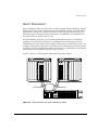
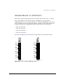
Port-Based VLANs 6-2
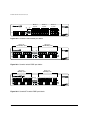
Spanning Switches with Port-Based VLANs
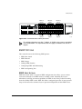
Tagged VLANs 6-6
Uses of Tagged VLANs 6-6
VI
6-3
5-2
5-3
4-9
Assigning a VLAN Tag 6-6
Mixing Port-Based and Tagged VLANs 6-9
Protocol-Based VLANs 6-9
Predefined Protocol Filters 6-10
Defining Protocol Filters 6-11
Deleting a Protocol Filter 6-12
Precedence of Tagged Packets Over Protocol Filters 6-12
VLAN Names 6-12
Default VLAN 6-12
Renaming a VLAN 6-13
Configuring VLANs on the Switch 6-13
VLAN Configuration Commands 6-14
VLAN Configuration Examples 6-15
Displaying VLAN Settings 6-16
Generic VLAN Registration Protocol 6-17
GVRP and Spanning Tree Domains 6-19
GVRP Commands 6-19
MAC-Based VLANs 6-20
MAC-Based VLAN Guidelines 6-21
MAC-Based VLAN Limitations 6-21
MAC-Based VLAN Commands 6-22
MAC-Based VLAN Example 6-22
Timed Configuration Download for MAC-Based VLANs 6-23
Example 6-23
7
FORWARDING DATABASE (FDB)
Overview of the FDB 7-1
FDB Contents 7-1
FDB Entry Types 7-2
How FDB Entries Get Added 7-3
Associating a QoS Profile with an FDB Entry
Configuring FDB Entries 7-3
FDB Configuration Examples 7-4
Displaying FDB Entries 7-5
7-3
VII
8
SPANNING TREE PROTOCOL (STP)
Overview of the Spanning Tree Protocol 8-1
Spanning Tree Domains 8-2
STPD Status for GVRP-Added Ports 8-2
Defaults 8-3
STP Configurations 8-3
Configuring STP on the Switch 8-6
STP Configuration Example 8-8
Displaying STP Settings 8-8
Disabling and Resetting STP 8-9
9
QUALITY
OF
SERVICE (QOS)
Overview of Policy-Based Quality of Service 9-2
Applications and Types of QoS 9-3
Voice Applications 9-3
Video Applications 9-3
Critical Database Applications 9-4
Web Browsing Applications 9-4
File Server Applications 9-4
Assigning QoS Attributes
9-5
QoS Profiles 9-6
Configuring a QoS Profile 9-8
Traffic Groupings and Creating a QoS Policy 9-8
IP-Based Traffic Groupings 9-10
MAC-Based Traffic Groupings 9-10
Permanent MAC addresses 9-10
Dynamic MAC Addresses 9-11
Blackhole MAC Address
9-11
Broadcast/Unknown Rate Limiting MAC Address
Verifying MAC-Based QoS Settings 9-12
Explicit Class of Service (802.1p and DiffServ) Traffic
Groupings 9-12
Configuring 802.1p Priority 9-12
Observing 802.1p Information 9-13
802.1p Commands 9-14
Changing the Default 802.1p Mapping 9-14
Replacing 802.1p Priority Information 9-14
VIII
9-11
Configuring DiffServ 9-15
Observing DiffServ Information 9-17
Changing DiffServ Code point assignments in the Q0S
Profile 9-17
Replacing DiffServ Code Points 9-18
DiffServ Example 9-19
Physical and Logical Groupings 9-20
Source port 9-20
VLAN 9-20
Verifying Physical and Logical Groupings 9-21
Verifying Configuration and Performance 9-21
QoS Monitor 9-21
Real-Time Performance Monitoring 9-22
Background Performance Monitoring 9-22
Displaying QoS Profile Information 9-23
Modifying a QoS Policy 9-23
Intra-Subnet QoS 9-24
Dynamic Link Context System 9-25
DLCS Guidelines 9-25
DLCS Limitations 9-26
DLCS Commands 9-26
10
EXTREME STANDBY ROUTER PROTOCOL
Overview 10-1
ESRP-Aware Switches 10-2
ESRP Basics 10-2
Determining the ESRP Master 10-3
ESRP Tracking 10-4
ESRP VLAN Tracking 10-4
ESRP Route Table Tracking 10-4
ESRP Ping Tracking 10-4
ESRP Election Algorithms 10-5
Master Switch Behavior 10-5
Standby Switch Behavior 10-6
Electing the Master Switch 10-6
Failover Time 10-6
Grouping Blocks of 10/100 Ports 10-7
ESRP Options 10-9
IX
ESRP Host Attach 10-9
ESRP Domains 10-10
ESRP Groups 10-11
Linking ESRP Switches 10-12
Configuring ESRP and Multinetting 10-12
ESRP and Spanning Tree 10-12
ESRP and VLAN aggregation 10-13
ESRP Commands 10-14
ESRP Examples 10-16
Single VLAN Using Layer 2 and Layer 3 Redundancy
Multiple VLANs Using Layer 2 Redundancy 10-18
Displaying ESRP Information 10-20
11
IP UNICAST ROUTING
Overview of IP Unicast Routing 11-2
Router Interfaces 11-2
Populating the Routing Table 11-3
Dynamic Routes 11-4
Static Routes 11-4
Multiple Routes 11-4
IP Route Sharing 11-5
Proxy ARP 11-5
ARP-Incapable Devices 11-5
Proxy ARP Between Subnets 11-6
Relative Route Priorities 11-6
IP Multinetting 11-7
IP Multinetting Operation 11-8
IP Multinetting Examples 11-9
Configuring IP Unicast Routing 11-10
Verifying the IP Unicast Routing Configuration 11-11
VLAN Aggregation 11-11
VLAN Aggregation Properties 11-13
VLAN Aggregation Limitations 11-13
Isolation Option for Communication Between Sub-VLANs
VLAN Aggregation Commands 11-14
VLAN Aggregation Example 11-15
Verifying the VLAN Aggregation Configuration 11-15
X
10-16
11-14
Configuring DHCP/BOOTP Relay 11-16
Verifying the DHCP/BOOTP Relay Configuration
UDP-Forwarding 11-16
Configuring UDP-Forwarding 11-17
UPD-Forwarding Example 11-17
ICMP Packet Processing 11-18
UDP-Forwarding Commands 11-18
IP Commands 11-19
Routing Configuration Example 11-25
Displaying Router Settings 11-27
Resetting and Disabling Router Settings 11-28
12
11-16
INTERIOR GATEWAY ROUTING PROTOCOLS
Overview 12-2
RIP Versus OSPF 12-2
Overview of RIP 12-3
Routing Table 12-3
Split Horizon 12-4
Poison Reverse 12-4
Triggered Updates 12-4
Route Advertisement of VLANs 12-4
RIP Version 1 Versus RIP Version 2 12-5
Overview of OSPF 12-5
Link-State Database 12-5
Areas 12-6
Area 0 12-6
Stub Areas 12-7
Not-So-Stubby-Areas (NSSA) 12-7
Normal Area 12-8
Virtual Links 12-8
Route Re-distribution 12-10
Configuring Route Re-Distribution 12-11
Re-Distributing Routes into OSPF 12-12
Previous Release Issues with OSPF Re-Distribution
Re-Distributing Routes into RIP 12-13
OSPF Timers and Authentication 12-13
Configuring RIP 12-14
12-12
XI
RIP Configuration Example 12-17
Displaying RIP Settings 12-19
Resetting and Disabling RIP 12-20
Configuring OSPF 12-21
OSPF Configuration Example 12-25
Configuration for ABR1 12-27
Configuration for IR1 12-27
Displaying OSPF Settings 12-28
Resetting and Disabling OSPF Settings
13
12-28
EXTERIOR GATEWAY ROUTING PROTOCOLS
Overview 13-2
BGP Attributes 13-2
BGP Communities 13-3
BGP Features 13-3
Route Reflectors 13-3
Route Confederations 13-4
Route Confederation Example 13-4
Route Aggregation 13-8
Using Route Aggregation 13-8
IGP Synchronization 13-9
Using The Loopback Interface 13-9
OSPF to BGP Route Re-Distribution 13-9
Configuring BGP 13-10
Displaying BGP Settings 13-15
Resetting and Disabling BGP 13-15
14
IP MULTICAST ROUTING
Overview 14-2
DVMRP Overview 14-2
PIM Overview 14-2
PIM Dense Mode 14-3
PIM Sparse Mode (PIM-SM) 14-3
IGMP Overview 14-3
IGMP Snooping 14-4
Configuring IP Multicasting Routing 14-4
Configuration Examples 14-9
XII
PIM-DM Configuration Example 14-10
Configuration for IR1 14-11
Configuration for ABR1 14-13
Displaying IP Multicast Routing Settings 14-13
Deleting and Resetting IP Multicast Settings 14-14
15
IPX ROUTING
Overview of IPX 15-1
Router Interfaces 15-1
IPX Routing Performance 15-3
IPX Encapsulation Types 15-3
Populating the Routing Table 15-4
Dynamic Routes 15-4
Static Routes 15-4
IPX/RIP Routing 15-4
GNS Support 15-5
Routing SAP Advertisements 15-5
Configuring IPX 15-6
Verifying IPX Router Configuration 15-6
Protocol-Based VLANs for IPX 15-7
IPX Commands 15-7
IPX Configuration Example 15-11
Displaying IPX Settings 15-13
Resetting and Disabling IPX 15-14
16
ACCESS POLICIES
Overview of Access Policies 16-1
IP Access Lists 16-2
Routing Access Policies 16-2
Route Maps 16-2
Using IP Access Lists 16-2
How IP Access Lists Work 16-3
Precedence Numbers 16-3
Specifying a Default Rule 16-3
The permit-established Keyword 16-4
Adding and Deleting Access List Entries
Maximum Entries 16-5
16-4
XIII
Access Lists for ICMP 16-5
Verifying Access List Configurations 16-6
Access List Commands 16-6
IP Access List Examples 16-11
Using the Permit-Established Keyword 16-11
Example 2: Filter ICMP Packets 16-14
Using Routing Access Policies 16-15
Creating an Access Profile 16-16
Configuring an Access Profile Mode 16-16
Adding an Access Profile Entry 16-17
Specifying Subnet Masks 16-17
Sequence Numbering 16-17
Permit and Deny Entries 16-18
Autonomous System Expressions 16-18
Deleting an Access Profile Entry 16-18
Applying Access Profiles 16-18
Routing Access Policies for RIP 16-19
Examples 16-19
Routing Access Policies for OSPF 16-21
Example 16-22
Routing Access Policies for DVMRP 16-23
Example 16-23
Routing Access Policies for PIM 16-24
Example 16-24
Routing Access Policies for BGP 16-25
Making Changes to a Routing Access Policy 16-25
Removing a Routing Access Policy 16-26
Routing Access Policy Commands 16-26
Using Route Maps 16-29
Creating a Route Map 16-30
Add Entries to the Route Map 16-30
Add Statements to the Route Map Entries 16-30
Route Map Operation 16-32
Route Map Example 16-32
Changes to Route Maps 16-34
Route Maps in BGP 16-34
Route Map Commands 16-35
XIV
17
SERVER LOAD BALANCING (SLB)
Overview 17-2
SLB Components 17-2
Nodes 17-3
Pools 17-3
Virtual Servers 17-3
Using Standard or Wildcard Virtual Servers
Forwarding Modes 17-5
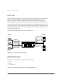
Transparent Mode 17-5
Translational Mode 17-8
Port Translation Mode 17-10
GoGo Mode 17-11
VIP Network Advertisement 17-12
Balancing Methods 17-13
Round-Robin 17-13
Ratio 17-13
Ratio Weight 17-14
Least Connections 17-14
Priority 17-14
Basic SLB Commands 17-15
Advanced SLB Application Example 17-18
Health Checking 17-22
Ping-Check 17-23
Ping-Check Commands 17-23
TCP-Port-Check 17-23
TCP-Port-Check Commands 17-23
Service-Check 17-24
Service-Check Commands 17-25
External Health Checking 17-25
Maintenance Mode 17-25
Persistence 17-26
Client Persistence 17-26
Sticky Persistence 17-26
Using High Availability System Features 17-27
Redundant SLB 17-27
Using Ping-Check 17-28
Configuring Active-Active Operation 17-28
17-4
XV
Sample Active-Active Configuration
Using Manual Fail-Back 17-31
3DNS Support 17-32
Advanced SLB Commands 17-32
Web Cache Redirection 17-38
Flow Redirection 17-38
Flow Redirection Commands 17-39
Flow Redirection Example 17-39
18
STATUS MONITORING
AND
STATISTICS
Status Monitoring 18-1
Slot Diagnostics 18-3
Port Statistics 18-4
Port Errors 18-5
Port Monitoring Display Keys 18-6
Setting the System Recovery Level 18-7
Logging 18-7
Local Logging 18-9
Real-Time Display 18-9
Remote Logging 18-9
Logging Configuration Changes 18-10
Logging Commands 18-11
RMON 18-12
About RMON 18-12
RMON Features of the Switch 18-13
Statistics 18-13
History 18-13
Alarms 18-13
Events 18-14
Configuring RMON 18-14
Event Actions 18-15
19
USING EXTREMEWARE VISTA
Enabling and Disabling Web Access 19-2
Setting Up Your Browser 19-2
Accessing ExtremeWare Vista 19-3
Navigating ExtremeWare Vista 19-4
XVI
17-29
Task Frame 19-4
Content Frame 19-4
Browser Controls 19-5
Status Messages 19-5
Standalone Buttons 19-5
Saving Changes 19-6
Filtering Information 19-6
Do a GET When Configuring a VLAN 19-7
Sending Screen Output to Extreme Networks
20
SOFTWARE UPGRADE
AND
19-7
BOOT OPTIONS
Downloading a New Image 20-1
Rebooting the Switch 20-2
Saving Configuration Changes 20-3
Returning to Factory Defaults 20-3
Using TFTP to Upload the Configuration 20-4
Using TFTP to Download the Configuration 20-5
Downloading a Complete Configuration 20-5
Downloading an Incremental Configuration 20-5
Scheduled Incremental Configuration Download 20-6
Remember to Save 20-6
Synchronizing MSMs 20-7
Upgrading and Accessing BootROM 20-7
Upgrading BootROM 20-7
Accessing the BootROM menu 20-7
Boot Option Commands 20-8
A
SUPPORTED STANDARDS
B
TROUBLESHOOTING
LEDs B-1
Using the Command-Line Interface
Port Configuration B-5
VLANs B-6
STP B-7
Debug Tracing B-8
B-3
XVII
TOP Command B-8
Contacting Extreme Technical Support
INDEX
INDEX
XVIII
OF
COMMANDS
B-8
Preface
This Preface provides an overview of this guide, describes guide conventions, and lists
other publications that may be useful.
INTRODUCTION
This guide provides the required information to configure ExtremeWare™ software
running on a BlackDiamond™, Alpine™, or Summit™ switch.
This guide is intended for use by network administrators who are responsible for
installing and setting up network equipment. It assumes a basic working knowledge of
the following:
• Local area networks (LANs)
• Ethernet concepts
• Ethernet switching and bridging concepts
• Routing concepts
• Internet Protocol (IP) concepts
• Routing Information Protocol (RIP) and Open Shortest Path First (OSPF) concepts
• Border Gateway Protocol (BGP-4) concepts
• IP Multicast concepts
• Distance Vector Multicast Routing Protocol (DVMRP) concepts
• Protocol Independent Multicast (PIM) concepts
EXTREMEWARE SOFTWARE USER GUIDE
XIX
PREFACE
• Internet Packet Exchange (IPX) concepts
• Server Load Balancing (SLB) concepts
• Simple Network Management Protocol (SNMP)
If the information in the “Release Notes” shipped with your switch differs from the
information in this guide, follow the “Release Notes.”
TERMINOLOGY
When features, functionality, or operation is specific to the Summit, Alpine, or
BlackDiamond switch family, the family name is used. Explanations about features and
operations that are the same across all switch product families simply refer to the
product as the “switch.”
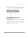
CONVENTIONS
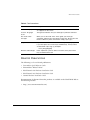
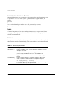
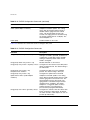
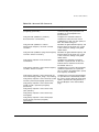
Table 1 and Table 2 list conventions that are used throughout this guide.
Table 1: Notice Icons
Icon
XX
Notice Type
Alerts you to...
Note
Important features or instructions.
Caution
Risk of personal injury, system damage,
or loss of data.
Warning
Risk of severe personal injury.
EXTREMEWARE SOFTWARE USER GUIDE
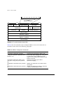
RELATED PUBLICATIONS
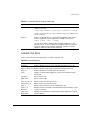
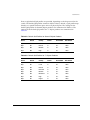
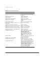
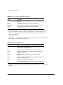
Table 2: Text Conventions
Convention
Description
Screen displays
This typeface indicates command syntax, or represents information
as it appears on the screen.
Screen displays
bold
This typeface indicates how you would type a particular command.
The words “enter”
and “type”
When you see the word “enter” in this guide, you must type
something, and then press the Return or Enter key. Do not press the
Return or Enter key when an instruction simply says “type.”
[Key] names
Key names are written with brackets, such as [Return] or [Esc].
If you must press two or more keys simultaneously, the key names
are linked with a plus sign (+). Example:
Press [Ctrl]+[Alt]+[Del].
Words in italicized type
Italics emphasize a point or denote new terms at the place where
they are defined in the text.
RELATED PUBLICATIONS
The following is a list of related publications:
• ExtremeWare Quick Reference Guide
• ExtremeWare “Release Notes”
• BlackDiamond 6800 Hardware Installation Guide
• BlackDiamond 3800 Hardware Installation Guide
• Summit Hardware Installation Guide
Documentation for Extreme Networks products is available on the World Wide Web at
the following location:
• http://www.extremenetworks.com/
EXTREMEWARE SOFTWARE USER GUIDE
XXI
PREFACE
XXII
EXTREMEWARE SOFTWARE USER GUIDE
1
ExtremeWare Overview
This chapter covers the following topics:
• Summary of Features on page 1-1
• “i” Chipset Products on page 1-5
• Software Licensing on page 1-6
• Software Factory Defaults on page 1-8
ExtremeWare is the full-featured software operating system that is designed to run on
the BlackDiamond, Alpine, and Summit families of Gigabit Ethernet switches.
SUMMARY
OF
FEATURES
The features of ExtremeWare include the following:
• Virtual local area networks (VLANs) including support for IEEE 802.1Q and IEEE
802.1p
• VLAN aggregation
• Spanning Tree Protocol (STP) (IEEE 802.1D) with multiple STP domains
• Policy-Based Quality of Service (PB-QoS)
• Wire-speed Internet Protocol (IP) routing
• IP Multinetting
• DHCP/BOOTP Relay
EXTREMEWARE SOFTWARE USER GUIDE
1-1
EXTREMEWARE OVERVIEW
• Extreme Standby Router Protocol (ESRP)
• Routing Information Protocol (RIP) version 1 and RIP version 2
• Open Shortest Path First (OSPF) routing protocol
• Border Gateway Protocol (BGP) version 4
• Wire-speed IP multicast routing support
• Diffserv support
• Access-policy support for routing protocols
• Access list support for packet filtering
• IGMP snooping to control IP multicast traffic
• Distance Vector Multicast Routing Protocol (DVMRP)
• Protocol Independent Multicast-Dense Mode (PIM-DM)
• Protocol Independent Multicast-Sparse Mode (PIM-SM)
• Wire-speed IPX, IPX/RIP, and IPX/SAP support
• Server Load Balancing (SLB) support
• Load sharing on multiple ports, across all blades (BlackDiamond only)
• RADIUS client and per-command authentication support
• TACACS+ support
• Console command-line interface (CLI) connection
• Telnet CLI connection
• SSH2 connection
• ExtremeWare Vista Web-based management interface
• Simple Network Management Protocol (SNMP) support
• Remote Monitoring (RMON)
• Traffic mirroring for all ports, across all blades (BlackDiamond only)
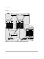
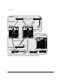
For more information on BlackDiamond 6808 switch components, refer to the
BlackDiamond 6800 Switch Hardware Installation Guide. For more information
on Alpine 3800 switch components, refer to the Alpine 3800 Switch Hardware
Installation Guide. For more information on Summit switch components, refer to
the Summit Hardware Installation Guide.
1-2
EXTREMEWARE SOFTWARE USER GUIDE
SUMMARY
OF
FEATURES
VIRTUAL LANS (VLANS)
ExtremeWare has a VLAN feature that enables you to construct your broadcast domains
without being restricted by physical connections. A VLAN is a group of location- and
topology-independent devices that communicate as if they were on the same physical
local area network (LAN).
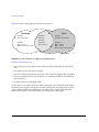
Implementing VLANs on your network has the following three advantages:
• They help to control broadcast traffic. If a device in VLAN Marketing transmits a
broadcast frame, only VLAN Marketing devices receive the frame.
• They provide extra security. Devices in VLAN Marketing can only communicate with
devices on VLAN Sales using routing services.
• They ease the change and movement of devices on networks.
For more information on VLANs, refer to Chapter 6.
SPANNING TREE PROTOCOL
The switch supports the IEEE 802.1D Spanning Tree Protocol (STP), which is a
bridge-based mechanism for providing fault tolerance on networks. STP enables you to
implement parallel paths for network traffic, and ensure the following:
• Redundant paths are disabled when the main paths are operational.
• Redundant paths are enabled if the main traffic paths fail.
A single spanning tree can span multiple VLANs.
For more information on STP, refer to Chapter 8.
QUALITY
OF
SERVICE
ExtremeWare has Policy-Based Quality of Service (QoS) features that enable you to
specify service levels for different traffic groups. By default, all traffic is assigned the
“normal” QoS policy profile. If needed, you can create other QoS policies and apply
them to different traffic types so that they have different guaranteed minimum
bandwidth, maximum bandwidth, and priority.
EXTREMEWARE SOFTWARE USER GUIDE
1-3
EXTREMEWARE OVERVIEW
For more information on Quality of Service, refer to Chapter 9.
UNICAST ROUTING
The switch can route IP or IPX traffic between the VLANs that are configured as virtual
router interfaces. Both dynamic and static IP routes are maintained in the routing table.
The following routing protocols are supported:
• RIP version 1
• RIP version 2
• OSPF
• IPX/RIP
• BGP version 4
For more information on IP unicast routing, refer to Chapter 11. For more
information on IPX/RIP, refer to Chapter 15.
IP MULTICAST ROUTING
The switch can use IP multicasting to allow a single IP host to transmit a packet to a
group of IP hosts. ExtremeWare supports multicast routes that are learned by way of the
Distance Vector Multicast Routing Protocol (DVMRP) or the Protocol Independent
Multicast (dense mode or sparse mode).
For more information on IP multicast routing, refer to Chapter 14.
LOAD SHARING
Load sharing allows you to increase bandwidth and resiliency by using a group of ports
to carry traffic in parallel between systems. The sharing algorithm allows the switch to
use multiple ports as a single logical port. For example, VLANs see the load-sharing
group as a single virtual port. The algorithm also guarantees packet sequencing
between clients.
1-4
EXTREMEWARE SOFTWARE USER GUIDE
“I” CHIPSET PRODUCTS
For information on load sharing, refer to Chapter 4 and Chapter 5.
“i” CHIPSET PRODUCTS
Summit switches and BlackDiamond 6800 switch modules that use naming conventions
ending with an “i” have additional capabilities that are documented throughout this
User Guide. For the most current list of products supporting the “i” chipset, consult
your Release Notes.
Unless otherwise specified, a feature requiring the “i” chipset requires the use of the
BlackDiamond MSM64i and an “i” chipset-based I/O module, such as the G8Xi.
“i” CHIPSET FEATURE DIFFERENCES
The following list summarizes the feature areas specific to the “i” chipset products:
• QoS and Access Policies – Complete use of IP access lists (products without the “i”
chipset are capable of a subset of this functionality); support for IP DiffServ; and
support for eight QoS queues per port, instead of four.
• Bridging/Switching – Support for jumbo frames; support for address- and
round-robin-based load-sharing algorithms; ports belonging to a load-sharing group
do not need to be contiguous.
• Routing – Wire-speed IPX routing
• BGP-4 – Requires the use of the “i” chipset, but requires only the MSM64i on the
BlackDiamond.
• Server Load Balancing – Requires the use of the “i” chipset.
• Web cache redirection – Requires the use of the “i” chipset.
• ESRP – No port blocking restrictions, use of the additional tracking ESRP feature.
• Load sharing – No contiguous port restrictions.
EXTREMEWARE SOFTWARE USER GUIDE
1-5
EXTREMEWARE OVERVIEW
SOFTWARE LICENSING
Some Extreme Networks products have capabilities that are enabled by using a license
key. Keys are typically unique to the switch, and are not transferable. Keys are stored in
NVRAM and, once entered, persist through reboots, software upgrades, and
reconfigurations. The following sections describe the features that are associated with
license keys.
ROUTER LICENSING
Some switches support software licensing for different levels of router functionality. In
ExtremeWare version 6.0 and above, routing protocol support is separated into two sets:
Basic and Full L3. Basic is a subset of Full L3.
BASIC FUNCTIONALITY
Basic functionality requires no license key. All Extreme switches have Basic layer 3
functionality, without the requirement of a license key. Basic functionality includes all
switching functions, and also includes all available layer 3 QoS, access list, and ESRP
functions. Layer 3 routing functions include support for the following:
• IP routing using RIP version 1 and/or RIP version 2
• IP routing between directly attached VLANs
• IP routing using static routes
FULL L3 FUNCTIONALITY
On switches that support router licensing, the Full L3 license enables support of
additional routing protocols and functions, including the following:
• IP routing using OSPF
• IP multicast routing using DVMRP
• IP multicast routing using PIM (Dense Mode or Sparse Mode)
• IPX routing (direct, static, and dynamic using IPX/RIP and IPX/SAP)
• IP routing using BGP
• Server load balancing
• Web cache redirection
1-6
EXTREMEWARE SOFTWARE USER GUIDE
SOFTWARE LICENSING
PRODUCT SUPPORT
ExtremeWare version 6.0 and above supports router licensing on the Summit24 switch,
Summit48 switch, and Summit7i switch. The BlackDiamond 6808 switch supports all
documented router functions, without the need for additional router licensing. Consult
the Release Notes for the most current set of products that require router licensing
support.
VERIFYING
THE
ROUTER LICENSE
To verify the router license, use the show switch command.
OBTAINING
A
ROUTER LICENSE
You can order the desired functionality from the factory, using the appropriate model of
the desired product. If you order licensing from the factory, the switch arrives packaged
with a certificate that contains the unique license key(s), and instructions for enabling
the correct functionality on the switch. The certificate is typically packaged with the
switch documentation. Once the license key is entered, it should not be necessary to
enter the information again. However, we recommend keeping the certificate for your
records.
You may upgrade the router licensing of an existing product by purchasing a voucher
for the desired product and functionality. Please contact your supplier to purchase a
voucher.
Once received, the voucher contains information and instructions on obtaining a license
key for the switch using the Extreme Networks Support website at:
http://www.extremenetworks.com/extreme/support/upgrade.htm
or by phoning Extreme Networks Technical Support at:
• (800) 998-2408
• (408) 579-2826
SECURITY LICENSING
Certain additional ExtremeWare security features, such as the use of Secure Shell (SSH2)
encryption, may be under United States export restriction control. Extreme Networks
ships these security features in a disabled state, and you may obtain a Security License
Key at no charge from Extreme Networks to enable the features.
EXTREMEWARE SOFTWARE USER GUIDE
1-7
EXTREMEWARE OVERVIEW
OBTAINING
A
SECURITY LICENSE
To obtain information on enabling features that require export restriction, access the
Extreme Networks Support website at:
http://www.extremenetworks.com/go/security.htm
Fill out a contact form to indicate compliance or non-compliance with the export
restrictions. If you are in compliance, you will be given information that will allow you
to enable security features.
SECURITY FEATURES UNDER LICENSE CONTROL
ExtremeWare version 6.0 and above supports the SSH2 protocol. SSH2 allows the
encryption of Telnet session data. The encryption methods used are under U.S. export
restriction control.
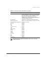
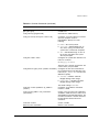
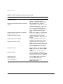
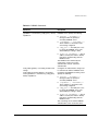
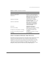
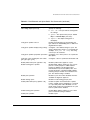
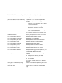
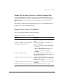
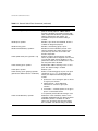
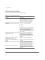
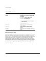
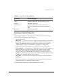
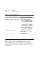
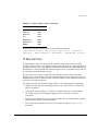
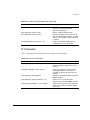
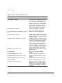
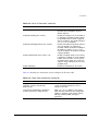
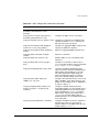
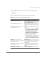
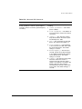
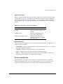
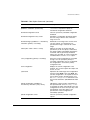
SOFTWARE FACTORY DEFAULTS
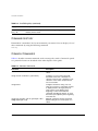
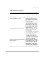
Table 1-1 shows factory defaults for global ExtremeWare features.
Table 1-1: ExtremeWare Global Factory Defaults
Item
Default Setting
Serial or Telnet user account
admin with no password and user with no password
Web network management
Enabled
Telnet
Enabled
SSH2
Disabled
SNMP
Enabled
SNMP read community string
public
SNMP write community string
private
RMON
Disabled
BOOTP
Enabled on the default VLAN (default)
QoS
All traffic is part of the default queue
QoS monitoring
Automatic roving
802.1p priority
Recognition enabled
802.3x flow control
Enabled on Gigabit Ethernet ports
1-8
EXTREMEWARE SOFTWARE USER GUIDE
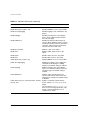
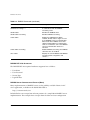
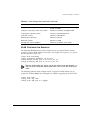
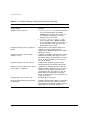
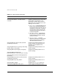
SOFTWARE FACTORY DEFAULTS
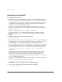
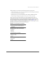
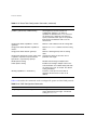
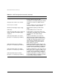
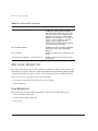
Table 1-1: ExtremeWare Global Factory Defaults (continued)
Item
Default Setting
Virtual LANs
Three VLANs pre-defined. VLAN named default contains
all ports and belongs to the STPD named s0. VLAN mgmt
exists only on switches that have an Ethernet management
port, and contains only that port. The Ethernet
management port is DTE only, and is not capable of
switching or routing. VLAN MacVLanDiscover is used only
when using the MAC VLAN feature.
802.1Q tagging
All packets are untagged on the default VLAN (default)
Spanning Tree Protocol
Disabled for the switch; enabled for each port in the STPD
Forwarding database aging period
300 seconds (5 minutes)
IP Routing
Disabled
RIP
Disabled
OSPF
Disabled
IP multicast routing
Disabled
IGMP
Enabled
IGMP snooping
Enabled
DVMRP
Disabled
GVRP
Disabled
PIM-DM
Disabled
IPX routing
Disabled
NTP
Disabled
DNS
Disabled
Port mirroring
Disabled
For default settings of individual ExtremeWare features, refer to individual
chapters in this guide.
EXTREMEWARE SOFTWARE USER GUIDE
1-9
EXTREMEWARE OVERVIEW
1-10
EXTREMEWARE SOFTWARE USER GUIDE
2
Accessing the Switch
This chapter covers the following topics:
• Understanding the Command Syntax on page 2-1
• Line-Editing Keys on page 2-5
• Command History on page 2-6
• Common Commands on page 2-6
• Configuring Management Access on page 2-9
• Domain Name Service Client Services on page 2-13
• Checking Basic Connectivity on page 2-13
UNDERSTANDING
THE
COMMAND SYNTAX
This section describes the steps to take when entering a command. Refer to the sections
that follow for detailed information on using the command-line interface.
When entering a command at the prompt, ensure that you have the appropriate
privilege level. Most configuration commands require you to have the administrator
privilege level. To use the command-line interface (CLI), follow these steps:
1 Enter the command name.
If the command does not include a parameter or values, skip to Step 3. If the
command requires more information, continue to Step 2.
2 If the command includes a parameter, enter the parameter name and values.
EXTREMEWARE SOFTWARE USER GUIDE
2-1
ACCESSING
THE
SWITCH
3 The value part of the command specifies how you want the parameter to be set.
Values include numerics, strings, or addresses, depending on the parameter.
4 After entering the complete command, press [Return].
If an asterisk (*) appears in front of the command-line prompt, it indicates that
you have outstanding configuration changes that have not been saved. For more
information on saving configuration changes, refer to Chapter 20.
SYNTAX HELPER
The CLI has a built-in syntax helper. If you are unsure of the complete syntax for a
particular command, enter as much of the command as possible and press [Return]. The
syntax helper provides a list of options for the remainder of the command.
The syntax helper also provides assistance if you have entered an incorrect command.
COMMAND COMPLETION
WITH
SYNTAX HELPER
ExtremeWare provides command completion by way of the [Tab] key. If you enter a
partial command, pressing the [Tab] key posts a list of available options, and places the
cursor at the end of the command.
ABBREVIATED SYNTAX
Abbreviated syntax is the most unambiguous, shortest allowable abbreviation of a
command or parameter. Typically, this is the first three letters of the command.
When using abbreviated syntax, you must enter enough characters to make the
command unambiguous and distinguishable to the switch.
COMMAND SHORTCUTS
All named components of the switch configuration must have a unique name.
Components are named using the create command. When you enter a command to
configure a named component, you do not need to use the keyword of the component.
For example, to create a VLAN, you must enter a unique VLAN name:
create vlan engineering
2-2
EXTREMEWARE SOFTWARE USER GUIDE
UNDERSTANDING
THE
COMMAND SYNTAX
Once you have created the VLAN with a unique name, you can then eliminate the
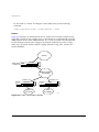
keyword vlan from all other commands that require the name to be entered. For
example, instead of entering the BlackDiamond switch command
config vlan engineering delete port 1:3,4:6
you could enter the following shortcut:
config engineering delete port 1:3,4:6
Similarly, on the Summit switch, instead of entering the command
config vlan engineering delete port 1-3,6
you could enter the following shortcut:
config engineering delete port 1-3,6
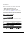
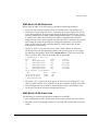
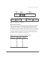
BLACKDIAMOND
AND
ALPINE SWITCH NUMERICAL RANGES
Commands that require you to enter one or more port numbers on a BlackDiamond and
Alpine switch use the parameter <portlist> in the syntax. A <portlist> can be one
port on a particular slot. For example,
port 3:1
A <portlist> can be a range of numbers. For example,
port 3:1-3:3
You can add additional slot and port numbers to the list, separated by a comma:
port 3:1,4:8,6:10
You can specify all ports on a particular slot. For example,
port 3:*
indicates all ports on slot 3.
You can specify a range of slots and ports. For example,
port 2:3-4:5
indicates slot 2, port 3 through slot 4, port 5.
EXTREMEWARE SOFTWARE USER GUIDE
2-3
ACCESSING
THE
SWITCH
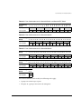
SUMMIT SWITCH NUMERICAL RANGES
Commands that require you to enter one or more port numbers on a Summit switch use
the parameter <portlist> in the syntax. A portlist can be a range of numbers, for
example:
port 1-3
You can add additional port numbers to the list, separated by a comma:
port 1-3,6,8
NAMES
All named components of the switch configuration must have a unique name. Names
must begin with an alphabetical character and are delimited by whitespace, unless
enclosed in quotation marks.
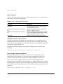
SYMBOLS
You may see a variety of symbols shown as part of the command syntax. These symbols
explain how to enter the command, and you do not type them as part of the command
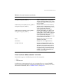
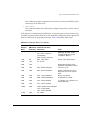
itself. Table 2-1 summarizes command syntax symbols.
Table 2-1: Command Syntax Symbols
Symbol
Description
angle brackets < >
Enclose a variable or value. You must specify the variable or value. For
example, in the syntax
config vlan <name> ipaddress <ip_address>
you must supply a VLAN name for <name> and an address for
<ip_address> when entering the command. Do not type the angle
brackets.
square brackets [ ]
Enclose a required value or list of required arguments. One or more
values or arguments can be specified. For example, in the syntax
use image [primary | secondary]
you must specify either the primary or secondary image when entering
the command. Do not type the square brackets.
2-4
EXTREMEWARE SOFTWARE USER GUIDE
LINE-EDITING KEYS
Table 2-1: Command Syntax Symbols (continued)
Symbol
Description
vertical bar |
Separates mutually exclusive items in a list, one of which must be entered. For
example, in the syntax
config snmp community [read-only | read-write] <string>
you must specify either the read or write community string in the command. Do not
type the vertical bar.
braces { }
Enclose an optional value or a list of optional arguments. One or more
values or arguments can be specified. For example, in the syntax
reboot {<date> <time> | cancel}
you can specify either a particular date and time combination, or the
keyword cancel to cancel a previously scheduled reboot. If you do not
specify an argument, the command will prompt, asking if you want to
reboot the switch now. Do not type the braces.
LINE-EDITING KEYS
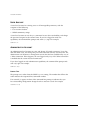
Table 2-2 describes the line-editing keys available using the CLI.
Table 2-2: Line-Editing Keys
Key(s)
Description
Backspace
Deletes character to left of cursor and shifts remainder of line to left.
Delete or [Ctrl] + D
Deletes character under cursor and shifts remainder of line to left.
[Ctrl] + K
Deletes characters from under cursor to end of line.
Insert
Toggles on and off. When toggled on, inserts text and shifts previous
text to right.
Left Arrow
Moves cursor to left.
Right Arrow
Moves cursor to right.
Home or [Ctrl] + A
Moves cursor to first character in line.
End or [Ctrl] + E
Moves cursor to last character in line.
[Ctrl] + L
Clears screen and movers cursor to beginning of line.
[Ctrl] + P or
Up Arrow
Displays previous command in command history buffer and places cursor
at end of command.
[Ctrl] + N or
Down Arrow
Displays next command in command history buffer and places cursor at
end of command.
EXTREMEWARE SOFTWARE USER GUIDE
2-5
ACCESSING
THE
SWITCH
Table 2-2: Line-Editing Keys (continued)
Key(s)
Description
[Ctrl] + U
Clears all characters typed from cursor to beginning of line.
[Ctrl] + W
Deletes previous word.
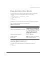
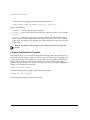
COMMAND HISTORY
ExtremeWare “remembers” the last 49 commands you entered. You can display a list of
these commands by using the following command:
history
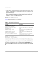
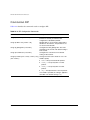
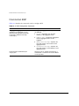
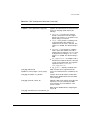
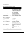
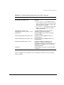
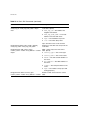
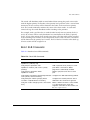
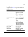
COMMON COMMANDS
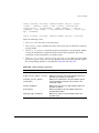
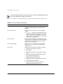
Table 2-3 describes common commands used to manage the switch. Commands specific
to a particular feature are described in the other chapters of this guide.
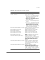
Table 2-3: Common Commands
Command
Description
clear session <number>
Terminates a Telnet session from the
switch.
config account <username> {<password>}
Configures a user account password.
Passwords must have a minimum of 1
character and can have a maximum of 32
characters. User names and passwords
are case-sensitive.
config banner
Configures the banner string. You can
enter up to 24 rows of 79-column text that
is displayed before the login prompt of
each session. Press [Return] at the
beginning of a line to terminate the
command and apply the banner. To clear
the banner, press [Return] at the beginning
of the first line.
config ports <portlist> auto off {speed [10 | 100 |
1000]} duplex [half | full]
Manually configures the port speed and
duplex setting of one or more ports on a
switch.
2-6
EXTREMEWARE SOFTWARE USER GUIDE
COMMON COMMANDS
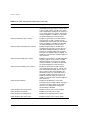
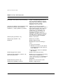
Table 2-3: Common Commands (continued)
Command
Description
config slot <slot> module [f32t | f32f | f48t | g4x |
g6x | g8x | g12x]
Configures a slot for a particular I/O
module card.
config ssh2 key {pregenerated}
Generates the SSH2 host key.
config sys-recovery-level [none | critical | all]
Configures a recovery option for instances
where an exception occurs in
ExtremeWare. Specify one of the
following:
config time <date> <time>
■
none — No recovery mode.
■
critical — ExtremeWare logs an
error to the syslog, and reboots the
system after a critical task exceptions
■
all — ExtremeWare logs an error to
the syslog, and reboots the system
after any exception.
Configures the system date and time. The
format is as follows:
mm/dd/yyyy hh:mm:ss
The time uses a 24-hour clock format. You
cannot set the year past 2036.
config timezone <gmt_offset> {autodst | noautodst}
Configures the time zone information to
the configured offset from GMT time. The
format of gmt_offset is +/- minutes from
GMT time. Specify:
■
autodst — Enables automatic
Daylight Savings Time change.
■
nosautodst — Disables automatic
Daylight Savings Time change.
The default setting is autodst.
config vlan <name> ipaddress <ip_address>
{<mask>}
Configures an IP address and subnet
mask for a VLAN.
create account [admin | user] <username>
{<password>}
Creates a user account. This command is
available to admin-level users and to users
with RADIUS command authorization. The
username is between 1 and 32 characters,
the password is between 0 and 16
characters.
create vlan <name>
Creates a VLAN.
delete account <username>
Deletes a user account.
EXTREMEWARE SOFTWARE USER GUIDE
2-7
ACCESSING
THE
SWITCH
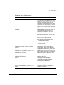
Table 2-3: Common Commands (continued)
Command
Description
delete vlan <name>
Deletes a VLAN.
disable bootp vlan [<name> | all]
Disables BOOTP for one or more VLANs.
disable cli-config-logging
Disables logging of CLI commands to the
Syslog.
disable clipaging
Disables pausing of the screen display
when a show command output reaches
the end of the page.
disable idletimeout
Disables the timer that disconnects all
sessions. Once disabled, console sessions
remain open until the switch is rebooted or
you logoff. Telnet sessions remain open
until you close the Telnet client.
disable port <portlist>
Disables a port on the switch.
disable ssh2
Disables SSH2 Telnet access to the
switch.
disable telnet
Disables Telnet access to the switch.
disable web
Disables Web access to the switch.
enable bootp vlan [<name> | all]
Enables BOOTP for one or more VLANs.
enable cli-config-logging
Enables the logging of CLI configuration
commands to the Syslog for auditing
purposes. The default setting is enabled.
enable clipaging
Enables pausing of the screen display
when show command output reaches the
end of the page. The default setting is
enabled.
enable idletimeout
Enables a timer that disconnects all
sessions (both Telnet and console) after
20 minutes of inactivity. The default setting
is disabled.
enable license [full_L3 | service-provider | security]
<license_key>
Enables a particular software feature
license. Specify <license_key> as an
integer.
The command unconfig switch all
does not clear licensing information. This
license cannot be disabled once it is
enabled on the switch.
2-8
EXTREMEWARE SOFTWARE USER GUIDE
CONFIGURING MANAGEMENT ACCESS
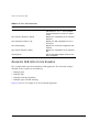
Table 2-3: Common Commands (continued)
Command
Description
enable ssh2 {access-profile [<access_profile> |
none]} {port <tcp_port_number>}
Enables SSH2 Telnet sessions. By default,
SSH2 is enabled with no access profile,
and uses TCP port number 22. To cancel
a previously configured access-profile, use
the none option.
enable telnet {access-profile [<access_profile> |
none]} {port <tcp_port_number>}
Enables Telnet access to the switch. By
default, Telnet is enabled with no access
profile, and uses TCP port number 23. To
cancel a previously configured
access-profile, use the none option.
enable web {access-profile [<access_profile> |
none]} {port <tcp_port_number>}
Enables ExtremeWare Vista Web access
to the switch. By default, Web access is
enabled with no access profile, using TCP
port number 80. Use the none option to
cancel a previously configured
access-profile. You must reboot the switch
for this command to take effect.
history
Displays the previous 49 commands
entered on the switch.
show banner
Displays the user-configured banner.
unconfig switch {all}
Resets all switch parameters (with the
exception of defined user accounts, and
date and time information) to the factory
defaults. If you specify the keyword all,
the switch erases the currently selected
configuration image in flash memory and
reboots. As a result, all parameters are
reset to default settings.
CONFIGURING MANAGEMENT ACCESS
ExtremeWare supports the following two levels of management:
• User
• Administrator
In addition to the management levels, you can optionally use an external RADIUS
server to provide CLI command authorization checking for each command. For more
information on RADIUS, refer to “RADIUS Client,” in Chapter 3.
EXTREMEWARE SOFTWARE USER GUIDE
2-9
ACCESSING
THE
SWITCH
USER ACCOUNT
A user-level account has viewing access to all manageable parameters, with the
exception of the following:
• User account database
• SNMP community strings
A user-level account can use the ping command to test device reachability, and change
the password assigned to the account name. If you have logged on with user
capabilities, the command-line prompt ends with a (>) sign. For example:
Summit1:2>
ADMINISTRATOR ACCOUNT
An administrator-level account can view and change all switch parameters. It can also
add and delete users, and change the password associated with any account name. The
administrator can disconnect a management session that has been established by way of
a Telnet connection. If this happens, the user logged on by way of the Telnet connection
is notified that the session has been terminated.
If you have logged on with administrator capabilities, the command-line prompt ends
with a (#) sign. For example:
Summit1:18#
PROMPT TEXT
The prompt text is taken from the SNMP sysname setting. The number that follows the
colon indicates the sequential line/command number.
If an asterisk (*) appears in front of the command-line prompt, it indicates that you
have outstanding configuration changes that have not been saved. For example:
*Summit1:19#
2-10
EXTREMEWARE SOFTWARE USER GUIDE
CONFIGURING MANAGEMENT ACCESS
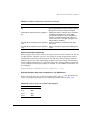
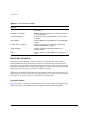
DEFAULT ACCOUNTS
By default, the switch is configured with two accounts, as shown in Table 2-4.
Table 2-4: Default Accounts
Account Name
Access Level
admin
This user can access and change all manageable
parameters. The admin account cannot be deleted.
user
This user can view (but not change) all manageable
parameters, with the following exceptions:
CHANGING
THE
■
This user cannot view the user account database.
■
This user cannot view the SNMP community strings.
DEFAULT PASSWORD
Default accounts do not have passwords assigned to them. Passwords must have a
minimum of 4 characters and can have a maximum of 12 characters.
User names and passwords are case-sensitive.
To add a password to the default admin account, follow these steps:
1 Log in to the switch using the name admin.
2 At the password prompt, press [Return].
3 Add a default admin password by entering the following:
config account admin
4 Enter the new password at the prompt.
5 Re-enter the new password at the prompt.
To add a password to the default user account, follow these steps:
1 Log in to the switch using the name admin.
2 At the password prompt, press [Return], or enter the password that you have
configured for the admin account.
3 Add a default user password by entering the following:
config account user
4 Enter the new password at the prompt.
EXTREMEWARE SOFTWARE USER GUIDE
2-11
ACCESSING
THE
SWITCH
5 Re-enter the new password at the prompt.
If you forget your password while logged out of the command-line interface,
contact your local technical support representative, who will advise on your next
course of action.
CREATING
A
MANAGEMENT ACCOUNT
The switch can have a total of 16 management accounts. You can use the default names
(admin and user), or you can create new names and passwords for the accounts.
Passwords can have a minimum of 0 characters and can have a maximum of 31
characters.
To create a new account, follow these steps:
1 Log in to the switch as admin.
2 At the password prompt, press [Return], or enter the password that you have
configured for the admin account.
3 Add a new user by using the following command:
create account [admin | user] <username>
4 Enter the password at the prompt.
5 Re-enter the password at the prompt.
VIEWING ACCOUNTS
To view the accounts that have been created, you must have administrator privileges.
Use the following command to see the accounts:
show accounts
DELETING
AN
ACCOUNT
To delete a account, you must have administrator privileges. Use the following
command to delete an account:
delete account <username>
The account name admin cannot be deleted.
2-12
EXTREMEWARE SOFTWARE USER GUIDE
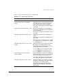
DOMAIN NAME SERVICE CLIENT SERVICES
DOMAIN NAME SERVICE CLIENT SERVICES
The Domain Name Service (DNS) client in ExtremeWare augments the following
commands to allow them to accept either IP addresses or host names:
•
telnet
•
download [bootrom | configuration | image]
•
upload configuration
•
ping
•
traceroute
In addition, the nslookup utility can be used to return the IP address of a hostname.
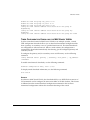
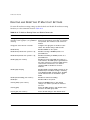
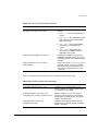
Table 2-5 describes the commands used to configure DNS.
Table 2-5: DNS Commands
Command
Description
config dns-client add <ipaddress>
Adds a DNS name server(s) to the
available server list for the DNS client. Up
to three name servers can be configured.
config dns-client default-domain <domain_name>
Configures the domain that the DNS client
uses if a fully qualified domain name is not
entered. For example, if the default
domain is configured to be foo.com,
executing ping bar searches for
bar.foo.com.
config dns-client delete <ipaddress>
Removes a DNS server.
nslookup <hostname>
Displays the IP address of the requested
host.
show dns-client
Displays the DNS configuration.
CHECKING BASIC CONNECTIVITY
The switch offers the following commands for checking basic connectivity:
• ping
• traceroute
EXTREMEWARE SOFTWARE USER GUIDE
2-13
ACCESSING
THE
SWITCH
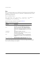
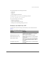
PING
The ping command enables you to send Internet Control Message Protocol (ICMP) echo
messages to a remote IP device. The ping command is available for both the user and
administrator privilege level.
The ping command syntax is
ping {continuous} {size <start_size> {- <end_size>}} [<ip_address> |
<hostname>] {from <src_address> | with record-route | from
<src_ipaddress> with record-route}
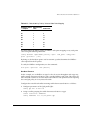
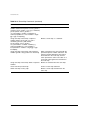
Options for the ping command are described in Table 2-6.
Table 2-6: Ping Command Parameters
Parameter
Description
continuous
Specifies ICMP echo messages to be sent continuously.
This option can be interrupted by pressing any key.
size
Specifies the size of the ICMP request. If both the
start_size and end_size are specified, transmits
ICMP requests using 1 byte increments, per packet. If
no end_size is specified, packets of start_size are
sent.
<ipaddress>
Specifies the IP address of the host.
<hostname>
Specifies the name of the host. To use the hostname,
you must first configure DNS.
from
Uses the specified source address in the ICMP packet.
If not specified, the address of the transmitting interface
is used.
with record-route
Decodes the list of recorded routes and displays them
when the ICMP echo reply is received.
If a ping request fails, the switch continues to send ping messages until interrupted.
Press any key to interrupt a ping request.
2-14
EXTREMEWARE SOFTWARE USER GUIDE
CHECKING BASIC CONNECTIVITY
TRACEROUTE
The traceroute command enables you to trace the routed path between the switch and
a destination endstation. The traceroute command syntax is
traceroute [<ip_address> | <hostname>] {from <src_ipaddress>} {ttl
<TTL>} {port <port>}
where:
• ip_address is the IP address of the destination endstation.
• hostname is the hostname of the destination endstation. To use the hostname, you
must first configure DNS.
• from uses the specified source address in the ICMP packet. If not specified, the
address of the transmitting interface is used.
• ttl configures the switch to trace up to the time-to-live number of the switch.
• port uses the specified UDP port number.
EXTREMEWARE SOFTWARE USER GUIDE
2-15
ACCESSING
2-16
THE
SWITCH
EXTREMEWARE SOFTWARE USER GUIDE
3
Managing the Switch
This chapter covers the following topics:
• Overview on page 3-1
• Using the Console Interface on page 3-2
• Using Telnet on page 3-3
• Using Secure Shell 2 (SSH2) on page 3-7
• Using ExtremeWare Vista on page 3-8
• Using SNMP on page 3-10
• Authenticating Users on page 3-13
• Using the Simple Network Time Protocol on page 3-21
OVERVIEW
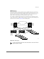
Using ExtremeWare, you can manage the switch using the following methods:
• Access the CLI by connecting a terminal (or workstation with terminal-emulation
software) to the console port.
• Access the switch remotely using TCP/IP through one of the switch ports or
through the dedicated 10/100 unshielded twisted pair (UTP) Ethernet management
port (on switches that are so equipped). Remote access includes the following:
— Telnet using the CLI interface
— SSH2 using the CLI interface
EXTREMEWARE SOFTWARE USER GUIDE
3-1
MANAGING
THE
SWITCH
— ExtremeWare Vista Web access using a standard Web browser
— SNMP access using ExtremeWare Enterprise Manager or another SNMP manager
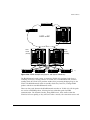
The switch supports up to the following number of concurrent user sessions:
• One console session
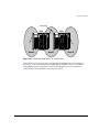
— Two console sessions are available on a BlackDiamond switch that has two
Management Switch Fabric Modules (MSMs) installed.
• Eight Telnet sessions
• Eight SSH2 sessions
• One Web session
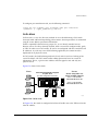
USING
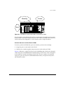
THE
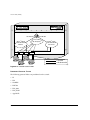
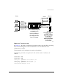
CONSOLE INTERFACE
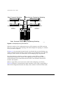
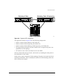
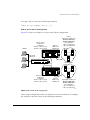
The CLI built into the switch is accessible by way of the 9-pin, RS-232 port labeled
console, located on the back of the Summit switch, or on the front of either of the
BlackDiamond switch MSMs.
For more information on the console port pinouts, refer to the BlackDiamond
Hardware Installation Guide or the Summit Hardware Installation Guide.
Once the connection is established, you will see the switch prompt and you may log in.
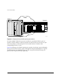
USING
THE
10/100 UTP MANAGEMENT PORT
Some Extreme switch models provide a dedicated 10/100 UTP management port. This
port provides dedicated remote access to the switch using TCP/IP. It supports the
following management methods:
• Telnet using the CLI interface
• ExtremeWare Vista Web access using a standard Web browser
• SNMP access using ExtremeWare Enterprise Manager or another SNMP manager
The management port is a DTE port, and is not capable of supporting switching or
routing functions. The TCP/IP configuration for the management port is done using the
same syntax as used for VLAN configuration. The VLAN mgmt comes preconfigured
with only the 10/100 UTP management port as a member.
3-2
EXTREMEWARE SOFTWARE USER GUIDE
USING TELNET
You can configure the IP address, subnet mask, and default router for the VLAN mgmt,
using the following commands:
config vlan mgmt ipaddress <ip_address>/<subnet_mask>
config iproute add default <gateway>
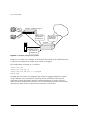
USING TELNET
Any workstation with a Telnet facility should be able to communicate with the switch
over a TCP/IP network.
Up to eight active Telnet sessions can access the switch concurrently. If idletimeouts
are enabled, the Telnet connection will time out after 20 minutes of inactivity. If a
connection to a Telnet session is lost inadvertently, the switch terminates the session
within two hours.
Before you can start a Telnet session, you must set up the IP parameters described in
the section “Configuring Switch IP Parameters,” later in this chapter. Telnet is enabled
by default.
To open the Telnet session, you must specify the IP address of the device that you want
to manage. Check the user manual supplied with the Telnet facility if you are unsure of
how to do this.
Once the connection is established, you will see the switch prompt and you may log in.
CONNECTING
TO
ANOTHER HOST USING TELNET
You can Telnet from the current CLI session to another host using the following
command:
telnet [<ipaddress> | <hostname>] {<port_number>}
If the TCP port number is not specified, the Telnet session defaults to port 23. Only
VT100 emulation is supported.
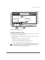
CONFIGURING SWITCH IP PARAMETERS
To manage the switch by way of a Telnet connection or by using an SNMP Network
Manager, you must first configure the switch IP parameters.
EXTREMEWARE SOFTWARE USER GUIDE
3-3
MANAGING
USING
THE
A
SWITCH
BOOTP SERVER
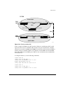
If you are using IP and you have a Bootstrap Protocol (BOOTP) server set up correctly
on your network, you must add the following information to the BOOTP server:
• Switch Media Access Control (MAC) address, found on the rear label of the switch
• IP address
• Subnet address mask (optional)
Once this is done, the IP address and subnet mask for the switch will be downloaded
automatically. You can then start managing the switch without further configuration.
You can enable BOOTP on a per-VLAN basis by using the following command:
enable bootp vlan [<name> | all]
By default, BOOTP is enabled on the default VLAN.
If you configure the switch to use BOOTP, the switch IP address is not retained through
a power cycle, even if the configuration has been saved. To retain the IP address
through a power cycle, you must configure the IP address of the VLAN using the
command-line interface, Telnet, or Web interface.
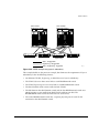
All VLANs within a switch that are configured to use BOOTP to get their IP address
use the same MAC address. Therefore, if you are using BOOTP relay through a router,
the BOOTP server must be capable of differentiating its relay based on the gateway
portion of the BOOTP packet.
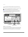
For more information on DHCP/BOOTP relay, refer to Chapter 11.
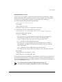
MANUALLY CONFIGURING
THE
IP SETTINGS
If you are using IP without a BOOTP server, you must enter the IP parameters for the
switch in order for the SNMP Network Manager, Telnet software, or Web interface to
communicate with the device. To assign IP parameters to the switch, you must do the
following:
• Log in to the switch with administrator privileges.
• Assign an IP address and subnet mask to a VLAN.
The switch comes configured with a default VLAN named default. To use Telnet or
an SNMP Network Manager, you must have at least one VLAN on the switch, and it
3-4
EXTREMEWARE SOFTWARE USER GUIDE
USING TELNET
must be assigned an IP address and subnet mask. IP addresses are always assigned
to a VLAN. The switch can be assigned multiple IP addresses.
For information on creating and configuring VLANs, refer to Chapter 6.
To manually configure the IP settings, perform the following steps:
1 Connect a terminal or workstation running terminal-emulation software to the
console port.
2 At your terminal, press [Return] one or more times until you see the login prompt.
3 At the login prompt, enter your user name and password. Note that they are both
case-sensitive. Ensure that you have entered a user name and password with
administrator privileges.
— If you are logging in for the first time, use the default user name admin to log in
with administrator privileges. For example:
login: admin
Administrator capabilities enable you to access all switch functions. The default
user names have no passwords assigned.
— If you have been assigned a user name and password with administrator
privileges, enter them at the login prompt.
4 At the password prompt, enter the password and press [Return].
When you have successfully logged in to the switch, the command-line prompt
displays the name of the switch in its prompt.
5 Assign an IP address and subnetwork mask for the default VLAN by using the
following command:
config vlan <name> ipaddress <ipaddress> {<subnet_mask>}
For example:
config vlan default ipaddress 123.45.67.8 255.255.255.0
Your changes take effect immediately.
As a general rule, when configuring any IP addresses for the switch, you can
express a subnet mask by using dotted decimal notation, or by using classless
inter-domain routing notation (CIDR). CIDR uses a forward slash plus the number
of bits in the subnet mask. Using CIDR notation, the command identical to the
one above would be:
config vlan default ipaddress 123.45.67.8 / 24
EXTREMEWARE SOFTWARE USER GUIDE
3-5
MANAGING
THE
SWITCH
6 Configure the default route for the switch using the following command:
config iproute add default <gateway> {<metric>}
For example:
config iproute add default 123.45.67.1
7 Save your configuration changes so that they will be in effect after the next switch
reboot, by typing
save
8 When you are finished using the facility, log out of the switch by typing
logout or quit
DISCONNECTING
A
TELNET SESSION
An administrator-level account can disconnect a Telnet management session. If this
happens, the user logged in by way of the Telnet connection is notified that the session
has been terminated.
To terminate a Telnet session, follow these steps:
1 Log in to the switch with administrator privileges.
2 Determine the session number of the session you want to terminate by using the
following command:
show session
3 Terminate the session by using the following command:
clear session <session_number>
CONTROLLING TELNET ACCESS
By default, Telnet services are enabled on the switch. Telnet access can be restricted by
the use of an access profile. An access profile permits or denies a named list of IP
addresses and subnet masks. To configure Telnet to use an access profile, use the
following command:
enable telnet {access-profile [<access_profile> | none]} {port
<tcp_port_number>}
Use the none option to remove a previously configured access profile.
3-6
EXTREMEWARE SOFTWARE USER GUIDE
USING SECURE SHELL 2 (SSH2)
To display the status of Telnet, use the following command:
show management
You can choose to disable Telnet by using the following command:
disable telnet
To re-enable Telnet on the switch, at the console port use the following command at the
console port:
enable telnet
You must be logged in as an administrator to enable or disable Telnet.
For more information on Access Profiles, see Chapter 16.
USING SECURE SHELL 2 (SSH2)
Secure Shell 2 (SSH2) is a feature of ExtremeWare that allows you to encrypt Telnet
session data between the switch and a network administrator using SSH2 client
software. The ExtremeWare SSH2 switch application is based on the Data Fellows™
SSH2 server implementation. It is highly recommended that you use the F-Secure SSH
client products from Data Fellows corporation. These applications are available for most
operating systems. For more information, refer to the Data Fellows website at:
http://www.datafellows.com.
SSH2 is compatible with the Data Fellows SSH2 client version 2.0.12 or above.
SSH2 is not compatible with SSH1.
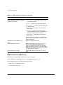
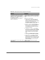
ENABLING SSH2
Because SSH2 is currently under U.S. export restrictions, before enabling SSH2, you
must first obtain a security license from Extreme Networks. The procedure for obtaining
a security license key is described in Chapter 1.
Once you have obtained the key, enable security licensing using the following
command:
enable license security <license key>
EXTREMEWARE SOFTWARE USER GUIDE
3-7
MANAGING
THE
SWITCH
To enable SSH2, use the following command:
enable ssh2 {access-profile [<access_profile> | none]} {port
<tcp_port_number>}
An authentication key must be generated for each SSH2 session. This can be done
automatically by the switch or by the client application. To have the key generated by
the switch, use the following command:
config ssh2 key {pregenerated}
If you do not select automatic key generation, you are prompted to enter the key when
you enable SSH2.
You can specify a list of pre-defined clients that are allowed SSH2 access to the switch.
To do this, you must create an access profile that contains a list of allowed IP addresses.
For more information on creating access profiles, refer to Chapter 16.
You can also specify a TCP port number to be used for SSH2 communication. By default
the TCP port number is 22.
The supported cipher is 3DES-CBC. The supported key exchange is DSA.
For additional information on the SSH protocol refer to [FIPS-186] Federal Information
Processing Standards Publication (FIPSPUB) 186, Digital Signature Standard, 18 May
1994. This can be download from: ftp://ftp.cs.hut.fi/pub/ssh. General technical
information is also available from http://www.ssh.fi.
After you obtain the SSH2 key value, copy the key to the SSH2 client application. Also,
ensure that the client is configured for any non-default access list or TCP port
information that you have configured on the switch. Once these tasks are accomplished,
you may form an SSH2-encrypted session with the switch.
USING EXTREMEWARE VISTA
ExtremeWare Vista is device-management software running in the switch that enables
you to access the switch over a TCP/IP network using a standard Web browser. Any
properly configured standard Web browser that supports frames (such as Netscape
Navigator 3.0 or above, or Microsoft Internet Explorer 3.0 or above) can manage the
switch over a TCP/IP network.
3-8
EXTREMEWARE SOFTWARE USER GUIDE
USING EXTREMEWARE VISTA
For more information on assigning an IP address, refer to the section,
“Configuring Switch IP Parameters,” on page 3-3.
The default home page of the switch can be accessed using the following command:
http://<ipaddress>
When you access the home page of the switch, you are presented with the Logon
screen.
For more information on using ExtremeWare Vista, refer to Chapter 19.
CONTROLLING WEB ACCESS
By default, Web access is enabled on the switch. Use of ExtremeWare Vista Web access
can be restricted through the use of an access profile. An access profile permits or
denies a named list of IP addresses and subnet masks. To configure Vista Web access to
use an access profile, use the following command:
enable web {access-profile <access-profile> | none} {port
<tcp_port_number>
Use the none option to remove a previously configured access profile.
To display the status of Web access, use the following command:
show management
To disable ExtremeWare Vista, use the following command:
disable web
To re-enable Web access, use the following command:
enable web {access-profile <access-profile> | none} {port
<tcp_port_number>
When you disable or enable ExtremeWare Vista, you must reboot the switch for the
changes to take effect. Apply an access profile only when ExtremeWare Vista is enabled.
EXTREMEWARE SOFTWARE USER GUIDE
3-9
MANAGING
THE
SWITCH
USING SNMP
Any Network Manager running the Simple Network Management Protocol (SNMP) can
manage the switch, provided the Management Information Base (MIB) is installed
correctly on the management station. Each Network Manager provides its own user
interface to the management facilities.
The following sections describe how to get started if you want to use an SNMP
manager. It assumes you are already familiar with SNMP management. If not, refer to
the following publication:
The Simple Book
by Marshall T. Rose
ISBN 0-13-8121611-9
Published by Prentice Hall
ACCESSING SWITCH AGENTS
To have access to the SNMP agent residing in the switch, at least one VLAN must have
an IP address assigned to it.
SUPPORTED MIBS
In addition to private MIBs, the switch supports the standard MIBs listed in
Appendix A.
CONFIGURING SNMP SETTINGS
The following SNMP parameters can be configured on the switch:
• Authorized trap receivers — An authorized trap receiver can be one or more
network management stations on your network. The switch sends SNMP traps to all
trap receivers. You can have a maximum of 16 trap receivers configured for each
switch. Entries in this list can also be created, modified, and deleted using the
RMON2 trapDestTable MIB variable, as described in RFC 2021.
• SNMP read access — The ability to read SNMP information can be restricted
through the use of an access profile. An access profile permits or denies a named list
of IP addresses and subnet masks.
3-10
EXTREMEWARE SOFTWARE USER GUIDE
USING SNMP
To configure SNMP read access to use an access profile, use the command:
config snmp access-profile readonly [<access_profile> | none]
Use the none option to remove a previously configured access profile.
• SNMP read/write access — The ability to read and write SNMP information can be
restricted through the use of an access profile. An access profile permits or denies a
named list of IP addresses and subnet masks.
To configure SNMP read/write access to use an access profile, use the command:
config snmp access-profile readwrite [<access_profile> | none]
Use the none option to remove a previously configured access-profile.
• Community strings — The community strings allow a simple method of
authentication between the switch and the remote Network Manager. There are two
types of community strings on the switch. Read community strings provide
read-only access to the switch. The default read-only community string is public.
Read-write community strings provide read and write access to the switch. The
default read-write community string is private. A total of eight community strings
can be configured on the switch. The community string for all authorized trap
receivers must be configured on the switch for the trap receiver to receive
switch-generated traps. SNMP community strings can contain up to 127 characters.
• System contact (optional) — The system contact is a text field that enables you to
enter the name of the person(s) responsible for managing the switch.
• System name — The system name is the name that you have assigned to this switch.
The default name is the model name of the switch (for example, Summit1 switch).
• System location (optional) — Using the system location field, you can enter an
optional location for this switch.
Table 3-1 describes SNMP configuration commands.
Table 3-1: SNMP Configuration Commands
Command
Description
config snmp access-profile readonly
[<access_profile> | none]
Assigns an access profile that limits which
stations have read-only access to the
switch.
config snmp access-profile readwrite
[<access_profile> | none]
Assigns an access profile that limits which
stations have read-write access to the
switch.
EXTREMEWARE SOFTWARE USER GUIDE
3-11
MANAGING
THE
SWITCH
Table 3-1: SNMP Configuration Commands (continued)
Command
Description
config snmp add trapreceiver <ipaddress>
community <string>
Adds the IP address of a specified trap
receiver. The IP address can be a unicast,
multicast, or broadcast address. A
maximum of 16 trap receivers is allowed.
config snmp community [read-only | read-write]
<string>
Adds an SNMP read or read/write
community string. The default read-only
community string is public. The default
read-write community string is
private. Each community string can
have a maximum of 127 characters, and
can be enclosed by double quotation
marks.
config snmp delete trapreceiver [<ip_address>
community <string> | all]
Deletes the IP address of a specified trap
receiver or all authorized trap receivers.
config snmp syscontact <string>
Configures the name of the system
contact. A maximum of 255 characters is
allowed.
config snmp syslocation <string>
Configures the location of the switch. A
maximum of 255 characters is allowed.
config snmp sysname <string>
Configures the name of the switch. A
maximum of 32 characters is allowed. The
default sysname is the model name of the
device (for example, Summit1). The
sysname appears in the switch prompt.
disable snmp access
Disables SNMP on the switch. Disabling
SNMP access does not affect the SNMP
configuration (for example, community
strings).
disable snmp traps
Prevents SNMP traps from being sent
from the switch. Does not clear the SNMP
trap receivers that have been configured.
enable snmp access
Turns on SNMP support for the switch.
enable snmp traps
Turns on SNMP trap support.
unconfig management
Restores default values to all
SNMP-related entries.
3-12
EXTREMEWARE SOFTWARE USER GUIDE
AUTHENTICATING USERS
DISPLAYING SNMP SETTINGS
To display the SNMP settings configured on the switch, use the following command:
show management
This command displays the following information:
• Enable/disable state for Telnet, SSH2, SNMP, and Web access, along with access
profile information
• SNMP community strings
• Authorized SNMP station list
• SNMP trap receiver list
• RMON polling configuration
• Login statistics
AUTHENTICATING USERS
ExtremeWare provides two methods to authenticate users who login to the switch:
• Radius client
• TACACS+
RADIUS CLIENT
Remote Authentication Dial In User Service (RADIUS, RFC 2138) is a mechanism for
authenticating and centrally administrating access to network nodes. The ExtremeWare
RADIUS client implementation allows authentication for Telnet, Vista, or console access
to the switch.
You cannot configure RADUIS and TACACS+ at the same time.
You can define a primary and secondary RADIUS server for the switch to contact.
When a user attempts to login using Telnet, http, or the console, the request is relayed
to the primary RADIUS server, and then to the secondary RADIUS server, if the
primary does not respond. If the RADIUS client is enabled, but access to the RADIUS
primary and secondary server fails, the switch uses its local database for authentication.
EXTREMEWARE SOFTWARE USER GUIDE
3-13
MANAGING
THE
SWITCH
The privileges assigned to the user (admin versus non-admin) at the RADIUS server
take precedence over the configuration in the local switch database.
PER-COMMAND AUTHENTICATION USING RADIUS
The RADIUS implementation can be used to perform per-command authentication.
Per-command authentication allows you to define several levels of user capabilities by
controlling the permitted command sets based on the RADIUS username and password.
You do not need to configure any additional switch parameters to take advantage of
this capability. The RADIUS server implementation automatically negotiates the
per-command authentication capability with the switch. For examples on per-command
RADIUS configurations, refer to the next section.
CONFIGURING RADIUS CLIENT
You can define primary and secondary server communication information, and for each
RADIUS server, the RADIUS port number to use when talking to the RADIUS server.
The default port value is 1645. The client IP address is the IP address used by the
RADIUS server for communicating back to the switch.
RADIUS commands are described in Table 3-2.
3-14
EXTREMEWARE SOFTWARE USER GUIDE
AUTHENTICATING USERS
Table 3-2: RADIUS Commands
Command
Description
config radius [primary | secondary] server
[<ipaddress> | <hostname>] {<udp_port>} client-ip
<ipaddress>
Configures the primary and secondary
RADIUS server. Specify the following:
■
[primary | secondary] —
Configure either the primary or
secondary RADIUS server.
■
[<ipaddress> | <hostname>] —
The IP address or hostname of the
server being configured.
■
<udp_port> — The UDP port to use
to contact the RADUIS server. The
default UDP port setting is 1645.
■
client-ip <ipaddress> — The IP
address used by the switch to identify
itself when communicating with the
RADIUS server.
The RADIUS server defined by this
command is used for user name
authentication and CLI command
authentication.
config radius [primary | secondary] shared-secret
<string>
Configures the authentication string used
to communicate with the RADIUS server.
config radius-accounting [primary | secondary]
server [<ipaddress> | <hostname>] {<udp_port>}
client-ip <ipaddress>
Configures the RADIUS accounting server.
Specify the following:
■
[primary | secondary] —
Configure either the primary or
secondary RADIUS server.
■
[<ipadress> | <hostname>] —
The IP address or hostname of the
server being configured.
■
<udp_port> — The UDP port to use
to contact the RADUIS server. The
default UDP port setting is 1646.
■
client-ip <ipaddress> — The IP
address used by the switch to identify
itself when communicating with the
RADIUS server.
The accounting server and the RADIUS
authentication server can be the same.
EXTREMEWARE SOFTWARE USER GUIDE
3-15
MANAGING
THE
SWITCH
Table 3-2: RADIUS Commands (continued)
Command
Description
config radius-accounting [primary | secondary]
shared-secret <string>
Configures the authentication string used
to communicate with the RADIUS
accounting server.
disable radius
Disables the RADIUS client.
disable radius-accounting
Disables RADIUS accounting.
enable radius
Enables the RADIUS client. When
enabled, all Web and CLI logins are sent
to the RADIUS servers for authentication.
When used with a RADIUS server that
supports ExtremeWare CLI authorization,
each CLI command is sent to the RADIUS
server for authentication before it is
executed.
enable radius-accounting
Enables RADIUS accounting. The RADIUS
client must also be enabled.
show radius
Displays the current RADIUS and RADIUS
accounting client configuration and
statistics.
RADIUS RFC 2138 ATTRIBUTES
The RADIUS RFC 2138 optional attributes supported are as follows:
• User-Name
• User-Password
• Service-Type
• Login-IP-Host
RADIUS SERVER CONFIGURATION EXAMPLE (MERIT)
Many implementations of RADIUS server use the publicly available “Merit© AAA”
server application, available on the World Wide Web at:
http://www.merit.edu/aaa
Included below are excerpts from relevant portions of a sample Merit RADIUS server
implementation. The example shows excerpts from the client and user configuration
3-16
EXTREMEWARE SOFTWARE USER GUIDE
AUTHENTICATING USERS
files. The client configuration file (ClientCfg.txt) defines the authorized source
machine, source name, and access level. The user configuration file (users) defines
username, password, and service type information.
ClientCfg.txt
#Client Name
#---------------#10.1.2.3:256
#pm1
#pm2
#merit.edu/homeless
#homeless
#xyz.merit.edu
#anyoldthing:1234
10.202.1.3
10.203.1.41
10.203.1.42
10.0.52.14
Key
[type]
[version]
--------------- -------------- --------test
type = nas
v2
%^$%#*(&!(*&)+
type=nas
:-):-(;^):-}!
type nas
hmoemreilte.ses
testing
type proxy
v1
moretesting
type=Ascend:NAS v1
whoknows?
type=NAS+RAD_RFC+ACCT_RFC
andrew-linux
type=nas
eric
type=nas
eric
type=nas
samf
type=nas
[prefix]
-------pfx
pm1.
pm2.
users
user
Password
Filter-Id =
admin
Password
Filter-Id =
eric
= ""
"unlim"
= "", Service-Type = Administrative
"unlim"
Password = "", Service-Type = Administrative
Filter-Id = "unlim"
albert
Password = "password", Service-Type = Administrative
Filter-Id = "unlim"
samuel
Password = "password", Service-Type = Administrative
Filter-Id = "unlim"
RADIUS PER-COMMAND CONFIGURATION EXAMPLE
Building on the example configuration above, you can use RADIUS to perform
per-command authentication to differentiate user capabilities. To do so, use the
Extreme-modified RADIUS Merit software that is available from the Extreme Networks
web server at http://www.extremenetworks.com/extreme/support/otherapps.htm or
by contacting Extreme Networks technical support. The software is available in
EXTREMEWARE SOFTWARE USER GUIDE
3-17
MANAGING
THE
SWITCH
compiled format for Solaris™ or Linux™ operating systems, as well as in source code
format. For all clients that use RADIUS per-command authentication, you must add the
following type to the client file:
type:extreme:nas + RAD_RFC + ACCT_RFC
Within the users configuration file, additional keywords are available for
Profile-Name and Extreme-CLI-Authorization. To use per-command authentication,
enable the CLI authorization function and indicate a profile name for that user. If
authorization is enabled without specifying a valid profile, the user is unable to perform
any commands.
Next, define the desired profiles in an ASCII configuration file called profiles. This file
contains named profiles of exact or partial strings of CLI commands. A named profile is
linked with a user through the users file. A profile with the permit on keywords
allows use of only the listed commands. A profile with the deny keyword allows use of
all commands except the listed commands.
CLI commands may be defined easily in a hierarchal manner by using an asterisk (*) to
indicate any possible subsequent entry. The parser performs exact string matches on
other text to validate commands. Commands are separated by a comma (,) or newline.
Looking at the following example content in profiles for the profile named PROFILE1,
which uses the deny keyword, the following attributes are associated with the user of
this profile:
• Cannot use any command starting with enable.
• Cannot issue the disable ipforwarding command.
• Cannot issue a show switch command.
• Can perform all other commands.
We know from the users file that this applies to the users albert and lulu. We also
know that eric is able to log in, but is unable to perform any commands, because he
has no valid profile assigned.
In PROFILE2, a user associated with this profile can use any enable command, the
clear counter command and the show management command, but can perform no
other functions on the switch. We also know from the users file that gerald has these
capabilities.
The following lists the contents of the file users with support for per-command
authentication:
3-18
EXTREMEWARE SOFTWARE USER GUIDE
AUTHENTICATING USERS
user
Password = ""
Filter-Id = "unlim"
admin
Password = "", Service-Type = Administrative
Filter-Id = "unlim"
eric
Password = "", Service-Type = Administrative, Profile-Name = ""
Filter-Id = "unlim"
Extreme:Extreme-CLI-Authorization = Enabled
albert Password = "", Service-Type = Administrative, Profile-Name =
"Profile1"
Filter-Id = "unlim"
Extreme:Extreme-CLI-Authorization = Enabled
lulu
Password = "", Service-Type = Administrative, Profile-Name =
"Profile1"
Filter-Id = "unlim"
Extreme:Extreme-CLI-Authorization = Enabled
gerald
Password = "", Service-Type = Administrative, Profile-Name
"Profile2"
Filter-Id = "unlim"
Extreme:Extreme-CLI-Authorization = Enabled
Contents of the file "profiles":
PROFILE1 deny
{
enable
*, disable ipforwarding
show switch
}
PROFILE2
{
enable *, clear counters
show
management
}
PROFILE3 deny
{
create vlan *, configure iproute *, disable *, show fdb
delete *, configure rip add
}
EXTREMEWARE SOFTWARE USER GUIDE
3-19
MANAGING
THE
SWITCH
CONFIGURING TACACS+
Terminal Access Controller Access Control System Plus (TACACS+) is a mechanism for
providing authentication, authorization, and accounting on a centralized server, similar
in function to the RADIUS client. The ExtremeWare version of TACACS+ is used to
authenticate prospective users who are attempting to administer the switch. TACACS+
is used to communicate between the switch and an authentication database.
You cannot use RADIUS and TACACS+ at the same time.
You can configure two TACACS+ servers, specifying the primary server address,
secondary server address, and UDP port number to be used for TACACS+ sessions.
Table 3-3 describes the commands that are used to configure TACACS+.
Table 3-3: TACACS+ Commands
Command
Description
config tacacs [primary | secondary] server
[<ipaddress> | <hostname>] {<udp_port>} client-ip
<ipaddress>
Configure the server information for a
TACACS+ server. Specify the following:
■
primary | secondary — Specifies
primary or secondary server
configuration. To remove a server, use
the address 0.0.0.0.
■
<ipaddress> | <hostname> —
Specifies the TACACS+ server.
■
<udp_port> — Optionally specifies
the UDP port to be used.
■
client-ip — Specifies the IP
address used by the switch to identify
itself when communicating with the
TACACS+ server.
config tacacs [primary | secondary] shared-secret
{encrypted} <string>
Configures the shared secret string used
to communicate with the TACACS+ server.
config tacacs-accounting [primary | secondary]
server [<ipaddress> | <hostname>] {<udp_port>}
client-ip <ipaddress>
Configures the TACACS+ accounting
server. You can use the same server for
accounting and authentication.
config tacacs-accounting [primary | secondary]
shared-secret {encrypted} <string>
Configures the shared secret string used
to communicate with the TACACS+
accounting server.
disable tacacs
Disables TACACS+.
3-20
EXTREMEWARE SOFTWARE USER GUIDE
USING
THE
SIMPLE NETWORK TIME PROTOCOL
Table 3-3: TACACS+ Commands (continued)
Command
Description
disable tacacs-accounting
Disables TACACS+ accounting.
disable tacacs-authorization
Disables CLI command authorization.
enable tacacs
Enables TACACS+. Once enabled, all
WEB and CLI logins are sent to one of the
two TACACS+ server for login name
authentication and accounting.
enable tacacs-accounting
Enables TACACS+ accounting. If
accounting is use, the TACACS+ client
must also be enabled.
enable tacacs-authorization
Enables CLI command authorization.
When enabled, each command is
transmitted to the remote TACACS+
server for authorization before the
command is executed.
show tacacs
Displays the current TACACS+
configuration and statistics.
show tacacs-accounting
Displays the current TACACS+ accounting
client configuration and statistics.
unconfig tacacs {server [primary | secondary]}
Unconfigures the TACACS+ client
configuration.
unconfig tacacs-accounting {server [primary |
secondary]}
Unconfigures the TACACS+ accounting
client configuration.
USING
THE
SIMPLE NETWORK TIME PROTOCOL
ExtremeWare supports the client portion of the Simple Network Time Protocol (SNTP)
Version 3 based on RFC1769. SNTP can be used by the switch to update and
synchronize its internal clock from a Network Time Protocol (NTP) server. When
enabled, the switch sends out a periodic query to the indicated NTP server, or the
switch listens to broadcast NTP updates. In addition, the switch supports the
configured setting for Greenwich Mean time (GMT) offset and the use of Daylight
Savings Time. These features have been tested for year 2000 compliance.
EXTREMEWARE SOFTWARE USER GUIDE
3-21
MANAGING
THE
SWITCH
CONFIGURING
AND
USING SNTP
To use SNTP, follow these steps:
1 Identify the host(s) that are configured as NTP server(s). Additionally, identify the
preferred method for obtaining NTP updates. The options are for the NTP server to
send out broadcasts, or for switches using NTP to query the NTP server(s) directly.
A combination of both methods is possible. You must identify the method that
should be used for the switch being configured.
2 Configure the Greenwich Mean Time (GMT) offset and Daylight Savings Time
preference. The command syntax to configure GMT offset and usage of Daylight
Savings is as follows:
config timezone <GMT_offset> {autodst | noautodst}
The GMT_OFFSET is in +/- minutes from the GMT time. Automatic Daylight
Savings Time (DST) changes can be enabled or disabled. The default setting is
enabled.
3 Enable the SNTP client using the following command:
enable sntp-client
Once enabled, the switch sends out a periodic query to the NTP servers defined later
(if configured) or listens to broadcast NTP updates from the network. The network
time information is automatically saved into the on-board real-time clock.
4 If you would like this switch to use a directed query to the NTP server, configure the
switch to use the NTP server(s). If the switch listens to NTP broadcasts, skip this
step. To configure the switch to use a directed query, use the following command:
config sntp-client [primary | secondary] server [<ip_address> |
<hostname>]
NTP queries are first sent to the primary server. If the primary server does not
respond within 1 second, or if it is not synchronized, the switch queries the
secondary server (if one is configured). If the switch cannot obtain the time, it
restarts the query process. Otherwise, the switch waits for the sntp-client update
interval before querying again.
5 Optionally, the interval for which the SNTP client updates the real-time clock of the
switch can be changed using the following command:
config sntp-client update-interval <seconds>
The default sntp-client update-interval value is 64 seconds.
6 You can verify the configuration using the following commands:
—
3-22
show sntp-client
EXTREMEWARE SOFTWARE USER GUIDE
USING
THE
SIMPLE NETWORK TIME PROTOCOL
This command provides configuration and statistics associated with SNTP and its
connectivity to the NTP server.
—
show switch
This command indicates the GMT offset, Daylight Savings Time, and the current
local time.
NTP updates are distributed using GMT time. To properly display the local time in logs
and other timestamp information, the switch should be configured with the appropriate
offset to GMT based on geographical location. Table 3-4 describes GMT offsets.
Table 3-4: Greenwich Mean Time Offsets
GMT
Offset in
Hours
GMT Offset Common Time Zone
in Minutes References
+0:00
+0
GMT - Greenwich Mean
UT or UTC - Universal
(Coordinated)
Cities
London, England; Dublin, Ireland;
Edinburgh, Scotland; Lisbon,
Portugal; Reykjavik, Iceland;
Casablanca, Morocco
WET - Western European
-1:00
-60
WAT - West Africa
Azores, Cape Verde Islands
-2:00
-120
AT - Azores
-3:00
-180
-4:00
-240
AST - Atlantic Standard
Caracas; La Paz
-5:00
-300
EST - Eastern Standard
Bogota, Columbia; Lima, Peru;
New York, NY, Trevor City, MI
USA
-6:00
-360
CST - Central Standard
Mexico City, Mexico
-7:00
-420
MST - Mountain Standard
Saskatchewan, Canada
-8:00
-480
PST - Pacific Standard
Los Angeles, CA, Cupertino, CA,
Seattle, WA USA
-9:00
-540
YST - Yukon Standard
-10:00
-600
AHST - Alaska-Hawaii Standard
Brasilia, Brazil; Buenos Aires,
Argentina; Georgetown, Guyana;
CAT - Central Alaska
HST - Hawaii Standard
-11:00
-660
EXTREMEWARE SOFTWARE USER GUIDE
NT - Nome
3-23
MANAGING
THE
SWITCH
Table 3-4: Greenwich Mean Time Offsets (continued)
GMT
Offset in
Hours
GMT Offset Common Time Zone
in Minutes References
-12:00
-720
IDLW - International Date Line
West
+1:00
+60
CET - Central European
+2:00
+120
EET - Eastern European, Russia Athens, Greece; Helsinki, Finland;
Zone 1
Istanbul, Turkey; Jerusalem,
Israel; Harare, Zimbabwe
+3:00
+180
BT - Baghdad, Russia Zone 2
Kuwait; Nairobi, Kenya; Riyadh,
Saudi Arabia; Moscow, Russia;
Tehran, Iran
+4:00
+240
ZP4 - Russia Zone 3
Abu Dhabi, UAE; Muscat; Tblisi;
Volgograd; Kabul
+5:00
+300
ZP5 - Russia Zone 4
+5:30
+330
IST – India Standard Time
+6:00
+360
ZP6 - Russia Zone 5
+7:00
+420
WAST - West Australian
Standard
+8:00
+480
CCT - China Coast, Russia Zone
7
+9:00
+540
JST - Japan Standard, Russia
Zone 8
+10:00
+600
EAST - East Australian Standard
Cities
Paris, France; Berlin, Germany;
Amsterdam, The Netherlands;
FWT - French Winter
Brussels, Belgium; Vienna,
MET - Middle European
Austria; Madrid, Spain; Rome,
Italy; Bern, Switzerland;
MEWT - Middle European Winter
Stockholm, Sweden; Oslo,
SWT - Swedish Winter
Norway
New Delhi, Pune, Allahabad,
India
GST - Guam Standard
Russia Zone 9
+11:00
+660
+12:00
+720
IDLE - International Date Line
East
Wellington, New Zealand; Fiji,
Marshall Islands
NZST - New Zealand Standard
NZT - New Zealand
3-24
EXTREMEWARE SOFTWARE USER GUIDE
USING
THE
SIMPLE NETWORK TIME PROTOCOL
SNTP CONFIGURATION COMMANDS
Table 3-5 describes SNTP configuration commands.
Table 3-5: SNTP Configuration Commands
Command
Description
config sntp-client [primary | secondary] server
[<ipaddress> | <host_name>]
Configures an NTP server for the switch to
obtain time information. Queries are first
sent to the primary server. If the primary
server does not respond within 1 second,
or if it is not synchronized, the switch
queries the second server.
config sntp-client update-interval <seconds>
Configures the interval between polling for
time information from SNTP servers. The
default setting is 64 seconds.
disable sntp-client
Disables SNTP client functions.
enable sntp-client
Enables Simple Network Time Protocol
(SNTP) client functions.
show sntp-client
Displays configuration and statistics for the
SNTP client.
SNTP EXAMPLE
In this example, the switch queries a specific NTP server and a backup NTP server. The
switch is located in Cupertino, CA, and an update occurs every 20 minutes. The
commands to configure the switch are as follows:
config
config
enable
config
config
timezone -480 autodst
sntp-client update interval 1200
sntp-client
sntp-client primary server 10.0.1.1
sntp-client secondary server 10.0.1.2
EXTREMEWARE SOFTWARE USER GUIDE
3-25
MANAGING
3-26
THE
SWITCH
EXTREMEWARE SOFTWARE USER GUIDE
4
Configuring BlackDiamond and
Alpine Switch Slots and Ports
This chapter covers the following topics:
• Configuring a Slot on page 4-1
• BlackDiamond and Alpine Switch Port Configuration on page 4-2
• Jumbo Frames on page 4-7
• Load Sharing on the BlackDiamond and Alpine Switch on page 4-7
• BlackDiamond and Alpine Switch Port-Mirroring on page 4-11
For information on configuring ports on the Summit switch, refer to Chapter 5.
CONFIGURING
A
SLOT
If a slot has not been configured for a particular type of I/O module, then any type of
module is accepted in that slot, and a default port and VLAN configuration is
automatically generated.
Once any port on the module is configured (for example, a VLAN association, a VLAN
tag configuration, or port parameters), all the port information and the module type for
that slot must be saved to non-volatile storage. Otherwise, if the BlackDiamond or
Alpine switch is rebooted or the module is removed from the slot, the port, VLAN, and
module configuration information is not saved.
For information on saving the configuration, refer to Chapter 20.
EXTREMEWARE SOFTWARE USER GUIDE
4-1
CONFIGURING BLACKDIAMOND
AND
ALPINE SWITCH SLOTS
AND
PORTS
You can configure the BlackDiamond or Alpine switch with the type of I/O module that
is installed in each I/O slot. To do this, use the following command:
config slot <slot> module [f32t | f32f | f48t | g4x | g6x | g8x |
g12x]
You can also pre-configure the slot before inserting the module card. This allows you to
begin configuring the module and ports before installing the card in the chassis.
If a slot is configured for one type of module, and a different type of module is inserted,
the inserted module is put into a mismatch state, and is not brought online. To use the
new module type in a slot, the slot configuration must be cleared or configured for the
new module type. To clear the slot of a previously assigned I/O module type, use the
following command:
clear slot <slot>
All configuration information related to the slot and the ports on the module is erased.
If a module is present when you issue this command, the module is reset to default
settings.
To display information about a particular slot, use the following command:
show slot {<slot>}
Information displayed includes the following:
• Card type, serial number, part number
• Current state (power down, operational, diagnostic, mismatch)
• Port information
If no slot is specified, information for all slots is displayed.
BLACKDIAMOND AND ALPINE SWITCH PORT
CONFIGURATION
On the BlackDiamond or Alpine switch, the port number is a combination of the slot
number and the port number. The nomenclature for the port number is as follows:
slot:port
4-2
EXTREMEWARE SOFTWARE USER GUIDE
BLACKDIAMOND
AND
ALPINE SWITCH PORT CONFIGURATION
For example, if a G4X I/O module (having a total of four ports) is installed in slot 2 of
the BlackDiamond 6808 chassis, the following ports are valid:
• 2:1
• 2:2
• 2:3
• 2:4
You can also use wildcard combinations (*) to specify multiple BlackDiamond or Alpine
slot and port combinations. The following wildcard combinations are allowed:
• slot:* — Specifies all ports on a particular I/O module.
• slot:x-slot:y — Specifies a contiguous series of ports on a particular I/O
module.
• slota:x-slotb:y — Specifies a contiguous series of ports that begin on one I/O
module and end on another I/O module.
ENABLING
PORTS
AND
DISABLING BLACKDIAMOND
AND
ALPINE SWITCH
By default, all ports are enabled. To enable or disable one or more ports, use the
following command:
[enable | disable] ports <portlist>
For example, to disable slot 7, ports 3, 5, and 12 through 15 on the BlackDiamond
switch, enter the following:
disable port 7:3,7:5,7:12-7:15
Even though a port is disabled, the link remains enabled for diagnostic purposes.
CONFIGURING BLACKDIAMOND
DUPLEX SETTING
AND
ALPINE SWITCH PORT SPEED
AND
By default, the switch is configured to use autonegotiation to determine the port speed
and duplex setting for each port. You can select to manually configure the duplex
setting and the speed of 10/100 Mbps ports, and you can manually configure the
duplex setting on Gigabit Ethernet ports.
EXTREMEWARE SOFTWARE USER GUIDE
4-3
CONFIGURING BLACKDIAMOND
AND
ALPINE SWITCH SLOTS
AND
PORTS
10BASE-T and 100BASE-TX ports can connect to either 10BASE-T or 100BASE-T
networks. By default, the ports autonegotiate port speed. You can also configure each
port for a particular speed (either 10 Mbps or 100 Mbps).
Gigabit Ethernet ports are statically set to 1 Gbps, and their speed cannot be modified.
To configure port speed and duplex setting, use the following command:
config ports <portlist> auto off {speed [10 | 100 | 1000]} duplex [half
| full]
To configure the system to autonegotiate, use the following command:
config ports <portlist> auto on
Flow control is supported only on Gigabit Ethernet ports. It is enabled or disabled as
part of autonegotiation.
TURNING OFF AUTONEGOTIATION
FOR A
GIGABIT ETHERNET PORT
In certain interoperability situations, you may need to turn autonegotiation off on a
Gigabit Ethernet port. Even though a Gigabit Ethernet port runs only at full duplex, you
must specify the duplex setting.
The following example turns autonegotiation off for port 1 on a G4X or G6X module
located in slot 1:
config ports 1:1 auto off duplex full
BLACKDIAMOND
AND
ALPINE SWITCH PORT COMMANDS
Table 4-1 describes the BlackDiamond and Alpine switch port commands.
Table 4-1: BlackDiamond and Alpine Switch Port Commands
Command
Description
clear slot <slot>
Clears a slot of a previously assigned module
type.
config jumbo-frame size <jumbo_frame_mtu> Configures the jumbo frame size. The range is
between 1523 and 9216, including 4 bytes of
CRC. The default setting is 9216.
4-4
EXTREMEWARE SOFTWARE USER GUIDE
BLACKDIAMOND
AND
ALPINE SWITCH PORT CONFIGURATION
Table 4-1: BlackDiamond and Alpine Switch Port Commands (continued)
Command
Description
config ports <portlist> auto off {speed [10 |
100 | 1000]} duplex [half | full]
Changes the configuration of a group of ports.
Specify the following:
■
auto off — The port will not autonegotiate
the settings.
■
speed — The speed of the port (for 10/100
Mbps or 100/1000 Mbps ports only).
■
duplex — The duplex setting (half- or
full-duplex).
config ports <portlist> auto on
Enables autonegotiation for the particular port
type; 802.3u for 10/100 Mbps ports or 802.3z for
Gigabit Ethernet ports.
config ports <portlist> display-string <string>
Configures a user-defined string for a port. The
string is displayed in certain show commands (for
example, show port all info). The string
can be up to 16 characters.
config ports <portlist> qosprofile <qosname>
Configures one or more ports to use a particular
QoS profile.
config slot <slot> module [f32t | f32f | f48t |
g4x | g6x | g8x | g12x]
Configures a slot for a particular I/O module card.
disable jumbo-frame ports [<portlist> | all]
Disables jumbo frame support on a port.
disable learning ports <portlist>
Disables MAC address learning on one or more
ports for security purposes. If MAC address
learning is disabled, only broadcast traffic,
Extreme Discovery Protocol (EDP) traffic, and
packets destined to a permanent MAC address
matching that port number are forwarded to the
port. The default setting is enabled.
disable ports <portlist>
Disables a port. Even when disabled, the link is
available for diagnostic purposes.
disable sharing <port>
Disables a load-sharing group of ports.
enable jumbo-frame ports [<portlist> | all]
Enables reception and transmission of jumbo
frames. A jumbo frame is dropped if it is received
on a port with jumbo frames disabled, or if the
jumbo frame needs to be forwarded out of a port
that has jumbo frames disabled.
enable learning ports <portlist>
Enables MAC address learning on one or more
ports. The default setting is enabled.
enable ports <portlist>
Enables a port.
EXTREMEWARE SOFTWARE USER GUIDE
4-5
CONFIGURING BLACKDIAMOND
AND
ALPINE SWITCH SLOTS
AND
PORTS
Table 4-1: BlackDiamond and Alpine Switch Port Commands (continued)
Command
Description
enable sharing <port> grouping <portlist>
{port-based | address-based | round-robin}
Defines a load-sharing group of ports. The ports
specified in <portlist> are grouped to the
master port. Optional load-sharing algorithms
include:
■
port-based — Uses the ingress port as criteria
for egress port selection.
■
address-based — Uses addressing
information as criteria for egress port
selection.
■
round-robin — Forwards packets to all egress
ports in a round-robin fashion.
If not specified, port-based load-sharing is used.
restart ports <portlist>
Resets autonegotiation for one or more ports by
resetting the physical link.
show ports {<portlist>} collisions
Displays real-time collision statistics.
show ports {<portlist>} configuration
Displays the port configuration.
show ports {<portlist>} info {detail}
Displays detailed system-related information.
show ports {<portlist>} packet
Displays a histogram of packet statistics.
show ports {<portlist>} qosmonitor
Displays real-time QoS statistics.
show ports {<portlist>} rxerrors
Displays real-time receive error statistics.
show ports {<portlist>} stats
Displays real-time port statistics.
show ports {<portlist>} txerrors
Displays real-time transmit error statistics.
show ports {<portlist>} utilization
Displays real-time port utilization information. Use
the [Spacebar] to toggle between packet, byte,
and bandwidth utilization information.
show slot {<slot>}
Displays slot-specific information, including the
following:
■
Card type, serial number, part number
■
Current state
■
Port information
If not slot is specified, information for all slots is
displayed.
unconfig ports <portlist> display-string
<string>
Clears the user-defined display string from a port.
unconfig slot <slot>
Clears a slot of a previously assigned module
type.
4-6
EXTREMEWARE SOFTWARE USER GUIDE
JUMBO FRAMES
JUMBO FRAMES
Jumbo frames are Ethernet frames that are larger than 1523 bytes, including four bytes
used for the cyclic redundancy check (CRC). Extreme products that use the “i” chipset
support switching and routing of jumbo frames at wire-speed on all ports.
Jumbo frames are used between endstations that support larger frame sizes for more
efficient transfers of bulk data. Both endstations involved in the transfer must be
capable of supporting jumbo frames. The switch does not perform IP fragmentation, or
participate in MTU negotiation on behalf of devices that do not support jumbo frames.
ENABLING JUMBO FRAMES
To enable jumbo frame support, you must configure the maximum MTU size of a jumbo
frame that will be allowed by the switch. To set the maximum MTU size, use the
following command
config jumbo-frame size <jumbo_frame_mtu>
The jumbo_frame_mtu range is 1523 to 9216. The value describes the maximum size
“on the wire,” and includes 4 bytes of CRC plus another 4 bytes if 802.1Q tagging is
being used.
Next, enable support on the physical ports that will carry jumbo frames, using the
following command:
enable jumbo-frame ports [<portlist | all]
Some network interface cards (NICs) have a configured maximum MTU size that
does not include the additional 4 bytes of CRC. Ensure that the NIC maximum
MTU size is at or below the maximum MTU size configured on the switch.
Frames that are larger than the MTU size configured on the switch are dropped
at the ingress port.
LOAD SHARING
SWITCH
ON THE
BLACKDIAMOND
AND
ALPINE
Load sharing with BlackDiamond or Alpine switches allows you to increase bandwidth
and resiliency by using a group of ports to carry traffic in parallel between switches.
The sharing algorithm allows the switch to use multiple ports as a single logical port.
EXTREMEWARE SOFTWARE USER GUIDE
4-7
CONFIGURING BLACKDIAMOND
AND
ALPINE SWITCH SLOTS
AND
PORTS
For example, VLANs see the load-sharing group as a single logical port. Most
load-sharing algorithms guarantee packet sequencing between clients.
If a port in a load-sharing group fails, traffic is redistributed to the remaining ports in
the load-sharing group. If the failed port becomes active again, traffic is redistributed to
include that port.
Load sharing must be enabled on both ends of the link, or a network loop may
result. The load-sharing algorithms do not need to be the same on both ends.
This feature is supported between Extreme Networks switches only, but may be
compatible with third-party “trunking” or link-aggregation algorithms. Check with an
Extreme Networks technical representative for more information.
LOAD-SHARING ALGORITHMS
Load sharing algorithms allow you to select the distribution technique used by the
load-sharing group to determine the output port selection. Algorithm selection is not
intended for use in predictive traffic engineering. You can configure one of three
load-sharing algorithms on the switch, as follows:
• Port-based — Uses the ingress port to determine which physical port in the
load-sharing group is used to forward traffic out of the switch.
• Address-based — Uses addressing information to determine which physical port in
the load-sharing group to use for forwarding traffic out of the switch. Addressing
information is based on the packet protocol, as follows:
— IP packets — Uses the source and destination MAC and IP addresses, and the
TCP port number.
— IPX packets — Uses the source and destination MAC address, and IPX network
identifiers.
— All other packets — Uses the source and destination MAC address.
• Round-robin — When the switch receives a stream of packets, it forwards one packet
out of each physical port in the load-sharing group using a round-robin scheme.
Using the round-robin algorithm, packet sequencing between clients is not
guaranteed.
If you do not explicitly select an algorithm, the port-based scheme is used. However,
the address-based algorithm has a more even distribution and is the recommended
choice.
4-8
EXTREMEWARE SOFTWARE USER GUIDE
LOAD SHARING
ON THE
BLACKDIAMOND
AND
ALPINE SWITCH
The address-based and round-robin load-sharing algorithms are supported by
BlackDiamond switch modules that use the “i” chipset and all Alpine 3800 switch
modules. The modules end with an “i” in their model designation (for example,
G12SXi), and require the use of the MSM64i. For more information on “i” chipset
products, refer to Chapter 1.
CONFIGURING BLACKDIAMOND
AND
ALPINE SWITCH LOAD SHARING
To set up the BlackDiamond or Alpine switch to load share among ports, you must
create a load-sharing group of ports. Load-sharing groups are defined according to the
following rules:
• The first port in the load-sharing group is configured to be the “master” logical port.
This is the reference port used in configuration commands. It can be thought of as
the logical port representing the entire port group.
On I/O modules that do not have the “i” chipset, the following additional rules apply:
• Ports in a load-sharing group must be contiguous.
• Ports on the I/O module are divided into groups of two or four.
Follow the outlined boxes in Table 4-2, Table 4-3, and Table 4-4 to determine the valid
port combinations.
Table 4-2, Table 4-3, and Table 4-4 show the possible load-sharing port group
combinations for the G4X module, the G6X module, and the F32T and F32F modules,
respectively.
Table 4-2: Port Combinations for the G4X Module
Load-Sharing
Group
1
2
3
4
4-port groups
x
x
x
x
2-port groups
x
x
x
x
EXTREMEWARE SOFTWARE USER GUIDE
4-9
CONFIGURING BLACKDIAMOND
AND
ALPINE SWITCH SLOTS
AND
PORTS
Table 4-3: Port Combinations for the G6X Module
Load-Sharing
Group
1
2
4-port groups
2-port groups
x
x
3
4
5
6
x
x
x
x
x
x
x
x
Table 4-4: Port Combinations for the F32T and F32F Modules
Load-Sharing
Group
1 1 1 1 1 1 1
1 2 3 4 5 6 7 8 9 0 1 2 3 4 5 6
4-port groups
x x
x x
x x
x
x x
x x
x
x x
x x
2-port groups
x x
x x
x x
x
x x
x x
x
x x
x x
Load-Sharing
Group
1 1 1 2 2 2 2 2 2 2 2 2 2 3 3 3
7 8 9 0 1 2 3 4 5 6 7 8 9 0 1 2
4-port groups
x x
x x
x x
x
x x
x x
x
x x
x x
2-port groups
x x
x x
x x
x
x x
x x
x
x x
x x
BlackDiamond switch modules that use the “i” chipset do not require contiguous ports
in the load-sharing group. On “i” chipset BlackDiamond switch modules, the following
rules apply:
• One group can contain up to 8 ports.
• The ports in the group must be on the same I/O module.
• The ports in the group do not need to be contiguous.
To define a load-sharing group, you assign a group of ports to a single, logical port
number. To enable or disable a load-sharing group, use the following commands:
enable sharing <port> grouping <portlist> {port-based | address-based |
round-robin}
disable sharing <port>
4-10
EXTREMEWARE SOFTWARE USER GUIDE
BLACKDIAMOND
AND
ALPINE SWITCH PORT-MIRRORING
LOAD-SHARING EXAMPLE
The following example defines a load-sharing group on slot 3 that contains ports 9
through 12, and uses the first port in the group as the master logical port 9:
enable sharing 3:9 grouping 3:9-3:12
In this example, logical port 3:9 represents physical ports 3:9 through 3:12.
When using load sharing, you should always reference the master logical port of the
load-sharing group (port 3:9 in the previous example) when configuring or viewing
VLANs. VLANs configured to use other ports in the load-sharing group will have those
ports deleted from the VLAN when load sharing becomes enabled.
Do not disable a port that is part of a load-sharing group. Disabling the port
prevents it from forwarding traffic, but still allows the link to initialize. As a result,
a partner switch does not receive a valid indication that the port is not in a
forwarding state, and the partner switch will continue to forward packets.
VERIFYING
THE
LOAD-SHARING CONFIGURATION
The screen output resulting from the show ports configuration command lists the
ports that are involved in load sharing and the master logical port identity.
BLACKDIAMOND
AND
ALPINE SWITCH PORT-MIRRORING
Port-mirroring configures the BlackDiamond or Alpine switch to copy all traffic
associated with one or more ports. The monitor port can be connected to a network
analyzer or RMON probe for packet analysis. The system uses a traffic filter that copies
a group of traffic to the monitor port. The traffic filter can be defined based on one of
the following criteria:
• Physical port — All data that traverses the port, regardless of VLAN configuration,
is copied to the monitor port.
• VLAN — All data to and from a particular VLAN, regardless of the physical port
configuration, is copied to the monitor port.
• Virtual port — All data specific to a VLAN on a specific port is copied to the
monitor port.
EXTREMEWARE SOFTWARE USER GUIDE
4-11
CONFIGURING BLACKDIAMOND
AND
ALPINE SWITCH SLOTS
AND
PORTS
Up to eight mirroring filters and one monitor port can be configured. Once a port is
specified as a monitor port, it cannot be used for any other function.
Frames that contain errors are not mirrored.
On switches that do not support the “i” chipset, mirrored frames that are
transmitted from the switch do not contain 802.1Q VLAN tagging information.
PORT-MIRRORING COMMANDS
BlackDiamond and Alpine switch port-mirroring commands are described in Table 4-5.
Table 4-5: BlackDiamond and Alpine Switch Port-Mirroring Configuration Commands
Command
Description
config mirroring add [vlan <name> | port
<port> | vlan <name> port <portlist>]
Adds a single mirroring filter definition. Up to eight
mirroring definitions can be added. You can mirror
traffic from a VLAN, a physical port, or a specific
VLAN/port combination.
config mirroring delete [vlan <name> | port Deletes a particular mirroring filter definition, or all
<slot:port> | vlan <name> port <portlist> | mirroring filter definitions.
all}
disable mirroring
Disables port-mirroring.
enable mirroring to <port>
Dedicates a port to be the mirror output port.
show mirroring
Displays the port-mirroring configuration.
BLACKDIAMOND SWITCH PORT-MIRRORING EXAMPLE
The following example selects port 3 on slot 7 as the mirror port, and sends all traffic
coming into or out of the BlackDiamond switch on slot 7, port 1 to the mirror port:
enable mirroring port 7:3
config mirroring add port 7:1
The following example sends all traffic coming into or out of the system on slot 8, port 1
and the VLAN default to the mirror port:
enable mirroring port 8:4
config mirroring add port 8:1 vlan default
4-12
EXTREMEWARE SOFTWARE USER GUIDE
BLACKDIAMOND
AND
ALPINE SWITCH PORT-MIRRORING
EXTREME DISCOVERY PROTOCOL
The Extreme Discovery Protocol (EDP) is used to gather information about neighbor
Extreme Networks switches. EDP is used to by the switches to exchange topology
information. EDP is also used by the Extreme Standby Router Protocol (ESRP),
described in Chapter 10. Information communicated using EDP includes the following:
• Switch MAC address (switch ID)
• Switch software version information
• Switch IP address
• Switch VLAN-IP information
• Switch port number
EDP COMMANDS
Table 4-6 lists EDP commands.
Table 4-6: EDP Commands
Command
Description
disable edp ports <portlist>
Disables the EDP on one or more ports.
enable edp ports <portlist>
Enables the generation and processing of EDP
messages on one or more ports. The default setting
is enabled.
show edp
Displays EDP information.
EXTREMEWARE SOFTWARE USER GUIDE
4-13
CONFIGURING BLACKDIAMOND
4-14
AND
ALPINE SWITCH SLOTS
AND
PORTS
EXTREMEWARE SOFTWARE USER GUIDE
5
Configuring Summit Switch Ports
This chapter covers the following topics:
• Enabling and Disabling Summit Switch Ports on page 5-1
• Configuring Summit Switch Port Speed and Duplex Setting on page 5-2
• Summit Switch Port Commands on page 5-3
• Jumbo Frames on page 5-5
• Load Sharing on the Summit Switch on page 5-6
• Summit Switch Port-Mirroring on page 5-10
• Smart Redundancy on page 5-13
For information on how to configure ports on the BlackDiamond or Alpine switch, refer
to Chapter 4.
ENABLING
AND
DISABLING SUMMIT SWITCH PORTS
By default, all ports are enabled. To enable or disable one or more ports, use the
following command:
[enable | disable] ports <portlist>
EXTREMEWARE SOFTWARE USER GUIDE
5-1
CONFIGURING SUMMIT SWITCH PORTS
For example, to disable ports 3, 5, and 12 through 15 on the Summit switch, enter the
following:
disable port 3,5,12-15
Even though a port is disabled, the link remains enabled for diagnostic purposes.
CONFIGURING SUMMIT SWITCH PORT SPEED
SETTING
AND
DUPLEX
By default, the Summit switch is configured to use autonegotiation to determine the
port speed and duplex setting for each port. You can select to manually configure the
duplex setting and the speed of 10/100 Mbps ports, and you can manually configure
the duplex setting on Gigabit Ethernet ports.
Fast Ethernet ports can connect to either 10Base-T or 100Base-T networks. By default,
the ports autonegotiate port speed. You can also configure each port for a particular
speed (either 10 Mbps or 100 Mbps).
Gigabit Ethernet ports are statically set to 1 Gbps, and their speed cannot be modified.
All ports on the Summit switch can be configured for half-duplex or full-duplex
operation. By default, the ports autonegotiate the duplex setting.
To configure port speed and duplex setting, use the following command:
config ports <portlist> auto off {speed [10 | 100 | 1000]} duplex [half
| full]
To configure the switch to autonegotiate, use the following command:
config ports <portlist> auto on
Flow control is supported only on Gigabit Ethernet ports. It is enabled or disabled as
part of autonegotiation. If autonegotiation is set to off, flow control is disabled. When
autonegotiation is turned on, flow control is enabled.
5-2
EXTREMEWARE SOFTWARE USER GUIDE
SUMMIT SWITCH PORT COMMANDS
TURNING OFF AUTONEGOTIATION
FOR A
GIGABIT ETHERNET PORT
In certain interoperability situations, it is necessary to turn autonegotiation off on a
Gigabit Ethernet port. Even though a Gigabit Ethernet port runs only at full duplex and
gigabit speeds, the command that turns off autonegotiation must still include the
duplex setting.
The following example turns autonegotiation off for port 4 (a Gigabit Ethernet port):
config ports 4 auto off duplex full
SUMMIT SWITCH PORT COMMANDS
Table 5-1 describes the Summit switch port commands.
Table 5-1: Summit Switch Port Commands
Command
Description
config jumbo-frame size <jumbo_frame_mtu> Configures the jumbo frame size. The range is
between 1523 and 9216. The default setting is
9216.
config ports <portlist> auto off {speed [10 |
100 | 1000]} duplex [half | full]
Changes the configuration of a group of ports.
Specify the following:
■
auto off — The port will not autonegotiate
the settings.
■
speed — The speed of the port (for 10/100
Mbps or 100/1000 Mbps ports only).
■
duplex — The duplex setting (half- or
full-duplex).
config ports <portlist> auto on
Enables autonegotiation for the particular port
type; 802.3u for 10/100 Mbps ports or 802.3z for
Gigabit Ethernet ports.
config ports <portlist> display-string <string>
Configures a user-defined string for a port. The
string is displayed in certain show commands (for
example, show port all info). The string
can be up to 16 characters.
config ports <portlist> qosprofile <qosname>
Configures one or more ports to use a particular
QoS profile.
disable jumbo-frame ports [<portlist> | all]
Disables jumbo frame support on a port.
EXTREMEWARE SOFTWARE USER GUIDE
5-3
CONFIGURING SUMMIT SWITCH PORTS
Table 5-1: Summit Switch Port Commands (continued)
Command
Description
disable learning ports <portlist>
Disables MAC address learning on one or more
ports for security purposes. If MAC address
learning is disabled, only broadcast traffic, EDP
traffic, and packets destined to a permanent MAC
address matching that port number, are
forwarded to the port. The default setting is
enabled.
disable ports <portlist>
Disables a port. Even when disabled, the link is
available for diagnostic purposes.
disable sharing <port>
Disables a load-sharing group of ports.
disable smartredundancy <portlist>
Disables the smart redundancy feature. If the
feature is disabled, the switch changes to the
active link only when the current active link
becomes inoperable.
enable jumbo-frame ports [<portlist> | all]
Enables reception and transmission of jumbo
frames. A jumbo frame is dropped if it is received
on a port with jumbo frames disabled, or if the
jumbo frame needs to be forwarded out of a port
that has jumbo frames disabled.
enable learning ports <portlist>
Enables MAC address learning on one or more
ports. The default setting is enabled.
enable ports <portlist>
Enables a port.
enable sharing <port> grouping <portlist>
{port-based | address-based | round-robin}
Defines a load-sharing group of ports. The ports
specified in <portlist> are grouped to the
master port. Optional load-sharing algorithms
include:
■
port-based — Uses the ingress port as criteria
for egress port selection.
■
address-based — Uses addressing
information as criteria for egress port
selection.
■
round-robin — Forwards packets to all egress
ports in a round-robin fashion.
If not specified, port-based load-sharing is used.
enable smartredundancy <portlist>
5-4
Enables the smart redundancy feature on the
redundant Gigabit Ethernet port. When the Smart
Redundancy feature is enabled, the switch
always uses the primary link when the primary
link is available. The default setting is enabled.
EXTREMEWARE SOFTWARE USER GUIDE
JUMBO FRAMES
Table 5-1: Summit Switch Port Commands (continued)
Command
Description
restart ports <portlist>
Resets autonegotiation for one or more ports by
resetting the physical link.
show ports {<portlist>} collisions
Displays real-time collision statistics.
show ports {<portlist>} configuration
Displays the port configuration.
show ports {<portlist>} info {detail}
Displays detailed system-related information.
show ports {<portlist>} packet
Displays a histogram of packet statistics.
show ports {<portlist>} qosmonitor
Displays real-time QoS statistics.
show ports {<portlist>} rxerrors
Displays real-time receive error statistics.
show ports {<portlist>} stats
Displays real-time port statistics.
show ports {<portlist>} txerrors
Displays real-time transmit error statistics.
show ports {<portlist>} utilization
Displays real-time port utilization information. Use
the [Spacebar] to toggle between packet, byte,
and bandwidth utilization information.
unconfig ports <portlist> display-string
<string>
Clears the user-defined display string from a port.
JUMBO FRAMES
Jumbo frames are Ethernet frames that are larger than 1523 bytes, including four bytes
used for the cyclic redundancy check (CRC). Extreme products that use the “i” chipset
support switching and routing of jumbo frames at wire-speed on all ports.
Jumbo frames are used between endstations that support larger frame sizes for more
efficient transfers of bulk data. Both endstations involved in the transfer must be
capable of supporting jumbo frames. The switch does not perform IP fragmentation, or
participate in MTU negotiation on behalf of devices that do not support jumbo frames.
ENABLING JUMBO FRAMES
To enable jumbo frame support, you must configure the maximum MTU size of a jumbo
frame that will be allowed by the switch. To set the maximum MTU size, use the
following command
config jumbo-frame size <jumbo_frame_mtu>
EXTREMEWARE SOFTWARE USER GUIDE
5-5
CONFIGURING SUMMIT SWITCH PORTS
The jumbo_frame_mtu range is 1523 to 9216. The value describes the maximum size
“on the wire,” and includes 4 bytes of CRC plus another 4 bytes if 802.1Q tagging is
being used.
Next, enable support on the physical ports that will carry jumbo frames, using the
following command:
enable jumbo-frame ports [<portlist | all]
Some network interface cards (NICs) have a configured maximum MTU size that
does not include the additional 4 bytes of CRC. Ensure that the NIC maximum
MTU size is at or below the maximum MTU size configured on the switch.
Frames that are larger than the MTU size configured on the switch are dropped
at the ingress port.
LOAD SHARING
ON THE
SUMMIT SWITCH
Load sharing with Summit switches allows you to increase bandwidth and resilience
between switches by using a group of ports to carry traffic in parallel between switches.
The sharing algorithm allows the switch to use multiple ports as a single logical port.
For example, VLANs see the load-sharing group as a single logical port. Most
load-sharing algorithms also guarantee packet sequencing between clients.
If a port in a load-sharing group fails, traffic is redistributed to the remaining ports in
the load-sharing group. If the failed port becomes active again, traffic is redistributed to
include that port.
Load sharing must be enabled on both ends of the link, or a network loop will
result.
This feature is supported between Extreme Networks switches only, but may be
compatible with third-party “trunking” or sharing algorithms. Check with an Extreme
Networks technical representative for more information.
5-6
EXTREMEWARE SOFTWARE USER GUIDE
LOAD SHARING
ON THE
SUMMIT SWITCH
LOAD SHARING ALGORITHMS
Load sharing algorithms allow you to select the distribution technique used by the
load-sharing group to determine the output port selection. Algorithm selection is not
intended for use in predictive traffic engineering.
You can configure one of three load-sharing algorithms on the switch, as follows:
• Port-based — Uses the ingress port to determine which physical port in the
load-sharing group is used to forward traffic out of the switch.
• Address-based — Uses addressing information to determine which physical port in
the load-sharing group to use for forwarding traffic out of the switch. Addressing
information is based on the packet protocol, as follows:
— IP packets — Uses the source and destination MAC and IP addresses, and the
TCP port number.
— IPX packets — Uses the source and destination MAC address, and IPX network
identifiers.
— All other packets — Uses the source and destination MAC address.
• Round-robin — When the switch receives a stream of packets, it forwards one packet
out of each physical port in the load-sharing group using a round-robin scheme.
Using the round-robin algorithm, packet sequencing between clients is not
guaranteed.
If you do not explicitly select an algorithm, the port-based scheme is used. However,
the address-based algorithm has a more even distribution and is the recommended
choice.
The address-based and round-robin load sharing algorithms are supported by Summit
switch products that use the “i” chipset, such as the Summit7i switch. For more
information on the “i” chipset products, refer to Chapter 1.
CONFIGURING SUMMIT SWITCH LOAD SHARING
To set up the Summit switch to load share among ports, you must create a load-sharing
group of ports. The first port in the load-sharing group is configured to be the “master”
logical port. This is the reference port used in configuration commands. It can be
thought of as the logical port representing the entire port group.
EXTREMEWARE SOFTWARE USER GUIDE
5-7
CONFIGURING SUMMIT SWITCH PORTS
On switches that do not have the “i” chipset, the following additional rules apply:
• Ports in a load-sharing group must be contiguous.
• Ports on the switch are divided into groups of two or four.
• Address-based and round-robin load sharing algorithms do not apply.
Follow the outlined boxes in Table 5-2 through Table 5-7 to determine the valid port
combinations.
Table 5-2, Table 5-3, Table 5-4, Table 5-5, Table 5-6, and Table 5-7 show the possible
load-sharing port group combinations for the Summit1, Summit2, Summit3, Summit24,
Summit4 and Summit4/FX, and Summit48 switches, respectively.
Table 5-2: Port Combinations for the Summit1 Switch
Load-Sharing
Group
1
2
3
*
x
x
4-port groups
2-port groups
4
5
6
7
x
x
x
x
x
x
x
x
8
*
* In addition, ports 1 and 8 can be combined into a two-port load sharing group on the
Summit1.
Table 5-3: Port Combinations for the Summit2 Switch
Load-Sharing
Group
1
2
3
4
5
6
7
8
9
4-port groups
x
x
x
x
x
x
x
x
x
x
x
x
x
x
x
x
2-port groups
x
x
x
x
x
x
x
x
x
x
x
x
x
x
x
x
10 11 12 13 14 15 16 17 18
x
x
Table 5-4: Port Combinations for the Summit3 Switch
Load-Sharing
Group
1 1 1 1 1 1 1 1 1 1 2 2 2 2 2 2
1 2 3 4 5 6 7 8 9 0 1 2 3 4 5 6 7 8 9 0 1 2 3 4 5
4-port groups
x x x x x x x x x x x x x x x x x x x x x x x x
2-port groups
x x x x x x x x x x x x x x x x x x x x x x x x
5-8
EXTREMEWARE SOFTWARE USER GUIDE
LOAD SHARING
ON THE
SUMMIT SWITCH
Table 5-5: Port Combinations for the Summit4 Switch and Summit4/FX Switch
Load-Sharing
Group
1
2
3
4
5
6
7
8
9
1
0
1
1
1
2
1
3
1
4
1
5
1
6
4-port groups
x
x
x
x
x
x
x
x
x
x
x
x
x
x
x
x
2-port groups
x
x
x
x
x
x
x
x
x
x
x
x
x
x
x
x
1
7
x
1
8
x
1
9
2
0
2
1
2
2
x
x
x
x
x
x
x
x
Table 5-6: Port Combinations for the Summit24 Switch
Load-Sharing
Group
1 1 1 1 1 1 1 1 1 1 2 2 2 2 2 2
1 2 3 4 5 6 7 8 9 0 1 2 3 4 5 6 7 8 9 0 1 2 3 4 5
4-port groups
x x x x x x x x x x x x x x x x x x x x x x x x
2-port groups
x x x x x x x x x x x x x x x x x x x x x x x x
Table 5-7: Port Combinations for the Summit48 Switch
Load-Sharing
Group
1 1 1 1 1 1 1 1 1 1 2 2 2 2 2
1 2 3 4 5 6 7 8 9 0 1 2 3 4 5 6 7 8 9 0 1 2 3 4
4-port groups
x x
x x
x
x x
x x
x x
x
x x
x x
x
x x
x x
x
x x
2-port groups
x x
x x
x
x x
x x
x x
x
x x
x x
x
x x
x x
x
x x
Load-Sharing
Group
2 2 2 2 2 3 3 3 3 3 3 3 3 3 3 4 4 4 4 4 4 4 4 4
5 6 7 8 9 0 1 2 3 4 5 6 7 8 9 0 1 2 3 4 5 6 7 8
4-port groups
x x
x x
x
x x
x x
x x
x
x x
x x
x
x x
x x
x
x x
2-port groups
x x
x x
x
x x
x x
x x
x
x x
x x
x
x x
x x
x
x x
Load-Sharing
Group
4 5
9 0
4-port groups
2-port groups
x x
On all other Summit switch models, the following rules apply:
• A group can contain up to 8 ports.
• The ports in a group to not need to be contiguous.
EXTREMEWARE SOFTWARE USER GUIDE
5-9
CONFIGURING SUMMIT SWITCH PORTS
To define a load-sharing group, you assign a group of ports to a single, logical port
number. To enable or disable a load-sharing group, use the following commands:
enable sharing <port> grouping <portlist> {port-based | address-based |
round-robin}
disable sharing <port>
LOAD-SHARING EXAMPLE
The following example defines a load-sharing group that contains ports 9 through 12,
and uses the first port in the group as the master logical port 9:
enable sharing 9 grouping 9-12
In this example, logical port 9 represents physical ports 9 through 12.
When using load sharing, you should always reference the master logical port of the
load-sharing group (port 9 in the previous example) when configuring or viewing
VLANs. VLANs configured to use other ports in the load-sharing group will have those
ports deleted from the VLAN when load sharing becomes enabled.
Do not disable a port that is part of a load-sharing group. Disabling the port
prevents it from forwarding traffic, but still allows the link to initialize. As a result,
a partner switch does not receive a valid indication that the port is not in a
forwarding state, and the partner switch will continue to forward packets.
VERIFYING
THE
LOAD SHARING CONFIGURATION
The screen output resulting from the show ports configuration command indicates
the ports are involved in load sharing and the master logical port identity.
SUMMIT SWITCH PORT-MIRRORING
Port-mirroring configures the switch to copy all traffic associated with one or more
ports to a monitor port on the switch. The monitor port can be connected to a network
analyzer or RMON probe for packet analysis. The switch uses a traffic filter that copies
a group of traffic to the monitor port.
5-10
EXTREMEWARE SOFTWARE USER GUIDE
SUMMIT SWITCH PORT-MIRRORING
The traffic filter can be defined based on one of the following criteria:
• Physical port — All data that traverses the port, regardless of VLAN configuration,
is copied to the monitor port.
• VLAN — All data to and from a particular VLAN, regardless of the physical port
configuration, is copied to the monitor port.
• Virtual port — All data specific to a VLAN on a specific port is copied to the
monitor port.
Up to eight mirroring filters and one monitor port can be configured on the switch.
Once a port is specified as a monitor port, it cannot be used for any other function.
Frames that contain errors are not mirrored.
On switches that do not support the “i” chipset, mirrored frames that are
transmitted from the switch do not contain 802.1Q VLAN tagging information.
PORT-MIRRORING COMMANDS
Summit switch port-mirroring commands are described in Table 5-8.
Table 5-8: Summit Switch Port-Mirroring Configuration Commands
Command
Description
config mirroring add [vlan <name> | port
<port> | vlan <name> port <port>]
Adds a single mirroring filter definition. Up to eight
mirroring definitions can be added. You can mirror
traffic from a VLAN, a physical port, or a specific
VLAN/port combination.
config mirroring delete [vlan <name> | port Deletes a particular mirroring filter definition, or all
<port> | vlan <name> port <port> | all}
mirroring filter definitions.
disable mirroring
Disables port-mirroring.
enable mirroring to <port>
Dedicates a port to be the mirror output port.
show mirroring
Displays the port-mirroring configuration.
EXTREMEWARE SOFTWARE USER GUIDE
5-11
CONFIGURING SUMMIT SWITCH PORTS
SUMMIT SWITCH PORT-MIRRORING EXAMPLE
The following example selects port 3 as the mirror port, and sends all traffic coming
into or out of the switch on port 1 to the mirror port:
enable mirroring to port 3
config mirroring add port 1
The following example sends all traffic coming into or out of the switch on port 1 and
the VLAN default to the mirror port:
config mirroring add port 1 vlan default
EXTREME DISCOVERY PROTOCOL
The Extreme Discovery Protocol (EDP) is used to gather information about neighbor
Extreme Networks switches. EDP is used to by the switches to exchange topology
information. EDP is also used by the Extreme Standby Router Protocol (ESRP),
described in Chapter 10. Information communicated using EDP includes the following:
• Switch MAC address (switch ID)
• Switch software version information
• Switch IP address
• Switch VLAN-IP information
• Switch port number
EDP COMMANDS
Table 5-9 lists EDP commands.
Table 5-9: EDP Commands
Command
Description
disable edp ports <portlist>
Disables the EDP on one or more ports.
enable edp ports <portlist>
Enables the generation and processing of EDP
messages on one or more ports. The default setting
is enabled.
show edp
Displays EDP information.
5-12
EXTREMEWARE SOFTWARE USER GUIDE
SMART REDUNDANCY
SMART REDUNDANCY
Smart redundancy defines the behavior of switches equipped with redundancy Gigabit
Ethernet ports (for example, the Summit 24 and Summit48). When the switch becomes
operational, it attempts to establish connectivity on the primary link. If this fails, the
redundancy port is attempted. When connectivity is established (or re-established) on
the primary link, the primary link is used.
On the Summit48, which has two redundant Gigabit Ethernet ports, an additional
capability is provided when both ports are configured for load-sharing. Using this
configuration, the same failover actions apply simultaneously to both failover ports. For
example, if the primary connection on port 49 fails, the redundant port on both port 49
and 50 are activated simultaneously. When connectivity is re-established on the primary
links of both ports 49 and 50, the primary links are used.
Figure 5-1 shows a load-shared link with smart redundancy failover.
Primary links
Failover links
49
49R
50
50R
EW_047
Figure 5-1: Load-shared link with smart redundancy failover
EXTREMEWARE SOFTWARE USER GUIDE
5-13
CONFIGURING SUMMIT SWITCH PORTS
If smart redundancy is disabled, both the primary and redundant ports are dual-homed
to active Gigabit Ethernet ports. It is not possible to predict which port will become
active, and the first port to initialize becomes the primary. Enabling smart redundancy
allows you to predict port failover and fail-back behavior.
5-14
EXTREMEWARE SOFTWARE USER GUIDE
6
Virtual LANs (VLANs)
This chapter covers the following topics:
• Overview of Virtual LANs on page 6-1
• Types of VLANs on page 6-2
• VLAN Names on page 6-12
• Configuring VLANs on the Switch on page 6-13
• Displaying VLAN Settings on page 6-16
• Generic VLAN Registration Protocol on page 6-17
• MAC-Based VLANs on page 6-20
Setting up Virtual Local Area Networks (VLANs) on the switch eases many
time-consuming tasks of network administration while increasing efficiency in network
operations.
OVERVIEW
OF
VIRTUAL LANS
The term “VLAN” is used to refer to a collection of devices that communicate as if they
were on the same physical LAN. Any set of ports (including all ports on the switch) is
considered a VLAN. LAN segments are not restricted by the hardware that physically
connects them. The segments are defined by flexible user groups you create with the
command-line interface.
EXTREMEWARE SOFTWARE USER GUIDE
6-1
VIRTUAL LANS (VLANS)
BENEFITS
Implementing VLANs on your networks has the following advantages:
• VLANs help to control traffic.
With traditional networks, congestion can be caused by broadcast traffic that is
directed to all network devices, regardless of whether they require it. VLANs
increase the efficiency of your network because each VLAN can be set up to contain
only those devices that must communicate with each other.
• VLANs provide extra security.
Devices within each VLAN can only communicate with member devices in the same
VLAN. If a device in VLAN Marketing must communicate with devices in VLAN
Sales, the traffic must cross a routing device.
• VLANs ease the change and movement of devices.
With traditional networks, network administrators spend much of their time dealing
with moves and changes. If users move to a different subnetwork, the addresses of
each endstation must be updated manually.
TYPES
OF
VLANS
VLANs can be created according to the following criteria:
• Physical port
• 802.1Q tag
• Ethernet, LLC SAP, or LLC/SNAP Ethernet protocol type
• MAC address
• A combination of these criteria
PORT-BASED VLANS
In a port-based VLAN, a VLAN name is given to a group of one or more ports on the
switch. A port can be a member of only one port-based VLAN.
For example, on the Summit7i switch in Figure 6-1, ports 9 through 14 are part of
VLAN Marketing; ports 25 through 29 are part of VLAN Sales; and ports 21 through 24
and 30 through 32 are in VLAN Finance.
6-2
EXTREMEWARE SOFTWARE USER GUIDE
TYPES
VLANS
Finance
Marketing
Sales
OF
1
2
3
4
5
6
7
8
9
10
11
12
13
14
15
16
17
18
19
20
22
23
25
26
27
28
21
29
30
24
31
32
EW_027
Figure 6-1: Example of a port-based VLAN on the Summit7i switch
For the members of the different IP VLANs to communicate, the traffic must be routed
by the switch, even if they are physically part of the same I/O module. This means that
each VLAN must be configured as a router interface with a unique IP address.
SPANNING SWITCHES
WITH
PORT-BASED VLANS
To create a port-based VLAN that spans two switches, you must do two things:
1 Assign the port on each switch to the VLAN.
2 Cable the two switches together using one port on each switch per VLAN.
Figure 6-2 illustrates a single VLAN that spans a BlackDiamond switch and a Summit7i
switch. All ports on the BlackDiamond switch belong to VLAN Sales. Ports 1 through 29
on the Summit 7i switch also belong to VLAN Sales. The two switches are connected
using slot 8, port 4 on System 1 (the BlackDiamond switch), and port 29 on System 2
(the Summit7i switch).
EXTREMEWARE SOFTWARE USER GUIDE
6-3
VIRTUAL LANS (VLANS)
Sales
System 1
1
2
3
4
A
B
5
6
7
System 2
8
1
2
3
4
5
6
7
8
9
10
11
12
13
14
15
16
17
18
19
20
22
23
25
26
27
28
21
24
1
29
30
31
32
2
3
4
EW_028
Figure 6-2: Single port-based VLAN spanning two switches
To create multiple VLANs that span two switches in a port-based VLAN, a port on
System 1 must be cabled to a port on System 2 for each VLAN you want to have span
across the switches. At least one port on each switch must be a member of the
corresponding VLANs, as well.
Figure 6-3 illustrates two VLANs spanning two switches. On System 1, ports 25 through
29 are part of VLAN Accounting; ports 21 through 24 and ports 30 through 32 are part of
VLAN Engineering. On System 2, all port on slot 3 are part of VLAN Accounting; all
ports on slot 7 are part of VLAN Engineering.
6-4
EXTREMEWARE SOFTWARE USER GUIDE
TYPES
OF
VLANS
System 1
1
2
3
4
A
B
5
6
7
8
50015
1
1
2
2
3
3
4
4
5
5
6
6
Engineering
Accounting
System 2
1
2
3
4
5
6
7
8
9
10
11
12
13
14
15
16
17
18
19
20
22
23
25
26
27
28
21
29
30
24
31
32
EW_030
Figure 6-3: Two port-based VLANs spanning two BlackDiamond switches
VLAN Accounting spans System 1 and System 2 by way of a connection between
System 1, 29 and System 2, slot 3, port 1. VLAN Engineering spans System 1 and System
2 by way of a connection between System 1, port 32, and System 2, slot 7, port 1.
Using this configuration, you can create multiple VLANs that span multiple switches, in
a daisy-chained fashion. Each switch must have a dedicated port for each VLAN. Each
dedicated port must be connected to a port that is a member of its VLAN on the next
switch.
EXTREMEWARE SOFTWARE USER GUIDE
6-5
VIRTUAL LANS (VLANS)
TAGGED VLANS
Tagging is a process that inserts a marker (called a tag) into the Ethernet frame. The tag
contains the identification number of a specific VLAN, called the VLANid.
The use of 802.1Q tagged packets may lead to the appearance of packets
slightly bigger than the current IEEE 802.3/Ethernet maximum of 1,518 bytes.
This may affect packet error counters in other devices, and may also lead to
connectivity problems if non-802.1Q bridges or routers are placed in the path.
USES
OF
TAGGED VLANS
Tagging is most commonly used to create VLANs that span switches. The
switch-to-switch connections are typically called trunks. Using tags, multiple VLANs
can span multiple switches using one or more trunks. In a port-based VLAN, each
VLAN requires its own pair of trunk ports, as shown in Figure 6-3. Using tags, multiple
VLANs can span two switches with a single trunk.
Another benefit of tagged VLANs is the ability to have a port be a member of multiple
VLANs. This is particularly useful if you have a device (such as a server) that must
belong to multiple VLANs. The device must have a NIC that supports 802.1Q tagging.
A single port can be a member of only one port-based VLAN. All additional VLAN
membership for the port must be accompanied by tags. In addition to configuring the
VLAN tag for the port, the server must have a Network Interface Card (NIC) that
supports 802.1Q tagging.
ASSIGNING
A
VLAN TAG
Each VLAN may be assigned an 802.1Q VLAN tag. As ports are added to a VLAN with
an 802.1Q tag defined, you decide whether each port will use tagging for that VLAN.
The default mode of the switch is to have all ports assigned to the VLAN named default
with an 802.1Q VLAN tag (VLANid) of 1 assigned.
Not all ports in the VLAN must be tagged. As traffic from a port is forwarded out of
the switch, the switch determines (in real time) if each destination port should use
tagged or untagged packet formats for that VLAN. The switch adds and strips tags, as
required, by the port configuration for that VLAN.
Packets arriving tagged with a VLANid that is not configured on a port will be
discarded.
6-6
EXTREMEWARE SOFTWARE USER GUIDE
TYPES
OF
VLANS
Figure 6-4 illustrates the physical view of a network that uses tagged and untagged
traffic.
System 1
M = Marketing
S = Sales
= Tagged port
Marketing & Sales
M
S
S
802.1Q
Tagged server
1
2
3
4
A
B
5
6
7
8
50015
M
M
1
M
S
2
S
3
S
S
4
System 2
EW_029
Figure 6-4: Physical diagram of tagged and untagged traffic
EXTREMEWARE SOFTWARE USER GUIDE
6-7
VIRTUAL LANS (VLANS)
Figure 6-5 shows a logical diagram of the same network.
Marketing
Sales
System 1
Ports 1-4 & 9-12
System 1
Port 25 *
Port 29 *
System 1
Ports 5-8, 13-16 & 32
System 2
Slot 1, Port 2
Slot 2, Ports 1-8 & 17-24
System 2
Slot 1, Port 1 *
System 2
Slot 1, Port 3
Slot 1, Port 4
Slot 2, Ports 9-16 & 25-32
*Tagged Ports
EW_025
Figure 6-5: Logical diagram of tagged and untagged traffic
In Figure 6-4 and Figure 6-5:
• The trunk port on each switch carries traffic for both VLAN Marketing and VLAN
Sales.
• The trunk port on each switch is tagged.
• The server connected to port 25 on System 1 has a NIC that supports 802.1Q tagging.
• The server connected to port 25 on System 1 is a member of both VLAN Marketing
and VLAN Sales.
• All other stations use untagged traffic.
As data passes out of the switch, the switch determines if the destination port requires
the frames to be tagged or untagged. All traffic coming from and going to the server is
tagged. Traffic coming from and going to the trunk ports is tagged. The traffic that
comes from and goes to the other stations on this network is not tagged.
6-8
EXTREMEWARE SOFTWARE USER GUIDE
TYPES
MIXING PORT-BASED
AND
OF
VLANS
TAGGED VLANS
You can configure the switch using a combination of port-based and tagged VLANs. A
given port can be a member of multiple VLANs, with the stipulation that only one of its
VLANs uses untagged traffic. In other words, a port can simultaneously be a member of
one port-based VLAN and multiple tag-based VLANs.
For the purposes of VLAN classification, packets arriving on a port with an
802.1Q tag containing a VLANid of zero are treated as untagged.
PROTOCOL-BASED VLANS
Protocol-based VLANs enable you to define a packet filter that the switch uses as the
matching criteria to determine if a particular packet belongs to a particular VLAN.
Protocol-based VLANs are most often used in situations where network segments
contain hosts running multiple protocols. For example, in Figure 6-6, the hosts are
running both the IP and NetBIOS protocols.
The IP traffic has been divided into two IP subnets, 192.207.35.0 and 192.207.36.0. The
subnets are internally routed by the switch. The subnets are assigned different VLAN
names, Finance and Personnel, respectively. The remainder of the traffic belongs to the
VLAN named MyCompany. All ports are members of the VLAN MyCompany.
EXTREMEWARE SOFTWARE USER GUIDE
6-9
VIRTUAL LANS (VLANS)
1
2
3
4
A
192.207.35.1
B
5
6
7
8
192.207.36.1
My Company
192.207.35.0
Finance
1
2
192.207.36.0
Personnel
3
4
= IP traffic
= All other traffic
BD_007
Figure 6-6: Protocol-based VLANs
PREDEFINED PROTOCOL FILTERS
The following protocol filters are predefined on the switch:
• IP
• IPX
• NetBIOS
• DECNet
• IPX_8022
• IPX_SNAP
• AppleTalk
6-10
EXTREMEWARE SOFTWARE USER GUIDE
TYPES
OF
VLANS
DEFINING PROTOCOL FILTERS
If necessary, you can define a customized protocol filter based on EtherType, Logical
Link Control (LLC), and/or Subnetwork Access Protocol (SNAP). Up to six protocols
may be part of a protocol filter. To define a protocol filter, do the following:
1 Create a protocol using the following command:
create protocol <protocol_name>
For example:
create protocol fred
The protocol name can have a maximum of 32 characters.
2 Configure the protocol using the following command:
config protocol <protocol_name> add <protocol_type> <hex_value>
Supported protocol types include:
— etype — EtherType
The values for etype are four-digit hexadecimal numbers taken from a list
maintained by the IEEE. This list can be found at the following URL:
http://standards.ieee.org/regauth/ethertype/index.html
— llc — LLC Service Advertising Protocol (SAP)
The values for llc are four-digit hexadecimal numbers that are created by
concatenating a two-digit LLC Destination SAP (DSAP) and a two-digit LLC
Source SAP (SSAP).
— snap — Ethertype inside an IEEE SNAP packet encapsulation.
The values for snap are the same as the values for etype, described previously.
For example:
config protocol fred add llc feff
config protocol fred add snap 9999
A maximum of fifteen protocol filters, each containing a maximum of six protocols, can
be defined. On products that use the Inferno chip set, all fifteen protocol filters can be
active and configured for use. On all other platforms, no more than seven protocols can
be active and configured for use.
For more information on SNAP for Ethernet protocol types, see
TR 11802-5:1997 (ISO/IEC) [ANSI/IEEE std. 802.1H, 1997 Edition].
EXTREMEWARE SOFTWARE USER GUIDE
6-11
VIRTUAL LANS (VLANS)
DELETING
A
PROTOCOL FILTER
If a protocol filter is deleted from a VLAN, the VLAN is assigned a protocol filter of
none. You can continue to configure the VLAN. However, no traffic is forwarded to the
VLAN until a protocol is assigned to it.
PRECEDENCE
OF
TAGGED PACKETS OVER PROTOCOL FILTERS
If a VLAN is configured to accept tagged packets on a particular port, incoming packets
that match the tag configuration take precedence over any protocol filters associated
with the VLAN.
VLAN NAMES
Each VLAN is given a name that can be up to 32 characters. VLAN names can use
standard alphanumeric characters. The following characters are not permitted in a
VLAN name:
• Space
• Comma
• Quotation mark
VLAN names must begin with an alphabetical letter. Quotation marks can be used to
enclose a VLAN name that does not begin with an alphabetical character, or that
contains a space, comma, or other special character.
VLAN names are locally significant. That is, VLAN names used on one switch are only
meaningful to that switch. If another switch is connected to it, the VLAN names have
no significance to the other switch.
You should use VLAN names consistently across your entire network.
DEFAULT VLAN
The switch ships with one default VLAN that has the following properties:
• The VLAN name is default.
• It contains all the ports on a new or initialized switch.
• The default VLAN is untagged on all ports. It has an internal VLANid of 1.
6-12
EXTREMEWARE SOFTWARE USER GUIDE
CONFIGURING VLANS
RENAMING
A
ON THE
SWITCH
VLAN
To rename an existing VLAN, use the following command:
config vlan <old_name> name <new_name>
The following rules apply to renaming VLANs:
• Once you change the name of the default VLAN, it cannot be changed back to
default.
• You cannot create a new VLAN named default.
• You cannot change the VLAN name MacVlanDiscover. Although the switch accepts a
name change, once it is rebooted, the original name is recreated.
CONFIGURING VLANS
ON THE
SWITCH
This section describes the commands associated with setting up VLANs on the switch.
Configuring a VLAN involves the following steps:
1 Create and name the VLAN.
2 Assign an IP address and mask (if applicable) to the VLAN, if needed.
Each IP address and mask assigned to a VLAN must represent a unique IP
subnet. You cannot configure the same IP subnet on different VLANs.
3 Assign a VLANid, if any ports in this VLAN will use a tag.
4 Assign one or more ports to the VLAN.
As you add each port to the VLAN, decide if the port will use an 802.1Q tag.
EXTREMEWARE SOFTWARE USER GUIDE
6-13
VIRTUAL LANS (VLANS)
VLAN CONFIGURATION COMMANDS
Table 6-1 describes the commands used to configure a VLAN.
Table 6-1: VLAN Configuration Commands
Command
Description
config dot1q ethertype <ethertype>
Configures an IEEE 802.1Q Ethertype. Use
this command only if you have another switch
that supports 802.1Q, but uses a different
Ethertype value than 8100. You must reboot
the switch for this command to take effect.
config protocol <protocol_name> [add | delete] Configures a protocol filter. Supported
<protocol_type> <hex_value> {<protocol_type> <protocol_type> values include:
<hex_value>} ...
etype
■
■
llc
■
snap
The variable <hex_value> is a hexadecimal
number between 0 and FFFF that represents
either the Ethernet protocol type (for
EtherType), the DSAP/SSAP combination (for
LLC), or the SNAP-encoded Ethernet protocol
type (for SNAP).
config vlan <name> add port <portlist> {tagged Adds one or more ports to a VLAN. You can
| untagged} {nobroadcast}
specify tagged port(s), untagged port(s).
Specify nobroadcast to prevent the switch
from forwarding broadcast, multicast, and
unknown unicast traffic. By default, ports are
untagged.
config vlan <name> delete port <portlist>
{tagged | untagged} {nobroadcast}
Deletes one or more ports from a VLAN.
config vlan <name> ipaddress <ipaddress>
{<mask>}
Assigns an IP address and an optional mask to
the VLAN.
config vlan <name> protocol [<protocol_name> Configures a protocol-based VLAN. If the
| any]
keyword any is specified, then it becomes the
default VLAN. All packets that cannot be
classified into other protocol-based VLANs are
assigned to the default VLAN of that port.
config vlan <name> qosprofile <qosname>
6-14
Configures a VLAN to use a particular QoS
profile. Dynamic FDB entries associated with
the VLAN are flushed once the change is
committed.
EXTREMEWARE SOFTWARE USER GUIDE
CONFIGURING VLANS
ON THE
SWITCH
Table 6-1: VLAN Configuration Commands (continued)
Command
Description
config vlan <name> tag <vlanid>
Assigns a numerical VLANid. The valid range
is from 1 to 4095.
config vlan <old_name> name <new_name>
Renames a previously configured VLAN.
create protocol <protocol_name>
Creates a user-defined protocol.
create vlan <name>
Creates a named VLAN.
delete protocol <protocol>
Removes a protocol.
delete vlan <name>
Removes a VLAN.
unconfig vlan <name> ipaddress
Resets the IP address of the VLAN.
VLAN CONFIGURATION EXAMPLES
The following BlackDiamond switch example creates a port-based VLAN named
accounting, assigns the IP address 132.15.121.1, and assigns slot 2, ports 1, 2, 3, and 6,
and slot 4, ports 1 and 2 to it:
create
config
config
config
vlan accounting
accounting ipaddress 132.15.121.1
default delete port 2:1-2:3,2:6,4:1,4:2
accounting add port 2:1-2:3,2:6,4:1,4:2
Because VLAN names are unique, you do not need to enter the keyword vlan
after you have created the unique VLAN name. You can use the VLAN name
alone.
The following Summit switch example creates a tag-based VLAN named video. It
assigns the VLANid 1000. Ports 4 through 8 are added as tagged ports to the VLAN.
create vlan video
config video tag 1000
config video add port 4-8 tagged
EXTREMEWARE SOFTWARE USER GUIDE
6-15
VIRTUAL LANS (VLANS)
The following Summit switch example creates a VLAN named sales, with the VLANid
120. The VLAN uses both tagged and untagged ports. Ports 1 through 3 are tagged, and
ports 4 and 7 are untagged. Note that when not explicitly specified, ports are added as
untagged.
create
config
config
config
vlan sales
sales tag 120
sales add port 1-3 tagged
sales add port 4,7
The following BlackDiamond switch example creates a protocol-based VLAN named
ipsales. Slot 5, ports 6 through 8, and slot 6, ports 1, 3, and 4-6 are assigned to the
VLAN.
create vlan ipsales
config ipsales protocol ip
config ipsales add port 5:6-5:8,6:1,6:3-6:6
The following BlackDiamond switch example defines a protocol filter, myprotocol and
applies it to the VLAN named myvlan. This is an example only, and has no real-world
application.
create
config
config
create
config
protocol myprotocol
protocol myprotocol add etype 0xf0f0
protocol myprotocol add etype 0xffff
vlan myvlan
myvlan protocol myprotocol
DISPLAYING VLAN SETTINGS
To display VLAN settings, use the following command:
show vlan {<name>} {detail}
The show command displays summary information about each VLAN, and includes the
following:
• Name
• VLANid
• How the VLAN was created (manually or by GVRP)
• IP address
6-16
EXTREMEWARE SOFTWARE USER GUIDE
GENERIC VLAN REGISTRATION PROTOCOL
• IPX address (if configured)
• STPD information
• Protocol information
• QoS profile information
• Ports assigned
• Tagged/untagged status for each port
• How the ports were added to the VLAN (manually or by GVRP)
Use the detail option to display the detailed format.
To display protocol information, use the following command:
show protocol {<protocol>}
This show command displays protocol information, including the following:
• Protocol name
• List of protocol fields
• VLANs that use the protocol
GENERIC VLAN REGISTRATION PROTOCOL
The Generic VLAN Registration Protocol (GVRP) allows a LAN device to signal other
neighboring devices that it wishes to receive packets for one or more VLANs. The
GVRP protocol is defined as part of the IEEE 802.1Q Virtual LANs draft standard. The
main purpose of the protocol is to allow switches to automatically discover some of the
VLAN information that would otherwise have to be manually configured in each
switch. GVRP can also be run by network servers. These servers are usually configured
to join several VLANs, and then signal the network switches of the VLANs they want
to join.
Figure 6-7 illustrates a network using GVRP.
EXTREMEWARE SOFTWARE USER GUIDE
6-17
VIRTUAL LANS (VLANS)
VLAN
Untag Red,
ged
d,
Re d
N
A ge
VL ntag
U
Switch A VLAN Red, Tag 10
GVRP: "Send
me traffic for
VLAN tag 10."
GVRP: "Send
me traffic for
VLAN tag 10."
Switch B
GVRP: "Send
me traffic for
VLAN tag 10."
Figure 6-7: Network example using GVRP
In Figure 6-7, Switch A is a member of VLAN Red. VLAN Red has the VLANid 10. Port
1 and port 2 on Switch A are added to the VLAN as untagged.
The configuration for Switch A is as follows:
create
config
config
enable
vlan red
vlan red tag 10
vlan red add port 1-2 untagged
gvrp
Switch B does not need to be configured with VLAN or tagging information. Instead,
using GVRP, the server connected to Switch B, and the remainder of the network
connected to Switch B provides Switch B with the information it needs to forward
traffic. Switch A automatically adds port 3 to VLAN Red because Switch A now knows
that there are other devices on port 3 that need access to VLAN Red.
6-18
EXTREMEWARE SOFTWARE USER GUIDE
GENERIC VLAN REGISTRATION PROTOCOL
VLANs that are automatically created using GVRP are given names in the format
gvrp vlan xxxx
where xxxx is the VLANid (in decimal) that is discovered by GVRP. These VLANs are
not permanently stored in nonvolatile storage, and you cannot add or remove ports
from these VLANs.
GVRP assumes that the VLANs for which it carries information operate using VLAN
tags, unless explicitly configured otherwise. Typically, you must configure any untagged
VLANs on the switches at the edges of the network, and the GVRP protocol is used
across the core of the network to automatically configure other switches using tagged
VLANs.
You cannot assign an IP address to a VLAN learned by way of GVRP.
GVRP
AND
SPANNING TREE DOMAINS
Because GVRP-learned VLANs are dynamic, all VLANs created by GVRP use the
system defaults and become members of the default Spanning Tree Domain (STPD), s0.
Because two STPDs cannot exist on the same physical port, if two GVRP clients attempt
to join two different VLANs that belong to two different STPDs, the second client is
refused. You should configure all potential GVRP VLANs to be members of the same
STPD. This configuration is done automatically, if you have not configured additional
STPDs.
GVRP COMMANDS
Table 6-2 describes GVRP commands.
EXTREMEWARE SOFTWARE USER GUIDE
6-19
VIRTUAL LANS (VLANS)
Table 6-2: GVRP Commands
Command
Description
config gvrp [listen | send | both | none] port
<portlist>
Configures the sending and receiving GVRP
information one or all a ports. Options include
the following:
■
listen — Receive GVRP packets.
■
send — Send GVRP packets.
■
both — Send and receive GVRP packets.
■
none — Disable the port from participating
in GVRP operation.
The default setting is both.
disable gvrp
Disables the Generic VLAN Registration
Protocol (GVRP).
enable gvrp
Enables the Generic VLAN Registration
Protocol (GVRP). The default setting is
disabled.
show gvrp
Displays the current configuration and status of
GVRP.
MAC-BASED VLANS
MAC-Based VLANs allow physical ports to be mapped to a VLAN based on the source
MAC address learned in the FDB. This feature allows you to designate a set of ports
that have their VLAN membership dynamically determined by the MAC address of the
end station that plugs into the physical port. You may configure the source MAC
address-to-VLAN mapping either offline, or dynamically on the switch. For example,
you could use this application for a roaming user who wishes to connect to a network
from a conference room. In each room, the user plugs into one of the designated ports
on the switch and is mapped to the appropriate VLAN. Connectivity is maintained to
the network with all of the benefits of the configured VLAN in terms of QoS, routing,
and protocol support.
6-20
EXTREMEWARE SOFTWARE USER GUIDE
MAC-BASED VLANS
MAC-BASED VLAN GUIDELINES
When using the MAC-to-VLAN mapping, consider the following guidelines:
• A port can only accept connections from an endstation/host and should not be
connected to a layer-2 repeater device. Connecting to a layer-2 repeater device can
cause certain addresses to not be mapped to their respective VLAN if they are not
correctly configured in the MAC-VLAN configuration database. If a repeater device
is connected to a MAC-Based VLAN port, and the configured MAC-to-VLAN
mapped station enters on the repeater, any endstation that is attached to the repeater
can be mapped to that VLAN while the configured endstation is active in that
VLAN. Upon removal of the configured MAC-to-VLAN endstation, all other
endstations lose connectivity.
• Groups are used as a security measure to allow a MAC address to enter into a
VLAN only when the group mapping matches the port mapping. As an example,
the following configuration allows MAC 00:00:00:00:00:aa to enter into the VLAN
only on ports 10 and 11 because of membership in group 100:
* Summit48:50 # show mac
Port
Vlan
10
MacVlanDiscover
11
MacVlanDiscover
12
MacVlanDiscover
13
MacVlanDiscover
14
MacVlanDiscover
Total Entries in Database:2
Mac
Vlan
00:00:00:00:00:aa
sales
00:00:00:00:00:01
sales
2 matching entries
Group
100
100
any
any
any
State
Discover
Discover
Discover
Discover
Discover
Group
100
any
• The group “any” is equivalent to the group “0”. Ports that are configured as “any”
allow any MAC address to be assigned to a VLAN, regardless of group association.
• Partial configurations of the MAC to VLAN database can be downloaded to the
switch using the timed download configuration feature.
MAC-BASED VLAN LIMITATIONS
The following list contains the limitations of MAC-based VLANs:
• Ports participating in MAC VLANs must first be removed from any static VLANs.
• The MAC- to-VLAN mapping can only be associated with VLANs that exist on the
switch.
EXTREMEWARE SOFTWARE USER GUIDE
6-21
VIRTUAL LANS (VLANS)
• A MAC address cannot be configured to associate with more than 1 VLAN. If this is
attempted, the MAC address is associated with the most recent VLAN entry in the
MAC-to-VLAN database.
• The feature is intended to support one client per physical port. Once a client MAC
address has successfully registered, the VLAN association remains until the port
connection is dropped or the FDB entry ages out.
MAC-BASED VLAN COMMANDS
Table 6-3 describes MAC-based VLAN commands.
Table 6-3: MAC-Based VLAN Commands
Command
Description
config mac-vlan add mac-address [any |
<mac_address>] mac-group [any |
<group_number>] vlan <name>
Adds a MAC address to a MAC-based VLAN.
config mac-vlan delete [mac-address
<mac_address> | all]
Removes a MAC address from a MAC-based
VLAN.
disable mac-vlan port <portlist>
Disables a port from using the MAC-based
VLAN algorithm.
enable mac-vlan mac-group [any |
<group_number>] port <portlist>
enables a port to use the MAC-based VLAN
algorithm.
show mac-vlan {configuration | database}
Displays the MAC-based VLAN configuration
and MAC address database content.
MAC-BASED VLAN EXAMPLE
In this following example, three VLANs are created: engineering, marketing, and sales. A
single MAC address is associated with each VLAN. The MAC address 00:00:00:00:00:02
has a group number of “any” or “0” associated with it, allowing it to be plugged into
any port that is in MacVlanDiscover mode (ports 10-15 in this case). The MAC address
00:00:00:00:00:01 has a group number of 10 associated with it, and can only be assigned
to a VLAN if inserted into ports 16 or 17. The MAC address 00:00:00:00:00:03 has a
group number of 200 associated with it and can only be inserted into ports 18 through
20.
6-22
EXTREMEWARE SOFTWARE USER GUIDE
MAC-BASED VLANS
enable mac-vlan
enable mac-vlan
enable mac-vlan
config mac-vlan
engineering
config mac-vlan
marketing
config mac-vlan
mac-group any ports 10-15
mac-group 10 ports 16-17
mac-group 200 ports 18-20
add mac-address 00:00:00:00:00:01 mac-group 10
add mac-address 00:00:00:00:00:02 mac-group any
add mac-address 00:00:00:00:00:03 mac-group 200 sales
TIMED CONFIGURATION DOWNLOAD
FOR
MAC-BASED VLANS
To allow centralized control of MAC-based VLANs over multiple switches, a timed
TFTP configuration download allows you to download incremental configuration files
from a primary or secondary server at specified time intervals. The timed downloads
are configurable in 24 hour intervals. When a switch reboots, the configuration is
automatically downloaded immediately after booting, per the configured primary and
secondary servers.
To configure the primary and/or secondary server and file name, use the following
command:
config download server [primary | secondary] <host_name> | <ip_address>
<filename>
To enable timed interval downloads, use the following command:
download configuration every <hour (0-23)>
To display timed download information, use the following command:
show switch
EXAMPLE
In relation to MAC-based VLANs, the downloaded file is an ASCII file that consists of
CLI commands used to configure the most recent MAC-to-VLAN database. This feature
is different from the normal download configuration command in that it allows
incremental configuration without the automatic rebooting of the switch.
EXTREMEWARE SOFTWARE USER GUIDE
6-23
VIRTUAL LANS (VLANS)
The following example shows an incremental configuration file for MAC-based VLAN
information that updates the database and saves changes:
config mac-vlan
engineering
config mac-vlan
engineering
config mac-vlan
.
.
config mac-vlan
config mac-vlan
save
6-24
add mac-address 00:00:00:00:00:01 mac-group any
add mac-address 00:00:00:00:ab:02 mac-group any
add mac-address 00:00:00:00:cd:04 mac-group any sales
add mac-address 00:00:00:00:ab:50 mac-group any sales
add mac-address 00:00:00:00:cd:60 mac-group any sales
EXTREMEWARE SOFTWARE USER GUIDE
7
Forwarding Database (FDB)
This chapter describes the following topics:
• Overview of the FDB on page 7-1
• Configuring FDB Entries on page 7-3
• Displaying FDB Entries on page 7-5
OVERVIEW
OF THE
FDB
The switch maintains a database of all media access control (MAC) addresses received
on all of its ports. It uses the information in this database to decide whether a frame
should be forwarded or filtered.
FDB CONTENTS
Each FDB entry consists of the MAC address of the device, an identifier for the port on
which it was received, and an identifier for the VLAN to which the device belongs.
Frames destined for devices that are not in the FDB are flooded to all members of the
VLAN.
EXTREMEWARE SOFTWARE USER GUIDE
7-1
FORWARDING DATABASE (FDB)
FDB ENTRY TYPES
The following are four types of entries in the FDB:
• Dynamic entries — Initially, all entries in the database are dynamic. Entries in the
database are removed (aged-out) if, after a period of time (aging time), the device
has not transmitted. This prevents the database from becoming full with obsolete
entries by ensuring that when a device is removed from the network, its entry is
deleted from the database. Dynamic entries are deleted from the database if the
switch is reset or a power off/on cycle occurs. For more information about setting
the aging time, refer to the section “Configuring FDB Entries,” later in this chapter.
• Non-aging entries — If the aging time is set to zero, all aging entries in the database
are defined as static, non-aging entries. This means that they do not age, but they are
still deleted if the switch is reset.
• Permanent entries — Permanent entries are retained in the database if the switch is
reset or a power off/on cycle occurs. The system administrator must make entries
permanent. A permanent entry can either be a unicast or multicast MAC address.
All entries entered by way of the command-line interface are stored as permanent.
The Summit switch can support a maximum of 64 permanent entries, the
BlackDiamond switch supports a maximum of 254 permanent entries.
Once created, permanent entries stay the same as when they were created. For
example. the permanent entry store is not updated when any of the following take
place:
— A VLAN is deleted.
— A VLANid is changed.
— A port mode is changed (tagged/untagged).
— A port is deleted from a VLAN.
— A port is disabled.
— A port enters blocking state.
— A port QoS setting is changed.
— A port goes down (link down).
• Blackhole entries — A blackhole entry configures the switch to discard packets with
a specified MAC destination address. Blackhole entries are useful as a security
measure or in special circumstances where a specific destination address must be
discarded. Blackhole entries are treated like permanent entries in the event of a
switch reset or power off/on cycle. Blackhole entries are never aged out of the
database.
7-2
EXTREMEWARE SOFTWARE USER GUIDE
CONFIGURING FDB ENTRIES
HOW FDB ENTRIES GET ADDED
Entries are added into the FDB in the following two ways:
• The switch can learn entries. The system updates its FDB with the source MAC
address from a packet, the VLAN, and the port identifier on which the source packet
is received.
• You can enter and update entries using a MIB browser, an SNMP Network Manager,
or the command-line interface (CLI).
ASSOCIATING
A
QOS PROFILE
WITH AN
FDB ENTRY
You can associate a QoS profile with a MAC address (and VLAN) of a device that will
be dynamically learned. The FDB treats the entry like a dynamic entry (it is learned, it
can be aged out of the database, and so on). The switch applies the QoS profile as soon
as the FDB entry is learned.
For more information on QoS, refer to Chapter 9.
CONFIGURING FDB ENTRIES
To configure entries in the FDB, use the commands listed in Table 7-1.
Table 7-1: FDB Configuration Commands
Command
Description
clear fdb {<mac_address> | vlan <name> | Clears dynamic FDB entries that match the filter.
<portlist>}
When no options are specified, the command
clears all FDB entries.
config fdb agingtime <number>
EXTREMEWARE SOFTWARE USER GUIDE
Configures the FDB aging time. The range is 15
through 1,000,000 seconds. The default value is
300 seconds. A value of 0 indicates that the entry
should never be aged out.
7-3
FORWARDING DATABASE (FDB)
Table 7-1: FDB Configuration Commands (continued)
Command
Description
create fdbentry <mac_address> vlan
<name> [blackhole | <portlist> | dynamic]
{qosprofile <qosprofile>}
Creates an FDB entry. Specify the following:
■
mac_address — Device MAC address, using
colon separated bytes.
■
name — VLAN associated with MAC address.
■
blackhole — Configures the MAC address as
a blackhole entry.
■
portlist — Port numbers associated with
MAC address.
■
dynamic — Specifies that the entry will be
learned dynamically. Used to associated a QoS
profile with a dynamically learned entry.
■
qosprofile — QoS profile associated with
MAC address.
If more than one port number is associated with a
permanent MAC entry, packets are multicast to the
multiple destinations.
delete fdbentry <mac_address> vlan
<name>
Deletes a permanent FDB entry.
disable learning port <portlist>
Disables MAC address learning on one or more
ports for security purposes. If MAC address
learning is disabled, only broadcast traffic, EDP
traffic, and packets destined to a permanent MAC
address matching that port number, are forwarded.
The default setting is enabled.
enable learning port <portlist>
Enables MAC address learning on one or more
ports.
FDB CONFIGURATION EXAMPLES
The following example adds a permanent entry to the FDB:
create fdbentry 00:E0:2B:12:34:56 vlan marketing port 3:4
The permanent entry has the following characteristics:
• MAC address is 00:E0:2B:12:34:56.
• VLAN name is marketing.
7-4
EXTREMEWARE SOFTWARE USER GUIDE
DISPLAYING FDB ENTRIES
• Slot number for this device is 3.
• Port number for this device is 4.
This example associates the QoS profile qp2 with a dynamic entry that will be learned
by the FDB:
create fdbentry 00:A0:23:12:34:56 vlan net34 dynamic qosprofile qp2
This entry has the following characteristics:
• MAC address is 00A023123456.
• VLAN name is net34.
• The entry will be learned dynamically.
• QoS profile qp2 will be applied when the entry is learned.
DISPLAYING FDB ENTRIES
To display FDB entries, use the command
show fdb {<mac_address> | vlan <name> | <portlist> | permanent}
where the following is true:
• mac_address — Displays the entry for a particular MAC address.
• vlan <name> — Displays the entries for a VLAN.
• portlist — Displays the entries for a slot and port combination.
• permanent — Displays all permanent entries.
With no options, the command displays all FDB entries.
EXTREMEWARE SOFTWARE USER GUIDE
7-5
FORWARDING DATABASE (FDB)
7-6
EXTREMEWARE SOFTWARE USER GUIDE
8
Spanning Tree Protocol (STP)
This chapter covers the following topic:
• Overview of the Spanning Tree Protocol on page 8-1
• Spanning Tree Domains on page 8-2
• STP Configurations on page 8-3
• Configuring STP on the Switch on page 8-6
• Displaying STP Settings on page 8-8
• Disabling and Resetting STP on page 8-9
Using the Spanning Tree Protocol (STP) functionality of the switch makes your network
more fault tolerant. The following sections explain more about STP and the STP features
supported by ExtremeWare.
STP is a part of the 802.1D bridge specification defined by the IEEE Computer
Society. To explain STP in terms used by the 802.1D specification, the Summit
switch and the BlackDiamond switch will be referred to as a bridge.
OVERVIEW
OF THE
SPANNING TREE PROTOCOL
STP is a bridge-based mechanism for providing fault tolerance on networks. STP allows
you to implement parallel paths for network traffic, and ensure that:
• Redundant paths are disabled when the main paths are operational.
• Redundant paths are enabled if the main path fails.
EXTREMEWARE SOFTWARE USER GUIDE
8-1
SPANNING TREE PROTOCOL (STP)
SPANNING TREE DOMAINS
The switch can be partitioned into multiple virtual bridges. Each virtual bridge can run
an independent Spanning Tree instance. Each Spanning Tree instance is called a
Spanning Tree Domain (STPD). Each STPD has its own Root Bridge and active path. Once
the STPD is created, one or more VLANs can be assigned to it.
A port can belong to only one STPD. If a port is a member of multiple VLANs, then all
those VLANs must belong to the same STPD.
The key points to remember when configuring VLANs and STP are the following:
• Each VLAN forms an independent broadcast domain.
• STP blocks paths to create a loop-free environment.
• When STP blocks a path, no data can be transmitted or received on the blocked port.
• Within any given STPD, all VLANs belonging to it use the same spanning tree.
Care must be taken to ensure that multiple STPD instances within a single
switch do not see each other in the same broadcast domain. This could happen
if, for example, another external bridge is used to connect VLANs belonging to
separate STPDs.
If you delete a STPD, the VLANs that were members of that STPD are also deleted. You
must remove all VLANs associated with the STP before deleting the STPD.
If no VLANs are configured to use the protocol filter any on a particular port,
STP BPDUs are not flooded within a VLAN when STP is turned off. If you need
STP to operate on this type of port, enable STP on the associated VLAN, so
that it can participate.
On the BlackDiamond switch, in order to support more than 255 ports (as limited
by the 802.1D specification), both the cost and port ID fields in the BPDU are
used to uniquely identify each port.
STPD STATUS
FOR
GVRP-ADDED PORTS
If a port is added to a VLAN by GVRP, the newly added port reflects the SPTD
membership and status of the VLAN to which it is added. For example, if VLAN Red is
a member of STPD s0, and s0 is enabled, then all ports added to VLAN Red by GVRP
have s0 enabled on those ports, as well. The command for disabling STP on a port basis
has no permanent affect on ports controlled by GVRP.
8-2
EXTREMEWARE SOFTWARE USER GUIDE
STP CONFIGURATIONS
For more information on GVRP, refer to Chapter 6.
DEFAULTS
The default device configuration contains a single STPD called s0. The default VLAN is
a member of STPD s0.
All STP parameters default to the IEEE 802.1D values, as appropriate.
STP CONFIGURATIONS
When you assign VLANs to an STPD, pay careful attention to the STP configuration
and its effect on the forwarding of VLAN traffic.
Figure 8-1 illustrates a network that uses VLAN tagging for trunk connections. The
following four VLANs have been defined:
• Sales is defined on Switch A, Switch B, and Switch M.
• Personnel is defined on Switch A, Switch B, and Switch M.
• Manufacturing is defined on Switch Y, Switch Z, and Switch M.
• Engineering is defined on Switch Y, Switch Z, and Switch M.
• Marketing is defined on all switches (Switch A, Switch B, Switch Y, Switch Z, and
Switch M).
Two STPDs are defined:
• STPD1 contains VLANs Sales and Personnel.
• STPD2 contains VLANs Manufacturing and Engineering.
The VLAN Marketing is a member of the default STPD, but not assigned to either
STPD1 or STPD2.
EXTREMEWARE SOFTWARE USER GUIDE
8-3
SPANNING TREE PROTOCOL (STP)
Sales, Personnel, Marketing
Manufacturing, Engineering, Marketing
Switch A
Switch Y
Switch B
STPD 1
Switch Z
Switch M
STPD 2
Sales, Personnel, Manufacturing, Engineering, Marketing
EW_011
Figure 8-1: Multiple Spanning Tree Domains
When the switches in this configuration start up, STP configures each STPD such that
there are no active loops in the topology. STP could configure the topology in a number
of ways to make it loop-free.
In Figure 8-1, the connection between Switch A and Switch B is put into blocking state,
and the connection between Switch Y and Switch Z is put into blocking state. After STP
converges, all the VLANs can communicate, and all bridging loops are prevented.
The VLAN Marketing, which has not been assigned to either STPD1 or STPD2,
communicates using all five switches. The topology has no loops, because STP has
already blocked the port connection between Switch A and Switch B, and between
Switch Y and Switch Z.
Within a single STPD, you must be extra careful when configuring your VLANs.
Figure 8-2 illustrates a network that has been incorrectly set up using a single STPD so
that the STP configuration disables the ability of the switches to forward VLAN traffic.
8-4
EXTREMEWARE SOFTWARE USER GUIDE
STP CONFIGURATIONS
Marketing & Sales
Marketing, Sales & Engineering
Switch 1
Switch 3
Switch 2
Sales & Engineering
EW_012
Figure 8-2: Tag-based STP configuration
The tag-based network in Figure 8-2 has the following configuration:
• Switch 1 contains VLAN Marketing and VLAN Sales.
• Switch 2 contains VLAN Engineering and VLAN Sales.
• Switch 3 contains VLAN Marketing, VLAN Engineering, and VLAN Sales.
• The tagged trunk connections for three switches form a triangular loop that is not
permitted in an STP topology.
• All VLANs in each switch are members of the same STPD.
STP may block traffic between Switch 1 and Switch 3 by disabling the trunk ports for
that connection on each switch.
Switch 2 has no ports assigned to VLAN marketing. Therefore, if the trunk for VLAN
marketing on Switches 1 and 3 is blocked, the traffic for VLAN marketing will not be
able to traverse the switches.
EXTREMEWARE SOFTWARE USER GUIDE
8-5
SPANNING TREE PROTOCOL (STP)
CONFIGURING STP
ON THE
SWITCH
To configure STP you must perform the following actions:
• Create one or more STP domains using the following command:
create stpd <stpd_name>
STPD, VLAN, and QoS profile names must all be unique. For example, a name
used to identify a VLAN cannot be used when you create an STPD or a QoS
profile.
• Add one or more VLANs to the STPD using the following command:
config stpd <stpd_name> add vlan <name>
• Enable STP for one or more STP domains using the following command:
enable stpd {<stpd_name>}
All VLANs belong to a STPD. If you do not want to run STP on a VLAN, you
must add the VLAN to a STPD that is disabled.
Once you have created the STPD, you can optionally configure STP parameters for the
STPD.
You should not configure any STP parameters unless you have considerable
knowledge and experience with STP. The default STP parameters are adequate
for most networks.
The following parameters can be configured on each STPD:
• Hello time
• Forward delay
• Max age
• Bridge priority
The following parameters can be configured on each port:
• Path cost
• Port priority
The device supports the RFC 1493 Bridge MIB. Parameters of only the s0 default
STPD are accessible through this MIB.
8-6
EXTREMEWARE SOFTWARE USER GUIDE
CONFIGURING STP
ON THE
SWITCH
Table 8-1 shows the commands used to configure STP.
Table 8-1: STP Configuration Commands
Command
Description
config stpd <stpd_name> add vlan <name>
Adds a VLAN to the STPD.
config stpd <stpd_name> forwarddelay
<value>
Specifies the time (in seconds) that the ports in
this STPD spend in the listening and learning
states when the switch is the Root Bridge.
The range is 4 through 30. The default setting is
15 seconds.
config stpd <stpd_name> hellotime <value>
Specifies the time delay (in seconds) between
the transmission of BPDUs from this STPD when
it is the Root Bridge.
The range is 1 through 10. The default setting is
2 seconds.
config stpd <stpd_name> maxage <value>
Specifies the maximum age of a BPDU in this
STPD.
The range is 6 through 40. The default setting is
20 seconds.
Note that the time must be greater than, or equal
to 2 * (Hello Time + 1) and less than, or equal to
2 * (Forward Delay –1).
config stpd <stpd_name> port cost <value>
<portlist>
config stpd <stpd_name> port priority
<value> <portlist>
Specifies the path cost of the port in this STPD.
The range is 1 through 65,535. The switch
automatically assigns a default path cost based
on the speed of the port, as follows:
■
For a 10Mbps port, the default cost is 100.
■
For a 100Mbps port, the default cost is 19.
■
For a 1000Mbps port, the default cost is 4.
Specifies the priority of the port in this STPD. By
changing the priority of the port, you can make it
more or less likely to become the Root Port.
The range is 0 through 31. The default setting is
16. A setting of 0 indicates the lowest priority.
config stpd <stpd_name> priority <value>
Specifies the priority of the STPD. By changing
the priority of the STPD, you can make it more or
less likely to become the Root Bridge.
The range is 0 through 65,535. The default
setting is 32,768. A setting of 0 indicates the
highest priority.
EXTREMEWARE SOFTWARE USER GUIDE
8-7
SPANNING TREE PROTOCOL (STP)
Table 8-1: STP Configuration Commands (continued)
Command
Description
create stpd <stpd_name>
Creates an STPD. When created, an STPD has
the following default parameters:
■
Bridge priority — 32,768
■
Hello time — 2 seconds
■
Forward delay — 15 seconds
enable ignore-stp vlan <name>
Configures the switch to ignore the STP protocol,
and not block traffic for the VLAN(s). This
command is useful when multiple VLANs share
the same physical ports, but only some of the
VLANs require STP protection. The default
setting is disabled.
enable stpd {<stpd_name>}
Enables the STP protocol for one or all STPDs.
The default setting is disabled.
enable stpd port {<portlist>}
Enables the STP protocol on one or more ports.
If STPD is enabled for a port, Bridge protocol
Data Units (BPDUs) will be generated on that
port if STP is enabled for the associated STPD.
The default setting is enabled.
STP CONFIGURATION EXAMPLE
The following BlackDiamond switch example creates and enables an STPD named
Backbone_st. It assigns the Manufacturing VLAN to the STPD. It disables STP on slot 2,
ports 1 through 7, and slot 3 port 12.
create stpd backbone_st
config stpd backbone_st add vlan manufacturing
enable stpd backbone_st
disable stpd backbone_st port 2:1-2:7,3:12
DISPLAYING STP SETTINGS
To display STP settings, use the following command:
show stpd {<stpd_name>}
8-8
EXTREMEWARE SOFTWARE USER GUIDE
DISABLING
AND
RESETTING STP
This command displays the following information:
• STPD name
• Bridge ID
• STPD configuration information
To display the STP state of a port, use the following command:
show stpd <stpd_name> port <portlist>
This command displays the following:
• STPD port configuration
• STPD state (Root Bridge, and so on)
• STPD port state (forwarding, blocking, and so on)
DISABLING
AND
RESETTING STP
To disable STP or return STP settings to their defaults, use the commands listed in
Table 8-2.
Table 8-2: STP Disable and Reset Commands
Command
Description
delete stpd <stpd_name>
Removes an STPD. An STPD can only be removed if
all VLANs have been deleted from it. The default
STPD, s0, cannot be deleted.
disable ignore-stp vlan <name>
Allows a VLAN to use STP port information.
disable stpd [<stpd_name> | all]
Disables the STP mechanism on a particular STPD,
or for all STPDs.
disable stpd port <portlist>
Disables STP on one or more ports. Disabling STP
on one or more ports puts those ports in forwarding
state; all BPDUs received on those ports will be
disregarded.
unconfig stpd {<stpd_name>}
Restores default STP values to a particular STPD or
to all STPDs.
EXTREMEWARE SOFTWARE USER GUIDE
8-9
SPANNING TREE PROTOCOL (STP)
8-10
EXTREMEWARE SOFTWARE USER GUIDE
9
Quality of Service (QoS)
This chapter covers the following topics:
• Overview of Policy-Based Quality of Service on page 9-2
• Applications and Types of QoS on page 9-3
• Assigning QoS Attributes on page 9-5
• QoS Profiles on page 9-6
• Traffic Groupings and Creating a QoS Policy on page 9-8
— IP-Based Traffic Groupings on page 9-10
— MAC-Based Traffic Groupings on page 9-10
— Explicit Class of Service (802.1p and DiffServ) Traffic Groupings on page 9-12
— Physical and Logical Groupings on page 9-20
• Verifying Configuration and Performance on page 9-21
• Modifying a QoS Policy on page 9-23
• Intra-Subnet QoS on page 9-24
• Dynamic Link Context System on page 9-25
Policy-Based Quality of Service (QoS) is a feature of ExtremeWare and the Extreme
switch architecture that allows you to specify different service levels for traffic
traversing the switch. Policy-Based QoS is an effective control mechanism for networks
that have heterogeneous traffic patterns. Using Policy-Based QoS, you can specify the
service level that a particular traffic type receives.
EXTREMEWARE SOFTWARE USER GUIDE
9-1
QUALITY
OF
SERVICE (QOS)
OVERVIEW
OF
POLICY-BASED QUALITY
OF
SERVICE
Policy-Based QoS allows you to protect bandwidth for important categories of
applications or specifically limit the bandwidth associated with less critical traffic. For
example, if voice–over-IP traffic requires a reserved amount of bandwidth to function
properly, using Policy-Based QoS, you can reserve sufficient bandwidth critical to this
type of application. Other applications deemed less critical can be limited so as to not
consume excessive bandwidth. The switch contains separate hardware queues on every
physical port. Each hardware queue is programmed by ExtremeWare with bandwidth
management and prioritization parameters. The bandwidth management and
prioritization parameters that modify the forwarding behavior of the switch affect how
the switch transmits traffic for a given hardware queue on a physical port.
The switch tracks and enforces the minimum and maximum percentage of bandwidth
utilization transmitted on every hardware queue for every port. When two or more
hardware queues on the same physical port are contending for transmission, the switch
prioritizes bandwidth use so long as their respective bandwidth management
parameters are satisfied. Switch products with the “i” chipset can be configured with up
to eight physical queues per port, while other Extreme switches can be configured with
up to four physical queues per port.
As with all Extreme Switch products, Policy-Based QoS has zero impact on
switch performance. Using even the most complex traffic groupings is “costless”
in terms of switch performance.
Policy-Based QoS can be configured to perform per-port Random Early Detection (RED)
and drop-probability. Using this capability, the switch detects when traffic is filling up
in any of the eight hardware queues, and performs a random discard on subsequent
packets, based on the configured RED drop-probability.
Instead of dropping sessions during times when the queue depth is exceeded, RED
causes the switch to lower session throughput. The destination node detects the
dropped packet, and, using standard TCP windowing mechanisms, slows the
transmission from the source node. RED drop-probability is configured on a
system-wide basis, and has a valid range from 0% to 100%. Only switches and modules
with the “i” chipset can use RED.
9-2
EXTREMEWARE SOFTWARE USER GUIDE
APPLICATIONS
APPLICATIONS
AND
TYPES
OF
AND
TYPES
OF
QOS
QOS
Different applications have different QoS requirements. The following applications are
ones that you will most commonly encounter and need to prioritize:
• Voice applications
• Video applications
• Critical database applications
• Web browsing applications
• File server applications
General guidelines for each traffic type are given below and summarized in Table 8-1.
Consider them as general guidelines and not strict recommendations. Once QoS
parameters are set, you can monitor the performance of the application to determine if
the actual behavior of the applications matches your expectations. It is very important
to understand the needs and behavior of the particular applications you wish to protect
or limit. Behavioral aspects to consider include bandwidth needs, sensitivity to latency
and jitter, and sensitivity and impact of packet loss.
VOICE APPLICATIONS
Voice applications typically demand small amounts of bandwidth. However, the
bandwidth must be constant and predictable because voice applications are typically
sensitive to latency (inter-packet delay) and jitter (variation in inter-packet delay). The
most important QoS parameter to establish for voice applications is minimum
bandwidth, followed by priority.
VIDEO APPLICATIONS
Video applications are similar in needs to voice applications, with the exception that
bandwidth requirements are somewhat larger, depending on the encoding. It is
important to understand the behavior of the video application being used. For example,
in the playback of stored video streams, some applications may transmit large amounts
of data for multiple streams in one “spike,” with the expectation that the end-stations
will buffer significant amounts of video-stream data. This can present a problem to the
network infrastructure, because it must be capable of buffering the transmitted spikes
where there are speed differences (for example, going from Gigabit Ethernet to Fast
Ethernet). Key QoS parameters for video applications include minimum bandwidth,
priority, and possibly buffering (depending upon the behavior of the application).
EXTREMEWARE SOFTWARE USER GUIDE
9-3
QUALITY
OF
SERVICE (QOS)
CRITICAL DATABASE APPLICATIONS
Database applications, such as those associated with ERP, typically do not demand
significant bandwidth and are tolerant of delay. You can establish a minimum
bandwidth using a priority less than that of delay-sensitive applications.
WEB BROWSING APPLICATIONS
QoS needs for Web browsing applications cannot be generalized into a single category.
For example, ERP applications that use a browser front-end may be more important
than retrieving daily news information. Traffic groupings can typically be distinguished
from each other by their server source and destinations. Most browser-based
applications are distinguished by the dataflow being asymmetric (small dataflows from
the browser client, large dataflows from the server to the browser client).
An exception to this may be created by some Java™ -based applications. In addition,
Web-based applications are generally tolerant of latency, jitter, and some packet loss,
however small packet-loss may have a large impact on perceived performance due to
the nature of TCP. The relevant parameter for protecting browser applications is
minimum bandwidth. The relevant parameter for preventing non-critical browser
applications from overwhelming the network is maximum bandwidth. In addition, RED
may be used to reduce session loss if the queue that floods web traffic becomes
over-subscribed.
FILE SERVER APPLICATIONS
With some dependencies on the network operating system, file serving typically poses
the greatest demand on bandwidth, although file server applications are very tolerant of
latency, jitter, and some packet loss, depending on the network operating system and
the use of TCP or UDP.
Full-duplex links should be used when deploying policy-based QoS. Half-duplex
operation on links can make delivery of guaranteed minimum bandwidth
impossible.
Table 9-1 summarizes QoS guidelines for the different types of network traffic.
9-4
EXTREMEWARE SOFTWARE USER GUIDE
ASSIGNING QOS ATTRIBUTES
Table 9-1: Traffic Type and QoS Guidelines
Traffic Type
Key QoS Parameters
Voice
Minimum bandwidth, priority
Video
Minimum bandwidth, priority, buffering (varies)
Database
Minimum bandwidth
Web browsing
Minimum bandwidth for critical applications,
maximum bandwidth for non-critical applications,
RED
File server
Minimum bandwidth
ASSIGNING QOS ATTRIBUTES
Assigning QoS attributes is a three-step process which consists of defining three
interrelated QoS building blocks (defined below):
• Create a QoS profile.
QoS profile — A class of service that is defined through minimum and maximum
bandwidth parameters, configuration of buffering and RED, and prioritization
settings. The bandwidth and level of service that a particular type of traffic or
“traffic grouping” receives is determined by assigning it to a QoS profile.
• Assign one or more traffic groupings to a QoS profile to create a QoS policy.
Traffic grouping — A classification or traffic type that has one or more attributes in
common. These can range from a physical port to a VLAN to IP Layer 4 port
information. Traffic groupings are assigned to QoS profiles to modify switch
forwarding behavior. Traffic groupings transmitting out the same port that are
assigned to a particular QoS profile share the assigned bandwidth and prioritization
characteristics, and hence share the class of service.
QoS policy — The combination that results from assigning a traffic grouping to a
QoS profile.
• Monitor the performance of the application with the QoS monitor to determine
whether the policies are meeting the desired results.
The next sections describe each of these QoS components in detail.
EXTREMEWARE SOFTWARE USER GUIDE
9-5
QUALITY
OF
SERVICE (QOS)
QOS PROFILES
A QoS profile defines a class of service by specifying traffic behavior attributes, such as
bandwidth. The parameters that make up a QoS profile include the following:
• Minimum bandwidth – The minimum percentage of total link bandwidth that
reserved for use by a hardware queue on a physical port. Bandwidth unused by the
queue can be used by other queues. The minimum bandwidth for all queues should
add up to less than 90%. The default value on all minimum bandwidth parameters is
0%.
• Maximum bandwidth – The maximum percentage of total link bandwidth that may
be transmitted by a hardware queue on a physical port. The default value on all
maximum bandwidth parameters is 100%.
• Priority – The level of priority assigned to a hardware queue on a physical port.
Switch products that use the “i” chipset have eight different available priority
settings. Other Extreme switches have four available priority settings. By default,
each of the default QoS profiles is assigned a unique priority. You would use
prioritization when two or more hardware queues on the same physical port are
contending for transmission on the same physical port, only after their respective
bandwidth management parameters have been satisfied. If two hardware queues on
the same physical port have the same priority, a round-robin algorithm is used for
transmission, depending on the available link bandwidth.
— When configured to do so, the priority of a QoS profile may determine the 802.1p
bits used in the priority field of a transmitted packet (described later).
— On switch products using the “i” chipset, the priority of a QoS profile determines
the DiffServ code point value used in an IP packet when the packet is transmitted
(described later).
• Buffer – This parameter reserves buffer memory for use exclusively by a QoS profile
across all affected ports. The default value for buffer settings is 0%. The sumvalue of
all QoS profile buffer parameters should not exceed 100%. Reserving buffer memory
for a QoS profile affects the dynamic buffer space available to other QoS profiles.
You should not modify the buffer parameter unless specific situations and
application behavior indicate.
A QoS profile does not alter the behavior of the switch until it is assigned to a traffic
grouping. Recall that QoS profiles are linked to hardware queues. There are multiple
hardware queues per physical port. By default, a QoS profile links to the identical
hardware queue across all the physical ports of the switch.
9-6
EXTREMEWARE SOFTWARE USER GUIDE
QOS PROFILES
Four or eight default QoS profiles are provided, depending on the chipset used in the
switch. The default QoS profiles cannot be deleted. Also by default, a QoS profile maps
directly to a specific hardware queue across all physical ports. The settings for the
default QoS profiles for Summit chipset products are summarized in Table 9-2. The
settings for the default QoS profiles for “i” chipset products are summarized in
Table 9-3.
Table 9-2: Default QoS Profiles for Summit Chipset Products
Profile
Name
Hardware
Queue
Priority
Buffer
Minimum
Bandwidth
Maximum
Bandwidth
Qp1
Q0
Low
0
0%
100%
Qp2
Q1
Normal
0
0%
100%
Qp3
Q2
Medium
0
0%
100%
Qp4
Q3
High
0
0%
100%
Table 9-3: Default QoS Profiles for “i” Chipset Products
Profile
Name
Hardware
Queue
Priority
Buffer
Minimum
Bandwidth
Maximum
Bandwidth
Qp1
Q0
Low
0
0%
100%
Qp2
Q1
Lowhi
0
0%
100%
Qp3
Q2
Normal
0
0%
100%
Qp4
Q3
Normalhi
0
0%
100%
Qp5
Q4
Medium
0
0%
100%
Qp6
Q5
Mediumhi
0
0%
100%
Qp7
Q6
High
0
0%
100%
Qp8
Q7
Highhi
0
0%
100%
EXTREMEWARE SOFTWARE USER GUIDE
9-7
QUALITY
OF
SERVICE (QOS)
CONFIGURING
A
QOS PROFILE
Table 9-4 lists the commands used to configure QoS.
Table 9-4: QoS Configuration Commands
Command
Description
config ports <portlist> qosprofile <qosprofile>
Configures one or more ports to use a
particular QoS profile. Available only in
ingress mode.
config qosprofile <qosprofile> {minbw <percent>}
{maxbw <percent>} {priority <level>} {buffer
<percent>} {<portlist>}
Configures a QoS profile. Specify:
■
minbw — The minimum bandwidth
percentage guaranteed to be available
to this queue for transmission. The
default setting is 0.
■
maxbw — The maximum bandwidth
percentage this queue is permitted to
use for transmission. The default setting
is 100.
■
priority — The service priority for
this queue. Settings include low, normal,
medium, and high. The default setting is
low. Available only in egress mode.
config red drop-probability <percent>
Configures the Random Early Detect
(RED) drop-probability. The percentage
range is 0 - 100.
config vlan <name> qosprofile <qosprofile>
Allows you to configure a VLAN to use a
particular QoS profile.
create qosprofile <qosprofile>
Creates a QoS profile.
delete qosprofile <qosprofile>
Deletes a QoS profile.
disable red ports
Disables RED on one or all ports.
enable red port <mgmt | portlist>
Enables RED on a port.
TRAFFIC GROUPINGS
AND
CREATING
A
QOS POLICY
Once a QoS profile is modified for bandwidth and priority, you assign the profile to a
particular traffic grouping. A QoS profile is assigned to a specific traffic grouping to
create a QoS policy. A traffic grouping is a classification of traffic that has one or more
attributes in common.
9-8
EXTREMEWARE SOFTWARE USER GUIDE
TRAFFIC GROUPINGS
AND
CREATING
A
QOS POLICY
Traffic groupings are separated into the following categories for discussion:
• IP-based information, such as IP source/destination and TCP/UDP port information
• Destination MAC (MAC QoS groupings)
• Explicit packet class of service information, such as 802.1p or DiffServ (IP TOS)
• Physical/logical configuration (physical source port or VLAN association)
In the event that a given packet matches two or more grouping criteria, there is a
predetermined precedence for which traffic grouping will apply. In general, the more
specific traffic grouping takes precedence. By default, all traffic groupings are placed in
the QoS profile Qp1. The supported traffic groupings are listed in Table 9-5. The
groupings are listed in order of precedence (highest to lowest). The four types of traffic
groupings are described in detail on the following pages.
Table 9-5: Traffic Groupings by Precedence
IP Information (Access Lists) Groupings
■
Access list precedence determined by user
configuration
Destination Address MAC-based Groupings
■
Permanent
■
Dynamic
■
Blackhole
■
Broadcast/unknown rate limiting
Explicit Packet Class of Service Groupings
■
DiffServ (IP TOS)
■
802.1P
Physical/Logical Groupings
■
Source port
■
VLAN
EXTREMEWARE SOFTWARE USER GUIDE
9-9
QUALITY
OF
SERVICE (QOS)
IP-BASED TRAFFIC GROUPINGS
IP-based traffic groupings are based on any combination of:
• IP source or destination address
• TCP/UDP or other Layer 4 protocol
• TCP/UDP port information
IP-based traffic groupings are defined using access lists. Access lists are discussed in
detail in Chapter 16. By supplying a named QoS profile at the end of the access list
command syntax, you can prescribe the bandwidth management and priority handling
for that traffic grouping. This level of packet filtering has no impact on performance.
MAC-BASED TRAFFIC GROUPINGS
QoS profiles can be assigned to destination MAC addresses. MAC-based traffic
groupings are configured using the following command:
create fdbentry <mac_address> vlan <name> [blackhole | port <portlist>
| dynamic] qosprofile <qosprofile>
The MAC address options, defined below, are as follows:
• Permanent
• Dynamic
• Blackhole
• Broadcast/unknown rate limiting
PERMANENT MAC
ADDRESSES
Permanent MAC addresses can be assigned a QoS profile whenever traffic is destined to
the MAC address. This can be done when you create a permanent (spell out) (FDB)
entry. For example:
create fdbentry 00:11:22:33:44:55 vlan default port 4:1 qosprofile qp2
9-10
EXTREMEWARE SOFTWARE USER GUIDE
TRAFFIC GROUPINGS
AND
CREATING
A
QOS POLICY
DYNAMIC MAC ADDRESSES
Dynamic MAC addresses can be assigned a QoS profile whenever traffic is destined to
the MAC address. For any port on which the specified MAC address is learned in the
specified VLAN, the port is assigned the specified QoS profile. For example:
create fdbentry 00:11:22:33:44:55 vlan default dynamic qosprofile qp3
The QoS profile is assigned when the MAC address is learned. If a client's location
moves, the assigned QoS profile moves with the device. If the MAC address entry
already exists in the FDB, you can clear the forwarding database so that the QoS profile
can be applied when the entry is added again. The command to clear the FDB is as
follows:
clear fdb
BLACKHOLE MAC ADDRESS
Using the blackhole option configures the switch to not forward any packets to the destination MAC address on any ports for the VLAN specified. The blackhole option is configured using the following command:
create fdbentry 00:11:22:33:44:55 vlan default blackhole
BROADCAST/UNKNOWN RATE LIMITING MAC ADDRESS
It is possible to assign broadcast and unknown destination packets to a QoS profile that
has the desired priority and bandwidth parameters. Broadcast/unknown rate limiting is
an extension of the QoS feature used for destination MAC addresses.
For example, if you want to limit broadcast and unknown traffic on the VLAN default to
the bandwidth and priority defined in QoS profile qp3, the command is:
create fdbentry ff:ff:ff:ff:ff:ff vlan default dynamic qp3
IP multicast traffic is subject to broadcast and unknown rate limiting only when
IGMP snooping is disabled.
EXTREMEWARE SOFTWARE USER GUIDE
9-11
QUALITY
OF
SERVICE (QOS)
VERIFYING MAC-BASED QOS SETTINGS
To verify any of the MAC-based QoS settings, use either the command
show fdb perm
or the command
show qosprofile <qosprofile>
EXPLICIT CLASS
GROUPINGS
OF
SERVICE (802.1P
AND
DIFFSERV) TRAFFIC
This category of traffic groupings describes what is sometimes referred to as explicit
packet marking, and refers to information contained within a packet intended to
explicitly determine a class of service. That information includes:
• IP DiffServ code points, formerly known as IP TOS bits
• Prioritization bits used in IEEE 802.1p packets
An advantage of explicit packet marking is that the class of service information can be
carried throughout the network infrastructure, without repeating what may be complex
traffic grouping policies at each switch location. Another advantage is that end stations
can perform their own packet marking on an application-specific basis. Extreme switch
products have the capability of observing and manipulating packet marking
information with no performance penalty.
Extreme products that use “i” chipset support DiffServ capabilities. Products that do not
use the “i” chipset s do not support DiffServ capabilities. The documented capabilities
for 802.1p priority markings or DiffServ capabilities (if supported) are not impacted by
the switching or routing configuration of the switch. For example, 802.1p information
may be preserved across a routed switch boundary and DiffServ code points may be
observed or overwritten across a layer 2 switch boundary.
CONFIGURING 802.1P PRIORITY
Extreme switches support the standard 802.1p priority bits that are part of a tagged
Ethernet packet. The 802.1p bits can be used to prioritize the packet, and assign it to a
particular QoS profile.
When a packet arrives at the switch, the switch examines the 802.1p priority field maps
it to a specific hardware queue when subsequently transmitting the packet. The 802.1p
priority field is located directly following the 802.1Q type field, and preceding the
802.1Q VLAN ID, as shown in Figure 9-1.
9-12
EXTREMEWARE SOFTWARE USER GUIDE
TRAFFIC GROUPINGS
802.1Q
type
802.1p
priority
AND
CREATING
A
QOS POLICY
802.1Q
VLAN ID
8100
Destination
address
Source
address
IP packet
CRC
EW_024
Figure 9-1: Ethernet packet encapsulation
OBSERVING 802.1P INFORMATION
When ingress traffic that contains 802.1p prioritization information is detected by the
switch, the traffic is mapped to various hardware queues on the egress port of the
switch. Switches that use the “i” chipset support eight hardware queues, all other
products support four hardware queues. The transmitting hardware queue determines
the bandwidth management and priority characteristics used when transmitting packets
To control the mapping of 802.1p prioritization values to hardware queues, 802.1p
prioritization values may be mapped to a QoS profile. The default mapping of each
802.1p priority value to QoS profile is shown in Table 9-6.
Table 9-6: 802.1p Priority Value-to-QoS Profile Default Mapping
Priority Value
QoS Profile
Summit Chipset
QoS Profile
“i” Chipset
0
Qp1
Qp1
1
Qp1
Qp2
2
Qp2
Qp3
3
Qp2
Qp4
4
Qp3
Qp5
5
Qp3
Qp6
6
Qp4
Qp7
7
Qp4
Qp8
EXTREMEWARE SOFTWARE USER GUIDE
9-13
QUALITY
OF
SERVICE (QOS)
802.1P COMMANDS
Table 9-7 shows the commands used to configure 802.1p priority. Two are explained in
more detail in the following paragraphs.
Table 9-7: 802.1p Configuration Commands
Command
Description
config dot1p type <dot1p_priority> qosprofile
<qosprofile>
Configures the default QoS profile to 802.1p
priority mapping. The value for dot1p_priority is
an integer between 0 and 7.
disable dot1p replacement ports [<portlist> |
all]
Disables the ability to overwrite 802.1p priority
values for a given set of ports.
enable dot1p replacement ports [<portlist> |
all]
Enables the 802.1p priority field to be overwritten
on egress according to the QoS profile to 802.1p
priority mapping for a given set of ports.
show dot1p
Displays the 802.1p-to-QoS profile mappings.
CHANGING
THE
DEFAULT 802.1P MAPPING
By default, a QoS profile is mapped to a hardware queue, and each QoS profile has
configurable bandwidth parameters and priority. In this way, an 802.1p priority value
seen on ingress can be mapped to a particular QoS profile and with specific bandwidth
management and priority behavior.
To change the default mappings of QoS profiles to 802.1p priority values, use the
command:
config dot1p type <dot1p_priority> qosprofile <qosprofile>
REPLACING 802.1P PRIORITY INFORMATION
By default, 802.1p priority information is not replaced or manipulated, and the
information observed on ingress is preserved when transmitting the packet. This
behavior is not affected by the switching or routing configuration of the switch.
However, the switch is capable of inserting and/or overwriting 802.1p priority
information when it transmits an 802.1Q tagged frame. If 802.1p replacement is enabled,
the 802.1p priority information that is transmitted is determined by the hardware queue
that is used when transmitting the packet. To replace802.1p priority information, use the
command:
enable dot1p replacement ports [<portlist> | all]
9-14
EXTREMEWARE SOFTWARE USER GUIDE
TRAFFIC GROUPINGS
AND
CREATING
A
QOS POLICY
802.1p priority information is replaced according to the hardware queue that is used when
transmitting from the switch. The mapping is described in Table 9-8 for switches based on
the “i” chipset and for other Extreme switches. This mapping cannot be changed.
Table 9-8: Queue to 802.1p Priority Replacement Value
Hardware Queue
Summit Chipset
Hardware Queue
“i” Chipset
802.1p Priority
Replacement Value
Q0
Q0
0
Q1
1
Q2
2
Q3
3
Q4
4
Q5
5
Q6
6
Q7
7
Q1
Q2
Q3
CONFIGURING DIFFSERV
Contained in the header of every IP packet is a field for IP Type of Service (TOS), now
also called the DiffServ field. The TOS field is used by the switch to determine the type
of service provided to the packet.
Observing DiffServ code points as a traffic grouping mechanism for defining QoS
policies and overwriting the Diffserv code point fields are supported in switches using
the “i” chipset.
Figure 9-2 shows the encapsulation of an IP packet header.
EXTREMEWARE SOFTWARE USER GUIDE
9-15
QUALITY
OF
SERVICE (QOS)
0
1
2
3
4
5
6
7
DiffServ code point
0
bits
Version
IHL
31
Type-of-service
Identification
Time-to-live
Total length
Flags
Fragment offset
Header checksum
Protocol
Source address
Destination address
Options (+ padding)
Data (variable)
EW_023
Figure 9-2: IP packet header encapsulation
Table 9-9 lists the commands used to configure DiffServ. Some of the commands are
described in more detail in the following paragraphs.
Table 9-9: DiffServ Configuration Commands
Command
Description
config diffserv examination code-point
<code_point> qosprofile <qosprofile> ports
[<portlist> | all]
Configures the default ingress diffserv code
points to QoS profile mapping. The <code_point>
is a 6-bit value in the IP-TOS byte in the IP
header. You can specify up to 64 different code
points for each port.
config diffserv replacement priority <vpri>
code_point <code_point> ports [<portlist> |
all]
Configures the default egress diffserv
replacement mapping.
disable diffserv examination ports [<portlist> | Disables the examination of the diffserv field in
all]
an IP packet.
disable diffserv replacement ports [<portlist> | Disables the replacement of diffserv code points
all]
in packets transmitted by the switch.
9-16
EXTREMEWARE SOFTWARE USER GUIDE
TRAFFIC GROUPINGS
AND
CREATING
A
QOS POLICY
Table 9-9: DiffServ Configuration Commands (continued)
Command
Description
enable diffserv examination ports [<portlist> | Enables the diffserv field of an ingress IP packet
all]
to be examined by the switch in order to select a
QoS profile. The default setting is disabled.
enable diffserv replacement ports [<portlist> | Enables the diffserv code point to be overwritten
all]
in packets transmitted by the switch. Eight
user-defined code points can be configured on
each port. The 802.1P priority bits (3-bits) are
used to select one of the eight code points. The
default setting is disabled.
unconfig diffserv examination ports [<portlist> Removes the diffserv examination code point
| all]
from a port.
unconfig diffserv replacement ports [<portlist> Removes the diffserv replacement mapping from
| all]
a port.
OBSERVING DIFFSERV INFORMATION
When a packet arrives at the switch on an ingress port, the switch examines the first six
of eight TOS bits, called the code point. The switch can assign the QoS profile used to
subsequently transmit the packet based on the code point. The QoS profile controls a
hardware queue used when transmitting the packet out of the switch, and determines
the forwarding characteristics of a particular code point. Viewing DiffServ information
can be enabled or disabled; by default it is disabled. To view DiffServ information, use
the command:
enable diffserv examination ports [<portlist> | all]
CHANGING DIFFSERV CODE
POINT ASSIGNMENTS IN THE
Q0S PROFILE
Because the code point uses six bits, it has 64 possible values (26 = 64). Be default, the
values are grouped and assigned to the default QoS profiles listed in Table 9-10.
Table 9-10: Default Code Point-to-QoS Profile Mapping
Code Point
QoS Profile
0-7
Qp1
8-15
Qp2
16-23
Qp3
24-31
Qp4
EXTREMEWARE SOFTWARE USER GUIDE
9-17
QUALITY
OF
SERVICE (QOS)
Table 9-10: Default Code Point-to-QoS Profile Mapping (continued)
Code Point
QoS Profile
32-39
Qp5
40-47
Qp6
48-55
Qp7
56-63
Qp8
You can change the QoS profile assignment for all 64 code points using the following
command:
config diffserv examination code-point <code_point> qosprofile
<qosprofile> ports [<portlist> | all]
Once assigned, the rest of the switches in the network prioritize the packet using the
characteristics specified by the QoS profile.
REPLACING DIFFSERV CODE POINTS
The switch can be configured to change the DiffServ code point in the packet prior to
the packet being transmitted by the switch. This is done with no impact on switch
performance.
The DiffServ code point value used in overwriting a packet is determined by the 802.1p
priority value. The 802.1p priority value is, in turn, determined by the hardware queue
used when transmitting a packet, as described in the section “Replacing 802.1p Priority
Information.”
It is not necessary to receive or transmit 802.1Q tagged frames, only to understand that
the egress hardware queue, which also determines the 802.1p priority value, can also be
configured to determine the DiffServ code point value if you want to replace the
DiffServ code points.
To replace DiffServ code points you must enable both 802.1p replacement and DiffServ
replacement using the following commands:
enable dot1p replacement ports [<portlist> | all]
enable diffserv replacement ports [<portlist> | all]
The default 802.1p priority value to code point mapping is described in Table 9-11.
9-18
EXTREMEWARE SOFTWARE USER GUIDE
TRAFFIC GROUPINGS
AND
CREATING
A
QOS POLICY
Table 9-11: Default 802.1p Priority Value-to-Code Point Mapping
Hardware Queue 802.1p Priority
Code Point
“i” Chipset
value
Q0
0
0
Q1
1
8
Q2
2
16
Q3
3
24
Q4
4
32
Q5
5
40
Q6
6
48
Q7
7
56
You then change the 802.1p priority to DiffServ code point mapping to any code point
value using the following command:
config diffserv replacement priority <vpri> code_point <code_point>
ports [<portlist> | all]
By doing so, the hardware queue used to transmit a packet determines the DiffServ
value replaced in the IP packet.
To verify the DiffServ configuration, use the command:
show ports <portlist> info {detail}
DIFFSERV EXAMPLE
In this example, we use DiffServ to signal a class of service throughput and assign any
traffic coming from network 10.1.2.x with a specific DiffServ code point. This allows all
other network switches to send and observe the Diffserv code point instead of repeating
the same QoS policy on every network switch.
Configure the switch that handles incoming traffic from network 10.1.2.x as follows:
1 Configure parameters of the QoS profile QP3:
config qp3 min 10 max 100
2 Assign a traffic grouping for traffic from network 10.1.2.x to qp3:
create access-list TenOneTwo
config TenOneTwo 10.1.2.0/24 permit qp3
EXTREMEWARE SOFTWARE USER GUIDE
9-19
QUALITY
OF
SERVICE (QOS)
3 To enable the switch to overwrite the DiffServ code point:
enable dot1p replacement
enable diffserv replacement
4 Configure the switch so that other switches may signal class of service that this
switch should observe:
enable diffserv examination
Table 9-3 indicates that qp3 is tied to hardware queue Q2. We also know that when
replacement is enabled all traffic sent out Q2 will contain code point value 16
(according to Table 9-11). If this is the desired code point to use, all traffic from 10.1.2.x
will be sent out QP3 (at 10% minimum and 100% maximum) with a code point value of
16.
PHYSICAL
AND
LOGICAL GROUPINGS
Two traffic groupings exist in this category:
• Source port
• VLAN
SOURCE
PORT
A source port traffic grouping implies that any traffic sourced from this physical port
uses the indicated QoS profile when the traffic is transmitted out to any other port. To
configure a source port traffic grouping, use the following command:
config ports <portlist> qosprofile <qosprofile>
In the following BlackDiamond switch example, all traffic sourced from slot 5 port 7
uses the QoS profile named qp3 when being transmitted.
config ports 5:7 qosprofile qp3
VLAN
A VLAN traffic grouping indicates that all intra-VLAN switched traffic and all routed
traffic sourced from the named VLAN uses the indicated QoS profile. To configure a
VLAN traffic grouping, use the following command:
config vlan <name> qosprofile <qosprofile>
9-20
EXTREMEWARE SOFTWARE USER GUIDE
VERIFYING CONFIGURATION
AND
PERFORMANCE
For example, all devices on VLAN servnet require use of the QoS profile qp4. The
command to configure this example is as follows:
config vlan servnet qosprofile qp4
VERIFYING PHYSICAL
AND
LOGICAL GROUPINGS
To verify settings on ports or VLANs, use the command:
show qosprofile <qosprofile>
The same information is also available for ports or VLANs using the command:
show ports info
or
show vlan
VERIFYING CONFIGURATION
AND
PERFORMANCE
Once you have created QoS policies that manage the traffic through the switch, you can
use the QoS monitor to determine whether the application performance meets your
expectations.
QOS MONITOR
The QOS monitor is a utility that monitors the hardware queues associated with any
port(s). The QOS monitor keeps track of the number of frames and the frames per
second that a specific queue is responsible for transmitting on a physical port. Two
options are available: a real-time display, and a separate option for retrieving
information in the background and writing it to the log.
Table 9-12 lists the QoS monitor commands. Some of the commands are described in
more detail in the following paragraphs.
EXTREMEWARE SOFTWARE USER GUIDE
9-21
QUALITY
OF
SERVICE (QOS)
Table 9-12: QoS Monitor Commands
Command
Description
disable qosmonitor
Disables the QoS monitoring capability.
enable qosmonitor {port <port>}
Enables the QoS monitoring capability on
the switch. When no port is specified, the
QoS monitor automatically samples all the
ports. Error messages are logged to the
syslog if the traffic exceeds the parameters
of the QoS profile(s). The default setting is
disabled.
show ports {<portlist>} qosmonitor
Displays real-time QoS statistics for one or
more ports.
REAL-TIME PERFORMANCE MONITORING
The real-time display scrolls through the given portlist to provide statistics. You can
choose screens for packet count and packets per second. The specific port being
monitored is indicated by an asterisk (*) appearing after the port number in the display.
The view real-time switch per-port performance, use the command:
show ports {<portlist>} qosmonitor
QoS monitor sampling is configured as follows:
• The port is monitored for 20 seconds before the switch moves on to the next port in
the list.
• A port is sampled for five seconds before the packets per second (pps) value is
displayed on the screen.
BACKGROUND PERFORMANCE MONITORING
Monitoring QoS in the background places transmit counter and any “overflow”
information into the switch log. The log notification appears if one of the queues
experiences an overflow condition since the last time it was sampled.
An overflow entry indicates that a queue was over-subscribed at least temporarily, and
is useful for determining correct QoS settings and potential over-subscription issues.
9-22
EXTREMEWARE SOFTWARE USER GUIDE
MODIFYING
A
QOS POLICY
DISPLAYING QOS PROFILE INFORMATION
The QoS monitor can also be used to verify the QoS configuration and monitor the use
of the QoS policies that are in place. To display QoS information on the switch, use the
following command:
show qosprofile <qosprofile>
Displayed information includes:
• QoS profile name
• Minimum bandwidth
• Maximum bandwidth
• Priority
• A list of all traffic groups to which the QoS profile is applied
Additionally, QoS information can be displayed from the traffic grouping perspective by
using one or more of the following commands:
• show fdb permanent — Displays destination MAC entries and their QoS profiles.
• show switch — Displays information including PACE enable/disable information.
• show vlan — Displays the QoS profile assignments to the VLAN.
• show ports info {detail} — Displays information including QoS information
for the port.
MODIFYING
A
QOS POLICY
If you make a change to the parameters of a QoS profile after a QoS policy has already
been formed (by applying a QoS profile to a traffic grouping), the timing of the
configuration change depends on the traffic grouping involved. To have a change in
QoS profile effect a change in the QoS policy, the following rules apply:
• For destination MAC-based grouping (other than permanent), clear the MAC FDB
using the command clear fdb. This command should also be issued after a policy
is first formed, as the policy must be in place before an entry is made in the MAC
FDB. For permanent destination MAC-based grouping, re-apply the QoS profile to
the static FDB entry, as documented. You can also save and reboot the switch.
• For physical and logical groupings of a source port or VLAN, re-apply the QoS
profile to the source port or VLAN, as documented. You can also save and reboot the
switch.
EXTREMEWARE SOFTWARE USER GUIDE
9-23
QUALITY
OF
SERVICE (QOS)
INTRA-SUBNET QOS
Intra-Subnet QoS™ (ISQ) is used only on Extreme switches that do not use the “i”
chipset. Using ISQ, it is possible to apply Layer 3 and Layer 4 access lists to traffic that
is only being locally switched. Extreme products that use the “i” chipset are already
capable of using Layer 3 and Layer 4 access lists without enabling ISQ, even though the
switch is performing Layer 2 switching, only. The command syntax for all IP-related
access list commands is described in Chapter 16. ISQ is enabled on a per-VLAN basis.
Because ISQ instructs the switch to look at IP addresses within a VLAN, the normal
MAC-based learning and refreshing for Layer 2 switching is altered for traffic that
matches an IP-based traffic grouping. Instead, learning and refreshing is performed
based on IP information in the packets. As a result, the FDB aging timer is
automatically increased to a value comfortably above a normal ARP table refresh time;
to 50 minutes (3,000 seconds). ISQ should not be used on VLANs with clients that have
statically-defined ARP tables.
ISQ may also be used for the application of Layer 3 and Layer 4 QoS policies for traffic
on a switch that is destined outside the subnet served by the Layer 2-only switch. This
is a useful feature in conjunction with ExtremeWare Enterprise Manager (EEM) v2.0 or
above and the Dynamic Link Context System (DLCS) feature documented below. To
configure this capability, you need the MAC address of the next-hop router (or the
MAC address of the WINS server, if the server is on the same subnet), and the list of the
host IP addresses. The IP packets to this MAC address are then snooped.
ISQ commands are described in Table 9-13.
Table 9-13: ISQ Configuration Commands
Command
Description
config isq-server <servers-listname> add
ipaddress <remote destination ipaddress1>
Adds a remote destination IP address.
config isq-server <servers-listname> add mac Adds the MAC address of the next hop router.
<mac-address-of-next-hop> vlan <vlan
name>
config isq-server <servers-listname> delete
ipaddress <remote destination ipaddress1>
Deletes a remote destination IP address.
config isq-server <servers-listname> delete
mac <mac-address-of-next-hop> vlan <vlan
name>
Deletes the MAC address of the next hop router.
9-24
EXTREMEWARE SOFTWARE USER GUIDE
DYNAMIC LINK CONTEXT SYSTEM
Table 9-13: ISQ Configuration Commands (continued)
Command
Description
create isq-server <servers-listname>
Creates a remote destination that should be
snooped.
delete isq-server <servers-listname>
Deletes a remote destination.
disable isq <vlan name>
Disables ISQ.
enable isq <vlan name>
Enables ISQ.
DYNAMIC LINK CONTEXT SYSTEM
The Dynamic Link Context System (DLCS) is a feature that snoops WINS NetBIOS
packets and creates a mapping between a user name, the IP address or MAC address,
and the switch/port. Based on the information in the packet, DLCS can detect when an
end station boots up or a user logs in or out, and dynamically maps the end station
name to the current IP address and switch/port. This information is available for use
by ExtremeWare Enterprise Manager (EEM) version 2.1, or later, in setting policies that
may be applied to users and may dynamically follow a user's location. DLCS provides
you with valuable information on a user’s location and associated network attributes.
For DLCS to operate within ExtremeWare, the user or end station must allow for
automatic DLCS updates.
This feature should only be used in conjunction with the ExtremeWare Enterprise
Manager Policy System. Refer to the ExtremeWare Enterprise Manager 2.0
documentation for more information.
DLCS GUIDELINES
Follow these guidelines when using DLCS:
• Only one user is allowed on one workstation at a given time.
• A user may be logged into many workstations simultaneously.
• An IP-address can be learned on only one port in the network at a given time.
• Multiple IP-addresses can be learned on the same port.
• DLCS mapping is flushed when a user logs in or logs out, or when an end-station is
shutdown.
EXTREMEWARE SOFTWARE USER GUIDE
9-25
QUALITY
OF
SERVICE (QOS)
DLCS LIMITATIONS
Consider the following limitations concerning data received from WINS snooping:
• DLCS does not work for the WINS server. This is because the WINS server does not
send NETBIOS packets on the network (these packets are address to itself).
• When the IP address of a host is changed, and the host is not immediately rebooted,
the old host-to-IP address mapping is never deleted. You must delete the mapping of
the host-to-IP address through the EEM Policy Manager.
• When the host is moved from one port to another port on a switch, the old entry
does not age out unless the host is rebooted or a user login operation is performed
after the host is moved.
• DLCS information is dynamic, therefore, if the switch is rebooted, the information is
lost. This information is still stored in the policy-server. To delete the information
from the policy system, you must explicitly delete configuration parameters from the
EEM Policy Applet user interface. As a workaround, you may delete the switch that
was rebooted from the list of managed devices in the EEM Inventory Applet, and
re-add the switch to the Inventory Manager.
• DLCS is not supported on hosts that have multiple NIC cards.
• IPQoS is not supported to a WINS server that is serving more than one VLAN. If
you attempt to add a WINS server to serve more than one VLAN, and there are
IPQoS rules defined for that server, the command to add the WINS server is rejected.
DLCS COMMANDS
The DLCS commands are described in Table 9-14.
Table 9-14: DLCS Configuration Commands
Command
Description
clear dlcs
Clears learned DLCS data.
config isq-server <wins-servers-listname>
add ipaddress <wins-server1>
Adds a WINS servername and IP address.
config isq-server <wins-servers-listname>
add mac <mac-address-of-next-hop> vlan
<vlan name>
Adds the MAC address of the next hop router.
config isq-server <wins-servers-listname>
delete ipaddress <wins-server1>
Deletes a WINS servername and IP address.
9-26
EXTREMEWARE SOFTWARE USER GUIDE
DYNAMIC LINK CONTEXT SYSTEM
Table 9-14: DLCS Configuration Commands (continued)
Command
Description
config isq-server <wins-servers-listname>
delete mac <mac-address-of-next-hop> vlan
<vlan name>
Deletes the MAC address of the next hop router
create isq-server <wins-servers-listname>
Creates a WINS server to be snooped.
delete isq-server <wins-servers-listname>
Deletes a WINS server from being snooped.
disable dlcs
Disables snooping of DLCS packets.
disable dlcs ports <port-number>
Disables port on which DLCS packets are
snooped.
enable dlcs
Enables snooping of DLCS packets.
enable dlcs ports <port-number>
Enables port on which DLCS packets are
snooped.
show dlcs
Displays ports which are snooping WINS
packets, along with the data that has been
learned.
EXTREMEWARE SOFTWARE USER GUIDE
9-27
QUALITY
9-28
OF
SERVICE (QOS)
EXTREMEWARE SOFTWARE USER GUIDE
10
Extreme Standby Router Protocol
This chapter covers the following topics:
• Overview on page 10-1
• ESRP Basics on page 10-2
• Determining the ESRP Master on page 10-3
• Grouping Blocks of 10/100 Ports on page 10-7
• ESRP Options on page 10-9
• ESRP and VLAN aggregation on page 10-13
• ESRP Commands on page 10-14
• Displaying ESRP Information on page 10-20
OVERVIEW
ESRP is a feature of ExtremeWare that allows multiple switches to provide redundant
routing services to users. From the workstation’s perspective, there is only one default
router (that has one IP address and one MAC address), so ARP cache entries in client
workstations do not need to be refreshed or aged-out.
In addition to providing layer 3 routing redundancy for IP and IPX, ESRP also provides
for layer 2 redundancy. These “layered” redundancy features can be used in
combination or independently. You do not have to configure the switch for routing to
make valuable use of ESRP. The layer 2 redundancy features of ESRP offer fast failure
recovery and provide for dual-homed system design. In some instances, depending on
EXTREMEWARE SOFTWARE USER GUIDE
10-1
EXTREME STANDBY ROUTER PROTOCOL
network system design, ESRP can provide better resiliency than using the Spanning
Tree Protocol (STP).
It is highly recommended all switches participating in ESRP run the same version of
ExtremeWare. Not all ESRP features are available in all ExtremeWare software releases.
ESRP-AWARE SWITCHES
Extreme switches that are not running ESRP, but are connected on a network that has
other Extreme switches running ESRP are ESRP-aware. When ESRP-aware switches are
attached to ESRP-enabled switches, the ESRP-aware switches reliably perform fail-over
and fail-back scenarios in the prescribed recovery times. No configuration of this feature
is necessary.
If Extreme switches running ESRP are connected to layer 2 switches that are not
manufactured by Extreme Networks (or Extreme switches that are not running
ExtremeWare 4.0 or above), the fail-over times seen for traffic local to the segment may
appear longer, depending on the application involved and the FDB timer used by the
other vendor ’s layer 2 switch. As such, ESRP can be used with layer 2 switches from
other vendors, but the recovery times vary.
The VLANs associated with the ports connecting an ESRP-aware switch to an
ESRP-enabled switch must be configured using an 802.1Q tag on the connecting port,
or, if only a single VLAN is involved, as untagged using the protocol filter any. ESRP
will not function correctly if the ESRP-aware switch interconnection port is configured
for a protocol-sensitive VLAN using untagged traffic.
ESRP BASICS
ESRP is configured on a per-VLAN basis on each switch. A maximum of four switches
can participate in providing redundant layer 3 or layer 2 services to a single VLAN. The
switches exchange keep-alive packets for each VLAN independently. Only one switch
can actively provide layer 3 routing and/or layer 2 switching for each VLAN. The
switch performing the forwarding for a particular VLAN is considered the “master” for
that VLAN. Other participating switches for the VLAN are in standby mode.
For a VLAN with ESRP enabled, each participating switch uses the same MAC address
and must be configured with the same IP address or IPX NetID. It is possible for one
switch to be master for one or more VLANs while being in standby for others, thus
allowing the load to be split across participating switches.
10-2
EXTREMEWARE SOFTWARE USER GUIDE
DETERMINING
THE
ESRP MASTER
If you configure OSPF and ESRP, you must manually configure an OSPF router
identifier (ID). Be sure that you configure a unique OSPF router ID on each
switch running ESRP. For more information on configuring OSPF, refer to
Chapter 12.
To have two or more switches participate in ESRP, the following must be true:
• For each VLAN to be made redundant, the switches must have the ability to
exchange packets on the same layer 2 broadcast domain for that VLAN. Multiple
paths of exchange can be used, and typically exist in most network system designs
that take advantage of ESRP.
• In order for a VLAN to be recognized as participating in ESRP, the assigned IP
address or the IPX NETid for the separate switches must be identical. Other aspects
of the VLAN, including its name, are ignored.
• ESRP must be enabled on the desired VLANs for each switch.
ESRP cannot be enabled on the VLAN default.
• Extreme Discovery Protocol (EDP) must be enabled on the ports that are members of
the ESRP VLANs (The default setting is enabled.).
To verify EDP status, use the following command:
show ports <portlist> info {detail}
DETERMINING
THE
ESRP MASTER
The ESRP master switch (providing layer 3 routing and/or layer 2 switching services
for a VLAN) is determined by the following factors:
• Active ports—The switch that has the greatest number of active ports takes highest
precedence. A load-sharing port group is considered a single port.
• Tracking information — Various types of tracking are used to determine if the
switch performing the master ESRp function has connectivity to the outside world.
ExtremeWare supports the following types of tracking:
— VLAN – Tracks any active port connectivity to one or more designated VLANs
— IP route table entry – Tracks specific learned routes from the IP route table
— Ping – Tracks ICMP ping connectivity to specified devices
EXTREMEWARE SOFTWARE USER GUIDE
10-3
EXTREME STANDBY ROUTER PROTOCOL
If any of the configured tracking mechanisms fail, the master ESRP switch
relinquishes status as master, and remains in standby mode for as long as the
tracking mechanism continues to fail.
• ESRP priority—This is a user-defined field. The range of the priority value is 0 to
254; a higher number has higher priority. The default priority setting is 0. A priority
setting of 255 loses the election and remains in standby mode.
• System MAC address —The switch with the higher MAC address has priority.
ESRP TRACKING
Tracking information is used to track various forms of connectivity from the ESRP
switch to the outside world. This section describes ESRP tracking options.
ESRP VLAN TRACKING
You can configure ESRP to track connectivity to one or more specified VLANs as
criteria for failover. If no active ports remain on the specified VLANs, the switch
automatically relinquishes master status and remains in standby mode.
To add or delete a tracked VLAN, use the following command:
config vlan <name> [add | delete] track-vlan <vlan_tracked>
ESRP ROUTE TABLE TRACKING
You can configure ESRP to track specified routes in the route table as criteria for
failover. If any of the configured routes are not available within the route table, the
switch automatically relinquishes master status and remains in standby mode.
To participate in ESRP route table tracking, all ESRP switches must run ExtremeWare
version 6.0 or above.
To add or delete a tracked route, use the following command:
config vlan <name> [add | delete] track-route <ipaddress/mask_length>
ESRP PING TRACKING
You can configure ESRP to track connectivity using a simple ping to any outside
responder. The responder may represent the default route of the switch, or any device
meaningful to network connectivity of the master ESRP switch. The switch
10-4
EXTREMEWARE SOFTWARE USER GUIDE
DETERMINING
THE
ESRP MASTER
automatically relinquishes master status and remains in standby mode if a ping
keepalive fails three consecutive times.
To participate in ESRP ping tracking, all ESRP switches must run ExtremeWare version
6.0 or above.
To view the status of tracked devices, use the following command:
show esrp
ESRP ELECTION ALGORITHMS
You configure the switch to use one of five different election algorithms to select the
ESRP master. Each algorithm considers the election factors in a different order of
precedence, as follows:
• ports_track_priority_mac — Active ports, tracking information, ESRP priority,
MAC address (Default)
• track_ports_priority_mac — Tracking information, active ports, ESRP priority,
MAC address
• priority_ports_track_mac — ESRP priority, active ports, tracking information,
MAC address
• priority_track_ports_mac — ESRP priority, tracking information, active ports,
MAC address
• priority_mac_only — ESRP priority, MAC address
All switches in the ESRP network must use the same election algorithm,
otherwise loss of connectivity, broadcast storms, or other unpredictable behavior
may occur.
Only the ports_track_priority_mac election algorithm is compatible with
ExtremeWare releases prior to version 6.0.
MASTER SWITCH BEHAVIOR
If a switch is master, it actively provides layer 3 routing services to other VLANs, and
layer 2 switching between all the ports of that VLAN. Additionally, the switch
exchanges ESRP packets with other switches that are in standby mode.
EXTREMEWARE SOFTWARE USER GUIDE
10-5
EXTREME STANDBY ROUTER PROTOCOL
STANDBY SWITCH BEHAVIOR
If a switch is in standby mode, it exchanges ESRP packets with other switches on that
same VLAN. When a switch is in standby, it does not perform layer 3 routing or layer 2
switching services for the VLAN. From a layer 3 routing protocol perspective (for
example, RIP or OSPF), when in standby for the VLAN, the switch marks the router
interface associated with the VLAN as down. From a layer 2 switching perspective, no
forwarding occurs between the member ports of the VLAN; this prevents loops and
maintains redundancy.
ELECTING
THE
MASTER SWITCH
A new master can be elected in one of the following ways:
• A communicated parameter change
• Loss of communication between master and slave(s).
If a parameter that determines the master changes (for example, link loss or priority
change), the election of the new master typically occurs within one timer cycle (2
seconds by default). If a switch in standby mode loses its connection with the master, a
new election (using the same precedence order indicated previously) occurs. The new
election typically takes place in three times the defined timer cycle (6 seconds by
default).
FAILOVER TIME
Failover time is largely determined by the following factors:
• The ESRP timer setting.
• The routing protocol being used for inter-router connectivity if layer 3 redundancy is
used. OSPF fail-over time is faster than RIP fail-over time.
The failover time associated with the ESRP protocol is dependent on the timer setting
and the nature of the failure. The default timer setting is 2 seconds; the range is 1 to 255
seconds.
If routing is configured, the failover of the particular routing protocol (such as RIP V1,
RIP V2, or OSPF) is added to the failover time associated with ESRP.
10-6
EXTREMEWARE SOFTWARE USER GUIDE
GROUPING BLOCKS
GROUPING BLOCKS
OF
OF
10/100 PORTS
10/100 PORTS
Restrictions on port groupings apply only to switches that do not use the “i” chipset.
If you enable ESRP on a VLAN that contains 10/100 ports, a specific block of
neighboring ports must also be participating in a VLAN running ESRP, or must not be
used. The blocks of ports are physically adjacent, regardless of the switch module. For
example, the blocks on a BlackDiamond F32T module consist of the following:
• Ports 1-4 and 17-20
• Ports 5-8 and 21-24
• Ports 9-12 and 25-28
• Ports 13-16 and 29-32
Figure 10-1 through Figure 10-5 illustrate the port blocks for each Extreme switch.
52010
52020
G
DIA US
T
STA
G
DIA US
T
STA
1
9
17
25
1
9
2
10 18
26
2
10 18
3
11 19
27
3
11 19
17
25
26
27
4
12
20
28
4
12
20
28
5
13
21
29
5
13
21
29
6
14
22
30
6
14
22
30
7
15
23
31
7
15
23
31
8
16
24
32
8
16
24
32
= ACTIVITY
AMBER
= LINK OK
GREEN
FLASHING GREEN = DISABLED
1
= ACTIVITY
AMBER
= LINK OK
GREEN
FLASHING GREEN = DISABLED
17
1
Block
of 8
ports
17
Block
of 8
ports
4
20
5
21
Block
of 8
ports
4
20
5
21
8
24
9
25
Block
of 8
ports
8
24
9
25
Block
of 8
ports
Block
of 8
ports
12
28
12
28
13
29
13
29
16
32
Block
of 8
ports
Block
of 8
ports
16
32
BD_F32T8
BD_F32F8
Figure 10-1: F32T and F32F ESRP port blocks
EXTREMEWARE SOFTWARE USER GUIDE
10-7
EXTREME STANDBY ROUTER PROTOCOL
Block of
8 ports
Block of
8 ports
Block of
8 ports
= ACTIVITY
AMBER
= LINK OK
GREEN
FLASHING GREEN = DISABLED
1
1
2
3
4
5
7
8
9
10 11 12
2
3
4
5
6
7
8
9
10
11
12
10/100BASE-TX
MDI-X
POWER
6
A 25 25R 13 14 15 16 17 18
1000BASE-X
L 25 25R 19 20 21 22 23 24
25
25R
13
14
15
17
16
18
19
20
21
22
23
24
MGMT.
Sum24_8
Figure 10-2: Summit24 switch ESRP port blocks
Block of 8
10/100 Mbps ports
1
2
3
4
5
6
Block of 8
10/100 Mbps ports
7
8
AMBER
= ACTIVITY
GREEN
= LINK OK
FLASHING GREEN = DISABLED
1
2
9
10 11 12 13 14
3
4
5
6
7
9
10
11
12
13
14
15
16
8
15 16
ACTIVITY
17 18 19 20 21 22
17 18 19 20 21 22
18
17
19
21
20
LINK
22
SUG_4fr8
Figure 10-3: Summit4 switch ESRP port blocks
Block of 8
100 Mbps ports
1
2
Block of 8
100 Mbps ports
3
4
5
6
7
8
13
14
15
16
FLASHING AMBER = TRAFFIC
SOLID AMBER
= DISABLED
GREEN
= ENABLED, LINK OK
9
10
1
11
2
1
2
9
10 11 12 13 14
3
12
3
4
5
6
7
2
1
2
3
4
5
6
3
4
5
6
ACTIVITY
8
15 16
LINK
1
4
5
6
SUG_4FX8
Figure 10-4: Summit4/FX switch ESRP port blocks
10-8
EXTREMEWARE SOFTWARE USER GUIDE
ESRP OPTIONS
Block of
8 ports
1
2
3
4
7
8
9
10 11 12
5
Block of
8 ports
Block of
8 ports
1
2
3
4
5
6
7
8
9
10
11
12
13
25
14
26
15
27
16
28
17
29
18
30
19
31
20
32
21
33
22
34
23
35
24
36
37
38
39
40
41
42
43
44
45
46
47
48
6
A 49 49R 13 14 15 16 17 18
L 49 49R 19 20 21 22 23 24
49
49R
1000 BASE-X
AMBER
= ACTIVITY
GREEN
= LINK OK
FLASHING GREEN = DISABLED
10/100 BASE-X
MDI-X
25 26 27 28 29 30
Power
31 32 33 34 35 36
A 50 50R 37 38 39 40 41 42
Mgmt.
L 50 50R 43 44 45 46 47 48
50
50R
Block of
8 ports
Block of
8 ports
Block of
8 ports
SUG_48f8
Figure 10-5: Summit48 switch ESRP port blocks
For switches that do not use the “i” chipset, all VLANs using a port or port-block
must enable ESRP. This requirement does not apply to switches that use the “i”
chipset.
ESRP OPTIONS
This section discusses the following ESRP options:
• ESRP Host Attach
• ESRP Domains
• ESRP Groups
• Linking ESRP Switches
• Configuring ESRP and Multinetting
• ESRP and Spanning Tree
ESRP HOST ATTACH
ESRP host attach (HA) is an optional ESRP configuration that allows you to connect
active hosts directly to an ESRP master or standby switch. Normally, the Layer 2
redundancy and loop prevention capabilities of ESRP do not allow packet forwarding
from the standby ESRP switch. ESRP HA allows configured ports that do not represent
loops to the network to continue Layer 2 operation independent of their ESRP status.
EXTREMEWARE SOFTWARE USER GUIDE
10-9
EXTREME STANDBY ROUTER PROTOCOL
The ESRP HA option is useful if you are using dual-homed network interface cards
(NICs) for server farms, and in conjunction with high availability server load balancing
(SLB) configurations, as shown in Figure 10-6.
OSPF/BGP4
EW_045
Figure 10-6: ESRP host attach
Other applications allow lower cost redundant routing configurations, because hosts
can be directly attached to the switch involved with ESRP. The ESRP HA feature is used
only on switches and I/O modules that have the “i” series chipset. It also requires at
least one link between the master and standby ESRP switch for carrying traffic and to
exchange ESRP hello packets.
ESRP DOMAINS
ESRP Domains is an optional ESRP configuration that allows you to configure multiple
VLANs under the control of a single instance of the ESRP protocol. By grouping
multiple VLANs under one ESRp group, the ESRP protocol can scale to provide
protection to large numbers of VLANs. All VLANs within an ESRP group
simultaneously share the same active and standby router and failover. The ESRP group
feature is used only on switches and I/O modules that have the “i” series chipset.
10-10
EXTREMEWARE SOFTWARE USER GUIDE
ESRP OPTIONS
ESRP GROUPS
ExtremeWare supports running multiple instances of ESRP within the same VLAN or
broadcast domain. This functionality is called an ESRP group. Though other uses exist,
the most typical application for multiple ESRP groups is when two or more sets of
ESRP switches are providing fast-failover protection within a subnet.
For example, two ESRP switches provide L2/L3 connectivity and redundancy for the
subnet, while another two ESRP switches provide L2 connectivity and redundancy for a
portion of the same subnet. Figure 10-7 shows ESRP groups.
ESRP
ESRP
Group1
Master
Group1
Standby
ESRP
ESRP Group2 Standby
Group2
Master
(L2 only)
(L2 only)
EW_056
Figure 10-7: ESRP groups
A switch cannot perform both master and slave functions on the same VLAN for
separate instances of ESRP.
EXTREMEWARE SOFTWARE USER GUIDE
10-11
EXTREME STANDBY ROUTER PROTOCOL
LINKING ESRP SWITCHES
When considering system design using ESRP, direct links between ESRP switches are
useful under the following conditions:
• A direct link can provide a more direct routed path, if the ESRP switches are routing
and supporting multiple VLANs where the master/standby configuration is split
such that one switch is master for some VLANs and a second switch is master for
other VLANs. The direct link can contain a unique router-to-router VLAN/subnet,
sot that the most direct routed path between two VLANs with different master
switches uses a direct link, instead of forwarding through another set of connected
routers.
• A direct link can be used as a highly reliable method to exchange ESRP hellos, so
that the possibility of having multiple masters for the same VLAN is lessened,
should all downstream Layer 2 switches fail.
• A direct link is necessary when the ESRP HA option. The direct link is used to
provide Layer 2 forwarding services through an ESRP standby switch.
Direct links may contain a router-to-router VLAN, along with VLANs running ESRP. If
multiple VLANs are used on the direct links, use 802.1Q tagging. The direct links may
be aggregated into a load-shared group, if desired.
CONFIGURING ESRP
AND
MULTINETTING
When configuring ESRP and IP multinetting on the same switch, the parameters that
affect the determination of the ESRP master must be configured identically for all the
VLANs involved with IP multinetting. For example, the number of links in your
configuration, the priority settings, and timer settings must be identical for all affected
VLANs.
ESRP
AND
SPANNING TREE
A switch running ESRP should not simultaneously participate in the Spanning Tree
Protocol (STP) for the same VLAN(s). Other switches in the VLAN being protected by
ESRP may run STP and the switch running ESRP forwards, but does not filter, STP
BPDUs. Therefore, you can combine ESRP and STP on a network and a VLAN, but you
must do so on separate devices. You should be careful to maintain ESRP connectivity
between ESPR master and standby switches when you design a network that uses ESRP
and STP.
10-12
EXTREMEWARE SOFTWARE USER GUIDE
ESRP
ESRP
AND
VLAN
AND
VLAN
AGGREGATION
AGGREGATION
ESRP can be used to provide redundant default router protection to VLAN aggregation
clients. ESRP is enabled on the super-VLAN only (not the sub-VLANs). The procedure is
to add ports to the super-VLAN that is shared with the sub VLANs. To do so, the
super-VLAN should be configured with an 802.1Q tag, and added as tagged with the
sub-VLAN ports to avoid a protocol conflict. Lastly, enable ESRP on the super-VLAN.
For more information on VLAN aggregation, see Chapter 6.
The following example combines ESRP and VLAN aggregation for the super-VLAN
vsuper and two sub-VLANs, v1sub and v2sub, that have ports 1 and 2 as members,
respectively.
1 Create the VLANs and setup the super to sub-VLAN relationship
create
create
create
config
enable
enable
config
config
config
config
config
vlan v1sub
vlan v2sub
vlan vsuper
vsuper ipaddress 10.1.2.3/24
ipforwarding
ospf
ospf add vsuper
v1sub add port 1
v2sub add port 2
vsuper add subvlan v1sub
vsuper add subvlan v2sub
2 Turn on ESRP for the VLAN vsuper.
config vsuper tag 1234
config vsuper add port 1,2 tagged
enable esrp vlan vsuper
Use these commands to verify the configuration:
• show vlan {detail}— Displays super- and sub-VLAN relationships, IP addresses,
and port membership.
• show esrp {detail}—Verifies ESRP is enabled and operational.
EXTREMEWARE SOFTWARE USER GUIDE
10-13
EXTREME STANDBY ROUTER PROTOCOL
ESRP COMMANDS
Table 10-1 describes the commands used to configure ESRP.
Table 10-1: ESRP Commands
Command
Description
config esrp port-mode [host | normal] ports
<portlist>
Configures the ESRP port mode. A normal
port does not accept or transmit traffic
when the local ESRP device is a slave.
The host port always switches user traffic,
regardless of the ESRP state. The default
setting is normal.
config vlan <name> add track-ping <ipaddress>
frequency <seconds> miss <number>
Configures an ESRP-enabled VLAN to
track an external gateway using ping. The
switch will not be the ESRP master of the
VLAN if the external gateway is not
reachable.
config vlan <name> add track-route
<ipaddress>/<masklength>
Configures an ESRP-enabled VLAN to
track the condition of a route entry in the
kernel route table. The switch cannot be
the ESRP master if none of the specified
routes are reachable.
config vlan <name> add track-vlan <vlan_tracked>
Configures an ESRP-enabled VLAN to
track the condition of another VLAN.
config vlan <name> delete track-ping <ipaddress>
frequency <seconds> miss <number>
Configures an ESRP-enabled VLAN to
stop tracking an external gateway.
config vlan <name> delete track-route
<ipaddress>/<masklength>
Disables route entry tracking for an
ESRP-enabled VLAN.
config vlan <name> delete track-vlan
<vlan_tracked>
Removes the tracking of a VLAN by an
ESRP-enabled VLAN.
10-14
EXTREMEWARE SOFTWARE USER GUIDE
ESRP COMMANDS
Table 10-1: ESRP Commands (continued)
Command
Description
config vlan <name> esrp election-algorithm
[ports_track_priority_mac | track_ports_priority_mac
| priority_ports_track_mac |
priority_track_ports_mac | priority_mac_only]
Configures the election algorithm on the
switch. The algorithm must be the same
on all switches for a particular VLAN.
Specify one of the following:
■
ports_track_priority_mac —
Active ports, tracking information,
ESRP priority, MAC address
■
track_ports_priority_mac —
Tracking information, active ports,
ESRP priority, MAC address
■
priority_ports_track_mac —
ESRP priority, active ports, tracking
information, MAC address
■
priority_track_ports_mac —
ESRP priority, tracking information,
active ports, MAC address
■
priority_mac — ESRP priority, MAC
address
The default setting is
ports_track_priority_mac. If no
tracking information is configured for a
particular field, the field is ignored.
config vlan <name> esrp priority <value>
Configures the ESRP priority. The range is
0 to 255. The higher number has higher
priority. The default setting is 0. A setting
of 255 configures the switch to be in
standby state.
config vlan <name> esrp timer <hello_timer>
Configures the time between ESRP
updates. The range is 1 to 255 seconds.
The default setting is 2 seconds. The timer
setting must be configured identically for
the VLAN across all participating switches.
config vlan <name> esrp-group <group number>
Configures the virtual MAC address to be
used for the ESRP VLAN. The default
group number is 0.
config vlan <super_ESRP_VLAN> add
domain-member vlan <sub_ESRP_VLAN>
Adds a VLAN to an ESRP domain. ESRP
is performed in the domain master VLAN,
and not the other domain members.
config vlan <super_ESRP_VLAN> delete
domain-member vlan <sub_ESRP_VLAN>
Deletes a VLAN from an ESRP domain.
EXTREMEWARE SOFTWARE USER GUIDE
10-15
EXTREME STANDBY ROUTER PROTOCOL
Table 10-1: ESRP Commands (continued)
Command
Description
disable esrp vlan <name>
Disables ESRP on a VLAN.
enable esrp vlan <name>
Enables ESRP on a VLAN.
show esrp {detail}
Displays ESRP configuration information.
show esrp vlan <name>
Displays ESRP configuration information
for a specific VLAN.
ESRP EXAMPLES
This section provides examples of ESRP configurations.
SINGLE VLAN USING LAYER 2
AND
LAYER 3 REDUNDANCY
This example, shown in Figure 10-8, uses a number of Summit switches that perform
layer 2 switching for VLAN Sales. The Summit switches are dual-homed to the
BlackDiamond switches. The BlackDiamond switches perform layer 2 switching
between the Summit switches, and layer 3 routing to the outside world. Each Summit
switch is dual-homed using active ports to two BlackDiamond switches (as many as
four could be used). ESRP is enabled on each BlackDiamond switch only for the VLAN
that interconnects to the Summit switches. Each BlackDiamond switch has the VLAN
Sales configured using the identical IP address. The BlackDiamond switches then
connect to the routed enterprise normally, using the desired routing protocol (for
example RIP or OSPF).
10-16
EXTREMEWARE SOFTWARE USER GUIDE
ESRP COMMANDS
OSPF or RIP
Sales
VLAN
(master)
Sales
VLAN
(standby)
EW_021
Figure 10-8: ESRP example using layer 2 and layer 3 redundancy
The BlackDiamond switch, acting as master for VLAN Sales, performs both layer 2
switching and layer 3 routing services for VLAN Sales. The BlackDiamond switch in
standby mode for VLAN Sales performs neither, thus preventing bridging loops in the
VLAN. The BlackDiamond switch in standby mode does, however, exchange ESRP
packets with the master BlackDiamond switch.
There are four paths between the BlackDiamond switches on VLAN Sales. All the paths
are used to send ESRP packets, allowing for four redundant paths for ESRP
communication. The Summit switches, being ESRP-aware, allow traffic within the
VLAN to fail-over quickly, as they will sense when a master/slave transition occurs and
EXTREMEWARE SOFTWARE USER GUIDE
10-17
EXTREME STANDBY ROUTER PROTOCOL
flush FDB entries associated with the uplinks to the ESRP-enabled BlackDiamond
switches.
The following commands are used to configure both BlackDiamond switches. The
assumption is that the inter-router backbone is running OSPF, with other routed VLANs
already properly configured. Similar commands would be used to configure a switch on
a network running RIP. The primary requirement is that the IP address for the VLAN(s)
running ESRP must be identical. In this scenario, the master is determined by the
programmed MAC address of the switch, because the number of active links for the
VLAN and the priority are identical to both switches.
The commands used to configure the BlackDiamond switches are as follows:
create
config
config
enable
enable
enable
config
enable
vlan sales
sales add port 1:1-1:4
sales ipaddr 10.1.2.3/24
ipforwarding
esrp sales
edp ports all
ospf add vlan sales
ospf
MULTIPLE VLANS USING LAYER 2 REDUNDANCY
The example shown in Figure 10-9 illustrates an ESRP configuration that has multiple
VLANs using layer 2 redundancy.
10-18
EXTREMEWARE SOFTWARE USER GUIDE
ESRP COMMANDS
Sales master,
Engineering standby
Sales
Sales
Sales standby,
Engineering master
Sales +
Engineering
Engineering
Sales - untagged link
Engineering - untagged link
Sales + Engineering - tagged link
EW_022
Figure 10-9: ESRP example using layer 2 redundancy
This example builds on the previous example, but eliminates the requirement of layer 3
redundancy. It has the following features:
• An additional VLAN, Engineering, is added that uses layer 2 redundancy.
• The VLAN Sales uses three active links to each BlackDiamond switch.
• The VLAN Engineering has two active links to each BlackDiamond switch.
• The third Summit switch carries traffic for both VLANs.
• The link between the third Summit switch and the first BlackDiamond switch uses
802.1Q tagging to carry traffic from both VLANs traffic on one link. The
BlackDiamond switch counts the link active for each VLAN.
• The second BlackDiamond switch has a separate physical port for each VLAN
connected to the third Summit switch.
EXTREMEWARE SOFTWARE USER GUIDE
10-19
EXTREME STANDBY ROUTER PROTOCOL
In this example, the BlackDiamond switches are configured for ESRP such that the
VLAN Sales normally uses the first BlackDiamond switch and the VLAN Engineering
normally uses the second BlackDiamond switch. This is accomplished by manipulating
the ESRP priority setting for each VLAN for the particular BlackDiamond switch.
Configuration commands for the first BlackDiamond switch are as follows:
create
config
config
config
config
create
config
config
config
config
enable
enable
enable
config
vlan sales
sales tag 10
sales add port 1:1-1:2
sales add port 1:3 tagged
sales ipaddr 10.1.2.3/24
vlan eng
eng tag 20
eng add port 1:4
eng add port 1:3 tagged
eng ipaddr 10.4.5.6/24
esrp sales
esrp eng
edp ports all
sales esrp priority 5
Configuration commands for the second BlackDiamond switch are as follows:
create
config
config
create
config
config
enable
enable
config
vlan sales
sales add port 1:1-1:3
sales ipaddr 10.1.2.3/24
vlan eng
eng add port 1:4, 2:1
eng ipaddr 10.4.5.6/24
esrp sales
esrp eng
eng esrp priority 5
DISPLAYING ESRP INFORMATION
To verify the operational state of an ESRP VLAN and the state of its neighbor, use the
following command:
show esrp
To view tracking information about a particular VLAN, including the VLANs tracked
by it and a list of the VLANs tracking it, use the show vlan command.
10-20
EXTREMEWARE SOFTWARE USER GUIDE
11
IP Unicast Routing
This chapter describes the following topics:
• Overview of IP Unicast Routing on page 11-2
• Proxy ARP on page 11-5
• Relative Route Priorities on page 11-6
• IP Multinetting on page 11-7
• Configuring IP Unicast Routing on page 11-10
• VLAN Aggregation on page 11-11
• Configuring DHCP/BOOTP Relay on page 11-16
• UDP-Forwarding on page 11-16
• IP Commands on page 11-19
• Routing Configuration Example on page 11-25
• Displaying Router Settings on page 11-27
• Resetting and Disabling Router Settings on page 11-28
This chapter assumes that you are already familiar with IP unicast routing. If not, refer
to the following publications for additional information:
• RFC 1256 — ICMP Router Discovery Messages
• RFC 1812 — Requirements for IP Version 4 Routers
EXTREMEWARE SOFTWARE USER GUIDE
11-1
IP UNICAST ROUTING
For more information on interior gateway protocols, refer to Chapter 12. For
information on exterior gateway protocols, refer to Chapter 13.
OVERVIEW
OF
IP UNICAST ROUTING
The switch provides full layer 3, IP unicast routing. It exchanges routing information
with other routers on the network using either the Routing Information Protocol (RIP)
or the Open Shortest Path First (OSPF) protocol. The switch dynamically builds and
maintains a routing table, and determines the best path for each of its routes.
Each host using the IP unicast routing functionality of the switch must have a unique IP
address assigned. In addition, the default gateway assigned to the host must be the IP
address of the router interface.
ROUTER INTERFACES
The routing software and hardware routes IP traffic between router interfaces. A router
interface is simply a VLAN that has an IP address assigned to it.
As you create VLANs with IP addresses belonging to different IP subnets, you can also
choose to route between the VLANs. Both the VLAN switching and IP routing function
occur within the switch.
Each IP address and mask assigned to a VLAN must represent a unique IP
subnet. You cannot configure the same IP address and subnet on different
VLANs.
In Figure 11-1, a BlackDiamond switch is depicted with two VLANs defined; Finance
and Personnel. All ports on slots 1 and 3 are assigned to Finance; all ports on slots 2 and
4 are assigned to Personnel. Finance belongs to the IP network 192.207.35.0; the router
interface for Finance is assigned the IP address 192.206.35.1. Personnel belongs to the IP
network 192.207.36.0; its router interface is assigned IP address 192.207.36.1. Traffic
within each VLAN is switched using the Ethernet MAC addresses. Traffic between the
two VLANs is routed using the IP addresses.
11-2
EXTREMEWARE SOFTWARE USER GUIDE
OVERVIEW
1
2
3
4
A
192.207.35.1
B
2
7
8
192.207.36.0
Personnel
3
192.207.35.11
6
IP UNICAST ROUTING
192.207.36.1
192.207.35.0
Finance
1
5
OF
4
192.207.35.13
192.207.36.12
192.207.36.14
BD_010
Figure 11-1: Routing between VLANs
POPULATING
THE
ROUTING TABLE
The switch maintains an IP routing table for both network routes and host routes. The
table is populated from the following sources:
• Dynamically, by way of routing protocol packets or by ICMP redirects exchanged
with other routers
• Statically, by way of routes entered by the administrator
— Default routes, configured by the administrator
— Locally, by way of interface addresses assigned to the system
— By other static routes, as configured by the administrator
If you define a default route, and subsequently delete the VLAN on the subnet
associated with the default route, the invalid default route entry remains. You
must manually delete the configured default route.
EXTREMEWARE SOFTWARE USER GUIDE
11-3
IP UNICAST ROUTING
DYNAMIC ROUTES
Dynamic routes are typically learned by way of RIP or OSPF. Routers that use RIP or
OSPF exchange information in their routing tables in the form of advertisements. Using
dynamic routes, the routing table contains only networks that are reachable.
Dynamic routes are aged out of the table when an update for the network is not
received for a period of time, as determined by the routing protocol.
STATIC ROUTES
Static routes are manually entered into the routing table. Static routes are used to reach
networks not advertised by routers.
Static routes can also be used for security reasons, to control which routes you want
advertised by the router. You can decide if you want all static routes to be advertised,
using one of the following commands:
[enable | disable] rip export static
[enable | disable] ospf export static
The default setting is enabled. Static routes are never aged out of the routing table.
A static route must be associated with a valid IP subnet. An IP subnet is associated with
a single VLAN by its IP address and subnet mask. If the VLAN is subsequently deleted,
the static route entries using that subnet must be deleted manually.
MULTIPLE ROUTES
When there are multiple, conflicting choices of a route to a particular destination, the
router picks the route with the longest matching network mask. If these are still equal,
the router picks the route using the following criteria (in the order specified):
• Directly attached network interfaces
• ICMP redirects (refer to Table 11-6, later in this chapter)
• Static routes
• Directly attached network interfaces that are not active.
If you define multiple default routes, the route that has the lowest metric is used.
If there are multiple default routes that have the same lowest metric, the system
picks one of the routes.
11-4
EXTREMEWARE SOFTWARE USER GUIDE
PROXY ARP
You can also configure blackhole routes — traffic to these destinations is silently
dropped.
IP ROUTE SHARING
IP route sharing allows multiple equal-cost routes to be used concurrently. IP route
sharing can be used with static routes or with OSPF routes. In OSPF, this capability is
referred to as equal cost multi-path (ECMP) routing. To use IP route sharing, use the
following command:
enable route sharing
Next, configure static routes and/or OSPF as you would normally. As many as five
ECMP routes can be used for a given destination.
Route sharing is useful only in instances where you are constrained for bandwidth. This
is typically not the case using Extreme switches. Using route sharing makes router
troubleshooting more difficult because of the complexity in predicting the path over
which the traffic will travel.
PROXY ARP
Proxy Address Resolution Protocol (ARP) was first invented so that ARP-capable
devices could respond to ARP Request packets on behalf of ARP-incapable devices.
Proxy ARP can also be used to achieve router redundancy and simplify IP client
configuration. The switch supports proxy ARP for this type of network configuration.
The section describes some example of how to use proxy ARP with the switch.
ARP-INCAPABLE DEVICES
To configure the switch to respond to ARP Requests on behalf of devices that are
incapable of doing so, you must configure the IP address and MAC address of the
ARP-incapable device using the use the following command:
config iparp add proxy <ipaddress> {<mask>} <mac_address> {always}
Once configured, the system responds to ARP Requests on behalf of the device as long
as the following conditions are satisfied:
• The valid IP ARP Request is received on a router interface.
• The target IP address matches the IP address configured in the proxy ARP table.
EXTREMEWARE SOFTWARE USER GUIDE
11-5
IP UNICAST ROUTING
• The proxy ARP table entry indicates that the system should always answer this ARP
Request, regardless of the ingress VLAN (the always parameter must be applied).
Once all the proxy ARP conditions are met, the switch formulates an ARP Response
using the configured MAC address in the packet.
PROXY ARP BETWEEN SUBNETS
In some networks, it is desirable to configure the IP host with a wider subnet than the
actual subnet mask of the segment. Proxy ARP can be used so that the router answers
ARP Requests for devices outside of the subnet. As a result, the host communicates as if
all devices are local. In reality, communication with devices outside of the subnet are
proxied by the router.
For example, an IP host is configured with a class B address of 100.101.102.103 and a
mask of 255.255.0.0. The switch is configured with the IP address 100.101.102.1 and a
mask of 255.255.255.0. The switch is also configured with a proxy ARP entry of IP
address 100.101.0.0 and mask 255.255.0.0, without the always parameter.
When the IP host tries to communicate with the host at address 100.101.45.67, the IP
hosts communicates as if the two hosts are on the same subnet, and sends out an IP
ARP Request. The switch answers on behalf of the device at address 100.101.45.67,
using its own MAC address. All subsequent data packets from 100.101.102.103 are sent
to the switch, and the switch routes the packets to 100.101.45.67.
RELATIVE ROUTE PRIORITIES
Table 11-1 lists the relative priorities assigned to routes depending upon the learned
source of the route.
Although these priorities can be changed, do not attempt any manipulation
unless you are expertly familiar with the possible consequences.
Table 11-1: Relative Route Priorities
Route Origin
Priority
Direct
10
BlackHole
50
Static
1100
11-6
EXTREMEWARE SOFTWARE USER GUIDE
IP MULTINETTING
Table 11-1: Relative Route Priorities (continued)
Route Origin
Priority
ICMP
1200
OSPFIntra
2200
OSPFInter
2300
RIP
2400
OSPFExtern1
3200
OSPFExtern2
3300
BOOTP
5000
To change the relative route priority, use the following command:
config iproute priority [rip | bootp | icmp | static | ospf-intra |
ospf-inter | ospf-as-external | ospf-extern1 | ospf-extern2] <priority>
IP MULTINETTING
IP multinetting is used in many legacy IP networks when there is need to overlap
multiple subnets onto the same physical segment. Though it can be a critical element in
a transition strategy, due to the additional constraints introduced in troubleshooting and
bandwidth, it is recommended that multinetting be used as a transitional tactic, and not
as a long-term network design strategy.
On the switch, each subnet is represented by a different VLAN, and each of those
VLANs has its own IP address. All of the VLANs share the same physical port(s). The
BlackDiamond switch or Summit switch routes IP traffic from one subnet to another, all
within the same physical port(s).
The following rules and comments apply when you are configuring IP multinetting:
• Multiple VLANs share the same physical ports; each of the VLANs is configured
with an IP address.
• A maximum of four subnets (or VLANs) on multinetted ports is recommended.
• All VLANs used in the multinetting application must share the same port
assignment.
• One VLAN is configured to use an IP protocol filter. This is considered the "primary"
VLAN interface for the multinetted group.
• The "secondary" multinetted VLANs can be exported using the export direct
command.
EXTREMEWARE SOFTWARE USER GUIDE
11-7
IP UNICAST ROUTING
• The FDB aging timer is automatically set to 3,000 seconds (50 minutes).
• If you are using a UDP or DHCP relay function, only the "primary" VLAN that is
configured with the IP protocol filter is capable of servicing these requests.
• The VLAN default should not be used for multinetting.
IP MULTINETTING OPERATION
To use IP multinetting, follow these steps:
1 Select a slot (BlackDiamond switch only) and port on which IP multinetting is to
run.
For example, slot 1, port 2 on a BlackDiamond switch, or port 2 on a Summit switch.
2 Remove the port from the default VLAN, using the following command:
config default delete port 1:2 (BlackDiamond switch)
or
config default delete port 2 (Summit switch)
3 Create a dummy protocol, by using the following command:
create protocol mnet
4 Create the multinetted subnets, by using the following commands:
create vlan net21
create vlan net22
5 Assign IP addresses to the net VLANs, by using the following commands:
config net21 ipaddress 123.45.21.1 255.255.255.0
config net22 ipaddress 192.24.22.1 255.255.255.0
6 Assign one of the subnets to the IP protocol, by using the following command:
config net21 protocol ip
7 Assign the other subnets to the dummy protocol, by using the following command:
config net22 protocol mnet
8 Assign the subnets to a physical port, by using the following commands:
config net21 add port 1:2
config net22 add port 1:2
9 Enable IP forwarding on the subnets, by using the following command:
enable ipforwarding
11-8
EXTREMEWARE SOFTWARE USER GUIDE
IP MULTINETTING
10 Enable IP multinetting, by using the following command:
enable multinetting
11 If you are using RIP, disable RIP on the dummy VLANs, by using the following
command:
config rip delete net22
Multinetted VLAN groups must contain identical port assignments.
IP MULTINETTING EXAMPLES
The following example configures the BlackDiamond switch to have one multinetted
segment (slot 5, port 5) that contains three subnets (192.67.34.0, 192.67.35.0, and
192.67.37.0).
config
create
create
create
create
config
config
config
config
config
config
config
config
config
enable
enable
default delete port 5:5
protocol mnet
vlan net34
vlan net35
vlan net37
net34 ipaddress 192.67.34.1
net35 ipaddress 192.67.35.1
net37 ipaddress 192.67.37.1
net34 protocol ip
net35 protocol mnet
net37 protocol mnet
net34 add port 5:5
net35 add port 5:5
net37 add port 5:5
ipforwarding
multinetting
The following example configures the BlackDiamond switch to have one multinetted
segment (slot 5: port 5) that contains three subnets (192.67.34.0, 192.67.35.0, and
192.67.37.0). It also configures a second multinetted segment consisting of two subnets
(192.67.36.0 and 192.99.45.0). The second multinetted segment spans three ports
(slot1:port 8, slot2:port 9, and slot3:port 10). RIP is enabled on both multinetted
segments.
config default delete port 5:5
create protocol mnet
create vlan net34
EXTREMEWARE SOFTWARE USER GUIDE
11-9
IP UNICAST ROUTING
create
create
config
config
config
config
config
config
config
config
config
config
create
create
config
config
config
config
config
config
config
config
enable
enable
enable
vlan net35
vlan net37
net34 ipaddress 192.67.34.1
net35 ipaddress 192.67.35.1
net37 ipaddress 192.67.37.1
net34 protocol ip
net35 protocol mnet
net37 protocol mnet
net34 add port 5:5
net35 add port 5:5
net37 add port 5:5
default delete port 1:8, 2:9, 3:10
vlan net36
vlan net45
net36 ipaddress 192.67.36.1
net45 ipaddress 192.99.45.1
net36 protocol ip
net45 protocol mnet
net36 add port 1:8, 2:9, 3:10
net45 add port 1:8, 2:9, 3:10
rip add vlan net34
rip add vlan net36
rip
ipforwarding
multinetting
CONFIGURING IP UNICAST ROUTING
This section describes the commands associated with configuring IP unicast routing on
the switch. Configuring routing involves the following steps:
1 Create and configure two or more VLANs.
Although it is possible to enable IP forwarding and an IP routing protocol (such as
RIP) with only one VLAN defined, the switch does not create or respond
appropriately to ICMP messages unless at least two VLANs are created and
configured.
2 Assign each VLAN that will be using routing an IP address, using the following
command:
config vlan <name> ipaddress <ipaddress> {<mask>}
Ensure that each VLAN has a unique IP address.
11-10
EXTREMEWARE SOFTWARE USER GUIDE
VLAN AGGREGATION
3 Configure a default route, using the following command:
config iproute add default <gateway> {<metric>} {unicast-only |
multicast-only}
Default routes are used when the router has no other dynamic or static route to the
requested destination.
4 Turn on IP routing for one or all VLANs, using the following command:
enable ipforwarding {vlan <name>}
5 Turn on RIP or OSPF using one of the following commands:
enable rip
enable ospf
VERIFYING
THE
IP UNICAST ROUTING CONFIGURATION
Use the show iproute command to display the current configuration of IP unicast
routing for the switch, and for each VLAN. The show iproute command displays the
currently configured routes, and includes how each route was learned.
Additional verification commands include the following:
• show iparp — Displays the IP ARP table of the system.
• show ipfdb — Displays the hosts that have been transmitting or receiving packets,
and the port and VLAN for each host.
• show ipconfig — Displays configuration information for one or more VLANs.
VLAN AGGREGATION
VLAN aggregation is an ExtremeWare feature aimed primarily at Service Providers. The
purpose of VLAN aggregation is to increase the efficiency of IP address space usage. It
does this by allowing clients within the same IP subnet to use different broadcast
domains while still using the same default router.
Using VLAN aggregation, a super-VLAN is defined with the desired IP address, but
without any member ports (unless it is running ESRP). The sub-VLANs use the IP
address of the super-VLAN as the default router address. Groups of clients are then
assigned to sub-VLANs that have no IP address, but are members of the super-VLAN.
In addition, clients can be informally allocated any valid IP addresses within the subnet.
Optionally, you can prevent communication between sub-VLANs for isolation purposes.
EXTREMEWARE SOFTWARE USER GUIDE
11-11
IP UNICAST ROUTING
As a result, sub-VLANs can be quite small, but allow for growth without re-defining
subnet boundaries.
Without using VLAN aggregation, each VLAN has a default router address, and you
need to use large subnet masks. The result of this is more unused IP address space.
Multiple secondary IP addresses can be assigned to the super-VLAN. These IP
addresses are only used to respond to ICMP ping packets to verify connectivity.
Figure 11-2 illustrates VLAN aggregation.
1
2
3
4
A
B
OSPF Rtr_Link
VLAN_A
5
6
7
8
OSPF Rtr_Link
VLAN_B
Sub-VLAN n
Sub-VLAN 3
Sub-VLAN 2
Sub-VLAN 1
Sub-VLAN n
Sub-VLAN 3
Sub-VLAN 1
Sub-VLAN 2
Sub-VLAN 1
Sub-VLAN n
Super VLAN_3
IP address: a.b.e.1
mask: /24
Sub-VLAN 3
Super VLAN_2
IP address: a.b.d.1
mask: /24
Sub-VLAN 2
Super VLAN_1
IP address: a.b.c.1
mask: /24
EW_026
Figure 11-2: VLAN aggregation
In Figure 11-2, all stations are configured to use the address 10.3.2.1 for the default
router.
11-12
EXTREMEWARE SOFTWARE USER GUIDE
VLAN AGGREGATION
VLAN AGGREGATION PROPERTIES
VLAN aggregation is a very specific application, and the following properties apply to
its operation:
• All broadcast and unknown traffic remains local to the sub-VLAN and does not
cross the sub-VLAN boundary. All traffic within the sub-VLAN is switched by the
sub-VLAN, allowing traffic separation between sub-VLANs (while using the same
default router address among the sub-VLANs).
• Hosts are located on the sub-VLAN. Each host can assume any IP address within the
address range of the super-VLAN router interface. Hosts on the sub-VLAN are
expected to have the same network mask as the super-VLAN, and have their default
router set to the IP address or the super-VLAN.
• All traffic (IP unicast and IP multicast) between sub-VLANs is routed through the
super-VLAN. For example, no ICMP redirects are generated for traffic between
sub-VLANs, because the super-VLAN is responsible for sub-VLAN routing. Unicast
IP traffic across the sub-VLANs is facilitated by the automatic addition of an ARP
entry (similar to a proxy ARP entry) when a sub-VLAN is added to a super-VLAN.
This feature can be disabled for security purposes.
• IP multicast traffic between sub-VLANs is routed when an IP multicast routing
protocol is enabled on the super-VLAN.
VLAN AGGREGATION LIMITATIONS
The following limitations apply to VLAN aggregation:
• No additional routers may be located in a sub-VLAN. This feature is only applicable
for “leaves” of a network.
• A sub-VLAN cannot be a super-VLAN, and vice-versa.
• Sub-VLANs are not assigned an IP address.
• Typically, a super-VLAN has no ports associated with it, except in the case of
running ESRP.
• If a client is moved from one sub-VLAN to another, you must clear the IP ARP cache
at the client and the switch, in order to resume communication.
EXTREMEWARE SOFTWARE USER GUIDE
11-13
IP UNICAST ROUTING
ISOLATION OPTION
FOR
COMMUNICATION BETWEEN SUB-VLANS
To facilitate communication between sub-VLANs, by default, an entry is made in the IP
ARP table of the super-VLAN that performs a proxy ARP function. This allows clients
on one sub-VLAN to communicate with clients on another sub-VLAN. In certain
circumstances, intra-sub-VLAN communication may not be desired for isolation
reasons.
To prevent normal communication between sub-VLANs, disable the automatic addition
of the IP ARP entries on the super-VLAN, using the command:
disable subvlan-proxy-arp vlan <super-vlan name>
The isolation option works for normal, dynamic, ARP-based client
communication.
VLAN AGGREGATION COMMANDS
Table 11-2 describes VLAN aggregation commands.
Table 11-2: VLAN Aggregation Commands
Command
Description
config vlan <super-vlan name> add
secondary-ip <ipaddress> {<mask>}
Adds a secondary IP address to the
super-VLAN for responding to ICMP ping
requests.
config vlan <super-vlan name> add subvlan
<sub-vlan name>
Adds a sub-VLAN to a super-VLAN.
config vlan <super-vlan name> delete
secondary-ip <ipaddress> {<mask>}
Deletes a secondary IP address to the
super-VLAN for responding to ICMP ping
requests.
config vlan <super-vlan name> delete subvlan
<sub-vlan name>
Deletes a sub-VLAN from a super-VLAN.
disable subvlan-proxy-arp vlan [<super-vlan
name> | all]
Disables sub-VLAN entries in the proxy ARP
table.
enable subvlan-proxy-arp vlan [<super-vlan
name> | all]
Enables the automatic entry of sub-VLAN
information in the proxy ARP table.
11-14
EXTREMEWARE SOFTWARE USER GUIDE
VLAN AGGREGATION
VLAN AGGREGATION EXAMPLE
The follow example illustrates how to configure VLAN aggregation. The VLAN vsuper
is created as a super-VLAN, and sub-VLANs, vsub1, vsub2, and vsub3 are added to it.
1 Create and assign an IP address to a VLAN designated as the super-VLAN. This
VLAN should have no member ports. Be sure to enable IP forwarding, and any
desired routing protocol, on the switch.
create
config
enable
enable
config
vlan vsuper
vsuper ipaddress 192.201.3.1/24
ipforwarding
ospf
ospf add vsuper
2 Create and add ports to the sub-VLANs.
create vlan vsub1
con vsub1 add port 10-12
create vlan vsub2
config vsub2 add po 13-15
create vlan vsub3
config vsub3 add po 16-18
3 Configure the super-VLAN by adding the sub-VLANs.
config vsuper add subvlan vsub1
config vsuper add subvlan vsub2
config vsuper add subvlan vsub3
4 Optionally, disable communication among sub-VLANs.
disable subvlan-proxy-arp <super-VLAN name>
VERIFYING
THE
VLAN AGGREGATION CONFIGURATION
The following commands can be used to verify proper VLAN aggregation
configuration.
• show vlan — Indicates the membership of a sub-VLANs in a super-VLAN.
• show iparp — Indicates an ARP entry that contains sub-VLAN information.
Communication with a client on a sub-VLAN must have occurred in order for an
entry to be made in the ARP table.
EXTREMEWARE SOFTWARE USER GUIDE
11-15
IP UNICAST ROUTING
CONFIGURING DHCP/BOOTP RELAY
Once IP unicast routing is configured, you can configure the switch to forward Dynamic
Host Configuration Protocol (DHCP) or BOOTP requests coming from clients on
subnets being serviced by the switch and going to hosts on different subnets. This
feature can be used in various applications, including DHCP services between Windows
NT servers and clients running Windows 95. To configure the relay function, do the
following:
1 Configure VLANs and IP unicast routing.
2 Enable the DHCP or BOOTP relay function, using the following command:
enable bootprelay
3 Configure the addresses to which DHCP or BOOTP requests should be directed,
using the following command:
config bootprelay add <ipaddress>
To delete an entry, use the following command:
config bootprelay delete {<ipaddress> | all}
VERIFYING
THE
DHCP/BOOTP RELAY CONFIGURATION
To verify the DHCP/BOOTP relay configuration, use the following command:
show ipconfig
This command displays the configuration of the BOOTP relay service, and the
addresses that are currently configured.
UDP-FORWARDING
UDP-forwarding is a flexible and generalized routing utility for handling the directed
forwarding of broadcast UDP packets. UDP-forwarding allows applications, such as
multiple DHCP relay services from differing sets of VLANs, to be directed to different
DHCP servers. The following rules apply to UDP broadcast packets handled by this
feature:
• If the UDP profile includes BOOTP or DHCP, it is handled according to guidelines in
RFC 1542.
11-16
EXTREMEWARE SOFTWARE USER GUIDE
UDP-FORWARDING
• If the UDP profile includes other types of traffic, these packets have the IP
destination address modified as configured, and changes are made to the IP and
UDP checksums and decrements to the TTL field, as appropriate.
If the UDP-forwarding is used for BOOTP or DHCP forwarding purposes, do not
configure or use the existing bootprelay function. However, if the previous
bootprelay functions are adequate, you may continue to use them.
CONFIGURING UDP-FORWARDING
To configure UPD-forwarding, the first thing you must do is create a UDP-forward
destination profile. The profile describes the types of UDP packets (by port number)
that are used, and where they are to be forwarded. You must give the profile a unique
name, in the same manner as a VLAN, protocol filter, or Spanning Tree Domain.
Next, configure a VLAN to make use of the UDP-forwarding profile. As a result, all
incoming traffic from the VLAN that matches the UDP profile is handled as specified in
the UDP-forwarding profile.
A maximum of ten UDP-forwarding profiles can be defined. Each named profile may
contain a maximum of eight “rules” defining the UDP port, and destination IP address
or VLAN. A VLAN can make use of a single UDP-forwarding profile. UDP packets
directed toward a VLAN use an all-ones broadcast on that VLAN.
UPD-FORWARDING EXAMPLE
In this example, the VLAN Marketing and the VLAN Operations are pointed toward a
specific backbone DHCP server (with IP address 10.1.1.1) and a backup server (with IP
address 10.1.1.2). Additionally, the VLAN LabUser is configured to use any responding
DHCP server on a separate VLAN called LabSvrs.
The commands for this configuration are as follows:
create
create
config
config
config
config
config
config
udp-profile backbonedhcp
udp-profile labdhcp
backbonedhcp add 67 ipaddress 10.1.1.1
backbonedhcp add 67 ipaddress 10.1.1.2
labdhcp add 67 vlan labsvrs
marketing udp-profile backbonedhcp
operations udp-profile backbonedhcp
labuser udp-profile labdhcp
EXTREMEWARE SOFTWARE USER GUIDE
11-17
IP UNICAST ROUTING
ICMP PACKET PROCESSING
As ICMP packets are routed or generated, you can take various actions to control
distribution. For ICMP packets typically generated or observed as part of the routing
function, you can assert control on a per-type, per-VLAN basis. You would alter the
default settings for security reasons: to restrict the success of tools that can be used to
find an important application, host, or topology information. The controls include the
disabling of transmitting ICMP messages associated with unreachables,
port-unreachables, time-exceeded, parameter-problems, redirects, time-stamp, and
address-mask requests.
For ICMP packets that are typically routed, you can apply access lists to restrict
forwarding behavior. Access lists are described in Chapter 16.
UDP-FORWARDING COMMANDS
Table 11-3 describes the commands used to configure UDP-forwarding.
Table 11-3: UDP-Forwarding Commands
Command
Description
config udp-profile <profile_name> add <udp_port>
[vlan <name> | ipaddress <dest_ipaddress>]
Adds a forwarding entry to the specified
UDP-forwarding profile name. All
broadcast packets sent to <udp_port>
are forwarded to either the destination IP
address (unicast or subnet directed
broadcast) or to the specified VLAN as an
all-ones broadcast.
config udp-profile <profile_name> delete
<udp_port> [vlan <name> | ipaddress
<dest_ipaddress>]
Deletes a forwarding entry from the
specified udp-profile name.
config vlan <name> udp-profile <profile_name>
Assigns a UDP-forwarding profile to the
source VLAN. Once the UDP profile is
associated with the VLAN, the switch picks
up any broadcast UDP packets that
matches with the user configured UDP
port number, and forwards those packets
to the user-defined destination. If the UDP
port is the DHCP/BOOTP port number,
appropriate DHCP/BOOTP proxy functions
are invoked.
11-18
EXTREMEWARE SOFTWARE USER GUIDE
IP COMMANDS
Table 11-3: UDP-Forwarding Commands (continued)
Command
Description
create udp-profile <profile_name>
Creates a UDP-forwarding profile. You
must use a unique name for the
UDP-forwarding profile.
delete udp-profile <profile_name>
Deletes a UDP-forwarding profile.
show udp-profile {<profile_name>}
Displays the profile names, input rules of
UDP port, destination IP address, or VLAN
and the source VLANs to which the profile
is applied.
unconfig udp-profile vlan [<name> | all]
Removes the UDP-forwarding profile
configuration for one or all VLANs.
IP COMMANDS
Table 11-4 describes the commands used to configure basic IP settings.
Table 11-4: Basic IP Commands
Command
Description
clear iparp {<ipaddress> <mask> | vlan <name>}
Removes dynamic entries in the IP ARP
table. Permanent IP ARP entries are not
affected.
clear ipfdb {<ipaddress> | vlan <name> }
Removes the dynamic entries in the IP
forwarding database. If no options are
specified, all dynamic IP FDB entries are
removed.
config bootprelay add <ipaddress>
Adds the IP destination address to forward
BOOTP packets.
config bootprelay delete [<ipaddress> | all]
Removes one or all IP destination
addresses for forwarding BOOTP packets.
config iparp add <ipaddress> <mac_address>
Adds a permanent entry to the ARP table.
Specify the IP address and MAC address
of the entry.
EXTREMEWARE SOFTWARE USER GUIDE
11-19
IP UNICAST ROUTING
Table 11-4: Basic IP Commands (continued)
Command
Description
config iparp add proxy <ipaddress> {<mask>}
{<mac_address>} {always}
Configures proxy ARP entries. When mask
is not specified, an address with the mask
255.255.255.255 is assumed. When
mac_address is not specified, the MAC
address of the switch is used in the ARP
Response. When always is specified, the
switch answers ARP Requests without
filtering requests that belong to the same
subnet of the receiving router interface.
config iparp delete <ipaddress>
Deletes an entry from the ARP table.
Specify the IP address of the entry.
config iparp delete proxy [<ipaddress> {<mask>} |
all]
Deletes one or all proxy ARP entries.
config iparp timeout <minutes>
Configures the IP ARP timeout period. The
default setting is 20 minutes. A setting of 0
disables ARP aging. The maximum aging
time is 32 minutes.
config tcp-sync-rate <number_sync_per_sec>
Configures a limit for the switch to process
TCp connection requests. If the connection
request rate is higher than the specified
rate, or the total number of outstanding
connection requests exceeds the system
limit, the system ages out incomplete
connection requests at a faster rate. The
range is 5 to 200,000. The default setting
is 25 connection requests per second.
disable bootp vlan [<name> | all]
Disables the generation and processing of
BOOTP packets.
disable bootprelay
Disables the forwarding of BOOTP
requests.
disable ipforwarding {vlan <name>}
Disables routing for one or all VLANs.
disable ipforwarding broadcast {vlan <name>}
Disables routing of broadcasts to other
networks.
disable loopback-mode vlan [<name> | all]
Disables loopback-mode on an interface.
disable multinetting
Disables IP multinetting on the system.
enable bootp vlan [<name> | all]
Enables the generation and processing of
BOOTP packets on a VLAN to obtain an
IP address for the VLAN from a BOOTP
server. The default setting is enabled for
all VLANs.
11-20
EXTREMEWARE SOFTWARE USER GUIDE
IP COMMANDS
Table 11-4: Basic IP Commands (continued)
Command
Description
enable bootprelay
Enables the forwarding of BOOTP and
Dynamic Host Configuration Protocol
(DHCP) requests.
enable ipforwarding {vlan <name>}
Enables IP routing for one or all VLANs. If
no argument is provided, enables routing
for all VLANs that have been configured
with an IP address. The default setting for
ipforwarding is disabled.
enable ipforwarding broadcast {vlan <name>}
Enables forwarding IP broadcast traffic for
one or all VLANs. If no argument is
provided, enables broadcast forwarding for
all VLANs. To enable, ipforwarding
must be enabled on the VLAN. The default
setting is disabled.
enable loopback-mode vlan [<name> | all]
Enables a loopback mode on an interface.
If loopback is enabled, the router interface
remains in the UP state, even if no ports
are defined in the VLAN. As a result, the
subnet is always advertised as one of the
available routes.
enable multinetting
Enables IP multinetting on the system.
Table 11-5 describes the commands used to configure the IP route table.
Table 11-5: Route Table Configuration Commands
Command
Description
config iproute add <ipaddress> <mask>
<gateway> <metric> {unicast-only |
multicast-only}
Adds a static address to the routing table. Use
a value of 255.255.255.255 for mask to
indicate a host entry
config iproute add blackhole <ipaddress>
<mask> {unicast-only | multicast-only}
Adds a blackhole address to the routing
table. All traffic destined for the configured IP
address is dropped, and no Internet Control
Message Protocol (ICMP) message is
generated.
EXTREMEWARE SOFTWARE USER GUIDE
11-21
IP UNICAST ROUTING
Table 11-5: Route Table Configuration Commands (continued)
Command
Description
config iproute add default <gateway>
{<metric>} {unicast-only | multicast-only}
Adds a default gateway to the routing table. A
default gateway must be located on a
configured IP interface. If no metric is
specified, the default metric of 1 is used. Use
the unicast-only or multicast-only options to
specify a particular traffic type. If not specified,
both unicast and multicast traffic uses the
default route.
config iproute delete <ipaddress> <mask>
<gateway>
Deletes a static address from the routing table.
config iproute delete blackhole <ipaddress>
<mask>
Deletes a blackhole address from the routing
table.
config iproute delete default <gateway>
Deletes a default gateway from the routing
table.
config iproute priority [rip | bootp | icmp | static
| ospf-intra | ospf-inter | ospf-as-external |
ospf-extern1 | ospf-extern2] <priority>
Changes the priority for all routes from a
particular route origin.
disable iproute sharing
Disables load sharing for multiple routes.
enable iproute sharing
Enables load sharing if multiple routes to the
same destination are available. Only paths with
the same lowest cost are shared. The default
setting is disabled.
rtlookup [<ipaddress> | <hostname>]
Performs a look-up in the route table to
determine the best route to reach an IP
address.
Table 11-6 describes the commands used to configure IP options and the ICMP protocol.
Table 11-6: ICMP Configuration Commands
Command
Description
config irdp [multicast | broadcast]
Configures the destination address of the
router advertisement messages. The default
setting is multicast.
11-22
EXTREMEWARE SOFTWARE USER GUIDE
IP COMMANDS
Table 11-6: ICMP Configuration Commands (continued)
Command
Description
config irdp <mininterval> <maxinterval>
<lifetime> <preference>
Configures the router advertisement message
timers, using seconds. Specify:
■
mininterval — The minimum amount of
time between router advertisements. The
default setting is 450 seconds.
■
maxinterval — The maximum time
between router advertisements. The default
setting is 600 seconds.
■
lifetime — The default setting is 1,800
seconds.
■
preference — The preference level of the
router. An ICMP Router Discover Protocol
(IRDP) client always uses the router with
the highest preference level. Change this
setting to encourage or discourage the use
of this router. The default setting is 0.
disable icmp parameter-problem {vlan <name>} Disables the generation of ICMP messages for
the parameter problem packet type.
disable ip-option loose-source-route
Disables the loose source route IP option.
disable ip-option record-route
Disables the record route IP option.
disable ip-option record-timestamp
Disables the record timestamp IP option.
disable ip-option strict-source-route
Disables the strict source route IP option.
disable ip-option use-router-alert
Disables the generation of the router alert IP
option.
enable icmp address-mask {vlan <name>}
Enables the generation of an ICMP
address-mask reply (type 18, code 0) when an
ICMP address mask request is received.The
default setting is enabled. If a VLAN is not
specified, the command applies to all IP
interfaces.
enable icmp parameter-problem {vlan <name>} Enables the generation of ICMP parameter
problem packet (type 12) when the switch
cannot properly process the IP header or IP
option information.
enable icmp parameter-problem {vlan <name>} Enables the generation of an ICMP
parameter-problem message (type 12) when
the switch cannot properly process the IP
header or IP option information. The default
setting is enabled. If a VLAN is not specified,
the command applies to all IP interfaces.
EXTREMEWARE SOFTWARE USER GUIDE
11-23
IP UNICAST ROUTING
Table 11-6: ICMP Configuration Commands (continued)
Command
Description
enable icmp port-unreachables {vlan <name>}
Enables the generation of ICMP port
unreachable messages (type 3, code 3) when
a TPC or UDP request is made to the switch,
and no application is waiting for the request, or
access policy denies the request. The default
setting is enabled. If a VLAN is not specified,
the command applies to all IP interfaces.
enable icmp redirects {vlan <name>}
Enables the generation of an ICMP redirect
message (type 5) when a packet must be
forwarded out on the ingress port. The default
setting is enabled. If a VLAN is not specified,
the command applies to all IP interfaces.
enable icmp time-exceeded {vlan <name>}
Enables the generation of an ICMP time
exceeded message (type 11) when the TTL
field expires during forwarding. IP multicast
packets do not trigger ICMP time exceeded
messages. The default setting is enabled. If a
VLAN is not specified, the command applies to
all IP interfaces.
enable icmp timestamp {vlan <name>}
Enables the generation of an ICMP timestamp
response (type 14, code 0) when an ICMP
timestamp request is received. The default
setting is enabled. If a VLAN is not specified,
the command applies to all IP interfaces.
enable icmp unreachables {vlan <name>}
Enables the generation of ICMP network
unreachable messages (type 3, code 0), and
host unreachable messages (type 3, code 1)
when a packet cannot be forwarded to the
destination because of unreachable route or
host.ICMP packet processing on one or all
VLANs. The default setting is enabled. If a
VLAN is not specified, the command applies to
all IP interfaces.
enable icmp useredirects
Enables the modification of route table
information when an ICMP redirect message is
received. This option applies to the switch
when it is not configured for routing. The
default setting is disabled.
enable ip-option loose-source-route
Enables the loose source route IP option.
enable ip-option record-route
Enables the record route IP option.
enable ip-option record-timestamp
Enables the record timestamp IP option.
enable ip-option strict-source-route
Enables the strict source route IP option.
11-24
EXTREMEWARE SOFTWARE USER GUIDE
ROUTING CONFIGURATION EXAMPLE
Table 11-6: ICMP Configuration Commands (continued)
Command
Description
enable ip-option use-router-alert
Enables the switch to generate the router alert
IP option with routing protocol packets.
enable irdp {vlan <name>}
Enables the generation of ICMP router
advertisement messages on one or all VLANs.
The default setting is enabled.
unconfig icmp
Resets all ICMP settings to the default values.
unconfig irdp
Resets all router advertisement settings to the
default values.
ROUTING CONFIGURATION EXAMPLE
Figure 11-3 illustrates a BlackDiamond switch that has three VLANs defined as follows:
• Finance
— Protocol-sensitive VLAN using the IP protocol
— All ports on slots 1 and 3 have been assigned
— IP address 192.207.35.1
• Personnel
— Protocol-sensitive VLAN using the IP protocol
— All ports on slots 2 and 4 have been assigned
— IP address 192.207.36.1
• MyCompany
— Port-based VLAN
— All ports on slots 1 through 4 have been assigned
EXTREMEWARE SOFTWARE USER GUIDE
11-25
IP UNICAST ROUTING
1
2
3
4
A
192.207.35.1
B
5
6
7
8
192.207.36.1
MyCompany
192.207.35.0
Finance
1
2
192.207.36.0
Personnel
3
4
IP
NetBIOS
IP
NetBIOS
IP
NetBIOS
IP
NetBIOS
= IP traffic
= NetBIOS traffic
BD_011
Figure 11-3: Unicast routing configuration example
The stations connected to the system generate a combination of IP traffic and NetBIOS
traffic. The IP traffic is filtered by the protocol-sensitive VLANs. All other traffic is
directed to the VLAN MyCompany.
In this configuration, all IP traffic from stations connected to slots 1 and 3 have access to
the router by way of the VLAN Finance. Ports on slots 2 and 4 reach the router by way
of the VLAN Personnel. All other traffic (NetBIOS) is part of the VLAN MyCompany.
The example in Figure 11-3 is configured as follows:
create vlan Finance
create vlan Personnel
create vlan MyCompany
11-26
EXTREMEWARE SOFTWARE USER GUIDE
DISPLAYING ROUTER SETTINGS
config Finance protocol ip
config Personnel protocol ip
config Finance add port 1:*,3:*
config Personnel add port 2:*,4:*
config MyCompany add port all
config Finance ipaddress 192.207.35.1
config Personnel ipaddress 192.207.36.1
config rip add vlan Finance
config rip add vlan Personnel
enable ipforwarding
enable rip
DISPLAYING ROUTER SETTINGS
To display settings for various IP routing components, use the commands listed in
Table 11-7.
Table 11-7: Router Show Commands
Command
Description
show iparp {<ipaddress | vlan <name> |
permanent}
Displays the IP Address Resolution Protocol
(ARP) table. You can filter the display by IP
address, VLAN, or permanent entries.
show iparp proxy {<ipaddress> {<mask>}}
Displays the proxy ARP table.
show ipconfig {vlan <name>}
Displays configuration information for one or
all VLANs.
EXTREMEWARE SOFTWARE USER GUIDE
11-27
IP UNICAST ROUTING
Table 11-7: Router Show Commands (continued)
Command
Description
show ipfdb {<ipaddress> <netmask> | vlan
<name> }
Displays the contents of the IP forwarding
database (FDB) table. If no option is
specified, all IP FDB entries are displayed.
show iproute {priority | vlan <name> | permanent
| <ipaddress> <mask> | origin [direct | static |
blackhole | rip | bootp | icmp | ospf-intra |
ospf-inter | ospf-as-external | ospf-extern1 |
ospf-extern2]} {sorted}
Displays the contents of the IP routing table
or the route origin priority.
show ipstats {vlan <name>}
Displays IP statistics for the CPU of the
system.
RESETTING
AND
DISABLING ROUTER SETTINGS
To return router settings to their defaults and disable routing functions, use the
commands listed in Table 11-8
Table 11-8: Router Reset and Disable Commands
Command
Description
clear iparp {<ipaddress> | vlan <name>}
Removes dynamic entries in the IP ARP table.
Permanent IP ARP entries are not affected.
clear ipfdb {<ipaddress> <netmask> | vlan
<name>]
Removes the dynamic entries in the IP
forwarding database. If no options are specified,
all IP FDB entries are removed.
disable bootp vlan [<name> | all]
Disables the generation and processing of
BOOTP packets.
disable bootprelay
Disables the forwarding of BOOTP requests.
disable icmp address-mask {vlan <name>}
Disables the generation of an ICMP
address-mask reply messages. If a VLAN is not
specified, the command applies to all IP
interfaces.
disable icmp parameter-problem {vlan
<name>}
Disables the generation of ICMP
parameter-problem messages. If a VLAN is not
specified, the command applies to all IP
interfaces.
disable icmp port-unreachables {vlan
<name>}
Disables the generation of ICMP port
unreachable messages. If a VLAN is not
specified, the command applies to all IP
interfaces.
11-28
EXTREMEWARE SOFTWARE USER GUIDE
RESETTING
AND
DISABLING ROUTER SETTINGS
Table 11-8: Router Reset and Disable Commands (continued)
Command
Description
disable icmp redirects {vlan <name>}
Disables the generation of ICMP redirect
messages. If a VLAN is not specified, the
command applies to all IP interfaces.
disable icmp time-exceeded {vlan <name>}
Disables the generation of ICMP time exceeded
messages. If a VLAN is not specified, the
command applies to all IP interfaces.
disable icmp timestamp {vlan <name>}
Disables the generation of ICMP timestamp
response messages. If a VLAN is not specified,
the command applies to all IP interfaces.
disable icmp unreachables {vlan <name>}
Disables the generation of ICMP network
unreachable messages and host unreachable
messages. If a VLAN is not specified, the
command applies to all IP interfaces.
disable icmp useredirects
Disables the changing of routing table information
when an ICMP redirect message is received.
disable ipforwarding {vlan <name>}
Disables routing for one or all VLANs.
disable ipforwarding broadcast {vlan
<name>}
Disables routing of broadcasts to other networks.
disable irdp {vlan <name>}
Disables the generation of router advertisement
messages on one or all VLANs.
unconfig icmp
Resets all ICMP settings to the default values.
unconfig irdp
Resets all router advertisement settings to the
default values.
EXTREMEWARE SOFTWARE USER GUIDE
11-29
IP UNICAST ROUTING
11-30
EXTREMEWARE SOFTWARE USER GUIDE
12
Interior Gateway Routing
Protocols
This chapter describes the following topics:
• Overview on page 12-2
• Overview of RIP on page 12-3
• Overview of OSPF on page 12-5
• Route Re-distribution on page 12-10
• Configuring RIP on page 12-14
• RIP Configuration Example on page 12-17
• Displaying RIP Settings on page 12-19
• Resetting and Disabling RIP on page 12-20
• Configuring OSPF on page 12-21
• OSPF Configuration Example on page 12-25
• Displaying OSPF Settings on page 12-28
• Resetting and Disabling OSPF Settings on page 12-28
This chapter assumes that you are already familiar with IP unicast routing. If not, refer
to the following publications for additional information:
• RFC 1058 — Routing Information Protocol (RIP)
• RFC 1723 — RIP Version 2
• RFC 2178 — OSPF Version 2
EXTREMEWARE SOFTWARE USER GUIDE
12-1
INTERIOR GATEWAY ROUTING PROTOCOLS
• Interconnections: Bridges and Routers
by Radia Perlman
ISBN 0-201-56332-0
Published by Addison-Wesley Publishing Company
OVERVIEW
The switch supports the use of two interior gateway protocols (IGPs); the Routing
Information Protocol (RIP) and the Open Shortest Path First (OSPF) protocol for IP
unicast routing.
RIP is a distance-vector protocol, based on the Bellman-Ford (or distance-vector)
algorithm. The distance-vector algorithm has been in use for many years, and is widely
deployed and understood.
OSPF is a link-state protocol, based on the Dijkstra link-state algorithm. OSPF is a
newer Interior Gateway Protocol (IGP), and solves a number of problems associated
with using RIP on today’s complex networks.
Both RIP and OSPF can be enabled on a single VLAN.
RIP VERSUS OSPF
The distinction between RIP and OSPF lies in the fundamental differences between
distance-vector protocols and link-state protocols. Using a distance-vector protocol, each
router creates a unique routing table from summarized information obtained from
neighboring routers. Using a link-state protocol, every router maintains an identical
routing table created from information obtained from all routers in the autonomous
system. Each router builds a shortest path tree, using itself as the root. The link-state
protocol ensures that updates sent to neighboring routers are acknowledged by the
neighbors, verifying that all routers have a consistent network map.
The biggest advantage of using RIP is that it is relatively simple to understand and
implement, and it has been the de facto routing standard for many years.
12-2
EXTREMEWARE SOFTWARE USER GUIDE
OVERVIEW
RIP
OF
RIP has a number of limitations that can cause problems in large networks, including
the following:
• A limit of 15 hops between the source and destination networks
• A large amount of bandwidth taken up by periodic broadcasts of the entire routing
table
• Slow convergence
• Routing decisions based on hop count; no concept of link costs or delay
• Flat networks; no concept of areas or boundaries
OSPF offers many advantages over RIP, including the following:
• No limitation on hop count
• Route updates multicast only when changes occur
• Faster convergence
• Support for load balancing to multiple routers based on the actual cost of the link
• Support for hierarchical topologies where the network is divided into areas
The details of RIP and OSPF are explained later in this chapter.
OVERVIEW
OF
RIP
RIP is an Interior Gateway Protocol (IGP) first used in computer routing in the
Advanced Research Projects Agency Network (ARPAnet) as early as 1969. It is primarily
intended for use in homogeneous networks of moderate size.
To determine the best path to a distant network, a router using RIP always selects the
path that has the least number of hops. Each router that data must traverse is
considered to be one hop.
ROUTING TABLE
The routing table in a router using RIP contains an entry for every known destination
network. Each routing table entry contains the following information:
• IP address of the destination network
• Metric (hop count) to the destination network
EXTREMEWARE SOFTWARE USER GUIDE
12-3
INTERIOR GATEWAY ROUTING PROTOCOLS
• IP address of the next router
• Timer that tracks the amount of time since the entry was last updated
The router exchanges an update message with each neighbor every 30 seconds (default
value), or if there is a change to the overall routed topology (also called triggered
updates). If a router does not receive an update message from its neighbor within the
route timeout period (180 seconds by default), the router assumes the connection
between it and its neighbor is no longer available.
SPLIT HORIZON
Split horizon is a scheme for avoiding problems caused by including routes in updates
sent to the router from which the route was learned. Split horizon omits routes learned
from a neighbor in updates sent to that neighbor.
POISON REVERSE
Like split horizon, poison reverse is a scheme for eliminating the possibility of loops in
the routed topology. In this case, a router advertises a route over the same interface that
supplied the route, but the route uses a hop count of 16, defining it as unreachable.
TRIGGERED UPDATES
Triggered updates occur whenever a router changes the metric for a route, and it is
required to send an update message immediately, even if it is not yet time for a regular
update message to be sent. This will generally result in faster convergence, but may also
result in more RIP-related traffic.
ROUTE ADVERTISEMENT
OF
VLANS
VLANs that are configured with an IP address, but are configured to not route IP or are
not configured to run RIP, do not have their subnets advertised by RIP. Only those
VLANs that are configured with an IP address and are configured to route IP and run
RIP have their subnets advertised.
12-4
EXTREMEWARE SOFTWARE USER GUIDE
OVERVIEW
OF
OSPF
RIP VERSION 1 VERSUS RIP VERSION 2
A new version of RIP, called RIP version 2, expands the functionality of RIP version 1 to
include the following:
• Variable-Length Subnet Masks (VLSMs)
• Support for next-hop addresses, which allows for optimization of routes in certain
environments.
• Multicasting
RIP version 2 packets can be multicast instead of being broadcast, reducing the load
on hosts that do not support routing protocols.
If you are using RIP with supernetting/Classless Inter-Domain Routing (CIDR),
you must use RIPv2 only. In addition, RIP route aggregation must be turned off.
OVERVIEW
OF
OSPF
OSPF is a link-state protocol that distributes routing information between routers
belonging to a single IP domain, also known as an autonomous system (AS). In a
link-state routing protocol, each router maintains a database describing the topology of
the autonomous system. Each participating router has an identical database maintained
from the perspective of that router.
From the link-state database (LSDB), each router constructs a tree of shortest paths,
using itself as the root. The shortest path tree provides the route to each destination in
the autonomous system. When several equal-cost routes to a destination exist, traffic
can be distributed among them. The cost of a route is described by a single metric.
LINK-STATE DATABASE
Upon initialization, each router transmits a link-state advertisement (LSA) on each of its
interfaces. LSAs are collected by each router and entered into the LSDB of each router.
OSPF uses flooding to distribute LSAs between routers. Any change in routing
information is sent to all of the routers in the network. All routers within an area have
the exact same LSDB. Table 12-1 describes LSA type numbers.
EXTREMEWARE SOFTWARE USER GUIDE
12-5
INTERIOR GATEWAY ROUTING PROTOCOLS
Table 12-1: LSA Type Numbers
Type Number
Description
1
Router LSA
2
Network LSA
3
Summary LSA
4
AS summary LSA
5
AS external LSA
7
NSSA external LSA
AREAS
OSPF allows parts of a network to be grouped together into areas. The topology within
an area is hidden from the rest of the autonomous system. Hiding this information
enables a significant reduction in LSA traffic, and reduces the computations needed to
maintain the LSDB. Routing within the area is determined only by the topology of the
area.
The three types of routers defined by OSPF are as follows:
• Internal Router (IR)
An internal router has all of its interfaces within the same area.
• Area Border Router (ABR)
An ABR has interfaces in multiple areas. It is responsible for exchanging summary
advertisements with other ABRs. You can create a maximum of 7 non-zero areas.
• Autonomous System Border Router (ASBR)
An ASBR acts as a gateway between OSPF and other routing protocols, or other
autonomous systems.
AREA 0
Any OSPF network that contains more than one area is required to have an area
configured as area 0, also called the backbone. All areas in an autonomous system must
be connected to the backbone. When designing networks, you should start with area 0,
and then expand into other areas.
12-6
EXTREMEWARE SOFTWARE USER GUIDE
OVERVIEW
OF
OSPF
The backbone allows summary information to be exchanged between ABRs. Every ABR
hears the area summaries from all other ABRs. The ABR then forms a picture of the
distance to all networks outside of its area by examining the collected advertisements,
and adding in the backbone distance to each advertising router.
When a VLAN is configured to run OSPF, you must configure the area for the VLAN. If
you want to configure the VLAN to be part of a different OSPF area, use the following
command:
config ospf vlan <name> area <areaid>
If this is the first instance of the OSPF area being used, you must create the area first
using the following command:
create ospf area <areaid>
STUB AREAS
OSPF allows certain areas to be configured as stub areas. A stub area is connected to
only one other area. The area that connects to a stub area can be the backbone area.
External route information is not distributed into stub areas. Stub areas are used to
reduce memory consumption and computation requirements on OSPF routers.
NOT-SO-STUBBY-AREAS (NSSA)
NSSAs are similar to the existing OSPF stub area configuration option, but have the
following two additional capabilities:
• External routes originating from an ASBR connected to the NSSA can be advertised
within the NSSA.
• External routes originating from the NSSA can be propagated to other areas,
including the backbone area.
The CLI command to control the NSSA function is similar to the command used for
configuring a stub area, as follows:
config ospf area <area_id> nssa {summary | nosummary} stub-default-cost
<cost> {translate}
The translate option determines whether type 7 LSAs are translated into type 5 LSAs.
When configuring an OSPF area as an NSSA, the translate should only be used on
NSSA border routers, where translation is to be enforced. If translate is not used on
any NSSA border router in a NSSA, one of the ABRs for that NSSA is elected to
EXTREMEWARE SOFTWARE USER GUIDE
12-7
INTERIOR GATEWAY ROUTING PROTOCOLS
perform translation (as indicated in the NSSA specification). The option should not be
used on NSSA internal routers. Doing so inhibits correct operation of the election
algorithm.
NORMAL AREA
A normal area is an area that is not any of the following:
• Area 0
• Stub area
• NSSA
Virtual links can be configured through normal areas. External routes can be distributed
into normal areas.
VIRTUAL LINKS
In the situation when a new area is introduced that does not have a direct physical
attachment to the backbone, a virtual link is used. A virtual link provides a logical path
between the ABR of the disconnected area and the ABR of the normal area that
connects to the backbone. A virtual link must be established between two ABRs that
have a common area, with one ABR connected to the backbone. Figure 12-1 illustrates a
virtual link.
12-8
EXTREMEWARE SOFTWARE USER GUIDE
OVERVIEW
OF
OSPF
Virtual link
ABR
Area 2
ABR
Area 1
Area 0
EW_016
Figure 12-1: Virtual link using Area 1 as a transit area
Virtual links are also used to repair a discontiguous backbone area. For example, in
Figure 12-2, if the connection between ABR1 and the backbone fails, the connection
using ABR2 provides redundancy so that the discontiguous area can continue to
communicate with the backbone using the virtual link.
EXTREMEWARE SOFTWARE USER GUIDE
12-9
INTERIOR GATEWAY ROUTING PROTOCOLS
Virtual link
Area 2
ABR 1
Area 1
ABR 2
Area 0
Area 3
EW_017
Figure 12-2: Virtual link providing redundancy
ROUTE RE-DISTRIBUTION
Both RIP and OSPF can be enabled simultaneously on the switch. Route re-distribution
allows the switch to exchange routes, including static routes, between the two routing
protocols. Figure 12-3 shows an example of route re-distribution between an OSPF
autonomous system and a RIP autonomous system.
12-10
EXTREMEWARE SOFTWARE USER GUIDE
ROUTE RE-DISTRIBUTION
OSPF AS
Backbone Area
0.0.0.0
ABR
Area
121.2.3.4
ASBR
ASBR
RIP AS
EW_019
Figure 12-3: Route re-distribution
CONFIGURING ROUTE RE-DISTRIBUTION
Exporting routes from OSPF to RIP, and from RIP to OSPF, are discreet configuration
functions. To run OSPF and RIP simultaneously, you must first configure both protocols
and then verify the independent operation of each. Then you can configure the routes to
export from OSPF to RIP and the routes to export from RIP to OSPF.
EXTREMEWARE SOFTWARE USER GUIDE
12-11
INTERIOR GATEWAY ROUTING PROTOCOLS
RE-DISTRIBUTING ROUTES
INTO
OSPF
Enable or disable the exporting of RIP, static, and direct (interface) routes to OSPF, using
the following commands:
enable ospf export [static | rip | direct] cost <metric> [ase-type-1 |
ase-type-2] {tag <number>}
disable ospf export [static | rip | direct]
These commands enable or disable the exporting of RIP, static, and direct routes by way
of LSA to other OSPF routers as AS-external type 1 or type 2 routes. The default setting
is disabled.
The cost metric is inserted for all RIP-learned, static, and direct routes injected into
OSPF. If the cost metric is set to zero, the cost is inserted from the route. The tag value
is used only by special routing applications. Use the number zero if you do not have
specific requirements for using a tag. The tag value in this instance has no relationship
with 802.1Q VLAN tagging.
Enable or disable the export of Virtual IP addresses to other OSPF routers, using the
following commands:
enable ospf export vip cost <metric> [ase-type-1 | ase-type-2] {tag
<number>}
disable ospf export vip
Verify the configuration using the command:
show ospf
PREVIOUS RELEASE ISSUES
WITH
OSPF RE-DISTRIBUTION
When re-distributing RIP routes you should turn off RIP aggregation unless you are
expertly familiar with the possible consequences and impact. By default, new
configurations of RIP using ExtremeWare 4.0 and above disable RIP aggregation. In
previous ExtremeWare versions, RIP aggregation is enabled by default. This
configuration is preserved when upgrading to ExtremeWare 4.0. Verify the configuration
using the command show rip.
12-12
EXTREMEWARE SOFTWARE USER GUIDE
ROUTE RE-DISTRIBUTION
In versions of ExtremeWare prior to release 6.0, direct routes corresponding to
the interfaces on which RIP was enabled were exported into OSPF as part of
RIP routes, using the command enable ospf export rip. Using ExtremeWare
6.0 and above, you must configure ExtremeWare to export these direct routes to
OSPF. You can use an access profile to filter unnecessary direct routes, using
the command config ospf direct-filter [<access-profile> | none].
RE-DISTRIBUTING ROUTES
INTO
RIP
Enable or disable the exporting of static, direct, and OSPF-learned routes into the RIP
domain, using the following commands:
enable rip export [static | direct | ospf | ospf-intra | ospf-inter |
ospf-extern1 | ospf-extern2 | vip] cost <metric> tag <number>
disable rip export [static | direct | ospf | ospf-intra | ospf-inter |
ospf-extern1 | ospf-extern2 | vip]
These commands enable or disable the exporting of static, direct, and OSPF-learned
routes into the RIP domain. You can choose which types of OSPF routes are injected, or
you can simply choose ospf, which will inject all learned OSPF routes regardless of
type. The default setting is disabled.
OSPF TIMERS
AND
AUTHENTICATION
Configuring OSPF timers and authentication on a per-area basis is a shorthand for
applying the timers and authentication to each VLAN in the area at the time of
configuration. If you add more VLANs to the area, you must configure the timers and
authentication for the new VLANs explicitly.
EXTREMEWARE SOFTWARE USER GUIDE
12-13
INTERIOR GATEWAY ROUTING PROTOCOLS
CONFIGURING RIP
Table 12-2 describes the commands used to configure RIP.
Table 12-2: RIP Configuration Commands
Command
Description
config rip add vlan [<name> | all]
Configures RIP on an IP interface. When an IP
interface is created, per-interface RIP
configuration is disabled by default.
config rip delete vlan [<name> | all]
Disables RIP on an IP interface. When RIP is
disabled on the interface, the parameters are
not reset to their defaults.
config rip garbagetime {<seconds>}
Configures the RIP garbage time. The timer
granularity is 10 seconds. The default setting is
120 seconds.
config rip routetimeout {<seconds>}
Configures the route timeout. The default
setting is 180 seconds.
config rip rxmode [none | v1only | v2only | any] Changes the RIP receive mode for one or all
{vlan <name>}
VLANs. Specify:
■
none — Drop all received RIP packets.
■
v1only — Accept only RIP v1 format
packets.
■
v2only — Accept only RIP v2 format
packets.
■
any — Accept both RIP v1 and v2 packets.
If no VLAN is specified, the setting is applied to
all VLANs. The default setting is any.
12-14
EXTREMEWARE SOFTWARE USER GUIDE
CONFIGURING RIP
Table 12-2: RIP Configuration Commands (continued)
Command
Description
config rip txmode [none | v1only | v1comp |
v2only] {vlan <name>}
Changes the RIP transmission mode for one or
all VLANs. Specify:
■
none — Do not transmit any packets on
this interface.
■
v1only — Transmit RIP v1 format packets
to the broadcast address.
■
v1comp — Transmit RIP v2 format packets
to the broadcast address.
■
v2only — Transmit RIP v2 format packets
to the RIP multicast address.
If no VLAN is specified, the setting is applied to
all VLANs. The default setting is v2only.
config rip updatetime {<seconds>}
Changes the periodic RIP update timer. The
default setting is 30 seconds.
config rip vlan [<name> | all] cost <number>
Configures the cost (metric) of the interface.
The default setting is 1.
enable rip
Enables RIP. The default setting is disabled.
enable rip aggregation
Enables aggregation of subnet information on
interfaces configured to send RIP v2 or RIP
v2-compatible traffic. The switch summarizes
subnet routes to the nearest class network
route. The following rules apply when using
RIP aggregation:
■
Subnet routes are aggregated to the
nearest class network route when crossing
a class boundary.
■
Within a class boundary, no routes are
aggregated.
■
If aggregation is enabled, the behavior is
the same as in RIP v1.
■
If aggregation is disabled, subnet routes are
never aggregated, even when crossing a
class boundary.
The default setting is disabled.
EXTREMEWARE SOFTWARE USER GUIDE
12-15
INTERIOR GATEWAY ROUTING PROTOCOLS
Table 12-2: RIP Configuration Commands (continued)
Command
Description
enable rip export [static | direct | ospf |
ospf-intra | ospf-inter | ospf-extern1 |
ospf-extern2 | static | vip] metric <metric> {tag
<number>}
Enables RIP to redistribute routes from other
routing functions. Specify one of the following:
■
static — Static routes
■
direct — Interface routes (only interfaces
that have IP forwarding enabled are
exported)
■
ospf — All OSPF routes
■
ospf-intra — OSPF intra-area routes
■
ospf-inter — OSPF inter-area routes
■
ospf-extern1 — OSPF AS-external route
type 1
■
ospf-extern2 — OSPF AS-external route
type 2
■
vip — Virtual IP
The metric range is 0-15. If set to 0, RIP
uses the route metric obtained from the route
origin.
enable rip originate-default {always} cost
<metric> {tag <number>}
Configures a default route to be advertised by
RIP if no other default route is advertised. If
always is specified, RIP always advertises the
default route to its neighbors. If always is not
specified, RIP adds a default route if there is a
reachable default route in the route table.
enable rip poisonreverse
Enables the split horizon with poison-reverse
algorithm for RIP. The default setting is
enabled. If you enable poison reverse and split
horizon, poison reverse takes precedence.
enable rip splithorizon
Enables the split horizon algorithm for RIP.
Default setting is enabled.
enable rip triggerupdates
Enables triggered updates. Triggered updates
are a mechanism for immediately notifying a
router’s neighbors when the router adds or
deletes routes, or changes the metric of a
route. The default setting is enabled.
12-16
EXTREMEWARE SOFTWARE USER GUIDE
RIP CONFIGURATION EXAMPLE
RIP CONFIGURATION EXAMPLE
Figure 12-4 illustrates a BlackDiamond switch that has three VLANs defined as follows:
• Finance
— Protocol-sensitive VLAN using the IP protocol
— All ports on slots 1 and 3 have been assigned
— IP address 192.207.35.1
• Personnel
— Protocol-sensitive VLAN using the IP protocol
— All ports on slots 2 and 4 have been assigned
— IP address 192.207.36.1
• MyCompany
— Port-based VLAN
— All ports on slots 1 through 4 have been assigned
EXTREMEWARE SOFTWARE USER GUIDE
12-17
INTERIOR GATEWAY ROUTING PROTOCOLS
1
2
3
4
A
192.207.35.1
B
5
6
7
8
192.207.36.1
MyCompany
192.207.35.0
Finance
1
2
192.207.36.0
Personnel
3
4
IP
NetBIOS
IP
NetBIOS
IP
NetBIOS
IP
NetBIOS
= IP traffic
= NetBIOS traffic
BD_011
Figure 12-4: RIP configuration example
The stations connected to the system generate a combination of IP traffic and NetBIOS
traffic. The IP traffic is filtered by the protocol-sensitive VLANs. All other traffic is
directed to the VLAN MyCompany.
In this configuration, all IP traffic from stations connected to slots 1 and 3 have access to
the router by way of the VLAN Finance. Ports on slots 2 and 4 reach the router by way
of the VLAN Personnel. All other traffic (NetBIOS) is part of the VLAN MyCompany.
12-18
EXTREMEWARE SOFTWARE USER GUIDE
DISPLAYING RIP SETTINGS
The example in Figure 12-4 is configured as follows:
create vlan Finance
create vlan Personnel
create vlan MyCompany
config Finance protocol ip
config Personnel protocol ip
config Finance add port 1:*,3:*
config Personnel add port 2:*,4:*
config MyCompany add port all
config Finance ipaddress 192.207.35.1
config Personnel ipaddress 192.207.36.1
enable ipforwarding
config rip add vlan all
enable rip
DISPLAYING RIP SETTINGS
To display settings for RIP, use the commands listed in Table 12-3.
Table 12-3: RIP Show Commands
Command
Description
show rip {detail}
Displays RIP configuration and statistics for
all VLANs.
show rip stat {detail}
Displays RIP-specific statistics for all VLANs.
show rip stat vlan <name>
Displays RIP-specific statistics for a VLAN.
show rip vlan <name>
Displays RIP configuration and statistics for
a VLAN.
EXTREMEWARE SOFTWARE USER GUIDE
12-19
INTERIOR GATEWAY ROUTING PROTOCOLS
RESETTING
AND
DISABLING RIP
To return RIP settings to their defaults, or to disable RIP, use the commands listed in
Table 12-4.
Table 12-4: RIP Reset and Disable Commands
Command
Description
config rip delete [vlan <name> | all]
Disables RIP on an IP interface. When RIP is
disabled on the interface, the parameters are not
reset to their defaults.
disable rip
Disables RIP.
disable rip aggregation
Disables the RIP aggregation of subnet
information on a RIP v2 interface.
disable rip export [static | direct | ospf |
ospf-intra | ospf-inter | ospf-extern1 |
ospf-extern2 | static | vip] metric <metric>
{tag <number>}
Disables the distribution of non-RIP routes into
the RIP domain.
disable rip originate-default
Disables the advertisement of a default route.
disable rip poisonreverse
Disables poison reverse.
disable rip splithorizon
Disables split horizon.
disable rip triggerupdates
Disables triggered updates.
unconfig rip {vlan <name>}
Resets all RIP parameters to match the default
VLAN. Does not change the enable/disable state
of the RIP settings. If no VLAN is specified, all
VLANs are reset.
12-20
EXTREMEWARE SOFTWARE USER GUIDE
CONFIGURING OSPF
CONFIGURING OSPF
Each switch that is configured to run OSPF must have a unique router ID. It is
recommended that you manually set the router ID of the switches participating in OSPF,
instead of having the switch automatically choose its router ID based on the highest
interface IP address. Not performing this configuration in larger, dynamic environments
could result in an older link state database remaining in use.
Table 12-5 describes the commands used to configure OSPF.
Table 12-5: OSPF Configuration Commands
Command
Description
config ospf [area <areaid> | vlan [<name> | all]] Configures the cost metric of one or all
cost [automatic | <number>]
VLAN(s). If an area is specified, the cost metric
is applied to all VLANs currently within that
area. When automatic is specified, the
advertised cost is determined from the OSPF
metric table and corresponds to the active
highest bandwidth port in the VLAN.
config ospf [area <areaid> | vlan [<name> | all]] Configures the priority used in the designated
priority <number>
router-election algorithm for one or all IP
interface(s) (VLANs) for all VLANs currently
within the area. The range is 0 through 255,
and the default setting is 1. Setting the value to
0 ensures that the router is never selected as
the designated router or backup designated
router.
config ospf [vlan <name> | area <areaid> |
virtual-link <routerid> <areaid>] authentication
[simple-password <password> | md5
<md5_key_id> <md5_key>| none]
EXTREMEWARE SOFTWARE USER GUIDE
Specifies the authentication password (up to
eight characters) or Message Digest 5 (MD5)
key for one or all interfaces (VLANs) in an
area. The md5_key is a numeric value with the
range 0 to 65,536. When the OSPF area is
specified, authentication information is applied
to all OSPF interfaces within the area.
12-21
INTERIOR GATEWAY ROUTING PROTOCOLS
Table 12-5: OSPF Configuration Commands (continued)
Command
Description
config ospf [vlan <name> | area <areaid> |
virtual-link <routerid> <areaid>] timer
<retransmission_interval>
<transmission_delay> <hello_interval>
<dead_interval>
Configures the timers for one interface or all
interfaces in the same OSPF area. The
following default, minimum, and maximum
values (in seconds) are used:
■
retransmission_interval
Default: 5
Minimum: 0
Maximum: 3,600
■
transmission_delay
Default: 1
Minimum: 0
Maximum: 3,600
■
hello _interval
Default: 10
Minimum: 1
Maximum: 65,535
■
dead_interval
Default: 40
Minimum: 1
Maximum: 2,147,483,647
config ospf add virtual-link <routerid> <areaid>
Adds a virtual link to another ABR. Specify the
following:
■
routerid — Far-end router interface
number.
■
areaid — Transit area used for connecting
the two end-points.
config ospf add vlan [<name> | all] area
<areaid>
Enables OSPF on one or all VLANs (router
interfaces). The <areaid> specifies the area
to which the VLAN is assigned.
config ospf area <areaid> add range
<ipaddress> <mask> [advertise | noadvertise]
[type 3 | type 7]
Configures a range of IP addresses in an
OSPF area. If advertised, the range is exported
as a single LSA by the ABR.
config ospf area <areaid> delete range
<ipaddress> <mask>
Deletes a range of IP addresses in an OSPF
area.
config ospf area <areaid> normal
Configures an OSFP area as a normal area.
The default setting is normal.
12-22
EXTREMEWARE SOFTWARE USER GUIDE
CONFIGURING OSPF
Table 12-5: OSPF Configuration Commands (continued)
Command
Description
config ospf area <areaid> nssa [summary |
nosummary] stub-default-cost <cost>
{translate}
Configures an OSPF area as a NSSA.
config ospf area <areaid> stub [summary |
nosummary] stub-default-cost <cost>
Configures an OSPF area as a stub area.
config ospf asbr-filter [<access_profile> | none] Configures a route filter for non-OSPF routes
exported into OSPF. If none is specified, no
RIP and static routes are filtered.
config ospf ase-summary add <ipaddress>
<mask> cost <cost> {<tag_number>}
Configures an aggregated OSPF external route
using the IP addresses specified.
config ospf ase-summary delete <ipaddress>
<mask>
Deletes an aggregated OSPF external route.
config ospf delete virtual-link <routerid>
<areaid>
Removes a virtual link.
config ospf delete vlan [<name> | all]
Disables OSPF on one or all VLANs (router
interfaces).
config ospf direct-filter [<access_profile> |
none]
Configures a route filter for direct routes. If
none is specified, all direct routes are exported
if ospf export direct is enabled.
config ospf lsa-batching-timer <timer_value>
Configures the OSPF LSA batching timer
value. The range is between 0 (disabled) and
600 seconds, using multiples of 5 seconds.
The LSAs added to the LSDB during the
interval are batched together for refresh or
timeout. The default setting is 30 seconds.
config ospf metric-table <10M_cost>
<100M_cost> <1G_cost>
Configures the automatic interface costs for 10
Mbps, 100 Mbps, and 1 Gbps interfaces. The
default cost for 10 Mbps is 10, for 100 Mbps is
5, and for 1 Gbps is 1.
config ospf originate-default {always} cost
<metric> [ase-type-1 | ase-type-2] {tag
<number>}
Configures a default external LSA to be
generated by OSPF, if no other default route is
originated by OSPF by way of RIP and static
route re-distribution. If always is specified,
OSPF always advertises the default route. If
always is not specified, OSPF adds the
default LSA if there is a reachable default route
in the route table.
config ospf routerid [automatic | <routerid>]
Configures the OSPF router ID. If automatic is
specified, the switch uses the largest IP
interface address as the OSPF router ID. The
default setting is automatic.
EXTREMEWARE SOFTWARE USER GUIDE
12-23
INTERIOR GATEWAY ROUTING PROTOCOLS
Table 12-5: OSPF Configuration Commands (continued)
Command
Description
config ospf spf-hold-time {<seconds>}
Configures the minimum number of seconds
between Shortest Path First (SPF)
recalculations. The default setting is 3 seconds.
config ospf vlan <name> area <areaid>
Changes the area ID of an OSPF interface
(VLAN).
create ospf area <areaid>
Creates an OSPF area. Area 0.0.0.0 does not
need to be created. It exists by default.
disable ospf export [bgp | i-bgp | e-bgp]
Disables OSPF exporting of BGP-related
routes.
enable ospf
Enables OSPF process for the router.
enable ospf export [bgp | i-bgp | e-bgp] cost
<metric> [ase-type-1 | ase-type-2] {tag
<number>}
Enables OSPF to export BGP-related routes
using LSAs to other OSPF routers. The default
tag number is 0. The default setting is
disabled.
enable ospf export direct cost <metric>
[ase-type-1 | ase-type-2] {tag <number>}
Enables the distribution of local interface
(direct) routes into the OSPF domain. Once
enabled, the OSPF router is considered to be
an ASBR. The default tag number is 0. The
default setting is disabled. Interface routes
which correspond to the interface that has
OSPF enabled are ignored.
enable ospf export rip cost {<metric>}
[ase-type-1 | ase-type-2] {tag <number>}
Enables the distribution of RIP routes into the
OSPF domain. Once enabled, the OSPF router
is considered to be an ASBR. The default tag
number is 0. The default setting is disabled.
enable ospf export static cost <metric>
[ase-type-1 | ase-type-2] {tag <number>}
Enables the distribution of static routes into the
OSPF domain. Once enabled, the OSPF router
is considered to be an ASBR. The default tag
number is 0. The default setting is disabled.
enable ospf export vip cost <metric>
[ase-type-1 | ase-type-2] {tag <number>}
Enables the distribution of virtual IP addresses
into the OSPF domain. The default tag number
is 0. The default setting is disabled.
12-24
EXTREMEWARE SOFTWARE USER GUIDE
OSPF CONFIGURATION EXAMPLE
OSPF CONFIGURATION EXAMPLE
Figure 12-5 shows an example of an autonomous system using OSPF routers. The
details of this network follow.
Area 0
IR 2
10.0.1.1
IR 1
10.0.1.2
10.0.3.2
Headquarters
_3
HQ
_0
_1
0
_1
HQ
0_
0_
2
10.0.2.2
ABR 2
10.0.3.1
ABR 1
10.0.2.1
161.48.2.2
LA
6_
_2
60
Ch
i_1
2
8_
_4
Virtual link
161.48.2.1
61
26
160.26.26.1
_1
160.26.25.1
Los Angeles
160.26.26.2
160.26.25.2
Chicago
Area 5
Area 6 (stub)
EW_018
Figure 12-5: OSPF configuration example
EXTREMEWARE SOFTWARE USER GUIDE
12-25
INTERIOR GATEWAY ROUTING PROTOCOLS
Area 0 is the backbone area. It is located at the headquarters and has the following
characteristics:
• 2 internal routers (IR1 and IR2)
• 2 area border routers (ABR1 and ABR2)
• Network number 10.0.x.x
• 2 identified VLANs (HQ_10_0_2 and HQ_10_0_3)
Area 5 is connected to the backbone area by way of ABR1 and ABR2. It is located in
Chicago and has the following characteristics:
• Network number 160.26.x.x
• 1 identified VLAN (Chi_160_26_26)
• 2 internal routers
• A virtual link from ABR1 to ABR2 that traverses both internal routers.
In the event that the link between either ABR and the backbone fails, the virtual link
provides a connection for all routers that become discontiguous from the backbone.
Area 6 is a stub area connected to the backbone by way of ABR1. It is located in Los
Angeles and has the following characteristics:
• Network number 161.48.x.x
• 1 identified VLAN (LA_161_48_2)
• 3 internal routers
• Uses default routes for inter-area routing
Two router configurations for the example in Figure 12-5 are provided in the following
section.
12-26
EXTREMEWARE SOFTWARE USER GUIDE
OSPF CONFIGURATION EXAMPLE
CONFIGURATION
FOR
ABR1
The following is the configuration for the router labeled ABR1:
create
create
create
create
vlan
vlan
vlan
vlan
HQ_10_0_2
HQ_10_0_3
LA_161_48_2
Chi_160_26_26
config
config
config
config
vlan
vlan
vlan
vlan
HQ_10_0_2 ipaddress 10.0.2.1 255.255.255.0
HQ_10_0_3 ipaddress 10.0.3.1 255.255.255.0
LA_161_48_26 ipaddress 161.48.2.26 255.255.255.0
Chi_160_26_26 ipaddress 160.26.2.1 255.255.255.0
create ospf area 0.0.0.5
create ospf area 0.0.0.6
enable ipforwarding
config
config
config
config
config
ospf
ospf
ospf
ospf
ospf
area 0.0.0.6 stub nosummary stub-default-cost 10
vlan LA_161_48_2 area 0.0.0.6
vlan Chi_160_26_26 area 0.0.0.5
add virtual-link 160.26.25.1 0.0.0.5
add vlan all
enable ospf
CONFIGURATION
FOR
IR1
The following is the configuration for the router labeled IR1:
config
config
config
enable
enable
vlan HQ_10_0_1 ipaddress 10.0.1.2 255.255.255.0
vlan HQ_10_0_2 ipaddress 10.0.2.2 255.255.255.0
ospf add vlan all
ipforwarding
ospf
EXTREMEWARE SOFTWARE USER GUIDE
12-27
INTERIOR GATEWAY ROUTING PROTOCOLS
DISPLAYING OSPF SETTINGS
To display settings for OSPF, use the commands listed in Table 12-6.
Table 12-6: OSPF Show Commands
Command
Description
show ospf
Displays global OSPF information.
show ospf area {detail}
Displays information about all OSPF areas.
show ospf area <areaid>
Displays information about a particular OSPF
area.
show ospf ase-summary
Displays the OSPF external route
aggregation configuration.
show ospf interfaces {detail}
Displays information about all OSPF
interfaces.
show ospf interfaces {vlan <name> | area
<areaid>}
Displays information about one or all OSPF
interfaces.
show ospf lsdb {detail} area [<areaid> | all]
[router | network | summary-net | summary-asb |
as-external | external-type7 |all]
Displays a table of the current LSDB. You
can filter the display using the area ID and
LSA type. The default setting is all with no
detail. If detail is specified, each entry
includes complete LSA information.
show ospf virtual-link {<areaid> <routerid> }
Displays virtual link information about a
particular router or all routers.
RESETTING
AND
DISABLING OSPF SETTINGS
To return OSPF settings to their defaults, use the commands listed in Table 12-7.
Table 12-7: OSPF Reset and Disable Commands
Command
Description
delete ospf area [<areaid> | all]
Deletes an OSPF area. Once an OSPF area is
removed, the associated OSPF area and OSPF
interface information is removed. The backbone
area cannot be deleted. A non-empty area
cannot be deleted.
disable ospf
Disables OSPF process in the router.
12-28
EXTREMEWARE SOFTWARE USER GUIDE
RESETTING
AND
DISABLING OSPF SETTINGS
Table 12-7: OSPF Reset and Disable Commands
Command
Description
disable ospf export direct
Disables exporting of local interface (direct)
routes into the OSPF domain.
disable ospf export rip
Disables exporting of RIP routes in the OSPF
domain.
disable ospf export static
Disables exporting of statically configured routes
into the OSPF domain.
disable ospf export vip
Disables exporting of virtual IP addresses into the
OSPF domain.
unconfig ospf {vlan <name> | area <areaid>} Resets one or all OSPF interfaces to the default
settings.
EXTREMEWARE SOFTWARE USER GUIDE
12-29
INTERIOR GATEWAY ROUTING PROTOCOLS
12-30
EXTREMEWARE SOFTWARE USER GUIDE
13
Exterior Gateway Routing
Protocols
This chapter covers the following topics:
• Overview on page 13-2
• BGP Attributes on page 13-2
• BGP Communities on page 13-3
• BGP Features on page 13-3
• Configuring BGP on page 13-10
• Displaying BGP Settings on page 13-15
• Resetting and Disabling BGP on page 13-15
This chapter describes how to configure the Border Gateway Protocol (BGP), an exterior
routing protocol available on the switch.
For more information on BGP, refer to the following documents:
• RFC 1771 – Border Gateway Protocol version 4 (BGP-4)
• RFC 1965 – Autonomous System Confederations for BGP
• RFC 1966 – BGP Route Reflection
• RFC 1996 – BGP Communities Attribute
• RFC 1743 – BGP/OSPF Interaction
ExtremeWare supports BGP version 4 only.
EXTREMEWARE SOFTWARE USER GUIDE
13-1
EXTERIOR GATEWAY ROUTING PROTOCOLS
OVERVIEW
BGP is an exterior routing protocol that was developed for use in TCP/IP networks.
The primary function of BGP is to allow different autonomous systems (ASs) to
exchange network reachability information.
An autonomous system is a set of routers that are under a single technical
administration. This set of routers uses a different routing protocol (such as OSPF) for
intra-AS routing. One or more routers in the AS are configured to be border routers,
exchanging information with other border routers (in different autonomous systems) on
behalf of all of the intra-AS routers.
BGP can be used as an exterior gateway protocol (E-BGP), or it can be used within an
AS, as an interior gateway protocol (I-BGP).
BGP ATTRIBUTES
The following well-known BGP attributes are supported by the switch:
• Origin – Defines the origin of the route. Possible values are IGP, EGP, and
incomplete.
• AS_Path – The list of ASs that are traversed for this route.
• Next_hop – The IP address of the next hop BGP router to reach the destination listed
in the NLRI field.
• Multi_Exit_Discriminator – Used to select a particular border router in another AS
when multiple border routers exist.
• Local_Preference – Used to advertise this router ’s degree of preference to other
routers within the AS.
• Atomic_aggregate – Indicates that the sending border router is used a route
aggregate prefix in the route update.
• Aggregator – Identifies the BGP router AS number and IP address that performed
route aggregation.
13-2
EXTREMEWARE SOFTWARE USER GUIDE
BGP COMMUNITIES
• Community – Identifies a group of destinations that share one or more common
attributes.
• Cluster_ID – Specifies a 4 byte field used by a route reflector to recognize updates
from other route reflectors in the same cluster.
BGP COMMUNITIES
A BGP community is a group of BGP destinations that require common handling.
ExtremeWare supports the following well-known BGP community attributes:
• no-export
• no-advertise
• internet
BGP FEATURES
This section describes the following BGP features supported by ExtremeWare:
• Route Reflectors
• Route Confederations
• Route Aggregation
• IGP Synchronization
• Using the Loopback Interface
• OSPF to BGP Redistribution
ROUTE REFLECTORS
Another way to overcome the difficulties of creating a fully-meshed AS is to use route
reflectors. Route reflectors allow a single router to serve as a central routing point for the
AS or sub-AS.
A cluster is formed by the route reflector and its client routers. Peer routers that are not
part of the cluster must be fully meshed according to the rules of BGP.
A BGP cluster, including the route reflector and its clients, is shown in Figure 13-1.
EXTREMEWARE SOFTWARE USER GUIDE
13-3
EXTERIOR GATEWAY ROUTING PROTOCOLS
Client
Non-client
Route Reflector
Client
Cluster
EW_042
Figure 13-1: Route reflectors
ROUTE CONFEDERATIONS
BGP requires networks to use a fully-meshed router configuration. This requirement
does not scale well, especially when BGP is used as an interior gateway protocol. One
way to reduce the size of a fully-meshed AS is to divide the AS into multiple
sub-autonomous systems and group them into a routing confederation. Within the
confederation, each sub-AS must be fully-meshed. The confederation is advertised to
other networks as a single AS.
ROUTE CONFEDERATION EXAMPLE
Figure 13-2 shows an example of a confederation.
13-4
EXTREMEWARE SOFTWARE USER GUIDE
BGP FEATURES
AS 200
SubAS 65001
EBGP
A
192.1.1.6/30
B
192.1.1.5/30
192.1.1.17/30
192.1.1.9/30
192.1.1.22/30
IBGP
192.1.1.21/30
192.1.1.18/30
C
EBGP
EBGP
192.1.1.13/30
192.1.1.14/30
IBGP
E
D
192.1.1.10/30
SubAS 65002
EW_049
Figure 13-2: Routing confederation
In this example, AS 200 has five BGP speakers. Without a confederation, BGP would
require that the routes in AS 200 be fully meshed. Using the confederation, AS 200 is
split into two sub-ASs: AS65001 and AS65002. Each sub-AS is fully meshed, and IBGP is
running among its members. EBGP is used between sub-AS 65001 and sub-AS 65002.
Router B and Router D are EBGP peers. EBGP is also used between the confederation
and outside ASs.
To configure Router A, use the following commands:
create
config
config
enable
config
vlan ab
vlan ab add port 1
vlan ab ipaddress 192.1.1.6/30
ipforwarding vlan ab
ospf add vlan ab area 0.0.0.0
create vlan ac
config vlan ac add port 2
config vlan ac ipaddress 192.1.1.17/30
EXTREMEWARE SOFTWARE USER GUIDE
13-5
EXTERIOR GATEWAY ROUTING PROTOCOLS
enable ipforwarding vlan ac
config ospf add vlan ac area 0.0.0.0
disable bgp
config bgp as-number 65001
config bgp routerid 192.1.1.17
config bgp confederation-id 200
enable bgp
create bgp neighbor 192.1.1.5 as-number remote-AS-number 65001
create bgp neighbor 192.1.1.18 as-number remote-AS-number 65001
enable bgp neighbor all
To configure Router B, use the following commands:
create
config
config
enable
config
vlan ba
vlan ba add port 1
vlan ba ipaddress 192.1.1.5/30
ipforwarding vlan ba
ospf add vlan ba area 0.0.0.0
create
config
config
enable
config
vlan bc
vlan bc add port 2
vlan bc ipaddress 192.1.1.22/30
ipforwarding vlan bc
ospf add vlan bc area 0.0.0.0
create
config
config
enable
config
vlan bd
vlan bd add port
3
vlan bd ipaddress 192.1.1.9/30
ipforwarding vlan bd
ospf add vlan bd area 0.0.0.0
disable bgp
config bgp as-number 65001
config bgp routerid 192.1.1.22
config bgp confederation-id 200
enable bgp
create
create
create
enable
config
13-6
bgp
bgp
bgp
bgp
bgp
neighbor 192.1.1.6 as-number remote-AS-number 65001
neighbor 192.1.1.21 as-number remote-AS-number 65001
neighbor 192.1.1.10 as-number remote-AS-number 65002
neighbor all
add confederation-peer sub-AS-number 65002
EXTREMEWARE SOFTWARE USER GUIDE
BGP FEATURES
To configure Router C, use the following commands:
create
config
config
enable
config
vlan ca
vlan ca add port 1
vlan ca ipaddress 192.1.1.18/30
ipforwarding vlan ca
ospf add vlan ca area 0.0.0.0
create
config
config
enable
config
vlan cb
vlan cb add port 2
vlan cb ipaddress 192.1.1.21/30
ipforwarding vlan cb
ospf add vlan cb area 0.0.0.0
disable bgp
config bgp as-number 65001
config bgp routerid 192.1.1.21
config bgp confederation-id 200
enable bgp
create bgp neighbor 192.1.1.22 as-number remote-AS-number 65001
create bgp neighbor 192.1.1.17 as-number remote-AS-number 65001
enable bgp neighbor all
To configure Router D, use the following commands:
create
config
config
enable
config
vlan db
vlan db add port 1
vlan db ipaddress 192.1.1.10/30
ipforwarding vlan db
ospf add vlan db area 0.0.0.0
create
config
config
enable
config
vlan de
vlan de add port 2
vlan de ipaddress 192.1.1.14/30
ipforwarding vlan de
ospf add vlan de area 0.0.0.0
disable bgp
config bgp as-number 65002
config bgp routerid 192.1.1.14
config bgp confederation-id 200
enable bgp
EXTREMEWARE SOFTWARE USER GUIDE
13-7
EXTERIOR GATEWAY ROUTING PROTOCOLS
create
create
enable
config
bgp
bgp
bgp
bgp
neighbor 192.1.1.9 as-number remote-AS-number 65001
neighbor 192.1.1.13 as-number remote-AS-number 65002
neighbor all
add confederation-peer sub-AS-number 65001
To configure Router E, use the following commands:
create
config
config
enable
config
vlan ed
vlan ed add port
1
vlan ed ipaddress 192.1.1.13/30
ipforwarding vlan ed
ospf add vlan ed area 0.0.0.0
disable bgp
config bgp as-number 65002
config bgp routerid 192.1.1.13
config bgp confederation-id 200
enable bgp
create bgp neighbor 192.1.1.14 as-number remote-AS-number 65002
enable bgp neighbor 192.1.1.14
ROUTE AGGREGATION
Route aggregation is the process of combining the characteristics of several routes so
that they are advertised as a single route. Aggregation reduces the amount of
information that a BGP speaker must store and exchange with other BGP speakers.
Reducing the information that is stored and exchanged also reduces the size of the
routing table.
USING ROUTE AGGREGATION
To use BGP route aggregation, you must do the following:
1 Enable aggregation using the following command:
enable bgp aggregation
2 Create an aggregate route, using the following commands:
config bgp add aggregate-address <ipaddress>/<masklength> {as-set}
{summary-only} {advertise-route-map <route-map>} {attribute-route-map
<route-map>}
13-8
EXTREMEWARE SOFTWARE USER GUIDE
BGP FEATURES
IGP SYNCHRONIZATION
You can configure an AS to be a transit AS, so that it can pass traffic through from one
AS to a third AS. When you configure a transit AS, it is important that the routes
advertised by BGP are consistent with the routes that are available within the AS using
its interior gateway protocol. To ensure consistency, BGP should be synchronized with
the IGP used within the AS. This will ensure that the routes advertised by BGP are, in
fact, reachable within the AS. IGP synchronization is enabled by default.
USING THE LOOPBACK INTERFACE
If you are using BGP as your interior gateway protocol, you may decide to advertise the
interface as available, regardless of the status of any particular interface. The loopback
interface can also be used for EBGP multihop. Using the loopback interface eliminates
multiple, unnecessary route changes.
OSPF
TO
BGP ROUTE RE-DISTRIBUTION
Both BGP and OSPF can be enabled simultaneously on the switch. Route re-distribution
allows the switch to exchange routes, including static routes, between the two routing
protocols.
Exporting routes from OSPF to BGP, and from BGP to OSPF, are discreet configuration
functions. To run OSPF and BGP simultaneously, you must first configure both
protocols and then verify the independent operation of each. Then you can configure
the routes to export from OSPF to BGP and the routes to export from BGP to OSPF.
EXTREMEWARE SOFTWARE USER GUIDE
13-9
EXTERIOR GATEWAY ROUTING PROTOCOLS
CONFIGURING BGP
Table 13-1 describes the commands used to configure BGP.
Table 13-1: BGP Configuration Commands
Command
Description
config bgp add aggregate-address
<ipaddress>/<masklength> {as-set}
{summary-only} {advertise-route-map
<route-map>} {attribute-route-map
<route-map>}
Configures an aggregate route. Options include
the following:
config bgp add confederation-peer
<sub_as_list>
13-10
■
as-set – Aggregates only the path
attributes of the aggregate routes.
■
summary-only – Sends both aggregated
and non-aggregated routes to the
neighbors.
■
advertise-route-map – Specifies the
route map used to select routes for this
aggregated route.
■
attribute-route-map – Specifies the
route map used to set the attributes of the
aggregated route.
Species the list of sub-ASs that belong to a
confederation. A maximum of 16 AS numbers
can be specified.
EXTREMEWARE SOFTWARE USER GUIDE
CONFIGURING BGP
Table 13-1: BGP Configuration Commands (continued)
Command
Description
config bgp add dampening <halflife> <reuse>
<suppress> <max_suppression> bgp-policy
Configures BGP route flap dampening used to
suppress the advertisement of routes when the
routes are changing rapidly. Specify the
following:
■
halflife — The time after which the
penalty is decreased to half the original
amount. The range is 1 to 45 minutes. The
default setting is 15 minutes.
■
reuse — If the penalty of a flapping route
is decreased below this number, the
suppression on this route is removed. The
range is 1 to 32,000. The default setting is
750.
■
suppress — If the penalty of a flapping
route is above this number, this route is
suppressed. The setting for suppress must
be larger than the setting for reuse. The
range is 1 to 32,000. The default setting is
2000.
■
max_suppression — A multiplier used to
determine the maximum amount of time that
a route can be suppressed. The maximum
suppression time is <halflife> *
<max_suppression>.
■
bgp_policy — Specifies the BGP route.
config bgp add network
<ipaddress>/<mask_length> {<route_map>}
Adds a network to be originated from this
router. The network must be reachable by the
router.
config bgp as-number <as_number>
Changes the local AS number used by BGP.
BGP must be disabled before the AS number
can be changed.
config bgp cluster-id <cluster_id>
Appends a BGP route reflector cluster ID to the
cluster list of a route. Used when multiple
router reflectors are used within the same
cluster of clients.
BGP must be disabled before configuring the
cluster ID.
config bgp confederation-id <confederation_id>
EXTREMEWARE SOFTWARE USER GUIDE
13-11
EXTERIOR GATEWAY ROUTING PROTOCOLS
Table 13-1: BGP Configuration Commands (continued)
Command
Description
config bgp dampening <halflife> <reuse>
<suppress> <max_suppression>
Configures BGP route flap dampening used to
suppress the advertisement of routes when the
routes are changing rapidly. Specify the
following:
■
halflife — The time after which the
penalty is decreased to half the original
amount. The range is 1 to 45 minutes. The
default setting is 15 minutes.
■
reuse — If the penalty of a flapping route
is decreased below this number, the
suppression on this route is removed. The
range is 1 to 32,000. The default setting is
750.
■
suppress — If the penalty of a flapping
route is above this number, this route is
suppressed. The setting for suppress must
be larger than the setting for reuse. The
range is 1 to 32,000. The default setting is
2000.
■
max_suppression — A multiplier used to
determine the maximum amount of time that
a route can be suppressed. The maximum
suppression time is <halflife> *
<max_suppression>.
■
bgp_policy — Specifies the BGP route.
config bgp delete aggregate-address
[<ipaddress/masklength> | all]
Deletes one or all aggregate routes.
config bgp delete dampening bgp-policy
<bgp_policy>
Deletes BGP route flap dampening from a
route.
config bgp export [ospf | ospf-intro | ospf-inter | Configures BGP to export OSPF-related routes
ospf-extern1 | ospf-extern2] {<route_map>}
to other BGP peers. BGP attributes associated
with the OSPF routes can be applied using an
optional route map.
config bgp local-preference <local_preference> Changes the default local preference attribute.
The range is 0 to 4294967295. The default
value is 100.
config bgp multi-exist-discriminator [<number> |
none]
13-12
EXTREMEWARE SOFTWARE USER GUIDE
CONFIGURING BGP
Table 13-1: BGP Configuration Commands (continued)
Command
Description
config bgp neighbor [<ipaddress> | all]
[route-reflector-client | no-route-reflector-client]
Configures a BGP neighbor to be a route
reflector client. Implicitly defines the router to
be a route reflector. The neighbor must be in
the same AS as the router.
config bgp neighbor [<ipaddress> | all]
[send-communities | don’t-send-communities]
config bgp neighbor [<ipaddress> | all]
Configures an AS path filter for a neighbor.
as-path-filter [in | out] [none | <access_profile>] The filter is defined using the access-profile
mechanism and can be installed on the input
side and/or the output side. Use the none
keyword to remove the filter.
config bgp neighbor [<ipaddress> | all] nlri-filter Configures an NLRI filter for a neighbor. The
[in | out] [none | <access_profile>]
filter is defined using the access-profile
mechanism, and can be installed on the input
side and/or the output side. Use the none
keyword to remove the filter.
config bgp neighbor [<ipaddress> | all]
route-map-filter [in | out] [none | <route_map>]
Configures a route map for a neighbor. The
route map can be installed on the input or
output side, and while exchanging updates with
the neighbor, it is used to modify or filter the
NLRI information and the path attributes
associated with it. The route map is removed
using the none keyword.
config bgp neighbor [<ipaddress> | all]
soft-reset {input | output}
Applies the current input and/or output routing
policy to the routing information already
exchanged with the neighbor. The input/output
routing policy is determined by the nlri-filter,
as-path-filter, and the route map configured for
the neighbor in the input-output side. This
command does not affect the switch
configuration.
config bgp neighbor [<ipaddress> | all]
source-interface [any | vlan <name>]
Changes the BGP source interface for TCP
connections. The default setting is any.
config bgp neighbor [<ipaddress> | all] timer
<keepalive> <holdtime>
Configures the BGP neighbor timers. The
range for <keepalive> is 0 to 65535 seconds.
The default keep alive setting is 60. The range
for <holdtime> is 0 to 21845 seconds. The
default hold time is 90.
EXTREMEWARE SOFTWARE USER GUIDE
13-13
EXTERIOR GATEWAY ROUTING PROTOCOLS
Table 13-1: BGP Configuration Commands (continued)
Command
Description
config bgp neighbor [<ipaddress> | all] weight
<weight>
Assigns a locally used weight to a neighbor
connection for the route selection algorithm. All
routes learned from this peer are assigned the
same weight. The route with the highest weight
is more preferable when multiple routes are
available to the same network. The range is 0
to 4294967295. The default setting is 0.
config bgp router-id <router_id>
Changes the router ID. BGP must be disabled
before changing the router ID.
config bgp soft-reconfiguration
Applies the route map associated with the
network command, aggregation and
redistribution, immediately. This command
does not affect the switch configuration.
create bgp neighbor <ipaddress> remote-as
<as_number> {multihop}
Creates a new BGP peer. Use the multihop
keyword for EBGP peers that are not directly
connected.
disable bgp aggregation
Disables BGP route aggregation filtering.
disable bgp always-compare-med
disable bgp export [ospf | ospf-intro | ospf-inter
| ospf-extern1 | ospf-extern2]}
Disables BGP from export OSPF-related routes
to other BGP peers.
enable bgp
Enables BGP.
enable bgp aggregation
Enables BGP route aggregation.
enable bgp aggregation
Enables BGP route aggregation filtering.
enable bgp always-compare-med
Enables BGP to use the Multi Exit
Discriminator (MED) from neighbors in different
autonomous systems in the route selection
algorithm. MED is only used when comparing
paths from the same AS. The default setting is
enabled.
enable bgp compare-as-path
Enables using the As path as a factor in the
route selection algorithm. The default setting is
enabled.
enable bgp compare-med-within-as-only
Enables BGP to use the MED as a factor in
the route selection algorithm from
confederation peers. The default setting is
disabled.
enable bgp neighbor [<ipaddress> | all]
Enables the BGP session. The neighbor must
be created before the BGP session can be
enabled.
13-14
EXTREMEWARE SOFTWARE USER GUIDE
DISPLAYING BGP SETTINGS
Table 13-1: BGP Configuration Commands (continued)
Command
Description
enable bgp synchronization
Enables synchronization between BGP and
IGP. When enabled, BGP waits for IGP to
provide the next-hop reachability before
advertising the route to an external neighbor.
The default setting is enabled.
DISPLAYING BGP SETTINGS
To display settings for BGP, use the commands listed in Table 13-2.
Table 13-2: BGP Show Commands
Command
Description
show bgp
Displays BGP configuration information.
show bgp bgp-policy {<name>}
Displays the BGP policy parameters.
show bgp neighbor {detail}
Disables BGP neighbor information
show bgp neighbor <ipaddress>
Displays information about a specified
neighbor.
RESETTING
AND
DISABLING BGP
To return BGP settings to their defaults, or to disable BGP, use the commands listed in
Table 13-3.
Table 13-3: BGP Reset and Disable Commands
Command
Description
delete bgp neighbor [<ipaddress> | all]
Deletes one or all BGP neighbors.
disable bgp
Disables BGP.
disable bgp aggregation
Disables BGP route aggregation.
disable bgp always-compare-med
Disables MED from being used in the route
selection algorithm.
disable bgp neighbor [<ipaddress> | all]
Disables the BGP session. Once disabled, all the
Adj-RIB-In for the neighbor will be flushed out.
disable bgp synchronization
Disables the synchronization between BGP and
IGP. Default is enabled.
EXTREMEWARE SOFTWARE USER GUIDE
13-15
EXTERIOR GATEWAY ROUTING PROTOCOLS
13-16
EXTREMEWARE SOFTWARE USER GUIDE
14
IP Multicast Routing
This chapter covers the following topics:
• Overview on page 14-2
• Configuring IP Multicasting Routing on page 14-4
• Configuration Examples on page 14-9
• Displaying IP Multicast Routing Settings on page 14-13
• Deleting and Resetting IP Multicast Settings on page 14-14
For more information on IP multicasting, refer to the following publications:
• RFC 1112 – Host Extension for IP Multicasting
• RFC 2236 – Internet Group Management Protocol, Version 2
• DVMRP Version 3 – draft_ietf_dvmrp_v3_07
• PIM-DM Version 2 – draft_ietf_pim_v2_dm_03
• RFC 2326 – Protocol Independent Multicast-Sparse Mode
The following URLs point to the Web sites for the IETF Working Groups:
• IETF DVMRP Working Group – http://www.ietf.org/html.charters/
idmr-charter.html
• IEFT PIM Working Group – http://www.ietf.org/html.charters/
pim-charter.html
EXTREMEWARE SOFTWARE USER GUIDE
14-1
IP MULTICAST ROUTING
OVERVIEW
IP multicast routing is a function that allows a single IP host to send a packet to a group
of IP hosts. This group of hosts can include devices that reside on the local network,
within a private network, or outside of the local network.
IP multicast routing consists of the following functions:
• A router that can forward IP multicast packets.
• A router-to-router multicast routing protocol (for example, Distance Vector Multicast
Routing Protocol (DVMRP) or Protocol Independent Multicast (PIM)).
• A method for the IP host to communicate its multicast group membership to a
router (for example, Internet Group Management Protocol (IGMP)).
You should configured IP unicast routing before you configure IP multicast
routing.
DVMRP OVERVIEW
DVMRP is a distance vector protocol that is used to exchange routing and multicast
information between routers. Like RIP, DVMRP periodically sends the entire routing
table to its neighbors.
DVMRP has a mechanism that allows it to prune and graft multicast trees to reduce the
bandwidth consumed by IP multicast traffic.
PIM OVERVIEW
The switch supports both dense mode and sparse mode operation. You can configure
dense mode or sparse mode on a per-interface basis. Once enabled, some interfaces can
run dense mode, while other run sparse mode.
You can run either DVMRP or PIM on the switch, but not both simultaneously.
14-2
EXTREMEWARE SOFTWARE USER GUIDE
OVERVIEW
PIM DENSE MODE
Protocol Independent Multicast- Dense Mode (PIM-DM) is a multicast routing protocol
that is similar to DVMRP. PIM-DM routers perform reverse path multicasting (RPM).
However, instead of exchanging its own unicast route tables for the RPM algorithm,
PIM-DM uses the existing unicast route table for the reverse path. As a result, PIM-DM
requires less system memory.
PIM-DM is a broadcast and prune protocol. Using PIM-DM, multicast routes are pruned
and grafted in the same way as DVMRP.
PIM SPARSE MODE (PIM-SM)
Unlike PIM-DM, PIM-SM is an explicit join and prune protocol, and supports shared
trees as well as shortest path trees (SPTs). The routers must explicitly join the group(s)
in which they are interested in becoming a member. This is beneficial for large networks
that have group members who are sparsely distributed.
Using PIM-SM, the router sends a join message to the rendezvous point (RP). The RP is
a central multicast router that is responsible for receiving and distributing multicast
packets.
When a router that has a multicast packet to distribute, it encapsulates the packet in a
unicast message and sends it to the RP. The RP decapsulates the multicast packet and
distributes it among all member routers.
When a router determines that the multicast rate from a particular originating router
(not the RP) has exceeded a configured threshold, that router can send an explicit join to
the originating router. Once this occurs, the receiving router gets the multicast directly
from the sending router, and bypasses the RP.
You can run either PIM-DM or PIM-SM per VLAN.
IGMP OVERVIEW
IGMP is a protocol used by an IP host to register its IP multicast group membership
with a router. Periodically, the router queries the multicast group to see if the group is
still in use. If the group is still active, a single IP host responds to the query, and group
registration is maintained.
EXTREMEWARE SOFTWARE USER GUIDE
14-3
IP MULTICAST ROUTING
IGMP is enabled by default on the switch. However, the switch can be configured to
disable the generation of period IGMP query packets. IGMP query should be enabled
when the switch is configured to perform IP unicast or IP multicast routing.
IGMP SNOOPING
IGMP snooping is a layer-2 function of the switch. It does not require multicast routing
to be enabled. The feature reduces the flooding of IP multicast traffic. IGMP snooping
optimizes the usage of network bandwidth, and prevents multicast traffic from being
flooded to parts of the network that do not need it. The switch does not reduce any IP
multicast traffic in the local multicast domain (224.0.0.x).
IGMP snooping is enabled by default on the switch. If you are using multicast routing,
IGMP snooping must be enabled. If IGMP snooping is disabled, all IGMP and IP
multicast traffic floods within a given VLAN. IGMP snooping expects at least one
device in the network to periodically generate IGMP query messages. Without an IGMP
querier, the switch stops forwarding IP multicast packets to any port. An optional
optimization for IGMP snooping is the strict recognition of multicast routers only if the
remote devices has joined the DVMRP (224.0.0.4) or PIM (244.0.0.13) multicast groups.
IGMP configuration commands can be found in Table 14-2.
CONFIGURING IP MULTICASTING ROUTING
To configure IP multicast routing, you must do the following:
1 Configure the system for IP unicast routing.
2 Enable multicast routing on the interface, using the following command:
enable ipmcforwarding {vlan <name>}
3 Enable DVMRP or PIM on all IP multicast routing interfaces, using one of the
following commands:
config dvmrp add vlan [<name> | all]
config pim add vlan [<name> | all] {dense | sparse}
14-4
EXTREMEWARE SOFTWARE USER GUIDE
CONFIGURING IP MULTICASTING ROUTING
4 Enable DVMRP or PIM on the router, using one of the following commands:
enable dvmrp
enable pim
Table 14-1 describes the commands used to configure IP multicast routing.
Table 14-1: IP Multicast Routing Configuration Commands
Command
Description
config dvmrp add vlan [<name> | all]
Enables DVMRP one or all IP interfaces. If no
VLAN is specified, DVMRP is enabled on all IP
interfaces. When an IP interface is created,
DVMRP is disabled by default.
config dvmrp delete vlan [<name> | all]
Disables DVMRP on one or all IP interfaces. If no
VLAN is specified, DVMRP is disabled on all IP
interfaces.
config dvmrp timer <route_report_interval>
<route_replacement_time>
Configures the global DVMRP timers. Specify the
following:
■
route_report_interval — The amount of
time the system waits between transmitting
periodic route report packets. The range is 1
to 2,147,483,647 seconds (68 years). The
default setting is 60 seconds. Because
triggered update is always enabled, the route
report will always be transmitted prior to the
expiration of the route report interval.
■
route_replacement_time — The
hold-down time before a new route is learned,
once the previous route has been deleted.
The range is 1 to 2,147,483,647 seconds (68
years). The default setting is 140 seconds.
config dvmrp vlan [<name> | all] cost
<number>
Configures the cost (metric) of the interface. The
default setting is 1.
config dvmrp vlan [<name> | all] export-filter
[<access_profile> | none>]
Configures DVMRP to filter out routes specified
in the export filter when sending out route
advertisements.
config dvmrp vlan [<name> | all] import-filter
[<access_profile> | none>
Configures DVMRP to filter out certain routes
(defined by the access profile) received from a
neighbor.
config dvmrp vlan [<name> | all]
trusted-gateway [<access_profile> | none>]
Configures the DVMRP trusted gateway, based
on the access profile.
EXTREMEWARE SOFTWARE USER GUIDE
14-5
IP MULTICAST ROUTING
Table 14-1: IP Multicast Routing Configuration Commands (continued)
Command
Description
config dvmrp vlan <name> timer
<probe_interval>
<neighbor_timeout_interval>
Configures DVMRP interface timers. Specify the
following:
■
probe_interval — The amount of time that
the system waits between transmitting
DVMRP probe messages. The range is 1 to
2,147,483,647 seconds (68 years). The
default setting is 10 seconds.
■
neighbor_timeout_interval — The
amount of time before a DVMRP neighbor
route is declared to be down. The range is 1
to 2,147,483,647 seconds (68 years). The
default setting is 35 seconds.
config pim add vlan [<vlan> | all] {dense |
sparse}
Enables PIM on an IP interface. When an IP
interface is created, per-interface PIM
configuration is disabled by default. The default
PIM mode is dense.
config pim cbsr [vlan <name> priority
<priority> | none]
Configures a candidate bootstrap router for PIM
sparse-mode operation. The range is 0 - 255.
The default setting is 0 and indicates the lowest
priority. To delete a CSBR, use the keyword
none as the priority.
config pim crp timer <crp_adv_interval>
Configures the candidate rendezvous point
advertising interval. The default is 60 seconds.
config pim crp vlan <name> access_policy
<access_policy> {<priority>}
Configures the candidate rendezvous point for
PIM sparse-mode operation. The access policy
contains the list of multicast group accesses
serviced by this RP. The range is 0 - 255. The
default setting is 0 and indicates the highest
priority. To delete a CRP, use the keyword none
as the access policy.
config pim delete vlan [<name> | all]
Disables PIM on an interface.
config pim spt-threshold <leaf_threshold>
<rp_threshold>
Configures the threshold, in kbps, for switching to
SPT. On leaf routers, this setting is based on
data packets. On the RP, this setting is based on
register packets. The default setting is 0.
14-6
EXTREMEWARE SOFTWARE USER GUIDE
CONFIGURING IP MULTICASTING ROUTING
Table 14-1: IP Multicast Routing Configuration Commands (continued)
Command
Description
config pim timer <hello_interval>
<jp_interval> vlan [<vlan> | all]
Configures the global PIM timers. Specify the
following:
■
hello_interval — The amount of time
before a hello message is sent out by the PIM
router. The range is 1 to 65,519 seconds. The
default setting is 30 seconds.
■
jp_interval — The join/prune interval. The
range is 1 to 65,519 seconds. The default
setting is 60 seconds.
config pim vlan [<name>| all ]
trusted-gateway [<access_profile> | none]
Configures PIM to use the access-profile to
determine the PIM trusted gateway.
enable dvmrp
Enables DVMRP on the system. The default
setting is disabled.
enable dvmrp rxmode vlan [<name> | all]
Enables receiving of DVMRP packets on a
per-VLAN basis.
enable dvmrp txmode vlan [<name> | all]
Enables transmitting of DVMRP packets on a
per-VLAN basis.
enable ipmcforwarding {<vlan <name}
Enables IP multicast forwarding on an IP
interface. If no options are specified, all
configured IP interfaces are affected. When new
IP interfaces are added, ipmcforwarding is
disabled by default.
enable pim
Enables PIM on the system. The default setting
is disabled.
Table 14-2 describes the commands used to configure the Internet Gateway Message
Protocol (IGMP).
EXTREMEWARE SOFTWARE USER GUIDE
14-7
IP MULTICAST ROUTING
Table 14-2: IGMP Configuration Commands
Command
Description
config igmp <query_interval>
<query_response_interval>
<last_member_query_interval>
Configures the IGMP timers. Timers are based
on RFC2236. Specify the following:
config igmp snooping <router_timeout>
<host_timeout>
■
query_interval — The amount of time, in
seconds, the system waits between sending
out General Queries. The range is 1 to
2,147,483,647 seconds (68 years). The
default setting is 125 seconds.
■
query_response_interval — The
maximum response time inserted into the
periodic General Queries. The range is 1 to
25 seconds. The default setting is 10 seconds.
■
last_member_query_interval — The
maximum response time inserted into a
Group-Specific Query sent in response to a
Leave group message. The range is 1 to 25
seconds. The default setting is 1 second.
Configures the IGMP snooping timers. Timers
should be set to approximately 2.5 times the
router query interval in use on the network.
Specify the following:
■
router_timeout — The interval, in
seconds, between the last time the router was
discovered and the current time. The range is
10 to 2,147,483,647 seconds (68 years). The
default setting is 260 seconds.
■
host_timeout — The interval, in seconds,
between the last IGMP group report message
from the host and the current time. The range
is 10 to 2,147,483,647 seconds (68 years).
The default setting is 260 seconds.
enable igmp {vlan <name>}
Enables IGMP on a router interface. If no VLAN
is specified, IGMP is enabled on all router
interfaces. The default setting is enabled.
enable igmp snooping
{forward-mcrouter-only}
Enables IGMP snooping on the switch. If
forward-mcrouter-only is specified, the
switch forwards all multicast traffic to the
multicast router, only. Otherwise, the switch
forwards all multicast traffic to any IP router.
14-8
EXTREMEWARE SOFTWARE USER GUIDE
CONFIGURATION EXAMPLES
CONFIGURATION EXAMPLES
Figure 14-1 and Figure 13-2 are used in Chapter 12 to describe the OSPF configuration
on a switch. Refer to Chapter 12 for more information about configuring OSPF. In the
first example, the system labeled IR1 is configured for IP multicast routing, using
PIM-DM. In the second example, the system labeled ABR1 is configured for IP multicast
routing using PIM-SM.
EXTREMEWARE SOFTWARE USER GUIDE
14-9
IP MULTICAST ROUTING
PIM-DM CONFIGURATION EXAMPLE
Area 0
IR 2
10.0.1.1
IR 1
10.0.1.2
10.0.3.2
Headquarters
ABR 2
10.0.3.1
HQ
3
0_
0_
_1
HQ
_1
0_
0_
2
10.0.2.2
ABR 1
10.0.2.1
161.48.2.2
LA
6_
_2
60
Ch
i_1
2
8_
_4
Virtual link
161.48.2.1
61
26
160.26.26.1
_1
160.26.25.1
Los Angeles
160.26.26.2
160.26.25.2
Area 5
Chicago
Area 6 (stub)
EW_018
Figure 14-1: IP multicast routing using PIM-DM configuration example
14-10
EXTREMEWARE SOFTWARE USER GUIDE
CONFIGURATION EXAMPLES
CONFIGURATION
FOR
IR1
The following is the configuration for the router labeled IR1:
config
config
config
enable
enable
enable
config
config
enable
vlan HQ_10_0_1 ipaddress 10.0.1.2 255.255.255.0
vlan HQ_10_0_2 ipaddress 10.0.2.2 255.255.255.0
ospf add vlan all
ipforwarding
ospf
ipmcforwarding
pim add vlan all dense
pim spt-threshold 16 8
pim
The following example configures PIM-SM.
EXTREMEWARE SOFTWARE USER GUIDE
14-11
IP MULTICAST ROUTING
10.0.1.1
IR 1
10.0.1.2
HQ_10_0_1
3
0_
0_
_1
HQ
Headquarters
ABR 2
10.0.3.1
10.0.2.2
_1
0_
0_
2
10.0.3.2
ABR 1
HQ_10_10_4
IR 2
HQ
Area 0
10.0.2.1
Rendezvous
point
161.48.2.2
LA
6_
_2
60
Ch
i_1
2
8_
_4
Virtual link
161.48.2.1
61
26
160.26.26.1
_1
160.26.25.1
Los Angeles
160.26.26.2
Chicago
160.26.25.2
Area 5
Chi_160_26_24
Area 6 (stub)
EW_018
Figure 14-2: IP multicast routing using PIM-SM configuration example
14-12
EXTREMEWARE SOFTWARE USER GUIDE
DISPLAYING IP MULTICAST ROUTING SETTINGS
CONFIGURATION
FOR
ABR1
The following is the configuration for the router labeled ABR1:
config
config
config
config
config
enable
enable
config
create
config
enable
config
config
vlan HQ_10_0_2 ipaddress 10.0.2.1 255.255.255.0
vlan HQ_10_0_3 ipaddress 10.0.3.1 255.255.255.0
vlan LA_161_48_2 ipaddress 161.48.2.2 255.255.255.0
vlan CHI_160_26_26 ipaddress 160.26.26.1 255.255.255.0
ospf add vlan all
ipforwarding
ipmcforwarding
pim add vlan all sparse
access-profile rp-list ipaddress
rp-list add ipaddress 224.0.0.0 240.0.0.0
loopback HQ_10_0_3
pim crp HQ_10_0_3 rp-list 30
pim csbr HQ_10_0_3 30
config pim spt-threshold 16 8
DISPLAYING IP MULTICAST ROUTING SETTINGS
To display settings for IP multicast routing components, use the commands listed in
Table 14-3.
Table 14-3: IP Multicast Routing Show Commands
Command
Description
show dvmrp {vlan <name> | route {detail}}
Displays the DVMRP configuration and
statistics, or the unicast route table. The
default setting is all.
show igmp snooping {<vlan <name>}
Displays IGMP snooping registration
information, and a summary of all IGMP
timers and states.
show ipmc cache {detail} {<group>}
{<src_ipaddress> <mask>}}
Displays the IP multicast forwarding cache.
show pim {vlan <name>}
Displays the PIM configuration and statistics.
If no VLAN is specified, the configuration is
displayed for all PIM interfaces.
show pim rp-set {group}
Displays the RP-set for one or all groups.
EXTREMEWARE SOFTWARE USER GUIDE
14-13
IP MULTICAST ROUTING
DELETING
AND
RESETTING IP MULTICAST SETTINGS
To return IP multicast routing settings to their defaults and disable IP multicast routing
functions, use the commands listed in Table 14-4.
Table 14-4: IP Multicast Routing Reset and Disable Commands
Command
Description
clear igmp snooping {vlan <name>}
Removes one or all IGMP snooping entries.
clear ipmc cache {<group> {<src_ipaddress> Resets the IP multicast cache table. If no options
<mask>}}
are specified, all IP multicast cache entries are
flushed.
config ipmc cache timeout <seconds>
Configures the aging time for multicast cache
entries. The default setting is 300 seconds.
disable dvmrp
Disables DVMRP on the system.
disable dvmrp rxmode vlan [<name> | all]
Disables receiving of DVMRP packets on a
per-VLAN basis.
disable dvmrp txmode vlan [<name> | all]
Disables transmitting of DVMRP packets on a
per-VLAN basis.
disable igmp {vlan <name>}
Disables the router-side IGMP processing on a
router interface. No IGMP query is generated, but
the switch continues to respond to IGMP queries
received from other devices. If no VLAN is
specified, IGMP is disabled on all router
interfaces.
disable igmp snooping
Disables IGMP snooping. IGMP snooping can be
disabled only if IP multicast routing is not being
used. Disabling IGMP snooping allows all IGMP
and IP multicast traffic to flood within a given
VLAN.
disable ipmcforwarding {vlan <name>}
Disables IP multicast forwarding.
disable pim
Disables PIM on the system.
unconfig dvmrp {vlan <name>}
Resets the DVMRP timers to their default
settings. If no VLAN is specified, all interfaces
are reset.
unconfig igmp
Resets all IGMP settings to their default values
and clears the IGMP group table.
unconfig pim {vlan <name>}
Resets all PIM settings to their default values.
14-14
EXTREMEWARE SOFTWARE USER GUIDE
15
IPX Routing
This chapter describes the following topics:
• Overview of IPX on page 15-1
• IPX/RIP Routing on page 15-4
• Configuring IPX on page 15-6
• IPX Commands on page 15-7
• IPX Configuration Example on page 15-11
• Displaying IPX Settings on page 15-13
• Resetting and Disabling IPX on page 15-14
This chapter assumes that you are already familiar with IPX. If not, refer to your
Novell™ documentation.
OVERVIEW
OF
IPX
The switch provides support for the IPX, IPX/RIP, and IPX/SAP protocols. The switch
dynamically builds and maintains an IPX routing table and an IPX service table.
ROUTER INTERFACES
The routing software and hardware routes IPX traffic between IPX router interfaces. A
router interface is simply a VLAN that has an IPX network identifier (NetID) and IPX
encapsulation type assigned to it.
EXTREMEWARE SOFTWARE USER GUIDE
15-1
IPX ROUTING
As you create VLANs with different IPX NetIDs the switch automatically routes
between them. Both the VLAN switching and IPX routing function occur within the
switch.
A VLAN can be configured with either an IPX NetID or an IP address. A VLAN
cannot be configured for both IPX and IP routing simultaneously.
Figure 15-1 shows the same BlackDiamond switch discussed in earlier chapters. In
Figure 15-1, IPX routing has been added to the BlackDiamond switch, and two
additional VLANs have been defined; Exec, and Support. Both VLANs have been
configured as protocol-specific VLANs, using IPX.
1
2
3
4
A
IP
192.207.35.0
Finance
1
2
B
6
7
8
IPX
192.207.36.0
Personnel
3
5
2516
Exec
4
A2B5
Support
5
192.207.36.14
NetID 2516
MAC 00:AA:BB:CC:DD:EE
7
NetID A2B5
MAC 01:23:45:66:54:32
NetID 2516
MAC 00:11:22:33:44:55
BD_017
Figure 15-1: IPX VLAN configuration
Exec has been assigned the IPX NetID 2516. Support has been assigned the IPX NetID
A2B5. All ports on slot 5 are assigned to Exec; all ports on slot 7 are assigned to Support.
In addition, all ports on slot 4 have been assigned to Exec. Thus, the ports on slot 4
belong to both the Personnel VLAN (running IP) and the Exec VLAN (running IPX).
15-2
EXTREMEWARE SOFTWARE USER GUIDE
OVERVIEW
OF
IPX
Traffic within each VLAN is switched using the Ethernet MAC address. Traffic between
Exec and Support is routed using the IPX NetID. Traffic cannot be sent between the IP
VLANs (Finance and Personnel) and the IPX VLANs (Exec and Support).
IPX ROUTING PERFORMANCE
To use IPX routing, you must have a switch that has the “i” chipset. Switches that have
the “i” chipset are capable of performing IPX routing at wire-speed.
Switches that do not have the “i” chipset no longer support IPX routing capabilities.
Previous versions of ExtremeWare supported CPU-based IPX routing on switches that
did not have the “i” chipset. CPU-based IPX routing as been removed on switches that
do not use the “i” chipset to support other features in ExtremeWare.
IPX ENCAPSULATION TYPES
Novell NetWare™ supports four types of frame encapsulation. The ExtremeWare term
for each type is described in Table 15-1.
Table 15-1: IPX Encapsulation Types
Name
Description
ENET_II
The frame uses the standard Ethernet 2 header.
ENET_8023
The frame includes the IEEE 802.3 length field, but does not
include the IEEE 802.2 Logical Link Control (LLC) header.
This encapsulation is used by NetWare version 2.x and the
original 3.x version.
ENET_8022
The frame uses the standard IEEE format and includes the
IEEE 802.2 LLC header. This encapsulation is used by
NetWare version 3.12 and 4.x.
ENET_SNAP
The frame adds a Subnetwork Access Protocol (SNAP)
header to the IEEE 802.2 LLC header.
To configure a VLAN to use a particular encapsulation type, use the following
command:
config vlan <name> xnetid <netid> [enet_ii | enet_8023 | enet_8022 |
enet_snap]
EXTREMEWARE SOFTWARE USER GUIDE
15-3
IPX ROUTING
POPULATING
THE
ROUTING TABLE
The switch builds and maintains an IPX routing table. As in the case of IP, the table is
populated using dynamic and static entries.
DYNAMIC ROUTES
Dynamic routes are typically learned by way of IPX/RIP. Routers that use IPX/RIP
exchange information in their routing tables in the form of advertisements. Using
dynamic routes, the routing table contains only networks that are reachable.
Dynamic routes are aged out of the table when an update for the network is not
received for a period of time, as determined by the routing protocol.
STATIC ROUTES
Static routes are manually entered into the routing table. Static routes are used to reach
networks not advertised by routers. You can configure up to 64 static IPX routes on the
switch. Static routes are never aged out of the routing table. Static routes are advertised
to the network using IPX/RIP.
IPX/RIP ROUTING
The switch supports the use of IPX/RIP for unicast routing. IPX/RIP is different from
IP/RIP. However, many of the concepts are the same. ExtremeWare supports the
following IPX/RIP features:
• Split horizon
• Poison reverse
• Triggered Updates
Route information is entered into the IPX route table in one of the following two ways:
• Dynamically, by way of RIP
• Statically, using the command:
config ipxroute add [<dest_netid> | default] next_hop_netid
next_hop_node_addr <hops> <ticks>
15-4
EXTREMEWARE SOFTWARE USER GUIDE
IPX/RIP ROUTING
IPX/RIP is automatically enabled when a NetID is assigned to the VLAN. To remove
the advertisement of an IPX VLAN, use the command:
config ipxrip delete {vlan <name> | all}
GNS SUPPORT
ExtremeWare support the Get Nearest Server (GNS) reply function. When a NetID is
assigned to the switch, the GNS reply service is automatically enabled. When a station
requests a particular service on the network (for example, locating a print server), the
station sends a GNS request and the switch responds to the request. If GNS-reply is
disabled, the switch drops the request.
To disable GNS-reply, use the following command:
disable ipxsap gns-reply {vlan <name>}
ROUTING SAP ADVERTISEMENTS
The switch contains an IPX Service Table, and propagates SAP advertisements to other
IPX routers on the network. Each SAP advertisement contains the following:
• Service type
• Server name
• Server NetID
• Server node address
The service information is entered into the IPX Service Table in one of the following two
ways:
• Dynamically, by way of SAP
• Statically, using the following command:
config ipxservice add <service_type> <service_name> <netid>
<mac_address> <socket> <hops>
EXTREMEWARE SOFTWARE USER GUIDE
15-5
IPX ROUTING
CONFIGURING IPX
This section describes the commands associated with configuring IPX, IPX/RIP, and
IPX/SAP on the switch. Configuring IPX routing involves the following steps:
1 Create at least two VLANs.
2 If you are combining an IPX VLAN with another VLAN on the same port(s), you
must use a protocol filter on one of the VLANs, or use 802.1Q tagging.
3 Assign each VLAN a NetID and encapsulation type, using the following command:
config vlan <name> xnetid <netid> [enet_ii | enet_8023 | enet_8022 |
enet_snap]
Ensure that each VLAN has a unique IPX NetID and that the encapsulation type
matches the VLAN protocol.
Once you configure the IPX VLAN information, IPX forwarding automatically begins to
function. Specifically, configuring the IPX VLAN automatically enables the IPX/RIP,
IPX/SAP, and SAP GNS services.
VERIFYING IPX ROUTER CONFIGURATION
You can use the following commands to verify the IPX routing configuration:
• show vlan — In addition to other information, this command displays the IPX
NetID setting and encapsulation type.
• show ipxconfig — This command is analogous to the show ipconfig command
for the IP protocol. It displays summary global IPX configuration information
followed by per-VLAN information. Information includes enable/disable status for
IPX/RIP, IPX/SAP, IPX route sharing, IPX service sharing, and so on.
• show ipxroute — This command is analogous to the show iproute command for
the IP protocol. It displays static and learned routes, along with information about
the VLAN that uses the route, hop count, age of the route, and so on.
• show ipxsap — This command displays the enable status of IPX/SAP for the
VLAN, and its operational and administrative status (including the GNS reply
service). It also lists any identified IPX/SAP neighbors, SAP packet statistics, and
several other timer settings.
• show ipxrip — This command displays the enable status of IPX/RIP for the VLAN,
including operational and administrative status. It also lists any identified IPX/RIP
neighbors, RIP packet statistics, and several other timer settings.
• show ipxservice — This command displays the contents of the IPX Service Table.
15-6
EXTREMEWARE SOFTWARE USER GUIDE
IPX COMMANDS
PROTOCOL-BASED VLANS
FOR
IPX
When combining IPX VLANs with other VLANs on the same physical port, it may be
necessary to assign a protocol filter to the VLAN. This is especially true if it is not
possible to use 802.1Q VLAN tagging. For convenience, IPX-specific protocol filters
have been defined and named in the default configuration of the switch. Each filter is
associated with a protocol encapsulation type. The IPX-specific protocol filters and the
associated encapsulation type of each are described in Table 15-2.
Table 15-2: IPX Protocol Filters and Encapsulation Types
Protocol Name
Protocol Filter
Used for Filtering IPX
Encapsulation Type
IPX
eypte 0x8137
enet_ii
IPX_8022
llc 0xe0e0
enet_802_2
IPX_snap
SNAP 0x8137
enet_snap
It is not possible to define a protocol-sensitive VLAN for filtering the IPX enet_8023
encapsulation type. Instead, use a protocol-sensitive filter on the other VLANs that
share the same ports, leaving the enet_8023 encapsulation VLAN configured using the
any protocol.
IPX COMMANDS
Table 15-3 describes the commands used to configure basic IPX settings.
Table 15-3: Basic IPX Commands
Command
Description
config ipxmaxhops <number>
Configures the IPX maximum hop count
when forwarding IPX packets. The default
setting is 16. Change this only if NetWare
Link Services Protocol (NLSP) is running
in the IPX network.
EXTREMEWARE SOFTWARE USER GUIDE
15-7
IPX ROUTING
Table 15-3: Basic IPX Commands (continued)
Command
Description
config ipxroute add [<dest_netid> | default]
<next_hop_id> <next_hop_node_addr> <hops>
<tics>
Adds a static IPX route entry in the IPX
route table. Specify:
■
next_hop_id — The NetID of the
neighbor IPX network.
■
next_hop_node_addr — The node
address of the next IPX router.
■
hops — The maximum hop count.
■
tics — The timer delay value.
Up to 64 static routes can be entered.
config ipxroute delete [<dest_netid> | default]
<next_hop_netid> <next_hop_node_addr>
Removes a static IPX route entry from the
route table.
config ipxservice add <service_type>
<service_name> <netid> <mac_address> <socket>
<hops>
Adds a static entry to the IPX service
table. Specify:
config ipxservice delete <service_type>
<service_name> <netid> <mac_address> <socket>
15-8
■
service_type — The service type.
■
service_name — The service name.
■
netid — The IPX network identifier of
the server.
■
mac_address — The MAC address of
the server.
■
socket — The IPX port number on the
server.
■
hops — The number of hops (for SAP
routing purposes).
Deletes an IPX service from the service
table.
EXTREMEWARE SOFTWARE USER GUIDE
IPX COMMANDS
Table 15-3: Basic IPX Commands (continued)
Command
Description
config vlan <name> xnetid <netid> [enet_ii |
enet_8023 | enet_8022 | enet_snap]
Configures a VLAN to run IPX routing.
Specify:
■
enet_ii — Uses standard Ethernet 2
header.
■
enet_8023 — Uses IEEE 802.3 length
field, but does not include the IEEE
802.2 LLC header.
■
enet_8022 — Uses standard IEEE
format and uses IEEE 802.2 LLC
header.
■
enet_snap — Adds Subnetwork
Access Protocol (SNAP) header to
IEEE 802.2 LLC header.
enable type20 forwarding {vlan <name>}
Enables the forwarding of IPX type 20
(NetBIOS inside IPX) packets from one or
more ingress VLANs. The default setting is
disabled.
xping {continuous} {size <n>} <netid>
<node_address>
Pings an IPX node. If continuous is not
specified, 4 pings are sent. The default
ping packet size is 256 data bytes. The
size can be configured between 1 and
1,484 bytes.
Table 15-4 describes the commands used to configure the IPX route table.
Table 15-4: IPX/RIP Configuration Commands
Command
Description
config ipxrip add vlan [<name> | all]
Configures one or all IPX VLANs to run
IPX/RIP. IPX/RIP is enabled by default when
you configure the IPX VLAN.
config ipxrip delete vlan [<name> | all]
Disables IPX/RIP on one or all interfaces.
config ipxrip vlan [<name> | all] delay <msec>
Configures the time between each IPX/RIP
packet within an update interval. The default
setting is 55 milliseconds.
config ipxrip vlan [<name> | all]
max-packet-size <size>
Configures the maximum transmission unit
(MTU) size of the IPX/RIP packet. the default
setting is 432 bytes.
EXTREMEWARE SOFTWARE USER GUIDE
15-9
IPX ROUTING
Table 15-4: IPX/RIP Configuration Commands (continued)
Command
Description
config ipxrip vlan [<name> | all] update-interval
<time> {hold-multiplier <number>}
Configures the update interval and hold
multiplier for IPX/RIP updates. This setting
affects both the periodic update interval of
IPX/RIP and the aging interval of learned
routes. The default update interval is 60
seconds. The aging period is calculated using
the formula (update-interval * multiplier). The
default multiplier is 3.
enable ipxrip
Enables IPX/RIP on the router.
Table 15-5 describes the commands used to configure IPX/SAP.
Table 15-5: IPX/SAP Configuration Commands
Command
Description
config ipxsap add vlan [<name> | all]
Configures an IPX VLAN to run IPX/SAP
routing. If no VLAN is specified, all VLANs are
configured to run IPX/SAP routing. IPX/SAP
routing is enabled by default when the IPX
VLAN is configured.
config ipxsap delete vlan [<name> | all]
Disables IPX/SAP on an interface.
config ipxsap vlan [<name> | all] delay <msec> Configures the time between each SAP packet
within an update interval. The default setting is
55 milliseconds.
config ipxsap vlan [<name> | all]
max-packet-size <number>
Configures the MTU size of the IPX/SAP
packets. The default setting is 432 bytes.
config ipxsap vlan [<name> | all]
update-interval <time> {hold-multiplier
<number>}
Configures the update interval and hold
multiplier for IPX/SAP updates. This setting
affects both the periodic update interval of SAP
and the aging interval of learned routes. The
default update interval is 60 seconds. The
aging period is calculated using the formula
(update-interval * multiplier). The default
multiplier is 3. Triggered update is always
enabled; therefore, new information is
processed and propagated immediately.
config ipxsap vlan <name> gns-delay <msec>
Configures the amount of time the switch waits
before answering a GNS request. By default,
the switch answers a GNS request as soon as
possible (0 milliseconds).
15-10
EXTREMEWARE SOFTWARE USER GUIDE
IPX CONFIGURATION EXAMPLE
Table 15-5: IPX/SAP Configuration Commands (continued)
Command
Description
enable ipxsap
Enables IPX/SAP on the router.
enable ipxsap gns-reply {vlan <name>}
Enables GNS reply on one or all IPX
interfaces. If no VLAN is specified, GNS reply
is enabled on all IPX interfaces. The default
setting is enabled.
IPX CONFIGURATION EXAMPLE
Figure 15-2 builds on the example showing the IP/RIP configuration that was used in
earlier chapters. Now, in addition to having IP VLANs configured, this example
illustrates a switch that has the following IPX VLANs defined:
• Exec
— Protocol-sensitive VLAN using the IPX protocol with the filter IPX_8022
— All ports on slot 4 and slot 5 have been assigned to Exec
— Exec is configured for IPX NetID 2516 and IPX encapsulation type 802.2
• Support
— All ports on slot 7 have been assigned to Support
— Support is configured for IPX NetID A2B5 and IPX encapsulation type 802.2
EXTREMEWARE SOFTWARE USER GUIDE
15-11
IPX ROUTING
1
2
3
4
A
IP
192.207.35.0
Finance
1
2
B
6
7
8
IPX
192.207.36.0
Personnel
3
5
2516
Exec
4
A2B5
Support
5
192.207.36.14
NetID 2516
MAC 00:AA:BB:CC:DD:EE
7
NetID A2B5
MAC 01:23:45:66:54:32
NetID 2516
MAC 00:11:22:33:44:55
BD_017
Figure 15-2: IPX routing configuration example
The stations connected to the system generate a combination of IP traffic and IPX traffic.
The IP traffic is filtered by the IP VLANs. IPX traffic is filtered by the IPX VLANs.
In this configuration, all IP traffic from stations connected to slots 1 and 3 have access to
the IP router by way of the VLAN Finance. IP traffic on ports on slots 2 and 4 reach the
IP router by way of the VLAN Personnel.
Similarly, IPX traffic from stations connected to slots 4 and 5 have access to the IPX
router by way of the VLAN Exec. IPX traffic on ports on slot 7 reach the IPX router by
way of the VLAN Support. Both Exec and Support use enet_8022 as the encapsulation
type.
15-12
EXTREMEWARE SOFTWARE USER GUIDE
DISPLAYING IPX SETTINGS
The IPX configuration shown in example in Figure 15-2 is as follows:
create vlan Exec
create vlan Support
config Exec protocol ipx_8022
config Exec add port 4:*,5:*
config Support add port 7:*
config Exec xnetid 2516 enet_8022
config Support xnetid A2B5 enet_8022
DISPLAYING IPX SETTINGS
To display settings for various IPX components, use the commands listed in Table 15-6.
Table 15-6: IPX Show Commands
Command
Description
show ipxconfig {vlan <name>}
Displays IPX configuration information for
one or all VLANs.
show ipxfdb {vlan <name> | xnetid <netid>}
Displays the hardware IPX FDB information.
show ipxrip {vlan <name>}
Displays IPX/RIP configuration and statistics
for one or all VLANs.
show ipxroute {vlan <name> | xnetid <netid> |
origin [static | rip | local]}
Displays the IPX routes in the route table.
show ipxsap {vlan <name>}
Displays IPX/SAP configuration and status
for one or all VLANs.
show ipxservice {vlan <name> | xnetid <netid> |
origin [static | sap | local]}
Displays IPX services learned by way of
SAP.
show ipxstats {vlan <name>}
Displays IPX packet statistics for the IPX
router, and one or all VLANs.
EXTREMEWARE SOFTWARE USER GUIDE
15-13
IPX ROUTING
RESETTING
AND
DISABLING IPX
To return IPX settings to their defaults and disable IPX functions, use the commands
listed in Table 15-7.
Table 15-7: IPX Reset and Disable Commands
Command
Description
disable ipxrip
Disables IPX/RIP on the router.
disable ipxsap
Disables IPX/SAP on the router.
disable ipxsap gns-reply {vlan <name>}
Disables GNS reply on one or all IPX interfaces.
disable type20 forwarding {vlan <name>}
Disables the forwarding of IPX type 20 packets.
unconfig ipxrip {vlan <name>}
Resets the IPX/RIP settings on one or all VLANs
to the default. Removes import and export filters,
and resets the MTU size, update interval, and
inter-packet delay.
unconfig ipxsap {vlan <name>}
Resets the IPX/SAP settings on one or all VLANs
to the default. Removes import and export filters,
and resets the MTU size, update interval, and
inter-packet delay.
unconfig vlan <name> xnetid
Removes the IPX NetID of a VLAN.
15-14
EXTREMEWARE SOFTWARE USER GUIDE
16
Access Policies
This chapter describes the following topics:
• Overview of Access Policies on page 16-1
• Using IP Access Lists on page 16-2
• Using Routing Access Policies on page 16-15
• Making Changes to a Routing Access Policy on page 16-25
• Removing a Routing Access Policy on page 16-26
• Routing Access Policy Commands on page 16-26
• Using Route Maps on page 16-29
OVERVIEW
OF
ACCESS POLICIES
Access policies are a generalized category of features that impact forwarding and route
forwarding decisions. Access policies are used primarily for security and quality of
service (QoS) purposes.
There are three categories of access policies:
• Access lists
• Routing access policies
• Route maps
EXTREMEWARE SOFTWARE USER GUIDE
16-1
ACCESS POLICIES
IP ACCESS LISTS
IP access lists consist of IP access rules, and are used to perform packet filtering and
forwarding decisions on incoming traffic. Each packet arriving on an ingress port is
compared to the access list in sequential order, and is either forwarded to a specified
QoS profile or dropped. Using access lists has no impact on switch performance.
Access lists are typically applied to traffic that crosses layer 3 router boundaries, but it
is possible to use access lists within a layer 2 VLAN. Products that use the “i” chipset
are capable of performing this function with no additional configuration. Products that
do not use the “i” chipset require the enabling of Intra-subnet QoS (ISQ), to perform
this function. For more information on ISQ, refer to Chapter 9.
ROUTING ACCESS POLICIES
Routing access policies are used to control the advertisement or recognition of routing
protocols, such as RIP, OSPF, or BGP. Routing access policies can be used to ‘hide’ entire
networks, or to trust only specific sources for routes or ranges of routes. The capabilities
of routing access policies are specific to the type of routing protocol involved, but are
sometimes more efficient and easier to implement than access lists.
The following sections describe IP access lists first, and then describe the details of
routing access policies.
ROUTE MAPS
Route maps are used to modify or filter routes redistributed into BGP. They are also
used to modify or filter the routing information exchanged with BGP neighbors.
USING IP ACCESS LISTS
Each entry that makes up an IP access list contains a unique name. It can also contain
an optional, unique precedence number. The rules of an IP access list consist of a
combination of the following six components:
• IP source address and mask
• IP destination address and mask
• TCP or UDP source port range
• TCP or UDP destination port range
16-2
EXTREMEWARE SOFTWARE USER GUIDE
USING IP ACCESS LISTS
• Physical source port
• Precedence number (optional)
HOW IP ACCESS LISTS WORK
When a packet arrives on an ingress port, the packet is compared with the access list
rules to determine a match. When a match is found, the packet is processed. If the
access list is of type deny, the packet is dropped. If the list is of type permit, the packet
is forwarded. A permit access list can also apply a QoS profile to the packet.
PRECEDENCE NUMBERS
The precedence number is optional, and determines the order in which each rule is
examined by the switch. Access list entries that contain a precedence number are
evaluated from highest to lowest. Precedence numbers range from 1 to 25,600, with the
number 1 having the highest precedence.
You can specify overlapping rules; however, if you are using precedence numbers,
overlapping rules without precedence numbers are ignored. Therefore, the precedence
numbers must be specified among all overlapping rules. If a new rule without a
precedence number is entered, and this rule overlaps with already existing rules, the
switch rejects the new rule and resolves the precedences among all remaining
overlapping rules.
SPECIFYING
A
DEFAULT RULE
To begin constructing an access list, you should specify a default rule. A default rule is a
rule that contains wildcards for destination and source IP address, with no Layer 4
information. A default rule determines if the behavior of the access list is an “implicit
deny” or “implicit accept”. If no access list entry is satisfied, the default rule is used to
determine whether the packet is forwarded or dropped. If no default rule is specified,
the default implicit behavior is to forward the packet.
The following example shows a default entry that is used to specify an explicit deny:
create access-list denyall ip dest 0.0.0.0/0 source 0.0.0.0/0 deny
ports any
Once the default behavior of the access list is established, you may create additional
entries using precedence numbers.
EXTREMEWARE SOFTWARE USER GUIDE
16-3
ACCESS POLICIES
The access-list example, below, performs packet filtering in the following sequence, as
determined by the precedence number:
• Deny UDP port 32 and TCP port 23 traffic to the 10.2.XX network.
• All other TCP port 23 traffic destined for other 10.X.X.X networks is permitted using
QoS profile Qp4.
• All remaining traffic to 10.2.0.0 uses QoS profile Qp3.
With no default rule specified, all remaining traffic is allowed using the default QoS
profile.
create access-list deny102_32 udp dest 10.2.0.0/16 ip-port 32 source
any ip-port any deny ports any precedence 10
create access-list deny102_23 tcp dest 10.2.0.0/16 ip-port 23 source
any ip-port any deny ports any precedence 20
create access-list allow10_23 tcp dest 10.0.0.0/8 ip-port 23 source any
ip-port any permit qosprofile qp4 ports any precedence 30
create access-list allow102 ip dest 10.2.0.0/16 source 0.0.0.0/0 permit
qosprofile qp3 ports any precedence 40
THE PERMIT-ESTABLISHED KEYWORD
The permit-established keyword is used to directionally control attempts to open a
TCP session. Session initiation can be explicitly blocked using this keyword.
For an example of using the permit-established keyword, refer to Using the
Permit-Established Keyword, on page 16-11.
ADDING
AND
DELETING ACCESS LIST ENTRIES
Entries may be added and deleted to the access list. To add an entry, you must supply a
unique name and, optionally, a unique precedence number. To modify an existing entry,
you must delete the entry and retype it, or create a new entry with a new unique name.
To delete an access list entry, use the command:
delete access-list <name>
16-4
EXTREMEWARE SOFTWARE USER GUIDE
USING IP ACCESS LISTS
MAXIMUM ENTRIES
A maximum of 255 entries with an assigned precedence can be used. In addition to the
255 entries, entries that do not use precedence can also be created, with the following
restrictions:
• A source IP address must use wildcards or be completely specified (32 bit mask).
• The layer 4 source and destination ports must use wildcards or be completely
specified (no ranges).
• No physical source port can be specified.
• Access list rules that apply to all physical ports are implemented on all
BlackDiamond I/O modules.
On a BlackDiamond 6808 switch the maximum number of access list entries is 255
entries per I/O module. One way to economize on the number of entries on a
BlackDiamond switch is to provide a physical ingress port as a component of an access
list rule. In this case, the rule is implemented only on the I/O modules that contain the
specified ports. By restricting rules to specific I/O modules, you can extend the number
of access list rules to 2,040 (255 * 8).
ACCESS LISTS
FOR
ICMP
Access lists for ICMP traffic processing are handled in a slightly different manner. An
access list for ICMP is only effective for traffic routed by the switch. ICMP traffic may
either be forwarded (routed) by the switch or discarded, but cannot contain options for
assigning a QoS profile. Other included configuration options for filtering ICMP
include:
• IP source and destination address and mask
• ICMP type code
• Physical source port (optional)
• Numbered precedence (optional)
EXTREMEWARE SOFTWARE USER GUIDE
16-5
ACCESS POLICIES
VERIFYING ACCESS LIST CONFIGURATIONS
To verify access list settings you can view the access list configuration and see real-time
statistics on which access list entries are being accessed when processing traffic.
To view the access list configuration and statistics screen use the following command:
show access-list {name | port <port>}
To refresh the access list statistics display, use the following command:
show access-list-monitor
ACCESS LIST COMMANDS
Table 16-1 describes the commands used to configure IP access lists.
16-6
EXTREMEWARE SOFTWARE USER GUIDE
USING IP ACCESS LISTS
Table 16-1: Access List Configuration Commands
Command
Description
create access-list <name> ip destination
[<dst_ipaddress>/<dst_mask> | any] source
[<src_ipaddress>/<src_mask> | any] [permit
<qosprofile> | deny] ports [<portlist> | any]
{precedence <precedence_num>} {log}
Creates a named IP access list. The access list
is applied to all ingress packets. Options include:
EXTREMEWARE SOFTWARE USER GUIDE
■
<name> — Specifies the access list name.
The access list name can be between 1 and
16 characters.
■
ip — Specifies that the rule applies to IP
traffic.
■
destination — Specifies an IP destination
address and subnet mask. A mask length of
32 indicates a host entry.
■
source — Specifies an IP source address
and subnet mask.
■
permit — Specifies the packets that match
the access list description are permitted to be
forward by this switch. An optional QoS profile
can be assigned to the access list, so that the
switch can prioritize packets accordingly.
■
deny — Specifies the packets that match the
access list description are filtered (dropped)
by the switch.
■
ports — Specifies the ingress port(s) on
which this rule is applied.
■
precedence — Specifies the access list
precedence number. The range is 1 to
25,600.
■
log — Logs a message to the Syslog facility
for each packet that matches the access-list
description. The message details the
properties of the packet.
16-7
ACCESS POLICIES
Table 16-1: Access List Configuration Commands (continued)
Command
Description
create access-list <name> tcp destination
[<dst_ipaddress>/<dst_mask> | any] ip-port
[<dst_port> | range <dst_port_min>
<dst_port_max> | any] source
[<src_ipaddress>/<src_mask> | any] ip-port
[<src_port> | range <src_port_min>
<src_port_max> | any] [permit <qosprofile> |
permit-established | deny] ports [<portlist> |
any] {precedence <precedence_num>} {log}
Creates a named IP access list. The access list
is applied to all ingress packets. Options include:
16-8
■
<name> — Specifies the access list name.
The access list name can be between 1 and
16 characters.
■
tcp — Specifies that the rule applies to TCP
traffic.
■
destination — Specifies an IP destination
address and subnet mask. A mask length of
32 indicates a host entry.
■
source — Specifies an IP source address
and subnet mask.
■
permit-established — Specifies a
uni-directional session establishment is
allowed.
■
permit — Specifies the packets that match
the access list description are permitted to be
forward by this switch. An optional QoS profile
can be assigned to the access list, so that the
switch can prioritize packets accordingly.
■
range — Specifies the TCP or UDP port
range.
■
deny — Specifies the packets that match the
access list description are filtered (dropped)
by the switch.
■
ports — Specifies the ingress port(s) on
which this rule is applied.
■
precedence — Specifies the access list
precedence number. The range is 1 to
25,600.
■
log — Logs a message to the Syslog facility
for each packet that matches the access-list
description. The message details the
properties of the packet.
EXTREMEWARE SOFTWARE USER GUIDE
USING IP ACCESS LISTS
Table 16-1: Access List Configuration Commands (continued)
Command
Description
create access-list <name> udp destination
[<dst_ipaddress>/<dst_mask> | any] ip-port
[<dst_port> | range <dst_port_min>
<dst_port_max> | any] source
[<src_ipaddress>/<src_mask> | any] ip-port
[<src_port> | range <src_port_min>
<src_port_max> | any] [permit <qosprofile> |
deny] ports [<portlist> | any] {precedence
<precedence_num>} {log}
Creates a named IP access list. The access list
is applied to all ingress packets. Options include:
EXTREMEWARE SOFTWARE USER GUIDE
■
<name> — Specifies the access list name.
The access list name can be between 1 and
16 characters.
■
udp — Specifies that the rule applies to UDP
traffic.
■
destination — Specifies an IP destination
address and subnet mask. A mask length of
32 indicates a host entry.
■
source — Specifies an IP source address
and subnet mask.
■
permit — Specifies the packets that match
the access list description are permitted to be
forward by this switch. An optional QoS profile
can be assigned to the access list, so that the
switch can prioritize packets accordingly.
■
range — Specifies the TCP or UDP port
range.
■
deny — Specifies the packets that match the
access list description are filtered (dropped)
by the switch.
■
ports — Specifies the ingress port(s) on
which this rule is applied.
■
precedence — Specifies the access list
precedence number. The range is 1 to
25,600.
■
log — Logs a message to the Syslog facility
for each packet that matches the access-list
description. The message details the
properties of the packet.
16-9
ACCESS POLICIES
Table 16-1: Access List Configuration Commands (continued)
Command
Description
create access-list icmp destination
[<dest_ipaddress>/<mask> | any] source
[<src_ipaddress>/<source_mask> | any] type
<icmp_type> code <icmp_code> [permit |
deny] {<portlist>} {log}
Creates a named IP access list. The access list
is applied to all ingress packets. Options include:
■
<name> — Specifies the access list name.
The access list name can be between 1 and
16 characters.
■
icmp — Specifies an ICMP access list.
■
destination — Specifies an IP destination
address and subnet mask. A mask length of
32 indicates a host entry.
■
source — Specifies an IP source address
and subnet mask.
■
type — Specifies the ICMP_TYPE number.
The ICMP type is a number from 0 to 255.
■
code — Specifies the ICMP_CODE number.
The ICMP code is a number from 0 to 255.
■
permit — Specifies the packets that match
the access list description are permitted to be
forward by this switch. An optional QoS profile
can be assigned to the access list, so that the
switch can prioritize packets accordingly.
■
deny — Specifies the packets that match the
access list description are filtered (dropped)
by the switch.
■
log — Logs a message to the Syslog facility
for each packet that matches the access-list
description. The message details the
properties of the packet.
delete access-list <name>
Deletes an access list.
disable access-list <name> counter
Disables the collection of access-list statistics.
enable access-list <name> counter
Enables the collection of access-list statistics.
The default setting is enabled.
show access-list {<name> | ports <portlist>}
Displays access-list information.
show access-list-fdb
Displays the hardware access control list
mapping.
show access-list-monitor
Refreshes the access-list information display.
16-10
EXTREMEWARE SOFTWARE USER GUIDE
USING IP ACCESS LISTS
IP ACCESS LIST EXAMPLES
This section presents two IP access list examples:
• Using the permit-establish keyword
• Filtering ICMP packets
USING
THE
PERMIT-ESTABLISHED KEYWORD
This example uses an access list that permits TCP sessions (Telnet, FTP, and HTTP) to be
established in one direction.
The Summit7i, shown in Figure 16-1, is configured as follows:
• Two vlans, NET10 VLAN and NET20 VLAN are defined.
• The IP addresses for NET10 VLAN is 10.10.10.1/24.
• The IP address for NET20 VLAN is 10.10.20.1/24.
• The workstations are configured using addresses 10.10.10.100 and 10.10.20.100.
• IPForwarding is enabled.
10.10.10.1
10.10.20.1
10.10.10.100
NET10 VLAN
10.10.20.100
NET20 VLAN
EW_033
Figure 16-1: Permit-established access list example topology
The following sections detail the steps used to configure the example.
Step 1 – Deny IP Traffic.
First, create an access-list that blocks all IP-related traffic. This includes any TCP- and
UDP-based traffic. Although ICMP is used in conjunction with IP, it is technically not an
IP data packet. Thus, ICMP data traffic, such as ping traffic, is not affected.
EXTREMEWARE SOFTWARE USER GUIDE
16-11
ACCESS POLICIES
The following command creates the access-list:
create access-list denyall ip destination any source any deny ports any
Figure 16-2 illustrates the outcome of the access list.
10.10.10.1
10.10.20.1
10.10.10.100
10.10.20.100
NET10 VLAN
NET20 VLAN
TCP
UDP
ICMP
EW_034
Figure 16-2: Access list denies all TCP and UDP traffic
Step 2 – Allow TCP traffic.
The next set of access-list commands permits TCP-based traffic to flow. Because each
session is bi-directional, an access-list must be defined for each direction of the traffic
flow. UDP traffic is still blocked.
The following commands create the access list:
create access-list tcp1 tcp destination 10.10.20.100/32 ip any source
10.10.10.100/32 ip any permit qp1 ports any precedence 20
create access-list tcp2 tcp destination 10.10.10.100/32 ip any source
10.10.20.100/32 ip any permit qp1 ports any precedence 21
Figure 16-3 illustrates the outcome of this access list.
16-12
EXTREMEWARE SOFTWARE USER GUIDE
USING IP ACCESS LISTS
TCP
UDP
ICMP
10.10.10.100
10.10.20.100
EW_035
Figure 16-3: Access list allows TCP traffic
Step 3 - Permit-Established Access List.
When a TCP session begins, there is a 3-way handshake that includes a sequence of a
SYN, SYN/ACK and ACK packets. Figure 16-4 shows an illustration of the handshake
that occurs when Host A initiates a TCP session to Host B. After this sequence, actual
data can be passed.
SYN
SYN / ACK
ACK
Host A
Host B
EW_036
Figure 16-4: Host A initiates a TCP session to Host B
An access list that uses the permit-established keyword filters the SYN packet in one
direction.
Use the permit-established keyword to allow only Host A to be able to establish a TCP
session to Host B and to prevent any TCP sessions from being initiated by Host B, as
illustrated in Figure 16-4. The syntax for this access-list is as follows:
create access-list <name> tcp destination HostA ip-port 23 source HOSTB
ip-port any permit-established ports any pre 8
This step may not be intuitive. Pay attention to the destination and source
address, and the desired affect.
EXTREMEWARE SOFTWARE USER GUIDE
16-13
ACCESS POLICIES
The exact command line entry for this example is as follows:
create access-list telnet-allow tcp destination 10.10.10.100/32 ip-port
23 source any ip-port any permit-established ports any pre 8
This rule has a higher precedence than the rule “tcp2.”
Figure 16-5 shows the final outcome of this access list.
SYN
SYN
10.10.10.100
10.10.20.100
EW_037
Figure 16-5: Permit-established access list filters out SYN packet to destination
EXAMPLE 2: FILTER ICMP PACKETS
This example creates an access list that filters out ping (ICMP echo) packets. ICMP echo
packets are defined as type 8 code 0.
The command line syntax to create this access list is as follows:
create access-list denyping icmp destination any source any type 8 code
0 deny ports any
The output for this access list is shown in Figure 16-6.
16-14
EXTREMEWARE SOFTWARE USER GUIDE
USING ROUTING ACCESS POLICIES
10.10.10.1
10.10.20.1
10.10.10.100
10.10.20.100
NET10 VLAN
NET20 VLAN
ICMP
EW_038
Figure 16-6: ICMP packets are filtered out
USING ROUTING ACCESS POLICIES
To use routing access policies, you must perform the following steps:
1 Create an access profile.
2 Configure the access profile to be of type permit, deny, or none.
3 Add entries to the access profile. Entries can be one of the following types:
— IP addresses and subnet masks
— VLANs (BlackDiamond switch only)
— Autonomous system path expressions (as-paths) (BGP only)
— BGP communities (BGP only)
4 Apply the access profile.
EXTREMEWARE SOFTWARE USER GUIDE
16-15
ACCESS POLICIES
CREATING
AN
ACCESS PROFILE
The first thing to do when using routing access policies is to create an access profile. An
access profile has a unique name, and contains one of the following entry types:
• A list of IP addresses and associated subnet masks
• One or more autonomous system path expressions (BGP only)
• One or more BGP community numbers (BGP only)
You must give the access profile a unique name (in the same manner as naming a
VLAN, protocol filter, or Spanning Tree Domain). To create an access profile, use the
following command:
create access-profile <access_profile> type [ipaddress | as-path |
bgp-community]
CONFIGURING
AN
ACCESS PROFILE MODE
After the access profile is created, you must configure the access profile mode. The
access profile mode determines whether the items in the list are to be permitted access
or denied access.
There are three available modes:
• Permit — The permit access profile mode permits the operation, as long as it
matches any entry in the access profile. If the operation does not match any entries
in the list, the operation is denied.
• Deny — The deny access profile mode denies the operation, as long as it matches
any entry in the access profile. If it does not match all specified entries in the list, the
operation is permitted.
• None — Using the none mode, the access profile can contain a combination of
permit and deny entries. Each entry must have a permit or deny attribute. The
operation is compared with each entry in the list. Once a match is found, the
operation is either permitted or denied, depending on the configuration of the
matched entry. If no match is found, the operation is implicitly denied.
16-16
EXTREMEWARE SOFTWARE USER GUIDE
USING ROUTING ACCESS POLICIES
To configure the access profile mode, use the following command:
config access-profile <access_profile> mode [permit | deny | none]
ADDING
AN
ACCESS PROFILE ENTRY
Next, configure the access profile by adding or deleting IP addresses, autonomous
system path expressions, or BGP communities, using the following command:
config access-profile <access_profile> add {<seq_number>} {permit |
deny} [ipaddress <ipaddress> <mask> {exact} | as-path <path-expression>
| bgp-community [internet | no-export | no-advertise |
no-export-subconfed | <as_no:number> | number <community>]]
The following sections describe the config access-profile add command.
SPECIFYING SUBNET MASKS
The subnet mask specified in the access profile command is interpreted as a reverse
mask. A reverse mask indicates the bits that are significant in the IP address. In other
words, a reverse mask specifies the part of the address that must match the IP address
to which the profile is applied.
If you configure an IP address that is an exact match that is specifically denied or
permitted, use a mask of /32 (for example, 141.251.24.28/32). If the IP address
represents all addresses in a subnet address that you wish to deny or permit, then
configure the mask to cover only the subnet portion (for example, 141.251.10.0/24). The
keyword exact may be used when you wish to match only against the subnet address,
and ignore all addresses within the subnet.
If you are using off-byte boundary subnet masking, the same logic applies, but the
configuration is more tricky. For example, the address 141.251.24.128/27 represents any
host from subnet 141.251.24.128.
SEQUENCE NUMBERING
You can specify the sequence number for each access profile entry. If you do not specify
a sequence number, entries are sequenced in the order they are added. Each entry is
assigned a value of 5 more than the sequence number of the last entry.
EXTREMEWARE SOFTWARE USER GUIDE
16-17
ACCESS POLICIES
PERMIT
AND
DENY ENTRIES
If you have configured the access profile mode to be none, you must specify each entry
type as either ‘permit’ or ‘deny’. If you do not specify the entry type, it is added as a
permit entry. If you have configured the access profile mode to be permit or deny, it is
not necessary to specify a type for each entry.
AUTONOMOUS SYSTEM EXPRESSIONS
The AS-path keyword uses a regular expression string to match against the AS path.
Regular expression notation can include any of the characters listed in Table 16-2.
Table 16-2: Regular Expression Notation
Character
Definition
[,]
Specifies a range of numbers to be matched.
.
Matches any number
^
Matches the beginning of the AS path
$
Matches the end of the AS path
–
Matches the beginning or end, or a space
-
Separates the beginning and end of a range
of numbers
*
Matches 0 or more instances
+
Matches 1 or more instances
?
Matches 0 or 1 instance
DELETING
AN
ACCESS PROFILE ENTRY
To delete an access profile entry, use the following command:
config access-profile <access_profile> delete <seq_number>
APPLYING ACCESS PROFILES
Once the access profile is defined, apply it to one or more routing protocols or VLANs.
When an access profile is applied to a protocol function (for example, the export of RIP
routes) or a VLAN, this forms an access policy. A profile can be used by multiple
routing protocol functions or VLANs, but a protocol function or VLAN can use only
one access profile.
16-18
EXTREMEWARE SOFTWARE USER GUIDE
USING ROUTING ACCESS POLICIES
ROUTING ACCESS POLICIES
FOR
RIP
If you are using the RIP protocol, the switch can be configured to use an access profile
to determine any of the following:
• Trusted Neighbor — Use an access profile to determine trusted RIP router neighbors
for the VLAN on the switch running RIP. To configure a trusted neighbor policy, use
the following command:
config rip vlan [<name> | all] trusted-gateway [<access_profile> |
none]
• Import Filter — Use an access profile to determine which RIP routes are accepted as
valid routes. This policy can be combined with the trusted neighbor policy to accept
selected routes only from a set of trusted neighbors. To configure an import filter
policy, use the following command:
config rip vlan [<name> | all] import-filter [<access_profile> |
none]
• Export Filter — Use an access profile to determine which RIP routes are advertised
into a particular VLAN, using the following command:
config rip vlan [<name> | all] export-filter [<access_profile> |
none]
EXAMPLES
In the example shown in Figure 16-7, a switch is configured with two VLANs, Engsvrs
and Backbone. The RIP protocol is used to communicate with other routers on the
network. The administrator wants to allow all internal access to the VLANs on the
switch, but no access to the router that connects to the Internet. The remote router that
connects to the Internet has a local interface connected to the corporate backbone. The
IP address of the local interface connected to the corporate backbone is 10.0.0.10/24.
EXTREMEWARE SOFTWARE USER GUIDE
16-19
ACCESS POLICIES
Internet
Internet
10.0.0.10 / 24
Backbone (RIP)
10.0.0.11 / 24
Switch being
configured
Engsvrs
10.0.0.12 / 24
Sales
10.1.1.1 / 24
Engsvrs
10.2.1.1 / 24
Sales
EW_001
Figure 16-7: RIP access policy example
Assuming the backbone VLAN interconnects all the routers in the company (and,
therefore, the Internet router does not have the best routes for other local subnets), the
commands to build the access policy for the switch would be the following:
create
config
config
config
16-20
access-profile nointernet ipaddress
access-profile nointernet mode deny
access-profile nointernet add 10.0.0.10/32
rip vlan backbone trusted-gateway nointernet
EXTREMEWARE SOFTWARE USER GUIDE
USING ROUTING ACCESS POLICIES
In addition, if the administrator wants to restrict any user belonging to the VLAN
Engsvrs from reaching the VLAN Sales (IP address 10.2.1.0/24) , the additional access
policy commands to build the access policy would be as follows:
create
config
config
config
access-profile nosales ipaddress
access-profile nosales mode deny
access-profile nosales add 10.2.1.0/24
rip vlan backbone import-filter nosales
This configuration results in the switch having no route back to the VLAN Sales.
ROUTING ACCESS POLICIES
FOR
OSPF
Because OSPF is a link-state protocol, the access policies associated with OSPF are
different in nature than those associated with RIP. Access policies for OSPF are intended
to extend the existing filtering and security capabilities of OSPF (for example, link
authentication and the use of IP address ranges). If you are using the OSPF protocol, the
switch can be configured to use an access profile to determine any of the following:
• Inter-area Filter — For switches configured to support multiple OSPF areas (an ABR
function), an access profile can be applied to an OSPF area that filters a set of OSPF
inter-area routes from being sourced from any other areas. To configure an inter-area
filter policy, use the following command:
config ospf area <area_id> interarea-filter [<access_profile> | none]
• External Filter — For switches configured to support multiple OSPF areas (an ABR
function), an access profile can be applied to an OSPF area that filters a set of OSPF
external routes from being advertised into that area. To configure an external filter
policy, use the following command:
config ospf area <area_id> external-filter [<access_profile> | none]
If any of the external routes specified in the filter have already been advertised,
those routes will remain until the associated LSAs in that area time-out.
• ASBR Filter — For switches configured to support RIP and static route
re-distribution into OSPF, an access profile can be used to limit the routes that are
advertised into OSPF for the switch as a whole. To configure an ASBR filter policy,
use the following command:
config ospf asbr-filter [<access_profile> | none]
• Direct Filter — For switches configured to support direct route re-distribution into
OSPF, an access profile can be used to limit the routes that are advertised into OSPF
EXTREMEWARE SOFTWARE USER GUIDE
16-21
ACCESS POLICIES
for the switch as a whole. To configure a direct filter policy, use the following
command:
config ospf direct-filter [<access_profile> | none]
EXAMPLE
Figure 16-8 illustrates an OSPF network that is similar to the network used previously
in the RIP example. In this example, access to the Internet is accomplished by using the
ASBR function on the switch labeled Internet. As a result, all routes to the Internet will
be done through external routes. Suppose the network administrator wishes to only
allow access to certain internet addresses falling within the range 192.1.1.0/24 to the
internal backbone.
Internet
Internet
Switch being
configured
10.0.0.10 / 24
Backbone (OSPF)
area 0.0.0.0
10.0.0.11 / 24
Engsvrs
10.1.1.1 / 24
Engsvrs
area 0.0.0.1
10.0.0.12 / 24
Sales
10.2.1.1 / 24
Sales
area 0.0.0.2
EW_002
Figure 16-8: OSPF access policy example
16-22
EXTREMEWARE SOFTWARE USER GUIDE
USING ROUTING ACCESS POLICIES
To configure the switch labeled Internet, the commands would be as follows:
create
config
config
config
access-profile okinternet ipaddress
access-profile okinternet mode permit
access-profile okinternet add 192.1.1.0/24
ospf asbr-filter okinternet
ROUTING ACCESS POLICIES
FOR
DVMRP
The access policy capabilities for DVMRP are very similar to those for RIP. If you are
using the DVMRP protocol is used for routing IP multicast traffic, you can configure the
switch to use an access profile to determine any of the following:
• Trusted Neighbor — Use an access profile to determine trusted DVMRP router
neighbors for the VLAN on the switch running DVMRP. To configure a trusted
neighbor policy, use the following command:
config dvmrp vlan [<name> | all] trusted-gateway [<access_profile> |
none]
• Import Filter — Use an access profile to determine which DVMRP routes are
accepted as valid routes. To configure an import filter policy, use the following
command:
config dvmrp vlan [<name> | all] import-filter [<access_profile> |
none]
• Export-Filter — Use an access profile to determine which DVMRP routes are
advertised into a particular VLAN, using the following command:
config dvmrp vlan [<name> | all] export-filter [<access_profile> |
none]
EXAMPLE
In this example, the network used in the previous RIP example is configured to run
DVMRP. The network administrator wants to disallow Internet access for multicast
traffic to users on the VLAN Engsvrs. This is accomplished by preventing the learning
of routes that originate from the switch labeled Internet by way of DVMRP on the
switch labeled Engsvrs.
EXTREMEWARE SOFTWARE USER GUIDE
16-23
ACCESS POLICIES
To configure the switch labeled Engsvrs, use the following commands:
create
config
config
config
access-profile nointernet ipaddress
access-profile nointernet mode deny
access-profile nointernet add 10.0.0.10/32
dvmrp vlan backbone trusted-gateway nointernet
In addition, suppose the administrator wants to preclude users on the VLAN Engsvrs
from seeing any multicast streams that are generated by the VLAN Sales across the
backbone. The additional configuration of the switch labeled Engsvrs is as follows:
create
config
config
config
access-profile nosales ipaddress
access-profile nosales mode deny
access-profile nosales add 10.2.1.0/24
dvmrp vlan backbone import-filter nosales
ROUTING ACCESS POLICIES
FOR
PIM
Because PIM leverages the unicast routing capability that is already present in the
switch, the access policy capabilities are, by nature, different. If you are using the PIM
protocol for routing IP multicast traffic, you can configure the switch to use an access
profile to determine any of the following:
• Trusted Neighbor — Use an access profile to determine trusted PIM router
neighbors for the VLAN on the switch running PIM. To configure a trusted neighbor
policy, use the following command:
config pim vlan [<name> | all] trusted-gateway [<access_profile> |
none]
EXAMPLE
Using PIM, the unicast access policies can be used to restrict multicast traffic. In this
example, a network similar to the example used in the previous RIP example is also
running PIM. The network administrator wants to disallow Internet access for multicast
traffic to users on the VLAN Engsvrs. This is accomplished by preventing the learning
of routes that originate from the switch labeled Internet by way of PIM on the switch
labeled Engsvrs.
16-24
EXTREMEWARE SOFTWARE USER GUIDE
MAKING CHANGES
TO A
ROUTING ACCESS POLICY
To configure the switch labeled Engsvrs, the commands would be as follows:
create
config
config
config
access-profile nointernet ipaddress
access-profile nointernet mode deny
access-profile nointernet add 10.0.0.10/32
pim vlan backbone trusted-gateway nointernet
ROUTING ACCESS POLICIES
FOR
BGP
If the BGP protocol is being used, the switch can be configured to use an access profile
to determine any of the following:
• NLRI filter — Use an access profile to determine the NLRI information that must be
exchanged with a neighbor. To configure an NLRI filter policy, use the following
command:
config bgp neighbor [<ipaddress> | all] nlri-filter [in | out]
[<access_profile> | none]
The NLRI filter access policy can be applied to the ingress or egress updates, using
the in and out keywords, respectively.
• Autonomous system path filter — Use an access profile to determine which NLRI
information must be exchanged with a neighbor based on the AS path information
present in the path attributes of the NLRI. To configure an autonomous system path
filter policy, use the following command:
config bgp neighbor [<ipaddress> | all] as-path-filter [in | out]
[<access_profile> | none]
The autonomous system path filter can be applied to the ingress or egress updates,
using the in and out keywords, respectively.
MAKING CHANGES
TO A
ROUTING ACCESS POLICY
You can change the routing access policy by changing the associated access profile.
However, the propagation of the change depends on the protocol and policy involved.
Propagation of changes applied to RIP, DVMRP, and PIM access policies depend on the
respective protocol timers to age-out entries.
In BGP, the change to the policy is immediately effective on the routing information
exchanged after the policy changes. The changes can be applied on the routing
information that had been exchanged before the policy changes by issuing a soft reset
EXTREMEWARE SOFTWARE USER GUIDE
16-25
ACCESS POLICIES
on the ingress or egress side, depending on the change. For soft resets to be applied on
the ingress side, the changes must have been previously enabled on the neighbor.
Changes to profiles applied to OSPF typically require rebooting the switch, or
disabling and re-enabling OSPF on the switch.
REMOVING
A
ROUTING ACCESS POLICY
To remove a routing access policy, you must remove the access profile from the routing
protocol or VLAN. All the commands that apply an access profile to form an access
policy also have the option of choosing none as the access profile. Using the none
option removes any access profile of that particular type from the protocol or VLAN,
and, therefore, removes the access policy.
ROUTING ACCESS POLICY COMMANDS
Table 16-3 describes the commands used to configure routing access policies.
16-26
EXTREMEWARE SOFTWARE USER GUIDE
ROUTING ACCESS POLICY COMMANDS
Table 16-3: Routing Access Policy Configuration Commands
Command
Description
config access-profile <access_profile> add
{<seq-number>} {permit | deny} [ipaddress
<ipaddress> <mask> {exact} | as-path
<path_expression> | bgp-community [internet
| no-advertise | no-export |
no-export-subconfed | <as_no:number> |
number <community>]]
Adds an entry to the access profile. The explicit
sequence number, and permit or deny attribute
should be specified if the access profile mode is
none.
Specify one of the following:
■
<seq-number> — The order of the entry
within the access profile. If no sequence
number is specified, the new entry is added to
the end of the access-profile and is
automatically assigned a value of 5 more than
the sequence number of the last entry.
■
permit | deny — Per-entry permit or
deny specification. The per-entry attribute only
takes effect if the access-profile mode is
none. Otherwise, the overall access profile
type takes precedence.
■
<ipaddress> <mask> — An IP address
and mask. If the attribute “exact” is specified
for an entry, then a exact match with address
and mask is performed, subnets within the
address range do not match entry against
entry.
■
as-path — A regular expression string to
match against the autonomous system path.
■
bgp-community — The BGP community
number in as_no:number format, or as an
unsigned 32-bit integer in decimal format. The
BGP community internet matches against
all routes, because all routes belong to the
internet community.
config access-profile <access_profile> delete ,Deletes an access profile entry using the
<seq_number>
sequence number.
EXTREMEWARE SOFTWARE USER GUIDE
16-27
ACCESS POLICIES
Table 16-3: Routing Access Policy Configuration Commands (continued)
Command
Description
config access-profile <access_profile> mode
[permit | deny | none]
Configures the access profile to be one of the
following:
■
permit — Allows the addresses that match
the access profile description.
■
deny — Denies the addresses that match the
access profile description.
■
none — Permits and denies access on a
per-entry basis. Each entry must be added to
the profile as either type permit or deny.
The default setting is permit.
config bgp neighbor [<ipaddress> | all]
as-path-filter [in | out] [<access_profile> |
none]
Configures BGP to use the AS path filter for the
routing information exchanged with the neighbor.
config bgp neighbor [<ipaddress> | all]
nlri-filter [in | out] [<access_profile> | none]
Configures BGP to use the NLRI filter for the
routing information exchanged with the neighbor.
config dvmrp vlan [<name> | all] export-filter
[<access_profile> | none]
Configures DVMRP to filter out certain routes
when performing the route advertisement.
config dvmrp vlan [<name> | all] import-filter
[<access_profile> | none]
Configures DVMRP to filter certain routes
received from its neighbor.
config dvmrp vlan [<name> | all]
trusted-gateway [<access_profile> | none]
Configures DVMRP to use the access policy to
determine which DVMRP neighbor is trusted and
to receive routes from.
config ospf area <area_id> external-filter
[<access_profile> | none]
Configures the router to use the access policy to
determine which external routes are allowed to
be exported into the area. This router must be an
ABR.
config ospf area <area_id> interarea-filter
[<access_profile> | none]
Configures the router to use the access policy to
determine which inter-area routes are allowed to
be exported into the area. This router must be an
ABR.
config ospf asbr-filter [<access_profile> |
none]
Configures the router to use the access policy to
limit the routes that are advertised into OSPF for
the switch as a whole for switches configured to
support RIP and static route re-distribution into
OSPF.
config ospf direct-filter [<access_profile> |
none]
Configures the router to use the access policy to
limit the routes that are advertised into OSPF for
the switch as a whole for switches configured to
support direct route re-distribution into OSPF.
16-28
EXTREMEWARE SOFTWARE USER GUIDE
USING ROUTE MAPS
Table 16-3: Routing Access Policy Configuration Commands (continued)
Command
Description
config pim vlan [<name> | all]
trusted-gateway [<access-profile> | none]
Configures PIM to use the access profile to
determine which PIM neighbor is to receive or
reject the routes.
config rip vlan [<name> | all ] export-filter
[<access-profile> | none]
Configures RIP to suppress certain routes when
performing route advertisements.
config rip vlan [<name> | all] import-filter
[<access_profile> | none]
Configures RIP to ignore certain routes received
from its neighbor.
config rip vlan [<name> | all] trusted-gateway Configures RIP to use the access list to
[<access_profile> | none]
determine which RIP neighbor to receive (or
reject) the routes.
create access-profile <access_profile> type
[ipaddress | as-path | bgp-community]
Creates an access profile. Once the access
profile is created, one or more addresses can be
added to it, and the profile can be used to control
a specific routing protocol.
Specify one of the following:
■
ipaddress — A list of IP address and
mask pairs.
■
as-path — A list of AS path expressions.
■
bgp-community — A list of BGP community
numbers.
delete access-profile <access_profile>
Deletes an access profile.
show access-profile <access_profile>
Displays access-profile related information for the
switch.
USING ROUTE MAPS
Route maps are a mechanism that can be used to conditionally control the redistribution
of routes between two routing domains, and to modify the routing information that is
redistributed.
Route maps are used in conjunction with the match and set operations. A match
operation specifies a criteria that must be matched. A set operation specifies a change
that is made to the route when the match operation is successful.
EXTREMEWARE SOFTWARE USER GUIDE
16-29
ACCESS POLICIES
To create a route map, do the following:
1 Create a route map.
2 Add entries to the route map.
3 Add statements to the route map entries.
CREATING
A
ROUTE MAP
To create a route map, use the following command:
create route-map <route-map>
ADD ENTRIES
TO THE
ROUTE MAP
To add entries to the route map, use the following command:
config route-map <route-map> add <sequence number> [permit | deny]
{match-one | match-all}
where the following is true:
• The sequence number uniquely identifies the entry, and determines the position of
the entry in the route map. Route maps are evaluated sequentially.
• The permit keyword permits the route; the deny keyword denies the route and is
applied only if the entry is successful.
• The match-one keyword is a logical “or”. The route map is successful as long as at
least one of the matching statements is true.
• The match-all keyword is a logical “and”. The route map is successful when all
match statements are true. This is the default setting.
ADD STATEMENTS
TO THE
ROUTE MAP ENTRIES
To add statements to the route map entries, use one of the following three commands:
config route-map <route-map> <sequence number> add match [nlri-list
<access_profile> | as-path [<access_profile> | <as no>] | community
[access-profile <access_profile> | <as_num:number> | number <community>]
| next-hop <ipaddress> | med <number> | origin [igp | egp |
incomplete]]
16-30
EXTREMEWARE SOFTWARE USER GUIDE
USING ROUTE MAPS
config route-map <route-map> <sequence number> add set [as-path
<as_num> | community [remove | {add | delete} [access-profile
<access_profile | <as_num:number> | number <number>] |] next-hop
<ipaddress> | med <number> | local-preference <number> | origin [igp |
egp | incomplete]
config route-map <route-map> <sequence number> add goto <route-map>
where the following is true:
• The route-map is the name of the route map.
• The sequence number identifies the entry in the route map to which this statement
is being added.
• The match, set, and goto keywords specify the operations to be performed. Within
a entry, the statements are sequenced in the order of their operation. The match
statements are first, followed by set, and then goto.
• The nlri-list, as-path, community, next-hop, med, origin, and weight keywords
specify the type of values that must be applied using the specified operation against
the corresponding attributes as described in Table 16-4 and Table 16-5.
Table 16-4: Match Operation Keywords
Keyword
Description
nlri-list <access_profile>
Matches the NLRI against the specified access profile.
as-path [<access_profile> | <as-no>]
Matches the AS path in the path attributes against the
specified access profile or AS number.
community [<access_profile> |
<community>]
Matches the communities in the path attribute against
the specified BGP community access profile or the
community number.
next-hop <ipaddress>
Matches the next hop in the path attribute against the
specified IP address.
med <number>
Matches the MED in the path attribute against the
specified MED number.
origin [igp | egp | incomplete]
Matches the origin in the path attribute against the
specified origin.
EXTREMEWARE SOFTWARE USER GUIDE
16-31
ACCESS POLICIES
Table 16-5: Set Operation Keywords
Keyword
Definition
as-path <as no>
Prepends the specified AS number to the AS path in the
path attribute.
community <community>
Adds the specified community to the existing community
in the path attribute.
next-hop <ipaddress>
Sets the next hop in the path attribute to the specified
IP address.
med <number>
Sets the MED in the path attribute to the specified MED
number.
local-preference <number>
Sets the local preference in the path attribute to the
specified local preference number.
weight <number>
Sets the weight associated with the NLRi to the
specified number.
origin
Sets the origin in the path attributes to the specified
origin.
ROUTE MAP OPERATION
The entries in the route map are processed in the ascending order of the sequence
number. Within the entry, the match statements are processed first. When the match
operation is successful, the set and goto statements within the entry are processed, and
the action associated with the entry is either applied, or else the next entry is processed.
If the end of the route map is reached, it is implicitly denied.
When there are multiple match statement, the primitive match-one or match-all in the
entry determines how many matches are required for success. When there are no match
statements in an entry, the entry is considered a successful match.
ROUTE MAP EXAMPLE
Figure 16-9 shows a topology in which route maps are used to filter or modify routing
information that is exchanged between the neighbors RTA and RTB using BGP.
16-32
EXTREMEWARE SOFTWARE USER GUIDE
USING ROUTE MAPS
AS 1111
Internet
RTA
10.0.0.1
10.0.0.2
RTB
AS 2222
EW_048
Figure 16-9: Route maps
The following points apply to this example:
• RTA is a member of in AS 1111 and peers with a router in the Internet to receive the
entire Internet routing table.
• RTB is a member of AS 2222, and has an EBGP connection with RTA through which
it receives the Internet routing table.
• AS 1111 is acting as a transit AS for all traffic between AS 2222 and the Internet. If
the administrator of AS 1111 wants to filter out route information about network
221.1.1.0 / 24 and it subnets from being passed on to AS 2222, s/he can configure a
route-map on the egress side of RTA's EBGP connection with RTB and filter out the
routes.
To configure RTA, use the following commands:
create access-profile iplist type ipaddress
config iplist add ipaddress 221.1.1.0 / 24
create route-map bgp-out
config bgp-out add 10 deny
config bgp-out 10 add match nlri-list iplist
EXTREMEWARE SOFTWARE USER GUIDE
16-33
ACCESS POLICIES
config bgp-out add 20 permit
config bgp neighbor 10.0.0.2 route-map-filter out bgp-out
config bgp neighbor 10.0.0.2 soft-reset out
If you wish to modify the routing information originated from AS 300 to include a MED
value of 200, the sequence of commands would be as follows:
create access-profile aslist type as-path
config aslist add as-path "^300"
config bgp-out add 15 permit
config bgp-out 15 add match as-path access-profile aslist
config bgp-out 15 add set med 200
config bgp neighbor 10.0.0.2 soft-reset out
CHANGES
TO
ROUTE MAPS
Changes to the route maps used to modify or filter NLRI information exchanged with
neighbors is immediately effective on the routing information exchanged after the
policy changes. The changes can be applied on the NLRI information that had been
exchanged before the policy changes by issuing a soft reset on the ingress or egress side,
depending on the changes. For soft resets to be applied on the ingress side, the changes
must be previously enabled on the neighbor.
Changes to the route maps associated with network aggregation or redistribution
commands becomes effective after a maximum interval of 30 seconds. You can
immediately apply them by using the soft reconfiguration command.
ROUTE MAPS
IN
BGP
Route maps are used in BGP to modify/filter NLRI information exchanged with
neighbors. They are also used NLRI information that originates by way of network
command, aggregation, or redistribution.
16-34
EXTREMEWARE SOFTWARE USER GUIDE
USING ROUTE MAPS
ROUTE MAP COMMANDS
Table 16-6 describes route map commands.
Table 16-6: Route Map Commands
Command
Description
config route-map <route-map> <sequence
number> add goto <route-map>
Configures a route map goto statement.
config route-map <route-map> <sequence
Configures a route map match statement.
number> add match [nlri-list <access_profile> |
Specify the following:
as-path [<access_profile> | <as_no>] | community
route-map – The name of the route
■
[access-profile <access_profile> |
map.
<as_num:number | number <community>] |
sequence number – The statement in
■
next-hop <ipaddress> | med <number> | origin
the route map to which this statement is
[igp | egp | incomplete]]
being added.
■
config route-map <route-map> <sequence
number> add set [as-path <as_num> |
community [remove | {add | delete}
[access-profile <access_profile |
<as_num:number> | number <number>] |]
next-hop <ipaddress> | med <number> |
local-preference <number> | origin [igp | egp |
incomplete]
config route-map <route-map> <sequence
number> delete goto <route-map>
EXTREMEWARE SOFTWARE USER GUIDE
nlri-list, as-path, community,
next-hop, med, and origin – Specify
the type of values that must be applied
using the specified operation against the
corresponding attributes as described in
Table 16-4.
Configures a route map set statement.
Specify the following:
■
route-map – The name of the route
map.
■
sequence number – The statement in
the route map to which this statement is
being added.
■
as-path, community, next-hop, med,
local-preference, and origin –
Specify the type of values that must be
applied using the specified operation
against the corresponding attributes as
described in Table 16-5.
Deletes a route map goto statement.
16-35
ACCESS POLICIES
Table 16-6: Route Map Commands (continued)
Command
Description
config route-map <route-map> <sequence
Deletes a route-map match statement.
number> delete match [nlri-list <access_profile> |
as-path [<access_profile> | <as_no>] | community
[access-profile <access_profile> |
<as_num:number | number <community>] |
next-hop <ipaddress> | med <number> | origin
[igp | egp | incomplete]]
config route-map <route-map> <sequence
number> delete set [as-path <as_num> |
community [remove | {add | delete}
[access-profile <access_profile |
<as_num:number> | number <number>] |]
next-hop <ipaddress> | med <number> |
local-preference <number> | origin [igp | egp |
incomplete]
Deletes a route map set statement.
config route-map <route-map> add <sequence
number> [permit | deny] {match-one | match-all]
Adds a statement to the route map with the
specified sequence number and action. The
sequence number determines the order of
the statement in the route map, and the
action specifies the action to be taken on a
successful match against the statements in
the route map.
config route-map <route-map> delete <sequence
number>
Deletes an statement from the route map.
create route-map <route-map>
Creates a route map statement.
delete route-map <route_map>
Deletes a route map statement from the
route map.
16-36
EXTREMEWARE SOFTWARE USER GUIDE
17
Server Load Balancing (SLB)
This chapter describes the following topics:
• Overview on page 17-2
• SLB Components on page 17-2
• Forwarding Modes on page 17-5
• VIP Network Advertisement on page 17-12
• Balancing Methods on page 17-13
• Basic SLB Commands on page 17-15
• Advanced SLB Application Example on page 17-18
• Health Checking on page 17-22
• Persistence on page 17-26
• Using High Availability System Features on page 17-27
• 3DNS Support on page 17-32
• Advanced SLB Commands on page 17-32
• Web Cache Redirection on page 17-38
EXTREMEWARE SOFTWARE USER GUIDE
17-1
SERVER LOAD BALANCING (SLB)
OVERVIEW
Server Load Balancing (SLB) is a feature of the switch that divides many client requests
among several servers. This is done transparently to the client trying to use the
resource. The main use for SLB is in the capacity of web hosting. Web hosting uses
several redundant servers to increase the performance and reliability of busy websites.
Using SLB, the switch can manage and balance traffic for client equipment such as web
servers, cache servers, routers, firewalls, and proxy servers. SLB has a variety of useful
features that meet the special needs of e-commerce sites, Internet service providers, and
managers of large intranets.
An introductory SLB application is shown in Figure 17-1.
Clients
Servers
Stream 1
Stream 1
Stream 3
Stream 2
Stream 2
Stream 3
EW_055
Figure 17-1: Introductory SLB application
SLB COMPONENTS
There are three components that comprise an SLB system:
• Nodes
• Pools
• Virtual Servers
All three components are required for every SLB configuration.
17-2
EXTREMEWARE SOFTWARE USER GUIDE
SLB COMPONENTS
NODES
A node is an individual service on a physical server that consists of an IP addresses and
a port number.
POOLS
A pool is a group of nodes that are mapped to a corresponding virtual server. Pools are
used to more easily scale large networks that contain many nodes. Pools may be
configured independently and associated with virtual servers in complex ways.
Each pool contains its own load balancing method. When associated with a virtual
server, the pool can not be deleted from the SLB configuration. Pools must be added
before, and deleted after, the virtual servers that reference them. If a pool is not
associated with a virtual server, it is not used for load balancing.
To create a pool, use the following command:
create slb pool <poolname> {lb-method [round-robin | ratio | priority |
least-connections]}
To add nodes to a pool, use the following command:
config slb pool <poolname> add <ipaddress>:<L4Port> {ratio <ratio> |
priority <priority>}
To delete nodes from a pool, use the following command:
config slb pool <poolname> delete <ipaddress>:<L4Port>
VIRTUAL SERVERS
Virtual servers are the backbone of the SLB configuration. Virtual servers define the
groups of servers or other network equipment that the switch load balances. Before you
configure virtual servers, you need to know:
• The forwarding mode for your network design.
• The name of the pool.
• The virtual IP address.
• The virtual port number.
EXTREMEWARE SOFTWARE USER GUIDE
17-3
SERVER LOAD BALANCING (SLB)
Once you know which virtual server options are useful in your network, you can:
• Define standard virtual servers.
• Define wildcard virtual servers.
USING STANDARD
OR
WILDCARD VIRTUAL SERVERS
Each virtual server maps to a single pool, which can be a group of content servers,
firewalls, routers, or cache servers.
You can configure two different types of virtual servers:
• Standard virtual servers
A standard virtual server represents a site, such as a web site or an FTP site, and it
provides load balancing for content servers. The virtual server IP address should be
the same IP address that you register with the DNS for the site that the virtual server
represents.
• Wildcard virtual servers
A wildcard virtual server load balances transparent network devices such as
firewalls, routers, or cache servers. Wildcard virtual servers use a special wildcard IP
address (0.0.0.0), and you can use them only if you have activated Transparent
mode.
A virtual server is identified by a virtual IP address. To create a virtual server, use the
following command:
create slb vip <vipname> pool <poolname> mode [transparent |
translation | port-translation] <ipaddress>
{-<upper_ipaddress>}:{<L4Port>}
For cache server applications, use Flow Redirection, described on page 17-38.
17-4
EXTREMEWARE SOFTWARE USER GUIDE
FORWARDING MODES
FORWARDING MODES
The switch supports the following SLB forwarding modes:
• Transparent
• Translational
• Port Translation
• GoGo
Table 17-1 summarizes the features supported by each forwarding mode.
Table 17-1: Forwarding Mode Feature Summary
Transparent
Translational
Port Translation
GoGo
Performance
Hardware-based,
server-to-client
CPU-based,
bi-directional
CPU-based,
bi-directional
Hardware-based,
bi-directional
Load sharing
algorithms
Round-robin,
Round-robin,
Round-robin,
Round-robin
Ratio, Priority,
Ratio, Priority,
Ratio, Priority,
(hash)
Least Connections Least Connections Least Connections
Persistence
IPSA + Mask, IP
list
IPSA + Mask, IP
list
IPSA + Mask, IP
list
IPSA
Health
checking
L3, L4, L7,
External
L3, L4, L7,
External
L3, L4, L7,
External
L1
TRANSPARENT MODE
Using transparent mode, the switch does not modify the IP addresses before sending
the traffic on to the selected server. To accomplish this all servers must respond to the IP
addresses associated with the virtual server. This virtual IP address is the address used
by the clients to connect to the virtual server. The servers must have this address
installed as a loopback address and have the address associated with the virtual server
to be load balanced. As with any server load balancing application, the content must be
duplicated on all physical servers.
In transparent mode, servers can be directly attached or have an L2 switch between the
SLB switch and the server. It is not possible to have a router between the SLB switch
and the servers being balanced.
EXTREMEWARE SOFTWARE USER GUIDE
17-5
SERVER LOAD BALANCING (SLB)
To configure transparent mode, use the following command:
create slb vip <vipname> pool <poolname> mode transparent <ipaddress>
{- <upper_ipaddress>}:{<L4Port>}
Transparent mode is shown in Figure 17-2.
Clients
Servers
Stream 1
Stream 3
Stream 1
Stream 2
Stream 2
Stream 3
SLB switch
2 virtual servers configured
VIP addresses:
192.168.201.1 port 80
representing MyWeb.com
points to pool WebVip
192.168.201.1 port 443
representing MySSL.com
points to pool SSLVip
Servers
Real unique IP addresses
Server1 192.168.200.1
Server2 192.168.200.2
LoopBack addresses:
(all servers will respond
to these addresses)
192.168.201.1 port 80
192.168.201.1 port 443
EW_05
Figure 17-2: Transparent mode
In Figure 17-2, the switch is configured to respond to requests for the VIP by forwarding
them to the load balanced servers.
The servers are configured as follows:
• The interface for server 1 is 192.168.200.1.
• The interface for server 2 is 192.168.200.2.
• The loopback address on the servers is 192.168.201.1 (VIP).
17-6
EXTREMEWARE SOFTWARE USER GUIDE
FORWARDING MODES
• The service is configured to use the appropriate address and port, as specified in the
switch configuration.
The commands used to configure the switch in Figure 17-2 are described below.
The following commands configure the VLANs and the switch IP addresses and
subnets:
create
create
create
config
config
config
config
config
enable
vlan srvr
vlan clnt
vlan vips
srvr ipaddress 192.168.200.10 /24
clnt ipaddress 10.1.1.1 /24
vips ipaddress 192.168.201.1 /24
server add port 29-32
client add port 1-4
ipforwarding
The following commands create a round-robin pool, MyWeb, and add nodes to the new
pool.
create slb pool MyWeb lb-method round
config slb pool MyWeb add 192.168.200.1:80
config slb pool MyWeb add 192.168.200.2:80
The following command creates a transparent mode VIP for the website and assigns the
MyWeb pool to it:
create slb vip WebVip pool MyWeb mode transparent 192.168.201.1:80
The following commands create a round-robin pool, MySSL, and add nodes to the new
pool.
create slb pool MySSL lb-method round-robin
config slb pool MySSL add 192.168.200.1:443
config slb pool MySSL add 192.168.200.2:443
The following command creates a transparent mode VIP for the website and assigns the
MySSL pool to it.
create slb vip SSLVip pool MySSL mode transparent 192.168.201.1:443
EXTREMEWARE SOFTWARE USER GUIDE
17-7
SERVER LOAD BALANCING (SLB)
The following commands enable SLB, configure the server VLAN to act as the server
side, and configure the client VLAN to act as the client side.
enable slb
config vlan srvr slb-type server
config vlan clnt slb-type client
Indivdual servers require that a loopback address be configured for each IP address to
which the server will respond.
TRANSLATIONAL MODE
In translational mode, requests coming in to the VIP are translated to the IP address of
the server to be balanced. This mode does not require the configuration of a loopback
address, each server only needs to use its own IP address. As with any server load
balancing application, the content must be duplicated on all physical servers.
To configure translational mode, use the following command:
create slb vip <vipname> pool <poolname> mode translation <ipaddress>
{- <upper_ipaddress>}:{<L4Port>}
Figure 17-3 shows translational mode.
17-8
EXTREMEWARE SOFTWARE USER GUIDE
FORWARDING MODES
Clients
Servers
Stream 1
Stream 3
Stream 1
Stream 2
Stream 2
Stream 3
SLB switch
2 virtual servers configured
VIP addresses:
192.168.201.1 port 80
representing MyWeb.com
points to pool WebVip
192.168.201.1 port 443
representing MySSL.com
points to pool SSLVip
Servers
Each server responds to
requests on its
real unique IP address
Server1 192.168.200.1
port 80 MyWeb
port 443 MySSL
Server2 192.168.200.2
port 80 MyWeb
port 443 MySSL
EW_053
Figure 17-3: Translational mode
In Figure 17-3, the switch is configured to respond to requests for the VIP by translating
them and forwarding them to the load balanced servers. No additional server
configuration is needed.
The commands used to configure the switch are listed below.
The following commands configure the VLANs and the switch IP addresses and
subnets.
create
create
create
config
config
config
config
vlan srvr
vlan clnt
vlan vips
srvr ipaddress 192.168.200.10 /24
clnt ipaddress 10.1.1.1 /24
vips ipaddress 192.168.201.1 /24
server add port 29-32
EXTREMEWARE SOFTWARE USER GUIDE
17-9
SERVER LOAD BALANCING (SLB)
config client add port 1-4
enable ipforwarding
The following commands create a round-robin pool, MyWeb, and add nodes to the new
pool:
create slb pool MyWeb lb-method round
config slb pool MyWeb add 192.168.200.1:80
config slb pool MyWeb add 192.168.200.2:80
The following command creates a translation mode VIP for the website and assigns the
MyWeb pool to it:
create slb vip WebVip pool MyWeb mode translation 192.168.201.1:80
The following commands create a round-robin pool, MySSL, and add nodes to the new
pool:
create slb pool MySSL lb-method round
config slb pool MySSL add 192.168.200.1:443
config slb pool MySSL add 192.168.200.2:443
The following command creates a translation mode VIP for the website and assigns the
MySSL pool to it:
create slb vip SSLVip pool MySSL mode translation 192.168.201.1:443
The following commands enable SLB, configure the server VLAN to act as the server
side, and configure the client VLAN to act as the client side.
enable slb
config vlan srvr slb-type server
config vlan clnt slb-type client
PORT TRANSLATION MODE
Port translation is essentially the same thing as translational mode, except that the
Layer 4 port on the virtual server can be different from the Layer 4 port on the nodes
being load balanced. The switch takes the traffic and changes the IP address and port
address to that of the severs to be balanced. As with any server load balancing
application, the content must be duplicated on all physical servers.
17-10
EXTREMEWARE SOFTWARE USER GUIDE
FORWARDING MODES
To configure port translation mode, use the following command:
create slb vip <vipname> pool <poolname> mode port-translation
<ipaddress> {- <upper_ipaddress>}:{<L4Port>}
GOGO MODE
GoGo mode is a very fast (line rate) method of server load balancing. GoGo mode
forwards traffic without manipulating packet content. Session persistence is maintained
using IP source address persistence information.
Traffic is optimally balanced across groups of 2, 4, or 8 directly attached servers.
Because servers are always directly attached, there is no need to configure nodes, pools,
or VIPs. In order to use GoGo mode, all servers are configured with the same MAC and
IP addresses. As with any server load balancing application, the content must be
duplicated on all physical servers.
In GoGo mode, the load balancing method is fixed, and is based on a hashing of the
server IP address. All GoGo mode traffic exhibits persistence based on source IP
information. That is, a given source address will be mapped to one and only one
physical server.
Figure 17-4 shows GoGo mode.
Clients
SLB switch Gogo-Mode configured
for ports 29-32
No other configuration necessary
Servers
Servers configured to use
same IP and MAC addresses
Server 1 192.168.200.1
MAC 00-00-00-CO-FF-EE
Server 2 192.168.200.1
MAC 00-00-00-CO-FF-EE
EW_040
Figure 17-4: GoGo mode
In Figure 17-4, the switch is configured to balance all traffic sent to the VIP based on the
client IP address.
EXTREMEWARE SOFTWARE USER GUIDE
17-11
SERVER LOAD BALANCING (SLB)
The servers are configured as follows:
• All servers have the same MAC address.
• All server have the same IP address.
• All servers must have the same content.
The commands used to configure the switch as indicated in the example are as follows:
create
create
config
config
config
config
enable
enable
vlan server
vlan client
server ipaddress 10.1.1.1 /24
client ipaddress 1.1.1.1 /24
server add port 29-32
client add port 1-4
slb gogo 29 grouping 29-32
ipforwarding
Separating clients and servers into separate VLANs is not a requirement in GoGo mode.
VIP NETWORK ADVERTISEMENT
There are three methods for controlling network connectivity to the VIPs. Depending on
the subnet the VIP is a member of, the switch will adjust its behavior automatically.
• Proxy ARP
If the VIP is a member of an existing subnet the switch is directly attached to, the
switch will respond to ARP requests on behalf of the VIP. This behavior is known as
proxy ARP, and allows you to implement server load balancing on a layer 2
network. The VLAN containing the servers is a different subnet than the client
VLAN's subnet. The VIP will appear to be a member of the client subnet.
• Host-Route
If the VIP created is not a member of an existing subnet the switch is directly
attached to, a host-route entry will be added to the routing table for the switch. In
this situation all clients will need to have a routed path to the VIP which points to
the switch's IP address on the client VLAN.
• Subnet-Route
If your network configuration requires that the VIPs be propagated through a
routing protocol by the switch, you will need to create a loopback vlan with the
VIP(s) being valid members of the loopback VLAN's subnet. When a routing
17-12
EXTREMEWARE SOFTWARE USER GUIDE
BALANCING METHODS
protocol is enabled, the subnet containing the VIPs is propagated through the
network.
BALANCING METHODS
A load balancing method defines, in part, the logic that the switch uses to determine
which node should receive a connection hosted by a particular virtual server. Individual
load balancing methods take into account one or more dynamic factors, such as current
connection count. Because each application of SLB is unique, node performance
depends on a number of different factors. We recommend that you experiment with
different load balancing methods, and choose the one that offers the best performance
in your particular environment.
The switch supports the following load balancing methods:
• Round-robin
• Ratio
• Least connections
• Priority
ROUND-ROBIN
The default load balancing method is round-robin, and it simply passes each new
connection request to the next server in line, eventually distributing connections evenly
across the array of machines being load balanced. Round-robin works well in most
configurations, especially if the equipment that you are load balancing is roughly equal
in processing speed and memory.
To configure round-robin, use this command:
config slb pool <poolname> lb-method round-robin
RATIO
If you are working with servers that differ significantly in processing speed and
memory, you may want to switch to the ratio load balancing method. In ratio, the
switch distributes connections among machines according to ratio weights that you set,
EXTREMEWARE SOFTWARE USER GUIDE
17-13
SERVER LOAD BALANCING (SLB)
where the number of connections that each machine receives over time is proportionate
to the ratio weight you defined for each machine.
The ratio method distributes new connections across server ports in proportion to a
user-defined ratio. For example, if your array contained one new, high-speed server and
two older servers, you could set the ratio so that the high-speed server receives twice as
many connections as either of the two older servers.
To configure ratio, use this command:
config slb pool <poolname> lb-method ratio
RATIO WEIGHT
The ratio weight is the proportion of total connections that the node address should
receive. The default ratio weight for a given node address is 1. If all node addresses use
this default weight, the connections are distributed equally among the nodes. A ratio
weight of 2 would result in twice as much traffic as a ratio weight of 1.
To configure a ratio weight, use this command:
config slb pool <poolname> add <ipaddress>:<L4Port> ratio {<ratio>}
LEAST CONNECTIONS
Least connections method is relatively simple in that the switch passes a new
connection to the node having the least number of active sessions. The number of active
sessions includes only those sessions occurring within the same VIP. Least connections
works best in environments where the servers or other equipment you are load
balancing have similar capabilities.
To configure least connections, use this command:
config slb pool <poolname> lb-method least-connections
PRIORITY
Priority mode is a variant of round-robin designed to provide redundant “standby”
nodes within a pool. When you add a node to a pool, you can assign a priority level.
Priority numbers range from 1 - 65535, with the highest number indicating the highest
priority.
17-14
EXTREMEWARE SOFTWARE USER GUIDE
BASIC SLB COMMANDS
The switch will distribute traffic in round-robin fashion among the pools active nodes
with the highest priority. If all nodes at that priority level go down or hit a session limit
maximum, all new sessions will be directed to the nodes at the next lowest priority
level. The switch continually monitors the status of the down nodes. As each node
comes back up, the switch distributes traffic according to the priorities.
For example, with a pool that has six nodes divided evenly into two priority levels (2
and 1) all sessions will be evenly distributed via round-robin to the nodes at priority
level 2. If one of the priority level 2 nodes goes down, all of the traffic will be assigned
to the remaining level 2 nodes. If all of the priority level 2 nodes are down, all sessions
will be directed to the priority level 1 nodes. If one of the level 2 nodes comes back up,
all new sessions will be assigned to it.
BASIC SLB COMMANDS
Table 17-2 describes basic SLB commands.
Table 17-2: Basic SLB Commands
Command
Description
clear slb connections [<vipname> |
<ipaddress>:{<L4Port>} | all]
Clears the active connections.
config slb pool <poolname> add
<ipaddress>:<L4Port> {ratio <ratio> | priority
<priority>}
Adds a physical server (node) to a server
pool. When a new node is added,
ping-check is automatically enabled.
config slb pool <poolname> delete
<ipaddress>:<L4Port>
Deletes a physical server from a server
pool.
config slb pool <poolname> lb-method [round-robin Configures the SLB load balancing method.
| ratio | priority | least-connections]
config slb l4-port <L4Port> [treaper_timeout
<seconds> | udp-idle-timeout <seconds>]
Configures the inactive period for TCP or
UDP before the connection is aged out.
config vlan <name> slb-type [server | client | both |
none]
Marks a VLAN to be either a server VLAN,
or a client VLAN. If the server also
originates connections to other servers, set
the slb-type to both.
EXTREMEWARE SOFTWARE USER GUIDE
17-15
SERVER LOAD BALANCING (SLB)
Table 17-2: Basic SLB Commands
Command
Description
create slb pool <poolname> {slb-method
[round-robin | ratio | priority | least-connections]}
Creates a server pool and optionally
assigns a load-balancing method to the
pool. The default load-balance method is
round-robin. A pool represents a group of
physical servers that is used to
load-balance one or more VIPs.
create slb vip <vipname> pool <poolname> mode
[transparent | translation | port-translation]
<ipaddress> {- <upper_ipaddress>}:{<L4Port>}
Creates one or more new virtual IP
addresses (VIPs) and attaches the VIP to a
pool of physical servers. The server pool
needs to be created before the VIP is
created. If the port parameter is not
specified, all requests to the VIP are
forwarded to the server. If the port
parameter is specified, only the specified
TCP/UDP ports are allowed to reach the
server. All other packets are dropped.
delete slb pool [<poolname> | all]
Deletes a server pool.
delete slb vip [<vipname> | all]
Deletes one or all VIPs.
disable slb
Disables SLB processing.
Disabling SLB causes the following to
occur:
■
Closes all connections.
■
Withdraws VIP routes or routes that do
not respond with proxy ARP responses
of VIP addresses.
■
Disconnects the switch from redundant
SLB switches.
disable slb gogo-mode <master>
Disables GoGo mode processing.
disable slb node [<ipaddress>:<L4Port> | all]
{close-connections-now}
Disables one or more nodes from receiving
new connection establishments. If
close-connections-now is specified, all
current open connections are torn down
immediately.
disable slb l4-port [<L4Port> | all]
Disables one or all L4 ports for SLB.
disable slb vip <ipaddress>:<L4Port>
Disables a single VIP port.
17-16
EXTREMEWARE SOFTWARE USER GUIDE
BASIC SLB COMMANDS
Table 17-2: Basic SLB Commands
Command
Description
disable slb vip <vipname> {close-connections-now} Disables a VIP group. When disabled, no
new connections are allowed to the real
servers. If close-connections-now is
specified, all existing connections are
immediately closed. Otherwise, the existing
connections are closed naturally, and are
subject to connection reaping if idle for
longer than the treaper-timeout configured
on the SLB port.
enable slb
Enables SLB processing on the switch, and
activates the following functions for
Transparent, Translational, and Port
Translation modes:
■
Exporting of VIP routes or proxy ARP
for VIP addresses
■
Processing of VIP lookup and
connection setup
■
Establishing communication with
redundant SLB switches
■
Positively responding to MIB, 3DNS and
SeeIT requests
The default setting is disabled.
enable slb gogo-mode <master> grouping
<portlist>
Enables GoGo mode processing for a
group of ports. There are no additional
configuration commands for GoGo mode.
enable slb node [<ipaddress>:<L4Port> | all}
Enables one or more nodes to receive data
traffic. A node represents a physical server.
enable slb l4-port <L4Port>
Enables an L4 port to be used for SLB.
enable slb vip <ipaddress>:<L4Port>
Enables a single VIP port.
enable slb vip <vipname>
Enables a VIP group.
show slb
Displays the current SLB global
configuration information, including:
show slb node [<ipaddress>:{<L4Port>} | all]
{detail}
EXTREMEWARE SOFTWARE USER GUIDE
■
Global enable/disable mode
■
Global modes
■
Default settings for health checker
Displays node-specific configuration
information and status.
17-17
SERVER LOAD BALANCING (SLB)
Table 17-2: Basic SLB Commands
Command
Description
show slb pool {detail}
Displays the current SLB pool configuration
and statistics. If detail is not specified,
the pool information is shown in a tabular
format.
show slb pool <poolname> {detail}
Displays the configuration for the specified
SLB pool.
show slb l4-port [<L4Port> | all]
Displays the SLB configuration for one or
all L4 ports.
show slb vip {detail}
Displays the current VIP configuration and
statistics.
show slb vip <vipname> {detail}
Displays the configuration for the specified
VIP.
unconfig slb all
Resets SLB global defaults and clears the
SLB configuration.
ADVANCED SLB APPLICATION EXAMPLE
This example builds upon the Introductory SLB Application. The advanced concepts
included in this example are the following:
• Multiple pools
• Multiple VIPs
• Multiple balancing algorithms
• Multiple types of health checking
Figure 17-5 shows an example of an advanced SLB application.
17-18
EXTREMEWARE SOFTWARE USER GUIDE
ADVANCED SLB APPLICATION EXAMPLE
Clients
Server pools
Pool "Site1"
Pool "Site3"
Round Robin
Round Robin
Pool "Site2"
Pool "FTP1"
Real unique IP addresses
Real unique IP addresses
Round Robin
Least Connections
Server1 192.168.200.1
Server1 192.168.200.7
Real unique IP addresses
Real unique IP addresses
Server2 192.168.200.2
Server2 192.168.200.8
Server1 192.168.200.5
Server1 192.168.200.3
Associated VIPs
Server3 192.168.200.9
Server2 192.168.200.6
Server2 192.168.200.4
192.168.201.1
Server4 192.168.200.10
Associated VIPs
Associated VIPs
port 80 (MyWeb)
Server5 192.168.200.11
192.168.201.3
192.168.201.2
192.168.201.1
Associated VIPs
port 80 (MyWeb2)
port 20 (ftpD)
port 443 (MySSL)
192.168.201.4
192.168.201.3
192.168.201.2
Layer 4 (port) health
port 80 (MyWeb3)
port 443 (MySSL2)
port 21 (ftpC)
checking on all nodes
192.168.201.4
Layer 7 (content) health
Layer 4 (content) health
for port 80
port 443 (MySSL3)
checking on VIP MyWeb2
checking VIP ftpC
Layer 3 (ping) health
checking
EW_051
Figure 17-5: Advanced SLB configuration
The commands used to configure are described below.
The following commands create the VLAN from which outside connections will come.
create vlan outside
config vlan outside ipaddress 172.16.0.1 /16
config vlan outside add ports 1-8
EXTREMEWARE SOFTWARE USER GUIDE
17-19
SERVER LOAD BALANCING (SLB)
To create is the virtual IP VLAN, use the following commands:
create vlan sites
config vlan sites ipaddress 192.168.201.254 /24
All VIPs will be configured to use this subnet. There are no ports associated with this
VLAN.
The following commands create the VLAN servers and enable IP forwarding:
create
config
config
enable
vlan servers
vlan servers ipaddress 192.168.200.254 /24
vlan servers add ports 9-16
ipforwarding
The following series of commands creates a Web site. The site is defined as having 2
servers: 192.168.200.1 and 192.168.200.2, each with 2 services (HTTP and SSL). Two VIPs
are then created to point at the appropriate pools. As a default, round-robin is used to
load balance the services. Only one IP address is used for both VIPs; the difference is
the port number. Finally, port checking is enabled to ensure fault tolerance on each of
the servers.
create
config
config
create
config
config
create
create
enable
enable
enable
enable
slb
slb
slb
slb
slb
slb
slb
slb
slb
slb
slb
slb
pool site1web
site1 add 192.168.200.1:80
site1 add 192.168.200.2:80
pool site1ssl
site1 add 192.168.200.1:443
site1 add 192.168.200.2:443
vip myweb pool site1web mode transparent 192.168.201.1:80
vip myssl pool site1ssl mode transparent 192.168.201.1:443
node 192.168.200.1:80 tcp-port-check
node 192.168.200.2:80 tcp-port-check
node 192.168.200.1:443 tcp-port-check
node 192.168.200.2:443 tcp-port-check
The following series of commands creates a second Web site. This second site is similar
to the first example; the difference is that content checking is enabled on this site. For
this type of health checking, the server downloads a specified page (/testpage.htm) and
looks for a specific string in the content (“test successful”). If it finds the string, the
server considers the server up.
17-20
EXTREMEWARE SOFTWARE USER GUIDE
ADVANCED SLB APPLICATION EXAMPLE
create slb pool site2web
config slb site2web add 192.168.200.5:80
config slb site2web add 192.168.200.6:80
create slb pool site2ssl
config slb site2ssl add 192.168.200.5:443
config slb site2ssl add 192.168.200.6:443
create slb vip myweb2 pool site2web mode transparent 192.168.201.3:80
create slb vip myssl2 pool site2ssl mode transparent 192.168.201.3:443
enable slb vip myweb2 service-check
config slb vip myweb2 service-check http url “/testpage.htm”
match-string “test successful”
The following series of commands creates a third Web site. This example creates 1 pool
with a wildcard port specified. This means that the pool allows any port that is sent to
it by the VIP. All five servers respond to requests on both port 80 and port 443.
create
config
config
config
config
config
create
create
slb
slb
slb
slb
slb
slb
slb
slb
pool site3web
site3web add 192.168.200.7:0
site3web add 192.168.200.8:0
site3web add 192.168.200.9:0
site3web add 192.168.200.10:0
site3web add 192.168.200.11:0
vip myweb3 pool site3web mode transparent 192.168.201.4:80
vip myssl3 pool site3web mode transparent 192.168.201.4:443
The following series of commands creates an FTP site. The site is defined as having two
servers: 192.168.200.3 and 192.168.200.4. Only FTP is being serviced by the servers. The
two different VIPs and port numbers refer to the control and data channels used by the
FTP service. Two VIPs are then created to point at the appropriate pools.
As with the first site, the default load balancing method (round-robin) is used. Layer 7
health checking is used on the ftpc VIP. By using health checking, the switch logs in to
the site as user test with the password testpass. If the login is successful, the server is
labeled as “up” and is allowed to participate in load balancing. The account and
password must be set up on all FTP servers.
create
config
config
create
config
config
create
create
slb
slb
slb
slb
slb
slb
slb
slb
pool ftp1c
ftp1c add 192.168.200.3:21
ftp1c add 192.168.200.4:21
pool ftp1d
ftp1d add 192.168.200.3:20
ftp1d add 192.168.200.4:20
vip ftpc pool ftp1c mode transparent 192.168.201.2:21
vip ftpd pool ftp1d mode transparent 192.168.201.2:20
EXTREMEWARE SOFTWARE USER GUIDE
17-21
SERVER LOAD BALANCING (SLB)
enable slb vip ftpc service-check
config slb vip ftpc service-check ftp user test password testpass
Finally, enable SLB and configure the VLANs to be either client or server, using the
following commands.
enable slb
config vlan outside slb-type client
config vlan servers slb-type server
HEALTH CHECKING
Three types of internal health checks are available:
• Ping-check
• Port-check
• Service-check
If any of the health checks enabled on a given node do not pass within the timeout
specified, the node is considered down. When a node is down, no new connections will
be established to that node until the node passes all configured health checks. If a
health check fails and if the svcdown-reset parameter has been enabled on an associated
VIP, existing connections for the VIP on this node will be closed by sending TCP Reset
to the client and node.
In the command-line interface, the show commands for the pool and vip show
individual node resources as up or down. New connections are only allowed if the VIP
and node in question are both enabled and up. A node is assumed to be up unless
health check is enabled and fails, in which case the node is marked down. A resource is
also marked down if it has been disabled and the number of existing connections drops
to zero. If a node is marked down for this reason, ping-checks and port-checks on this
node are automatically stopped to conserve system resources, but resume if the node is
enabled by the user.
The switch also supports external health checking. External health checking uses an
external service configured by the user to perform health checks and uses SNMP as a
mechanism to notify the switch of a server failure.
17-22
EXTREMEWARE SOFTWARE USER GUIDE
HEALTH CHECKING
PING-CHECK
Ping-check is Layer 3 based pinging of the physical node. The default ping frequency is
one ping generated to the node each 10 seconds. If the node does not respond to any
ping within a timeout period of 30 seconds (3 ping intervals), then the node is
considered down.
PING-CHECK COMMANDS
To enable ping-check, use this command:
enable slb node <ipaddress> ping-check
To disable ping-check, use this command:
disable slb node <ipaddress> ping-check
TCP-PORT-CHECK
TCP-port-check is Layer 4 based TCP port open/close testing of the physical node. The
default frequency is 30 seconds and the default timeout is 90 seconds. Port-checking is
useful when a node passes ping-checks, but a required TCP service (for example, httpd)
has gone down. If the httpd daemon running on TCP port 80 crashed, that would cause
a layer 4 port-check on port 80 to fail, because no TCP socket could be opened to that
port. If this continues for the duration of the specified port-check timeout, the IP/port
combination is considered down.
TCP-PORT-CHECK COMMANDS
To enable tcp-port-check, use this command:
enable slb node <ipaddress>:<L4Port> tcp-port-check
To disable tcp-port-check, use this command:
disable slb node <ipaddress>:{<L4Port> | all} tcp-port-check
EXTREMEWARE SOFTWARE USER GUIDE
17-23
SERVER LOAD BALANCING (SLB)
SERVICE-CHECK
Service-check is Layer 7 based application-dependent checking defined on a VIP.
Service-checking is performed on each node in the pool with which this VIP is
associated. The default frequency is 60 seconds and the default timeout is 180 seconds.
Each service check has associated parameters that you can set. These parameters are
described in Table 17-3.
Table 17-3: Service-Check Parameters
Service
Attribute
Global Default Value
HTTP
URL
“/”
Match-string
Any-content
Userid
“anonymous”
Password
“anonymous”
Userid
“anonymous”
FTP
Telnet
Password
“anonymous”
SMTP
Dns-domain
Same as the switch DNS domain. If
no DNS domain is configured for the
switch, the value is ““.
NNTP
Newsgroup
“ebusiness”
POP3
Userid
“anonymous”
Password
“anonymous”
If the service-check parameters are not specified on an individual node or VIP, the
global default values for these parameters are used. The global service-check defaults
themselves are configurable, so if you use the same value in many cases, change the
global defaults accordingly.
In the case of HTTP service-checking, the URL of the Web page to be retrieved, such as
“/index.html”, can be specified. A match-string that is expected to be in the retrieved
Web page can be specified, such as “Welcome”. If the match-string is found in the first
1,000 bytes of the retrieved Web page, the service-check passes on the particular node. A
match-string specified as keyword any-content will match any retrieved text. However,
to distinguish valid data in the retrieved text from error text, specifying an actual string
to match is suggested.
For FTP, Telnet, and POP3 service-check attempts to log on and off the application on
the server using the specified userid and password.
17-24
EXTREMEWARE SOFTWARE USER GUIDE
HEALTH CHECKING
For SMTP, service-check identifies the identity of the switch by providing the specified
DNS domain. The SMTP server might not even use the specified DNS domain for
authentication, only identification.
For NNTP, service-check queries the newsgroup specified.
Because service-checking is configured on a VIP basis, and multiple VIPs can use the
same nodes, and you can run multiple service-checks against a particular node IP
address and port number. It is possible for some of these service-checks to fail, while
others pass. Therefore, when determining if a given node can accept a new connection
for a VIP, the node must have passed the service-check configured for that VIP. When
showing detailed VIP information, the status for individual nodes is shown with respect
to that VIP.
SERVICE-CHECK COMMANDS
To enable service-check, use this command:
enable slb vip [<vipname> | all] service-check
To disable service-check, use this command:
disable slb vip [<vipname> | all] service-check
EXTERNAL HEALTH CHECKING
For server health checking that goes beyond the abilities of internal health checking, the
switch also supports external health checking. The external health checking device
sends the results of its check to the switch by way of SNMP MIB attributes. The specific
MIB definitions for external health checking are available on the Extreme Networks Web
site at: http://www.extremenetworks.com/extreme/support/otherapps.htm.
MAINTENANCE MODE
A node or VIP can be put into “maintenance mode” by simply disabling the node or
VIP. In maintenance mode, existing connections remain active, but no new connections
are permitted. The existing connections are either closed by the client and server, or are
aged out if idle for more than 600 seconds.
EXTREMEWARE SOFTWARE USER GUIDE
17-25
SERVER LOAD BALANCING (SLB)
PERSISTENCE
Using persistence, you can ensure that traffic flows do not span multiple servers. The
switch supports two types of persistence:
• Client persistence
• Sticky persistence
CLIENT PERSISTENCE
Client persistence for a virtual server provides a persist mask feature. You can define a
range of IP addresses that can be matched to a persistent connection. Any client whose
source IP address falls within the range is considered a match for the given persistence
entry.
To configure client persistence, use this command:
enable slb vip [<vipname> | all] client-persistence {timeout <seconds>}
{mask <mask>}
STICKY PERSISTENCE
Sticky persistence provides a special type of persistence that is especially useful for
cache servers. Similar to client persistence, sticky persistence keeps track of incoming
clients’ source and destination IP addresses. When a client is looking to make a repeat
connection to a particular destination IP address, the switch directs the client to the
same cache server or other transparent node that it previously used. Allowing clients to
repeatedly use the same cache server can help you reduce the amount of content that
might otherwise be duplicated on two or more cache servers in your network.
Sticky persistence provides the most benefits when you load balance caching proxy
servers. A caching proxy server intercepts web requests and returns a cached web page
if it is available. In order to improve the efficiency of the cache on these proxies, it is
necessary to send similar requests to the same proxy server repeatedly. Sticky
persistence can be used to cache a given web page on one proxy server instead of on
every proxy server in an array. This saves the other proxies from having to duplicate the
web page in their cache, wasting memory.
In order to prevent sticky entries from clumping on one server, use a static load
balancing mode, such as round-robin.
17-26
EXTREMEWARE SOFTWARE USER GUIDE
USING HIGH AVAILABILITY SYSTEM FEATURES
You can only activate sticky persistence on wildcard virtual servers.
To configure sticky persistence, use this command:
enable slb vip [<vipname> | all] sticky-persistence {timeout <seconds>}
USING HIGH AVAILABILITY SYSTEM FEATURES
The switch supports several advanced redundant system features. Advanced redundant
system features provide additional assurance that your content is available if a switch
experiences a problem. The advanced redundant system options include:
• Redundant SLB
• Ping-check
• Active-active operation
• Manual fail-back
• Setting a specific switch to be the preferred active SLB
REDUNDANT SLB
The switch supports a failover process that uses a redundant configuration of two
switches. If one switch fails, the second switch takes over the SLB duties of the first. By
preparing a redundant switch for the possibility of failover, you effectively maintain
your site's reliability and availability in advance.
The switches can be configured so that both perform SLB simultaneously. This type of
operation is called active-active.
To configure failover, use the following commands:
config slb failover unit [1 | 2] remote-ip <ipaddress> local-ip
<ipaddress>:<L4Port> {alive-frequency <seconds> timeout <seconds>}
{dead-frequency <seconds>}
enable slb failover
EXTREMEWARE SOFTWARE USER GUIDE
17-27
SERVER LOAD BALANCING (SLB)
The switches in a redundant SLB configuration should have identical SLB
configurations except for the failover parameters. You can configure SLB on one switch,
upload the configuration, edit it, and download it to the second switch to replicate the
configuration.
USING PING-CHECK
Failover ping-check is used to determine if the currently active SLB server has the
required network connectivity. If the specified IP address is unreachable for a specified
duration, the ping-check triggers a failover to the redundant switch.
To configure ping-check, use the following commands:
config slb failover ping-check <ipaddress>
enable slb failover ping-check
The address being pinged should be that of a device other than the redundant
SLB switch.
CONFIGURING ACTIVE-ACTIVE OPERATION
Using active-active redundant SLB, you configure one switch as unit 1 and the other
switch as unit 2. You then assign the VIPs either to unit 1 or to unit 2 (by default, a VIP
is assigned to unit 1). When both switches are active, each switch performs SLB only for
the VIPs assigned to it. If a switch fails, the other switch takes over the VIPs assigned to
the failed switch.
The basic failover configure command assigns the switch's unit number:
config slb failover unit [1 | 2] remote-ip <ipaddress> local-ip
<ipaddress>:<L4Port> {alive-frequency <seconds> timeout <seconds>}
{dead-frequency <seconds>}
Where the following is true:
• remote-ip — Specifies the IP address of the redundant SLB switch.
• local-ip — Specifies the IP address of the switch you are configuring.
All VIPs with a given virtual IP address must be assigned to the same unit.
17-28
EXTREMEWARE SOFTWARE USER GUIDE
USING HIGH AVAILABILITY SYSTEM FEATURES
To assign a VIP to a unit, use the following command:
config slb vip <vipname> unit {1 | 2}
SAMPLE ACTIVE-ACTIVE CONFIGURATION
Figure 17-6 shows an example of an active-active failover configuration.
Switch 1 (unit 1)
VLAN inside
1.10.0.2/16
VIP site1 1.10.1.1 (unit 1)
VIP site2 1.10.1.2 (unit 2)
Clients
Switch 1
VLAN server
1.205.0.1/16
testpool
Real unique IP addresses
Server1 1.205.1.1/16
Server2 1.205.1.2/16
Associated VIPs
1.10.1.1 port 80 (site1)
1.10.1.2 port 80 (site2)
VLAN outside
1.201.0.1/16
Server pools
VLAN inside
1.10.0.1/16
Switch 2 (unit 2)
VLAN inside
1.10.0.3/16
VIP site1 1.10.1.1 (unit 2)
VIP site2 1.10.1.2 (unit 1)
Switch 2
VLAN server
1.206.0.1/16
testpool
Real unique IP addresses
Server1 1.206.1.1/16
Server2 1.206.1.2/16
Associated VIPs
1.10.1.1 port 80 (site1)
1.10.1.2 port 80 (site2)
EW_050
Figure 17-6: Active-active configuration
In this sample configuration, failover is enabled to ensure fault tolerance. To configure
this example on the first switch, use the following commands:
EXTREMEWARE SOFTWARE USER GUIDE
17-29
SERVER LOAD BALANCING (SLB)
create
create
config
config
config
config
vlan
vlan
vlan
vlan
vlan
vlan
inside
server
inside
inside
server
server
ipaddress 1.10.0.2 /16
add port 31
ipaddress 1.205.0.1 /16
add port 29-30
enable ipforwarding
create
config
config
create
create
slb
slb
slb
slb
slb
pool testpool
pool testpool add 1.205.1.1:80
pool testpool add 1.205.1.2:80
vip site1 pool testpool mode transparent 1.10.1.1:80
vip site2 pool testpool mode transparent 1.10.1.2:80
enable slb
config vlan inside slb-type client
config vlan server slb-type server
config slb failover unit 1 remote 1.10.0.3 local 1.10.0.2:1028
enable slb failover
enable slb failover ping
config slb vip site1 unit 1
config slb vip site2 unit 2
config slb fail ping-check 1.10.0.1 freq 1
To configure this example on the second switch, use the following commands:
create
create
config
config
config
config
vlan
vlan
vlan
vlan
vlan
vlan
inside
server
inside
inside
server
server
ipaddress 1.10.0.3 /16
add port 31
ipaddress 1.206.0.1 /16
add port 29-30
enable ipforwarding
17-30
EXTREMEWARE SOFTWARE USER GUIDE
USING HIGH AVAILABILITY SYSTEM FEATURES
create
config
config
create
create
slb
slb
slb
slb
slb
pool testpool
pool testpool add 1.206.1.1:80
pool testpool add 1.206.1.2:80
vip site1 pool testpool mode transparent 1.10.1.1:80
vip site2 pool testpool mode transparent 1.10.1.2:80
enable slb
config vlan inside slb-type client
config vlan server slb-type server
config slb failover unit 2 remote 1.10.0.2 local 1.10.0.3:1028
enable slb failover
enable slb fail ping
config slb vip site1 unit 1
config slb vip site2 unit 2
config slb fail ping-check 1.10.0.1 freq 1
The differences between the configurations of these two switches are the IP addresses,
and the designation of the first switch as the master of the active-active configuration.
USING MANUAL FAIL-BACK
In an active-active configuration, fail-back is the action of releasing the virtual servers
that are assigned to a failed switch when that switch becomes operational again. By
default, fail-back occurs automatically. If the minor disruption of fail-back makes
automatic fail-back undesirable, you can enable manual fail-back. With manual
fail-back, fail-back occurs only when the operator enters the fail-back command.
To enable manual fail-back, use the following command:
enable slb failover manual-failback
To execute a manual fail-back, use the following command:
configure slb failover failback-now
EXTREMEWARE SOFTWARE USER GUIDE
17-31
SERVER LOAD BALANCING (SLB)
3DNS SUPPORT
When you enable SLB, the switch reports health status to 3DNS using the iQuery™
protocol from F5 Networks®. The health status of the nodes within the server farm is
based on L3, L4, L7, or external health checker mechanisms.
ADVANCED SLB COMMANDS
Table 17-4 describes advanced SLB commands.
Table 17-4: Advanced SLB Commands
Command
Description
clear slb vip [<vipname> | all] persistence
Resets all connection information in the
persistence table. New connections opened
are directed to a new server.
config slb 3dns-encryption-key {encrypted} <key>
Configures the encryption key for the
IQuery protocol. The key can contain up to
100 characters.
config slb failover failback-now
Configures the local SLB to release the
remote SLB resources if the remote SLB is
alive.
config slb failover ping-check ipaddress
<ipaddress> {frequency <seconds> timeout
<seconds>}
Configures the SLB device to actively
determine if an external gateway is
reachable by performing a ping. If the
external gateway is not reachable, the VIPs
failover to the remote SLB device. Specify
the following:
17-32
■
ipaddress — The IP address of the
external gateway.
■
frequency — The interval, in seconds,
between pings sent to the remote
gateway. The default setting is 1
second.
■
timeout — The amount of time before
the local device declares the remote
gateway is not reachable. The default
setting is 3 seconds.
EXTREMEWARE SOFTWARE USER GUIDE
ADVANCED SLB COMMANDS
Table 17-4: Advanced SLB Commands
Command
Description
config slb failover unit [1 | 2] remote-ip <ipaddress> Configures the slb failover. Specify the
local-ip <ipaddress>:<L4Port> {alive-frequency
following:
<seconds> timeout <seconds>} {dead-frequency
remote-ip-address — The remote
■
<seconds>}
peer IP address.
EXTREMEWARE SOFTWARE USER GUIDE
■
local-ip-address — The address of
a local IP interface used for the failover
connection.
■
<L4Port> — The TCP port used for
keep-alives between the failover peers.
The default port is 1028.
■
unit — The unit number for this SLB
device. The default unit number is 1.
■
alive-frequency — The frequency
of how often the local SLB device polls
the remote SLB device. The default
setting is 1 second.
■
dead-frequency — The interval, in
seconds, that the local switch attempts
to re-establish communication with the
remote (dead) switch. The default
setting is 2 seconds.
■
timeout — The amount of time within
which the switch must receive a
response message from the remote
switch. If no response is received in this
period of time, the other switch is
considered dead, and this switch takes
over its VIPs. The default setting is 3
seconds.
17-33
SERVER LOAD BALANCING (SLB)
Table 17-4: Advanced SLB Commands
Command
Description
config slb global [ping-check | tcp-port-check |
service-check] frequency <seconds> timeout
<seconds>
Configures default health checking
frequency and timeout period. If the health
check frequency and timeout are not
specified for a specific node or VIP, the
global values are used. Specify one of the
following service checkers:
■
ping-check – L3-based pinging of the
physical node. Default ping frequency is
one ping generated to the node each 10
seconds. If the node does not respond
any ping within a timeout period of 30
seconds (3 ping intervals), the node is
considered inoperable.
■
tcp-port-check – L4-based TCP
port open/close testing. Default values
are 30 seconds for frequency and 90
seconds for timeout.
■
service-check – L7-based
application-dependent checking. Default
values are 60 seconds for frequency
and 180 seconds for timeout.
config slb global ftp userid <userid> password
{encrypted} {<password>}
Configures the default parameters for L7
service checking. If the password is not
provided, you are prompted for the
password twice.
config slb global http url <url_string> match-string
[<match_string> | any-content]
Configures the default parameters for L7
service checking.
config slb global nntp newsgroup <newsgroup>
Configures the default parameter for L7
service checking.
config slb global persistence-level
[same-vip-same-port | same-vip-any-port | any-vip]
config slb global persistence-method [per-packet |
per-session]
config slb global pop3 userid <userid> password
{encrypted} {<password>}
Configures the default parameter for L7
service checking.
config slb global smtp <dns_domain>
Configures the default parameter for L7
service checking.
config slb global synguard
max-unacknowledge-SYNs <num_syns>
Configures the num_syns value that is
used to trigger the SYN-guard feature.
17-34
EXTREMEWARE SOFTWARE USER GUIDE
ADVANCED SLB COMMANDS
Table 17-4: Advanced SLB Commands
Command
Description
config slb global telnet userid <userid> password
{encrypted} {<password>}
Configures the default parameters for L7
service checking. If the password is not
provided, you are prompted for the
password twice.
config slb node <ipaddress>:{<L4Port>}
max-connections <connections>]
Configures the maximum number of
simultaneous connections that can be
established to a node. Use 0 to specify no
limit. The default setting is 0.
config slb node <ipaddress>:<L4Port>
tcp-port-check frequency <seconds> | timeout
<seconds>
Overrides the global default frequency and
timeout values for this node. Use a value
of 0 to restore the settings to the global
default values.
config slb node <ipaddress> ping-check frequency
<seconds> timeout <seconds>]
Overrides the global default frequency and
timeout values for this node. Use a value
of 0 to restore the settings to the global
default values.
config slb vip <vipname> max-connections
<connections>
Configures the maximum connections
allowed to a particular VIP. A value of 0
indicates that no maximum is enforced.
The default value is 0.
config slb vip <vipname> service-check frequency
<seconds> timeout <seconds>
Configures the L7 service check frequency
and timeout parameters for a particular
VIP. To return to the global values, specify
0 for frequency and timeout.
config slb vip <vipname> service-check http {url
<url> match-string [<match_string> | any-content]}
Configures the service checker parameters
on a per-VIP basis. Automatically enables
the service checker. When the match-string
option is specified, the string must be in
the first 500 bytes of the returned Web
page.
config slb vip <vipname> service-check ftp {userid
<userid> | password {encrypted} <password>}
config slb vip <vipname> service-check telnet
{userid <userid> | password {encrypted}
<password>}
config slb vip <vipname> service-check smtp
{<dns_domain>}
config slb vip <vipname> service-check nntp
<newsgroup>
config slb vip <vipname> service-check pop3
userid <userid> password {encrypted}
{<password>}
EXTREMEWARE SOFTWARE USER GUIDE
17-35
SERVER LOAD BALANCING (SLB)
Table 17-4: Advanced SLB Commands
Command
Description
config slb vip <vipname> unit {1 | 2}
Configures a unit number of a VIP name
for active-active failover. The default unit
number is 1.
disable slb 3dns iquery-client
Disables 3DNS support.
disable slb failover
Disables SLB failover.
disable slb failover manual-failback
Disables manual failback.
disable slb failover ping-check
Disables ping-check to an external
gateway.
disable slb global synguard
Disables the TCP SYN-guard feature.
disable slb node <ipaddress>:{<L4Port> | all}
tcp-port-check
Disables L4 port checking.
disable slb node <ipaddress> ping-check
Disable L3 pinging.
disable slb vip [<vipname> | all] client-persistence
Disables client-persistence.
disable slb vip [<vipname> | all] service-check
Disables L7 service checking.
disable slb vip [<vipname> | all] sticky-persistence
Disables sticky persistence.
disable slb vip [<vipname> | all] svcdown-reset
Disables sysdown-reset.
enable slb 3dns iquery-client
Enables 3DNS support. The following
3DNS global balance modes are
supported: completion, rate,
global_availability, leastconn, null,
packet_rate, random, ration, rr, and
return_to_dns. The default setting is
disabled.
enable slb failover
Enables the SLB failover mechanism. The
default setting is disabled.
enable slb failover manual-failback
Enables manual failback.
enable slb failover ping-check
Enables ping-checking to an external
gateway. The default setting is disabled.
enable slb global synguard
Enables the TCP SYN-guard feature. The
SYN-guard feature minimizes the effect of
the TCP-open type of denial-of-service
attack by keeping track of all the half-open
connections. When the number of
half-open connections exceeds the
num_syns value, the half-open
connections are fast-aged out.
17-36
EXTREMEWARE SOFTWARE USER GUIDE
ADVANCED SLB COMMANDS
Table 17-4: Advanced SLB Commands
Command
Description
enable slb node <ipaddress> ping-check
Enables L3 pinging to the node address.
Ping-check is automatically enabled when
a node is added to a pool.
enable slb node <ipaddress>:<L4Port>
tcp-port-check
Enables L4 port-check to the node
address.
enable slb vip [<vipname> | all] client-persistence
{timeout <seconds>} {mask <mask>}
Enables client persistence and specifies
the timeout and client address mask. In
some circumstance, the client sets up
multiple sessions to the virtual server and
all the sessions needs to be connected to
the same physical node.
Enabling client persistence instructs the
switch to forward new session requests
from the same client (or clients from the
same network using the mask argument) to
the same node. The association between
the client and physical node is removed
after the specified timeout. The default
setting is disabled.
enable slb vip [<vipname> | all] service-check
enable slb vip [<vipname> | all] sticky-persistence
{timeout <seconds>}
EXTREMEWARE SOFTWARE USER GUIDE
Enables L7 service checking. The service
checks performed are based on the
following information:
■
If a service check is already configured,
then it will use the user configured
service-checking information.
■
If a service-check is not explicitly
configured and a well known port is
used when creating a VIP, then
ExtremeWare will guess the application
based on the well known port number
and start the L7 service checker with
the global default parameters.
Enables sticky persistence and specifies
the timeout. Sticky persistence is usually
used to load balance firewall and Web
caches. When enabled, the switch forwards
all traffic and new sessions toward a
destination address (or address within
certain subnet boundary specified by the
mask argument) to the same physical
node. The default setting is disabled.
17-37
SERVER LOAD BALANCING (SLB)
Table 17-4: Advanced SLB Commands
Command
Description
enable slb vip [<vipname> | all] svcdown-reset
Enables the svcdown-reset configuration. If
enabled, the switch sends TCP RST to
both the clients and the node, if the node
associated with this VIP completely fails a
ping-check, port-check, or service-check.
Otherwise, the connections to the node are
left as is, and are subject to connection
reaping if idle for longer than the
treaper-timeout configured on the SLB port.
The default setting is disabled.
show slb 3dns members
Disables the current connection information
between the switch and all the 3DNS
queriers.
show slb failover
Disables the SLB failover configuration and
status.
unconfig slb vip [<vipname> | all] service-check
Disables and removes the service check
configuration.
WEB CACHE REDIRECTION
Web cache redirection uses the TCP or UDP port number to redirect client requests to a
target device (or group of devices). Web cache redirection transparently redirects traffic
to web cache devices or to proxy servers and firewalls located in a demilitarized zone.
There are two ways to configure web cache redirection:
• Transparent mode SLB (described earlier in this chapter)
• Flow redirection
FLOW REDIRECTION
Flow redirection examines traffic and redirects it based on the following criteria:
• IP source address and mask
• IP destination address and mask
• Layer 4 port
17-38
EXTREMEWARE SOFTWARE USER GUIDE
WEB CACHE REDIRECTION
FLOW REDIRECTION COMMANDS
To configure flow redirection, use the commands listed in Table 17-5.
Table 17-5: Flow Redirection Commands
Command
Description
config flow-redirection <flow_policy> add
next-hop <ipaddress>
Adds the next hop host (gateway) that is to receive
the packets that match the flow policy. By default,
ping-based health checking is enabled.
config flow-redirection <flow_policy> delete Deletes the next hop host (gateway).
next-hop <ipaddress>
create flow-redirection <flow_policy> [tcp |
udp] destination {<ipaddress/mask> | any]
ip-port [<L4Port> | any] source
[<ipaddress/mask> | any]
Creates a flow redirection policy.
delete flow-redirection <flow_policy>
Deletes a flow redirection policy.
show flow-redirection
Displays the current flow redirection configuration
and statistics.
FLOW REDIRECTION EXAMPLE
Figure 17-7 uses flow redirection to redirect Web traffic to Web cache servers. In this
example, the clients and the cache devices are located on different networks. This is
done by creating a different VLAN for the clients and cache devices.
EXTREMEWARE SOFTWARE USER GUIDE
17-39
SERVER LOAD BALANCING (SLB)
Internet
Web client A
Web client B
Client VLAN
10.10.10.1/24
10.10.30.1/24
10.10.20.1/24
Cache device 1
10.10.20.10/24
Cache device 2
10.10.20.11/24
Cache VLAN
EW_054
Figure 17-7: Flow-redirection example
The following commands are used to configure the switch in this example:
create vlan client
config vlan client add port 1
config vlan client ipaddress 10.10.10.1/24
create vlan cache
config vlan cache add port 2
config vlan cache ipaddress 10.10.20.1/24
create vlan internet
config vlan internet add port 3
config vlan internet ipaddress 10.10.30.1/24
enable ipforwarding
create flow-redirection wcr tcp destination any ip-port 80 source any
config flow-redirection wcr add next-hop 10.10.20.10
config flow-redirection wcr add next-hop 10.10.20.11
17-40
EXTREMEWARE SOFTWARE USER GUIDE
18
Status Monitoring and Statistics
This chapter describes the following topics:
• Status Monitoring on page 18-1
• Slot Diagnostics on page 18-3
• Port Statistics on page 18-4
• Port Errors on page 18-5
• Port Monitoring Display Keys on page 18-6
• Setting the System Recovery Level on page 18-7
• Logging on page 18-7
• RMON on page 18-12
Viewing statistics on a regular basis allows you to see how well your network is
performing. If you keep simple daily records, you will see trends emerging and notice
problems arising before they cause major network faults. This way, statistics can help
you get the best out of your network.
STATUS MONITORING
The status monitoring facility provides information about the switch. This information
may be useful for your technical support representative if you have a problem.
ExtremeWare includes many show commands that display information about different
switch functions and facilities.
EXTREMEWARE SOFTWARE USER GUIDE
18-1
STATUS MONITORING
AND
STATISTICS
For more information about show commands for a specific ExtremeWare feature,
refer to the appropriate chapter in this guide.
Table 18-1 describes show commands that are used to monitor the status of the switch.
Table 18-1: Status Monitoring Commands
Command
Description
show diag {<slot> | msm-a | msm-b}
Displays software diagnostics. For BlackDiamond
switches, optionally specify a slot number of the
MSM64i.
show log {<priority>}
Displays the current snapshot of the log. Options
include:
■
priority — Filters the log to display message
with the selected priority or higher (more critical).
Priorities include critical, emergency, alert, error,
warning, notice, info, and debug. If not specified,
all messages are displayed.
show log config
Displays the log configuration, including the syslog
host IP address, the priority level of messages being
logged locally, and the priority level of messages
being sent to the syslog host.
show memory {detail}
Displays the current system memory information.
Specify the detail option to view task-specific
memory usage.
show switch
Displays the current switch information, including:
18-2
■
sysName, sysLocation, sysContact
■
MAC address
■
Current time and time, system uptime, and time
zone
■
Operating environment (temperature indication,
fans, and power supply status)
■
NVRAM configuration information
■
MSM64i information (BlackDiamond switch only)
■
Scheduled reboot information
■
Software licensing information (Summit24,
Summit48, Summit7i switches only)
EXTREMEWARE SOFTWARE USER GUIDE
SLOT DIAGNOSTICS
Table 18-1: Status Monitoring Commands (continued)
Command
Description
show version
Displays the hardware and software versions currently
running on the switch. Displays the switch serial
number and version numbers of MSM64i and I/O
modules (BlackDiamond switch).
SLOT DIAGNOSTICS
The BlackDiamond switch provides a facility for running normal or extended
diagnostics on an I/O module or a Management Switch Fabric Module (MSM) without
affecting the operation of the rest of the system.
If you select to run the diagnostic routine on an I/O module, that module is taken
off-line while the diagnostic test is performed. Traffic to and from the ports on the
module are temporarily unavailable. Once the diagnostic test is completed, the I/O
module is reset and becomes operational again.
You can run normal or extended diagnostics on the slave MSM. The normal diagnostic
routing is a short series of tests that do not test all the internal Application-Specific
Integrated Circuit (ASIC) functions. The extended diagnostic routine tests coverage of
all MSM components including the internal ASIC functions. The slave MSM is taken
off-line while the diagnostic test is performed. It is reset and operational once the test is
completed.
If you want to run the diagnostic routine on the master MSM, you must set it in
diagnostic mode and then reboot the switch. When you reboot, the master MSM
becomes the slave MSM (and vice versa) so that the diagnostic routing can be
performed.
To run the diagnostic routine, use the command
run diag [normal | extended] [<slot> | msm-a | msm-b]
where the following is true:
• normal — Takes the switch fabric and ports offline, and performs a simple ASIC and
packet loopback test on all ports. The test is completed in 30 seconds. CPU and
out-of-band management ports are not tested in this mode. As a result, console and
telnet access from the management port is available during this routine.
EXTREMEWARE SOFTWARE USER GUIDE
18-3
STATUS MONITORING
AND
STATISTICS
• extended — Takes the switch fabric and ports offline, and performs extensive ASIC,
ASIC-memory, and packet loopback tests. Extended diagnostic tests take a maximum
of 15 minutes. The CPU is not tested. Console access is available during extended
diagnostics.
• <slot> — Specifies the slot number of an I/O module. Once the diagnostics test is
complete, the system attempts to bring the I/O module back online. This parameter
is applicable to the BlackDiamond switch, only.
• msm-a | msm-b — Specifies the slot letter of an MSM64i. If the master MSM is
specified, the diagnostic routine is performed when the system reboots. Both switch
fabric and management ports are taken offline during diagnostics. This parameter is
applicable to the BlackDiamond switch, only.
PORT STATISTICS
ExtremeWare provides a facility for viewing port statistic information. The summary
information lists values for the current counter against each port on each operational
module in the system, and it is refreshed approximately every 2 seconds. Values are
displayed to nine digits of accuracy.
To view port statistics, use the following command:
show ports <portlist> stats
The following port statistic information is collected by the switch:
• Link Status — The current status of the link. Options are
— Ready (the port is ready to accept a link)
— Active (the link is present at this port)
— Chassis (the link is connected to a Summit Virtual Chassis)
• Transmitted Packet Count (Tx Pkt Count) — The number of packets that have been
successfully transmitted by the port.
• Transmitted Byte Count (Tx Byte Count) — The total number of data bytes
successfully transmitted by the port.
• Received Packet Count (Rx Pkt Count) — The total number of good packets that
have been received by the port.
• Received Byte Count (RX Byte Count) — The total number of bytes that were
received by the port, including bad or lost frames. This number includes bytes
contained in the Frame Check Sequence (FCS), but excludes bytes in the preamble.
18-4
EXTREMEWARE SOFTWARE USER GUIDE
PORT ERRORS
• Received Broadcast (RX Bcast) — The total number of frames received by the port
that are addressed to a broadcast address.
• Received Multicast (RX Mcast) — The total number of frames received by the port
that are addressed to a multicast address.
PORT ERRORS
The switch keeps track of errors for each port.
To view port transmit errors, use the following command:
show ports <portlist> txerrors
The following port transmit error information is collected by the system:
• Port Number
• Link Status — The current status of the link. Options are
— Ready (the port is ready to accept a link)
— Active (the link is present at this port)
• Transmit Collisions (TX Coll) — The total number of collisions seen by the port,
regardless of whether a device connected to the port participated in any of the
collisions.
• Transmit Late Collisions (TX Late Coll) — The total number of collisions that have
occurred after the port’s transmit window has expired.
• Transmit Deferred Frames (TX Deferred) — The total number of frames that were
transmitted by the port after the first transmission attempt was deferred by other
network traffic.
• Transmit Errored Frames (TX Error) — The total number of frames that were not
completely transmitted by the port because of network errors (such as late collisions
or excessive collisions).
• Transmit Parity Frames (TX Parity) — The bit summation has a parity mismatch.
To view port receive errors, use the following command:
show ports <portlist> rxerrors
EXTREMEWARE SOFTWARE USER GUIDE
18-5
STATUS MONITORING
AND
STATISTICS
The following port receive error information is collected by the switch:
• Receive Bad CRC Frames (RX CRC) — The total number of frames received by the
port that were of the correct length, but contained a bad FCS value.
• Receive Oversize Frames (RX Over) — The total number of good frames received
by the port greater than the supported maximum length of 1,522 bytes. For products
that use the “i” chipset, ports with jumbo frames enabled do no increment this
counter.
• Receive Undersize Frames (RX Under) — The total number of frames received by
the port that were less than 64 bytes long.
• Receive Fragmented Frames (RX Frag) — The total number of frames received by
the port were of incorrect length and contained a bad FCS value.
• Receive Jabber Frames (RX Jab) — The total number of frames received by the port
that was of greater than the support maximum length and had a Cyclic Redundancy
Check (CRC) error.
• Receive Alignment Errors (RX Align) — The total number of frames received by the
port that occurs if a frame has a CRC error and does not contain an integral number
of octets.
• Receive Frames Lost (RX Lost) — The total number of frames received by the port
that were lost because of buffer overflow in the switch.
PORT MONITORING DISPLAY KEYS
Table 18-2 describes the keys used to control the displays that appear when you issue
any of the show port commands.
Table 18-2: Port Monitoring Display Keys
Key(s)
Description
U
Displays the previous page of ports.
D
Displays the next page of ports.
[Esc] or [Return]
Exits from the screen.
0
Clears all counters.
18-6
EXTREMEWARE SOFTWARE USER GUIDE
SETTING
THE
SYSTEM RECOVERY LEVEL
Table 18-2: Port Monitoring Display Keys (continued)
Key(s)
Description
[Space]
Cycles through the following screens:
■
Packets per second
■
Bytes per second
■
Percentage of bandwidth
Available using the show port
utilization command only.
SETTING
THE
SYSTEM RECOVERY LEVEL
You can configure the system to automatically reboot after a software task exception,
using the following command:
config sys-recovery-level [none | critical | all]
Where the following is true:
• none — Configures the level to no recovery.
• critical — Configures ExtremeWare to log an error into the syslog and
automatically reboot the system after a critical task exception.
• all — Configures ExtremeWare to log an error into the syslog and automatically
reboot the system after any task exception.
The default setting is none.
LOGGING
The switch log tracks all configuration and fault information pertaining to the device.
Each entry in the log contains the following information:
• Timestamp — The timestamp records the month and day of the event, along with
the time (hours, minutes, and seconds) in the form HH:MM:SS. If the event was
caused by a user, the user name is also provided.
• Fault level — Table 18-3 describes the three levels of importance that the system can
assign to a fault.
EXTREMEWARE SOFTWARE USER GUIDE
18-7
STATUS MONITORING
AND
STATISTICS
Table 18-3: Fault Levels Assigned by the Switch
Level
Description
Critical
A desired switch function is inoperable. The switch may need to
be reset.
Warning
A noncritical error that may lead to a function failure.
Informational
Actions and events that are consistent with expected behavior.
Debug
Information that is useful when performing detailed
troubleshooting procedures.
By default, log entries that are assigned a critical or warning level remain in the log
after a switch reboot. Issuing a clear log command does not remove these static
entries. To remove log entries of all levels (including warning or critical), use the
following command:
clear log static
• Subsystem — The subsystem refers to the specific functional area to which the error
refers. Table 18-4 describes the subsystems.
Table 18-4: Fault Log Subsystems
Subsystem
Description
Syst
General system-related information. Examples include memory,
power supply, security violations, fan failure, overheat
condition, and configuration mode.
STP
STP information. Examples include an STP state change.
Brdg
Bridge-related functionality. Examples include low table space
and queue overflow.
SNMP
SNMP information. Examples include community string
violations.
Telnet
Information related to Telnet login and configuration performed
by way of a Telnet session.
VLAN
VLAN-related configuration information.
Port
Port management-related configuration. Examples include port
statistics and errors.
• Message — The message contains the log information with text that is specific to the
problem.
18-8
EXTREMEWARE SOFTWARE USER GUIDE
LOGGING
LOCAL LOGGING
The switch maintains 1,000 messages in its internal log. You can display a snapshot of
the log at any time by using the command
show log {<priority>}
where the following is true:
• priority — Filters the log to display message with the selected priority or higher
(more critical). Priorities include (in order) critical, emergency, alert, error, warning,
notice, info, and debug. If not specified, all messages are displayed.
REAL-TIME DISPLAY
In addition to viewing a snapshot of the log, you can configure the system to maintain a
running real-time display of log messages on the console. To turn on the log display,
enter the following command:
enable log display
To configure the log display, use the following command:
config log display {<priority>}
If priority is not specified, only messages of critical priority are displayed.
If you enable the log display on a terminal connected to the console port, your settings
will remain in effect even after your console session is ended (unless you explicitly
disable the log display).
When using a Telnet connection, if your Telnet session is disconnected (because of the
inactivity timer, or for other reasons), the log display is automatically halted. You must
restart the log display by using the enable log display command.
REMOTE LOGGING
In addition to maintaining an internal log, the switch supports remote logging by way
of the UNIX syslog host facility. To enable remote logging, do the following:
• Configure the syslog host to accept and log messages.
• Enable remote logging by using the following command:
enable syslog
EXTREMEWARE SOFTWARE USER GUIDE
18-9
STATUS MONITORING
AND
STATISTICS
• Configure remote logging by using the following command:
config syslog {add} <ipaddress> <facility> {<priority>}
Specify the following:
• ipaddress — The IP address of the syslog host.
• facility — The syslog facility level for local use. Options include local0 through
local7.
• priority — Filters the log to display message with the selected priority or higher
(more critical). Priorities include (in order) critical, emergency, alert, error, warning,
notice, info, and debug. If not specified, only critical priority messages are sent to the
syslog host.
Refer to your UNIX documentation for more information about the syslog host
facility.
LOGGING CONFIGURATION CHANGES
ExtremeWare allows you to record all configuration changes and their sources that are
made using the CLI by way of Telnet or the local console. The changes are logged to the
system log. Each log entry includes the user account name that performed the change
and the source IP address of the client (if Telnet was used). Configuration logging
applies only to commands that result in a configuration change. To enable configuration
logging, use the following command:
enable cli-config-logging
To disable configuration logging, use the following command:
disable cli-config-logging
CLI configuration logging is enabled by default.
18-10
EXTREMEWARE SOFTWARE USER GUIDE
LOGGING
LOGGING COMMANDS
The commands described in Table 18-5 allow you to configure logging options, reset
logging options, display the log, and clear the log.
Table 18-5: Logging Commands
Command
Description
clear counters
Clears all switch statistics and port counters.
clear log {static}
Clears the log. If static is specified, the
critical log messages are also cleared.
config log display {<priority>}
Configures the real-time log display. Options
include:
■
config syslog {add} <ip_address> <facility>
{<priority>}
priority — Filters the log to display
messages with the selected priority or
higher (more critical). Priorities include
critical, emergency, error, alert, warning,
notice, info, and debug. If not specified,
informational priority messages and higher
are displayed.
Configures the syslog host address and filters
messages sent to the syslog host. Up to 4
syslog servers can be configured. Options
include:
■
ipaddress — The IP address of the
syslog host.
■
facility — The syslog facility level for
local use (local0 - local7).
■
priority — Filters the log to display
messages with the selected priority or
higher (more critical). Priorities include
critical, emergency, alert, error, warning,
notice, info, and debug. If not specified, only
critical priority messages and are sent to the
syslog host.
config syslog delete <ip_address>
Deletes a syslog host address.
disable cli-config-logging
Disables configuration logging.
disable log display
Disables the log display.
disable syslog
Disables logging to a remote syslog host.
enable cli-config-logging
Enables the logging of CLI configuration
commands to the Syslog for auditing purposes.
The default setting is enabled.
EXTREMEWARE SOFTWARE USER GUIDE
18-11
STATUS MONITORING
AND
STATISTICS
Table 18-5: Logging Commands (continued)
Command
Description
enable log display
Enables the log display.
enable syslog
Enables logging to a remote syslog host.
show log {<priority>}
Displays the current snapshot of the log.
Options include:
■
show log config
priority — Filters the log to display
message with the selected priority or higher
(more critical). Priorities include critical,
emergency, alert, error, warning, notice,
info, and debug. If not specified, all
messages are displayed.
Displays the log configuration, including the
syslog host IP address, the priority level of
messages being logged locally, and the priority
level of messages being sent to the syslog
host.
RMON
Using the Remote Monitoring (RMON) capabilities of the switch allows network
administrators to improve system efficiency and reduce the load on the network.
The following sections explain more about the RMON concept and the RMON features
supported by the switch.
You can only use the RMON features of the system if you have an RMON
management application, and have enabled RMON on the switch.
ABOUT RMON
RMON is the common abbreviation for the Remote Monitoring Management
Information Base (MIB) system defined by the Internet Engineering Task Force (IETF)
documents RFC 1271 and RFC 1757, which allows you to monitor LANs remotely.
A typical RMON setup consists of the following two components:
• RMON probe — An intelligent, remotely controlled device or software agent that
continually collects statistics about a LAN segment or VLAN. The probe transfers
the information to a management workstation on request, or when a predefined
threshold is crossed.
18-12
EXTREMEWARE SOFTWARE USER GUIDE
RMON
• Management workstation — Communicates with the RMON probe and collects the
statistics from it. The workstation does not have to be on the same network as the
probe, and can manage the probe by in-band or out-of-band connections.
RMON FEATURES
OF THE
SWITCH
The IETF defines nine groups of Ethernet RMON statistics. The switch supports the
following four of these groups:
• Statistics
• History
• Alarms
• Events
This section describes these groups, and discusses how they can be used.
STATISTICS
The RMON Ethernet Statistics group provides traffic and error statistics showing
packets, bytes, broadcasts, multicasts, and errors on a LAN segment or VLAN.
Information from the Statistics group is used to detect changes in traffic and error
patterns in critical areas of the network.
HISTORY
The History group provides historical views of network performance by taking periodic
samples of the counters supplied by the Statistics group. The group features
user-defined sample intervals and bucket counters for complete customization of trend
analysis.
The group is useful for analysis of traffic patterns and trends on a LAN segment or
VLAN, and to establish baseline information indicating normal operating parameters.
ALARMS
The Alarms group provides a versatile, general mechanism for setting threshold and
sampling intervals to generate events on any RMON variable. Both rising and falling
thresholds are supported, and thresholds can be on the absolute value of a variable or
its delta value. In addition, alarm thresholds may be autocalibrated or set manually.
EXTREMEWARE SOFTWARE USER GUIDE
18-13
STATUS MONITORING
AND
STATISTICS
Alarms inform you of a network performance problem and can trigger automated
action responses through the Events group.
EVENTS
The Events group creates entries in an event log and/or sends SNMP traps to the
management workstation. An event is triggered by an RMON alarm. The action taken
can be configured to ignore it, to log the event, to send an SNMP trap to the receivers
listed in the trap receiver table, or to both log and send a trap. The RMON traps are
defined in RFC 1757 for rising and falling thresholds.
Effective use of the Events group saves you time. Rather than having to watch real-time
graphs for important occurrences, you can depend on the Event group for notification.
Through the SNMP traps, events can trigger other actions, providing a mechanism for
an automated response to certain occurrences.
CONFIGURING RMON
RMON requires one probe per LAN segment, and standalone RMON probes have
traditionally been expensive. Therefore, Extreme’s approach has been to build an
inexpensive RMON probe into the agent of each system. This allows RMON to be
widely deployed around the network without costing more than traditional network
management. The switch accurately maintains RMON statistics at the maximum line
rate of all of its ports.
For example, statistics can be related to individual ports. Also, because a probe must be
able to see all traffic, a stand-alone probe must be attached to a nonsecure port.
Implementing RMON in the switch means that all ports can have security features
enabled.
To enable or disable the collection of RMON statistics on the switch, use the following
command:
[enable | disable] rmon
By default, RMON is disabled. However, even in the disabled state, the switch response
to RMON queries and sets for alarms and events. By enabling RMON, the switch begins
the processes necessary for collecting switch statistics.
18-14
EXTREMEWARE SOFTWARE USER GUIDE
RMON
EVENT ACTIONS
The actions that you can define for each alarm are shown in Table 18-6.
Table 18-6: Event Actions
Action
High Threshold
No action
Notify only
Send trap to all trap receivers.
Notify and log
Send trap; place entry in RMON log.
To be notified of events using SNMP traps, you must configure one or more trap
receivers, as described in Chapter 3.
EXTREMEWARE SOFTWARE USER GUIDE
18-15
STATUS MONITORING
18-16
AND
STATISTICS
EXTREMEWARE SOFTWARE USER GUIDE
19
Using ExtremeWare Vista
This chapter covers the following topics:
• Enabling and Disabling Web Access on page 19-2
• Setting Up Your Browser on page 19-2
• Accessing ExtremeWare Vista on page 19-3
• Navigating ExtremeWare Vista on page 19-4
• Saving Changes on page 19-6
• Filtering Information on page 19-6
• Do a GET When Configuring a VLAN on page 19-7
• Sending Screen Output to Extreme Networks on page 19-7
ExtremeWare Vista is device-management software running in the switch that allows
you to access the switch over a TCP/IP network, using a standard Web browser. Any
properly configured standard Web browser that supports frames and JavaScript (such as
Netscape Navigator 3.0 or higher, or Microsoft Internet Explorer 3.0 or higher) can be
used to manage the system.
ExtremeWare Vista provides a subset of the command-line interface (CLI) commands
available for configuring and monitoring the switch. If a particular command is not
available using ExtremeWare Vista, you must use the CLI to access the desired
functionality.
EXTREMEWARE SOFTWARE USER GUIDE
19-1
USING EXTREMEWARE VISTA
ENABLING
AND
DISABLING WEB ACCESS
By default, Web access is enabled on the switch. Use of ExtremeWare Vista Web access
can be restricted through the use of an access profile. An access profile permits or
denies a named list of IP addresses and subnet masks. To configure Vista Web access to
use an access profile, use the following command:
enable web access-profile [<access-profile> | none] {port
<tcp_port_number>}
Use the none option to remove a previously configured access profile.
To display the status of Web access, use the following command:
show management
To disable ExtremeWare Vista, use the following command:
disable web
To re-enable Web access, use the following command:
enable web {access-profile [<access-profile> | none]} {port
<tcp_port_number>]
You will need to reboot the system in order for these changes to take effect.
For more information on rebooting, refer to Chapter 20.
To use ExtremeWare Vista, at least one VLAN must be assigned an IP address.
SETTING UP YOUR BROWSER
In general, the default settings that come configured on your browser work well with
ExtremeWare Vista. The following are recommended settings that you can use to
improve the display features and functionality of ExtremeWare Vista:
• After downloading a newer version of the switch image, clear the browser disk and
memory cache to see the updated menu screens. You must clear the cache while at
the main ExtremeWare Vista Logon screen, so that all underlying .GIF files are
updated.
19-2
EXTREMEWARE SOFTWARE USER GUIDE
ACCESSING EXTREMEWARE VISTA
• Check for newer versions of stored pages. Every visit to the page should be selected
as a cache setting.
If you are using Netscape Navigator, configure the cache option to check for changes
“Every Time” you request a page.
If you are using Microsoft Internet Explorer, configure the Temporary Internet Files
setting to check for newer versions of stored pages by selecting “Every visit to the
page.”
• Images must be auto-loaded.
• Use a high-resolution monitor to maximize the amount of information displayed in
the content frame. The recommended resolution is 1024 x 768 pixels. You can also
use 800 x 600 pixels.
• Turn off one or more of the browser toolbars to maximize the viewing space of the
ExtremeWare Vista content screen.
• If you will be using ExtremeWare Vista to send an e-mail to the Extreme Networks
Technical Support department, configure the e-mail settings in your browser.
• Configure the browser to use the following recommended fonts:
— Proportional font—Times New Roman
— Fixed-width font—Courier New
ACCESSING EXTREMEWARE VISTA
To access the default home page of the switch, enter the following URL in your
browser:
http://<ip_address>
When you access the home page of the system, you are presented with the Login
screen. Enter your user name and password in the appropriate fields, and click OK.
If you have entered the name and password of an administrator-level account, you have
access to all ExtremeWare Vista pages. If you have used a user-level account name and
password, you only have access to the Statistics and Support information.
If multiple people access the same switch using ExtremeWare Vista, you might see the
following error message:
Web:server busy
EXTREMEWARE SOFTWARE USER GUIDE
19-3
USING EXTREMEWARE VISTA
To correct this situation, log out of the switch and log in again.
NAVIGATING EXTREMEWARE VISTA
After logging in to the switch, the ExtremeWare Vista home page is displayed.
ExtremeWare Vista divides the browser screen into the following sections:
• Task frame
• Content frame
• Standalone buttons
TASK FRAME
The task frame has two sections: menu buttons and submenu links. There are four task
menu buttons, as follows:
• Configuration
• Statistics
• Support
• Logout
Below the task buttons are options. Options are specific to the task button that you
select. When you select an option, the information displayed in the content frame
changes. However, when you select a new task button, the content frame does not
change until you select a new option.
Submitting a configuration page with no change will result in an asterisk (*)
appearing at the CLI prompt, even though actual configuration values have not
changed.
CONTENT FRAME
The content frame contains the main body of information in ExtremeWare Vista. For
example, if you select an option from the Configuration task button, enter configuration
parameters in the content frame. If you select the Statistics task button, statistics are
displayed in the content frame.
19-4
EXTREMEWARE SOFTWARE USER GUIDE
NAVIGATING EXTREMEWARE VISTA
BROWSER CONTROLS
Browser controls include drop-down list boxes, check boxes, and multi-select list boxes.
A multi-select list box has a scrollbar on the right side of the box. Using a multi-select
list box, you can select a single item, all items, a set of contiguous items, or multiple
non-contiguous items. Table 19-1 describes how to make selections from a multi-select
list box.
Table 19-1: Multi-Select List Box Key Definitions
Selection Type
Key Sequence
Single item
Click the item using the mouse.
All items
Click the first item, and drag to the
last item.
Contiguous items
Click the first desired item, and
drag to the last desired item.
Selected non-contiguous items
Hold down [Ctrl], click the first
desired item, click the next desired
item, and so on.
STATUS MESSAGES
Status messages are displayed at the top of the content frame. There are four types of
status messages, as follows:
• Information — Displays information that is useful to know prior to, or as a result of,
changing configuration options.
• Warning — Displays warnings about the switch configuration.
• Error — Displays errors caused by incorrectly configured settings.
• Success — Displays informational messages after you click Submit. The message
displayed reads, “Request was submitted successfully.”
STANDALONE BUTTONS
At the bottom of some of the content frames is a section that contains standalone
buttons. Standalone buttons are used to perform tasks that are not associated with a
particular configuration option. An example of this is the Reboot Switch button.
EXTREMEWARE SOFTWARE USER GUIDE
19-5
USING EXTREMEWARE VISTA
SAVING CHANGES
There are two ways to save your changes to non-volatile storage using ExtremeWare
Vista:
• Select Save Configuration from the Configuration task button, Switch option.
This field contains a drop-down list box that allows you to select either the primary
or secondary configuration area. After you select the configuration area, click Submit
to save the changes.
• Click the Logout button.
If you attempt to log out without saving your changes, ExtremeWare Vista prompts
you to save your changes.
If you select Yes, the changes are saved to the selected configuration area. To change
the selected configuration area, you must go to the Configuration task button, Switch
option.
FILTERING INFORMATION
Some pages have a Filter button. The Filter button is used to display a subset of
information on a given page. For example, on the OSPF configuration page, you can
configure authentication based on the VLAN, area identifier, or virtual link. Once you
select a filtering option and click the Filter button, the form that provides the
configuration options displays the available interfaces in the drop-down menu, based
on your filtering selection.
Similarly, in certain Configuration and Statistics pages, information is shown based on a
particular slot.
Because the BlackDiamond switch allows you to preconfigure modules without having
them physically available in the chassis, the configuration pages offer a drop-down
menu to select any module card that has been configured on the system, whether or not
the module is physically available. By default, information for the first configured
module that is found in the chassis is displayed on the page. You can configure
available slots and ports by filtering on a selected module from the Sort by Slot
drop-down menu.
On the Statistics pages, you can only view information for cards that are configured and
physically inserted into the BlackDiamond chassis. On these pages, the Sort by Slot
drop-down menu displays only these modules.
19-6
EXTREMEWARE SOFTWARE USER GUIDE
DO
DO
A
GET WHEN CONFIGURING
A
A
GET WHEN CONFIGURING
A
VLAN
VLAN
When configuring a VLAN using ExtremeWare Vista, prior to editing the VLAN
configuration, you must first click the get button to ensure that subsequent edits are
applied to the correct VLAN. If you do not click the get button and you submit the
changes, the changes will be made to the VLAN that was previously displayed.
If you configure a VLAN and then delete it, the default VLAN is shown in the VLAN
name window, but the VLAN information contained in the lower portion of the page is
not updated. Click the get button to update the display.
SENDING SCREEN OUTPUT
TO
EXTREME NETWORKS
If Extreme Networks requests that you e-mail the output of a particular ExtremeWare
Vista screen, do the following:
1 Click on the content frame of the screen that you must send.
2 From Netscape Navigator, select Save Frame As from the File menu, and enter a
name for the file.
3 From Microsoft Internet Explorer 3.0, select Save As File from the File menu, and
enter a name for the file.
4 From Microsoft Internet Explorer 4.0, right-click in the content frame, select View
Source, and save the HTML text by copying it and pasting it into a text editor.
5 Attach the file to the e-mail message that you are sending to Extreme Networks.
EXTREMEWARE SOFTWARE USER GUIDE
19-7
USING EXTREMEWARE VISTA
19-8
EXTREMEWARE SOFTWARE USER GUIDE
20
Software Upgrade and Boot
Options
This chapter describes the following topics:
• Downloading a New Image on page 20-1
• Saving Configuration Changes on page 20-3
• Using TFTP to Upload the Configuration on page 20-4
• Using TFTP to Download the Configuration on page 20-5
• Synchronizing MSMs on page 20-7
• Upgrading and Accessing BootROM on page 20-7
• Boot Option Commands on page 20-8
DOWNLOADING
A
NEW IMAGE
The image file contains the executable code that runs on the switch. It comes
preinstalled from the factory. As new versions of the image are released, you should
upgrade the software running on your system.
The image is upgraded by using a download procedure from either a Trivial File
Transfer Protocol (TFTP) server on the network or from a PC connected to the serial port
using the XMODEM protocol. Downloading a new image involves the following steps:
• Load the new image onto a TFTP server on your network (if you will be using
TFTP).
• Load the new image onto a PC (if you will be using XMODEM).
EXTREMEWARE SOFTWARE USER GUIDE
20-1
SOFTWARE UPGRADE
AND
BOOT OPTIONS
• Download the new image to the switch using the command
download image [<ipaddress> | <hostname>] <filename> {primary |
secondary}
where the following is true:
ipaddress — Is the IP address of the TFTP server.
hostname — Is the hostname of the TFTP server. (You must enable DNS to use this
option.)
filename — Is the filename of the new image.
primary — Indicates the primary image.
secondary — Indicates the secondary image.
The switch can store up to two images; a primary and a secondary. When you
download a new image, you must select into which image space (primary or secondary)
the new image should be placed. If not indicated, the primary image space is used.
If two MSMs are installed in the BlackDiamond switch, the downloaded image is saved
to the same location on each one.
You can select which image the switch will load on the next reboot by using the
following command:
use image [primary | secondary]
REBOOTING
THE
SWITCH
To reboot the switch, use the following command:
reboot { time <date> <time> | cancel}
where date is the date and time is the time (using a 24-hour clock format) when the
switch will be rebooted. The values use the following format:
mm/dd/yyyy hh:mm:ss
If you do not specify a reboot time, the reboot occurs immediately following the
command, and any previously schedule reboots are cancelled. To cancel a previously
scheduled reboot, use the cancel option.
20-2
EXTREMEWARE SOFTWARE USER GUIDE
SAVING CONFIGURATION CHANGES
SAVING CONFIGURATION CHANGES
The configuration is the customized set of parameters that you have selected to run on
the switch. As you make configuration changes, the new settings are stored in run-time
memory. Settings that are stored in run-time memory are not retained by the switch
when the switch is rebooted. To retain the settings, and have them load when you
reboot the switch, you must save the configuration to nonvolatile storage.
The switch can store two different configurations: a primary and a secondary. When
you save configuration changes, you can select to which configuration you want the
changes saved. If you do not specify, the changes are saved to the configuration area
currently in use.
If you have made a mistake, or you must revert to the configuration as it was before
you started making changes, you can tell the switch to use the secondary configuration
on the next reboot.
To save the configuration, use the following command:
save {configuration} {primary | secondary}
To use the configuration, use the following command:
use configuration [primary | secondary]
The configuration takes effect on the next reboot.
If the switch is rebooted while in the middle of a configuration save, the switch
boots to factory default settings. The configuration that is not in the process of
being saved is unaffected.
RETURNING
TO
FACTORY DEFAULTS
To return the switch configuration to factory defaults, use the following command:
unconfig switch
This command resets the entire configuration, with the exception of user accounts and
passwords that have been configured, and the date and time.
To erase the currently selected configuration image and reset all switch parameters, use
the following command:
unconfig switch all
EXTREMEWARE SOFTWARE USER GUIDE
20-3
SOFTWARE UPGRADE
AND
BOOT OPTIONS
USING TFTP
TO
UPLOAD
THE
CONFIGURATION
You can upload the current configuration to a TFTP server on your network. The
uploaded ASCII file retains the command-line interface (CLI) format. This allows you to
do the following:
• Modify the configuration using a text editor, and later download a copy of the file to
the same switch, or to one or more different switches.
• Send a copy of the configuration file to the Extreme Networks Technical Support
department for problem-solving purposes.
• Automatically upload the configuration file every day, so that the TFTP server can
archive the configuration on a daily basis. Because the filename is not changed, the
configured file stored in the TFTP server is overwritten every day.
To upload the configuration, use the command
upload configuration [<ipaddress> | <hostname>] <filename> {every
<time>}
where the following is true:
• ipaddress — Is the IP address of the TFTP server.
• hostname — Is the hostname of the TFTP server. (You must enable DNS to use this
option.)
• filename — Is the name of the ASCII file. The filename can be up to 255 characters
long, and can not include any spaces, commas, quotation marks, or special
characters.
• every <time> — Specifies the time of day you want the configuration automatically
uploaded on a daily basis. If not specified, the current configuration is immediately
uploaded to the TFTP server.
To cancel a previously scheduled configuration upload, use the command
upload configuration cancel
20-4
EXTREMEWARE SOFTWARE USER GUIDE
USING TFTP
USING TFTP
TO
DOWNLOAD
THE
TO
DOWNLOAD
THE
CONFIGURATION
CONFIGURATION
You can download ASCII files that contain CLI commands to the switch to modify the
switch configuration. There are three types of configuration scenarios that can be
downloaded:
• Complete configuration
• Incremental configuration
• Scheduled incremental configuration
DOWNLOADING
A
COMPLETE CONFIGURATION
Downloading a complete configuration replicates or restores the entire configuration to
the switch. You typically use this type of download in conjunction with the
upload config command, which generates a complete switch configuration in an
ASCII format. As part of the complete configuration download, the switch is
automatically rebooted.
To download a complete configuration, use the following command:
download configuration [<hostname | ip_address>] <filename>
After the ASCII configuration is downloaded by way of TFTP, you are prompted to
reboot the switch. The downloaded configuration file is stored in current switch
memory during the rebooting process, and is not retained if the switch has a power
failure.
When the switch completes booting, it treats the downloaded configuration file as a
script of CLI commands, and automatically executes the commands. If your CLI
connection is through a Telnet connection (and not the console port), your connection is
terminated when the switch reboots, but the command executes normally.
DOWNLOADING
AN INCREMENTAL
CONFIGURATION
A partial or incremental change to the switch configuration may be accomplished by
downloaded ASCII files that contain CLI commands. These commands are interpreted
as a script of CLI commands, and take effect at the time of the download, without
requiring a reboot of the switch.
EXTREMEWARE SOFTWARE USER GUIDE
20-5
SOFTWARE UPGRADE
AND
BOOT OPTIONS
To download an incremental configuration, use the following command:
download configuration <hostname | ip_address> <filename> {incremental}
SCHEDULED INCREMENTAL CONFIGURATION DOWNLOAD
You can schedule the switch to download a partial or incremental configuration on a
regular basis. You could use this feature to update the configuration of the switch
regularly from a centrally administered TFTP server. As part of the scheduled
incremental download, you can optionally configuration a backup TFTP server.
To configure the primary and/or secondary TFTP server and filename, use the following
command:
config download server [primary | secondary] <hostname | ip_address>
<filename>
To enable scheduled incremental downloads, use the following command:
download configuration every <hour (0-23)>
To display scheduled download information, use the following command:
show switch
To cancel scheduled incremental downloads, use the following command:
download configuration cancel
REMEMBER
TO
SAVE
Regardless of which download option is used, configurations are downloaded into
switch runtime memory, only. The configuration is saved only when the save command
is issued, or if the configuration file, itself, contains the save command.
If the configuration currently running in the switch does not match the configuration
that the switch used when it originally booted, an asterisk (*) appears before the
command line prompt when using the CLI.
20-6
EXTREMEWARE SOFTWARE USER GUIDE
SYNCHRONIZING MSMS
SYNCHRONIZING MSMS
On the BlackDiamond switch, you can take the master MSM configurations and images
and replicate them on the slave MSM using the following command:
synchronize
In addition to replicating the configuration settings and images, this command also
replicates which configuration or image the MSM should use on subsequent reboots.
This command does not replicate the run-time configuration. You must use the save
configuration command to store the run-time configuration first. It also does not
replicate the BootROM imaged stored on the MSM.
UPGRADING
AND
ACCESSING BOOTROM
The BootROM of the switch initializes certain important switch variables during the
boot process. If necessary, BootROM can be upgraded, after the switch has booted,
using TFTP. In the event the switch does not boot properly, some boot option functions
can be accessed through a special BootROM menu.
UPGRADING BOOTROM
Upgrading BootROM is done using TFTP (from the CLI), after the switch has booted.
Upgrade the BootROM only when asked to do so by an Extreme Networks technical
representative. To upgrade the BootROM, use the following command:
download bootrom [<host_name> | <ip_addr>]
ACCESSING
THE
BOOTROM
MENU
Interaction with the BootROM menu is only required under special circumstances, and
should be done only under the direction of Extreme Networks Customer Support. The
necessity of using these functions implies a non-standard problem which requires the
assistance of Extreme Networks Customer Support.
To access the BootROM menu, follow these steps:
1 Attach a serial cable to the console port of the switch.
2 Attach the other end of the serial cable to a properly configured terminal or terminal
emulator, power cycle the switch while depressing the spacebar on the keyboard of
the terminal.
EXTREMEWARE SOFTWARE USER GUIDE
20-7
SOFTWARE UPGRADE
AND
BOOT OPTIONS
As soon as you see the BootROM-> prompt, release the spacebar. You can see a
simple help menu by pressing h . Options in the menu include
— Selecting the image to boot from
— Booting to factory default configuration
— Performing a serial download of an image
For example, to change the image that the switch boots from in flash memory, press 1
for the image stored in primary or 2 for the image stored in secondary. Then, press the f
key to boot from newly selected on-board flash memory.
To boot to factory default configuration, press the d key for default and the f key to
boot from the configured on-board flash.
To perform a serial download, you can optionally change the baud rate to 38.4K using
the b command, and then pressing the s key to prepare the switch for an image to be
sent from your terminal using the XMODEM protocol. After this has completed, select
the g command, to boot the image that is currently in RAM. The switch restores the
console port to 9600 bps, and begins the boot process.
Doing a serial download does not store an image into flash, it only allows the
switch to boot an operational image so that a normal TFTP upgrade from CLI
can then be performed.
BOOT OPTION COMMANDS
Table 20-1 lists the CLI commands associated with switch boot options.
Table 20-1: Boot Option Commands
Command
Description
config download server [primary | secondary]
<hostname | ipaddress> <filename>
Configures the TFTP server(s) used by a
scheduled incremental configuration download.
download bootrom [<ipaddress> | <hostname>] Downloads a BOOT ROM image from a TFTP
<filename>
server. The downloaded image replaces the
BOOT ROM in the onboard FLASH memory.
If this command does not complete
successfully it could prevent the
switch from booting.
20-8
EXTREMEWARE SOFTWARE USER GUIDE
BOOT OPTION COMMANDS
Table 20-1: Boot Option Commands (continued)
Command
Description
download configuration <hostname |
ipaddress> <filename> {incremental}
Downloads a complete configuration. Use the
incremental keyword to specify an
incremental configuration download.
download configuration cancel
Cancels a previously scheduled configuration
download.
download configuration every <hour>
Schedules a configuration download. Specify
the hour using a 24-hour clock, where the
range is 0 to 23.
download image [<ipaddress> | <hostname>]
<filename> {primary | secondary}
Downloads a new image from a TFTP server
over the network. If no parameters are
specified, the image is saved to the current
image.
reboot {time <date> <time> | cancel}
Reboots the switch at the date and time
specified. If you do not specify a reboot time,
the reboot happens immediately following the
command, and any previously scheduled
reboots are cancelled. To cancel a previously
scheduled reboot, use the cancel option.
save {configuration} {primary | secondary}
Saves the current configuration to nonvolatile
storage. You can specify the primary or
secondary configuration area. If not specified,
the configuration is saved to the primary
configuration area.
show configuration
Displays the current configuration to the
terminal. You can then capture the output and
store it as a file.
synchronize
Replicates all saved images and configurations
from the master MSM to the slave MSM. The
run-time configuration is not copied, because it
has not been saved to FLASH memory. Use
the save configuration command to save
the run-time information. (BlackDiamond switch
only)
upload configuration [<ipaddress> |
<hostname>] <filename> {every <time>}
Uploads the current run-time configuration to
the specified TFTP server. If every <time>
is specified, the switch automatically saves the
configuration to the server once per day, at the
specified time. If the time option is not
specified, the current configuration is
immediately uploaded.
upload configuration cancel
Cancels a previously schedule configuration
upload.
EXTREMEWARE SOFTWARE USER GUIDE
20-9
SOFTWARE UPGRADE
AND
BOOT OPTIONS
Table 20-1: Boot Option Commands (continued)
Command
Description
use configuration [primary | secondary]
Configures the switch to use a particular
configuration on the next reboot. Options
include the primary configuration area or the
secondary configuration area.
use image [primary | secondary]
Configures the switch to use a particular image
on the next reboot.
20-10
EXTREMEWARE SOFTWARE USER GUIDE
A
Supported Standards
The following is a list of software standards supported by ExtremeWare.
Standards and Protocols
RFC 1058 RIP
RFC 783 TFTP
RFC 1723 RIP v2
RFC 1542 BootP
RFC 1112 IGMP
RFC 854 Telnet
RFC 2236 IGMP v2
RFC 768 UDP
DVMRP v3 - Draft IETF DVMRP v3-07
RFC 791 IP
PIM-DM v2 - Draft IETF PIM-DM v2-dm-01
RFC792 ICMP
RFC 1587-NSSA option
RFC 793 TCP
RFC 2178 OSPF
RFC 826 ARP
RFC 1122 Host requirements
RFC 2068 HTTP
IEEE 802.1D-1998 (802.1p) Packet priority
RFC 2131 BootP/DHCP relay
IEEE 802.1Q VLAN tagging
RFC 2030 - Simple Network Time Protocol
RFC 1256 Router discovery protocol
IPX RIP/SAP Router specification
RFC 1812 IP router requirement
Extreme Standby Router Protocol (ESRP)
EXTREMEWARE SOFTWARE USER GUIDE
A-1
SUPPORTED STANDARDS
Management and Security
RFC 1157 SNMP v1/v2c
RFC 1757 Four groups of RMON
RFC 1213 MIB II
RFC 2021 RMON probe configuration
RFC 1354 IP forwarding table MIB
RFC 2239 802.3 MAU MIB
RFC 1493 Bridge MIB
RFC 1724 RIP v2 MIB
RFC 2037 Entity MIB
ExtremeWare Enterprise MIB
RFC 1573 Evolution of Interface
HTML and Telnet management
RFC 1643 Ethernet MIB
RFC 2138 RADIUS
A-2
EXTREMEWARE SOFTWARE USER GUIDE
B
Troubleshooting
If you encounter problems when using the switch, this appendix may be helpful. If you
have a problem not listed here or in the “Release Notes,” contact your local technical
support representative.
LEDS
Power LED does not light:
Check that the power cable is firmly connected to the device and to the supply outlet.
On powering-up, the MGMT LED lights yellow:
The device has failed its Power On Self Test (POST) and you should contact your
supplier for advice.
A link is connected, but the Status LED does not light:
Check that
• All connections are secure.
• Cables are free from damage.
• The devices at both ends of the link are powered-up.
EXTREMEWARE SOFTWARE USER GUIDE
B-1
TROUBLESHOOTING
• Both ends of the Gigabit link are set to the same autonegotiation state.
Both sides if the Gigabit link must be enabled or disabled. It the two are different,
typically the side with autonegotiation disabled will have the link LED list, and the
side with autonegotiation enabled will not list. The default configuration for a
Gigabit port is autonegotiation enabled. This can be verified by entering the
following command:
show port config
On power-on, some I/O modules do not boot:
Check if you are using 110V power input. the BlackDiamond powers only up to four
modules if it is connected to a 110V outlet.
Error LED on the MSM64i turns amber:
Check the syslog message for a “critical” software errors.
Status LED on the I/O module turns amber:
Check the syslog message for a related I/O module error. If the error is an inserted an
I/O module that conflicts with the software configuration, use one of the following
commands to reset the slot configuration:
clear slot
config slot <slot> module [f32t | f32f | f48t | g4x | g6x | g8x |
g12x]
Otherwise, contact Extreme Networks for further assistance.
ENV LED on the MSM64i turns amber:
Check each of the power supplies and all of the fans. Additionally, the status of these
should be indicated in the display by entering "show switch" at the CLI. Look for the
"Temperature" and "Power Supply" entries in the displayed information.
Switch does not power up:
All products manufactured by Extreme Networks use digital power supplies with surge
protection. In the event of a power surge, the protection circuits shut down the power
supply. To reset, unplug the switch for 1 minute, plug it back in, and attempt to power
up the switch.
B-2
EXTREMEWARE SOFTWARE USER GUIDE
USING
THE
COMMAND-LINE INTERFACE
If this does not work, try using a different power source (different power strip/outlet)
and power cord.
USING
THE
COMMAND-LINE INTERFACE
The initial welcome prompt does not display:
Check that your terminal or terminal emulator is correctly configured.
For console port access, you may need to press [Return] several times before the
welcome prompt appears.
Check the settings on your terminal or terminal emulator. The settings are 9600 baud, 8
data bits, 1 stop bit, no parity, XON/OFF flow control enabled.
The SNMP Network Manager cannot access the device:
Check that the device IP address, subnet mask, and default router are correctly
configured, and that the device has been reset.
Check that the device IP address is correctly recorded by the SNMP Network Manager
(refer to the user documentation for the Network Manager).
Check that the community strings configured for the system and Network Manager are
the same.
Check that SNMP access was not disabled for the system.
The Telnet workstation cannot access the device:
Check that the device IP address, subnet mask and default router are correctly
configured, and that the device has been reset. Ensure that you enter the IP address of
the switch correctly when invoking the Telnet facility. Check that Telnet access was not
disabled for the switch. If you attempt to log in and the maximum number of Telnet
sessions are being used, you should receive an error message indicating so.
Traps are not received by the SNMP Network Manager:
Check that the SNMP Network Manager's IP address and community string are
correctly configured, and that the IP address of the Trap Receiver is configured properly
on the system.
EXTREMEWARE SOFTWARE USER GUIDE
B-3
TROUBLESHOOTING
The SNMP Network Manager or Telnet workstation can no longer access the device:
Check that Telnet access or SNMP access is enabled.
Check that the port through which you are trying to access the device has not been
disabled. If it is enabled, check the connections and network cabling at the port.
Check that the port through which you are trying to access the device is in a correctly
configured VLAN.
Try accessing the device through a different port. If you can now access the device, a
problem with the original port is indicated. Re-examine the connections and cabling.
A network problem may be preventing you accessing the device over the network. Try
accessing the device through the console port.
Check that the community strings configured for the device and the Network Manager
are the same.
Check that SNMP access was not disabled for the system.
Permanent entries remain in the FDB:
If you have made a permanent entry in the FDB (which requires you to specify the
VLAN to which it belongs and then delete the VLAN), the FDB entry will remain.
Though causing no harm, you must manually delete the entry from the FDB if you
want to remove it.
Default and Static Routes:
If you have defined static or default routes, those routes will remain in the
configuration independent of whether the VLAN and VLAN IP address that used them
remains. You should manually delete the routes if no VLAN IP address is capable of
using them.
You forget your password and cannot log in:
If you are not an administrator, another user having administrator access level can log
in, delete your user name, and create a new user name for you, with a new password.
Alternatively, another user having administrator access level can log in and initialize the
device. This will return all configuration information (including passwords) to the
initial values.
B-4
EXTREMEWARE SOFTWARE USER GUIDE
USING
THE
COMMAND-LINE INTERFACE
In the case where no one knows a password for an administrator level user, contact
your supplier.
PORT CONFIGURATION
No link light on 10/100 Base port:
If patching from a hub or switch to another hub or switch, ensure that you are using a
CAT5 cross-over cable. This is a CAT5 cable that has pins 1&2 on one end connected to
pins 3&6 on the other end.
Excessive RX CRC errors:
When a device that has auto-negotiation disabled is connected to a Extreme switch that
has auto-negotiation enabled, the Extreme switch links at the correct speed, but in half
duplex mode. The Extreme switch 10/100 physical interface uses a method called
parallel detection to bring up the link. Because the other network device is not
participating in auto-negotiation (and does not advertise its capabilities), parallel
detection on the Extreme switch is only able to sense 10Mbps versus 100Mbps speed,
and not the duplex mode. Therefore, the switch establishes the link in half duplex mode
using the correct speed.
The only way to establish a full duplex link is to either force it at both sides, or run
auto-negotiation on both sides (using full duplex as an advertised capability, which is
the default setting on the Extreme switch).
A mismatch of duplex mode between the Extreme switch and another network
device will cause poor network performance. Viewing statistics using the show
port rx command on the Extreme switch may display a constant increment of
CRC errors. This is characteristic of a duplex mismatch between devices. This is
NOT a problem with the Extreme switch.
Always verify that the Extreme switch and the network device match in configuration
for speed and duplex.
No link light on Gigabit fiber port:
Check to ensure that the transmit fiber goes to the receive fiber side of the other device,
and vice-versa. All gigabit fiber cables are of the cross-over type.
The Extreme switch has auto-negotiation set to on by default for gigabit ports. These
ports need to be set to auto off (using the command config port <port #> auto
off) if you are connecting it to devices that do not support auto-negotiation.
EXTREMEWARE SOFTWARE USER GUIDE
B-5
TROUBLESHOOTING
Ensure that you are using multi-mode fiber (MMF) when using a 1000BASE-SX GBIC,
and single mode fiber (SMF) when using a 1000BASE-LX GBIC. 1000BASE-SX does not
work with SMF. 1000BASE-LX works with MMF, but requires the use of a mode
conditioning patchcord (MCP).
VLANS
You cannot add a port to a VLAN:
If you attempt to add a port to a VLAN and get an error message similar to
localhost:7 # config vlan marketing add port 1:1,1:2
ERROR: Protocol conflict on port 1:5
you already have a VLAN using untagged traffic on a port. Only one VLAN using
untagged traffic can be configured on a single physical port.
VLAN configuration can be verified by using the following command:
show vlan <name>
The solution for this error is to remove ports 1 and 2 from the VLAN currently using
untagged traffic on those ports. If this were the “default” VLAN, the command would
be
localhost:23 # config vlan default del port 1:1,1:2
which should now allow you to re-enter the previous command without error as
follows:
localhost:26 # config vlan red add port 1:1,1:2
VLAN names:
There are restrictions on VLAN names. They cannot contain whitespaces and cannot
start with a numeric value unless you use quotation marks around the name. If a name
contains whitespaces, starts with a number, or contains non-alphabetical characters, you
must use quotation marks whenever referring to the VLAN name.
B-6
EXTREMEWARE SOFTWARE USER GUIDE
USING
THE
COMMAND-LINE INTERFACE
802.1Q links do not work correctly:
Remember that VLAN names are only locally significant through the command-line
interface. For two switches to communicate across a 802.1Q link, the VLAN ID for the
VLAN on one switch should have a corresponding VLAN ID for the VLAN on the
other switch.
If you are connecting to a third-party device and have checked that the VLAN IDs are
the same, the Ethertype field used to identify packets as 802.1Q packets may differ
between the devices. The default value used by the switch is 8100. If the third-party
device differs from this and cannot be changed, you may change the 802.1Q Ethertype
used by the switch with the following command:
config dot1p ethertype <ethertype>
Changing this parameter changes how the system recognizes all tagged frames received,
as well as the value it inserts in all tagged frames it transmits.
VLANs, IP Addresses and default routes:
The system can have an IP address for each configured VLAN. It is necessary to have
an IP address associated with a VLAN if you intend to manage (Telnet, SNMP, ping)
through that VLAN or route IP traffic. You can also configure multiple default routes
for the system. The system first tries the default route with the lowest cost metric.
STP
You have connected an endstation directly to the switch and the endstation fails to
boot correctly:
The switch has STP enabled, and the endstation is booting before the STP initialization
process is complete. Specify that STP has been disabled for that VLAN, or turn off STP
for the switch ports of the endstation and devices to which it is attempting to connect,
and then reboot the endstation.
The switch keeps aging out endstation entries in the switch Forwarding Database
(FDB):
Reduce the number of topology changes by disabling STP on those systems that do not
use redundant paths.
Specify that the endstation entries are static or permanent.
EXTREMEWARE SOFTWARE USER GUIDE
B-7
TROUBLESHOOTING
DEBUG TRACING
ExtremeWare includes a debug-tracing facility for the switch. The show debug-tracing
command can be applied to one or all VLANs, as follows:
show debug-tracing {vlan <name>}
The debug commands should only be used under the guidance of Extreme Networks
technical personnel.
TOP COMMAND
The top command is a utility that indicates CPU utilization by process.
CONTACTING EXTREME TECHNICAL SUPPORT
If you have a network issue that you are unable to resolve, contact Extreme Networks
technical support. Extreme Networks maintains several Technical Assistance Centers
(TACs) around the world to answer networking questions and resolve network
problems. You can contact technical support by phone at:
• (800) 998-2408
• (408) 579-2826
or by email at:
• [email protected]
You can also visit the support website at:
• http://www.extremenetworks.com/extreme/support/techsupport.asp
to download software updates (requires a service contract) and documentation
(including a .pdf version of this manual).
B-8
EXTREMEWARE SOFTWARE USER GUIDE
Index
Numerics
3DNS 17-32
802.1p configuration commands (table) 9-14
A
access levels 2-9
access lists
BlackDiamond switch maximum entries 16-5
configuration commands (table) 16-7
deleting 16-4
description 16-2
examples 16-11
ICMP filter example 16-14
ICMP traffic 16-5
maximum entries 16-5
permit-established example 16-11
permit-established keyword 16-4
restrictions 16-5
verifying settings 16-6
access policies, description 16-1
access profiles
ExtremeWare Vista 3-9
reverse mask 16-17
SNMP 3-10, 3-11
Telnet 3-6
accounts, creating 2-12
admin account 2-11
aging entries, FDB 7-2
aging timer, FDB and ISQ 9-24
alarm actions 18-15
Alarms, RMON 18-13
area 0, OSPF 12-6
areas, OSPF 12-6
autonomous system, description 13-2
B
backbone area, OSPF 12-6
BGP
attributes 13-2
autonomous system 13-2
autonomous system path 13-2
cluster 13-3
community 13-3
configuration commands (table) 13-10
description 13-2
features 13-3
IGP synchronization 13-9
loopback interface 13-9
redistributing to OSPF 13-9
reset and disable commands (table) 13-15
route aggregation 13-8
route maps 16-34
route reflectors 13-3
routing access policies 16-25
settings, displaying 13-15
show commands (table) 13-15
BlackDiamond switch
access list maximum entries 16-5
autonegotiation 4-3
configuring load sharing 4-9
enabling and disabling ports 4-3
jumbo frames 4-7
load sharing example 4-11
load sharing group combinations 4-9
load sharing master port 4-9
MSMs, synchronizing 20-7
port configuration 4-2
port-mirroring, virtual port 4-11
slot configuration 4-1
verifying load sharing 4-11
blackhole entries, FDB 7-2
boot option commands (table) 20-8
BOOTP and UDP-Forwarding 11-17
BOOTP relay, configuring 11-16
BOOTP, using 3-4
BootROM
menu, accessing 20-7
prompt 20-8
upgrading 20-7
Border Gateway Protocol. See BGP
browser
controls 19-5
fonts 19-3
setting up 19-2
C
CLI
command history 2-6
command shortcuts 2-2
line-editing keys 2-5
named components 2-4
numerical ranges, BlackDiamond switch 2-3
numerical ranges, Summit switch 2-4
symbols 2-4
syntax helper 2-2
using
command
history 2-6
shortcuts 2-2
syntax, understanding 2-1
Command-Line Interface. See CLI
common commands (table) 2-6
complete configuration download 20-5
config dvmrp vlan cost 14-5
configuration
downloading 20-5
downloading complete 20-5
downloading incremental 20-5
logging 18-10
primary and secondary 20-3
saving changes 20-3
schedule download 20-6
uploading to file 20-4
controlling Telnet access 3-6
conventions
notice icons, About This Guide xx
text, About This Guide xxi
D
database applications, and QoS 9-4
default
II
- INDEX
passwords 2-11
settings 1-8
users 2-11
default STP domain 8-3
default VLAN 6-12
deleting a session 3-6
DHCP and UDP-Forwarding 11-16
DHCP relay, configuring 11-16
DiffServ, configuring 9-15
disabling a BlackDiamond switch port 4-3
disabling a Summit switch port 5-1
disabling route advertising (RIP) 12-4
disconnecting a Telnet session 3-6
Distance Vector Multicast Routing Protocol. See
DVMRP
distance-vector protocol, description 12-2
DLCS
configuration commands (table) 9-26
description 9-25
guidelines 9-25
limitations 9-26
DNS
configuration commands (table) 2-13
description 2-13
Domain Name Service. See DNS
domains, Spanning Tree Protocol 8-2
downloading incremental configuration 20-5
DVMRP
configuring 14-5
description 14-2
routing access policies 16-23
dynamic entries, FDB 7-2
Dynamic Link Context System. See DLCS 9-24
dynamic routes 11-4, 15-4
E
ECMP. See IP route sharing
EDP
commands (table) 4-13, 5-12
description 4-13, 5-12
enabling a BlackDiamond switch port 4-3
enabling a Summit switch port 5-1
Equal Cost Multi-Path (ECMP) routing. See IP
route sharing
errors, port 18-5
ESRP
and IP multinetting 10-12
and STP 10-12
and VLAN aggregation 10-13
configuration commands (table) 10-14
description 10-1
direct link 10-12
domains 10-10
example 10-16
failover time 10-6
groups 10-11
host attach 10-9
linking switches 10-12
master
behavior 10-5
definition 10-2
determining 10-3
electing 10-6
election algorithms 10-5
port blocks 10-7
standby mode
behavior 10-6
definition 10-2
super-VLAN 10-13
using 10/100 ports 10-7
Events, RMON 18-14
external health checking, SLB 17-25
Extreme Discovery Protocol See EDP
Extreme Standby Router Protocol. See ESRP
ExtremeWare
factory defaults 1-8
features 1-1
ExtremeWare Vista
accessing 19-3
browser controls 19-5
browser setup 19-2
capturing screen output 19-7
controlling access 3-9
description 19-1
fonts 19-3
home page 3-9, 19-3
navigating 19-4
saving changes 19-6
screen layout 19-4
screen resolution 19-3
status messages 19-5
VLAN configuration 19-2
F
FDB
adding an entry 7-3
aging entries 7-2
aging timer and ISQ 9-24
blackhole entries 7-2
configuration commands (table) 7-3
configuring 7-3
contents 7-1
creating a permanent entry example 7-4
displaying 7-5
dynamic entries 7-2
entries 7-1
non-aging entries 7-2
permanent entries 7-2
QoS profile association 7-3
file server applications, and QoS 9-4
flow control 4-4, 5-2
flow redirection 17-38
flow redirection commands (table) 17-39
fonts, browser 19-3
Forwarding Database. See FDB
forwarding modes, SLB 17-5
G
GARP VLAN Registration Protocol. See GVRP
GoGo mode, SLB 17-11
Greenwich Mean Time Offsets (table) 3-23
GVRP
configuration commands (table) 6-20, 11-14
description 6-17
example 6-17
H
history command 2-6
History, RMON 18-13
home page 3-9, 19-3
I
ICMP configuration commands (table) 11-22
ICMP Router Discovery Protocol. See IRDP
ICMP, access lists 16-5
IEEE 802.1Q 6-6
IGMP
configuration commands (table) 14-8
description 14-3
snooping 14-4
image
downloading 20-1
primary and secondary 20-2
upgrading 20-1
interfaces, router 11-2, 15-1
Internet Group Management Protocol. See IGMP
Intra-Subnet QoS. See ISQ 9-24
IP address, entering 3-4
IP multicast routing
configuration commands (table) 14-5
configuring 14-4
description 1-4, 14-2
disabling 14-14
DVMRP
configuring 14-5
description 14-2
example 14-9
IGMP
configuration commands (table) 14-8
description 14-3
snooping 14-4
PIM 14-5
PIM-DM 14-3
PIM-SM 14-3
reset and disable commands (table) 14-14
INDEX -
III
resetting 14-14
settings, displaying 14-13
show commands (table) 14-13
IP multinetting
description 11-7
example 11-9
primary VLAN interface 11-7
secondary VLAN interface 11-7
using 11-8
IP route sharing 11-5
IP TOS configuration commands (table) 9-16
IP unicast routing
basic IP commands (table) 11-19
BOOTP relay 11-16
configuration examples 11-25
configuring 11-10
default gateway 11-2
description 1-4
DHCP relay 11-16
disabling 11-28
ECMP
enabling 11-11
IP route sharing 11-5
multinetting, description 11-7
multinetting, example 11-9
proxy ARP 11-5
reset and disable commands (table) 11-28
resetting 11-28
router interfaces 11-2
router show commands (table) 11-27
routing table
configuration commands (table) 11-21
dynamic routes 11-4
multiple routes 11-4
populating 11-3
static routes 11-4
settings, displaying 11-27
verifying the configuration 11-11
IPX
configuration commands (table) 15-7
configuration example 15-11
configuring 15-6
disabling 15-14
protocol filters 15-7
protocol-based VLANs 15-7
reset and disable commands (table) 15-14
resetting 15-14
router interfaces 15-1
routing table
configuration commands (table) 15-9
dynamic routes 15-4
populating 15-4
static routes 15-4
service table
configuration commands (table) 15-10
settings, displaying 15-13
show commands (table) 15-13
IV
- INDEX
verifying router configuration 15-6
IPX/RIP 15-14
configuring 15-6
disabling 15-14
reset and disable commands (table) 15-14
routing table configuration commands
(table) 15-9
routing table,populating 15-4
settings, displaying 15-13
show commands (table) 15-13
IPX/SAP 15-14
configuration commands (table) 15-10
configuring 15-6
disabling 15-14
reset and disable commands (table) 15-14
settings, displaying 15-13
show commands (table) 15-13
IRDP 11-25
ISQ
configuration commands (table) 9-24
FDB aging timer 9-24
J
jumbo frames 4-7, 5-5
K
keys
line-editing 2-5
port monitoring 18-6
L
line-editing keys 2-5
link-state database 12-5
link-state protocol, description 12-2
load balancing methods, SLB 17-13
load sharing
configuring on BlackDiamond switch 4-9
configuring on Summit switch 5-7
description on BlackDiamond switch 4-7
description on Summit switch 5-6
group combinations on BlackDiamond switch
(table) 4-9
group combinations on Summit switch
(table) 5-8
load-sharing group on BlackDiamond switch,
description 4-8
load-sharing group on Summit switch,
description 5-6
master port on BlackDiamond switch 4-9
master port on Summit switch 5-7
verifying the configuration on BlackDiamond
switch 4-11
verifying the configuration on Summit
switch 5-10
local logging 18-9
log display 18-9
logging
and Telnet 18-9
commands (table) 18-11
configuration changes 18-10
description 18-7
fault level 18-7
local 18-9
message 18-8
QoS monitor 9-22
real-time display 18-9
remote 18-9
subsystem 18-8
timestamp 18-7
logging in 2-11
M
MAC-based VLAN
configuration commands (table) 6-22
example 6-22
timed configuration download 6-23
maintenance mode, SLB 17-25
management access 2-9
Management Switch Fabric Module. See MSM
master port
load sharing on BlackDiamond switch 4-9
load sharing on Summit switch 5-7
MIBs 3-10
mirroring. See port-mirroring
monitoring the switch 18-1
MSM 3-2
multinetting. See IP multinetting
multiple routes 11-4
N
names, VLANs 6-12
non-aging entries, FDB 7-2
Not-So-Stubby_Area.See NSSA
NSSA. See OSPF
O
Open Shortest Path First. See OSPF
OSPF
advantages 12-3
area 0 12-6
areas 12-6
backbone area 12-6
configuration commands (table) 12-21
configuration example 12-25
description 12-2, 12-5
disabling 12-28
enabling 11-11
hello interval 12-22
link-state database 12-5
normal area 12-8
NSSA 12-7
redistributing to BGP 13-9
reset and disable commands (table) 12-28
resetting 12-28
router types 12-6
routing access policies 16-21
settings, displaying 12-28
show commands (table) 12-28
stub area 12-7
virtual link 12-8
P
passwords
default 2-11
forgetting 2-12
permanent entries, FDB 7-2
permit-established keyword 16-4
persistence, SLB 17-26
PIM
configuration 14-5
PIM-DM
description 14-3
PIM-SM
description 14-3
rendezvous point 14-3
ping command 2-14
ping-check 17-23
poison reverse 12-4
port
autonegotiation on BlackDiamond switch 4-3
autonegotiation on Summit switch 5-2
BlackDiamond switch 4-2
BlackDiamond switch commands (table) 4-4
configuring on BlackDiamond switch 4-2
enabling and disabling on BlackDiamond
switch 4-3
enabling and disabling on Summit switch 5-1
errors,viewing 18-5
load-sharing groups 5-8
master port on BlackDiamond switch 4-9
master port on Summit switch 5-7
monitoring display keys 18-6
priority, STP 8-6
receive errors 18-5
statistics, viewing 18-4
STP state, displaying 8-9
STPD membership 8-2
Summit switch commands (table) 5-3
transmit errors 18-5
port translation mode, SLB 17-10
port-based VLANs 6-2
INDEX -
V
port-mirroring
BlackDiamond switch configuration commands
(table) 4-12
BlackDiamond switch example 4-12
description on BlackDiamond switch 4-11
description on Summit switch 5-10
example on Summit switch 5-12
Summit switch configuration commands
(table) 5-11
virtual port on BlackDiamond switch 4-11
virtual port on Summit switch 5-11
primary image 20-2
profiles, QoS 9-6
protocol filters 6-10
protocol filters, IPX 15-7
Protocol Independent Multicast- Dense Mode. See
PIM-DM
Protocol Independent Multicast- Sparse Mode. See
PIM-SM
protocol-based VLANs 6-9
proxy ARP, and subnets 11-6
proxy ARP, description 11-5
Q
QoS
802.1p configuration commands (table) 9-14
802.1p priority 9-12
applications 9-3
Assigning QoS Service Levels 9-5
blackhole 9-11
buffer 9-6
configuration commands (table) 9-8
database applications 9-4
default QoS profiles 9-7
default QoS profiles (table) 9-7
description 1-3, 9-1
DiffServ, configuring 9-15
examples
MAC address 9-10
source port 9-20
VLAN 9-21
FDB entry association 7-3
file server applications 9-4
IP TOS configuration commands (table) 9-16
maximum bandwidth 9-6
minimum bandwidth 9-6
policy, description 9-5
priority 9-6
profiles
default 9-7
default (table) 9-7
description 9-5
parameters 9-6
Random Early Detection (RED) 9-2
traffic groupings 9-8
blackhole 9-11
VI
- INDEX
broadcast/unknown rate limiting 9-11
description 9-5
explicit packet marking 9-12
IP address 9-10
MAC address 9-10
source port 9-20
VLAN 9-20
traffic groupings (table) 9-9
verifying 9-23
video applications 9-3
voice applications 9-3
web browsing applications 9-4
QoS monitor
configuration commands (table) 9-22
description 9-21
logging 9-22
real-time display 9-22
Quality of Service. See QoS 9-2
R
RADIUS commands (table) 3-15
Random Early Detection (RED) 9-2
receive errors 18-5
remote logging 18-9
Remote Monitoring. See RMON
reset to factory defaults 20-3
resetting 15-14
reverse mask 16-17
RIP
advantages 12-2
configuration commands (table) 12-14
configuration example 12-17
description 12-2, 12-3
disabling route advertising 12-4
enabling 11-11
limitations 12-3
poison reverse 12-4
reset and disable commands (table) 12-20
routing access policies 16-19
routing table entries 12-3
settings, displaying 12-19
show commands (table) 12-19
split horizon 12-4
triggered updates 12-4
version 2 12-5
RMON
alarm actions 18-15
Alarms group 18-13
Events group 18-14
features supported 18-13
History group 18-13
probe 18-12
Statistics group 18-13
route maps
BGP 16-34
changing 16-34
configuration commands (table) 16-35
creating 16-30
description 16-2, 16-29
example 16-32
goto entries 16-31
match entries 16-31
match operation keywords (table) 16-31
processing 16-32
set entries 16-31
set operation keywords (table) 16-32
route sharing. See IP route sharing
router interfaces 11-2, 15-1
router types, OSPF 12-6
routing access policies
access profile
applying 16-18
changing 16-25
configuring 16-16
creating 16-16
types 16-16
BGP 16-25
configuration commands (table) 16-27
deny 16-16
DVMRP 16-23
examples
DVMRP 16-23
OSPF 16-22
PIM 16-24
RIP 16-19
none 16-16
OSPF 16-21
permit 16-16
PIM 16-24
removing 16-26
RIP 16-19
using 16-15
Routing Information Protocol. See RIP
routing table, populating 11-3
routing table, populating IPX 15-4
routing. See IP unicast routing
advanced configuration commands
(table) 17-32
basic configuration commands (table) 17-15
client persistence 17-26
components 17-2
description 17-2
external health checking 17-25
failover 17-28
forwarding mode 17-5
GoGo mode 17-11
health checking 17-22
high availability 17-27
host-route 17-12
least connections 17-14
load balancing methods 17-13
maintenance mode 17-25
manual fail-back 17-31
nodes 17-3
persistence 17-26
ping-check 17-23
ping-checking 17-28
pools 17-3
port translation mode 17-10
priority mode 17-14
proxy ARP 17-12
ratio 17-13
ratio weight 17-14
redundant configuration 17-27
round-robin 17-13
service-check 17-24
standard virtual servers 17-4
sticky persistence 17-26
subnet-route 17-12
tcp-port-check 17-23
translational mode 17-8
transparent mode 17-5
VIPs 17-3
VIPs, creating 17-4
virtual servers 17-3
wildcard virtual servers 17-4
slot
S
saving changes using ExtremeWare Vista 19-6
saving configuration changes 20-3
scheduling configuration download 20-6
screen resolution, ExtremeWare Vista 19-3
secondary image 20-2
Server Load Balancing See SLB
service-check 17-24
sessions, deleting 3-6
shortcuts, command 2-2
show ipxfdb 15-13
Simple Network Management Protocol. See SNMP
SLB
3DNS support 17-32
active-active 17-27
automatic configuration 4-1
clearing 4-2
manually configuring 4-2
mismatch 4-2
smart redundancy 5-13
SNAP protocol 6-11
SNMP
community strings 3-11
configuration commands (table) 3-11
configuring 3-10
controlling access 3-10, 3-11
read access 3-10
read/write access 3-11
settings, displaying 3-13
supported MIBs 3-10
trap receivers 3-10
INDEX -
VII
using 3-10
SNTP
configuration commands (table) 3-25
configuring 3-22
Daylight Savings Time 3-22
description 3-21
example 3-25
Greenwich Mean Time offset 3-22
Greenwich Mean Time Offsets (table) 3-23
Spanning Tree Protocol. See STP
speed, ports on BlackDiamond switch 4-4
speed, ports on Summit switch 5-2
split horizon 12-4
static routes 11-4, 15-4
statistics, port 18-4
Statistics, RMON 18-13
status monitoring 18-1
status monitoring commands (table) 18-2
STP
and ESRP 10-12
and VLANs 8-2
bridge priority 8-6
configurable parameters 8-6
configuration commands (table) 8-7
configuration example 8-8
configuring 8-6
default domain 8-3
description 1-3
disable and reset commands (table) 8-9
displaying settings 8-8
domains 8-2
examples 8-3
forward delay 8-6
hello time 8-6
max age 8-6
overview 8-1
path cost 8-6
port priority 8-6
port state, displaying 8-9
stub area, OSPF 12-7
sub-VLAN 11-11
Summit switch
autonegotiation 5-2
disabling a port 5-1
enabling a port 5-1
jumbo frames 5-5
load sharing example 5-10
load sharing group combinations 5-8
load sharing master port 5-7
port-mirroring, virtual port 5-11
verifying load sharing 5-10
super-VLAN 10-13, 11-11
switch
logging 18-7
monitoring 18-1
RMON features 18-13
synchronizing MSMs 20-7
VIII
- INDEX
syntax, understanding 2-1
syslog host 18-9
T
TACACS+
commands (table) 3-20
description 3-20
servers, specifying 3-20
tagging, VLAN 6-6
tcp-port-check 17-23
technical support B-8
Telnet
controlling access 3-6
disconnecting a session 3-6
logging 18-9
using 3-3
Terminal Access Controller Access Control System
Plus. See TACACS+
TFTP
server 20-1
using 20-4
timed configuration download, MAC-based
VLAN 6-23
traceroute command 2-15
traffic groupings 9-8
translational mode, SLB 17-8
transmit errors 18-5
transparent mode, SLB 17-5
triggered updates 12-4
trunks 6-6
U
UDP-Forwarding
and BOOTP 11-17
and DHCP 11-16
configuration commands (table) 11-18
configuring 11-17
description 11-16
example 11-17
profiles 11-17
VLANs 11-17
upgrading the image 20-1
uploading the configuration 20-4
users
access levels 2-9
creating 2-12
default 2-11
viewing 2-12
V
video applications, and QoS 9-3
viewing accounts 2-12
VIPs, SLB 17-3
Virtual LANs. See VLANs
virtual link, OSPF 12-8
virtual port on Summit switch 5-11
VLAN aggregation
commands (table) 11-14
description 11-11
limitations 11-13
properties 11-13
proxy ARP 11-14
secondary IP address 11-12
sub-VLAN 11-11
super-VLAN 11-11
VLAN tagging 6-6
VLANs
and ExtremeWare Vista 19-2
and STP 8-2
assigning a tag 6-6
benefits 6-2
configuration commands (table) 6-14
configuration examples 6-15
configuring 6-13
default 6-12
description 1-3
disabling route advertising 12-4
displaying settings 6-16
ISQ 9-24
mixing port-based and tagged 6-9
names 6-12
port-based 6-2
protocol filters 6-10
protocol-based 6-9
protocol-based, IPX 15-7
routing 11-10, 15-6
tagged 6-6
trunks 6-6
types 6-2
UDP-Forwarding 11-17
voice applications, QoS 9-3
W
Web access, controlling 3-9
web browsing applications, and QoS 9-4
web cache redirection 17-38
X
xmodem 20-2
INDEX -
IX
X
- INDEX
Index of Commands
C
clear counters 18-11
clear dlcs 9-26
clear fdb 7-3, 9-11
clear igmp snooping 14-14
clear iparp 11-19, 11-28
clear ipfdb 11-19, 11-28
clear ipmc cache 14-14
clear log 18-11
clear session 2-6, 3-6
clear slb connetions 17-15
clear slb vip persistence 17-32
clear slot 4-2, 4-4
config access-profile 16-28
config access-profile add 16-17, 16-27
config access-profile delete 16-18, 16-27
config access-profile mode 16-17
config access-profile type 16-16
config account 2-6
config banner 2-6
config bgp add aggregate-address 13-8, 13-10
config bgp add confederation-peer 13-10
config bgp add dampening 13-11
config bgp add network 13-11
config bgp as-number 13-11
config bgp cluster-id 13-11
config bgp confederation-id 13-11
config bgp dampening 13-12
config bgp delete aggregate-address 13-12
config bgp delete dampening 13-12
config bgp export 13-12
config bgp local-preference 13-12
config bgp multi-exist-discriminator 13-12
config bgp neighbor as-path-filter 13-13, 16-25,
16-28
config bgp neighbor nlri-filter 13-13, 16-25, 16-28
config bgp neighbor route-map-filter 13-13
config bgp neighbor route-reflector-client 13-13
config bgp neighbor send-communities 13-13
config bgp neighbor soft-reset 13-13
config bgp neighbor source-interface 13-13
config bgp neighbor timer 13-13
config bgp neighbor weight 13-14
config bgp router-id 13-14
config bgp soft-reconfiguration 13-14
config bootprelay add 11-16, 11-19
config bootprelay delete 11-16, 11-19
config diffserv examination code-point 9-16, 9-18
config diffserv replacement 9-16
config diffserv replacement priority 9-19
config dns-client add 2-13
config dns-client default-domain 2-13
config dns-client delete 2-13
config dot1p type 9-14
config dot1q ethertype 6-14
config download server 6-23, 20-6, 20-8
config dvmrp add vlan 14-4, 14-5
config dvmrp delete vlan 14-5
config dvmrp timer 14-5
config dvmrp vlan 14-6
config dvmrp vlan export-filter 14-5, 16-23, 16-28
config dvmrp vlan import-filter 14-5, 16-23, 16-28
config dvmrp vlan trusted-gateway 14-5, 16-23,
16-28
config esrp port-mode 10-14
config fdb agingtime 7-3
config flow redirection add next-hop 17-39
config flow-redirection delete next-hop 17-39
config gvrp 6-20
config igmp query_interval 14-8
config igmp snooping 14-8
config iparp add 11-19
config iparp add proxy 11-5, 11-20
config iparp delete 11-20
config iparp delete proxy 11-20
config iparp timeout 11-20
config ipmc cache timeout 14-14
config iproute add 11-21
config iproute add blackhole 11-21
config iproute add default 11-11, 11-22
config iproute delete 11-22
config iproute delete blackhole 11-22
config iproute delete default 11-22
config iproute priority 11-7, 11-22
config ipxmaxhops 15-7
config ipxrip add vlan 15-9
config ipxrip delete 15-5
config ipxrip delete vlan 15-9
config ipxrip vlan delay 15-9
config ipxrip vlan max-packet-size 15-9
config ipxrip vlan update-interval 15-10
config ipxroute add 15-4, 15-8
config ipxroute delete 15-8
config ipxsap add vlan 15-10
config ipxsap delete vlan 15-10
config ipxsap vlan delay 15-10
config ipxsap vlan gns-delay 15-10
config ipxsap vlan max-packet-size 15-10
config ipxsap vlan update-interval 15-10
config ipxservice add 15-5, 15-8
config ipxservice delete 15-8
config irdp 11-22, 11-23
config isq-server add ipaddress 9-24, 9-26
config isq-server add mac 9-24, 9-26
config isq-server delete ipaddress 9-24, 9-26
config isq-server delete mac 9-24, 9-27
config jumbo-frame size 4-4, 4-7, 5-3, 5-5
config log display 18-9, 18-11
config mac-vlan add 6-22
config mac-vlan delete 6-22
config mirroring add 4-12, 5-11
config mirroring delete 4-12, 5-11
config ospf add virtual-link 12-22
config ospf add vlan 12-22
config ospf area add range 12-22
ii - Index of Commands
config ospf area delete range 12-22
config ospf area external-filter 16-21, 16-28
config ospf area interarea-filter 16-21, 16-28
config ospf area normal 12-22
config ospf area nssa 12-23
config ospf area stub 12-23
config ospf asbr-filter 12-23, 16-21, 16-28
config ospf ase-summary add 12-23
config ospf ase-summary delete 12-23
config ospf authentication 12-21
config ospf cost 12-21
config ospf delete virtual-link 12-23
config ospf delete vlan 12-23
config ospf direct-filter 12-23, 16-22, 16-28
config ospf lsa-batching-timer 12-23
config ospf metric-table 12-23
config ospf originate-default 12-23
config ospf priority 12-21
config ospf routerid 12-23
config ospf spf-hold-time 12-24
config ospf timer 12-22
config ospf vlan 12-24
config ospf vlan area 12-7
config pim add vlan 14-4, 14-6
config pim cbsr 14-6
config pim crp timer 14-6
config pim crp vlan 14-6
config pim delete vlan 14-6
config pim spt-threshold 14-6
config pim timer 14-7
config pim vlan trusted-gateway 14-7, 16-24, 16-29
config ports auto off 2-6, 4-4, 4-5, 5-2, 5-3
config ports auto on 4-4, 4-5, 5-2, 5-3
config ports display-string 4-5, 5-3
config ports qosprofile 4-5, 5-3, 9-8, 9-20
config protocol 6-14
config protocol add 6-11
config qosprofile 9-8
config radius server 3-15
config radius shared-secret 3-15
config radius-accounting 3-15
config radius-accounting shared-secret 3-16
config red drop-probability 9-8
config rip add 12-14
config rip delete 12-14, 12-20
config rip garbagetime 12-14
config rip routetimeout 12-14
config rip rxmode 12-14
config rip txmode 12-15
config rip updatetime 12-15
config rip vlan cost 12-15
config rip vlan export-filter 16-19, 16-29
config rip vlan import-filter 16-19, 16-29
config rip vlan trusted-gateway 16-19, 16-29
config route-map add 16-30, 16-36
config route-map add goto 16-31, 16-35
config route-map add match 16-30, 16-35
config route-map add set 16-31, 16-35
config route-map delete 16-36
config route-map delete goto 16-35
config route-map delete match 16-36
config route-map delete set 16-36
config slb 3dns-encryption-key 17-32
config slb failover 17-27, 17-28, 17-33
config slb failover failback-now 17-31, 17-32
config slb failover ping-check 17-28
config slb failover ping-check ipaddress 17-32
config slb global frequency 17-34
config slb global ftp userid 17-34
config slb global http url 17-34
config slb global nntp 17-34
config slb global persistence-level 17-34
config slb global persistence-method 17-34
config slb global pop3 userid 17-34
config slb global smtp 17-34
config slb global synguard 17-34
config slb global telnet userid 17-35
config slb l4-port 17-15
config slb node max-connections 17-35
config slb node ping-check 17-35
config slb node tcp-port-check frequency 17-35
config slb pool 17-14
config slb pool add 17-3, 17-15
config slb pool delete 17-15
config slb pool lb-method 17-13, 17-14, 17-15
config slb vip max-connections 17-35
config slb vip service-check frequency 17-35
config slb vip service-check ftp 17-35
config slb vip service-check http 17-35
config slb vip service-check nntp 17-35
config slb vip service-check pop3 userid 17-35
config slb vip service-check smtp 17-35
config slb vip service-check telnet 17-35
config slb vip unit 17-29, 17-36
config slot 2-7, 4-2, 4-5
config snmp access-profile readonly 3-11
config snmp access-profile readwrite 3-11
config snmp add trapreceiver 3-12
config snmp community 3-12
config snmp delete trapreceiver 3-12
config snmp readonly access-profile 3-11
config snmp readwrite access-profile 3-11
config snmp syscontact 3-12
config snmp syslocation 3-12
config snmp sysname 3-12
config sntp-client 3-22
config sntp-client server 3-25
config sntp-client update-interval 3-22, 3-25
config ssh2 key 2-7, 3-8
config stpd add vlan 8-6, 8-7
config stpd forwarddelay 8-7
config stpd hellotime 8-7
config stpd maxage 8-7
config stpd port cost 8-7
config stpd port priority 8-7
config stpd priority 8-7
config syslog 18-10, 18-11
config sys-recovery-level 2-7, 18-7
config tacacs 3-20
config tacacs shared-secret 3-20
config tacacs-accounting 3-20
config tacacs-accounting shared-secret 3-20
config tcp-sync-rate 11-20
config time 2-7
config timezone 2-7, 3-22
config udp-profile add 11-18
config udp-profile delete 11-18
config vlan add domain-member 10-15
config vlan add port 6-14
config vlan add secondary-ip 11-14
config vlan add subvlan 11-14
config vlan add track-ping 10-14
config vlan add track-route 10-4, 10-14
config vlan add track-vlan 10-4, 10-14
config vlan delete domain-member 10-15
config vlan delete port 6-14
config vlan delete secondary-ip 11-14
config vlan delete subvlan 11-14
config vlan delete track-ping 10-14
config vlan delete track-route 10-4, 10-14
config vlan delete track-vlan 10-4, 10-14
config vlan esrp election-algorithm 10-15
config vlan esrp priority 10-15
config vlan esrp timer 10-15
config vlan esrp-group 10-15
config vlan ipaddress 2-7, 6-14, 11-10
config vlan name 6-13, 6-15
config vlan protocol 6-14
config vlan qosprofile 6-14, 9-8, 9-20
config vlan slb-type 17-15
config vlan tag 6-15
config vlan udp-profile 11-18
config vlan xnetid 15-3, 15-6, 15-9
create access-list icmp 16-10
create access-list ip destination 16-7
create access-list tcp destination 16-8
Index of Commands - iii
create access-list udp destination 16-9
create access-profile 16-29
create account 2-7, 2-12
create bgp neighbor 13-14
create fdbentry 7-4, 9-10
create flow-redirection 17-39
create isq-server 9-25, 9-27
create ospf area 12-7, 12-24
create protocol 6-15
create qosprofile 9-8
create route-map 16-30, 16-36
create slb pool 17-3, 17-16
create slb vip 17-4
create slb vip pool mode 17-6, 17-8, 17-11
create stpd 8-6, 8-8
create udp-profile 11-19
create vlan 2-7, 6-15
D
delete access-list 16-4, 16-10
delete access-profile 16-29
delete account 2-7
delete bgp neighbor 13-15
delete fdbentry 7-4
delete flow-redirection 17-39
delete isq server 9-25
delete isq-server 9-27
delete ospf area 12-28
delete protocol 6-15
delete qosprofile 9-8
delete route-map 16-36
delete slb pool 17-16
delete stpd 8-9
delete udp-profile 11-19
delete vlan 2-8, 6-15
disable access-list counter 16-10
disable bgp 13-15
disable bgp aggregation 13-14, 13-15
disable bgp always-compare-med 13-14, 13-15
disable bgp export 13-14
disable bgp neighbor 13-15
disable bgp synchronization 13-15
disable bootp 2-8, 11-20, 11-28
disable bootprelay 11-20, 11-28
disable cli-config-logging 2-8, 18-10, 18-11
disable clipaging 2-8
disable diffserv examination ports 9-16
disable diffserv replacement ports 9-16
disable dlcs 9-27
disable dlcs ports 9-27
disable dot1p replacement ports 9-14
iv - Index of Commands
disable dvmrp 14-14
disable dvmrp rxmode 14-14
disable dvmrp txmode 14-14
disable edp ports 4-13, 5-12
disable esrp vlan 10-16
disable gvrp 6-20
disable icmp 11-28
disable icmp address-mask 11-28
disable icmp parameter-problem 11-23
disable icmp port-unreachables 11-28
disable icmp redirects 11-29
disable icmp time-exceeded 11-29
disable icmp timestamp 11-29
disable icmp unreachables 11-29
disable icmp useredirects 11-29
disable idletimeout 2-8
disable igmp 14-14
disable igmp snooping 14-14
disable ignore-stp vlan 8-9
disable ipforwarding 11-20, 11-29
disable ipforwarding broadcast 11-20, 11-29
disable ipmcforwarding 14-14
disable ip-option loose-source-route 11-23
disable ip-option record-route 11-23
disable ip-option record-timestamp 11-23
disable ip-option strict-source-route 11-23
disable ip-option use-router-alert 11-23
disable iproute sharing 11-22
disable ipxrip 15-14
disable ipxsap 15-14
disable ipxsap gns-reply 15-5, 15-14
disable irdp 11-29
disable isq 9-25
disable jumbo-frame 4-5, 5-3
disable learning port 7-4
disable learning ports 4-5, 5-4
disable log display 18-11
disable loopback-mode vlan 11-20
disable mac-vlan 6-22
disable mirroring 4-12, 5-11
disable multinetting 11-20
disable ospf 12-28
disable ospf export 11-4, 12-24
disable ospf export direct 12-29
disable ospf export rip 12-12, 12-29
disable ospf export static 12-12, 12-29
disable ospf export vip 12-12, 12-29
disable pim 14-14
disable port 2-8
disable ports 4-3, 4-5, 5-1, 5-4
disable qosmonitor 9-22
disable radius 3-16
disable radius-accounting 3-16
disable red ports 9-8
disable rip 12-20
disable rip aggregation 12-20
disable rip export 11-4, 12-13, 12-20
disable rip originate-default 12-20
disable rip poisonreverse 12-20
disable rip splithorizon 12-20
disable rip triggerupdates 12-20
disable rmon 18-14
disable sharing 4-5, 4-10, 5-4, 5-10
disable slb 17-16
disable slb 3dns 17-36
disable slb failover 17-36
disable slb failover manual-failback 17-36
disable slb failover ping-check 17-36
disable slb global synguard 17-36
disable slb gogo-mode 17-16
disable slb l4-port 17-16
disable slb node 17-16
disable slb node ping-check 17-23, 17-36
disable slb node tcp-port-check 17-23, 17-36
disable slb vip 17-17
disable slb vip client-persistence 17-36
disable slb vip service-check 17-25, 17-36
disable slb vip sticky-persistence 17-36
disable slb vip svcdown-reset 17-36
disable smartredundancy 5-4
disable snmp access 3-12
disable snmp traps 3-12
disable sntp-client 3-25
disable ssh2 2-8
disable stpd 8-9
disable stpd port 8-9
disable subvlan-proxy-arp 11-14
disable syslog 18-11
disable tacacs 3-20
disable tacacs-accounting 3-21
disable telnet 2-8, 3-7
disable type20 forwarding 15-14
disable web 2-8, 3-9, 19-2
download bootrom 2-13, 20-8
download configuration 2-13, 6-23, 20-5, 20-9
download configuration cancel 20-6, 20-9
download configuration every 20-6, 20-9
download configuration incremental 20-6
download image 2-13, 20-2, 20-9
E
enable access-list counter
enable bgp 13-14
16-10
enable bgp aggregation 13-8, 13-14
enable bgp always-compare-med 13-14
enable bgp compare-as-path 13-14
enable bgp compare-med-within-as-only 13-14
enable bgp neighbor 13-14
enable bgp synchronization 13-15
enable bootp 2-8, 11-20
enable bootp vlan 3-4
enable bootprelay 11-16, 11-21
enable cli-config-logging 2-8, 18-10, 18-11
enable clipaging 2-8
enable diffserv examination ports 9-17
enable diffserv replacement ports 9-17, 9-18
enable dlcs 9-27
enable dlcs ports 9-27
enable dot1p replacement ports 9-14, 9-18
enable dvmrp 14-5, 14-7
enable dvmrp rxmode 14-7
enable dvmrp txmode 14-7
enable edp ports 4-13, 5-12
enable esrp vlan 10-16
enable gvrp 6-20
enable icmp address-mask 11-23
enable icmp parameter-problem 11-23
enable icmp port-unreachables 11-24
enable icmp redirects 11-24
enable icmp time-exceeded 11-24
enable icmp timestamp 11-24
enable icmp unreachables 11-24
enable icmp useredirects 11-24
enable idletimeout 2-8
enable igmp 14-8
enable igmp snooping 14-8
enable ignore-stp vlan 8-8
enable ipforwarding 11-11, 11-21
enable ipforwarding broadcast 11-21
enable ipmcforwarding 14-4, 14-7
enable ip-option loose-source-route 11-24
enable ip-option record-route 11-24
enable ip-option record-timestamp 11-24
enable ip-option strict-source-route 11-24
enable ip-option use-router-alert 11-25
enable iproute sharing 11-22
enable ipxrip 15-10
enable ipxsap 15-11
enable ipxsap gns-reply 15-11
enable irdp 11-25
enable isq 9-25
enable jumbo-frame 4-5, 5-4
enable jumbo-frame ports 4-7, 5-6
enable learning port 7-4
enable learning ports 4-5, 5-4
Index of Commands - v
enable license 2-8
enable license security 3-7
enable log display 18-9, 18-12
enable loopback-mode vlan 11-21
enable mac-vlan 6-22
enable mirroring 4-12, 5-11
enable multinetting 11-21
enable ospf 11-11, 12-24
enable ospf export 11-4, 12-24
enable ospf export direct 12-24
enable ospf export rip 12-12, 12-24
enable ospf export static 12-12, 12-24
enable ospf export vip 12-12, 12-24
enable pim 14-5, 14-7
enable ports 4-3, 4-5, 5-1, 5-4
enable qosmonitor 9-22
enable radius 3-16
enable radius-accounting 3-16
enable red port 9-8
enable rip 11-11, 12-15
enable rip aggregation 12-15
enable rip export 11-4, 12-13, 12-16
enable rip originate-default 12-16
enable rip poisonreverse 12-16
enable rip splithorizon 12-16
enable rip triggerupdates 12-16
enable rmon 18-14
enable route sharing 11-5
enable sharing 4-6, 4-10, 5-4, 5-10
enable slb 17-17
enable slb 3dns iquery-client 17-36
enable slb failover 17-27, 17-36
enable slb failover manual-failback 17-31, 17-36
enable slb failover ping-check 17-28, 17-36
enable slb global synguard 17-36
enable slb gogo-mode 17-17
enable slb l4-port 17-17
enable slb node 17-17
enable slb node ping-check 17-23, 17-37
enable slb node tcp-port-check 17-23, 17-37
enable slb vip 17-16, 17-17
enable slb vip client-persistence 17-26, 17-37
enable slb vip service-check 17-25, 17-37
enable slb vip sticky-persistence 17-27, 17-37
enable slb vip svcdown-reset 17-38
enable smartredundancy 5-4
enable snmp access 3-12
enable snmp traps 3-12
enable sntp-client 3-22, 3-25
enable ssh2 2-9, 3-8
enable stpd 8-6, 8-8
enable stpd port 8-8
vi - Index of Commands
enable subvlan-proxy-arp 11-14
enable syslog 18-9, 18-12
enable tacacs 3-21
enable tacacs-accounting 3-21
enable tacacs-authorization 3-21
enable telnet 2-9, 3-6, 3-7
enable type20 forwarding 15-9
enable web 2-9, 3-9, 19-2
enable web access-profile 3-9
H
history 2-6, 2-9
L
logout 3-6
N
nslookup 2-13
P
ping 2-13, 2-14
Q
quit 3-6
R
reboot 20-2, 20-9
restart ports 4-6, 5-5
rtlookup 11-22
run diag 18-3
S
save 20-3, 20-9
show access-list 16-6, 16-10
show access-list-fdb 16-10
show access-list-monitor 16-6, 16-10
show access-profile 16-29
show accounts 2-12
show banner 2-9
show bgp 13-15
show bgp bgp-policy 13-15
show bgp neighbor 13-15
show configuration 20-9
show debug-tracing B-8
show diag 18-2
show dlcs 9-27
show dns-client 2-13
show dot1p 9-14
show dvmrp 14-13
show edp 4-13, 5-12
show esrp 10-5, 10-13, 10-16, 10-20
show esrp vlan 10-16
show fdb 7-5, 9-12, 9-23
show flow-redirection 17-39
show gvrp 6-20
show igmp snooping 14-13
show iparp 11-11, 11-15, 11-27
show iparp proxy 11-27
show ipconfig 11-11, 11-16, 11-27
show ipfdb 11-11, 11-28
show ipmc cache 14-13
show iproute 11-11, 11-28
show ipstats 11-28
show ipxconfig 15-6, 15-13
show ipxrip 15-6, 15-13
show ipxroute 15-6, 15-13
show ipxsap 15-6, 15-13
show ipxservice 15-6, 15-13
show ipxstats 15-13
show log 18-2, 18-9, 18-12
show log config 18-2, 18-12
show mac-vlan 6-22
show management 3-7, 3-9, 3-13, 19-2
show memory 18-2
show mirroring 4-12, 5-11
show ospf 12-12, 12-28
show ospf area 12-28
show ospf ase-summary 12-28
show ospf interfaces 12-28
show ospf lsdb 12-28
show ospf virtual-link 12-28
show pim 14-13
show pim rp-set 14-13
show ports collisions 4-6, 5-5
show ports configuration 4-6, 4-11, 5-5, 5-10
show ports info 4-6, 5-5, 9-19, 9-21, 9-23, 10-3
show ports packet 4-6, 5-5
show ports qosmonitor 4-6, 5-5, 9-22
show ports rxerrors 4-6, 5-5, 18-5
show ports stats 4-6, 5-5, 18-4
show ports txerrors 4-6, 5-5, 18-5
show ports utilization 4-6, 5-5
show protocol 6-17
show qosprofile 9-12, 9-21, 9-23
show radius 3-16
show rip 12-19
show rip stat 12-19
show rip vlan 12-19
show session 3-6
show slb 17-17
show slb 3dns members 17-38
show slb failover 17-38
show slb l4-port 17-18
show slb node 17-17
show slb pool 17-18
show slb vip 17-18
show slot 4-2, 4-6
show sntp client 3-22
show sntp-client 3-25
show stpd 8-8
show stpd port 8-9
show switch 3-23, 6-23, 9-23, 18-2, 20-6
show tacacs 3-21
show tacacs-accounting 3-21
show udp-profile 11-19
show version 18-3
show vlan 6-16, 9-21, 9-23, 10-13, 10-20, 11-15, 15-6
synchronize 20-7, 20-9
T
telnet 2-13, 3-3
traceroute 2-13, 2-15
U
unconfig diffserv examination ports 9-17
unconfig diffserv replacement ports 9-17
unconfig dvmrp 14-14
unconfig icmp 11-25, 11-29
unconfig igmp 14-14
unconfig ipxrip 15-14
unconfig ipxsap 15-14
unconfig irdp 11-25, 11-29
unconfig management 3-12
unconfig ospf 12-29
unconfig pim 14-14
unconfig ports display-string 4-6, 5-5
unconfig rip 12-20
unconfig slb all 17-18
unconfig slb vip service-check 17-38
unconfig slot 4-6
unconfig stpd 8-9
unconfig switch 2-9, 20-3
unconfig switch all 20-3
unconfig tacacs 3-21
unconfig tacacs-accounting 3-21
unconfig udp-profile 11-19
unconfig vlan ipaddress 6-15
Index of Commands - vii
unconfig vlan xnetid 15-14
upload configuration 2-13, 20-4, 20-9
upload configuration cancel 20-4, 20-9
use configuration 20-3, 20-10
use image 20-2, 20-10
X
xping
15-9
viii - Index of Commands