1
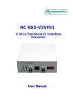
RC 903 V35 FE1
V.35 to Transparent and Fractional E1
Interface Converter
User Manual
Contents
Chapter 1
RC903-V35FE1 (Rev.B) Overview--------------------2
Chapter 2
Connection Configuration ------------------------------4
Chapter 3
Installation & Preparation--------------------------------5
Chapter 4
Dip-switch Setup-------------------------------------------7
Chapter 5
Troubleshooting--------------------------------------------9
1
Chapter 1 RC903-V35FE1 (Rev.B) Overview
1. Descriptions:
RC903-V35FE1 is a standalone interface converter . It provides signal conversion between V.35
and transparent E1 or fractional E1, and can be used for V.35 signal over E1 network transmission.
As growing utilization of E1 resources, many data transmission solutions using E1 link are
accepted by users at large.
RC903- V35FE1 is standalone equipment, with built-in power supply, and can be placed on the
desk.
2. Specifications:
1) E1 interface:
Input impedance:
Interface bit rate:
Line code:
Electrical characteristics:
Frame structure:
Jitter tolerance:
Functions:
2) V.35 interface:
Physical characteristics:
Connector type
Working mode
Interface bit rate
75 Ω unbalanced BNC interface and 120 Ω balanced
RJ-45 interface
2048Kbps±50ppm
HDB3
Complies with ITU-T G.703
Complies with ITU-T G.704
Complies with ITU-T G.823
Complete link alarm indication, Fault Pass Through (FPT) and
auto-reset
Complies with V.35 interface standard
ISO2593 female connector (34 pin female)
DCE
V.35 interface bit rate is N×64Kbps N=1~31 at E1 fractional
pattern;
V.35 interface bit rate is 2048Kbps at E1 transparent pattern
Definition of Indicators
Power (PWR)
Loss of signal (LOS)
On: power is working in good condition
Otherwise: Power faults
OFF: receiving signal in E1 Link
Otherwise: signal loss in E1 link
2
Link error report (LER):
ON: receiving signal error occurs at local E1 link (include
AIS at uplink E1, LOF and CRC4)
OFF: no error occurs
Remote alarm (RAL):
ON: LOS or LER alarm occurs at remote converter
Remote loop-back test (RLP): ON: remote E1 link in loop-back status
Definition of Interface:
E1 interface:
TX BNC connector 75Ω unbalanced interface, E1 signal output
RX BNC connector 75Ω unbalanced interface, E1 signal input
BALANCE RJ-45 connector 120Ω balanced interface, 1 and 2 pin output; 5 and 6 pin input.
The 75Ω unbalanced interface BNC connector is default interface. If balanced interface is
needed, users need manually set dip-switch on the bottom panel.
Definitions of 120Ω balanced interface, BALANCE-RJ45 connector for twisted pair
PIN
1
2
3
Title
TD+
TD-
Not in use
Definition
Output+
Output-
4
5
6
7
RD+
RD-
Not in use
Input+
Input-
8
When 120Ω balanced interface connects with other devices, it is required to make sure the pin
definition of other devices. The pin connection method of twisted-pair on both ends is shown
below:
RC series converter BALANCE-RJ45
E1 transmission device balanced interface
TD
TD
RD
RD
Signal output
Signal output
Signal input
Signal input
Note: When connecting the twisted-pair, TD and TD should be twisted in pairs, and so do RD
and RD.
3
Definition of standard V.35 (DCE) interface:
The left figure shows V.35 interface ISO 2593
connector. Our converter adopts DCE Connector Face
– 34-Pin Female connector, which can be connected
with DTE cable.
The definition of interface is shown below
I — Input O— Output
Pin name
Input/Output
Pin number
Chassis Ground — CGND
-
A
Signal Ground — GND
-
B
Receive Data (A) — RD(A)
O
R
Receive Data (B) — RD(B)
O
T
Receive Timing (A) — RCK(A)
O
V
Receive Timing (B) — RCK(B)
O
X
Send Data (A) — TD(A)
I
P
Send Data (B) — TD(B)
I
S
Send Timing (A) — TCK(A)
O
Y
Send Timing (B) — TCK(B)
O
AA
Terminal Timing (A) — SCTE(A)
I
U
Terminal Timing (B) — SCTE(B)
I
W
Request to Send — RTS
I
C
Clear to Send — CTS
O
D
Data Set Ready — DSR
O
E
Data Carrier Detect — DCD
O
F
Data Terminal Ready — DTR
I
H
4
Chapter 2 Connection Configuration
1. Equipment Interconnection
Interconnection of RC series interface converters must follow the rules shown in the table below.
Otherwise, link disconnection or abnormal data transmission may occur.
Central Office
Customer Premises
RC903-V35FE1
RC903-V35FE1
RC904-V35FE1
RC903-V35FE1
2. Recommended Basic Connection Type
RC903-V35FE1 converter has 3 types of clock working mode
¾ Master Clock Mode: Using built-in crystal-oscillator clock to be system clock, also
called internal clock
¾ Slave Clock Mode: Using clock provided by E1 receiving link to be system clock, also
called restore clock
¾ Terminal Clock Mode: Using Terminal clock provided by DTE equipment to be system
clock
Choosing the clock mode will be done by setting the dip-switch, see chapter 4 for details.
RC903-V35FE1 is used for point-to-point application. The E1 channel can be provided by PDH
SDH equipment, and also can be set up by connecting cables.
1)
Point-to-point fractional E1 mode in “Master clock — Slave clock” structure
(Master clock)
(Slave clock)
As the above figure shows, when connecting Routers or other equipment with V.35 interface using
point-to-point pattern, Routers are required to work at DTE mode. For the convenience of
installation and preparation, users can set Master Clock Mode in local converter and Slave Clock
Mode in remote converter, and the clock source should be in local converter.
When using “Master Clock — Slave Clock” connection structure, if DXC and MUX devices are
connected in series in E1 link, then DXC, MUX and remote converter should be at Slave Clock
Mode (following E1 link clock).
5
2)
Point-to-point fractional E1 mode in “Terminal clock — Slave clock” structure
(Terminal clock)
(Slave clock)
(Clock source)
When remote DTE equipment has to follow the clock phase of local DTE equipment, which is to
say, TX CLOCK of local DTE is internal clock source, users can set Terminal Clock Mode in local
converter, and Slave Clock Mode in remote converter, and must configure clock frequency at V.35
interface of local DTE equipment.
When using “Terminal clock — Slave clock” connection structure, if DXC and MUX devices are
connected in series in E1 link, then DXC, MUX and remote converter should be at Slave Clock
Mode (following E1 link clock).
3)
Point-to-point fractional E1 mode in “Slave clock — Slave clock” structure
(Clock source)
(Slave clock)
(Slave clock)
When using Slave Clock Mode at both sides, it is required to ensure that the clock source is
provided by DXC, MUX or other PCM fractional E1 equipment in the E1 link, and there is only
one clock source in the E1 link.
6
4)
Point-to-point transparent E1 mode in “Master clock — Slave clock” structure or
“Terminal clock — Slave clock” structure
Transparent E1
Transparent E1
(Slave clock)
(Master clock) Clock Source
Transparent E1
Transparent E1
(Slave clock)
(Terminal clock)
(Clock source)
When working in the transparent E1 mode, users need to set Master clock in the converter at one
side and Slave Clock Mode in the converter at the other side. In some special occasions, it is
required to follow V.35 Terminal Clock Mode at one side and Slave Clock Mode at the other side.
Note that the E1 link can only be provided by PDH, SDH or other equipment that provides
transparent E1 channel.
7
5) Extended connection type
In this connection type, the converter is not used in pairs, but connected with equipment of other
manufactures.
If Routers with E1 interface are used at remote side, users are required to first confirm all the
parameters of E1 link, such as fractional/transparent E1, PCM30/31, CRC enable/disable, clock
relations, bandwidth distribution and time slot usage etc. If any one of them does not match the
setting of the converter, there will be problems in connection.
In this case, if devices at both ends work in fractional E1 mode, usually the clock relation is easily
ignored. It is suggested that first make sure which device the clock source is on, then devices at
other end should follow the clock on the E1 link.
3.
Product Compatibility
When connecting RC903-V35FE1 converter with fractional E1 devices of other brands (such as
using V.35 to connect fractional E1 interface converters or Routers etc.), or using DXC and MUX
devices between two converters to work in pairs, it is required to follow the instructions:
1)
2)
3)
4)
5)
PCM30/31 format must be consistent
CRC function enable/disable must be consistent
Data engrossment of V.35 interface in G.704 frame structure must be consistent
Remote bandwidth distribution and remote E1 port loop-back test functions of devices
are disabled
Make sure there is only one clock source in the whole link, the clock mode of all other
PCM devices is in Slave Clock Mode (following E1 link clock).
8
Chapter 3 Installation & Preparation
1. Cautions when the power is on
1)
2)
3)
Hot-swapping V.35 interface is forbidden
It is not advised to hot-swap E1 port
When the power is on and E1 transmitting and receiving links are connected, it is safe to
disconnect or connect one of E1 links. It is suggested that the protecting ground (middle of the
adapter) be connected first when using DC –48V device. Note that inverse connection of
positive and negative polarity is strictly forbidden.
2. Placement
1)
2)
3)
The interface converter should be placed in equipment room, which must be kept clean and
air-conditioned.
Remote converter usually adopts “Slave Clock Mode”.
Local converter usually adopts “Master Clock Mode”. In some special cases, it is required to
follow DTE equipment and adopt “Terminal Clock Mode”.
3. Test of connection
z
z
Make sure that no alarm shows on local equipment
Check if local DTE equipment can process data communication with remote equipment
If the data communication cannot be processed, then test it step by step as follow:
1) Process V.35 port local loop-back test, referring to later part of this manual, introduction to
extended switch setup. If Router indicates success of loop-back test, the V.35 port is proved in
good condition; if Router does not indicate loop-back, first check clock mode, bandwidth
setting of local converter and try to adjust TX CLK and RX CLK phase select switch.
2) After successfully finishing the first step, check if communication in the E1 link works
properly. If converters work in pairs, and No.0 time slot is not blocked in the E1 link, then
remote loop-back test can be processed. If remote E1 port loop-back test is successful, then
local RLP indicator is on, local Router should indicate successful loop-back.
3) If converter does not work in pairs, then it is required to set parameters of E1 interface of other
brand equipment consistent with settings of local converter. Parameters include PCM30/31
format, CRC enable/disable, matching of clock mode etc. After these, please pay attention to
the engrossment of V.35 data in frame structure.
4) After finishing the second step (or make sure the settings of the third step is completely
correct), the communication in the E1 link between local and remote side should be in good
condition. In this case, if remote V.35 interface is connected properly, but it still cannot
communicate properly, please adjust the phase option of TX CLK or RX CLK at remote side.
9
4. Fault-Pass-Through (FPT)
When there is LOS or LER alarm showing in the converter, it indicates that there is a fault in E1
receiving link, and then the DCD signal at V.35 interface will be disconnected.
When there is RAL alarm showing in the converter, it indicates that there is a fault in E1
transmitting link, and then the CTS signal at V.35 interface will be disconnected.
5. Ambience
Operation temperature: 0-45 C
Operation humidity: 5%~90% no condensing
6. Optional AC/DC power supply
AC: 220V/50Hz input ranges from 165 to 265V
DC: -48V input ranges from -36 to -72V
Power consumption: ≤ 3W
7. Dimensions
Dimensions: 120(W)×39(H)×156(D)mm
10
Chapter 4 Dip-switch Setup
1. Definitions of dip-switch setting (frequently used) on front panel
1)
Dip-switch is frequently used on the front panel. It should be
set before use.
1st~5th bit
V.35 interface bandwidth setting
6th bit
Bandwidth active/passive control setting
7th and 8th bit
Clock mode option
2)
OF
ON
1 2 3 4 5 6 7 8
1st ~5th bit: V.35 interface bandwidth setting
V.35 bit rate is N×64Kbps N=1~31 at E1 fractional mode; V.35 bit rate is 2048Kbps at E1
transparent mode. The bit rate setting relationships are shown in the table below. These 5 bits of
dip-switch is actually binary code for setting of N value. When N is set to 0, the converter will
work at E1 transparent mode.
1st bit
2nd bit
3rd bit
4th bit
5th bit
Bandwidth (bps)
0
0
0
0
0
2048K (E1 transparent mode)
0
0
0
0
1
1×64K=64K (Min. bandwidth)
0
0
0
1
0
2×64K=128K
0
0
0
1
1
3×64K=192K
0
0
1
0
0
4×64K=256K
0
0
1
0
1
5×64K=320K
0
0
1
1
0
6×64K=384K
0
0
1
1
1
7×64K=448K
0
1
0
0
0
8×64K=512K
0
1
0
0
1
9×64K=576K
0
1
0
1
0
10×64K=640K
0
1
0
1
1
11×64K=704K
0
1
1
0
0
12×64K=768K
0
1
1
0
1
13×64K=832K
0
1
1
1
0
14×64K=896K
0
1
1
1
1
15×64K=960K
1
0
0
0
0
16×64K=1024K
1
0
0
0
1
17×64K=1088K
1
0
0
1
0
18×64K=1152K
1
0
0
1
1
19×64K=1216K
1
0
1
0
0
20×64K=1280K
1
0
1
0
1
21×64K=1344K
1
0
1
1
0
22×64K=1408K
1
0
1
1
1
23×64K=1472K
1
1
0
0
0
24×64K=1536K
11
1
1
0
0
1
25×64K=1600K
1
1
0
1
0
26×64K=1664K
1
1
0
1
1
27×64K=1728K
1
1
1
0
0
28×64K=1792K
1
1
1
0
1
29×64K=1856K
1
1
1
1
0
30×64K=1920K(Max. bandwidth 1)
1
1
1
1
1
31×64K=1984K(Max. bandwidth 2)
In the table above, symbol “1” means OFF, and symbol “0” means ON. For example, 384Kbps
bandwidth setting should be “00110”, then the dip-switch should be set to “ON, ON, OFF, OFF,
ON”. It is suggested that you copy down the binary codes corresponding to the desired bandwidth,
then set OFF for symbol “1” and ON for symbol “0”.
Note A: Bandwidth distribution at both local and remote ends must be the same
“Max. Bandwidth 1 ” is the maximum bandwidth allowed under condition of PCM30
“Max. Bandwidth 2 ” is the maximum bandwidth allowed under condition of PCM31
3)
6th bit: V.35 bandwidth control option
6th bit
Bandwidth control
OFF
Active bandwidth control
ON
Passive bandwidth control
To implement the function that the remote device follows local device bandwidth setting, it is
required to follow the instructions below:
1.
RC903-V35FE1 devices work in pairs as point-to-point connection (or work with other
equipment with N×64K V.35 interface)
2. Do not connect in series with PCM equipment (such us DXC MUX) that engrosses No.0
time slot in the E1 link.
3. Do not set equipment to transparent mode (N=0) at both sides.
When all the conditions above are satisfied, you can set a device to active bandwidth control at one
side, and passive bandwidth control at the other side. The first 5 bits of bandwidth setting switch at
passive bandwidth control side cannot be set to transparent mode (N=0). It is suggested that all of
them be set to OFF. When the E1 link is connected, the actual bandwidth of passive side is the same
as the setting of active side.
The 6th bit of dip-switch has nothing to do with the clock mode setting, so users can either choose
active bandwidth control at Master clock side, or at Slave clock side. Most users are accustomed to
choose active bandwidth control at Master clock side.
If any one of conditions above cannot be satisfied, then the 6th bit of dip-switches of converters at
both sides must be set to active bandwidth control status, and the actual bandwidth can be set by the
first five bits. Note that especially when N=0, i.e. at transparent mode, the 6th bit should be set to
active bandwidth control at both sides.
12
When setting loop-back test by the switch on the bottom panel, the definition of the 6th bit changes
to loop-back type option.
6th bit
After setting of loop-back, choose loop-back type
OFF
Remote E1port loop-back
ON
Local V.35 port loop-back
Please see the definition of the 5th bit of switch on the bottom panel for content of loop-back test.
4)
7th and 8th bit: clock mode option
7th bit
8th bit
Clock mode option
OFF
OFF
Master Clock Mode (Internal clock)
OFF
ON
V.35 Terminal Clock Mode
ON
OFF
Not in use
ON
ON
Slave Clock Mode (following E1 link clock)
Choose the clock mode that is suitable for your application according to connection method in
Chapter 2. The V.35 DTE interface of Router should be set as: both Tx Clock and Rx Clock
External at the connected V.35 interface in Master and slave Clock Mode, i.e. the default status; Tx
Clock Internal Rx Clock External at connected V.35 interface in Terminal Clock Mode.
5)
The factory default dip-switch settings on front panel: all OFF
Dip-switch
1st bit
2nd bit
3rd bit
4th bit
5th bit
6th bit
7th bit
8th bit
Default
OFF
OFF
OFF
OFF
OFF
OFF
OFF
OFF
Meaning
N=31 V.35 bandwidth 1984K
Active
bandwidth
control
Master Clock
Mode
2. Definitions of dip-switch (extended setting) on the bottom panel
There is also a not-frequenty-used dip-switch on the bottom panel.
ON
Note that the main difference between this dip-switch and the one on front
panel is: the “lower position” is ON in the dip-switch on front panel, but the
OF
“upper position” is ON in the dip-switch on bottom panel.
1 2 3 4 5 6 7 8
1) Definitions of 1st ~ 5th bit
1st bit
2nd bit
3rd bit
4th bit
5th bit
TX CLK phase
RX CLK phase
PCM30/31 option
CRC function
option
Loop-back test
switch
ON
Negative
Negative
PCM30 effective
Disabled
Loop-back test
OFF
Positive
Positive
PCM31 effective
Enabled
Normal work
Definition
z
TX CLK and RX CLK phase option is for differences of phase relationships of V.35 interface
clock and data according to different branded Routers. When both TX CLK and RX CLK are
set as positive, the test at V.35 synchronous WAN port of Cisco series Routers is success.
13
TX CLK positive: sampling TD signal at TCK clock falling edge
TX CLK negative: sampling TD signal at TCK clock rising edge
RX CLK positive: transmitting RD signal at RCK clock falling edge
RX CLK negative: transmitting RD signal at RCK clock rising edge
z
PCM30/31 option is for that when other equipment (e.g. DXC and MUX) in E1 channel
requires frame structure to be PCM30, then the converter should be set PCM30 effective (N≤
30); when PCM31 is required, the converter should be set PCM31 effective (N≤31). The
settings of this bit of switches must be consistent at both local and remote ends.
z
CRC option is used to set “enable” or “disable” CRC function according to requirement of the
channel. The settings of this bit of switched must be consistent at both local and remote ends.
z
Loop-back test function is an auxiliary function for users to test equipment and links. When
loop-back function has been set, the loop-back type can be chosen by the 6th bit of dip-switch
on the front panel.
DTE or V.35 bit
Local converter
V.35
error tester
Master clock
E1Channel
Remote converter
Slave clock
Following conditions have to be met for remote E1 loop-back test:
1. RC903-V35FE1 devices work in pairs as point-to-point connection (or work with other
equipment with N×64K V.35 interfaces)
2. Do not connect in series with PCM equipment (such as DXC and MUX) that engrosses
No.0 time slot in the E1 link
3. Do not set equipment to transparent mode (N=0) on both sides.
4. Only be used on the converters set in “Master Clock Mode” and “Terminal Clock Mode”.
As the above figure shows, after all above conditions satisfied, users can set Master or Terminal
Clock Mode on local converter and set the 5th bit of bottom dip-switch to ON and the 6th bit of
front dip-switch to OFF to process remote E1 loop-back test. If E1 link is in good connection, local
RLP will be lightened, which indicates remote E1 interface loop-back successful. Users can enquire
the status of local Router port, thus the loop-back status will be displayed.
DTE or V.35 bit
Local converter
V.35
error tester
Master clock
E1Channel
The local V.35 interface loop-back test only takes place on the converters set to “Master Clock
Mode” and “Terminal Clock Mode”. As the above figure shows, users can set Master or Terminal
Clock Mode on local converter and set the 5th bit of bottom dip-switch to ON, the 6th bit of front
dip-switch to OFF and set the first five bits of dip-switch to the bandwidth required to process local
V.35 loop-back test. Users can enquire the status of local Router port, thus the loop-back status will
14
be displayed. Local V.35 interface loop-back test is usually used to check if V.35 cable is properly
connected, or Router port starts working, or the phase relationships of clock and data signals
between the converter and Router is consistent.
As mentioned in previous text, the 6th bit of dip-switch on front panel is defined as bandwidth
active/passive control option when works in normal mode; it is defined as remote/local loop-back
option when doing loop-back test. When the converter is set to local loop-back status, the local
bandwidth will be automatically set to Active Bandwidth Control. In this case, it will not be
affected by the 6th bit of dip-switch on front panel.
2) The 6th~8th bit of dip-switch: E1 interface type option
75Ω BNC unbalanced interface effective
6th bit
7th bit
ON
ON
8th bit
120Ω RJ-45 balanced interface effective
Or
6th bit
7th bit
8th bit
ON
OFF
OFF
OFF
Note: The settings above must be strictly followed; otherwise, E1 interface will be abnormal.
3) The factory default settings on the bottom panel
Dip-switch
position
1st bit
2nd bit
3rd bit
4th bit
5th bit
6th bit
7th bit
8th bit
Status
OFF
OFF
OFF
OFF
OFF
ON
ON
OFF
Definition
TX CLK
positive
RX CLK
positive
PCM31
CRC
Enable
No
loop-back
15
75Ω BNC interface
effective
Chapter 5 Troubleshooting
If there are any problems during installation and operation, please try to solve them according to the
following suggestions. If the problems still exist, please contact distributors for help.
z Power (PWR): indicator OFF
Answer Please check if there is any fault with power supply.
z Loss-of-Signal (LOS) alarm in E1 link: indicator ON
Answer: LOS alarm caution that your E1 interface cannot receive signal. Please check if the input
cable is properly connected. If using 120Ω twisted-pair interface, please check if the line sequence
is correct. Please also check if transmitting and receiving cables are reversely connected, and avoid
hot swapping. Process local loop-back test, if there is still alarm, thus it indicates that the E1
interface of converter has been damaged.
z E1 receiving signal error alarm (LER): indicator ON
Answer: LER alarm may be caused by the uplink E1 link alarm (AIS), loss of frame (LOF) or
cyclic redundancy check (CRC). This indicates that there are errors in E1 receiving link. Please
check the of E1 receiving link and E1 frame parameter of equipment on opposite site, such as
PCM30/31 and CRC enable/disable.
z Remote alarm (RAL): indicator ON
Answer: RAL at local end caused by LOS or LER at remote (opposite) end equipment. This
indicates that there is error at E1 receiving link of remote equipment, i.e. transmitting link of local
equipment.
z Severe packet loss of DTE equipment
Answer: The possible reasons for severe packet loss are.
1. Incorrect clock mode setting.
2. Check V.35 interface status of the Router, if there are data errors of input and output, then it
indicates that TX CLKand RX CLK phase relationship need to be adjusted. This problem can
be located by doing local V.35 interface loop-back test.
3. Cable loose at E1 port or wrong line sequence.
z
Connecting with DTE equipment in transparent mode, there are few packet losses occurring
when using default phase.
Answer: It is needed to adjust the phase. Normally you only need to adjust the 1st bit of dip-switch,
i.e. adjust TX CLK from positive (deault) to negative.
z Compatibility with equipment of other brands
Answer: RC903-V35FE1 can cooperate with similar products of other brands, and also can
cooperate with Routers with fractional E1 interface. It is needed to ensure they are using same time
16
slot engrossment and same setting of PCM30/31 and CRC. However, Passive Bandwidth Control
function and E1 loop-back test of remote converter cannot be used.
z Compatibility with other V.35 products
Answer: RC903-V35FE1 and RC904-V35FE1 can cooperate with other products that have similar
functions, such as followings:
1. SUBM-FV35, N x 64K V.35 interface module, can be installed in RC800-240B series standalone
PDH fiber-optic multiplexer.
2. RC800-30B-FV35, N x 64K V.35 interface PDH fiber-optic multiplexer, equipped with all the
functions of RC903-V35FE1 and RC800-30B single E1 PDH fiber-optic multiplexer.
ORDERING INFO
RC 903 - V35FE1: Standalone, V.35 to transparent or
fractional E1 interface converter, AC 115V or 230V/DC-48V
17