1
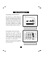
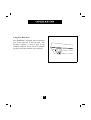
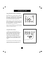
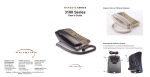
MARQUIS 9000MWD SINGLE LINE CORDLESS HOTEL TELEPHONE Congratulations on the purchase of your TeleMatrix MarquisTM 9000MWD telephone.The 9000MWD includes advanced features suitable for use in hotel/motel guest room environment. TeleMatrix has designed the telephone to be simple to install and easy to use. Cordless performance provides convenience and mobility for all your guest rooms. Your 9000MWD telephone is a precision electronic device that requires minimum maintenance. Please be sure to read the contents set forth in the user’s guide to become familiar with the wiring and functionality of this product. 2 CAUTION To reduce the risk of fire or injury, read and follow these instructions: 1. Use only the designated battery pack for cordless handset and power adapter for the base. 2. Do not dispose of the battery(ies)in a fire. The cell may explode. Check with the local codes for possible special disposal instructions. 3. Do not open or mutilate the battery(ies). Released electrolyte is corrosive and may cause damage to the eyes or skin. It may be toxic if swallowed. 4. Exercise care in handling batteries in order not to short the battery with conducting materials such as rings, bracelets and keys. The battery or conductor may overheat and cause burns. 5. Do not attempt to recharge the battery(ies) provided with or identified for use with this product. The batteries may leak corrosive electrolyte or explode. 6. Do not attempt to rejuvenate the battery(ies) provided with or identified for use with this product by heating them. Sudden release of the battery electrolyte may occur causing burns or irritation to the eyes or skin. 7. When replacing the batteries, all batteries should be replaced at the same time. Mixing fresh and discharged batteries could increase internal cell pressure and rupture the discharged battery(ies). (Applies to products employing more than one separately replaceable primary battery). 8. When inserting batteries into this product, the proper polarity or direction must be observed. Reverse insertion of batteries can cause charging, and that may result in leakage or explosion (applies to product employing more than one separately replaceable primary battery). 9. Remove the batteries from this product if the product will not be used for a long period of time (several months or more) since during this time the battery could leak in the product. 10. Discard dead batteries as soon as possible since dead batteries are more likely to leak in a product. 11. Do not store this product, or the batteries provide with or identified for use with this product in h i g h temperature areas. Batteries that are stored in a freezer or refrigerator for the purpose of extending the shelf life should be protected from condensation during storage and defrosting. Batteries should be stabilized at room temperature prior to use after cold storage. 3 IMPORTANT SAFETY INSTRUCTIONS When using your telephone equipment, basic safety precautions should always be followed to reduce the risk of fire, electric shock and injury to persons, including the following: 1. Read and understand all instructions. 2. Follow all warnings and instructions marked on the product. 3. Unplug this product from the wall outlet before cleaning. Do not use liquid cleaners or aerosol cleaners. Use a damp cloth for cleaning. 4. Do not use this product near water, for example, near a bath tub, wash bowl, kitchen sink, or laundry tub, in a wet basement, or near a swimming pool. 5. Do not place this product on an unstable cart, stand, or table. The product may fall, causing serious damage to the product. 6. Slots and openings in the cabinet and the back or bottom are provided for ventilation, to protect it from overheating, these openings must not be blocked or covered. The openings should never be blocked by placing the product on the bed, sofa, rug, or other similar surface. This product should never be placed near or over a radiator or heat register. This product should not be placed in a built-in installation unless proper ventilation is provided. IF UNIT IS EQUIPPED WITH POWER ADAPTER: 7. This product should be operated only from the type of power source indicated on the marking label. If you are not sure of the type of power supply to your home, consult your dealer or local power company. IF ADAPTER IS PROVIDED WITH A GROUNDED TYPE ATTACHMENT PLUG: 8. This product is equipped with a three wire grounding type plug, a plug having a third (grounding) pin. This plug will only fit into a grounding type power outlet. This is a safety feature. If you are unable to insert the plug into the outlet, contact your electrician to replace your obsolete outlet. Do not defeat the safety purpose of the grounding type plug. IF ADAPTER IS PROVIDED WITH A POLARIZED ATTACHMENT PLUG: This product is equipped with a polarized line plug (a plug having one blade wider than the other). This plug will fit into the power outlet only one way. This is a safety feature. If you are unable to inset the plug fully into the outlet, try reversing the plug. If the plug should still not fit, contact your electrician to replace your obsolete outlet. Do not defeat the safety purpose of the polarized plug. 9. Do not allow anything to rest on the power cord. Do not locate this product where the cord will be abused by persons walking on it. 10. Do not overload wall outlets and extension cords as this can result in the risk of fire or electric shock. 11. Never push objects of any kind into this product through cabinet slots as they may touch dangerous voltage points or short out parts that could result in a risk of fire or electric shock. Never spill liquid of any kind on the product. 12. To reduce the risk of electric shock, do not disassemble this product, but take it to a qualified serviceman when some service or repair work is required. Opening or removing covers may expose you to dangerous voltages or other risks. Incorrect re-assembly can cause electric shock when the appliance is subsequently used. 13. Unplug this product from the wall outlet and refer servicing to qualified service personnel under the following conditions: A. When the power supply cord or plug is damaged or frayed. B. If liquid has been spilled into the product. C. If the product has been exposed to rain or water. D. If the product does not operate normally by following the operating instructions. Adjust only those controls, that are covered by the operating instructions because improper adjustment of other controls may result in damage and will often require extensive work by a qualified technician to restore the product to normal operation. E. If the product has been dropped or the cabinet has been damaged. F. If the product exhibits a distinct change in performance. 14. Avoid using a telephone (other than a cordless type) during an electrical storm. There may be a remote risk of electrical shock from lightning. 15. Do not use the telephone to report a gas leak in the vicinity of the leak. SAVE THESE INSTRUCTIONS FCC Part 15 Compliance Warning: Changes or modifications to this unit not expressly approved by the party responsible for compliance could void the user's authority to operate the equipment. NOTE: This equipment has been tested and found to comply with the limits for Class B digital device, pursuant to Part 15 of the FCC Rules, These limits are designed to provide reasonable protection against harmful interference in a residential installation. This equipment generates, uses, and, can radiate radio frequency energy and, if not installed and used in accordance with the instructions, may cause harmful interference to radio communications. However, there is no guarantee that interference will not occur in a particular installation. If this equipment does cause harmful interference to radio or television reception, which can be determined by turning the equipment off and on, the user is encouraged to try to correct the interference by one or more of the following measures: • • • • Reorient or relocate the receiving antenna. Increase the separation between the equipment and receiver. Connect the equipment into an outlet on a circuit different from that to which the receiver is connected. Consult the dealer or an experienced radio TV technician for help. Canadian Emissions Compliance "This digital apparatus does not exceed the Class B limits for radio noise emissions from digital apparatus set out in the Radio Interference Regulations of the Canadian Department of Communications. " 5 DOC - NOTICE AND LOAD NUMBER STATEMENT NOTICE: The Canadian Department of Communications label identifies certified equipment. This certification means that the equipment meets certain telecommunications network protective, operational and safety requirements. The Department does not guarantee the equipment will operate to the user's satisfaction. Before installing this equipment, users should ensure that it is permissible to be connected to the facilities of the local telecommunications company. The equipment must also be installed using an acceptable method of connection. In some cases, the company's inside wiring associated with a single line individual service may be extended by means of a certified connector assembly (telephone extension cord). The customer should be aware that compliance with the above conditions may not prevent degradation of service in some situations. Repairs to certified equipment should be made by an authorized Canadian maintenance facility designated by the supplier. Any repairs or alterations made by the user to this equipment, or equipment malfunctions, may give the telecommunications company cause to request the user to disconnect the equipment. Users should ensure for their own protection that the electrical ground connections of the power utility, telephone lines and internal metallic water pipe system, if present, are connected together. This precaution may be particularly important in rural areas. Caution: Users should not attempt to make such connections themselves, but should contact the appropriate electric inspection authority, or electrician, as appropriate. The Load Number (LN) assigned to each terminal device denotes the percentage of the total load to be connected to a telephone loop, which is used by the device, to prevent overloading. The termination on a loop may consist of any combination of devices subject only to the requirement that the total of the Load Numbers of all the devices does not exceed 100. An alphabetic suffix is also specified in the Load Number for the appropriate ringing type (A or B), if applicable. For example, LN = 20 A designates a Load Number of 20 and an "A" type ringer. 6 NOTIFICATION TO THE TELEPHONE COMPANY Before you may connect your telephone you must notify the telephone company of particular line(s) to which such connections is to be made, and provided to the telephone company the FCC registration number and ringer equivalence number of the registered protective circuitry. The customer shall give notice to the telephone company upon final disconnection of such equipment or circuitry from the particular line(s). MALFUNCTION OF TELEPHONE In the event that your telephone fails to work properly during your ownership and use of it, you should disconnect it from the telephone line to determine if it is your phone, which is not working properly, or if it is problem in the telephone company's network. If the problem is with your telephone you should discontinue its use until it is repaired. TELEPHONE CONNECTION REQUIREMENTS Except for telephone company- provided ringers, all connections to the telephone network shall be made through standard telephone company provided jacks, in such a manner to allow for easy and immediate disconnection of the terminal equipment. Standard jacks shall be so arranged that if the plug connected thereto is withdrawn, no interference to the operation of the equipment at the customer's premises which remains connected to the telephone net work shall occur by reason of such withdrawal. These telephones may not be used on party lines or coin operated lines. CHANGES IN TELEPHONE COMPANY EQUIPMENT OR FACILITIES The telephone company is entitled to make changes in its facilities equipment, operations, and procedures. Should these changes be expected to render your terminal equipment incompatible with the telephone company's facilities you will be given sufficient notice to allow you to make the necessary modification to your terminal equipment without any interruption of your service. 7 Consumer Information: This equipment complies with Part 68 of the FCC rules and the requirements adopted by the ACTA. On the bottom of this equipment is a label that contains, among other information, a product identifier in the format US:2N3WI29B95339 If requested, this number must be provided to the telephone company. An applicable certification jacks Universal Service Order Codes (USOC) for the equipment is provided (i.e., RJ11C) in the packaging with each piece of approved terminal equipment. A plug and jack used to connect this equipment to the premises wiring and telephone network must comply with the applicable FCC Part 68 rules and requirements adopted by the ACTA. A compliant telephone cord and modular plug is provided with this product. It is designed to be connected to a compatible modular jack that is also compliant. See installation instructions for details. The REN is used to determine the number of devices that may be connected to a telephone line. Excessive RENs on a telephone line may result in the devices not ringing in response to an incoming call. In most but not all areas, the sum of RENs should not exceed five (5.0). To be certain of the number of devices that may be connected to a line, as determined by the total RENs, contact the local telephone company. [For products approved after July 23, 2001, the REN for this product is part of the product identifier that has the format US:2N3WI29B95339 The digits represented by 29 are the REN without a decimal point (e.g., 29 is a REN of 2.9). For earlier products, the REN is separately shown on the label.] If this equipment 95339/953391 causes harm to the telephone network, the telephone company will notify you in advance that temporary discontinuance of service may be required. But if advance notice isn't practical, the telephone company will notify the customer as soon as possible. Also, you will be advised of your right to file a complaint with the FCC if you believe it is necessary. The telephone company may make changes in its facilities, equipment, operations or procedures that could affect the operation of the equipment. If this happens the telephone company will provide advance notice in order for you to make necessary modifications to maintain uninterrupted service. Please follow instructions for repairing if any (e.g. battery replacement section); otherwise do not alternate or repair any parts of device except specified. Connection to party line service is subject to state tariffs. Contact the state public utility commission, public service commission or corporation commission for information. This equipment is hearing aid compatible. NOTICE: If your home has specially wired alarm equipment connected to the telephone line, ensure the installation of this [equipment ID] does not disable your alarm equipment. If you have questions about what will disable alarm equipment, consult your telephone company or a qualified installer. Should you experience trouble with this equipment, please contact (TeleMatrix, Inc.Customer Care Center 5025 Galley Road Colorado Springs, CO. 80915 . Toll Free:1-800-462-9446 Direct:719-638-8821 Fax:719-638-8815 www.telematrixusa.com) for repair or warranty information. If the equipment is causing harm to the telephone network, the telephone company may request that you disconnect the equipment until the problem is resolved. [NOTICE: According to telephone company reports, AC electrical surges, typically resulting from lightning strikes, are very destructive to telephone equipment connected to AC power sources. To minimize damage from these types of surges, a surge arrestor is recommended.] 8 Features .........................................................…………………........................ 8 Controls .............…..............………………….................................................. 9 Installation …………………............................................................................. 15 Wall Mounting .....…..............................................…………………................ 16 Battery Preparation ......................………………….......................................... 17 Switch Settings .…………………..…............................................................... 21 Programming ..........….........................................………………….................. 22 Operation .................…........................................................…………………. 25 Service ......................…........................................…………………................ 33 Warranty .....................…............………………….......................................... 34 Spare Part List ……………………………………………...………………… 35 9 • One Line Operation • Cordless Handset, 900 Mhz Operation, with Handshake Technology • Long Life Rechargeable NiCd Battery • Speakerphone with volume control • 10 Guest Service Keys (Speed Dial Locations) • TouchLiteTM Message Waiting Indicator/Retrieval Feature • Convenient Data Port • “Soft-Key” Volume Control (Handset -- 8 step/ADA Compliant) • HI/Low Ringer Volume Controls (Handset) • Speaker Volume Control Rocker Switch • Line Status Indicators (In-Use/Hold/Mute/Ringing) • Mute Key (Base) • Redial/Pause Key (submerged) • Flash Key (submerged) • Handset Locator Key (On Base) • Charge Light Indicator • Extended Memory Back-up (Lithium Battery) • Desk Or Wall Mountable • Operates Behind 24/48 Volt Systems • Hearing Aid Compatible 10 TOP VIEW (14) (13) (11) (10) (1) NEON LED STORE FLASH (12) FOR MESSAGES 1 2 ABC (9) 3 DEF PRESS HERE 4 GHI 7 PQRS * 5 JKL 6 (8) MNO REDIAL 8 (7) 9 TUV WXYZ 0 # (6) (3) MUTE SPEAKER (5) (4) (2) 11 BASE UNIT 1. Handset ..........……………………..….....…...…... Hearing aid compatible, low profile styling. 2. Charge LED …….……………………………….. Indicator that lights when the handset is charging. 3. In-Use / Ringer Indicator ………………………... Indicator shows line ringing, line in use 4. Mute Key ………………………………………… Used to mute base micphone. LED indicator shows when Mute is in use. 5. Speaker Key ……………………………………… Used to activate speaker mode. LED indicator shows when Speaker is in use. 6. Speakerphone Volume Control Rocker Switch ….. Used to control the loudness of the speakerphone. 7. Locate Key ………………………...……………... Used to locate the handset unit. 8. Pause/Redial Key ....………..........………….….… Submerged key used to program pause into speed dial memory or used to dial the last number dialed 9. TouchLiteTM One Touch Message Retrieval Key… Combination visual message waiting lamp & speed dial key used for message retrieval. LED indicator will blink indicating a new message in the user’s voice mail box (user must subscribe to a messaging system). 10. Flash Key ........…….…...............…………………. Submerged key used to program a flash timing into speed dial memory. 11. Store Key ...……….………….......….................…. Submerged key used to program speed dial keys. 12. Guest Service Keys (Speed Dial) ……………….… 10 programmable speed dial keys used for one-touch access to hotel guest services. 13. Neon 90V / LED Switch …………………………. Used to select 90 Volt Neon or low voltage LED operation for Message Waiting. 14. Antenna …………………………………………... Used to communicate with the handset. 11 TOP VIEW OF HANDSET (10) HI (2) (8) LOW RINGER (1) (3) ON/OFF 1 4 GHI 7 (5) HOLD 2 3 ABC DEF 5 JKL 8 6 MNO 9 PQRS TUV WXYZ * 0 # REDIAL VOLUME (4) FLASH (7) (6) 13 (9) HANDSET UNIT 1. Handset ..........…………...........…………….... Hearing aid compatible, low profile styling. 2. ON/OFF Line Key ...............……………..…... Used to activate line or hold. 3. Hold Key ........................……………......…... 4. Numeric Dialing Keypad ……………………. Used to dial numbers. 5. Redial Key ………………………….……….. 6. Handset Volume Control ………………….… Used to increase or decrease volume 7. Flash Key ........………............…………….... Provides a 600mS timed line break. 8. Handset Ringer HI/LOW Control Switch …... Used to control the loudness of the handset ring. 9. Handset to Base Connection ………………..... Charges the battery when placed into the cradle and connected to the base. 10. Antenna …………………………………………... 14 Used to place call on hold. Used to dial the last number dialed. Used to communicate with the base unit. TOP SIDE (1) LEFT SIDE DATA (2) 15 1. Telephone Jack …………...................... Modular receptacle for plugging in telephone line. 2. Data Port …………..………........…...... Convenient port to connect a computer modem, fax or answering device. 16 Caution • Never install telephone wiring during a lightning storm. • Never install telephone jacks in wet locations unless the jack is specifically designed for wet locations. • Never touch uninstalled telephone wires or terminals unless the telephone line has been disconnected at the network interface. • Use caution when installing or modifying telephone lines. Parts Check List 5 The following parts are included with the 9000MWD: 1 L I N E L1+L2 1. Stationary Base Unit. NEO N LED STORE FLASH L2 2 3 FOR ME SSAGES 1 2 A BC 3 D EF PRESS HERE 4 5 GH I JKL 7 8 6 MN O REDIAL PQR S 2. Mobile Handset Unit. * 9 TUV WXY Z 0 # OPER MUTE 6 3. 15’ Modular Telephone Line Cord. 4 4. 15’ Modular Line Cord 5. Handset Battery Pack. 6. Power Adapter. 17 S PEAKE R Wall Mounting Your Telephone* The 9000MWD is designed to be conveniently wall mounted. Note: A 9000MWD wall mounting kit must be used (not included) Follow these easy steps: 1. The handset retaining clip must be engaged to secure the handset when hanging up. To engage the clip, unsnap the clip, rotate the clip 180º and then snap the clip into place. 2. A separate wall mount wedge kit is needed for this installation. This wedge will allow the telephone to be at the correct angle when wall mounted. To install the wedge for wall mounting, snap into place. * The wall mount wedge can be ordered separately. See the Parts List in the back of this manual. 18 Power Adapter “LINE” Connection The power adapter “LINE” connection is used to connect the telephone lines from the wall jack to the telephone. L I N E P H O N E L1+L2 OUT L2 Using the 15’ modular telephone line cord provided, connect one end of the cord to the RJ14 telephone jack on the wall or base board. The remaining end of the cord plugs into the “L1+L2” jack side of the power adapter. Power Adapter “PHONE” Connection The power adapter “PHONE” connection is used to provide both the telephone line and the power source to the telephone. P H O N E Using the 15’ modular telephone line cord provided, plug one end of the line cord into the back of the telephone. Plug the remaining end into the power adapter jack labeled “PHONE”. OUT 120V AC Power IMPORTANT! The telephone will not function if the line cord connections are not properly inserted into the correct jack. Be sure that the telephone line cord connections are not reversed. (“LINE”/”PHONE”). 19 Install the Handset Battery To install the handset battery; 1. Open the battery cover as shown, 2. Insert the battery pack. Match the polarity marks from the battery to the case (+ to +). 3. When properly installed, the battery will slide into position. DO NOT FORCE THE BATTERY. Be sure the contacts are centered and the battery tab is placed into the tab slot. Note: if the battery does not seem to fit, turn the battery on the opposite side and re-insert. 4. Replace the battery cover by inserting the open end of the cover into the handset and pressing the back into place. Removing the Handset Battery and Battery Cover Battery Cover Removal 2. Grip Here 3. Press Down Center 4. Slide Downward 1. Insert small screwdriver and lift upward to release cover Battery Placement Tab Must Be Placed Into Housing Slot 1. Insert a small screwdriver into bottom slot. Lift the cover by lifting the screwdriver. Do not lift the cover more that 1/2”. 2. Grip the handset tightly on the sides. 3. Depress the cover where the top portion of the battery cover (middle of the handset base) meets the handset. This will release the battery cover lock. DO NOT LIFT MORE THAN 1.2” UPWARD 4. Slide the cover downward and remove. 20 Message Waiting Lamp The 9000MWD supports a low-voltage LED message waiting lamp or 90VDC neon. To turn ON, slide the switch to the “LED” or “NEON” position. The switch is located underneath the overlay and faceplate on the top of the base. Note: The 9000MWD is factory preset to the “Neon” setting. ! *NOTE: Voice Mail will ONLY operate if you subscribe to your local telephone company voice mail service and/or if your PBX telephone system is equipped with this technology. These telephone features will not work unless you are a subscriber. 20 Guest Service Keys (Speed Dial Memory) The 9000MWD has 10 one-touch speed dial memory locations that are used as a convenience for dialing frequently used numbers. Each speed dial memory location can store up to 32 digits. Step: Procedure: 1. Press the Speakerphone ON/OFF key to activate the phone. 2. Locate the Store key under the plastic overlay on the top housing. Press the “Store” key. 3. Dial the digits using the numeric dial pad (example: 1 2 3 4 5 6). 4. Press the desired speed dial location (1 through 5 or 10, plus the message waiting lamp) where the memory is to be saved. ____________________________________________ To program additional numbers, repeat steps 3 thru 4. ____________________________________________ 22 Note: To program Speed Dial into the telephones memory, the line cord must be plugged into the power adapter and the telephone line cord must be plugged into the wall jack. The Speaker key must be activated. The TouchLiteTM Feature TouchLiteTM is a patent-pending new innovation that integrates the visual message waiting lamp and a speed dial memory key into one function. It allows easy-access for guests to retrieve voice mail or front desk messages. When the red message waiting lamp lights to notify a guest that a message is waiting, a simple press of the red TouchLiteTM connects the guest to the message center or the front desk. Note: The TouchLiteTM key adds an additional memory location to your 9000MWD telephone. Programming The TouchLiteTM See “Programming: Guest Service Keys (speed dial memory)” ! *NOTE: Voice Mail will ONLY operate if you subscribe to your local telephone company voice mail system and/or if your PBX telephone system is equipped with this technology. These telephone features will not work unless you are a subscriber. 22 Programming A Flash Into Memory The “Flash” key is a storable function into memory that is used to provide a 600mS timed line break. This function may be required for accessing line features provided by your telephone system or local telephone company. For example, many times the “Flash” is used to access line features such as “call waiting”, “call transfer”, “Call pick-up”, etc. Contact your system coordinator or local telephone company regarding special line features that you may have where a Flash key is needed. Note: the “Flash” function counts as 1 digit when stored into a speed dial memory location Programming A Pause Into Memory The “Pause” key is used to program a 3 second delay into memory. A speed dial number may need to pause during its dialing sequence to insure proper connections. For example, some telephone systems require that a ‘9’ be dialed to access an outside telephone line. In this case, a pause should be stored after the digit ‘9’ for timing purposes. When in the store mode, press the REDIAL/ PAUSE key (submerged) to store a pause into the program memory. 24 Note: the “Pause” function counts as 1 digit when stored into a speed dial memory location Placing A Call Using The Handset Follow the instructions below for placing a call using the handset. 1. Lift the handset from the base and press the ON/OFF key to activate the line. 2. Dial out by using the numeric dial pad on the handset. To reach guest services, line one on handset can be activate. Press the speed dial key on the base unit. 3. To end the call, simply replace the handset back on the cradle, or press the line key again. 25 BASE UNIT DIALING Placing A Call Using The Base Unit Follow the instructions below for placing a call using the base unit. 1. The handset can either be on or off the base cradle when dialing from the base unit. 2. Press the SPEAKER key to activate. 3. Dial out by using the numeric dial pad on the base unit. 4. To end the call, simply press the Speaker key. 26 Locating The Handset The 9000MWD is equipped with a handset locator feature key located on the base. Simply press the “LOCATE” button on the base unit. The handset will beep for about 15 seconds. Once the handset is located, simply press the ON/OFF key to activate your handset. Technology Feature: Frequency Range Limitation The 9000MWD cordless phone comes with a special Frequency Range Limitation of 200 feet within the design of the phone. This feature is designed specifically the hotel and lodging industry to provide clarity and security. 27 Using The Handset Volume Control A convenient handset volume control is provided. This volume control will adjust the loudness of the handset. The loudness can be adjusted in seven (8) steps up or down. Using The Speakerphone Volume Control A rocker volume switch is provided to adjust the loudness of the speakerphone. Simply press the upper part of the rocker switch to increase the volume or press the lower part of the rocker switch to lower the volume. The loudness can be adjusted in eight (8) steps up or down. 28 Line Status Indicators (Base Unit) Line Status Indicators (Handset Unit) The 9000MWD has visual LED indicators located on the base unit that indicates the status of the telephone. The 9000MWD has visual LED indicators located on the handset that indicates the status of the telephone. Ringing of Line The in use LED blinks rapidly GREEN to show ring. Ringing of Line The LED above the line key blinks rapidly RED to show ring. Line In-Use The in use LED shows a steady GREEN color when base in off-hook. When handset in use , the in use in use LED on the base unit blink slowly. Line In-Use The LED above the line key shows a steady RED color when off-hook. Line Mute The LED above the MUTE key is a steady RED when the “Mute” key is active. 29 Using The Data Port The 9000MWD is equipped with a convenient port on the right side of the base unit. This modular receptacle is used to plug in any standard telephone device such as a computer modem, answering machine or fax machine. 30 Using The Hold Feature (on Handset) The “Hold” key is used to place a caller on hold. To use, simply press the “Hold” key on the handset. The LED light on the handset will indicate that the line is on hold and the base unit LED will blink rapidly Green. When placing a caller on hold, the line will not be disconnected. To return to the caller, press the “ON/OFF” key on the handset or the “SPEAKER” key on the base. Note: Pressing the SPEAKER key on the base when the handset is on hold will activate the base unit. The handset will stay on hold until released. Using The Mute Feature A “Mute” key is provided to allow for privacy during a background conversation. When the “Mute” key is activated, the microphone in the speakerphone within the base becomes disabled. When the “Mute” feature is activated, the caller will not hear your voice. The “Mute” key will illuminate to show that the feature is activated. To de-activate, press the “Mute” key again. The MUTE feature only works on the base unit. The handset does not mute out when MUTE is active. 31 Redial (On Handset) The “Redial” key is used to automatically redial the last number that was manually dialed from the numeric dial pad of the specific handset or base unit. To use (handset): • • • • Lift the handset Press ON/OFF key. Press the “Redial” key. The number that was last dialed on the handset will automatically redial. 32 When problems arise during installation or service that cannot be resolved using this or related documents, contact the TeleMatrix Technical Service department 8:30a.m. - 4:30p.m. MST: Toll Free: Direct: Fax: Web Site: 1-800-462-9446 719-638-8821 719-638-8815 http://www.telematrixusa.com Many times a problem is either installation or user related. Please contact TeleMatrix PRIOR to sending a telephone to our service center for repair. In the unlikely event that a factory repair be necessary: 1. Include a brief description of the trouble that you are experiencing. 2. Include a proof of purchase for a repair under warranty. 3. Send the telephone freight prepaid by UPS or Parcel Post insured to: TeleMatrix Repair Center 5025 Galley Road Colorado Springs, CO. 80915 TeleMatrix will pay to return the repaired telephone to you. Allow 2-3 weeks for delivery. 33 STATEMENT OF LIMITED WARRANTY TeleMatrix, Inc. and TeleMatrix Equipment, LLC (TMX) warrants to its [original end customer] [purchaser] that Spectrum, Spectrum Plus and Marquis branded products manufactured by TMX are free from defects in materials and workmanship for five (5) years after the date of purchase, and Regency branded products manufactured by TMX are free from defects in materials and workmanship for three (3) years, other than the following products for which the warranty period shall be one (1) year: handset batteries, either NiCd or NiMH, used in TMX cordless products. If a product fails this warranty during the warranty period, TMX will, at its option, either repair or replace the defective product or parts, or deliver replacements for defective products or parts on an exchange basis at no additional charge to the customer except as set forth below. Repair parts or replacement products may be either new or reconditioned. Products or parts returned to TMX under this warranty will become the property of TMX. Warranties on products repaired by TMX expire at the termination of the original warranty period. This limited warranty does not cover: 1. 2. 3. 4. 5. 6. 7. 8. Products or parts which are damaged, abused or misused; Any damage resulting from improper installation, maintenance or operation of the product; Damage resulting from unauthorized modification or repair of the product, or from improper connection of the product to other equipment; Cords, connectors and replaceable batteries; Damage in transit to the TMX repair facility; Any product or part unless proof of date of purchase is submitted with the product when returned for warranty repair; or Costs incurred by the customer in removing and shipping the product to TMX for repair or replacement, and costs of reinstallation of the product. Products or parts which are not owned and used by the original end user customer. The cost and risk of loss or damage for sending the product to TMX will be borne by the customer. TMX EXPRESSLY DISCLAIMS ALL WARRANTIES EXCEPT THE LIMITED WARRANTY SET FORTH HEREIN, WHICH IS THE SOLE AND EXCLUSIVE WARRANTY OF THE PRODUCT, AND IS IN LIEU OF ALL OTHER WARRANTIES, WHETHER ORAL OR WRITTEN, EXPRESS OR IMPLIED, OR STATUTORY. THERE ARE NO IMPLIED WARRANTIES OF MERCHANTABILITY OR FITNESS FOR A PARTICULAR PURPOSE. THE CUSTOMER’S SOLE REMEDY UNDER THE TMX WARRANTY SHALL BE REPAIR OR REPLACEMENT AS PROVIDED ABOVE. IN NO EVENT WILL TMX BE LIABLE TO CUSTOMER OR ANY OTHER PARTY FOR ANY INDIRECT, INCIDENTAL OR CONSEQUENTIAL DAMAGES, INCLUDING, WITHOUT LIMITATION, DAMAGES OF LOST PROFITS, LOST REVENUES, LOSS OF USE OF FACILITIES OR EQUIPMENT, OR COST OF SUBSTITUTE EQUIPMENT ARISING OUT OF THE USE OR INABILITY TO USE THIS PRODUCT, EVEN IF THE CUSTOMER HAS ADVISED TMX OF THE POSSIBILITY OF SUCH DAMAGES. TMX LIABILITY FOR DAMAGES SHALL NOT EXCEED THE PURCHASE PRICE OF THE DEFECTIVE PRODUCT. This limited warranty is non-transferable without the prior written approval of TMX. It gives the customer specific legal rights. The customer may have other rights which vary under local law. Some jurisdictions may not allow limitations on the term of an implied warranty or exclusions or limitations of incidental or consequential damages. 34 Spare Parts List The following 9000MW accessories and spare parts are available from TeleMatrix or Associate Distributors. Description Complete Handset Unit (light ash) Complete Handset Unit. (black) Handset Battery Pack—NiCd 12V DC Power Supply Adapter (light ash) 12V DC Power Supply Adapter (black) 15’ Modular Line Cord.(light ash) 15’ Modular Line Cord.(black) Wall Mount Kit Part Number 22098-ASH 220981-BLK 11004 36002-ASH 360021-BLK 17301-ASH 173011-BLK List Price* $59.00 $59.00 $15.00 $15.00 $15.00 $8.00 $8.00 $5.00 *Pricing in USD$ Currency. Freight is Prepay and Add. Note: To Place An Order 1. Contact TeleMatrix Customer Service department 8:30a.m. - 4:30p.m. MST 2. Or visit our web site for ordering information and local distributors. Toll Free: Direct: Fax: Web Site: 1-800-462-9446 719-638-8821 719-638-8815 http://www.telematrixusa.com Version 5.0 35