1
PIC16F5X
3.5
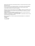
FIGURE 3-7:
Program Counter
As a program instruction is executed, the Program
Counter (PC) will contain the address of the next
program instruction to be executed. The PC value is
increased by one, every instruction cycle, unless an
instruction changes the PC.
LOADING OF PC BRANCH
INSTRUCTIONS – PIC16F57
AND PIC16F59
GOTO Instruction
10
9
8 7
PCL
For a GOTO instruction, bits 8:0 of the PC are provided
by the GOTO instruction word. The PC Latch (PCL) is
mapped to PC<7:0> (Figure 3-6 and Figure 3-7).
Instruction Word
2
For the PIC16F57 and PIC16F59, a page number must
be supplied as well. Bit 5 and bit 6 of the STATUS register provide page information to bit 9 and bit 10 of the
PC (Figure 3-6 and Figure 3-7).
For a CALL instruction, or any instruction where the
PCL is the destination, bits 7:0 of the PC again are
provided by the instruction word. However, PC<8>
does not come from the instruction word, but is always
cleared (Figure 3-6 and Figure 3-7).
0
Status
CALL or Modify PCL Instruction
10
FIGURE 3-6:
LOADING OF PC BRANCH
INSTRUCTIONS – PIC16F54
GOTO Instruction
8
7
0
PCL
PC
CALL or Modify PCL Instruction
PC
Reset to '0'
7
Instruction Word
0
PCL
Instruction Word
2
Reset to ‘0’
PA<1:0>
7
0
Status
3.5.1
PAGING CONSIDERATIONS
PIC16F57 AND PIC16F59
If the PC is pointing to the last address of a selected
memory page, when it increments, it will cause the program to continue in the next higher page. However, the
page preselect bits in the STATUS register will not be
updated. Therefore, the next GOTO, CALL or MODIFY
PCL instruction will send the program to the page
specified by the page preselect bits (PA0 or PA<1:0>).
For example, a NOP at location 1FFh (page 0)
increments the PC to 200h (page 1). A GOTO xxx at
200h will return the program to address xxh on page 0
(assuming that PA<1:0> are clear).
3.5.2
0
PCL
8 7
To prevent this, the page preselect bits must be
updated under program control.
Instruction Word
8
9
PC
For the PIC16F57 and PIC16F59, a page number
again must be supplied. Bit 5 and bit 6 of the STATUS
register provide page information to bit 9 and bit 10 of
the PC (Figure 3-6 and Figure 3-7).
Because PC<8> is cleared in the CALL
instruction or any modified PCL instruction, all subroutine calls or computed
jumps are limited to the first 256 locations
of any program memory page (512 words
long).
PA<1:0>
7
Instructions where the PCL is the destination or modify
PCL instructions, include MOVWF PCL, ADDWF PCL,
and BSF PCL,5.
Note:
0
PC
EFFECTS OF RESET
The PC is set upon a Reset, which means that the PC
addresses the last location in the last page (i.e., the
Reset vector).
The STATUS register page preselect bits are cleared
upon a Reset, which means that page 0 is preselected.
Therefore, upon a Reset, a GOTO instruction at the
Reset vector location will automatically cause the
program to jump to page 0.
© 2007 Microchip Technology Inc.
DS41213D-page 19