1
ULTIMATE A7
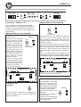
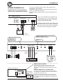
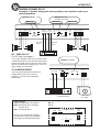
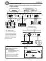
WIRING EXAMPLES A7
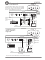
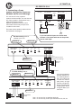
Example 3: System with front speaker system, rear fill speakers and one
or more subwoofers
Highpass filter 125 Hz
Lowpass filter setting 6 kHz
Highpass filter 80 Hz
Button in
FRONT SPEAKERS
+LEFT- +RIGHT-
Button in
HP-filter
LEVEL
IN
240
3,5V
7V 0,2V
Filter
box
SIGNAL INPUTS
FRONT
OUT
x20 change
by bottom switch
+
-
+
-
+
-
OUT
3,5V
0,3 4
kHz
OUT
x10 change
by bottom switch
7V 0,2V
Pre out
rear
FM1
+
-
-
+
Rear fill speakers 125 Hz to 6 kHz
107,3
Lowpass filter 60- 80 Hz
Two-way front system
DC - FEED DLS A7
For DC-feed, see page 4
SIGNAL INPUT
If you have problems with the mid
bass driver ”reaching the bottom”
(the voice coil touches the bottom
pole plate) at high volumes, use
the HP-filter to avoid this with a
setting at 50 - 80 Hz or higher.
Make your own tests.
REAR SPEAKERS
+LEFT- +RIGHT-
LEVEL
IN
2
80 400
Hz
Pre out
front
LP-filter
IN
240
80 400
Hz
Filter
box
+
-
HP-filter
REAR
LEFT RIGHT LEFT RIGHT
Button in
Remote Bass
Level
LEFT SUB RIGHT
FILTER
PHASE
90
IN
O 180
Degree
Low-pass
LEVEL
90
3,5V
50 125
7,0V 0,2V
OUT
FM1
Phase
107,3
Level
Remote Bass Level
& Phase control
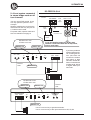
Filter settings:
Front: HP-filter 80 Hz or fullrange
Rear: HP-filter 125 Hz
LP-filter IN. Setting 6 kHz with
x10 switch in position x10
Sub: LP-filter 60-80 Hz
Use one, two or three RCA-cables for
signal from head unit to amplifier.
See page 5 for detailed instructions
SUB-WOOFER
+ SPEAKERS -
Subwoofer
2 - 4 ohm
Switch settings in this example
HP: x1
LP: x10
Input
Front
Rear
x1
Amplifier front
Input to
front, rear
& sub
x 20
Sub input
separate
Input to
rear
& sub
HP
LP
x1
Input
Sub
x 10
Sub input
common
21