1
ULTIMATE A-series
Remote terminal ( REM )
Wiring
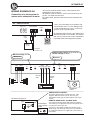
Power, remote and fan terminals
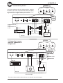
Power terminal for A2, A5, A7
Connect the fuse holder as close to the vehicle battery
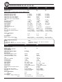
+ as possible, using AWG 5 = 16 mm2 or heavier cable
(see table on page 2). Use ring crimp terminal cable
to connect to battery +. Apply silicon grease to the
fuse to prevent corrosion.
POWER IN
BATT+ REMOTE GND
DLS
For RCA cable signal input:
Connect the radio power antenna lead = remote
turn on/off from the head unit to the amplifier remote
connection. This turns on the amplifier whenever
the car stereo is turned on.
You can either use the built in remote cable in the
RCA cable itself, or use a separate cable.
Sometimes a small disturbance may enter the
amplifier coming from the remote voltage, through
the built in remote wire and into the RCA cable.
Thus we recommend to use a separate remote wire
and run the RCA lead separate from remote wire,
power cables and speaker cables.
You can insert the cable directly into the amplifier
terminal. If there is no remote voltage available from
the stereo, you must connect to the ignition key,
through the radio, or any accessories fuse.
POWER IN
BATT+ REMOTE GND
Battery 12V
DLS FH1B or
FH2B
fuse holder
FM1
Connect the battery cable to the +12 Volt terminal
on the amplifier. Model A2, A5 and A7 accepts AWG
4 = 21 mm2 direct into the terminal. Be sure to use a
rubber grommet or a plastic insulating tube where
the cable passes the firewall or other places where
it can easily be jammed.
Use wire ties to secure to existing cables in the
engine compartment.
107,3
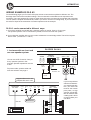
Ground Terminal ( GND )
Connect to a good chassis ground. The ground
connection should be clean, unpainted metal to provide a good electrical connection. Use a wire brush,
a scraper or a piece of an abrasive sheet to clean
the metal. Use a lock washer or two to secure
contact. Protect with silicon grease or by paint
applied afterwards.
POWER IN
BATT+ REMOTE GND
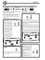
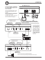
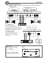
Power terminal for A3, A4 & A6
POWER IN /POWER CAP
POWER IN
GND FAN OUT POS+
BAT+ REM GND
POWER
Fan terminal
PROTECT
Fuse
150 A
To remote
on head unit
+
Battery
12 volt
Fan12 V
Power
capacitor
These models have double DC inputs. The terminals are internally connected so it´s enough to
connect just one of them. If you want to reduce the
voltage drop to the amplifier, use both inputs. The
extra DC input can also be used for the connection
of a Power Capacitor or an extra battery. See the
example above. These amplifiers requires a
powerful fuse holder like the FH2B with an ANL 150
Amp fuse (when using 2AWG / 33 mm2 power
cable).
4
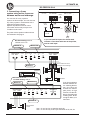
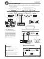
DLS A3, A4, A5, A6 and A7 has a fan
output terminal. On A3, A4 and A6
the terminal is combined with the
extra DC-terminal. The output is
electronically controlled and starts if
the amplifiers is overheated. The terminal is marked "FAN”.
Use a 12 volt DC fan.The speed of
the fan increases when the temperature rises. Direct the fan towards the
amplifier cooling ribs. Full speed is
obtained at 70 degrees C. NOTE!
Maximum load on the FAN terminal
is 0,5 Amp.
Fuses
Use only ATC blade type
fuses. Make sure to replace
with the same value. The
value is printed above the
fuse holders. DLS A4 has no
internal fuses, use an
external fuse instead.
FAN
-
+
Fan 12 V