1
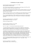
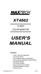
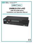
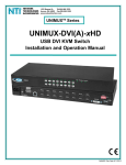
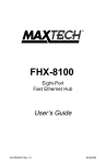
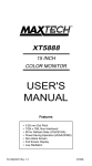
High Performance
Software Configurable
16-bit ISA
NE-2000 compatible
Ethernet Adapters
NX-16 Series
User's Guide
Part #MAN005 Rev. 1.1
REPAIR INFORMATION FORM
Please take a moment to note the following information. Include this form in the unlikly event that
you need to return the product for warranty service.
Refer to Section Eight for complete Warranty
information and procedures on returning your
product.
Product: _________________________
Serial Number: ____________________
Purchase Date: ____________________
Purchased From: __________________
Your Name: ______________________
Address: _________________________
City, State, Zip: ___________________
Day-time Phone #: _________________
Company Name: ___________________
Complete the following information ONLY
after you have been assisted by a Technical
Support Representative:
RMA Number: ____________________
Problem Description: _______________
_________________________________
_________________________________
_________________________________
_________________________________
_________________________________
___________________________________
_______________________________________
_________________________________________
Contents
Section One Section Two Section Three Section Four Section Five Section Six Section Seven Section Eight -
Introduction ......................... 1
Installation ........................... 2
Driver Installation .............. 7
Troubleshooting .................. 7
Cable Information .............. 9
Specifications ..................... 10
Technical Support ............. 11
Warranty, FCC And Other
Information ........................ 12
Section One - Introduction
Maxtech’s NX-16 Series network adapters are high performance, software configurable
Ethernet network adapters. Software configuration provides many advantages over conventional
hardware configured products, including ease of
installation, auto-configuration, and convenient
re-configuration. There is no need to set numerous
and unfamiliar jumpers when installing or reconfiguring the network card. The included setup
program can either automatically select valid I/O
and IRQ addresses when a conflict is detected, or
custom-configure the adapter using parameters of
your choice.
The NX-16 Series network adapter cards
are Industry Standard Architecture (ISA) compatible products and can be used in any IBM PC/XT/AT
or other fully compatible computer. The adapters are
NE-2000 compatible and include a 16KB RAM
buffer for faster network transmission and reception.
1
Minimum hardware requirements are an
IBM PC/XT (or better) fully compatible PC with
512K RAM running DOS 3.3 or higher. The
network operating system you use may have higher
requirements.
Section Two - Installation
This section will provide step by step instructions on how to install your new Maxtech
network adapter. Installation of this network adapter
is a two-step process consisting of actual hardware
installation and card configuration. This network
adapter is designed to be configured using the software included on the installation diskette, eliminating any time-consuming jumper/switch settings.
2.1 Unpacking Your Network Adapter
Three types of network adapter cards are
available. Before you proceed, determine the model
you have purchased. The following table summarizes the contents and features for your Maxtech
Ethernet product:
Model
Adapter Card
RJ-45
BNC
LED (LINK)
BNC T-connector
Boot ROM Socket
Installation disk
User's Guide
NX16T
NX16B
NX16BT
x
x
x
x
x
x
x
x
x
x
x
x
x
x
x
x
2
x
x
x
x
2.2 Hardware Installation
Installation of this adapter card requires
opening and manipulating your PC. Exercise caution at all times when working with AC powered
and static-sensitive equipment. Turn off and unplug your PC before installation. Discharge any
static electricity from your body by touching any
metal surface.
1.
2.
3.
4.
Turn off your computer and all peripherals.
Make a note of the power cord and other
cables connected to your computer and disconnect them.
Remove your computer’s cover (refer to
your computer’s owner manual).
Select any available expansion slot, and
then remove the slot cover (refer to Figure
1). A 16-bit expansion slot is recommended.
Figure 1
5.
Touch the computer chassis before removing the adapter from its anti-static bag. This
will discharge any static electricity from
your body.
3
6.
7.
8.
9.
Carefully install the adapter by firmly pressing the card into the slot you have chosen,
applying even pressure until the adapter is
completely seated in the slot.
Fasten the retaining bracket with the screw
from the slot cover. Make sure the adapter
is properly aligned. Store the slot cover for
future use.
Replace the computer cover and reconnect
the power cord and all cables.
Attach the network cable to your adapter.
2.3 Card Configuration
The following configuration options are
available in the SETUP program:
• Auto Configuration
• Set Configuration
The Auto Configuration option allows
automatic configuration when a Maxtech NX-16
Series network adapter is installed in the PC. This
option will select valid I/O and IRQ addresses
when a conflict is detected with other adapter cards
installed in your PC.
The Set Configuration option allows
selection of operating parameters such as I/O Base
Address, IRQ selection, Transceiver, and Boot
ROM Address.
The default configuration parameters are:
I/O Base Address:
IRQ Line:
Transceiver:
0300H
3
Twisted Pair (BNC on
NX-16B)
Boot ROM Address: Disable
4
Running the SETUP program
1. Insert the installation diskette into your
drive, log on to that drive, and run the
SETUP program in the \DIAG subdirectory.
Assuming that your have inserted the diskette in drive A, you would type the following at the DOS C: drive prompt:
A: [ENTER]
\DIAG\SETUP [ENTER]
2.
3.
Select the network adapter that you would
like to configure (if you have more than one
adapter installed). Otherwise press the Enter key if you have only one adapter installed.
A) Select the Auto Configuration option if
you would like the program to configure
your network card for you (if you have two
or more NX-16 Series adapters installed in
your PC, you will need to install and configure the adapters one at a time).
or
B) Select the Set Configuration option if
you would like to customize the I/O address,
IRQ line, or other operating parameters.
Use the UP or DOWN arrow keys to select
a value from a list of valid values displayed
in a selection window. Press F3 to save the
new setting.
If the Auto Configuration option does not
properly configure your adapter then use
the Set Configuration option to set-up
your adapter.
Do not select IRQ 10, 11, 12, or 15 when
used in an 8-bit slot. 8-bit slots DO NOT
support these IRQs.
5
2.4 Testing The Adapter
The SETUP program provides an option
in its main menu for adapter diagnostics. One or
more PCs on the network can run the test simultaneously. The Test Adapter option runs several
tests and the results are indicated by either PASS
or FAIL. Make sure that the network cable is
attached (and properly terminated if using a BNC
connection) to the adapter when using this option.
If any test fails, the program notifies you of the
error and suggests actions to correct the problem.
Follow the on-screen prompt to start or stop the
Network Function Test.
The following suite of tests are available
through the Test Adapter option:
1.
2.
3.
4.
5.
6.
7.
8.
Configuration Test: Identifies the host PC
I/O Test: Tests configured I/O port
ID Test: Verifies the adapter’s node ID
RAM Test: Checks on-board RAM
Internal Loop back Test: Performs transmit/receive tests within the controller
External Loop back Test: Performs transmit/receive tests on the network link
Interrupt Test: Checks Interrupt Line
Network Function: Performs network
packet transmit/receive tests
2.5 Boot ROM Installation (optional)
An empty ROM socket is provided on the
adapter to accept an optional Remote Boot ROM
(available from your dealer). The Boot ROM allows the PC to load the Operating System over the
network for diskless applications.
1.
Insert the Boot ROM into the socket. Make
6
sure that the notch on the ROM matches
that on the socket (refer to Figure 2).
Figure 2
Align ROM
and socket
notches
2.
3.
Configure the adapter using the SETUP
program to enable the Boot ROM function
by selecting the appropriate address from
the Boot ROM Base Address option. Refer
to Section 2.3 for more information on
running the SETUP program.
Follow the Remote Boot Workstation installation procedure given in your network
operating system manual (i.e. create a Boot
Image on the server for Novell networks, or
start remote booting services on LAN Manager networks, etc.).
Section Three - Driver Installation
The network operating system (i.e. Novell,
LAN Manager, etc.) that you are using requires a
driver to access the network adapter card. The
Maxtech NX-16 Series adapters are NE-2000
compatible and use the NE-2000 driver supplied
with your network operating system. Drivers for
most popular network operating systems are also
included on the installation diskette in separate
subdirectories. Each directory also includes a
7
README.TXT file describing the driver. Refer to
the RELEASE.TXT file on the installation diskette
for more information on the available drivers.
Section Four - Troubleshooting
This section describes some of the common problems you may encounter while using
your network adapter. When troubleshooting, you
should make sure that the network you are connected to is functioning. If you suspect that the
adapter is malfunctioning, replace it with another
adapter which is known to function properly. Also
try the adapter in another computer. This can
indicate whether the adapter or computer causes
the problem. If you can not resolve your difficulty
after reading the following information, contact
your dealer or vendor for assistance.
Most adapter failure after installation is
caused by A) I/O base address and IRQ Line
conflict, or B) Cable problems.
4.1 I/O Base Address and IRQ Conflict
Make sure that the I/O address and IRQ
used by the adapter is not already in use by
another device in your PC. If your PC has builtin serial ports then you will not be able to use IRQ
4 (COM1) or IRQ 3 (COM2). Other adapters in
your system may already use addresses 0300H or
0320H (example: sound/audio card). Vary the
settings on your network adapter by running
SETUP again to eliminate the conflict. Running
the diagnostic in SETUP will also help to detect
configuration conflicts.
8
4.2 Cable Problems
A) Observe the green Link Status LED if
you are using a 10Base-T network. Turn on the
computer. Connect the network cable and observe
the green LINK LED. If the LED is ON, then the
system is connected. Otherwise check for a proper
RJ-45 connection.
B) Make sure the coaxial cable is properly terminated if you are using a 10Base-2
network. Each end of a coaxial segment must be
properly terminated with a 50-ohm terminator.
You may use a simple ohm meter to determine if
the cable is functioning properly. Disconnect all
nodes on the network and measure the resistance
of the terminators. If the terminators do not measure 50 ohms +/- 1%, replace the terminator.
Measure the coaxial cable with a 50-ohm terminator attached to one end. The total resistance of the
cable plus the terminator should be no more than
a few ohms more than the terminator alone.
Section Five - Cable Information
The Maxtech NX-16 Series network
adapters support both popular cable schemes used
in Ethernet networks:
NX-16T - Supports 10Base-T networks.
NX-16B - Supports 10Base-2 networks.
NX-16BT - Supports both 10Base-T and 10Base2 networks.
10Base-T networks use unshielded
twisted-pair cable and 8-pin RJ-45 modular connectors. Use only 22-26 AWG 2-pair 100 ohm/ft
UTP with two to three twists per foot. The cable
9
must use solid copper conductors and UL codes
CM, CMR, and CMP are required. The computer
on the network is connected via a star topology (i.e.
each node is connected to a HUB, not to each
other). Maximum cable length is 300' (100 m).
10Base-2 networks uses a single conductor coaxial cable and BNC connectors. Use only
RG-58A/U or RG-58C/U coaxial cables. Each
network node is connected to the coaxial cable via
a T-connector (included). The minimum distance
between T-connectors is 1.6' (0.5m). The T-connector must be plugged directly into the network
adapter (no cable is allowed between the T-connector and the adapter). No more then 30 connections are allowed per segment and the maximum
segment length is 607' (185 m). The cable must be
terminated at each end by one 50-ohm terminator.
Section Six - Specifications
Network Standard:
IEEE 802.3
EthernetInterface:
ISA bus 8 or 16 bit, auto detect
Hardware Compability: NE2000
I/O address:
200, 220, 240, 260, 300, 320, 340, 360
IRQ line:
2 (9), 3, 4, 5, 10, 11, 12, 15
RAM buffer:
16 KB
Boot ROM address:
C800, CC00, D000, D400, D800, DC00
Power:
0.33A @ 5V
Temperature:
0 to 55 degrees C (Operating); -20 to 80
degrees C (Non-operating)
Humidity:
10% to 90% (Non condensing)
Dimensions:
6.20" x 2.48"
Certification:
FCC Part 15 Class A
Drivers:
Novell NetWare 3.x, 4.0, NetWare LAN WorkPlace
TCP/IP, Novell LAN Analyzer for NetWare, Wollongong Pathway Access, FTP PC/TCP, NCSA TCP/IP, LAN Manager V2.1,
Windows For Workgroups, IBM LAN Server 2.x, IBM LAN
Support V1.2, IBM OS/2 EE V2.0, DEC Pathworks V4.x, SUN
PC-NFS, Banyan VINES V5.5, IBM TCP/IP for DOS and OS/2
10
Section Seven - Technical Support
In the unlikely event you experience difficulty in the use of the
product, or if it does not operate as described, we suggest you: (1)
consult the Troubleshooting section of this guide and (2) consult
with your dealer.
If you have not referred to the Troubleshooting section, there
is a good chance the solution to your problem is there. If you
still can not solve the problem, call the Maxtech Service Center at
(201) 579-2954 between 9:00 a.m. and 5:30 p.m. (EST Monday
through Friday). If the nature of your question is related to the
network operating system that you are using, refer to its
manual. Calling the Service Center without complete and accurate
information concerning the NATURE OF THE PROBLEM
will be both time-consuming and frustrating for you.
You may also reach us through our electronic BBS. Any revisions
or updates of available drivers will be posted on the BBS. This
service is available 24 hours a day at: (201) 579-2380
Section Eight - Warranty, FCC, And
Other Information
7.1 Five Year Limited Warranty
Maxtech warrants to the original buyer of this product against
defects in material and workmanship for five years from the date
of purchase. During the warranty period, Maxtech will repair (or
at its option, replace) the product that proves to be defective,
provided the product has not been abused, misused, modified, or
repaired by an unauthorized center.
In the event the product requires service, follow the procedure
outlined in Section Seven - Technical Support. When you are
instructed by the Technical Support Representative to return the
product to Maxtech for repair, you will be given an RMA (Return
Merchandise Authorization) number.You must have an RMA
Number to return the product for service. Use the following
procedure to return the product to Maxtech:
1.
2.
Return the product in its original package and packing (if
possible), and put it in a sturdy corrugated box.
Be sure to complete the Repair Information Form, including your name, address, day-time telephone number,
RMA number, and a brief description of the problem
11
4.
5.
(also enclose a check for out-of-warranty repair). Enclose your check or Postal Money Order for $7.50 to
cover the cost of return shipping/handling. Please do not
send cash or stamps.
After wrapping the package securely for shipping, print
your name, return address and the RMA # clearly on the
outside of your package.
Ship the unit prepaid via UPS or the U.S. Postal Service
To the address provided by the technician when you call.
We recommend that the unit be insured.
This warranty is valid for products sold in North America only.
Contact your local authorized distributor or dealer for the warranty offered in other areas.
All warranty services must be performed by Authorized Service
Centers. There are no user servicable parts inside the unit. Do not
remove any components or attempt to service the unit by any
unauthorized service center. This warranty is voided if the product
has been abused, misused, modified, or repaired by an unauthorized service center.
7.2 FCC Compliance
This device complies with Part 15 of the FCC Rules. Operation is
subject to the following two conditions: (1) this device may not
cause harmful interference, and (2) this device must accept any
interference received, including interference that may cause
undersirable operation.
7.3 Disclaimer, Copyright, And Other Notices
The information contained in this manual has been validated at the
time of this manual's production. The manufacturer reserves the
right to make any changes and improvements in the product
described in this manual at any time and without notice. Consequently the manufacturer assumes no liability for damages incurred directly or indirectly from errors, omissions or discrepancies between the product and the manual.
All registered trademarks are the property of their respective
owners.
Copyright © 1994 Maxtech. All rights reserved. No reproduction
of this document in any form is allowed without written permission from Maxtech.
First Edition
GZ/DR - Version 1.1
12